WO2010137465A1 - プラスチック光ファイバコードユニット - Google Patents
プラスチック光ファイバコードユニット Download PDFInfo
- Publication number
- WO2010137465A1 WO2010137465A1 PCT/JP2010/058105 JP2010058105W WO2010137465A1 WO 2010137465 A1 WO2010137465 A1 WO 2010137465A1 JP 2010058105 W JP2010058105 W JP 2010058105W WO 2010137465 A1 WO2010137465 A1 WO 2010137465A1
- Authority
- WO
- WIPO (PCT)
- Prior art keywords
- optical fiber
- plastic optical
- fiber cord
- cord
- connecting bridge
- Prior art date
- Legal status (The legal status is an assumption and is not a legal conclusion. Google has not performed a legal analysis and makes no representation as to the accuracy of the status listed.)
- Ceased
Links
Images






Classifications
-
- G—PHYSICS
- G02—OPTICS
- G02B—OPTICAL ELEMENTS, SYSTEMS OR APPARATUS
- G02B6/00—Light guides; Structural details of arrangements comprising light guides and other optical elements, e.g. couplings
- G02B6/44—Mechanical structures for providing tensile strength and external protection for fibres, e.g. optical transmission cables
- G02B6/4401—Optical cables
- G02B6/4403—Optical cables with ribbon structure
-
- G—PHYSICS
- G02—OPTICS
- G02B—OPTICAL ELEMENTS, SYSTEMS OR APPARATUS
- G02B6/00—Light guides; Structural details of arrangements comprising light guides and other optical elements, e.g. couplings
- G02B6/24—Coupling light guides
- G02B6/36—Mechanical coupling means
- G02B6/38—Mechanical coupling means having fibre to fibre mating means
- G02B6/3807—Dismountable connectors, i.e. comprising plugs
- G02B6/3873—Connectors using guide surfaces for aligning ferrule ends, e.g. tubes, sleeves, V-grooves, rods, pins, balls
- G02B6/3885—Multicore or multichannel optical connectors, i.e. one single ferrule containing more than one fibre, e.g. ribbon type
-
- G—PHYSICS
- G02—OPTICS
- G02B—OPTICAL ELEMENTS, SYSTEMS OR APPARATUS
- G02B6/00—Light guides; Structural details of arrangements comprising light guides and other optical elements, e.g. couplings
- G02B6/24—Coupling light guides
- G02B6/36—Mechanical coupling means
- G02B6/38—Mechanical coupling means having fibre to fibre mating means
- G02B6/3807—Dismountable connectors, i.e. comprising plugs
- G02B6/3887—Anchoring optical cables to connector housings, e.g. strain relief features
- G02B6/3888—Protection from over-extension or over-compression
-
- G—PHYSICS
- G02—OPTICS
- G02B—OPTICAL ELEMENTS, SYSTEMS OR APPARATUS
- G02B6/00—Light guides; Structural details of arrangements comprising light guides and other optical elements, e.g. couplings
- G02B6/24—Coupling light guides
- G02B6/42—Coupling light guides with opto-electronic elements
- G02B6/4201—Packages, e.g. shape, construction, internal or external details
- G02B6/4249—Packages, e.g. shape, construction, internal or external details comprising arrays of active devices and fibres
Definitions
- the present invention relates to a plastic optical fiber cord unit in which a connector for connection is attached to a plastic optical fiber cord in which a plurality of plastic optical fibers are integrated in a tape shape and used in an optical module, in particular
- the present invention relates to a plastic optical fiber cord unit suitable for image-related optical link systems.
- plastic optical fibers are all made of plastic, so that they have the disadvantage that the transmission loss is somewhat large compared to quartz-based optical fibers, but they are lightweight and have good machinability and low cost. It has the advantage of being manufacturable, and it is widely used as a short-distance optical transmission path in which the transmission loss is not a problem in various optical modules that transmit and receive optical communications.
- Patent Document 1 describes that as a plastic optical fiber cord used in an optical module, one in which four optical fibers are aligned and collectively covered in a tape shape with a synthetic resin tape-forming material is suitable.
- a connector for connection is attached to the plastic optical fiber cord.
- a connector in Patent Document 2, a plastic light in which a coating layer is peeled from a plastic optical fiber in a cord housing portion of the connector It is shown that a wire insertion hole for inserting a fiber wire and a main body insertion portion for inserting a main body portion including a covering layer are provided.
- JP 2008-10837 A (for example, its FIG. 5) JP-A-7-63917
- An object of the present invention is to provide a plastic optical fiber cord unit capable of easily performing wiring work and solving the problem of the plastic optical fiber cord coming off from the connector.
- a plastic optical fiber cord unit is a plastic optical fiber cord unit comprising a plastic optical fiber cord in which a plurality of plastic optical fibers are integrated in a tape shape, and a connector attached to the end of the plastic optical fiber cord.
- the plastic optical fibers are connected to each other via a connecting bridge, and the connector is characterized by having a pressing member for preventing the plastic optical fiber cord from coming off by pressing the connecting bridge. It is.
- a plastic optical fiber (hereinafter sometimes referred to as "POF") is a clad composed of a core composed of an organic compound having a polymer as a matrix and a core and a core different in refractive index (generally a polymer of low refractive index) And a plurality of resin protective layers.
- the POF may be referred to as a step index (SI) type composed of a two-layer structure in which a material having a high refractive index is in the core and a material having a low refractive index is in the cladding, and From the center to the outside (radial direction) may be referred to as a graded index (GI) type having a core having a distribution in the size of the refractive index.
- SI step index
- GI graded index
- the protective layer surrounding the cladding may be three or more layers, in which case the outermost layer corresponds to the second protective layer (the first protective layer may be composed of a plurality of layers), and for connection The bridge is integrally formed on this outermost protective layer.
- the multiple resin protective layers are partially peeled off at the time of connection with the connector, and in this specification, the protective layer to be peeled is referred to as a covering layer, and the plastic optical fiber (POF) extends to the covering layer.
- a plastic optical fiber (POF) which is to be included and whose covering layer is peeled off for attaching a connector is called a plastic optical fiber (POF) wire.
- the conventional plastic optical fiber cord has a structure in which the POF is solidified with resin so as to maintain a horizontal row of flat state, whereas in the plastic optical fiber cord according to the present invention, the POFs have a second protection.
- the layers and the thickness are connected via a connecting bridge of approximately equal thickness. In this way, the flexibility of the connecting bridge not only allows the plastic optical fiber cord to be treated as flat but also when the circular hole is inserted. It can be deformed.
- the articulating bridge has lower strength against tearing as compared with the conventional one, it is possible to easily separate the plastic optical fiber cord into a single POF. Therefore, it is suitable for use in wiring in a television.
- the connector has a module housing in which a cord accommodating portion is formed, and a pressing member for clamping an end of a plastic optical fiber cord inserted into the cord accommodating portion to one side of the cord accommodating portion It is assumed.
- a connector is known, and in the conventional connector, when the plastic optical fiber cord is pressed firmly by the holding member to prevent the plastic optical fiber cord from coming off, the POF wire is damaged or Since the loss due to the side pressure increases, it is difficult to adjust the pressing force, and as a result, there is a problem that the plastic optical fiber cord is easily detached from the connector, or a problem occurs that the POF wire is damaged or the loss increases due to the side pressure.
- the plastic optical fiber cord unit is applied without stressing the POF wire by holding the connecting bridge by one side surface of the cord housing and the pressing member.
- the cord can be strongly pressed, and damage to the POF strand and increase in loss due to lateral pressure can be prevented, and the plastic optical fiber cord can be prevented from coming off.
- the specific configuration of the connector may be various, and the pressing member may be, for example, a slider slidably disposed in the cord housing, and a cover for protecting the module housing Can be integrally formed.
- the pressing member may be subjected to asperities or other processing.
- the connecting bridge may be held between the slider and any of the upper and lower surfaces of the cord housing portion, and elastic deformation between the upper and lower surfaces of the cord housing portion is also possible.
- a possible intermediate wall is integrally formed on the module housing, and the connecting bridge is sandwiched between the intermediate wall and the upper surface (or lower surface) of the cord housing, and the sliding of the slider elastically deforms the intermediate wall,
- An intermediate wall may be interposed between the connecting bridge and the connecting bridge, and the connecting bridge may be held between the slider and any of the upper and lower surfaces of the cord housing.
- the friction between the slider and the intermediate wall is smaller than the friction between the slider and the connecting bridge, which makes it easy to slide the slider and also pulls the plastic optical fiber cord. The slider is reliably prevented from coming off.
- asperities are formed at predetermined intervals in a direction parallel to the axial direction of the plastic optical fiber on at least one surface of the connecting bridge of the plastic optical fiber cord. That is, both sides (upper and lower sides) of the conventional plastic optical fiber cord are flat and inserted into the connector, and when a tensile force acts in the direction opposite to the insertion direction, the plastic optical fiber cord In the plastic optical fiber cord according to the present invention, the connecting bridge is pressed by the pressing member, and at least one surface of the connecting bridge is uneven. .
- the thickness of the connecting bridge (in the case where unevenness is formed on only one side, the distance from the flat surface of the connecting bridge to the tip of the projection is referred to, and in the case where unevenness is formed on both sides)
- the distance from the tip of one convex part of the bridge to the tip of the other convex part is made larger than the gap formed between the pressing member and the bridge accommodating part, and plastic light
- the convex part of the connecting bridge is elastically deformed, thereby increasing the resistance when a tensile force is applied to the plastic optical fiber cord in the direction opposite to the insertion direction. ,
- the plastic fiber optic cord pull-out prevention performance is further improved.
- the pressing member of the connector When the connection bridge is provided with the unevenness, the pressing member of the connector may or may not be provided with the unevenness. And, when the pressing member of the connector is provided with irregularities, the irregularities of the pressing member may be made to correspond to the irregularities of the connecting bridge so that these may be fitted to each other. You may make it contact
- the second protective layer and the connecting bridge are formed by extrusion on the plastic optical fiber strand comprising the core, the clad surrounding the core, and the first protective layer surrounding the clad. It is preferable that the concavities and convexities of the connecting bridge are formed by pressing a forming roll having concavities and convexities corresponding to the concavities and convexities immediately after extrusion on the connecting bridge in a plastic state. By doing this, it is possible to obtain the plastic optical fiber cord according to the present invention through the same steps as in the prior art except for adding a forming roll.
- one pair of forming rolls may be used, and the connecting bridge may be sandwiched by the forming rolls from both sides.
- the number of the forming rolls may be one, and the connecting bridge may be sandwiched between the forming roll and the holding roll or the holding plate on which the unevenness is not formed.
- the core diameter of POF is, for example, 100 ⁇ m or more and 300 ⁇ m or less. Moreover, the diameter of the POF strand is 2 mm or less.
- the types of plastic used as the core and the cladding are not limited as long as they are highly transparent and can be used for light transmission.
- polymers of (meth) acrylic acid ester monomers and polymers of styrenic monomers can be mentioned.
- a (meth) acrylic acid ester type monomer methyl methacrylate (MMA), ethyl methacrylate, n-propyl methacrylate, n-butyl methacrylate, methyl acrylate, ethyl acrylate, n-propyl acrylate, n-acrylate
- examples of the styrene-based monomer include styrene (St), ⁇ -methylstyrene, chlorostyrene (ClSt), and bromostyrene.
- Copolymers of these may also be used.
- Other copolymerization components include vinyl esters such as vinyl acetate, vinyl benzoate, vinyl phenyl acetate, vinyl chloroacetate, etc .; N-n-butyl maleimide, N-tert-butyl maleimide, N-isopropyl maleimide, N-cyclohexyl maleimide, etc. Maleimides etc. are illustrated.
- polycarbonate plastic, cycloolefin plastic, amorphous fluorine plastic and the like can also be used.
- the synthetic resin forming the protective layer of the POF and the connecting bridge is not particularly limited, but ones satisfying the strength, flame retardancy, flexibility, chemical resistance, heat resistance, etc. necessary for the use of the plastic optical fiber cord It is preferable to select For example, vinyl chloride resin, chlorinated vinyl chloride resin, low density polyethylene, high density polyethylene, chlorinated polyethylene, ethylene-vinyl acetate copolymer, polyvinyl chloride-ethylene-vinyl copolymer, etc., acrylic resin, fluorine Examples thereof include those based on a resin, vinyl acetate-vinyl chloride copolymer, polycarbonate and the like.
- the connecting bridge may be provided on the bottom (bottom) or top (top) of the cables when the cables are arranged in a horizontal row on the horizontal surface, and the upper and lower centers It may be provided at the same level as the central axis) and may be provided at any position between the bottom or top surface and the upper and lower just centers.
- Each connecting bridge is usually provided at the same position (so that all connecting bridges are in the same plane), but is not limited thereto.
- the connecting bridge When the connecting bridge is provided on the bottom surface (lowest point) or the top surface (upper point) in the case where a plurality of cables are arranged in a horizontal row on the horizontal surface, the plurality of cables are deformed into a rounded state
- a plurality of cables may be deformed so as to come to the outside of the connection bridge, or a plurality of cables may be made to come inside the connection bridge. It may be transformed into a state.
- the plastic optical fiber cord can be used for various applications, it is suitable for video signal transmission in an optical transmission device (optical link system) that transmits an optical signal through an optical fiber, and the wiring space is restricted.
- the wavelength of the POF is preferably 500 to 850 nm, and may be 500 to 750 nm (visible light) or even a light source (infrared) of 780 to 850 nm. Good.
- the plastic optical fiber cord unit of the present invention since the plastic optical fibers are connected to each other via the connecting bridge, the wiring work in the video related optical link system such as the wiring in the television can be easily performed.
- the connector since the connector has a pressing member that prevents disconnection of the plastic optical fiber cord by pressing the connecting bridge, the plastic optical fiber cord can be strongly pressed without stressing the plastic optical fiber strand. It is possible to prevent the plastic optical fiber from being scratched and to solve the problem of detachment after the plastic optical fiber cord is attached to the connector.
- the load on the plastic optical fiber is reduced, it is possible to prevent an increase in loss due to side pressure.
- FIG. 1 is a view showing a first embodiment of a plastic optical fiber cord unit according to the present invention, and shows a state before the plastic optical fiber cord (shown in plan view) is inserted into the connector (shown in sectional view) .
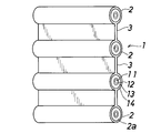
- FIG. 2 is a perspective view showing the plastic optical fiber cord of the first embodiment.
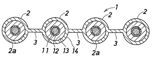
- FIG. 3 is a cross-sectional view of the same.
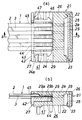
- FIG. 4 is a view showing a first embodiment of the plastic optical fiber cord unit according to the present invention, showing a state after the plastic optical fiber cord is inserted into the connector, wherein (a) is a plan sectional view (FIG. 1 (b) is a cross-sectional view taken along the line bb of (a).
- FIG. 5 is a view showing a first embodiment of a plastic optical fiber cord unit according to the present invention, showing a procedure for connecting the plastic optical fiber cord to the connector, wherein (a) shows the state before inserting the plastic optical fiber cord
- FIG. 6B is a cross-sectional view showing the state before sliding of the slider after insertion of the plastic optical fiber cord
- FIG. 7C is a cross-sectional view showing the state after sliding of the slider
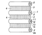
- FIG. 6 is a perspective view showing a plastic optical fiber cord in a second embodiment of the plastic optical fiber cord unit according to the present invention.
- FIG. 7 is a cross-sectional view of the same.
- FIG. 8 is a longitudinal cross-sectional view of the connecting bridge of the plastic optical fiber cord of the second embodiment.
- FIG. 9 is a side view showing an example of a manufacturing process for obtaining the plastic optical fiber cord of the second embodiment.
- FIG. 10 is an enlarged sectional view of an essential part showing a state after sliding of the slider in the plastic optical fiber cord unit of the second embodiment.
- FIG. 11 is an enlarged sectional view of an essential part showing a state after sliding of the slider in the third embodiment of the plastic optical fiber cord unit according to the present invention.
- FIG. 12 is a view showing a fourth embodiment of the plastic optical fiber cord unit according to the present invention, showing a procedure for connecting the plastic optical fiber cord to the connector, wherein (a) shows the state before inserting the plastic optical fiber cord
- FIG. 6B is a cross-sectional view showing the state before sliding of the slider after insertion of the plastic optical fiber cord, and FIG.
- FIG. 7C is a cross-sectional view showing the state after sliding of the slider .
- FIG. 13 is a cross-sectional view showing a fifth embodiment of the plastic optical fiber cord unit according to the present invention, and shows a state after insertion of the plastic optical fiber cord.
- FIG. 1 to 5 show a first embodiment of a plastic optical fiber cord unit according to the present invention.
- the plastic optical fiber cord unit comprises a plastic optical fiber cord (1) in which a plurality of plastic optical fibers (2) are integrated in a tape shape, and a connector (21) attached to the end of the plastic optical fiber cord (1) It consists of
- the plastic optical fiber cord (1) comprises a POF (plastic optical fiber) (2) and a connecting bridge (3) for connecting the POFs (2).
- the plurality of POFs (2) are arranged in a row in a horizontal row at a predetermined interval between adjacent ones, and the connecting bridges (3) are arranged in this manner for each of the POFs (2) It is provided so as to connect the upper and lower centers of.
- this plastic optical fiber cord (1) When this plastic optical fiber cord (1) is installed along a horizontal plane, a vertical plane or the like, a plurality of POFs (2) are arranged in a horizontal row, and can be used in a flat state.
- the plastic optical fiber cord (1) can be easily deformed into a state in which the plurality of POFs (2) are in a full state, and in this way, the plastic optical fiber cord (1) can be passed through the hole. Can be done easily.
- each POF (2) has a core (11) made of an organic compound having a polymer as a matrix, and the core and the refractive index are different (generally, a low refractive index polymer) And an overcladding (first protective layer) (13) and a jacket (second protective layer) (14) for protecting them.
- the connecting bridge (3) is integrally formed with the jacket (14).
- a core (11), a clad (12) surrounding the core (11), and a strand (2a) consisting of an overcladding (13) surrounding the clad (12) are arranged in parallel
- These strands (2a) are coated with a jacket (14) by extrusion molding, and formed by connecting the jackets (14) with a connecting bridge (3).
- the connection end of the plastic optical fiber cord (1) is stripped of its jacket (14) and the connecting bridge (3) and consists only of a plurality of POF strands (2a) It is assumed.
- the plastic optical fiber cord (1) has a four-core tape structure composed of four POFs (2) so as to obtain a high transmission rate.
- the conventional four-fiber cord is structured with resin so as to hold four horizontal rows of flat state, according to this plastic optical fiber cord (1) It becomes possible to deform from a flat state and a two-row double-layered state in which two inner POFs (2) are lined up and two inner POFs (2) are lined up from this state. ing.
- the plastic optical fiber cord (1) of the four-core tape structure may be two-core or single-core at the end or appropriate middle part, and by tearing each connecting bridge (3), The 4-core tape structure can be easily separated into single cores.
- the connector (21) includes a module housing (22) in which a substrate housing portion (23) and a cord housing portion (24) are formed, an optical transmission / reception substrate (25) disposed in the substrate housing portion (23), and a module housing (22) A shield cover (26) for protecting the slider, and a slider (pressing member) (27) slidably disposed in the cord housing (24).
- the module housing (22) and the slider (27) are resin molded products, and the shield cover (26) is a pressed product of a thin metal plate.
- the cord accommodating portion (24) is for accommodating the end of the plastic optical fiber cord (1) such that the POF wire (2a) is positioned relative to the light transmitting / receiving board (25), and the connector (21)
- a plurality of POF strands (2a) are formed in parallel so as to be respectively inserted in parallel to each other at the connection end of the plastic optical fiber cord (1).
- a (cylindrical) strand insertion hole (28) and a body insertion portion (29) for inserting an end of a body portion (non-peeling portion) of the plastic optical fiber cord (1) are provided.
- the main body portion of the plastic optical fiber cord (1) is formed by connecting the POFs (2) to each other by the connecting bridge (3) as described above, the main body insertion portion (29)
- a POF accommodating portion (29a) for accommodating each POF (2) and a bridge accommodating portion (29b) for accommodating the connecting bridge (3) are provided.
- the slider (27) is positioned on the opening side of the cord housing (24) (FIG. 5 (a)) ), Insert the end of the plastic optical fiber cord (1) into the cord housing (24) from the opening side (FIG. 5 (b)), and then the slider (27) on the back side of the cord housing (24) (Fig. 5 (c)).
- the slider (27) has a rectangular plate-like horizontal portion (41) for supporting the plastic optical fiber cord (1) from the lower side in the cord housing portion (24), and a horizontal portion (41) outside the cord housing portion (24). And a rectangular plate-like vertical portion (42) integrated with the
- a semi-cylindrical shape receiving the POF (2) corresponding to the plastic optical fiber cord (1) in which the POF (2) and the connecting bridge (3) are alternately arranged in the width direction The concave surface (43) of the present invention and the uneven surface (44) for receiving the connecting bridge (3) are provided alternately with the uneven surface being formed in the sliding direction of the slider (27).
- the vertical portion (42) has a stopper function to abut the opening edge (24a) of the cord housing (24) when the slider (27) is slid to the back side, and the slider (27) Also has a function to make it easy to hold by hand when sliding the A through hole or a notch (45) for inserting the plastic optical fiber cord (1) is formed in the upper part of the vertical portion (42), and the plastic optical fiber cord (1) It is inserted into the cord housing (24) through the notch (45).
- the horizontal portion (41) engages with the opening edge (24a) of the cord housing (24) when sliding the slider (27) toward the opening side, and the slider (27)
- a drop-off preventing claw (46) is provided to prevent the dropout from 24).
- a convex portion (47) having an inclined surface on the back side and the opening side is formed. The convex portion (47) suppresses the further movement of the slider (27) by engaging with the opening edge portion (24a) of the cord accommodating portion (24), but prevents the further movement.
- the sloped surface on the back side can climb over the opening edge (24) of the cord housing (24), and to the opening side of the slider (27) At the time of movement, the inclined surface on the opening side can climb over the opening edge (24a) of the cord housing (24).
- An inclined step is provided at an intermediate portion of the upper surface of the cord storage portion (24), and the upper surface of the bridge storage portion (29b) is made lower than the upper surface on the opening side.
- An inclined step is provided in the middle portion of the lower surface, and the lower surface of the bridge housing portion (29b) is made higher than the lower surface on the opening side.
- the distance between the upper surface and the lower surface of the bridge accommodating portion (29b) of the cord accommodating portion (24) is obtained by adding the thickness of the horizontal portion (41) of the slider (27) and the thickness of the connecting bridge (3) It is slightly smaller (the thickness of the connecting bridge (3) is larger than the gap formed between the slider (27) and the bridge housing (29b)). Therefore, in the state of FIG.
- the distance between the upper surface and the lower surface of the POF storage portion (29a) of the cord storage portion (24) is slightly larger than the sum of the thickness of the horizontal portion (41) of the slider (27) and the thickness of the POF (2) It is supposed to be. Therefore, when the slider (27) is slid to the back side, the POF (2) and the POF strand (2a) are positioned by the strand insertion hole (28) and the POF storage part (29a). The POF wire (2a) is prevented from being damaged, and an increase in loss due to lateral pressure is also prevented.
- FIG. 6 to 10 show a second embodiment of the plastic optical fiber cord unit according to the present invention.
- the same components as those of the first embodiment are denoted by the same reference numerals, and the description thereof is omitted.
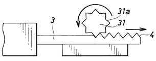
- the unevenness (4) of the connecting bridge (3) is, as shown in FIG. 9, immediately after extrusion molding, the forming roll (31) having the unevenness (31a) corresponding to the unevenness (4) on the outer peripheral surface is in a plastic state
- the connecting bridge (3) is formed by being pressed against the upper surface of the connecting bridge (3).
- the thickness (the distance from the lower surface of the connecting bridge (3) to the tip of the projection (4a)) of the connecting bridge (3) having the unevenness (4) formed on the upper surface is the slider (27)
- the main body of the plastic optical fiber cord (1) is inserted into the main body insertion part (29) of the connector (21)
- the convex portion (4a) of the connecting bridge (3) is elastically deformed and accommodated in the bridge accommodating portion (29b).
- FIG. 10 the concavo-convex surface (44) of the slider (27) is in contact with the lower surface (surface without concavities (4)) of the connecting bridge (3), but FIG. 11 (third embodiment) The same effect can be obtained even if the concavo-convex surface (44) of the slider (27) and the concavo-convex (4) of the connecting bridge (3) just fit each other as shown in FIG.
- the unevenness (4) of the connecting bridge (3) is formed only on one side of the connecting bridge (3), it is provided on both sides of the connecting bridge (3) You may As shown in FIG. 9, the forming roller 31 disposed above the connecting bridge 3 is disposed below the connecting bridge 3 as shown in FIG. 9, and the pair of forming rolls 31 It can be formed by sandwiching the connecting bridge (3) in the state from both upper and lower sides.
- FIG. 12 shows a fourth embodiment of the plastic optical fiber cord unit according to the present invention.
- the same components as those of the first embodiment are denoted by the same reference numerals, and the description thereof is omitted.
- the connector (21) is attached to the plastic optical fiber cord (1) in the same manner as in the first embodiment, and as shown in FIG. 12, the slider (37) Of the end of the plastic optical fiber cord (1) is inserted into the cord housing (24) from the opening side (FIG. 12). (B) Then, the slider (37) is slid to the back side of the cord housing (24) (FIG. 12 (c)).
- the cord housing portion (24) is provided with an intermediate wall (38) which divides the cord housing portion (24) up and down, and the slider (37) comprises the intermediate wall (38) and the cord housing portion It is made to be inserted between the lower surface of (24).
- the intermediate wall (38) is integrally formed on the module housing (22) and made of resin, so it can be elastically deformed.
- the upper surface of the slider (37) is provided with a step (48a) at the middle portion, and the opening side is made higher than the back side, and when the slider (37) is inserted in the back side, the middle wall (38) It is lifted upward by the upper surface on the open side of (37).
- a portion of the cord housing (24) above the middle wall (38) is provided on the upper surface of the cord housing (24) and has a projection (24b) projecting downward and the top of the middle wall (38)
- the bridge housing portion (29b) for housing the connecting bridge (3) is formed by the convex portion (38a) provided on the upper side and the bridge housing portion (29b) on both sides (in FIG.
- a POF storage portion (29a) is formed by the upper surface of the cord storage portion (24) where the convex portion (24b) (38a) is not provided and the upper surface of the intermediate wall (38).
- the slider (37) has a rectangular plate-like horizontal portion (48) and a rectangular plate-like vertical portion (49) integrated with the horizontal portion (41) outside the cord housing (24) There is.
- the planar shape of the horizontal portion (48) is the same as that of the slider (27) of the first embodiment shown in FIG. 1 and the like, but the horizontal portion (48) is in the cord storage portion (24). Since the plastic optical fiber cord (1) is not supported from the lower side, the plastic light is only formed on the upper surface with a step (48a) for lifting the above-mentioned intermediate wall (38) upward. No concave or convex surface corresponding to the fiber cord (1) is formed.
- a notch or through hole (50) for inserting the plastic optical fiber cord (1) is formed in the upper part of the vertical portion (49), and the plastic optical fiber cord (1) It is inserted into the cord housing (24) through the hole (50).
- the distance between the upper surface and the lower surface of the bridge housing (29b) is slightly larger than the thickness of the connecting bridge (3). Therefore, in the state shown in FIG. 12 (a), the POF (2) of the plastic optical fiber cord (1), the connecting bridge (3) and the POF wire (2a) are inserted without resistance into the main body insertion portion (29) and the wire insertion. It can be inserted into the hole (28). And in the state of FIG.12 (b), although there is a slight clearance between the connection bridge (3) and the bridge accommodating part (29b), by sliding the slider (37) to the back side, As shown in FIG.
- the opening side portion of the intermediate wall (38) is lifted upward by the upper surface on the opening side of the slider (37), and the connecting bridge (3) Of the plastic optical fiber cord (1) is prevented by the projection (24b) and the projection (38a) on the upper surface of the intermediate wall (38).
- the distance between the upper surface and the lower surface of the POF storage portion (29a) of the main body insertion portion (29) is slightly larger than the diameter of the POF (2), and the slider (37) was slid to the back side
- the POF (2) and the POF wire (2a) are positioned by the wire insertion hole (28) and the POF accommodating portion (29a) but not strongly pressed, thereby the POF wire (2a) is prevented from being damaged, and an increase in loss due to lateral pressure is also prevented.
- the plastic optical fiber cord unit of the fourth embodiment is between the slider (37) and the connecting bridge (3) Is different in that an intermediate wall (38) is interposed.
- the frictional force between the slider (37) and the intermediate wall (38) is smaller than the frictional force between the slider (27) of the first embodiment and the connecting bridge (3).
- the movement of the slider (37) is smooth, and it becomes easy to slide the slider (37).
- the fourth embodiment even when the plastic optical fiber cord (1) is pulled, this force does not act on the slider (37), so that the slider (37) does not come off. .
- FIG. 13 shows a fifth embodiment of the plastic optical fiber cord unit according to the present invention.
- the same components as those of the first embodiment are denoted by the same reference numerals, and the description thereof is omitted.
- the pressing member is integrally formed not on the slidable slider (27) but on the shield cover (26) which is a pressed product of a thin metal plate. It is considered as a substantially L-shaped pressing piece (51).
- the distance between the lower surface of the pressing piece (51) and the upper surface of the bridge accommodating portion (29b) is slightly smaller than the thickness of the connecting bridge (3), and the pressing member (51) Is forcibly inserted between the lower surface of the lower case and the upper surface of the bridge accommodating portion (29b), the connecting bridge (3) is formed by the lower surface of the pressing piece (51) and the upper surface of the bridge accommodating portion (29b). It is firmly held, whereby the plastic optical fiber cord (1) is prevented from coming off.
- the connector (21) has a simple structure to prevent damage to the POF wire (2a) and an increase in loss due to side pressure, and a plastic optical fiber cord from the connector (21) It is possible to prevent the omission of 1).
- Each of the above connectors (21) is flat, which enables a thin structure of the connection portion of the plastic optical fiber cord (1).
- the plastic optical fiber cord (1) according to the present invention The connector attached to is not limited to the one described above, and various forms can be used.
- the plastic optical fiber cord (1) can be used in combination with various optical modules, and its application is not limited. However, there is a height restriction and the restriction of the wiring space is strict. Particularly suitable for link systems.
- a wavelength of POF (2) when used for wiring in a television, it is preferable that it is 500-850 nm, 500-750 nm (visible light) may be sufficient, and 780-850 nm light source (infrared ray) ) May be.
- Plastic optical fiber cord (2) POF (plastic optical fiber) (2a) POF (plastic optical fiber) wire (3) Bridge for connection (4) Irregularities (11) Core (12) Clad (13) Over clad (first protective layer) (14) Jacket (second protective layer) (21) Connector (27) Slider (pressing member) (31) Forming roll (31a) unevenness (37) Slider (pressing member) (51) Pressing piece (pressing member)
Landscapes
- Physics & Mathematics (AREA)
- General Physics & Mathematics (AREA)
- Optics & Photonics (AREA)
- Optical Couplings Of Light Guides (AREA)
- Mechanical Coupling Of Light Guides (AREA)
Abstract
配線作業を容易に行うことができるとともに、コネクタからのプラスチック光ファイバコードの抜けの問題を解消したプラスチック光ファイバコードユニットを提供する。 プラスチック光ファイバ2同士は、連接用ブリッジ3を介して接続されている。コネクタ21は、連接用ブリッジ3を押さえることでプラスチック光ファイバコード1の抜けを防止する押さえ部材としてのスライダ27を有している。
Description
本発明は、複数本のプラスチック光ファイバをテープ状に一体化したプラスチック光ファイバコードに接続用のコネクタが取り付けられて光モジュールで使用されるプラスチック光ファイバコードユニットに関し、特に、テレビ内配線等の映像関連光リンクシステムに適したプラスチック光ファイバコードユニットに関する。
光ファイバのうちプラスチック光ファイバは、素材が全てプラスチックで構成されているため、伝送損失が石英系光ファイバと比較してやや大きいという短所を有するものの、軽量で加工性が良く、また、低コストで製造可能であるという長所を有しており、光通信の送受を行う各種の光モジュールにおいて、その伝送損失が問題にされない近距離の光伝送路として多用されている。
特許文献1には、光モジュールで使用されるプラスチック光ファイバコードとして、4本の光ファイバを並べて、合成樹脂製のテープ化材によってテープ状に一括被覆したものが適することが記載されている。
また、プラスチック光ファイバコードには、接続のためのコネクタが取り付けられるが、このようなコネクタとして、特許文献2には、コネクタのコード収容部に、プラスチック光ファイバから被覆層が剥離されたプラスチック光ファイバ素線を挿入する素線挿入孔と、被覆層を含んだ本体部分を挿入する本体挿入部とが設けられているものが示されている。
プラスチック光ファイバコードをテレビ内配線などに使用するに際しては、配線作業を容易に行えることが課題となっており、また、プラスチック光ファイバコードの端部にコネクタを取り付けるに際しては、取付け後のプラスチック光ファイバコードの抜けが課題となっている。
本発明は、配線作業を容易に行うことができるとともに、コネクタからのプラスチック光ファイバコードの抜けの問題を解消したプラスチック光ファイバコードユニットを提供することを目的とする。
この発明によるプラスチック光ファイバコードユニットは、複数本のプラスチック光ファイバをテープ状に一体化したプラスチック光ファイバコードと、プラスチック光ファイバコードの端部に取り付けられたコネクタとからなるプラスチック光ファイバコードユニットにおいて、プラスチック光ファイバ同士は、連接用ブリッジを介して接続されており、コネクタは、連接用ブリッジを押さえることでプラスチック光ファイバコードの抜けを防止する押さえ部材を有していることを特徴とするものである。
プラスチック光ファイバ(以下「POF」と称することがある)は、重合体をマトリックスとする有機化合物からなるコアと、コアと屈折率が異なる(一般的には低屈折率の重合体)からなるクラッドと、複数層の樹脂製保護層とからなるものとされる。POFは、高い屈折率を有する材料をコアに、低い屈折率を有する材料をクラッドにもつ2層構造から構成されるステップインデックス(SI)型と称されるものであってもよく、また、中心から外側(半径方向)に向かって屈折率の大きさに分布を有するコアを備えたグレーデッドインデックス(GI)型と称されるものであってもよい。GI型にすることにより、より高速な通信が可能となる。
クラッドを囲む保護層は、3層以上とされることがあり、この場合、最外層のものが第2保護層に相当し(第1保護層が複数の層からなってもよい)、連接用ブリッジは、この最外層の保護層に一体に形成される。複数層の樹脂製保護層は、コネクタとの接続に際してその一部が剥離され、この明細書においては、剥離される保護層を被覆層と称し、プラスチック光ファイバ(POF)は、被覆層までを含むものとし、コネクタの取付けのために被覆層が剥離されたプラスチック光ファイバ(POF)は、プラスチック光ファイバ(POF)素線と称している。
従来のプラスチック光ファイバコードは、横一列の偏平状態が保持されるようにPOFが樹脂で固められた構造とされているのに対し、この発明によるプラスチック光ファイバコードでは、POF同士が第2保護層と厚みがほぼ等しい連接用ブリッジを介して接続される。このようにすると、連接用ブリッジが可撓性を有していることで、プラスチック光ファイバコードを偏平な状態として扱うことができるだけでなく、円形孔を通す場合などには、まるまった状態に変形させることができる。また、連接用ブリッジは、従来のものに比べて、引き裂きに対する強度が低下するので、プラスチック光ファイバコードを単心のPOFに分離する作業を容易に行うことができる。したがって、テレビ内配線などでの使用に適している。
コネクタは、コード収容部が形成されたモジュールハウジングと、コード収容部に挿入されたプラスチック光ファイバコードの端部をコード収容部の一側面との間で挟持する押さえ部材とを有しているものとされる。このようなコネクタは、公知のものであり、従来のコネクタでは、プラスチック光ファイバコードの抜けを防止するために、押さえ部材によってプラスチック光ファイバコードを強く押さえると、POF素線に傷が付いたり、側圧による損失が増加したりすることから、押さえ力の調整が難しく、結果として、コネクタからプラスチック光ファイバコードが抜けやすいという問題や、POF素線の損傷や側圧による損失増加が生じるという問題があった。
この発明によるプラスチック光ファイバコードユニットでは、上記連接用ブリッジを利用して、これをコード収容部の一側面と押さえ部材とによって挟持することで、POF素線にストレスをかけることなく、プラスチック光ファイバコードを強く押さえることができ、POF素線の損傷および側圧による損失増加を防止して、プラスチック光ファイバコードの抜けを防止することができる。
コネクタの具体的な構成は、種々のものが可能であり、その押さえ部材は、例えば、コード収容部に摺動可能に配置されたスライダとされることがあり、また、モジュールハウジングを保護するカバーに一体に形成することもできる。押さえ部材には、連接用ブリッジとの間の摩擦力を大きくするために、凹凸その他の加工が施されることがある。
スライダが使用される形態においては、スライダとコード収容部の上下いずれかの面とによって連接用ブリッジを挟持するようにしてもよく、また、コード収容部の上面と下面との中程に弾性変形可能な中間壁をモジュールハウジングに一体に形成し、この中間壁とコード収容部の上面(または下面)とによって連接用ブリッジを挟むようにし、スライダの摺動によって中間壁を弾性変形させ、スライダと連接用ブリッジとの間に中間壁を介在させて、スライダとコード収容部の上下いずれかの面とによって連接用ブリッジを挟持するようにしてもよい。後者のものでは、スライダと中間壁との間の摩擦力がスライダと連接用ブリッジとの間の摩擦力よりも小さいので、スライダを摺動させることが容易となり、また、プラスチック光ファイバコードを引っ張った場合のスライダの抜けが確実に防止される。
プラスチック光ファイバコードの連接用ブリッジの少なくとも一方の面に、プラスチック光ファイバの軸方向に平行な方向に所定間隔で凹凸が形成されていることが好ましい。すなわち、従来のプラスチック光ファイバコードは、その両面(上下面)がともに平坦面とされて、コネクタに挿入されており、挿入方向と逆の方向に引張り力が作用したときに、プラスチック光ファイバコードがコネクタから抜けやすいものであったが、この発明によるプラスチック光ファイバコードでは、上記の連接用ブリッジが押さえ部材で押さえられるようにするとともに、連接用ブリッジの少なくとも一方の面に凹凸が形成される。ここで、連接用ブリッジの厚み(片面だけに凹凸が形成されている場合には、連接用ブリッジの平坦面から凸部の先端までの距離をいい、また、両面に凹凸が形成されている場合には、連接用ブリッジの一方の凸部の先端から他方の凸部の先端までの距離をいう。)は、押さえ部材とブリッジ収容部との間に形成される隙間よりも大きくなされ、プラスチック光ファイバコードをコネクタに挿入した際、連接用ブリッジの凸部が弾性変形するようにし、これにより、プラスチック光ファイバコードに挿入方向と逆の方向に引張り力が作用したときの抵抗力が大きくなって、プラスチック光ファイバコードの抜け防止性能がさらに改良される。
連接用ブリッジに凹凸が設けられている場合、コネクタの押さえ部材には、凹凸が設けられてもよいし、設けられなくてもよい。そして、コネクタの押さえ部材に凹凸が設けられる場合、押さえ部材の凹凸と連接用ブリッジの凹凸とを対応させて、これらが互いに嵌まり合うようにしてもよく、押さえ部材の凹凸を連接用ブリッジの凹凸の無い面に当接させるようにしてもよい。
この発明によるプラスチック光ファイバコードユニットにおいて、コア、コアを囲むクラッドおよびクラッドを囲む第1保護層からなり並列に配置されたプラスチック光ファイバ素線に押出成型によって第2保護層および連接用ブリッジが形成されており、連接用ブリッジの凹凸は、該凹凸に対応する凹凸を有する成形ロールが押出直後で可塑状態の連接用ブリッジに押し付けられることで形成されていることが好ましい。このようにすることで、成形ロールを追加する以外は従来と同様の工程でこの発明によるプラスチック光ファイバコードを得ることができる。
連接用ブリッジの両面に凹凸を形成するには、成形ロールを1対使用して、連接用ブリッジを両側から成形ロールで挟むようにすればよく、連接用ブリッジの片面に凹凸を形成するには、成形ロールを1つにして、凹凸が形成されていない押さえロールまたは押さえ板と成形ロールとで連接用ブリッジを挟むようにすればよい。
POFの心数は、限定されないが、通常、取扱い易さの点で20心以下である。POFのコア径は、例えば100μm以上300μm以下とされる。また、POF素線の径は、2mm以下とされる。
コアおよびクラッドとして使用されるプラスチックの種類は、透明性が高く光伝送に用いることができるものであれば限定されない。例えば、(メタ)アクリル酸エステル系モノマーの重合体、スチレン系モノマーの重合体が挙げられる。(メタ)アクリル酸エステル系モノマーとして、メタクリル酸メチル(MMA)、メタクリル酸エチル、メタクリル酸n-プロピル、メタクリル酸n-ブチル、アクリル酸メチル、アクリル酸エチル、アクリル酸n-プロピル、アクリル酸n-ブチル等;スチレン系モノマーとして、スチレン(St)、α-メチルスチレン、クロロスチレン(ClSt)、ブロモスチレン等が挙げられ、これらの共重合体でも構わない。その他共重合成分として、ビニルアセテート、ビニルベンゾエート、ビニルフェニルアセテート、ビニルクロロアセテート等のビニルエステル類;N―n-ブチルマレイミド、N―tert-ブチルマレイミド、N―イソプロピルマレイミド、N―シクロヘキシルマレイミド等のマレイミド類等が例示される。その他、ポリカーボネート系プラスチック、シクロオレフィン系プラスチック、非晶フッ素系プラスチックなどを用いることもできる。
POFの保護層および連接用ブリッジを形成する合成樹脂としては、特に限定されないが、プラスチック光ファイバコードの用途に必要な強度、難燃性、柔軟性、耐薬品性、耐熱性等を満足するものを選択することが好ましい。例えば、塩化ビニル系樹脂、塩素化塩化ビニル系樹脂、低密度ポリエチレン、高密度ポリエチレン、塩素化ポリエチレン、エチレン-酢酸ビニル共重合体、塩ビ-エチレン-酢酸ビニル共重合体等、アクリル系樹脂、フッ素系樹脂、酢酸ビニル-塩化ビニル共重合体、ポリカーボネート等を主成分とするもの等が挙げられる。
連接用ブリッジは、複数のケーブルが水平面上に横一列に配置された場合の底面(最下点)または頂面(最上点)に設けられてもよく、また、上下のちょうど中央(各ケーブルの中心軸と同じレベル)に設けられてもよく、底面または頂面と上下のちょうど中央との間の任意の位置に設けられてもよい。各連接用ブリッジは、通常、同じ位置(全ての連接用ブリッジが同じ面内に位置するよう)に設けられるが、これに限定されるものではない。
なお、連接用ブリッジは、複数のケーブルが水平面上に横一列に配置された場合の底面(最下点)または頂面(最上点)に設けられる場合、複数のケーブルをまるまった状態に変形させる形態としては、複数のケーブルが連接用ブリッジの外側にくるようにしてまるまった状態に変形させるようにしてもよいし、複数のケーブルを連接用ブリッジの内側にくるようにしてまるまった状態に変形させるようにしてもよい。
このプラスチック光ファイバコードは、種々の用途に使用することができるが、光ファイバを介して光信号を伝送する光伝送装置(光リンクシステム)における映像信号伝送用に適しており、配線スペースの制約が厳しいテレビ内配線などに特に適している。テレビ内配線で使用される場合、POFの波長としては、500~850nmであることが好ましく、500~750nm(可視光線)であってもよいし、780~850nmの光源(赤外線)であってもよい。
この発明のプラスチック光ファイバコードユニットによると、プラスチック光ファイバ同士が連接用ブリッジを介して接続されているので、テレビ内配線等の映像関連光リンクシステムにおける配線作業を容易に行うことができる。また、コネクタは、連接用ブリッジを押さえることでプラスチック光ファイバコードの抜けを防止する押さえ部材を有しているので、プラスチック光ファイバ素線にストレスをかけることなく、プラスチック光ファイバコードを強く押さえることができ、プラスチック光ファイバ素線に傷が付くことを防止して、プラスチック光ファイバコードをコネクタに取り付けた後の抜けの問題を解消することができる。また、プラスチック光ファイバ素線に対する負荷が軽減されることで、側圧による損失増加を防止することもできる。
以下、図面を参照して、この発明の実施形態について説明する。以下の説明において、上下は、図3の上下をいうものとする。
図1から図5までは、この発明によるプラスチック光ファイバコードユニットの第1実施形態を示している。
プラスチック光ファイバコードユニットは、複数本のプラスチック光ファイバ(2)をテープ状に一体化したプラスチック光ファイバコード(1)と、プラスチック光ファイバコード(1)の端部に取り付けられたコネクタ(21)とからなる。
プラスチック光ファイバコード(1)は、POF(プラスチック光ファイバ)(2)と、POF(2)同士を連接する連接用ブリッジ(3)とからなる。
複数のPOF(2)は、隣り合うもの同士の間に所定間隔をおいて横一列に偏平状態で配置されており、連接用ブリッジ(3)は、このようにして配置された各POF(2)の上下のちょうど中央同士をつなぐように設けられている。
すべてのPOF(2)は、同じ形状であり、連接用ブリッジ(3)もすべて同じ形状とされている。
このプラスチック光ファイバコード(1)は、水平面、垂直面などに沿わせて設置した場合、複数のPOF(2)が横一列に配置され、偏平状態での使用が可能となる。プラスチック光ファイバコード(1)は、複数のPOF(2)がまるまった状態に変形させることが容易であり、このように変形させることで、このプラスチック光ファイバコード(1)を孔に通す作業を容易に行うことができる。
図2および図3に示すように、各POF(2)は、重合体をマトリックスとする有機化合物からなるコア(11)と、コアと屈折率が異なる(一般的には低屈折率の重合体からなる)クラッド(12)と、これらを保護するオーバークラッド(第1保護層)(13)およびジャケット(第2保護層)(14)とからなる。連接用ブリッジ(3)は、ジャケット(14)と一体に形成されている。
プラスチック光ファイバコード(1)は、コア(11)、コア(11)を囲むクラッド(12)およびクラッド(12)を囲むオーバークラッド(13)からなる素線(2a)を並列に配置して、押出成型によってこれらの素線(2a)にジャケット(14)を被覆して、ジャケット(14)同士を連接用ブリッジ(3)で接続することで形成される。コネクタ(21)の取付けに際し、プラスチック光ファイバコード(1)の接続端部は、そのジャケット(14)および連接用ブリッジ(3)が剥離されて、複数のPOF素線(2a)だけからなるものとされる。
このプラスチック光ファイバコード(1)は、高速の伝送速度を得ることができるように、4本のPOF(2)からなる4心テープ構造とされている。ただし、従来の4心コードは、4本が横一列の偏平状態が保持されるように樹脂で固めた構造とされているのに対し、このプラスチック光ファイバコード(1)によると、横一列の偏平状態と、この状態から、内側の2本のPOF(2)を上に、外側の2本のPOF(2)を下に並べた二列二層のまるまった状態とに変形可能となっている。
テレビ内配線等では、4心テープ構造のプラスチック光ファイバコード(1)を端部または適宜な中間部で2心または単心とすることがあり、各連接用ブリッジ(3)を裂くことで、4心テープ構造を容易に単心に分離することができる。
コネクタ(21)は、基板収容部(23)およびコード収容部(24)が形成されたモジュールハウジング(22)と、基板収容部(23)に配置された光送受信基板(25)と、モジュールハウジング(22)を保護するシールドカバー(26)と、コード収容部(24)に摺動可能に配置されたスライダ(押さえ部材)(27)とを備えている。
モジュールハウジング(22)およびスライダ(27)は、樹脂成形品とされており、シールドカバー(26)は、金属薄板のプレス加工品とされている。
コード収容部(24)は、プラスチック光ファイバコード(1)の端部をPOF素線(2a)が光送受信基板(25)に対して位置決めされるように収容するためのもので、コネクタ(21)のコード収容部(24)には、プラスチック光ファイバコード(1)の接続端部に対応して、複数のPOF素線(2a)をそれぞれ挿入するように並列状に形成された断面円形の(円筒状の)素線挿入孔(28)と、プラスチック光ファイバコード(1)の本体部分(非剥離部分)の端部を挿入するための本体挿入部(29)とが設けられている。プラスチック光ファイバコード(1)の本体部分は、上述のように、POF(2)同士が連接用ブリッジ(3)によって接続されることで形成されているので、本体挿入部(29)は、これに対応して、各POF(2)を収めるPOF収容部(29a)と、連接用ブリッジ(3)を収めるブリッジ収容部(29b)とを有しているものとされている。
プラスチック光ファイバコード(1)をコネクタ(21)に取り付けるには、図5に示すように、スライダ(27)をコード収容部(24)の開口側に位置させておいて(図5(a))、プラスチック光ファイバコード(1)の端部をコード収容部(24)に開口側から挿入し(図5(b))、その後に、スライダ(27)をコード収容部(24)の奥側にスライドさせる(図5(c))ようになっている。
スライダ(27)は、コード収容部(24)内においてプラスチック光ファイバコード(1)を下側から支持する長方形板状の水平部(41)と、コード収容部(24)外において水平部(41)に一体化されている長方形板状の垂直部(42)とを有している。
水平部(41)の上面には、POF(2)と連接用ブリッジ(3)とが幅方向に交互に並ぶプラスチック光ファイバコード(1)に対応して、POF(2)を受ける半円筒状の凹面(43)と、スライダ(27)の摺動方向に凹凸が形成されて連接用ブリッジ(3)を受ける凹凸面(44)とが交互に設けられている。
垂直部(42)は、スライダ(27)を奥側に摺動させたときにコード収容部(24)の開口縁部(24a)に当接するストッパ機能を有しており、また、スライダ(27)を摺動させるときに手で持ちやすくするための機能も有している。垂直部(42)の上部には、プラスチック光ファイバコード(1)を挿通させるための貫通孔または切欠き(45)が形成されており、プラスチック光ファイバコード(1)は、この貫通孔または切欠き(45)を通してコード収容部(24)内に挿入される。
水平部(41)には、スライダ(27)を開口側に摺動させたときにコード収容部(24)の開口縁部(24a)に係合して、スライダ(27)がコード収容部(24)から脱落することを防止する脱落防止用爪(46)が設けられている。また、水平部(41)の中程には、奥側および開口側に傾斜面を有している凸部(47)が形成されている。この凸部(47)は、コード収容部(24)の開口縁部(24a)に係合することでそれ以上のスライダ(27)の移動を抑制するが、それ以上の移動を阻止するものではなく、スライダ(27)の奥側への移動時には、その奥側の傾斜面によってコード収容部(24)の開口縁部(24)を乗り越えることができ、また、スライダ(27)の開口側への移動時には、その開口側の傾斜面によってコード収容部(24)の開口縁部(24a)を乗り越えることができる。
コード収容部(24)の上面の中間部分に傾斜状の段差が設けられて、ブリッジ収容部(29b)の上面が開口側の上面よりも低くなされており、また、コード収容部(24)の下面の中間部分に傾斜状の段差が設けられて、ブリッジ収容部(29b)の下面が開口側の下面よりも高くなされている。そして、コード収容部(24)のブリッジ収容部(29b)における上面と下面との距離は、スライダ(27)の水平部(41)の厚みと連接用ブリッジ(3)の厚みを加えたものよりわずかに小さいものとされている(連接用ブリッジ(3)の厚みは、スライダ(27)とブリッジ収容部(29b)との間に形成される隙間よりも大きくなされている。)。したがって、図5(b)の状態では、連接用ブリッジ(3)とブリッジ収容部(29b)の上面との間にわずかの隙間があるが、スライダ(27)を奥側に摺動させることで、図4(b)および図5(c)に示すように、連接用ブリッジ(3)は、ブリッジ収容部(29b)の上面とスライダ(27)の凹凸面(44)とによって強く挟持され、これにより、プラスチック光ファイバコード(1)の抜けが防止される。
コード収容部(24)のPOF収容部(29a)における上面と下面との距離は、スライダ(27)の水平部(41)の厚みとPOF(2)の厚みとを加えたものよりわずかに大きいものとされている。したがって、スライダ(27)を奥側に摺動させた場合に、POF(2)およびPOF素線(2a)は、素線挿入孔(28)とPOF収容部(29a)とによって位置決めされるが、強く押さえられるものではなく、これにより、POF素線(2a)に傷が付くことが防止されるとともに、側圧による損失増加も防止されている。
図6から図10までは、この発明によるプラスチック光ファイバコードユニットの第2実施形態を示している。以下の説明において、第1実施形態と同じ構成には同じ符号を付してその説明を省略する。
この実施形態のプラスチック光ファイバコードユニットのプラスチック光ファイバコード(1)では、POF(2)同士を連接する連接用ブリッジ(3)の上面に、プラスチック光ファイバ(2)の軸方向に平行な方向に所定間隔で凹凸(4)が形成されている。
連接用ブリッジ(3)の凹凸(4)は、図9に示すように、押出成型直後に、該凹凸(4)に対応する凹凸(31a)を外周面に有する成形ロール(31)が可塑状態の連接用ブリッジ(3)上面に押し付けられることで形成されている。
図10において、上面に凹凸(4)が形成された連接用ブリッジ(3)の厚み(連接用ブリッジ(3)の下面から凸部(4a)の先端までの距離)は、スライダ(27)とブリッジ収容部(29b)との間に形成される隙間よりも大きくなされており、これにより、プラスチック光ファイバコード(1)の本体部分をコネクタ(21)の本体挿入部(29)に挿入した場合、連接用ブリッジ(3)の凸部(4a)が弾性変形して、ブリッジ収容部(29b)内に収納される。この結果、プラスチック光ファイバコード(1)に挿入方向と逆の方向に引張り力が作用したときの抵抗力が大きいものとなり、プラスチック光ファイバコード(1)の抜けがより確実に防止される。
図10においては、スライダ(27)の凹凸面(44)が連接用ブリッジ(3)の下面(凹凸(4)の無い面)に当接させられているが、図11(第3実施形態)に示すように、スライダ(27)の凹凸面(44)と連接用ブリッジ(3)の凹凸(4)とが互いにちょうど嵌まり合うようにしても同様の効果を得ることができる。
上記第2および第3実施形態において、連接用ブリッジ(3)の凹凸(4)は、連接用ブリッジ(3)の片面だけに形成されているが、連接用ブリッジ(3)の両面に設けるようにしてもよい。両面の凹凸は、図9において、連接用ブリッジ(3)の上方に配置された成形ロール(31)を連接用ブリッジ(3)の下方にも配置し、1対の成形ロール(31)によって可塑状態の連接用ブリッジ(3)を上下両面から挟むようにすることで形成することができる。
図12は、この発明によるプラスチック光ファイバコードユニットの第4実施形態を示している。以下の説明において、第1実施形態と同じ構成には同じ符号を付してその説明を省略する。
第4実施形態のプラスチック光ファイバコードユニットでは、プラスチック光ファイバコード(1)へのコネクタ(21)の取付けは、第1実施形態と同様に行われ、図12に示すように、スライダ(37)をコード収容部(24)の開口側に位置させておいて(図12(a))、プラスチック光ファイバコード(1)の端部をコード収容部(24)に開口側から挿入し(図12(b))、その後に、スライダ(37)をコード収容部(24)の奥側にスライドさせる(図12(c))ようになっている。
この実施形態では、コード収容部(24)に、コード収容部(24)を上下に仕切る中間壁(38)が設けられており、スライダ(37)は、この中間壁(38)とコード収容部(24)の下面との間に挿入されるようになされている。中間壁(38)は、モジュールハウジング(22)に一体に形成されたもので、樹脂製であるので、弾性変形可能となっている。スライダ(37)の上面は、中間部に段差(48a)が設けられて、奥側よりも開口側が高くなされており、スライダ(37)を奥側に挿入すると、中間壁(38)は、スライダ(37)の開口側の上面によって上方に持ち上げられる。コード収容部(24)内の中間壁(38)よりも上方の部分には、コード収容部(24)の上面に設けられて下方に突出する凸部(24b)と中間壁(38)の上面に設けられて上方に突出する凸部(38a)とによって連接用ブリッジ(3)を収めるためのブリッジ収容部(29b)が形成されており、ブリッジ収容部(29b)の両側(紙面向こう側と紙面手前側)には、凸部(24b)(38a)が設けられていないコード収容部(24)の上面と中間壁(38)の上面とによって、POF収容部(29a)が形成されている。
スライダ(37)は、長方形板状の水平部(48)と、コード収容部(24)外において水平部(41)に一体化されている長方形板状の垂直部(49)とを有している。水平部(48)の平面形状は、図1などに示した第1実施形態のスライダ(27)と同様の形状とされているが、水平部(48)は、コード収容部(24)内においてプラスチック光ファイバコード(1)を下側から支持するものではないので、その上面には、上記の中間壁(38)を上方に持ち上げるための段差(48a)が形成されているだけで、プラスチック光ファイバコード(1)に対応する凹面または凹凸面は形成されていない。垂直部(49)の上部には、プラスチック光ファイバコード(1)を挿通させるための切欠きまたは貫通孔(50)が形成されており、プラスチック光ファイバコード(1)は、この切欠きまたは貫通孔(50)を通してコード収容部(24)内に挿入される。
この実施形態では、ブリッジ収容部(29b)における上面と下面との距離は、連接用ブリッジ(3)の厚みよりわずかに大きいものとされている。したがって、図12(a)の状態において、プラスチック光ファイバコード(1)のPOF(2)、連接用ブリッジ(3)およびPOF素線(2a)を抵抗なく本体挿入部(29)および素線挿入孔(28)に挿入することができる。そして、図12(b)の状態では、連接用ブリッジ(3)とブリッジ収容部(29b)との間にわずかの隙間があるが、スライダ(37)を奥側に摺動させることで、図12(c)に示すように、スライダ(37)の開口側の上面によって、中間壁(38)の開口側部分が上方に持ち上げられ、連接用ブリッジ(3)は、コード収容部(24)上面の凸部(24b)と中間壁(38)上面の凸部(38a)とによって強く挟持され、これにより、プラスチック光ファイバコード(1)の抜けが防止される。
本体挿入部(29)のPOF収容部(29a)における上面と下面との距離は、POF(2)の径よりわずかに大きいものとされており、スライダ(37)を奥側に摺動させた場合に、POF(2)およびPOF素線(2a)は、素線挿入孔(28)とPOF収容部(29a)とによって位置決めされるが、強く押さえられるものではなく、これにより、POF素線(2a)に傷が付くことが防止されるとともに、側圧による損失増加も防止されている。
第4実施形態のプラスチック光ファイバコードユニットは、スライダ(27)で直接プラスチック光ファイバコード(1)を固定する第1実施形態に対して、スライダ(37)と連接用ブリッジ(3)との間に中間壁(38)が介在させられている点で相違している。スライダ(37)と中間壁(38)との間の摩擦力は、第1実施形態のスライダ(27)と連接用ブリッジ(3)との間の摩擦力よりも小さいので、第4実施形態のものでは、スライダ(37)の動きがスムーズで、スライダ(37)を摺動させることが容易となる。また、第4実施形態のものでは、プラスチック光ファイバコード(1)を引っ張った場合でも、この力がスライダ(37)には作用しないため、スライダ(37)が抜けないという利点も有している。
図13は、この発明によるプラスチック光ファイバコードユニットの第5実施形態を示している。以下の説明において、第1実施形態と同じ構成には同じ符号を付してその説明を省略する。
この実施形態のプラスチック光ファイバコードユニットのコネクタ(21)では、押さえ部材が、摺動可能なスライダ(27)ではなく、金属薄板のプレス加工品であるシールドカバー(26)に一体に形成された略L字状の押さえ片(51)とされている。
押さえ片(51)の下面とブリッジ収容部(29b)の上面との距離は、連接用ブリッジ(3)の厚みよりもわずかに小さく形成されており、連接用ブリッジ(3)を押さえ片(51)の下面とブリッジ収容部(29b)の上面との間に強制的に挿入することで、連接用ブリッジ(3)は、押さえ片(51)の下面とブリッジ収容部(29b)の上面とによって強く挟持され、これにより、プラスチック光ファイバコード(1)の抜けが防止される。
この第5実施形態のものでは、コネクタ(21)の構成を簡単なものとして、POF素線(2a)の損傷および側圧による損失増加を防止するとともに、コネクタ(21)からのプラスチック光ファイバコード(1)の抜けを防止することができる。
なお、上記の各コネクタ(21)は、フラット型とされており、これにより、プラスチック光ファイバコード(1)の接続部分の薄型構造が可能となるが、この発明によるプラスチック光ファイバコード(1)に取り付けられるコネクタは、上記のものに限られず、種々の形態のものを使用することができる。
上記プラスチック光ファイバコード(1)は、種々の光モジュールと組み合わせて使用することができ、その用途は限定されないが、高さ制限があって配線スペースの制約が厳しいテレビ内配線等の映像関連光リンクシステムに特に適している。
なお、テレビ内配線に使用される場合、POF(2)の波長としては、500~850nmであることが好ましく、500~750nm(可視光線)であってもよいし、780~850nmの光源(赤外線)であってもよい。
(1) プラスチック光ファイバコード
(2) POF(プラスチック光ファイバ)
(2a) POF(プラスチック光ファイバ)素線
(3) 連接用ブリッジ
(4) 凹凸
(11) コア
(12) クラッド
(13) オーバークラッド(第1保護層)
(14) ジャケット(第2保護層)
(21) コネクタ
(27) スライダ(押さえ部材)
(31) 成形ロール
(31a) 凹凸
(37) スライダ(押さえ部材)
(51) 押さえ片(押さえ部材)
(2) POF(プラスチック光ファイバ)
(2a) POF(プラスチック光ファイバ)素線
(3) 連接用ブリッジ
(4) 凹凸
(11) コア
(12) クラッド
(13) オーバークラッド(第1保護層)
(14) ジャケット(第2保護層)
(21) コネクタ
(27) スライダ(押さえ部材)
(31) 成形ロール
(31a) 凹凸
(37) スライダ(押さえ部材)
(51) 押さえ片(押さえ部材)
Claims (9)
- 複数本のプラスチック光ファイバをテープ状に一体化したプラスチック光ファイバコードと、プラスチック光ファイバコードの端部に取り付けられたコネクタとからなるプラスチック光ファイバコードユニットにおいて、プラスチック光ファイバ同士は、連接用ブリッジを介して接続されており、コネクタは、連接用ブリッジを押さえることでプラスチック光ファイバコードの抜けを防止する押さえ部材を有していることを特徴とするプラスチック光ファイバコードユニット。
- プラスチック光ファイバコードの連接用ブリッジの少なくとも一方の面に、プラスチック光ファイバの軸方向に平行な方向に所定間隔で凹凸が形成されていることを特徴とする請求項1のプラスチック光ファイバコードユニット。
- コア、コアを囲むクラッドおよびクラッドを囲む第1保護層からなり並列に配置されたプラスチック光ファイバ素線に押出成型によって第2保護層および連接用ブリッジが形成されており、連接用ブリッジの凹凸は、該凹凸に対応する凹凸を有する成形ロールが押出直後で可塑状態の連接用ブリッジに押し付けられることで形成されていることを特徴とする請求項2のプラスチック光ファイバコードユニット。
- プラスチック光ファイバコードの接続端部は、その保護層および連接用ブリッジが剥離されて、複数のプラスチック光ファイバ素線だけからなるものとされており、コネクタは、コード収容部が形成されたモジュールハウジングを備えており、コード収容部に、複数のプラスチック光ファイバ素線をそれぞれ挿入するように並列状に形成された断面円形の素線挿入孔と、プラスチック光ファイバコードの非剥離部分の端部を挿入するための本体挿入部とが設けられており、本体挿入部は、各プラスチック光ファイバを収めるPOF収容部と、連接用ブリッジを収めるブリッジ収容部とを有している請求項1から3までのいずれかに記載のプラスチック光ファイバコードユニット。
- コネクタは、コード収容部に摺動可能に配置されてコード収容部に挿入されたプラスチック光ファイバコードの接続端部をコード収容部の一側面との間で挟持する押さえ部材としてのスライダをさらに備えている請求項4のプラスチック光ファイバコードユニット。
- スライダに、プラスチック光ファイバコードの連接用ブリッジに当接する凹凸面が形成されている請求項5のプラスチック光ファイバコードユニット。
- スライダの凹凸面と連接用ブリッジに形成された凹凸面とが、互いに嵌まり合うようになされている請求項6のプラスチック光ファイバコードユニット。
- コード収容部の上面と下面との中程に弾性変形可能な中間壁がモジュールハウジングに一体に形成されており、この中間壁とコード収容部の上面または下面とによって連接用ブリッジが挟まれるようになされていることを特徴とする請求項5のプラスチック光ファイバコードユニット。
- コネクタは、モジュールハウジングを保護するシールドカバーをさらに有しており、押さえ部材は、金属薄板のプレス加工品であるシールドカバーに一体に形成された略L字状の押さえ片とされていることを特徴とする請求項4のプラスチック光ファイバコードユニット。
Priority Applications (1)
| Application Number | Priority Date | Filing Date | Title |
|---|---|---|---|
| JP2011515972A JP5323189B2 (ja) | 2009-05-25 | 2010-05-13 | プラスチック光ファイバコードユニット |
Applications Claiming Priority (4)
| Application Number | Priority Date | Filing Date | Title |
|---|---|---|---|
| JP2009-124894 | 2009-05-25 | ||
| JP2009124894 | 2009-05-25 | ||
| JP2009150477 | 2009-06-25 | ||
| JP2009-150477 | 2009-06-25 |
Publications (1)
| Publication Number | Publication Date |
|---|---|
| WO2010137465A1 true WO2010137465A1 (ja) | 2010-12-02 |
Family
ID=43222578
Family Applications (1)
| Application Number | Title | Priority Date | Filing Date |
|---|---|---|---|
| PCT/JP2010/058105 Ceased WO2010137465A1 (ja) | 2009-05-25 | 2010-05-13 | プラスチック光ファイバコードユニット |
Country Status (3)
| Country | Link |
|---|---|
| JP (1) | JP5323189B2 (ja) |
| TW (1) | TW201109753A (ja) |
| WO (1) | WO2010137465A1 (ja) |
Cited By (1)
| Publication number | Priority date | Publication date | Assignee | Title |
|---|---|---|---|---|
| JP2017072697A (ja) * | 2015-10-07 | 2017-04-13 | ホシデン株式会社 | 光ファイバアッセンブリ |
Citations (5)
| Publication number | Priority date | Publication date | Assignee | Title |
|---|---|---|---|---|
| JPS6238608U (ja) * | 1985-04-08 | 1987-03-07 | ||
| JPS6396518U (ja) * | 1987-10-31 | 1988-06-22 | ||
| JP2004239957A (ja) * | 2003-02-03 | 2004-08-26 | Nippon Telegr & Teleph Corp <Ntt> | 光ケーブル固定具及び光ケーブル固定方法 |
| JP2005345579A (ja) * | 2004-06-01 | 2005-12-15 | Furukawa Electric Co Ltd:The | 光ファイバフェルールとその製造方法 |
| JP2006139209A (ja) * | 2004-11-15 | 2006-06-01 | Fuji Photo Film Co Ltd | 光ファイバコード及び光ファイバコードと光コネクタとの接続方法 |
Family Cites Families (1)
| Publication number | Priority date | Publication date | Assignee | Title |
|---|---|---|---|---|
| JP2000002823A (ja) * | 1998-06-16 | 2000-01-07 | Oki Electric Ind Co Ltd | 光半導体素子モジュールおよび光コネクタ |
-
2010
- 2010-05-13 JP JP2011515972A patent/JP5323189B2/ja active Active
- 2010-05-13 WO PCT/JP2010/058105 patent/WO2010137465A1/ja not_active Ceased
- 2010-05-25 TW TW099116593A patent/TW201109753A/zh unknown
Patent Citations (5)
| Publication number | Priority date | Publication date | Assignee | Title |
|---|---|---|---|---|
| JPS6238608U (ja) * | 1985-04-08 | 1987-03-07 | ||
| JPS6396518U (ja) * | 1987-10-31 | 1988-06-22 | ||
| JP2004239957A (ja) * | 2003-02-03 | 2004-08-26 | Nippon Telegr & Teleph Corp <Ntt> | 光ケーブル固定具及び光ケーブル固定方法 |
| JP2005345579A (ja) * | 2004-06-01 | 2005-12-15 | Furukawa Electric Co Ltd:The | 光ファイバフェルールとその製造方法 |
| JP2006139209A (ja) * | 2004-11-15 | 2006-06-01 | Fuji Photo Film Co Ltd | 光ファイバコード及び光ファイバコードと光コネクタとの接続方法 |
Cited By (1)
| Publication number | Priority date | Publication date | Assignee | Title |
|---|---|---|---|---|
| JP2017072697A (ja) * | 2015-10-07 | 2017-04-13 | ホシデン株式会社 | 光ファイバアッセンブリ |
Also Published As
| Publication number | Publication date |
|---|---|
| JPWO2010137465A1 (ja) | 2012-11-12 |
| TW201109753A (en) | 2011-03-16 |
| JP5323189B2 (ja) | 2013-10-23 |
Similar Documents
| Publication | Publication Date | Title |
|---|---|---|
| US11561356B2 (en) | Fiber optic cassette, system, and method | |
| US10598886B2 (en) | Cable pulling assembly | |
| US10514512B2 (en) | Optical connector | |
| US9213161B2 (en) | Fiber body holder and strain relief device | |
| CN101248382B (zh) | 光纤缆线及其形成方法 | |
| EP2751605B1 (en) | Removable strain relief brackets for securing fiber optic cables and/or optical fibers to fiber optic equipment, and related assemblies and methods | |
| CN106443900B (zh) | 光学连接器 | |
| US9551841B2 (en) | Optical data center connector systems, fiber optic plug assemblies, and fiber optic receptacle assemblies | |
| EP2064576B1 (en) | Tubeless fiber optic cable having torque balanced strength members | |
| WO2017142748A1 (en) | Strain relief boot and fiber optic cable assembly including the same | |
| US8485738B2 (en) | Optical fiber connector | |
| US20060291787A1 (en) | Fiber optic cable having strength component | |
| US20150346449A1 (en) | Fiber management assemblies and trays and network interface devices incorporating such assemblies and trays | |
| WO2008097214A3 (en) | Distribution fiber optic cables for fiber to the subscriber applications | |
| TW201126219A (en) | Plastic optic fiber cord | |
| JP5323189B2 (ja) | プラスチック光ファイバコードユニット | |
| JP2011033718A (ja) | 光ファイバ及びテープ状光ファイバ、並びにそれらを用いた光モジュール | |
| JP2004252401A (ja) | マルチコアプラスチック光ファイバ、及びマルチコアプラスチック光ファイバケーブル | |
| JP2008224998A (ja) | 光ケーブル接続用クロージャ及び光配線システム | |
| US12124089B2 (en) | Optical connector assembly | |
| US20220113476A1 (en) | Optical connectors and optical ferrules | |
| JP2010277014A (ja) | プラスチック光ファイバコードユニット | |
| JP2010276732A (ja) | プラスチック光ファイバコード | |
| JP2006139209A (ja) | 光ファイバコード及び光ファイバコードと光コネクタとの接続方法 | |
| KR20240087345A (ko) | 광섬유 케이블 커넥터 |
Legal Events
| Date | Code | Title | Description |
|---|---|---|---|
| 121 | Ep: the epo has been informed by wipo that ep was designated in this application |
Ref document number: 10780420 Country of ref document: EP Kind code of ref document: A1 |
|
| WWE | Wipo information: entry into national phase |
Ref document number: 2011515972 Country of ref document: JP |
|
| NENP | Non-entry into the national phase |
Ref country code: DE |
|
| 122 | Ep: pct application non-entry in european phase |
Ref document number: 10780420 Country of ref document: EP Kind code of ref document: A1 |