WO2010137323A1 - Codeur et décodeur vidéo, procédé de codage et décodage vidéo - Google Patents
Codeur et décodeur vidéo, procédé de codage et décodage vidéo Download PDFInfo
- Publication number
- WO2010137323A1 WO2010137323A1 PCT/JP2010/003552 JP2010003552W WO2010137323A1 WO 2010137323 A1 WO2010137323 A1 WO 2010137323A1 JP 2010003552 W JP2010003552 W JP 2010003552W WO 2010137323 A1 WO2010137323 A1 WO 2010137323A1
- Authority
- WO
- WIPO (PCT)
- Prior art keywords
- unit
- prediction
- error signal
- prediction error
- decoded
- Prior art date
Links
Images


Classifications
-
- H—ELECTRICITY
- H04—ELECTRIC COMMUNICATION TECHNIQUE
- H04N—PICTORIAL COMMUNICATION, e.g. TELEVISION
- H04N19/00—Methods or arrangements for coding, decoding, compressing or decompressing digital video signals
- H04N19/50—Methods or arrangements for coding, decoding, compressing or decompressing digital video signals using predictive coding
- H04N19/59—Methods or arrangements for coding, decoding, compressing or decompressing digital video signals using predictive coding involving spatial sub-sampling or interpolation, e.g. alteration of picture size or resolution
-
- H—ELECTRICITY
- H04—ELECTRIC COMMUNICATION TECHNIQUE
- H04N—PICTORIAL COMMUNICATION, e.g. TELEVISION
- H04N19/00—Methods or arrangements for coding, decoding, compressing or decompressing digital video signals
- H04N19/10—Methods or arrangements for coding, decoding, compressing or decompressing digital video signals using adaptive coding
- H04N19/102—Methods or arrangements for coding, decoding, compressing or decompressing digital video signals using adaptive coding characterised by the element, parameter or selection affected or controlled by the adaptive coding
- H04N19/103—Selection of coding mode or of prediction mode
- H04N19/105—Selection of the reference unit for prediction within a chosen coding or prediction mode, e.g. adaptive choice of position and number of pixels used for prediction
-
- H—ELECTRICITY
- H04—ELECTRIC COMMUNICATION TECHNIQUE
- H04N—PICTORIAL COMMUNICATION, e.g. TELEVISION
- H04N19/00—Methods or arrangements for coding, decoding, compressing or decompressing digital video signals
- H04N19/10—Methods or arrangements for coding, decoding, compressing or decompressing digital video signals using adaptive coding
- H04N19/102—Methods or arrangements for coding, decoding, compressing or decompressing digital video signals using adaptive coding characterised by the element, parameter or selection affected or controlled by the adaptive coding
- H04N19/117—Filters, e.g. for pre-processing or post-processing
-
- H—ELECTRICITY
- H04—ELECTRIC COMMUNICATION TECHNIQUE
- H04N—PICTORIAL COMMUNICATION, e.g. TELEVISION
- H04N19/00—Methods or arrangements for coding, decoding, compressing or decompressing digital video signals
- H04N19/10—Methods or arrangements for coding, decoding, compressing or decompressing digital video signals using adaptive coding
- H04N19/102—Methods or arrangements for coding, decoding, compressing or decompressing digital video signals using adaptive coding characterised by the element, parameter or selection affected or controlled by the adaptive coding
- H04N19/127—Prioritisation of hardware or computational resources
-
- H—ELECTRICITY
- H04—ELECTRIC COMMUNICATION TECHNIQUE
- H04N—PICTORIAL COMMUNICATION, e.g. TELEVISION
- H04N19/00—Methods or arrangements for coding, decoding, compressing or decompressing digital video signals
- H04N19/10—Methods or arrangements for coding, decoding, compressing or decompressing digital video signals using adaptive coding
- H04N19/134—Methods or arrangements for coding, decoding, compressing or decompressing digital video signals using adaptive coding characterised by the element, parameter or criterion affecting or controlling the adaptive coding
- H04N19/146—Data rate or code amount at the encoder output
- H04N19/147—Data rate or code amount at the encoder output according to rate distortion criteria
-
- H—ELECTRICITY
- H04—ELECTRIC COMMUNICATION TECHNIQUE
- H04N—PICTORIAL COMMUNICATION, e.g. TELEVISION
- H04N19/00—Methods or arrangements for coding, decoding, compressing or decompressing digital video signals
- H04N19/10—Methods or arrangements for coding, decoding, compressing or decompressing digital video signals using adaptive coding
- H04N19/169—Methods or arrangements for coding, decoding, compressing or decompressing digital video signals using adaptive coding characterised by the coding unit, i.e. the structural portion or semantic portion of the video signal being the object or the subject of the adaptive coding
- H04N19/17—Methods or arrangements for coding, decoding, compressing or decompressing digital video signals using adaptive coding characterised by the coding unit, i.e. the structural portion or semantic portion of the video signal being the object or the subject of the adaptive coding the unit being an image region, e.g. an object
- H04N19/176—Methods or arrangements for coding, decoding, compressing or decompressing digital video signals using adaptive coding characterised by the coding unit, i.e. the structural portion or semantic portion of the video signal being the object or the subject of the adaptive coding the unit being an image region, e.g. an object the region being a block, e.g. a macroblock
-
- H—ELECTRICITY
- H04—ELECTRIC COMMUNICATION TECHNIQUE
- H04N—PICTORIAL COMMUNICATION, e.g. TELEVISION
- H04N19/00—Methods or arrangements for coding, decoding, compressing or decompressing digital video signals
- H04N19/10—Methods or arrangements for coding, decoding, compressing or decompressing digital video signals using adaptive coding
- H04N19/169—Methods or arrangements for coding, decoding, compressing or decompressing digital video signals using adaptive coding characterised by the coding unit, i.e. the structural portion or semantic portion of the video signal being the object or the subject of the adaptive coding
- H04N19/186—Methods or arrangements for coding, decoding, compressing or decompressing digital video signals using adaptive coding characterised by the coding unit, i.e. the structural portion or semantic portion of the video signal being the object or the subject of the adaptive coding the unit being a colour or a chrominance component
-
- H—ELECTRICITY
- H04—ELECTRIC COMMUNICATION TECHNIQUE
- H04N—PICTORIAL COMMUNICATION, e.g. TELEVISION
- H04N19/00—Methods or arrangements for coding, decoding, compressing or decompressing digital video signals
- H04N19/46—Embedding additional information in the video signal during the compression process
-
- H—ELECTRICITY
- H04—ELECTRIC COMMUNICATION TECHNIQUE
- H04N—PICTORIAL COMMUNICATION, e.g. TELEVISION
- H04N19/00—Methods or arrangements for coding, decoding, compressing or decompressing digital video signals
- H04N19/50—Methods or arrangements for coding, decoding, compressing or decompressing digital video signals using predictive coding
- H04N19/503—Methods or arrangements for coding, decoding, compressing or decompressing digital video signals using predictive coding involving temporal prediction
- H04N19/51—Motion estimation or motion compensation
- H04N19/537—Motion estimation other than block-based
- H04N19/543—Motion estimation other than block-based using regions
-
- H—ELECTRICITY
- H04—ELECTRIC COMMUNICATION TECHNIQUE
- H04N—PICTORIAL COMMUNICATION, e.g. TELEVISION
- H04N19/00—Methods or arrangements for coding, decoding, compressing or decompressing digital video signals
- H04N19/50—Methods or arrangements for coding, decoding, compressing or decompressing digital video signals using predictive coding
- H04N19/503—Methods or arrangements for coding, decoding, compressing or decompressing digital video signals using predictive coding involving temporal prediction
- H04N19/51—Motion estimation or motion compensation
- H04N19/567—Motion estimation based on rate distortion criteria
Definitions
- the present invention relates to a video encoding device, a video decoding device, a video encoding method, and a video decoding method used for video compression encoding technology, compressed video data transmission technology, and the like.
- MPEG and ITU-T H.264 In an international standard video encoding scheme such as 26x, compression processing is performed by dividing an input video frame into units of macroblocks composed of 16 ⁇ 16 pixel blocks.
- the size of a conventional 16 ⁇ 16 pixel macroblock is expanded to a 32 ⁇ 32 pixel block as in Non-Patent Document 1, and the motion vector allocation unit is increased.
- Techniques have been proposed in which the code amount of parameters necessary for prediction is reduced, or the block size for transform coding of a prediction error signal is increased to effectively remove the inter-pixel correlation of the signal.
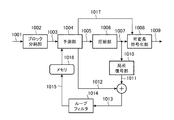
- FIG. 12 is a block diagram showing a configuration of an encoding apparatus according to Non-Patent Document 1.
- an input video signal 1001 to be encoded is divided into units of macroblocks (rectangular blocks of 32 pixels ⁇ 32 lines corresponding to luminance signals) in a block dividing unit 1002 and encoded.
- the converted video signal 1003 is input to the prediction unit 1004.
- the prediction unit 1004 predicts the image signal of each color component in the macroblock between frames and between frames to obtain a prediction error signal 1005.
- a prediction error signal 1005 is obtained by taking the difference from the normalized video signal 1003.
- Non-Patent Document 3 proposes a method for diversifying the division shape of the motion prediction area while maintaining the size of the macroblock at 16 ⁇ 16 pixels with respect to the conventional macroblock.
- the compression unit 1006 performs DCT (Discrete Cosine Transform) processing on the prediction error signal 1005 while changing the block size in accordance with the size of the motion vector allocation unit region, removes the signal correlation, and then quantizes the prediction error signal 1005. Thus, compressed data 1007 is obtained.
- the compressed data 1007 is entropy-encoded by the variable-length encoding unit 1008 and output as a bit stream 1009 and sent to the local decoding unit 1010 to obtain a decoded prediction error signal 1011.
- DCT Discrete Cosine Transform
- the decoded prediction error signal 1011 is added to the prediction signal 1012 used to generate the prediction error signal 1005 to obtain a decoded signal 1013, which is input to the loop filter 1014.
- the decoded signal 1013 is stored in the memory 1016 as a reference image signal 1015 for generating a subsequent prediction signal 1012 after the processing for removing block distortion is performed by the loop filter 1014.
- the prediction signal generation parameter 1017 determined by the prediction unit 1004 in order to obtain the prediction signal 1012 is sent to the variable length coding unit 1008, multiplexed with the bit stream 1009, and output.
- the prediction signal generation parameter 1017 includes, for example, information such as an intra prediction mode indicating how to perform spatial prediction within a frame and a motion vector indicating a motion amount between frames.
- Non-Patent Document 1 discloses a macroblock size of 32 ⁇ 32 pixel blocks (super macroblock: SMB). ) Is used.
- FIG. 13 shows how the motion vector allocation region is divided when performing motion compensation prediction for each M ⁇ M pixel macroblock.
- FIG. 13A shows SMB of Non-Patent Document 1
- FIG. Conventional MPEG-4 AVC / H. H.264 see Non-Patent Document 2.
- Non-Patent Document 1 when the size of the divided shape is larger than (M / 2) ⁇ (M / 2), the DCT block size is set to 16 ⁇ 16 pixels, and correlation between images in a wide area is collectively performed. It is configured to be removed. This increases the compression efficiency of the prediction error signal.
- the macroblock size is expanded to increase the motion vector allocation unit to reduce the amount of parameter code required for prediction, or between signal pixels.
- the correlation has been removed to increase the compression efficiency of the prediction error signal.
- applying a large DCT block size entails an increase in the number of effective bits required for expressing transform coefficients, leading to an increase in the number of coefficient expression bits.
- the present invention has been made to solve the above-described problems, has a good mounting load balance, and better removes signal correlation according to the statistical and local properties of the video signal to be encoded.
- a video encoding apparatus and method thereof and a video decoding apparatus and method thereof, which realizes a video encoding method that performs efficient information compression and enhances the optimality for encoding an ultra-high definition video signal. For the purpose.
- a video encoding device includes: a block dividing unit that divides each frame of an input moving image signal into macroblocks of a predetermined size and outputs the macroblock images; a frame memory that stores reference images; An inter-frame prediction unit that performs inter-frame prediction based on a memory reference image and a macro-block image to generate a prediction image, and outputs information specifying the inter-frame prediction method as inter-frame prediction information; and a macro A prediction unit that subtracts a prediction image from a block image and generates a prediction error signal; a downsampling processing unit that downsamples the prediction error signal and generates a reduced prediction error signal; and converts and quantizes the reduced prediction error signal to quantize A first quantizing transform unit that generates quantized transform coefficients, and inverse quantization / inverse transform of the quantized transform coefficients, and decoding reduction A first inverse quantization conversion unit that generates a measurement error signal, an upsampling processing unit that upsamples the decoded reduced prediction
- the video decoding apparatus includes an entropy decoding unit that entropy-decodes input encoded data and outputs interframe prediction information and quantized transform coefficients included in the encoded data, and a frame that stores a reference image A memory, a first inverse quantization conversion unit that generates a decoded reduced prediction error signal by performing inverse quantization / inverse conversion on the quantized transform coefficient, and upsamples the decoded reduced prediction error signal to generate a decoded prediction error signal.
- An upsampling processing unit a prediction unit that generates a prediction image from a reference image in a frame memory according to inter-frame prediction information, a decoded prediction error signal and a prediction image are added to generate a decoded image, and the decoded image is referred
- an adder that outputs the image to the frame memory.
- the video encoding method includes a block division step for dividing each frame of an input moving image signal into macroblocks of a predetermined size and outputting the macroblock images, and reference images and macros stored in a frame memory.
- An inter-frame prediction is performed based on the block image to generate a prediction image, and an inter-frame prediction step for outputting information specifying the inter-frame prediction method as inter-frame prediction information, and a prediction image from the macro block image
- First quantization transform step and inverse quantization / inverse transform of quantized transform coefficient for decoding A first inverse quantization transform step for generating a small prediction error signal, an upsampling processing step for upsampling the decoded reduced prediction error signal to generate a decoded prediction error signal, and adding the decoded
- the video decoding method includes: an entropy decoding step for entropy decoding input encoded data and outputting inter-frame prediction information and quantized transform coefficients included in the encoded data; and inverse quantization transform coefficients A first inverse quantization conversion step that performs quantization / inverse conversion and generates a decoded reduced prediction error signal; an upsampling processing step that upsamples the decoded reduced prediction error signal and generates a decoded prediction error signal; According to the prediction information, a prediction step for generating a prediction image from the reference image stored in the frame memory, a decoded prediction error signal and the prediction image are added to generate a decoded image, and the decoded image is output to the frame memory as a reference image And an adding step.
- the prediction error signal is down-sampled, transformed and quantized to generate a quantized transform coefficient
- the quantized transform coefficient is up-sampled and inverse quantized / inverted to generate a decoded prediction error signal.
- FIG. 4 shows a 4: 4: 4 format to be processed by the video encoding device and the video decoding device according to Embodiment 1 of the present invention.
- 1 is a block diagram showing a configuration of a video encoding device according to Embodiment 1.
- FIG. 1 is a block diagram illustrating a configuration of a video decoding device according to Embodiment 1.
- FIG. It is a block diagram which shows the structure of the encoding apparatus by a nonpatent literature 1.
- a state of a divided shape of a motion vector allocation region when motion compensation prediction is performed for each macroblock is shown.
- Embodiment 1 FIG.
- motion compensation prediction processing is performed in accordance with the state of each color component signal for a video encoding device and video decoding device that compress and expand a digital video signal input in 4: 4: 4 format.
- a video encoding device and a video decoding device will be described.
- FIG. 1 shows a 4: 4: 4 format used as an input by the video encoding device and the video decoding device according to Embodiment 1.
- the 4: 4: 4 format refers to a format in which the number of pixels of the three signal components C0, C1, and C2 constituting the color moving image are all the same, as shown in FIG.
- the color space of the three signal components may be RGB or XYZ, or may be luminance / color difference (YUV, YCbCr, or YPbPr).
- 1B has a color space of YUV, YCbCr, or YPbPr, and a color difference signal component with respect to the number of pixels of luminance Y.
- the video encoding device and the video decoding device described below are systems in which the 4: 4: 4 format color space is YUV, YCbCr, or YPbPr, and each color component is regarded as corresponding to a luminance component.
- the description will be limited to. However, it is needless to say that the operation described below can be directly applied to the luminance signal in a video encoding device and a video decoding device targeted for video signals in 4: 2: 0 format.
- the present invention can also be applied to color difference signals in 4: 2: 0 format by halving each size.
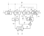
- FIG. 2 is a block diagram showing the configuration of the video encoding device according to the first embodiment.
- the video encoding apparatus shown in FIG. 2 divides a 4: 4: 4 format input video frame into M max ⁇ M max pixel blocks (hereinafter referred to as “reference blocks”), and performs motion prediction in units of the same reference blocks. And the prediction error signal is compressed and encoded.
- reference blocks M max ⁇ M max pixel blocks
- an input video signal (moving image signal) 1 to be encoded is divided into units of a reference block (M pixel ⁇ M line rectangular block) by a block dividing unit 2 to generate an encoded signal (macroblock image) 3.
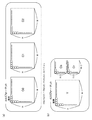
- FIG. 3 shows a reference block generated by the block dividing unit 2.
- the reference block is configured as reference block data of a unit in which rectangular blocks each having M max ⁇ M max pixels are collected.
- the reference block size M max is determined and encoded at a frame or sequence, or an upper layer data level such as GOP (Group Of Pictures). Note that the reference block size Mmax may be changed within the frame, but in this case, the reference block size Mmax is designated in units of a plurality of macroblocks such as slices.
- the reference block data is further divided into “motion prediction unit blocks” of L i ⁇ M i pixel blocks (i: color component identifiers), and motion prediction and encoding are performed based on the motion prediction unit blocks.
- the reference block of each color component in the 4: 4: 4 format is the same for the three color components C0, C1, and C2, and the three color components are used when the size of the reference block is changed. All are changed to the same reference block size.
- Each of the motion prediction unit block sizes L i and M i can be selected for each of the color components C0, C1, and C2, and can be changed in units of sequence, GOP, frame, reference block, and the like. Also good. By adopting such a configuration, it is possible to flexibly determine the motion prediction unit block size according to the difference in the signal properties for each color component without changing the reference block size. In addition, since the size of the reference block is not dynamically changed, it is possible to efficiently implement the coding / decoding process in parallel and pipelined in units of the reference block.
- the prediction unit (inter-frame prediction unit) 4 performs motion compensation prediction on the image signal of each color component in the reference block to generate a prediction signal (prediction image) 12 and a reference image held in the memory (frame memory) 16.
- the prediction error signal 5 is obtained by subtracting the signal from the encoded signal 3.
- the compression unit 6 performs conversion processing such as DCT processing on the prediction error signal 5 to remove the signal correlation, and then quantizes to obtain prediction error compressed data 7.
- the compression unit 6 has a plurality of conversion processing modes that can be applied to the prediction error signal 5, and an optimum mode is selected from these to perform the encoding processing, and the selected mode is the conversion processing mode.
- the information 32 is output to the variable length encoding unit 8.
- the operation of the compression unit 6 is a feature of the video encoding apparatus according to the first embodiment, and will be described in detail later.
- a variable length coding unit (entropy coding unit) 8 entropy codes the prediction error compressed data 7 and outputs it as a bit stream 9.
- the local decoding unit 10 obtains a decoded prediction error signal 11 from the prediction error compressed data 7.
- This decoded prediction error signal 11 is added to the prediction signal 12 used to generate the prediction error signal 5 by the adding unit to become a decoded signal (local decoded image) 13, which is input to the loop filter 14.
- a prediction signal generation parameter (interframe prediction information) 17 determined by the prediction unit 4 to obtain the prediction signal 12 is sent to the variable length coding unit 8 and output as a bit stream 9.
- the prediction signal generation parameter 17 is sent to the variable length coding unit 8 and output as the bit stream 9.
- the contents of the prediction signal generation parameter 17 will be described in detail later together with the description of the prediction unit 4.
- the loop filter 14 performs block distortion correction using the prediction signal generation parameter 17 and the quantization parameter 19 on the decoded signal 13 on which block distortion generated along with transform coefficient quantization in the compression unit 6 is superimposed.
- a reference block is a macroblock
- a method of encoding while selecting intraframe encoding or interframe predictive encoding in units of macroblocks is generally used. is there. This is because when the motion prediction between frames is not sufficient, the use of the correlation within the frame may make the encoding more efficient.
- the description of the intraframe encoding and the selective use thereof will not be specified in the text when explaining the points of the invention, but unless otherwise specified, the reference block The configuration is such that selective use of intra-frame coding in units of.
- the reference block may be defined as a macroblock, but the term “reference block” will be used hereinafter for the description of motion prediction.
- the detailed operation of the prediction unit 4 that is one of the features of the first embodiment will be described below.
- the features of the prediction unit 4 of the first embodiment are the following two points. (1) Linked adaptation of the size of the reference block / motion prediction unit block and the division shape used for motion prediction. (2) Determination of motion prediction mode and motion vector according to the properties of each color component.
- the prediction unit 4 first divides the reference block into motion prediction unit blocks of L i ⁇ M i pixels in accordance with the characteristics of the signals of the respective color components, and further divides the motion prediction unit block into l i ⁇ . Divide into a plurality of shapes consisting of combinations of mi pixels. Then, the prediction unit 4 performs prediction by assigning a unique motion vector to each divided region, selects a shape having the highest prediction efficiency as a motion prediction mode, and uses each resultant divided motion vector as a motion vector. A prediction error signal 5 is obtained by performing a motion prediction on.
- the divided shape in the motion prediction unit block is assumed to be a shape constituted by a combination of “basic blocks” composed of l ⁇ m pixels.
- FIG. 4 shows the basic block division shape determined by these conditions.
- FIG. 4 is an explanatory diagram showing a shape example obtained by dividing the motion prediction unit block by the basic block unit by the prediction unit 4.
- the divided pattern (divided pattern) shown in FIG. 4 may be common to the three color components, or may be configured to be determined independently. Also good.
- the divided patterns mc_mode 0 to 7 are hereinafter referred to as “motion prediction mode”.
- Non-Patent Document 3 discloses a method for diversifying the division shape of a motion prediction application region with respect to a conventional macroblock.
- the division shape is expressed by the intersection position between a line segment for performing macroblock division and its block boundary.
- this method is a method of increasing the division pattern in the reference block while the number of pixels M is fixed, and has the following problems.
- the approach of FIG. 4 in the video encoding apparatus is as follows: 1) The value of M max is set to a higher level such as a frame based on the encoding conditions and the resolution and properties of the video signal. in that a changeable, 2) M max ⁇ be dividable pixel blocks of M max to the basic block L i ⁇ M i pixels according to the characteristics of each color component C i, 3) division condition of basic blocks.
- M max be dividable pixel blocks of M max to the basic block L i ⁇ M i pixels according to the characteristics of each color component C i
- the value of the size M max of the basic block is not changed locally within the frame or slice, but can be changed only at a higher data structure level such as a frame level or a frame sequence (sequence, GOP).
- This mechanism makes it possible to adapt to differences in the meaning of the image signal patterns included in the reference block. For example, the meaning of the signal pattern in the same M max ⁇ M max pixel block is different between a video with a small resolution (Video Graphics Array, VGA, etc.) and a video with a large resolution (HDTV, etc.).
- the processing unit for motion prediction can be optimized according to the signal characteristics of each color component. Furthermore, by providing a limited degree of freedom of the division pattern in the motion prediction unit block as shown in FIG.
- the overall efficiency of motion prediction is suppressed while suppressing the amount of code required for the division pattern representation in the motion prediction unit block. Can be improved. Further, if the process of determining the value of the reference block size Mmax at the frame level is performed efficiently, then the variation of the division pattern to be inspected in the reference block can be reduced as compared with the prior art. The load can be reduced.
- Examples of a method for determining the value of the reference block size M max include the following methods. (1) Determine based on the resolution of the video to be encoded. In the case of the same M max value, when the resolution is high, the image signal pattern in the reference block has a more noise component meaning, and the motion vector becomes difficult to capture the image signal pattern. In such a case, the M max value is increased so that the image signal pattern can be captured. (2) with a small M max value if activity is greater the magnitude of the difference value is regarded as the activity between frames, it is smaller performs motion prediction with a large M max value. In addition, the size control at this time is determined based on the frame rate of the video to be encoded.
- the motion prediction unit block sizes L i and M i are determined for each color component.
- the input video signal 1 is a signal defined in a color space of YUV (or YCbCr or the like)
- the U / V component that is a color signal has a narrower signal band than the luminance signal Y component. Therefore, the intra-block variance is smaller than the luminance.
- an example of a judgment criterion such that the U / V component sizes L i and M i are configured to take values larger than the luminance signal Y component sizes L i and M i can be considered (FIG. 3). reference).
- the video encoding apparatus includes a reference block size determination unit for determining values of M max , L i , and M i and notifying each unit, and a reference block size The structure which determines the information 18 may be sufficient.
- the prediction unit 4 executes a motion detection process using the division patterns of FIGS. 3 and 4 based on the motion prediction unit block sizes L i and M i derived from the reference block size information 18.
- FIG. 5 is a flowchart showing the operation of the prediction unit 4.
- the prediction unit 4 performs motion prediction on the C i component of the frame in units of motion prediction unit blocks of L i ⁇ M i pixels. Basically, in this process, the optimum motion vector for each divided region is detected in the designated motion search range for each of the divided patterns from mc_mode 0 to 7 in FIG. 4, and finally mc_mode 0 for the motion prediction unit block is detected. It is determined which of the motion prediction modes (1) to (7) is the best in prediction efficiency.
- the prediction efficiency is calculated between the total code amount R of the motion vectors in the motion prediction unit block, the prediction signal 12 generated from the reference image stored in the memory 16 by applying the motion vector, and the input video signal 1. It is defined by the following cost J derived from the prediction error amount D.
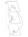
- FIG. 6 illustrates a method for calculating the cost J by taking the case of mc_mode5 as an example.
- the motion prediction unit block to be predicted in the frame F (t) is composed of two divided regions B 0 and B 1 .
- the memory 16 stores two encoded / locally decoded reference images F ′ (t ⁇ 1) and F ′ (t ⁇ 2), and the divided areas B 0 and B 1 are stored in 2 Assume that motion prediction can be performed using the reference images F ′ (t ⁇ 1) and F ′ (t ⁇ 2).
- FIG. 6 illustrates a method for calculating the cost J by taking the case of mc_mode5 as an example.
- the motion prediction unit block to be predicted in the frame F (t) is composed of two divided regions B 0 and B 1 .
- the memory 16 stores two encoded / locally decoded reference images F ′ (t ⁇ 1) and F ′ (t ⁇ 2), and the divided areas B 0 and B 1 are stored in 2 Assume that motion prediction can be performed using
- the divided area B 0 uses the reference image F ′ (t ⁇ 2) to detect a motion vector MV t ⁇ 2 (B 0 ), and the divided area B 1 uses the reference image F ′ (t ⁇ 1).
- the motion vector MV t-1 (B 1 ) is detected.
- v is a motion vector
- the prediction error amount D of the divided area B is the sum of absolute differences (Sum of Absolute Difference, SAD) can be used to calculate the following equation (2).
- MVD (B 0 ) MV t ⁇ 2 (B 0 ) ⁇ PMV (B 0 ) (3)
- MVD (B 1 ) MV t ⁇ 1 (B 1 ) ⁇ PMV (B 1 )
- the prediction unit 4 calculates the cost J for all motion vectors to be inspected within the search range, and obtains a solution having the smallest cost J as the division pattern of mc_mode5.
- Mc_mode7 for further l i ⁇ m i pixel block configured to select a mode of mc_mode0 ⁇ 7.
- the name of the mode at this time is sub_mc_mode 0 to 7 for convenience.
- the processing for determining sub_mc_mode for l i ⁇ m i pixel blocks is based on the processing flow of FIG. 5, and the cost J 7 of mc_mode 7 corresponding to the L i ⁇ M i pixel block unit is l i ⁇ m i pixels.
- the total cost obtained using sub_mc_mode determined in block units.
- step ST2 “Yes” the prediction unit 4 outputs the motion prediction mode, the motion vector, and the prediction error signal 5 that have been held so far as a final solution (step ST5). ). Otherwise (step ST2 “No” or step ST4 “No”), the variable k is incremented in step ST6, and the process returns to step ST1 to verify the next motion prediction mode.
- the prediction error signal 5 and the prediction signal generation parameter 17 are output, and these are entropy encoded by the variable length encoding unit 8.
- the features of the compression unit 6 and the local decoding unit 10 according to the first embodiment are as follows. (1) Switching between transformation / inverse transformation processing according to the shape of the motion vector allocation area. (2) Application of variable resolution conversion / inverse conversion processing.
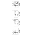
- FIG. 8 is a block diagram showing an internal configuration of the compression unit 6 according to the first embodiment.
- the compression unit 6 receives the prediction error signal 5, performs a conversion process to remove the correlation between the pixels, performs quantization, and quantizes coefficient data 7 a and 7 b (prediction error compression data) multiplexed in the bit stream 9. 7). Since the above features (1) and (2) are provided, the conversion processing determination unit 31 first selects a conversion processing method. This process is performed with reference to the motion prediction mode included in the prediction signal generation parameter 17.
- the conversion process determining unit 31 sets the unit for performing the conversion process to (m / 2) ⁇ (l / 2) pixel blocks, and for each motion vector allocation region
- a means having a high coding efficiency (the coding distortion is small if the code amount is the same, and the code quantity is small if the coding code is the same) is selected from the following two options (a) and (b). This can be achieved, for example, by evaluating the results of actually trying two options.
- A The motion vector allocation area is equally divided into (m / 2) ⁇ (l / 2) pixel blocks, and transformation and quantization are performed respectively.
- the motion vector allocation region is equally divided into m ⁇ l pixel blocks, and each is horizontally down-sampled to generate (m / 2) ⁇ (l / 2) pixel blocks. Conversion and quantization.
- the conversion process determining unit 31 outputs the selection result to the switch (conversion selection switch, SW) 33 as conversion process mode information 32.
- the switch 33 switches the conversion processing method for each motion vector allocation area according to the conversion processing mode information 32.
- the conversion processing mode information 32 is the content for selecting the option (a)
- the prediction error signal 5 of each motion vector assignment region is directly input to the conversion unit 34, and (m / 2) ⁇ (l / 2) pixel block.
- the result is quantized by the quantizing unit 35 and output as quantized coefficient data 7a. Note that the conversion unit 34 and the quantization unit 35 shown in the upper part of FIG. 8 are combined to form a second quantization conversion unit.
- the prediction error signal 5 of each motion vector allocation region is first input to the downsampling processing unit 36 for each m ⁇ l block. Reduction conversion is performed to (m / 2) ⁇ (l / 2) pixel blocks. Next, the same conversion unit 34 and quantization unit 35 as those used in option (a) are transformed and quantized and output as quantized coefficient data 7b. In addition, the conversion unit 34 and the quantization unit 35 shown in the lower part of FIG. 8 are combined to form a first quantization conversion unit.
- the downsampling processing unit 36 performs pixel thinning by applying a downsampling filter that is designed in accordance with the nature of the prediction error signal 5.
- the downsampling filter may be arbitrarily selected by applying a linear low-pass filter such as the following equation (4) in the horizontal and vertical directions, or by extracting only the low-frequency component by applying wavelet transform. .
- a method for transmitting to the video decoding device which one of the quantized coefficient data 7a and 7b is to be selected as the quantized coefficient data of the prediction error compressed data 7 is that the conversion processing mode information 32 is transmitted to the variable length encoding unit 8. This is realized by outputting and multiplexing the information into the bit stream 9.
- the conversion process determination unit 31 selects the above options (a) and (b) only for a larger area where the motion vector allocation area is not an m ⁇ 1 pixel block.
- the option (a) is always selected.
- the option (a) is effective when the motion prediction is lost and the prediction error signal distribution in the motion vector allocation region is not uniform (large variance)
- the option (b) is effective for motion prediction and the motion vector. This is effective when the prediction error signal distribution in the allocation region is uniform (small variance).
- Non-Patent Document 1 in order to improve the coding efficiency for the case of option (b), direct DCT for a 16 ⁇ 16 pixel block, that is, the DCT processing target block itself is used for a motion prediction block larger than 16 ⁇ 16 pixels. Suggests size expansion. However, DCT with a large block size has a problem that the number of bits required for coefficient expression increases and affects the hardware cost of the conversion process itself.
- the (m / 2) ⁇ (l / 2) pixel block corresponds to the minimum motion vector allocation region size in the case of sub_mc_mode7.
- the transform / quantization process can always be limited to only a process targeting (m / 2) ⁇ (l / 2) pixels, and the number of coefficients to be encoded However, it is possible to perform encoding while suppressing the number of bits necessary for coefficient expression.
- FIG. 9 shows the internal configuration of local decoding section 10 in the first embodiment.
- the local decoding unit 10 receives the quantized coefficient data 7 and the conversion processing mode information 32 as input, and a switch (conversion selection switch, SW) 37 follows the instructions of the conversion processing mode information 32 to quantize the prediction coefficient compressed data 7. Determining which of the above options (a) and (b) the data was encoded by the compression unit 6 and switching the process, decoding by performing inverse quantization and inverse transform in a method suitable for each process The prediction error signals 11a and 11b are restored.
- a switch conversion selection switch
- the conversion processing mode information 32 indicates the option (a)
- the quantized coefficient data of the prediction error compressed data 7 is the quantized coefficient data 7a shown in FIG. 8 (m / 2)
- Each of the ⁇ (l / 2) pixel blocks is inversely quantized and inversely transformed by the inverse quantization unit 38 and the inverse transformation unit 39 to obtain a decoded prediction error signal 11a.
- the inverse quantization unit 38 and the inverse transform unit 39 shown in the upper part of FIG. 9 are combined to form a second inverse quantization transform unit.
- the conversion processing mode information 32 indicates that the option (b) is selected, it is determined that the quantized coefficient data of the prediction error compressed data 7 is the quantized coefficient data 7b shown in FIG.
- the same inverse quantization unit 38 and inverse transform unit 39 as those used in (a) are subjected to inverse quantization and inverse transform, respectively, and the decoded prediction pixel value 40 in units of (m / 2) ⁇ (l / 2) pixel blocks is obtained. obtain. Then, the upsampling processing unit 41 applies a linear interpolation filter to the decoded prediction pixel value 40 of the (m / 2) ⁇ (l / 2) pixel block to generate a decoded prediction error signal 11b including the m ⁇ l pixel block. Generate. Note that the inverse quantization unit 38 and the inverse transform unit 39 shown in the lower part of FIG. 9 are combined to form a first inverse quantization transform unit.
- the input video signal 1 is encoded by the video encoding device of FIG. 2 based on the above processing, and is video as a bitstream 9 in a unit (hereinafter referred to as a slice) in which a plurality of reference blocks are bundled.
- FIG. 10 shows a data array of the bit stream 9.
- the bit stream 9 is configured as a collection of encoded data for the number of reference blocks included in a frame, and the reference blocks are unitized in units of slices.
- a picture level header to which reference blocks belonging to the same frame refer as a common parameter is prepared, and reference block size information 18 is stored in the picture level header. If the reference block size M max is fixed in sequence units higher than the picture level, the reference block size information 18 may be multiplexed in the sequence level header.
- the reference block data includes a reference block header and prediction error compression data.
- the reference block header includes a motion prediction mode mc_mode and a motion vector (corresponding to the prediction signal generation parameter 17) corresponding to the motion prediction unit block in the reference block.
- the quantization parameter 19 used for generating the prediction error compression data 7 is arranged.
- the type of mc_mode 0 to 7 is encoded. If the type is mc_mode 0 to 6, the motion vector information corresponding to the motion vector allocation region specified in the motion prediction mode is encoded. If the type is mc_mode7, sub_mc_mode is encoded for each basic block.
- the quantization parameter 19 for each reference block is multiplexed, and the prediction error compressed data 7 (corresponding to the quantized coefficient data 7a and 7b) output from the compression unit 6 is multiplexed.
- the prediction error compression data 7 (quantized coefficient data 7a, 7b) is encoded before the prediction error compression data by the compression unit 6 and the local decoding.
- the conversion processing mode information 32 is multiplexed as information indicating whether processing has been performed with any of the options (a) and (b) in the unit 10.
- the reference block size determining unit is configured so that the size L i and M i of the motion prediction unit block used in each reference block can be selected for each reference block.
- the size may be multiplexed in each reference block header.
- the size of the motion prediction unit block can be changed according to the nature of the local image signal, It becomes possible to perform motion prediction with higher adaptability.
- Information indicating whether to be multiplexed on each reference block header or fixedly multiplexed on a higher level header such as a sequence, GOP, picture, slice, etc.
- identification information in an upper level header such as a sequence, GOP, picture, slice, etc. As long as it is multiplexed. As a result, if there is little influence on the motion prediction performance even if it is fixed at a higher level, the overhead for encoding the sizes L i and M i of the motion prediction unit block is reduced for each reference block, and efficient coding is performed. Is possible.
- FIG. 11 is a block diagram showing the configuration of the video decoding device according to the first embodiment.
- the variable length decoding unit (entropy decoding unit) 100 receives the bitstream 9 shown in FIG. 10, decodes the sequence level header, and then decodes the picture level header to decode the reference block size information.
- the reference block size M max and the motion prediction unit block sizes L i and M i used in the picture are recognized, and the reference block size information 18 is notified to the prediction error decoding unit 101 and the prediction unit 102.
- variable-length decoding unit 100 uses the motion prediction unit block sizes L i and M i. Is decoded in each reference block header, and the sizes L i and M i of the motion prediction unit blocks are recognized by decoding each reference block header based on the identification information. To be configured.
- the reference block data is first decoded from the reference block header. Subsequently, the motion prediction mode to be applied per motion prediction unit block is decoded.
- the motion prediction mode first, mc_mode is decoded in units of motion prediction unit blocks. In the case of mc_mode7, sub_mc_mode is decoded for each basic block, and in other cases, motion vectors are decoded by the number of motion vector allocation regions, and further, quantization parameter 19 and conversion processing mode information 32 for each reference block. The information such as the prediction error compressed data 7 is sequentially decoded.
- the prediction error compression data 7, the quantization parameter 19, and the transformation processing mode information 32 are input to the prediction error decoding unit 101 and restored to the decoded prediction error signal 11.
- the prediction error decoding unit 101 performs processing equivalent to the local decoding unit 10 in the video encoding device in FIG. 2 based on the decoded conversion processing mode information 32. That is, the prediction error decoding unit 101 includes a switch 37, an inverse quantization unit 38, an inverse conversion unit 39, and an upsampling processing unit 41 illustrated in FIG. 9, and the switch 37 sets the upsampling processing unit 41 according to the conversion processing mode information 32. Select whether or not to go through, and perform inverse quantization and inverse transform.
- the prediction unit 102 generates the prediction signal 12 from the prediction signal generation parameter 17 decoded by the variable length decoding unit 100 and the reference image signal 15 in the memory 103.
- the prediction unit 102 performs processing equivalent to the prediction unit 4 in the video encoding device, but does not include a motion vector detection operation.
- the motion prediction mode is one of mc_modes 0 to 7 shown in FIG. 4, and the prediction unit 102 generates a decoded signal (decoded image) 13 using a motion vector assigned to each basic block based on the divided shape.
- the decoded prediction error signal 11 and the prediction signal 12 are added by the adder and input to the loop filter 104 as the decoded signal 13.
- the decoded signal 13 is subjected to processing for removing coding noise by the loop filter 104 and then stored in the memory 103 as a reference image signal 15 for generating the subsequent prediction signal 12.
- the video encoding device divides each frame of the input video signal 1 that is input into macroblocks of a predetermined size and outputs the result as the encoded signal 3, Based on the memory 16 that stores the reference image signal 15, the reference image signal 15 in the memory 16, and the encoded signal 3, the inter-frame prediction is performed to generate the prediction signal 12, and the inter-frame prediction method is specified.
- the information is output as the prediction signal generation parameter 17 and the prediction signal 12 is subtracted from the encoded signal 3 to generate the prediction error signal 5.
- the prediction error signal 5 is downsampled and the reduced prediction error signal is generated.
- a down-sampling processing unit 36 that generates a conversion prediction signal, a conversion unit 34 that converts the reduced prediction error signal, a quantization unit 35 that quantizes, and a quantization coefficient data output from the quantization unit 35
- Up-sampling processing for generating a decoded prediction error signal 11b by up-sampling the decoded prediction pixel value 40 output from the inverse transformation unit 39, the inverse transformation unit 39 for inverse transformation, and the inverse transformation unit 39.
- Unit 41 an addition unit that adds decoded prediction error signal 11b and prediction signal 12 to generate decoded signal 13, and outputs this decoded signal 13 to memory 16 as a reference image, quantized coefficient data 7b, and prediction signal
- the generation parameter 17 is entropy-encoded, and the variable-length encoding unit 8 that outputs the bit stream 9 is provided.
- the downsampling processing unit 36, the conversion unit 34, the quantization unit 35, the inverse quantization unit 38, the inverse transformation unit 39, and the upsampling processing unit 41 are used, or the conversion unit 34, the quantization unit 35, and the inverse quantization unit.
- the prediction error signal is reduced in resolution by converting the resolution in units of blocks, and then encoded by performing conversion, quantization, inverse quantization, and inverse conversion to perform resolution conversion and enlargement. Efficiency can be increased and the circuit scale can be reduced. Therefore, in order to efficiently encode the 4: 4: 4 format color video signal, the encoding of the prediction error signal 5 generated as a result of the motion prediction is performed even when the motion vector allocation area of the motion compensation prediction is large. Can be implemented efficiently in accordance with the signal distribution state, while suppressing the mounting load, and a video encoding apparatus that can maintain encoding quality even at a high compression rate can be provided at low cost.
- the video decoding apparatus performs entropy decoding on the input bit stream 9 and outputs the prediction signal generation parameter 17 and the quantized coefficient data included in the bit stream 9.
- Unit 100 memory 103 that stores reference image signal 15, inverse quantization unit 38 that inversely quantizes quantized coefficient data, inverse transform unit 39 that performs inverse transform, and decoded prediction pixel value output by inverse transform unit 39 40, up-sampling processing unit 41 for generating decoded prediction error signal 11b, prediction unit 102 for generating prediction signal 12 from reference image signal 15 in memory 103 according to prediction signal generation parameter 17, and decoded prediction
- the error signal 11b and the prediction signal 12 are added to generate a decoded signal 13, and this decoded signal 13 is referred to as a reference image signal 15 and Configured as an adding section for outputting to the memory 103 Te.
- a switch 37 for selecting whether to use the inverse quantization unit 38, the inverse transformation unit 39, and the upsampling processing unit 41 or to use the inverse quantization unit 38 and the inverse transformation unit 39 according to the decoded transformation processing mode information 32 is provided. It was configured to provide. Therefore, it is possible to provide a video decoding device corresponding to the video encoding device.
- the encoding / decoding process according to the present invention uses the conventional luminance / chrominance component format.
- video coding for 4: 2: 0 or 4: 2: 2 format that has been subjected to color thinning in the above
- the present invention can also be applied to the case of encoding / decoding in units of reference blocks such as macroblocks. Needless to say.
- the video encoding device, video decoding device, video encoding method, and video decoding method have a good implementation load balance and better remove signal correlation according to the statistical and local characteristics of the video signal to be encoded. Therefore, the present invention is suitable for use in encoding a 4: 4: 4 format ultra-high definition video signal.
Landscapes
- Engineering & Computer Science (AREA)
- Multimedia (AREA)
- Signal Processing (AREA)
- Computing Systems (AREA)
- Theoretical Computer Science (AREA)
- Compression Or Coding Systems Of Tv Signals (AREA)
- Compression, Expansion, Code Conversion, And Decoders (AREA)
Abstract
Priority Applications (5)
| Application Number | Priority Date | Filing Date | Title |
|---|---|---|---|
| EP10780283A EP2437499A4 (fr) | 2009-05-29 | 2010-05-27 | Codeur et décodeur vidéo, procédé de codage et décodage vidéo |
| US13/322,860 US20120076203A1 (en) | 2009-05-29 | 2010-05-27 | Video encoding device, video decoding device, video encoding method, and video decoding method |
| CN2010800238927A CN102450018A (zh) | 2009-05-29 | 2010-05-27 | 影像编码装置、影像解码装置、影像编码方法及影像解码方法 |
| BRPI1011333A BRPI1011333A2 (pt) | 2009-05-29 | 2010-05-27 | dispositivo de codificação e de decodificação de vídeo, e, métodos de codificação e de decodificação de vídeo |
| JP2011515898A JPWO2010137323A1 (ja) | 2009-05-29 | 2010-05-27 | 映像符号化装置、映像復号装置、映像符号化方法、および映像復号方法 |
Applications Claiming Priority (2)
| Application Number | Priority Date | Filing Date | Title |
|---|---|---|---|
| JP2009-130459 | 2009-05-29 | ||
| JP2009130459 | 2009-05-29 |
Publications (1)
| Publication Number | Publication Date |
|---|---|
| WO2010137323A1 true WO2010137323A1 (fr) | 2010-12-02 |
Family
ID=43222449
Family Applications (1)
| Application Number | Title | Priority Date | Filing Date |
|---|---|---|---|
| PCT/JP2010/003552 WO2010137323A1 (fr) | 2009-05-29 | 2010-05-27 | Codeur et décodeur vidéo, procédé de codage et décodage vidéo |
Country Status (6)
| Country | Link |
|---|---|
| US (1) | US20120076203A1 (fr) |
| EP (1) | EP2437499A4 (fr) |
| JP (1) | JPWO2010137323A1 (fr) |
| CN (1) | CN102450018A (fr) |
| BR (1) | BRPI1011333A2 (fr) |
| WO (1) | WO2010137323A1 (fr) |
Cited By (3)
| Publication number | Priority date | Publication date | Assignee | Title |
|---|---|---|---|---|
| JP2015508250A (ja) * | 2012-01-19 | 2015-03-16 | マグナム セミコンダクター, インコーポレイテッド | 適応低解像度アップデートモードを提供するための方法および機器 |
| JP5902814B2 (ja) * | 2012-07-09 | 2016-04-13 | 日本電信電話株式会社 | 映像符号化方法および装置、映像復号方法および装置、及びそれらのプログラム |
| US10531094B2 (en) | 2014-01-09 | 2020-01-07 | Hitachi Kokusai Electric Inc. | Image processing device and moving image transmission method |
Families Citing this family (59)
| Publication number | Priority date | Publication date | Assignee | Title |
|---|---|---|---|---|
| CN103038783B (zh) * | 2010-03-09 | 2016-03-09 | 泰景系统公司 | 自适应视频解码电路及其方法 |
| US9601692B1 (en) | 2010-07-13 | 2017-03-21 | Crossbar, Inc. | Hetero-switching layer in a RRAM device and method |
| US8946046B1 (en) | 2012-05-02 | 2015-02-03 | Crossbar, Inc. | Guided path for forming a conductive filament in RRAM |
| US9012307B2 (en) | 2010-07-13 | 2015-04-21 | Crossbar, Inc. | Two terminal resistive switching device structure and method of fabricating |
| US9570678B1 (en) | 2010-06-08 | 2017-02-14 | Crossbar, Inc. | Resistive RAM with preferental filament formation region and methods |
| WO2011156787A2 (fr) | 2010-06-11 | 2011-12-15 | Crossbar, Inc. | Structure de pilier pour dispositif de mémoire et procédé |
| US8374018B2 (en) | 2010-07-09 | 2013-02-12 | Crossbar, Inc. | Resistive memory using SiGe material |
| US8168506B2 (en) | 2010-07-13 | 2012-05-01 | Crossbar, Inc. | On/off ratio for non-volatile memory device and method |
| US8884261B2 (en) | 2010-08-23 | 2014-11-11 | Crossbar, Inc. | Device switching using layered device structure |
| US8569172B1 (en) | 2012-08-14 | 2013-10-29 | Crossbar, Inc. | Noble metal/non-noble metal electrode for RRAM applications |
| US8947908B2 (en) | 2010-11-04 | 2015-02-03 | Crossbar, Inc. | Hetero-switching layer in a RRAM device and method |
| US8492195B2 (en) | 2010-08-23 | 2013-07-23 | Crossbar, Inc. | Method for forming stackable non-volatile resistive switching memory devices |
| US8889521B1 (en) | 2012-09-14 | 2014-11-18 | Crossbar, Inc. | Method for silver deposition for a non-volatile memory device |
| US9401475B1 (en) | 2010-08-23 | 2016-07-26 | Crossbar, Inc. | Method for silver deposition for a non-volatile memory device |
| US8558212B2 (en) | 2010-09-29 | 2013-10-15 | Crossbar, Inc. | Conductive path in switching material in a resistive random access memory device and control |
| US8502185B2 (en) | 2011-05-31 | 2013-08-06 | Crossbar, Inc. | Switching device having a non-linear element |
| USRE46335E1 (en) | 2010-11-04 | 2017-03-07 | Crossbar, Inc. | Switching device having a non-linear element |
| US8930174B2 (en) | 2010-12-28 | 2015-01-06 | Crossbar, Inc. | Modeling technique for resistive random access memory (RRAM) cells |
| US9153623B1 (en) | 2010-12-31 | 2015-10-06 | Crossbar, Inc. | Thin film transistor steering element for a non-volatile memory device |
| US8815696B1 (en) | 2010-12-31 | 2014-08-26 | Crossbar, Inc. | Disturb-resistant non-volatile memory device using via-fill and etchback technique |
| US9620206B2 (en) | 2011-05-31 | 2017-04-11 | Crossbar, Inc. | Memory array architecture with two-terminal memory cells |
| US8619459B1 (en) | 2011-06-23 | 2013-12-31 | Crossbar, Inc. | High operating speed resistive random access memory |
| US8946669B1 (en) | 2012-04-05 | 2015-02-03 | Crossbar, Inc. | Resistive memory device and fabrication methods |
| US9627443B2 (en) | 2011-06-30 | 2017-04-18 | Crossbar, Inc. | Three-dimensional oblique two-terminal memory with enhanced electric field |
| US9564587B1 (en) | 2011-06-30 | 2017-02-07 | Crossbar, Inc. | Three-dimensional two-terminal memory with enhanced electric field and segmented interconnects |
| US9166163B2 (en) | 2011-06-30 | 2015-10-20 | Crossbar, Inc. | Sub-oxide interface layer for two-terminal memory |
| CN103828047A (zh) | 2011-07-22 | 2014-05-28 | 科洛斯巴股份有限公司 | 用于非易失性存储器装置的p+硅锗材料的种子层及方法 |
| US10056907B1 (en) | 2011-07-29 | 2018-08-21 | Crossbar, Inc. | Field programmable gate array utilizing two-terminal non-volatile memory |
| US8674724B2 (en) | 2011-07-29 | 2014-03-18 | Crossbar, Inc. | Field programmable gate array utilizing two-terminal non-volatile memory |
| US9729155B2 (en) | 2011-07-29 | 2017-08-08 | Crossbar, Inc. | Field programmable gate array utilizing two-terminal non-volatile memory |
| US20130117418A1 (en) * | 2011-11-06 | 2013-05-09 | Akamai Technologies Inc. | Hybrid platform for content delivery and transcoding |
| US9491475B2 (en) | 2012-03-29 | 2016-11-08 | Magnum Semiconductor, Inc. | Apparatuses and methods for providing quantized coefficients for video encoding |
| US9087576B1 (en) | 2012-03-29 | 2015-07-21 | Crossbar, Inc. | Low temperature fabrication method for a three-dimensional memory device and structure |
| US9685608B2 (en) | 2012-04-13 | 2017-06-20 | Crossbar, Inc. | Reduced diffusion in metal electrode for two-terminal memory |
| US8658476B1 (en) | 2012-04-20 | 2014-02-25 | Crossbar, Inc. | Low temperature P+ polycrystalline silicon material for non-volatile memory device |
| US8796658B1 (en) | 2012-05-07 | 2014-08-05 | Crossbar, Inc. | Filamentary based non-volatile resistive memory device and method |
| KR101347062B1 (ko) * | 2012-06-27 | 2014-01-10 | 숭실대학교산학협력단 | 움직임 벡터의 예측을 위한 탐색영역 설정 장치 및 방법 |
| US9583701B1 (en) | 2012-08-14 | 2017-02-28 | Crossbar, Inc. | Methods for fabricating resistive memory device switching material using ion implantation |
| US9741765B1 (en) | 2012-08-14 | 2017-08-22 | Crossbar, Inc. | Monolithically integrated resistive memory using integrated-circuit foundry compatible processes |
| US8946673B1 (en) | 2012-08-24 | 2015-02-03 | Crossbar, Inc. | Resistive switching device structure with improved data retention for non-volatile memory device and method |
| US9312483B2 (en) | 2012-09-24 | 2016-04-12 | Crossbar, Inc. | Electrode structure for a non-volatile memory device and method |
| US9576616B2 (en) | 2012-10-10 | 2017-02-21 | Crossbar, Inc. | Non-volatile memory with overwrite capability and low write amplification |
| US8982647B2 (en) | 2012-11-14 | 2015-03-17 | Crossbar, Inc. | Resistive random access memory equalization and sensing |
| US9412790B1 (en) | 2012-12-04 | 2016-08-09 | Crossbar, Inc. | Scalable RRAM device architecture for a non-volatile memory device and method |
| JP6151909B2 (ja) | 2012-12-12 | 2017-06-21 | キヤノン株式会社 | 動画像符号化装置、方法およびプログラム |
| US9406379B2 (en) | 2013-01-03 | 2016-08-02 | Crossbar, Inc. | Resistive random access memory with non-linear current-voltage relationship |
| US9324942B1 (en) | 2013-01-31 | 2016-04-26 | Crossbar, Inc. | Resistive memory cell with solid state diode |
| US9112145B1 (en) | 2013-01-31 | 2015-08-18 | Crossbar, Inc. | Rectified switching of two-terminal memory via real time filament formation |
| US9392286B2 (en) | 2013-03-15 | 2016-07-12 | Magnum Semiconductor, Inc. | Apparatuses and methods for providing quantized coefficients for video encoding |
| US9794575B2 (en) | 2013-12-18 | 2017-10-17 | Magnum Semiconductor, Inc. | Apparatuses and methods for optimizing rate-distortion costs in video encoding |
| US9485456B2 (en) | 2013-12-30 | 2016-11-01 | Akamai Technologies, Inc. | Frame-rate conversion in a distributed computing system |
| US10290801B2 (en) | 2014-02-07 | 2019-05-14 | Crossbar, Inc. | Scalable silicon based resistive memory device |
| FR3033114A1 (fr) * | 2015-02-19 | 2016-08-26 | Orange | Procede de codage et decodage d'images, dispositif de codage et decodage et programmes d'ordinateur correspondants |
| US10542277B2 (en) * | 2017-10-24 | 2020-01-21 | Arm Limited | Video encoding |
| US11070837B2 (en) | 2018-04-02 | 2021-07-20 | Panasonic Intellectual Property Corporation Of America | Encoding method, decoding method, encoder, and decoder |
| CN108848381B (zh) * | 2018-06-20 | 2021-09-24 | 腾讯科技(深圳)有限公司 | 视频编码方法、解码方法、装置、计算机设备及存储介质 |
| CN117834873A (zh) * | 2019-04-16 | 2024-04-05 | 松下电器(美国)知识产权公司 | 编码装置、解码装置、编码方法、解码方法和记录介质 |
| CN113329228B (zh) * | 2021-05-27 | 2024-04-26 | 杭州网易智企科技有限公司 | 视频编码方法、解码方法、装置、电子设备及存储介质 |
| CN116506628B (zh) * | 2023-06-27 | 2023-10-24 | 苇创微电子(上海)有限公司 | 一种基于像素块的编码预测器方法、编码系统及编码装置 |
Citations (4)
| Publication number | Priority date | Publication date | Assignee | Title |
|---|---|---|---|---|
| JPH10191351A (ja) * | 1996-10-24 | 1998-07-21 | Fujitsu Ltd | 動画像符号化装置および復号化装置 |
| WO1999022525A1 (fr) * | 1997-10-23 | 1999-05-06 | Mitsubishi Denki Kabushiki Kaisha | Procede de codage d'images, codeur d'images, procede de decodage d'images, decodeur d'images |
| JP2002118849A (ja) * | 2000-10-06 | 2002-04-19 | Nec Corp | 動画像符号化方法、動画像符号化装置、動画像復号化装置及びそれらを備えた動画像通信システム |
| JP2007528675A (ja) * | 2004-03-09 | 2007-10-11 | トムソン リサーチ ファンディング コーポレイション | Avc用解像度低下更新モード |
Family Cites Families (2)
| Publication number | Priority date | Publication date | Assignee | Title |
|---|---|---|---|---|
| JP3844844B2 (ja) * | 1997-06-06 | 2006-11-15 | 富士通株式会社 | 動画像符号化装置及び動画像符号化方法 |
| US8391368B2 (en) * | 2005-04-08 | 2013-03-05 | Sri International | Macro-block based mixed resolution video compression system |
-
2010
- 2010-05-27 CN CN2010800238927A patent/CN102450018A/zh active Pending
- 2010-05-27 US US13/322,860 patent/US20120076203A1/en not_active Abandoned
- 2010-05-27 WO PCT/JP2010/003552 patent/WO2010137323A1/fr active Application Filing
- 2010-05-27 BR BRPI1011333A patent/BRPI1011333A2/pt not_active IP Right Cessation
- 2010-05-27 EP EP10780283A patent/EP2437499A4/fr not_active Withdrawn
- 2010-05-27 JP JP2011515898A patent/JPWO2010137323A1/ja active Pending
Patent Citations (4)
| Publication number | Priority date | Publication date | Assignee | Title |
|---|---|---|---|---|
| JPH10191351A (ja) * | 1996-10-24 | 1998-07-21 | Fujitsu Ltd | 動画像符号化装置および復号化装置 |
| WO1999022525A1 (fr) * | 1997-10-23 | 1999-05-06 | Mitsubishi Denki Kabushiki Kaisha | Procede de codage d'images, codeur d'images, procede de decodage d'images, decodeur d'images |
| JP2002118849A (ja) * | 2000-10-06 | 2002-04-19 | Nec Corp | 動画像符号化方法、動画像符号化装置、動画像復号化装置及びそれらを備えた動画像通信システム |
| JP2007528675A (ja) * | 2004-03-09 | 2007-10-11 | トムソン リサーチ ファンディング コーポレイション | Avc用解像度低下更新モード |
Non-Patent Citations (3)
| Title |
|---|
| S.KONDO; H.SASAI: "A Motion Compensation Technique using Sliced Blocks and its Application to Hybrid Video Coding", VCIP 2005, July 2005 (2005-07-01) |
| See also references of EP2437499A4 * |
| SIWEI MA; C.-C. JAY KUO: "High-definition Video Coding with Super-macroblocks", PROC. SPIE, vol. 6508, 2007, pages 650816 |
Cited By (3)
| Publication number | Priority date | Publication date | Assignee | Title |
|---|---|---|---|---|
| JP2015508250A (ja) * | 2012-01-19 | 2015-03-16 | マグナム セミコンダクター, インコーポレイテッド | 適応低解像度アップデートモードを提供するための方法および機器 |
| JP5902814B2 (ja) * | 2012-07-09 | 2016-04-13 | 日本電信電話株式会社 | 映像符号化方法および装置、映像復号方法および装置、及びそれらのプログラム |
| US10531094B2 (en) | 2014-01-09 | 2020-01-07 | Hitachi Kokusai Electric Inc. | Image processing device and moving image transmission method |
Also Published As
| Publication number | Publication date |
|---|---|
| EP2437499A1 (fr) | 2012-04-04 |
| CN102450018A (zh) | 2012-05-09 |
| JPWO2010137323A1 (ja) | 2012-11-12 |
| BRPI1011333A2 (pt) | 2016-03-08 |
| EP2437499A4 (fr) | 2013-01-23 |
| US20120076203A1 (en) | 2012-03-29 |
Similar Documents
| Publication | Publication Date | Title |
|---|---|---|
| WO2010137323A1 (fr) | Codeur et décodeur vidéo, procédé de codage et décodage vidéo | |
| JP6667609B2 (ja) | 画像符号化装置、画像符号化方法、画像復号装置および画像復号方法 | |
| JP6347860B2 (ja) | 画像復号装置、画像復号方法、画像符号化装置および画像符号化方法 | |
| JP5289440B2 (ja) | 画像符号化装置、画像復号装置、画像符号化方法及び画像復号方法 | |
| JP5551837B2 (ja) | 画像復号装置、画像符号化装置、画像復号方法及び画像符号化方法 | |
| WO2012081162A1 (fr) | Dispositif de codage d'images animées, dispositif de décodage d'images animées, procédé de codage d'images animées et procédé de décodage d'images animées | |
| JP5361998B2 (ja) | 画像符号化装置、画像復号装置、画像符号化方法、および画像復号方法 |
Legal Events
| Date | Code | Title | Description |
|---|---|---|---|
| WWE | Wipo information: entry into national phase |
Ref document number: 201080023892.7 Country of ref document: CN |
|
| 121 | Ep: the epo has been informed by wipo that ep was designated in this application |
Ref document number: 10780283 Country of ref document: EP Kind code of ref document: A1 |
|
| WWE | Wipo information: entry into national phase |
Ref document number: 2011515898 Country of ref document: JP |
|
| WWE | Wipo information: entry into national phase |
Ref document number: 13322860 Country of ref document: US |
|
| NENP | Non-entry into the national phase |
Ref country code: DE |
|
| WWE | Wipo information: entry into national phase |
Ref document number: 2010780283 Country of ref document: EP |
|
| WWE | Wipo information: entry into national phase |
Ref document number: 9802/CHENP/2011 Country of ref document: IN |
|
| WWE | Wipo information: entry into national phase |
Ref document number: 1020117031312 Country of ref document: KR |
|
| REG | Reference to national code |
Ref country code: BR Ref legal event code: B01A Ref document number: PI1011333 Country of ref document: BR |
|
| ENP | Entry into the national phase |
Ref document number: PI1011333 Country of ref document: BR Kind code of ref document: A2 Effective date: 20111129 |