The present invention relates to a coupled polarizing plate set comprising a first coupled polarizing plate and a second coupled polarizing plate where compensation films having specific optical properties are laminated, respectively. In detail, each of the first coupled polarizing plate and the second coupled polarizing plate of the coupled polarizing plate set is constituted by a compensation film, a polarizer, and a protection film in sequence close from a liquid crystal.
The compensation film of the first coupled polarizing plate has an in-plane retardation (R0) of 50 to 150nm and a refractive index ratio (NZ) of -6.0 to -0.1 and the compensation film of the second coupled polarizing plate has an in-plane retardation (R0) of 0 to 10nm and a thickness retardation (Rth) of 80 to 310nm. At this time, the compensation film of the first coupled polarizing plate has its slow axis parallel to the absorption axis of the adjacent polarizer.
The optical properties of the compensation films of the present invention are defined by the following Formulae 1 to 3 with respect to all wavelengths within the visible light region.
If the wavelength of a light source is not specifically stated, optical properties at 589nm are described. Herein, Nx is the refractive index of an axis having the largest refractive index of light that oscillate in the in-plane direction, Ny is the refractive index of light that oscillate in the perpendicular direction to Nx in the in-plane direction, and Nz is a refractive index of light that oscillate in the thickness direction, which are expressed as follows, in FIG. 2.
[Formula 1]
Rth = [(Nx + Ny) / 2 - Nz] × d
(where Nx and Ny are refractive indices of light that oscillate in the in-plane direction and Nx≥Ny, Nz is a refractive index of light that oscillate in the thickness direction of a film, and d is thickness of the film).
[Formula 2]
R0 = (Nx - Ny) × d
(where Nx and Ny are refractive indices of light that oscillate in the in-plane direction and d is thickness of a film, and Nx≥Ny).
[Formula 3]
NZ = (Nx - Nz) / (Nx - Ny) = Rth / R0 + 0.5
(where Nx and Ny are refractive indices of light that oscillate in the in-plane direction and Nx≥Ny, Nz is a refractive index of light that oscillate in the thickness direction of a film, and d is thickness of the film).
Rth is a thickness retardation, which shows a phase difference to the in-plane average refractive index in the thickness direction and is not a substantial phase difference, but a reference value, R0 is an in-plane retardation, which is a substantial phase difference when light has penetrated a film in the normal direction (perpendicular direction).
Further, NZ is a refractive index ratio, from which the types of plates of compensation films can be distinguished. The type of the plate of compensation films is referred to as an A-plate when an optical axis without a phase difference exists in the in-plane direction of the film, a C-plate when the optical axis exists in the perpendicular direction to the plane, and a biaxial plate when two optical axes exist.
In detail, the refractive indices satisfy Nx>Ny=Nz for NZ=1, which is referred to as a positive A-plate, the refractive indices satisfy Nx>Ny>Nz for 1<NZ, which is referred to as a negative biaxial A-plate, the refractive indices have a relationship of Nx>Nz>Ny for 0<NZ<1, which is referred to as a Z-axis alignment film, the refractive indices have a relationship of Nx=Nz>Ny for NZ=0, which is referred to as a negative A-plate, the refractive indices have a relationship of Nz>Nx>Ny for NZ<0, which is referred to as a positive biaxial A-plate, the refractive indices have a relationship of Nx=Ny>Nz for NZ=∞, which is referred to as a negative C-plate, and the refractive indices have a relationship of Nz>Nx=Ny for NZ=-∞, which is referred to as a positive C-plate.
However, it is impossible to manufacture the A-plate and the C-plate perfectly following the theoretical definition in a real world process. Therefore, in a general process, the A-plate and the C-plate are discriminated by setting an approximate range of a refractive index ratio for the A-plate and a predetermined value within the range of the in-plane retardation for the C-plate. Setting a predetermined value is limited in application to all other materials having different refractive indices dependant upon extension. Therefore, the compensation films included in the upper and lower polarizing plate of the present invention are represented by, NZ, R0, and Rth etc. with numerals, which are optical properties of plates, not according to refractive index isotropy.
These compensation films are provided with a phase difference by extension, in which a film having a refractive index increasing in the extension direction has positive (+) refractive index properties and a film having a refractive index decreasing in the extension direction has negative (-) refractive index properties. The compensation film having positive (+) refractive index properties can be made of one selected from the group consisting of TAC (TriAcetyl Cellulose), COP (Cyclo-Olefin Polymer), COC (Cyclo-Olefin Copolymer), PET (Polyethylene Terephthalate), PP (Polypropylene), PC (Polycarbonate), PSF (Polysulfone), and PMMA (Poly Methylmethacrylate), and a compensation film having the negative (-) refractive index can be made of, in detail, modified-PS (polystyrene) or modified-PC (Polycarbonate).
Further, the extension method providing a compensation film with optical properties is divided into a fixed-end extension and free-end extension, in which the fixed-end extension is to fix the length other than the extension direction during extension of a film and the free-end extension is to provide a degree of freedom in another direction than the extension direction during extension of a film. In general, a film contracts in another direction than the extension direction in extension, but a Z-axis alignment film requires a specific contraction process rather than extension.
FIG. 3 shows a direction of a rolled raw film, in which the unrolled direction of the rolled film is referred to as an MD (Machine direction) and the direction perpendicular to the MD is referred to as a TD (Transverse direction). Further, in the process, extension of the film in the MD is referred to as free-end extension and extension in the TD is referred to as fixed-end extension.
Summarizing NZ and the type of a plate according to an extension method (when only the first process is applied), the positive A-plate can be manufactured by free-end extending a film having positive (+) refractive index properties, the negative biaxial A-plate by fixed-end extending a film having positive (+) refractive properties, the Z-axis alignment film by free-end extending and then fixed-end contracting a film having positive (+) refractive properties or negative (-) refractive properties, the negative A-plate by free-end extending a film having negative (-) refractive properties, and the positive biaxial A-plate by fixed-end extending a film having negative (-) refractive properties.
It is possible to control the direction of the slow axis, the phase difference, and NZ value by applying an additional process excepting the above processes, and the additional process is one of a number of processes that is generally applied in the field including the present invention and is not particularly limited.
The coupled polarizing plate set according to the present invention comprises the first coupled polarizing plate and the second coupled polarizing plate each of which is constituted by the compensation film, the polarizer, and the protection film.
The compensation film of the first coupled polarizing plate has an in-plane retardation (R0) of 50 to 150nm and a refractive index ratio (NZ) of -6.0 to -0.1. As the in-plane retardation (R0) increases and an absolute value of the refractive index ratio (NZ) decreases within the above ranges, the dispersive characteristic of the polarization state tends to decrease. Accordingly, it is possible to ensure a more excellent wide viewing angle. The in-plane retardation (R0) can be properly selected depending on the refractive index ratio (NZ).
If the refractive index ratio (NZ) is less than -6.0, the dispersive characteristic representing a polarization state difference depending on a wavelength after passing through a liquid crystal display having an optimal viewing angle effect, which is constituted by a first compensation film, a liquid crystal cell, and a second compensation film becomes too large, such that although a reference wavelength is compensated, other wavelengths are not normally compensated. Therefore, it is difficult to achieve the effect of the present invention. If the refractive index ratio (NZ) is more than -0.1, the slow axis direction of the compensation film and the MD (Machine Direction) are different from each other. Therefore, application to a roll-to-roll process is not easy.
The minimum retardation value of the in-plane retardation (R0) of the compensation film of the first coupled polarizing plate should be 50nm in order to manufacture the compensation film having a constant or uniform retardation value (a target value ±5nm) and a constant or uniform retardation angle (a target value ±0.5°) in the actual process, although it could show intended effect where the retardation value of the in-plane retardation (R0) is from 40nm to less than 50 nm in the simulation.
Preferably, the in-plane retardation (R0) is in the range of 80 to 150nm and the refractive index ratio (NZ) is in the range of -2.0 to -0.1 since dispersive degree is small in the above ranges and therefore mass production is possible. Since the in-plane retardation (R0) can be decided considering the refractive index ratio (NZ), the in-plane retardation (R0) of the compensation film of the first coupled polarizing plate is in the range of 80 to 150nm when the refractive index ratio (NZ) of the compensation film of the first coupled polarizing plate is in the range of -2.0 to -0.1. Optical properties of the compensation film of the second coupled polarizing plate should be also considered.
More preferably, the in-plane retardation (R0) is in the range of 100 to 150nm and the refractive index ratio (NZ) is in the range of -1.0 to -0.1 since a TD uniaxial extension is particularly easy in the above ranges in the actual process. If TD uniaxial extension is possible, production costs can be reduced. Since the in-plane retardation (R0) can be decided considering the refractive index ratio (NZ), the in-plane retardation (R0) of the compensation film of the first coupled polarizing plate is in the range of 100 to 150nm when the refractive index ratio (NZ) of the compensation film of the first coupled polarizing plate is in the range of -1.0 to -0.1. Optical properties of the compensation film of the second coupled polarizing plate should be also considered.
The compensation film of the first coupled polarizing plate has its slow axis parallel to the absorption axis of the adjacent polarizer (the polarizer of the first coupled polarizing plate).
The compensation film of the second coupled polarizing plate has an in-plane retardation (R0) of 0 to 10nm and a thickness retardation (Rth) of 80 to 310nm. In order to ensure the wide viewing angle of the blue phase liquid crystal display, the optical properties of the compensation film of the first coupled polarizing plate can be considered.
Preferably, the in-plane retardation (R0) of the compensation film of the second coupled polarizing plate is in the range of 0 to 5nm and the thickness retardation (Rth) of the compensation film of the second coupled polarizing plate is in the range of 80 to 200nm when the preferable ranges of optical properties of the compensation film of the first coupled polarizing plate and industrial advantages from the preferable ranges are considered.
More preferably, the in-plane retardation (R0) of the compensation film of the second coupled polarizing plate is in the range of 0 to 3nm and the thickness retardation (Rth) of the compensation film of the second coupled polarizing plate is in the range of 80 to 140nm. These ranges are also limited by considering the optical properties and easiness of the manufacturing process like the compensation film of the first coupled polarizing plate. A casting method or a complete biaxial extension method is easily applicable to the manufacturing process.
Since the compensation film of the second coupled polarizing plate does not have its slow axis, the compensation film is disposed irrespective of the absorption axis direction of the particularly adjacent polarizer (the polarizer of the second coupled polarizing plate).
The compensation films of the present invention can have a normal wavelength dispersive characteristic or an inverse wavelength dispersive characteristic. In general, a compensation film has a phase difference that is different in accordance with the wavelength of incident light. The phase difference is large at a short wavelength and small at a long wavelength, and a compensation film having theses properties is referred to as a compensation film having a normal wavelength dispersive characteristic. Further, a film having a small phase difference at a short wavelength and a large phase difference at a long wavelength is referred to as a compensation film having an inverse wavelength dispersive characteristic.
In the present invention, the dispersive characteristic of the compensation films are represented by a ratio of a phase difference for a light source of 380nm to a phase difference for a light source of 780nm as generally used in this field. For reference, in a compensation film having complete inverse wavelength dispersive characteristic capable of implementing the same polarization state for all wavelengths, [R0(380nm)/R0(780nm)]=0.4872.
Each polarizer of the first and the second coupled polarizing plates can have polarizing functional layer which is made through extending and dyeing PVA (Polyvinyl Alcohol). The polarizer has a protection film at farther side from the liquid crystal cell respectively. The first and second coupled polarizing plates can be manufactured by a method generally used in this field, and in detail, a roll-to-roll process and a sheet-to-sheet process can be used. It is preferable to use the roll-to-roll process in consideration of the yield and efficiency in the manufacturing process, and in particular, it is effective because the direction of the absorption axis of the PVA polarizer is always fixed in the MD.
The protection films of the first and the second coupled polarizing plates could be things that are generally used in this field. It is preferable for the protection films to have optical properties that influence the viewing angle as little as possible. Material for the protection films could be one selected from the group consisting of TAC (Tri-Acetyl Cellulose), COP (Cyclo-Olefin Polymer), COC (Cyclo-Olefin Copolymer), PET (Polyethylene Terephthalate), PP (Polypropylene), PC (Polycarbonate), PSF (Polysulfone) and PMMA (Poly Methylmethacrylate).
Further, the present invention relates to a liquid crystal display including a blue phase liquid crystal panel and the coupled polarizing plate set comprising the first coupled polarizing plate and the second coupled polarizing plate as the upper and lower polarizing plates respectively. In the liquid crystal display, the first coupled polarizing plate may be disposed as the upper polarizing plate and the second coupled polarizing plate may be disposed as the lower polarizing plate, or the second coupled polarizing plate may be disposed as the upper polarizing plate and the first coupled polarizing plate may be disposed as the lower polarizing plate. The absorption axis of the polarizer of the first coupled polarizing plate is perpendicular to that of the polarizer of the second coupled polarizing plate.
The blue phase liquid crystal has optically isotopic characteristics when an electric field is not applied and optically anisotropic characteristics while the electric field is applied. The liquid crystal forms a cylindrical array in which molecules are twisted and arranged in a 3D spiral. This alignment structure is referred to as a double twist cylinder (hereinafter, referred to as ‘DTC’). The blue phase liquid crystals are further twisted to the outside from the central axis of the DTC. That is, the blue phase liquid crystals are arranged in the twisted state that two twist axes are perpendicular to each other in the DTC to have directionality in the DTC on the basis of the central axis of the DTC.
The blue phase liquid crystal includes a first blue phase, a second blue phase, and a third blue phase. The arrangement structure depends on the type of the blue phase in the DTC. In the first blue phase, the DTCs are arranged in a body-centered cubic structure which is one of a lattice structure and in the second blue phase, the DTCs are arranged in a simple cubic structure. Since in the blue phase, the DTCs are arranged in the lattice structure, a disclination occurs at a portion where three adjacent DTCs meet. The disclination is a part where the liquid crystals are irregularly arranged without regular directionality and forms a disclination line.
The anisotropic refractive index of the blue phase liquid crystal varies in proportion to the square of applied voltage depending on the intensity of the applied voltage. An optical effect in which the refractive index is in proportion to the square of the applied voltage when the electric field is applied to an isotropic polarized material is referred to as the Kerr effect. Since the liquid crystal display displays the image by using the Kerr effect of the blue phase liquid crystal, response speed is improved.
Further, the refractive index of the blue phase liquid crystal is determined for each of regions where the electric field is formed. When the electric field forming regions are constantly formed, the liquid crystal display has uniform luminance irrespective of cell gap uniformity, thereby improving the display characteristics of the liquid crystal display.
In the liquid crystal display configured under the optical condition of the present invention, the maximum transmittance from all light directions satisfies a compensation relationship of 0.05% or less, preferably a compensation relationship of 0.02% or less in the black mode. The highest front luminance of the currently produced liquid crystal display shows approximately 10000 nits by using a vertical alignment (VA) mode. The brightness is approximately 10000 nits × cos60° at a viewing angle of a 60° inclined angle and the luminance corresponding to 0.05% of the brightness is 2.5 nits. Therefore, the present invention will implement the transmittance from all light directions equal to or more than that of the liquid crystal display adopting the VA mode.
FIG. 1 is a perspective view illustrating one of the basic structures of a liquid crystal display for a blue phase liquid crystal according to the present invention, which is described hereinafter.
In the liquid crystal display for the blue phase liquid crystal, a second protection film 13, a second polarizer 11, a second compensation film 14, a blue phase liquid crystal cell 30, a first compensation film 24, a first polarizer 21, and a first protection film 23 are laminated in sequence from the backlight unit 40. When seen from a viewer of the display, the absorption axes 12 and 22 of the first polarizer 21 and the second polarizer 11 are perpendicular to each other and the slow axis of the first compensation film is parallel to the absorption axis of the first polarizer. In FIG. 1(a), the first coupled polarizing plate is disposed at upper section of the coupled polarizing plate set as an upper polarizing plate and the slow axis 25 of the first compensation film 24 is parallel to the absorption axis 22 of the first polarizer 21 and in FIG. 1(b), the first coupled polarizing plate is disposed at lower section of the coupled polarizing plate set as a lower polarizing plate and the slow axis 25 of the first compensation film 24 is parallel to the absorption axis 22 of the first polarizer 21.
The first coupled polarizing plate 20 and the second coupled polarizing plate 10 can be manufactured by adopting the roll-to-roll method facilitating mass production. FIG. 3 is a schematic view illustrating an MD in a roll-to-roll manufacturing process. Referring to FIG. 3, the configuration of FIG. 1(a) will be described as follows.
The first coupled polarizing plate 20 and the second coupled polarizing plate 10 are manufactured by a combination of various optical films and each of the optical films exists in a roll state before being attached to the coupled polarizing plate. A direction of unrolling or rolling the film from or on the roll is referred to as a machine direction (MD). In the case of the second coupled polarizing plate 10, the directions of the second protection film 13 and the second compensation film 14 have no influence on optical performance and roll-to-roll production is possible and in the case of the first coupled polarizing plate 20, when only the MDs of the first polarizer 21 and the first compensation film 24 coincide with each other irrespective of the direction of the first protection film 23, the roll-to-roll production is possible.
Further, when the absorption axis 12 of the second polarizer 11 close to the backlight unit is in a vertical direction, light passing through the second coupled polarizing plate 10 is polarized in a horizontal direction. In this case, when the light passes through the liquid crystal cell applied with the voltage of the panel to be in a bright mode, the light is in the vertical direction and passes through the first coupled polarizing plate 20 at the display side having the horizontal absorption axis. At this time, a person who is wearing a polarizing sunglass (the absorption axis of the polarizing sunglass is in the horizontal direction) having the horizontal absorption axis at the display side can also see light emitted from the liquid crystal display. If the absorption axis 12 of the second polarizer 11 close to the backlight unit is in the horizontal direction, a person who wears the polarizing sunglass cannot see the image. Further, in the case of a large-sized liquid crystal display, in order that the image is well seen at the display side, since a humans primary viewing range is wider in the horizontal direction than the vertical direction, general liquid crystal displays other than special purpose liquid crystal displays such as an advertisement liquid crystal display, etc., are manufactured in the form of 4:3 or 16:9. Therefore, when seen from a viewer of the display, the absorption axis of the second polarizer is in the vertical direction and the absorption axis of the first polarizer is in the horizontal direction.
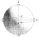
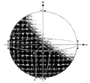
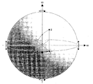
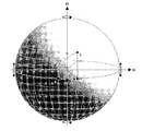
A viewing angle compensation effect of the present invention can be described through a Poincare Sphere. Since the Poincare Sphere is a very useful tool to express the change of the polarization state at a predetermined angle, the Poincare Sphere can express the change of the polarization state when light irradiated at a predetermined viewing angle passes through optical elements in the liquid crystal display displaying the image by using polarization. In the present invention, the predetermined viewing angle is the direction of θ = 60° and Ф = 45° in a hemicircular coordinate system shown in FIG. 4 and the change of the polarization state of light emitted in this direction will be described based on 550nm, a wavelength which humans feel as the brightest. In detail, it shows changes in polarization state on a Poincare Sphere of light coming out in the front direction when the surface of the Ф direction is rotated to the viewer direction by θ about an axis of Ф+90° in the front plane. Right-circular polarization appears when the coordinates of the S3 axis are positive (+) on the Poincare Sphere, in which the right-circular polarization, when a certain polarization horizontal component is Ex and polarization vertical component is Ey, implies that phase delay of light of Ex component with respect to Ey component is larger than 0 and smaller than a half wavelength.
Hereafter, in the above configuration, an effect of implementing the black state at all viewing angles when voltage is not applied is described through examples and comparative examples. Although the present invention can be more easily understood through the following embodiments, the following embodiments are provided only as examples of the present invention and do not limit the protective scope of the present invention claimed by the accompanying claims.
EXAMPLES
Wide viewing angle effects were compared through simulation by using TECH WIZ LCD 1D (Sanayi System Co., Ltd, Korea), which is an LCD simulation system in the following first to sixth examples and the first to sixth comparative examples.
FIRST EXAMPLE
Actually-measured data of each optical film, a liquid crystal cell, and a backlight according to the present invention was used for the TECH WIZ LCD 1D (Sanayi System Co., Ltd, Korea) with a stacked structure shown in FIG. 1(a). The structure of FIG. 1(a) is described in detail hereinafter.
From the backlight unit 40, the second protection film 13, the second polarizer 11, the second compensation film 14, the blue phase liquid crystal cell 30, the first compensation film 24, the first polarizer 21, and the first protection film 23 are disposed, in which the absorption axis 12 of the second polarizer 11 is in the vertical direction when seen from the display side and the absorption axis 22 of the first polarizer 21 is in the horizontal direction. Therefore, the absorption axes 12 and 22 of the first and second polarizers 21 and 11 are perpendicular to each other and the slow axis 25 of the first compensation film 24 and the absorption axis 22 of the first polarizer 21 are parallel to each other.
When the electric field is not applied to the liquid crystal cell, the refractive index of the liquid crystal cell is isotropic and when the electric filed is applied to the liquid crystal cell, the refractive index increases in the electric field applying direction. As a sample product of the liquid crystal mode, a blue phase liquid crystal (Samsung Electronics Co. Ltd., SID 2008) was used. When the liquid crystal is adopted, initial liquid crystal alignment is not required, thereby simplifying a manufacturing process of the liquid crystal cell.
Meanwhile, each optical film and the backlight unit used in the first example have the following optical properties.
First, the first and the
second polarizers 11 and 21 are provided with polarizing function by dyeing an extended PVA with iodine and the polarizing performance of the polarizers having a 99.9% or more luminance degree of polarization and 41% or more luminance group transmittance within a visible light region of 370 to 780nm. The luminance degree of polarization and the luminance group transmittance are defined by the following Formulae 4 to 8, when transmittance of the transmittance axis according to a wavelength is TD(λ), transmittance of the absorption axis according to a wavelength is MD(λ), and luminance compensation value defined in JIS Z 8701:1999 is
, where S(λ) is light source spectrum and the light source is a C-light source.
[Formula 4]
[Formula 5]
[Formula 6]
[Formula 7]
[Formula 8]
There were used the second compensation film 14 of the second coupled polarizing plate having an in-plane retardation (R0) of 2.0nm and a thickness retardation (Rth) of 90nm and the first compensation film 24 of the first coupled polarizing plate having an in-plane retardation (R0) of 140nm and a refractive index ratio (NZ) of -0.11 at a wavelength of 589.3nm.
The wavelength dispersive characteristic of full range of wavelengths for the second compensation film 14 was shown in FIG. 5 and the ratio of in-plane retardation (wavelength of 380nm) / an in-plane retardation (wavelength of 780nm) = [R0 (380nm) / R0 (780nm)] was 0.862. The wavelength dispersive characteristic of full range of wavelengths for the first compensation film 24 was shown in FIG. 6 and the ratio of in-plane retardation (wavelength of 380nm) / an in-plane retardation (wavelength of 780nm) = [R0 (380nm) / R0 (780nm)] was 1.197.
TAC (TriAcetyl Cellulose) film having an optical property of a thickness retardation (Rth) of 50nm with respect to incident light of 589.3nm was used for each of the first and the second protection films 23 and 13 to protect the first and the second polarizers. Actually-measured spectrum data of a backlight equipped in a liquid crystal TV PAVV (LTA460HR0) model of 46 inches (SAMSUNG ELECTRONICS Co. Ltd.) was used for the backlight unit.
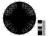
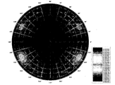
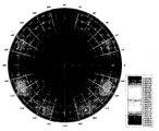
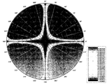
By performing a simulation of transmittance from all light directions after stacking optical components, as shown in FIG. 1(a), the result shown in FIG. 7 is acquired. The change of the polarization state at the wavelength of 550nm at a reference viewing angle (θ = 60° and Ф = 45°)is shown in FIG. 8. A polarization state when passing through the second polarizer 11 on the Poincare Sphere is represented by 1, a polarization state when passing through the second compensation film 14 and a polarization state when passing through the liquid crystal cell are represented by 2, and a polarization state when passing through the first compensation film 24 is represented by 3.
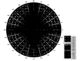
FIG. 7 shows the distribution of transmittance from all light directions when a black state is displayed on the screen, in which the transmittance is 0% to 0.05%, the portion exceeding 0.05% transmittance is shown by red color and low-transmittance portion is shown by blue color when the black state is shown, in the range of the scale. In this case, it can be seen that the wider the blue portion at the center, the easier it is to ensure a wider viewing angle by indicating the wider viewing angle.
Therefore, it is seen that a viewing angle compensation effect is shown, which is better than FIG. 9 showing transmittance from all light directions when a polarizing plate for the in-plane switching liquid crystal display (I Plus Pol configuration, DONGWOO FINE-CHEM, Korea) is applied to the liquid crystal mode of the present invention.
SECOND EXAMPLE
Although it was configured the same as in the first example, the liquid crystal display for the blue phase liquid crystal is manufactured by using the second compensation film 14 having an in-plane retardation (R0) of 2.0nm and a thickness retardation (Rth) of 300nm and the first compensation film 24 having an in-plane retardation (R0) of 55nm and a refractive index ratio (NZ) of -5.9 at a wavelength of 589.3nm.
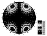
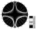
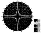
FIG. 10 shows the distribution of transmittance from all light directions when a black state is displayed on the screen, in which the transmittance is 0% to 0.05%, the portion exceeding 0.05% transmittance is shown by red color and low-transmittance portion is shown by blue color when the black state is shown, in the range of the scale. In this case, it can be seen that the wider the blue portion at the center, the easier it is to ensure a wider viewing angle by displaying the viewing angle.
Therefore, it is seen that a viewing angle compensation effect is shown, which is equal to FIG. 9 showing transmittance from all light directions when a polarizing plate for the in-plane switching liquid crystal display (I Plus Pol configuration, DONGWOO FINE-CHEM, Korea) is applied to the liquid crystal mode of the present invention.
FIG. 11 shows an optical compensation principle of the second example on the Poincare Sphere and FIG. 8 shows an optical compensation principle of the first example on the Poincare Sphere. In the figures, it can be seen that innumerable compensable paths are present between two paths on the Poincare Sphere and the optical properties are not improved by only the first and second compensation films 14 and 24 but the optimal optical properties of the first compensation film 24 are determined depending on the optical properties of the second compensation film 14.
THIRD EXAMPLE
Although it was configured the same as in the first example, from the backlight unit 40, the first protection film 23, the first polarizer 21, the first compensation film 24, the blue phase liquid cell 30, the second compensation film 14, the second polarizer 11, and the second protection film 13 are disposed as shown in FIG. 1(b). The absorption axis 22 of the first polarizer 21 is in the vertical direction when seen from the display side and the absorption axis 12 of the second polarizer 11 is in the horizontal direction when seen from the display side. Therefore, the absorption axes 22 and 12 of the first and second polarizers 21 and 11 are perpendicular to each other and the slow axis 25 of the first compensation film 24 and the absorption axis 22 of the first polarizer 21 are parallel to each other.
According to optical properties generated by a difference in internal refractive index in the direction of each film, in a wavelength of 589.3nm, there were used the second compensation film 14 having an in-plane retardation (R0) of 2.0nm and a thickness retardation (Rth) of 90nm and the first compensation film 24 having an in-plane retardation (R0) of 140nm and a refractive index ratio (NZ) of -0.11.
The wavelength dispersive characteristic of full range of wavelengths for the second compensation film 14 was shown in FIG. 5 and the ratio of in-plane retardation (wavelength of 380nm) / an in-plane retardation (wavelength of 780nm) = [R0 (380nm) / R0 (780nm)] was 0.862. The wavelength dispersive characteristic of full range of wavelengths for the first compensation film 24 was shown in FIG. 6 and the ratio of in-plane retardation (wavelength of 380nm) / an in-plane retardation (wavelength of 780nm) = [R0 (380nm) / R0 (780nm)] was 1.197.
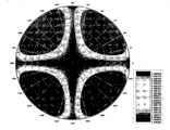
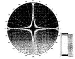
By performing a simulation of transmittance from all light directions after stacking optical components, as shown in FIG. 1(b), the result shown in FIG. 12 is acquired. The change of the polarization state at the wavelength of 550nm at a reference viewing angle (θ = 60° and Ф = 45°)is shown in FIG. 13. A polarization state when passing through the first polarizer 21 on the Poincare Sphere is represented by 1, a polarization state when passing through the first compensation film 24 and a polarization state when passing through the liquid crystal cell are represented by 2, and a polarization state when passing through the second compensation film 14 is represented by 3.
FIG. 12 shows the distribution of transmittance from all light directions when a black state is displayed on the screen, in which the transmittance is 0% to 0.05%, the portion exceeding 0.05% transmittance is shown by red color and low-transmittance portion is shown by blue color when the black state is shown, in the range of the scale. In this case, it can be seen that the wider the blue portion at the center, the easier it is to ensure a wider viewing angle by indicating the wider viewing angle.
Therefore, it is seen that a viewing angle compensation effect is shown, which is better than FIG. 9 showing transmittance from all light directions when a polarizing plate for the in-plane switching liquid crystal display (I Plus Pol configuration, DONGWOO FINE-CHEM, Korea) is applied to the liquid crystal mode of the present invention.
FOURTH EXAMPLE
Although the components of FIG. 1(b) were stacked in the same manner as the third example, the liquid crystal display for the blue phase liquid crystal is manufactured by using the second compensation film 14 having an in-plane retardation (R0) of 2.0nm and a thickness retardation (Rth) of 300nm and the first compensation film 24 having an in-plane retardation (R0) of 55nm and a refractive index ratio (NZ) of -5.9 at a wavelength of 589.3nm.
FIG. 14 shows the distribution of transmittance from all light directions when a black state is displayed on the screen. In this figure, it can be seen that the wide viewing angle can be ensured. FIG. 15 shows a change of a polarization state of a wavelength of 550nm at a reference viewing angle (θ = 60° and Ф = 45°)of the present invention.
FIFTH EXAMPLE
Although it was configured the same as in the first example, the liquid crystal display for the blue phase liquid crystal is manufactured by using the second compensation film 14 having an in-plane retardation (R0) of 2.0nm and a thickness retardation (Rth) of 141nm and the first compensation film 24 having an in-plane retardation (R0) of 99nm and a refractive index ratio (NZ) of -1.0 at a wavelength of 589.3nm.
The transmittance from all light directions of the configuration is shown in FIG. 16. FIG. 17 shows a change of a polarization state of a wavelength of 550nm at a reference viewing angle (θ = 60° and Ф = 45°)of the present invention.
SIXTH EXAMPLE
Although it was configured the same as in the first example, the liquid crystal display for the blue phase liquid crystal is manufactured by using the second compensation film 14 having an in-plane retardation (R0) of 2nm and a thickness retardation (Rth) of 110nm and the first compensation film 24 having an in-plane retardation (R0) of 110nm and a refractive index ratio (NZ) of -0.5 at a wavelength of 589.3nm.
The transmittance from all light directions of the configuration is shown in FIG. 18. FIG. 19 shows a change of a polarization state of a wavelength of 550nm at a reference viewing angle (θ = 60° and Ф = 45°)of the present invention.
FIRST COMPARATIVE EXAMPLE
Although it was configured the same as in the first example, the liquid crystal display for the blue phase liquid crystal is manufactured by using the second compensation film 14 and the first compensation film 24 having optical properties of a general TAC (an in-plane retardation (R0) of 2nm and a thickness retardation (Rth) of 52nm).
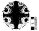
The simulation result of the transmittance from all light directions of the liquid crystal display is shown in FIG. 20. As shown in FIG. 20 below, it can be seen that since the transmittance of an inclined surface is high in the black state, the viewing angle is narrow.
SECOND COMPARATIVE EXAMPLE
Although it was configured the same as in the first example, the liquid crystal display for the blue phase liquid crystal is manufactured by using the first and second compensation films 14 and 24 (an in-plane retardation (R0) of 1nm and a thickness retardation (Rth) of 2nm) having 0-TAC used in a low-price in-plane switching liquid crystal display.
The simulation result of the transmittance from all light directions of the liquid crystal display is shown in FIG. 21. As shown in FIG. 21 below, it can be seen that since the transmittance of an inclined surface is high in the black state, the viewing angle is narrow.
THIRD COMPARATIVE EXAMPLE
Although it was configured the same as in the first example, a blue phase liquid crystal display is manufacturing by arranging the slow axis 25 of the first compensation film 24 and the absorption axis 22 of the first polarizer 21 to be perpendicular to each other.
The simulation result of the transmittance from all light directions of the liquid crystal display is shown in FIG. 22. As shown in FIG. 22 below, it can be seen that since the transmittance of an inclined surface is high in the black state, the viewing angle is narrow.
FOURTH COMPARATIVE EXAMPLE
Although it was configured the same as in the first example, the liquid crystal display for the blue phase liquid crystal is manufactured by using the second compensation film 14 having an in-plane retardation (R0) of 2nm and a thickness retardation (Rth) of 50nm and the first compensation film 24 having an in-plane retardation (R0) of 55nm and a refractive index ratio (NZ) of -2.1 at a wavelength of 589.3nm.
The simulation result of the transmittance from all light directions of the liquid crystal display is shown in FIG. 23. As shown in FIG. 23 below, it can be seen that since the transmittance of an inclined surface is high in the black state, the viewing angle is narrow.
FIFTH COMPARATIVE EXAMPLE
Although it was configured the same as in the first example, the liquid crystal display for the blue phase liquid crystal is manufactured by using the second compensation film 14 having an in-plane retardation (R0) of 2nm and a thickness retardation (Rth) of 50nm and the first compensation film 24 having an in-plane retardation (R0) of 55nm and a refractive index ratio (NZ) of -8 at a wavelength of 589.3nm.
The simulation result of the transmittance from all light directions of the liquid crystal display is shown in FIG. 24. As shown in FIG. 24 below, it can be seen that since the transmittance of an inclined surface is high in the black state, the viewing angle is narrow.
SIXTH COMPARATIVE EXAMPLE
Although it was configured the same as in the first example, the liquid crystal display for the blue phase liquid crystal is manufactured by using the second compensation film 14 having an in-plane retardation (R0) of 2nm and a thickness retardation (Rth) of 350nm and the first compensation film 24 having an in-plane retardation (R0) of 170nm and a refractive index ratio (NZ) of -0.3 at a wavelength of 589.3nm.
The simulation result of the transmittance from all light directions of the liquid crystal display is shown in FIG. 25. As shown in FIG. 25 below, it can be seen that since the transmittance of an inclined surface is high in the black state, the viewing angle is narrow.