WO2010128573A1 - Temperature sensor and temperature sensor system - Google Patents
Temperature sensor and temperature sensor system Download PDFInfo
- Publication number
- WO2010128573A1 WO2010128573A1 PCT/JP2010/001963 JP2010001963W WO2010128573A1 WO 2010128573 A1 WO2010128573 A1 WO 2010128573A1 JP 2010001963 W JP2010001963 W JP 2010001963W WO 2010128573 A1 WO2010128573 A1 WO 2010128573A1
- Authority
- WO
- WIPO (PCT)
- Prior art keywords
- temperature
- lead wire
- temperature sensor
- protective tube
- metal protective
- Prior art date
Links
Images


Classifications
-
- G—PHYSICS
- G01—MEASURING; TESTING
- G01K—MEASURING TEMPERATURE; MEASURING QUANTITY OF HEAT; THERMALLY-SENSITIVE ELEMENTS NOT OTHERWISE PROVIDED FOR
- G01K1/00—Details of thermometers not specially adapted for particular types of thermometer
- G01K1/08—Protective devices, e.g. casings
- G01K1/12—Protective devices, e.g. casings for preventing damage due to heat overloading
-
- G—PHYSICS
- G01—MEASURING; TESTING
- G01K—MEASURING TEMPERATURE; MEASURING QUANTITY OF HEAT; THERMALLY-SENSITIVE ELEMENTS NOT OTHERWISE PROVIDED FOR
- G01K1/00—Details of thermometers not specially adapted for particular types of thermometer
- G01K1/08—Protective devices, e.g. casings
- G01K1/10—Protective devices, e.g. casings for preventing chemical attack
-
- G—PHYSICS
- G01—MEASURING; TESTING
- G01K—MEASURING TEMPERATURE; MEASURING QUANTITY OF HEAT; THERMALLY-SENSITIVE ELEMENTS NOT OTHERWISE PROVIDED FOR
- G01K7/00—Measuring temperature based on the use of electric or magnetic elements directly sensitive to heat ; Power supply therefor, e.g. using thermoelectric elements
- G01K7/16—Measuring temperature based on the use of electric or magnetic elements directly sensitive to heat ; Power supply therefor, e.g. using thermoelectric elements using resistive elements
- G01K7/22—Measuring temperature based on the use of electric or magnetic elements directly sensitive to heat ; Power supply therefor, e.g. using thermoelectric elements using resistive elements the element being a non-linear resistance, e.g. thermistor
- G01K7/24—Measuring temperature based on the use of electric or magnetic elements directly sensitive to heat ; Power supply therefor, e.g. using thermoelectric elements using resistive elements the element being a non-linear resistance, e.g. thermistor in a specially-adapted circuit, e.g. bridge circuit
Definitions
- the present invention relates to a temperature sensor provided with a temperature sensing element whose electric resistance changes with temperature.
- a temperature sensor element used in such a temperature sensor includes a temperature sensor 2 provided with a pair of electrodes 3 and lead wires connected to each of the pair of electrodes 3. 4 and a covering material 5 made of heat-resistant crystalline glass, amorphous glass, or the like that seals the temperature sensing element 2.
- the sensor element When the sensor element is installed in an electric oven (electricity sensor), radiant heater, combustion appliance, exhaust gas purification device, etc., the sensor element is hermetically sealed to protect the sensor element from vibration, external force, combustion gas, etc. It is used in a state of being housed in a high metal protective tube.
- an electric oven electric heater
- combustion appliance combustion appliance
- exhaust gas purification device etc.
- the sensor element is hermetically sealed to protect the sensor element from vibration, external force, combustion gas, etc. It is used in a state of being housed in a high metal protective tube.
- Patent Document 1 when the use environment temperature becomes 750 ° C. or higher, the oxygen partial pressure around the temperature sensing element 2 may fluctuate due to oxidation of the metal protective tube constituting the temperature sensor. It is shown that the temperature-resistance characteristic becomes unstable due to fluctuation of the composition of No. 2. Therefore, Patent Document 1 proposes filling a metal protective tube with an earthquake-resistant filler having a porosity of 30 to 70%.
- Patent Document 1 employs a method in which a fluid seismic filler and a temperature sensor element are simultaneously inserted and embedded in a metal protective tube to heat and cure the seismic filler.
- the air bubbles may remain after curing as the binder volatilizes when the earthquake resistant filler is cured, the presence of the air bubbles cannot be confirmed.
- the seismic filler when inserted into the metal protective tube is powdery, the packing density of the seismic filler in the metal protective tube is not sufficient. Therefore, it cannot be said that the obtained temperature sensor has sufficient reliability with respect to fluctuations in oxygen partial pressure, and the accuracy of the detected temperature is unstable.
- JP 2008-215919 A Japanese Patent No. 3806434
- the present invention has been made based on such a technical problem, and an object of the present invention is to provide a temperature sensor that can stably maintain the accuracy of the detected temperature even in a high temperature environment of 500 ° C. or higher.
- the metal protective tube is made of a stainless alloy or a Ni-base superalloy excellent in high temperature heat resistance.
- constituent metals chromium, nickel, iron, etc.
- platinum, platinum alloy, and nickel constituting the lead wire of the temperature sensor element start to evaporate when the temperature exceeds 500 ° C. These evaporated unstable metals become conductive oxides.
- the temperature sensor element that constitutes the temperature sensor is placed in a closed environment in the metal protective tube, and thus is exposed to an atmosphere environment having a high metal vapor concentration. Since the covering material 5 made of crystalline glass, amorphous glass or the like having high insulation performance is interposed between the lead wires 4, even if the sensor element is energized, as shown in FIG. There is no leakage current between the lead wires 4. In FIG. 12, arrows indicate current. However, as described above, when a conductive material such as chromium oxide adheres so as to fill the space between the lead wires 4, the insulation performance between the lead wires 4 is impaired, and as shown in FIG. Leakage current is generated between the lead wires 4, thereby causing electrolytic corrosion (high temperature migration). As a result, the temperature detected by the temperature sensor becomes inaccurate.
- the temperature sensor of the present invention made there is premised on including a sensor element and a metal protective tube that accommodates the temperature sensing element except for a part of the lead wire.
- the sensor element seals a temperature sensing element whose electrical resistance varies with temperature, a pair of lead wires electrically connected to the temperature sensing element, and a lead wire within a predetermined range from the temperature sensing element and the connection portion. And a covering material to be stopped. Further, in this sensor element, the lead wire is pulled out from the sealing end of the covering material.
- the temperature sensor of the present invention having the above-described configuration is made of a ceramic including a sealed end sealing portion that seals the sealed end, and a lead wire protection portion through which a lead wire drawn out from the sealed end is received and accommodated. And a shield.
- the temperature sensor of the present invention is characterized in that the shield is loosely fitted in the metal protective tube.
- the above temperature sensor is between the temperature sensing element and the metal protective tube, and the sealed end sealing portion seals the sealed end, thereby preventing the conductive material from adhering between the lead wires 4.
- the temperature sensor of the present invention includes a lead wire protection unit.
- the temperature sensor has a temperature gradient in which the front side where the temperature sensing body is present becomes hot during use, and the temperature decreases toward the rear. Therefore, by covering the portion where the material constituting the lead wire is at or above the temperature at which evaporation starts, the lead wire protection portion contributes to prevention of metal evaporation from the lead wire.
- the shield is loosely fitted in the metal protective tube.
- the protective tube is made of metal and the shield is made of ceramic, both have a difference in linear expansion coefficient.
- the linear expansion coefficient of Ni-base superalloy is 11 to 12 ⁇ 10 ⁇ 6 / ° C.
- the linear expansion coefficient of alumina is 7 to 8 ⁇ 10 ⁇ 6 / ° C. Therefore, if a temperature sensor in which a shield is closely accommodated in a metal protective tube is used for a long time, a gap is repeatedly formed between the protective tube and the shield, so that the temperature sensor The initial state cannot be maintained. Therefore, the detected temperature becomes unstable.
- the present invention provides that the shield is loosely fitted in the metal protective tube.
- the temperature sensor of the present invention in which the shield is loosely fitted in the metal protective tube from the beginning, the sensor element and the shield that are integrally formed in advance are inserted and fixed separately in the protective tube that is formed in advance. Therefore, manufacturing is easy.
- the lead wire protection portion is a ceramic filling interposed between the protection portion main body having a through hole through which the lead wire passes and the protection portion main body and the lead wire passing through the through hole. It is preferable to provide a material.
- the lead wire can be fixed in the lead wire protection section. This filler can be composed of a ceramic body formed integrally with the shield.
- the side on which the temperature sensing element is provided is defined as the front (front), and the side on which the lead wire is extended is defined as the rear (rear).
- the resistance value of the temperature sensing element is often about 1000 ⁇ or less, and the temperature coefficient of the resistance value (electric resistance per 1 ° C.
- the energization current must be reduced, and the output voltage per 1 ° C. is inevitably lowered.
- the AD converter If the AD converter is to detect the temperature range from 0 ° C. to 1000 ° C., the AD converter needs to have a resolution of 10 bits or more. A 12-bit or 16-bit AD converter exceeding 10 bits is relatively expensive as a mass-produced product and is not suitable for consumer use.
- the temperature sensor system of the present invention includes any one of the above temperature sensors, an energization circuit that supplies a temperature detection current to the temperature sensor, an AD converter that receives temperature information detected by the temperature sensor as an analog voltage signal,
- the energization circuit is a temperature that supplies a pulsed temperature detection current to the temperature sensor based on an instruction from the controller A sensor system is provided.
- the temperature sensor of the present invention it is possible to prevent high-temperature migration due to adhesion of a conductive substance between lead wires, and to keep the sealed state of the temperature sensing element by the covering material. Therefore, it is possible to stably ensure the detection temperature accuracy of the temperature sensor.
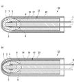
- (A) is a longitudinal sectional view of the temperature sensor of the first embodiment
- (b) is a sectional view taken along the arrow 1b-1b of (a) (excluding the metal protective tube 20)
- (c) is the second embodiment. It is a longitudinal cross-sectional view of this temperature sensor.
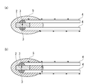
- (A) is a longitudinal cross-sectional view of the temperature sensor of 3rd Embodiment
- (b) is a longitudinal cross-sectional view of the temperature sensor of 4th Embodiment. It is a figure which shows the preparation procedures of the sensor element unit by 1st Embodiment.
- (A) is a longitudinal sectional view of the temperature sensor of the fifth embodiment
- (b) is a sectional view taken along the line A-A ′ of (a).
- Fig.1 (a) shows the temperature sensor 1 of 1st Embodiment of this invention.
- the temperature sensor 1 includes a sensor element unit 10 and a metal protective tube 20 that houses the sensor element unit 10 except for a part on the rear side of the lead wire 4.
- the sensor element unit 10 includes a temperature sensing element 2 whose electrical resistance varies with temperature, a pair of lead wires 4 electrically connected to the temperature sensing element 2 via an electrode 3, and the temperature sensing element 2 and the electrode 3.
- the lead wire 4 is drawn out from the sealing end 6 of the covering material 5.
- the temperature sensing element 2 it is preferable to use a thermistor, but a material whose electric resistance varies with temperature can be widely applied.
- the thermistor includes, for example, Y, Cr, Mn, Ca and O previously disclosed in Patent Document 2 by the present inventor, and Y: Cr: Mn: Ca
- the temperature sensing element 2 composed of this metal oxide can measure the temperature up to a high temperature of 1000 ° C. or higher. However, this is only an example, and it goes without saying that other thermistors can be used.
- platinum or a platinum alloy can be used as the lead wire 4.
- a platinum alloy containing 1 to 20 wt% iridium is preferable from the viewpoint of high temperature durability.
- the covering material 5 is made of amorphous glass or crystallized glass. Each of these can be used alone, or an amorphous glass and a crystallized glass can be mixed and used so as to have a desired thermal expansion coefficient.
- the crystallized glass for example, those composed of silicon oxide, calcium oxide, manganese oxide, and aluminum oxide are preferable. More specifically, SiO 2 : 30 to 60 wt%, CaO: 10 to 30 wt%, MgO: 5 Those having a composition of ⁇ 25 wt% and Al 2 O 3 : 0 to 15 wt% can be used in the present invention. Moreover, you may comprise using what added inorganic material powder to glass.
- Examples of the inorganic material powder added to glass include aluminum oxide (Al 2 O 3 ), magnesium oxide (MgO), yttrium oxide (Y 2 O 3 ), chromium oxide (Cr 2 O 3 ), zirconium oxide (ZrO 2 ), and the like.
- Al 2 O 3 aluminum oxide
- MgO magnesium oxide
- Y 2 O 3 yttrium oxide
- Cr 2 O 3 chromium oxide
- ZrO 2 zirconium oxide
- the sensor element unit 10 includes a sealed end sealing body 7 made of ceramic, and a lead wire protective tube 8 in which a pair of lead wires 4 penetrates and is accommodated behind the sealing end sealing body 7.
- the sealed end sealing body 7 and the lead wire protective tube 8 constitute the shielding body of the present invention.
- the sealed end sealing body 7 provided between the sensor element unit 10 and the metal protective tube 20 has a frustoconical outer shape and surrounds the rear end side of the covering material 5 to seal the sealed end 6. Therefore, the conductive composition does not adhere between the lead wires 4.
- the sealed end sealing body 7 is made of a ceramic such as alumina (Al 2 O 3 ) or silicon nitride (Si 3 N 4 ). A method of forming the sealed end sealing body 7 will be described later.
- the cylindrical lead wire protective tube 8 following the sealed end sealing body 7 is formed with two holding holes 8h that receive and hold a pair of lead wires 4 extending in the axial direction.
- the holding hole 8h can be provided with one hole having a size capable of accommodating the two lead wires 4, but providing the two holding holes 8h so as to correspond to each of the lead wires 4 makes the lead wire 4 predetermined. Preferred for fixing in position.
- a filler 9 made of ceramic is interposed in a gap excluding the lead wire 4.
- the lead wire protection tube 8 preferably has a length that can accommodate a region where the temperature of the lead wire 4 is 500 ° C. or more when the temperature sensor 1 is used.
- the lead wire protective tube 8 and the filler 9 are also made of alumina (Al 2 O 3 ), silicon nitride (Si 3 N 4 ), etc., like the sealed end sealing body 7.
- the temperature sensor 1 is manufactured by inserting and fixing a sensor element unit 10 formed integrally in advance to a separately formed metal protective tube 20. At this time, the shield is loosely fitted in the metal protective tube 20 by providing a gap between the metal protective tube 20 and the portion of the shield composed of the sealed sealing body 7 and the lead wire protective tube 8.
- the tip of the coating material 5 is directly applied to the inner peripheral surface of the metal protective tube 20, and the tip of the coating material 5 and the metal protective tube
- the present invention allows the tip of the covering material 5 to indirectly contact the inner peripheral surface of the metal protective tube 20 by interposing a filler and an adhesive between 20.
- a gap is provided between the portion of the shielding body composed of the sealed end sealing body 7 and the lead wire protection tube 8 and the metal protection tube 20, and is nothing but a loose fit.
- the temperature sensor 1 includes a metal protective tube 20 that accommodates the sensor element unit 10 except for a part on the rear side of the lead wire 4.
- the metal protective tube 20 is made of a stainless alloy, a Ni-base superalloy, or other heat resistant alloy. These alloys contain a large amount of Ni and Cr in order to ensure heat resistance.
- JIS NCF600 which is an example of a Ni-base superalloy, contains about 75 wt% Ni and about 16 wt% Cr.
- the metal protective tube 20 Since the metal protective tube 20 is exposed to an oxidizing atmosphere during use, the metal protective tube 20 is oxidized with use. If the properties of the metal protective tube 20 are changed in this way, a detection temperature error is caused. Further, when the metal protective tube 20 is oxidized, the inside of the metal protective tube 20 is in a reduced state, and O 2 is taken away from the temperature-sensitive body 2 made of oxide, thereby causing a composition shift in the temperature-sensitive body 2. For this reason, the characteristics of the temperature sensing element 2 may change, leading to a detection temperature error. Therefore, it is preferable that the surface of the metal protective tube 20 is previously oxidized.
- the metal protective tube 20 is provided to hold the temperature sensing body 2 and the lead wire 4 and to protect these items from mechanical stress from the outside of the metal protective tube 20.
- the metal protective tube 20 is a pipe-like object, and one end (front end side) that houses the temperature sensing element 2 for measuring temperature is closed (sealed), and the other end (rear end side) is connected to the lead wire 4. Open for withdrawal.
- the drawn lead wire 4 is connected to a flexible electric wire with insulation coating that is covered with polyethylene, Teflon (registered trademark), silicon, vinyl chloride, or the like for connection to a measurement circuit. For this reason, in use, it is necessary that the temperature on the rear end side of the metal protective tube 20 is lowered to a temperature range in which these organic materials can be used. In addition, when the metal protective tube 20 is attached to a high temperature furnace or the like, the lower the temperature of the attachment portion is advantageous in terms of characteristics such as strength, corrosion resistance, and the response of the temperature sensor. Generally, it is provided on the end side.
- the front end side of the metal protective tube 20 is at a high temperature for measuring temperature, and there is a temperature difference (temperature distribution / temperature gradient) between the front end and the rear end of the metal protective tube 20.
- the front end side may be 800 ° C. and the rear end side may be 200 ° C.
- the reason for sealing the tip side of the metal protective tube 20 is to isolate a constant environment in the metal protective tube 20 that houses the temperature sensing element 2 from various atmospheres such as oxidation, reduction, and sulfidation at high temperatures. .
- oxidation and oxidation are performed on both the outer peripheral surface and the inner peripheral surface of the metal protective tube 20 at the tip of the metal protective tube 20 that becomes high temperature.
- Metal emission (evaporation) occurs with reduction.
- the amount of metal evaporation increases compared to the outer peripheral surface.
- the amount of metal evaporation decreases as the temperature approaches the rear end of the metal protective tube 20.
- the amount of chromium deposited is an example. That is, as a matter of fact, a large amount of chromium adheres to the temperature sensing element 2 disposed on the front end side of the metal protective tube 20, and the amount of adhesion decreases as the distance from the rear end of the metal protective tube 20 becomes closer. Since the lead wire 4 drawn out from the temperature sensing element 2 is also governed by the temperature distribution of the metal protective tube 20, the amount of metal evaporation from the lead wire 4 increases in the vicinity of the temperature sensing element 2 on the higher temperature side.
- the metal evaporates from the lead wire 4 When the metal evaporates from the lead wire 4, a gap is formed between the lead wire 4 and the covering material 5, and when the temperature sensing body 2 is energized, it causes high temperature migration. As described above, it is possible to prevent the metal from evaporating and the lead wire 4 from becoming thin, to prevent the metal evaporated from the lead wire 4 from flying to other places, and to the metal flying from the metal protective tube 20. It is preferable that the metal evaporated from the lead wire 4 is not adhered between the lead wires 4. Furthermore, it is preferable to configure the temperature sensor 1 so that the temperature of the lead wire 4 exposed from the lead wire protection tube 8 is 400 ° C. or less, for example, where the metal does not evaporate or is suppressed to a very small amount.
- covering material 5 shall be assembled
- This may be referred to herein as a unit intermediate for convenience.
- the lead wire 4 is inserted into the holding hole 8 h of the lead wire protective tube 8 until the rear end of the covering member 5 of the unit intermediate body and the front end of the lead wire protective tube 8 contact each other.
- the unit intermediate is placed in the mold 11.
- the molding die 11 includes a main die 11a and a head 11b, and an injection port 11c is formed in the head 11b.
- a raw material LM for forming the sealed end sealing body 7 and the filler 9 is injected from a raw material supply source (not shown) into the main mold 11a through the injection port 11c.
- the unit intermediate has a gap between the covering material 5 and the main mold 11a, and the lead wire protective tube 8 is arranged in the mold 11 without a gap between the main mold 11a.
- the raw material LM is press-fitted from the injection port 11c.
- This raw material LM consists of ceramic powder and a dispersion medium, and has fluidity.
- As the dispersion medium alcohol-based and water-based liquid materials that impart fluidity to the raw material LM can be widely applied. Since a gap is provided between the main mold 11a and the maximum outer diameter portion of the covering material 5, the raw material LM passes through the gap and reaches the front end of the lead wire protective tube 8, and the rear end side of the covering material 5 Can surround.
- the raw material LM enters the gap between the lead wire 4 and the holding hole 8h of the lead wire protective tube 8, and the gap is filled with the raw material LM.
- the lead wire protection tube 8 is disposed in the main mold 11 a without a gap, the raw material LM is not supplied around the lead wire protection tube 8.
- the unit intermediate is taken out from the mold 11 as shown in FIG. Excess raw material LM on the outer periphery of the covering material 5 is removed, and the outer shape of the covering material 5 is adjusted. Since the outer shape is adjusted in this way, the sealed end sealing body 7 has a truncated cone shape.
- the excess raw material LM is removed and the rear end side of the covering material 5 is surrounded.
- the covering material 5 is preferably exposed without being covered with the sealed end sealing body 7 on the front end side. Thereafter, the unit intermediate body is heated to a predetermined temperature to sinter the raw material LM to form the sealed end sealing body 7 and the filler 9 (FIG. 3E).
- the raw material LM can be supplied to the portions corresponding to the sealed end sealing body 7 and the filler 9 by one step of injection.
- the sealed end sealing body 7 and the filler 9 are made of an integrated ceramic after sintering, the unit intermediate body and the lead wire protective tube 8 can be firmly joined.
- the lead wire protection tube 8 is made of a previously sintered ceramic, so that the lead wire 4 can be accurately positioned.
- the sintering can be completed in a short time.
- the temperature sensor 30 in FIG. 1C includes a sensor element unit 25 and a metal protective tube 20 that houses the sensor element unit 25 except for a part on the rear side of the lead wire 4.
- the sensor element unit 25 can be regarded as a shield 26 formed by integrally manufacturing the sealed end sealing body 7 and the lead wire protection tube 8 of the first embodiment.
- the shield 26 can be formed by supplying a raw material LM made of ceramic powder and a dispersion medium to a predetermined region in a mold to produce a molded body, and then sintering the molded body.
- the shield 26 surrounds the rear end side of the covering material 5 to seal the sealing end 6 and protect the lead wire 4.
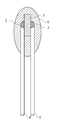
- the temperature sensor 40 in FIG. 2A includes a sensor element unit 35 and a metal protective tube 20 that houses the sensor element unit 35.
- the sensor element unit 35 is provided with a ceramic cladding tube 37 that covers the same shield 36 as the shield 26 of the second embodiment.
- the shield 36 and further the covering tube 37 surround the rear end side of the covering material 5 to seal the sealing end 6 and protect the lead wire 4.
- the temperature sensor 50 in FIG. 2B includes a sensor element unit 45 and a metal protective tube 20 that houses the sensor element unit 45.
- the sensor element unit 45 is provided with a shield 38 that covers the tip of the covering material 5, and further provided with a ceramic cladding tube 39 that accommodates the shield 38.
- the shield 38 and the cladding tube 39 surround the rear end side of the covering material 5 to seal the sealing end 6 and protect the lead wire 4.
- the lead wire 4 includes a first lead wire 41 made of Pt or Pt alloy and a second lead wire 42 made of Ni or Ni alloy.
- the first lead wire 41 is directly connected to the temperature sensing element 2, and the second lead wire 42 is connected to the first lead wire 41 at the connection portion 43.
- a first lead wire 41 made of Pt or a Pt alloy is arranged on the side exposed to a higher temperature, and a second lead wire 42 made of Ni or an Ni alloy is arranged on the rear end side.
- the second lead wire 42 is provided with an insulating coating 44 on the rear end side exposed from the lead wire protective tube 8. Further, most of the portion provided with the insulating coating 44 is covered with a mesh braided tube 45 made of glass fiber or ceramic fiber.
- the lead wire 4 can be fixed to the metal protective tube 20 together with the braided braided tube 45 by providing the caulking portion 21 in a part of the metal protective tube 20.
- the temperature of the lead-out portion of the lead wire 4 from the lead wire protection tube 8 is Lt (° C.), and the temperature at which the metal protection tube 20 and the lead wire 4 start to evaporate by heating is Vt (° C.). Then, it is preferable that Lt and Vt are configured in a relationship of Vt> Lt. Moreover, it is preferable that the connection part 43 of the first lead wire 41 and the second lead wire 42 is provided at a position where the temperature is 600 ° C. or lower during temperature detection.
- the temperature sensor 60 is attached to the housing 70 by the attachment flange 22 and performs temperature detection. And it is necessary to expose the front-end
- FIG. The attachment of the temperature sensor 60 to the housing 70 is necessary to isolate the high temperature part from the normal temperature part outside thereof to prevent human harm and to increase the temperature of the high temperature part efficiently. Therefore, the housing 70 is often at a temperature in the middle region between high temperature and normal temperature.
- the metal protective tube 20 of the temperature sensor 60 has the highest temperature at the tip end portion where the temperature sensing body 2 is housed, and the open end of the metal protective tube 20 from which the lead wire 4 is drawn out. The temperature is the lowest.
- the temperature distribution is 1000 to 400 ° C. in FIG.
- a heat pulling phenomenon occurs in which the heat of the high temperature portion is transmitted through the metal protective tube 20 to the normal temperature portion. It is necessary to reduce the detection temperature error by increasing the length of the metal protective tube 20 as the heat sink is larger.
- the lead wire 4 is extended to a lower portion and is connected to an insulating-coated lead wire 4.
- a press-drawn product has a production limit of an inner diameter of 10 times to 20 times the length.
- the metal protective tube 20 has an inner diameter of ⁇ 3, it can only be manufactured by press drawing to a total length of 30 mm to 60 mm.
- the metal protective tube 20 is divided into two parts, a front end and a rear end, and integrated during the manufacturing process, or a seam or seamless pipe is cut to a required length and one end is sealed. Thus, the length of the metal protective tube 20 is secured. This embodiment is also considered here.
- the temperature sensor 60 can be configured even with the metal protection tube 20 having a short overall length. That is, the metal protective tube 20 by the press drawing process described above can be used.
- the lead wire 4 Since the entire length of the metal protective tube 20 can be shortened, the long lead wire used when manufacturing the temperature sensing element 2 can be used as it is. If the lead wire 4 is not present when the temperature sensing body 20 is manufactured, the temperature detection error cannot be inspected. Especially when the temperature is high, the lead wire 4 is essential. In addition, the temperature sensing body 2 can be held by the lead wire 4 and various processes (coating or dipping) can be performed on the temperature sensing body 2. Since the lead wire 4 is connected to the pair of electrodes 3 of the temperature sensing element 2, it can be used as a signal line. Furthermore, the lead wire protective tube 8 can also be used for ceramic extrusion molding or press-molded product due to the short length of the metal protective tube 20.
- the manufacturing limit of ceramic extrusion molding or press-molded product is equal to or less than the processing limit of the metal protective tube 20.
- the metal protective tube 20 is long, it is necessary to add the lead wire 4 and add several lead wire protective tubes 8 to ensure insulation between the wires, or to fill the metal protective tube 8 with inorganic powder. There is. This is troublesome and becomes a factor that hinders mass production.
- FIGS. 5 (a) and 5 (b) the temperature sensor is held in the housing 70, and the high-temperature energization test is performed with the tip temperature Tmax being 500 to 800 ° C. I did it.
- 5 (a) uses the temperature sensor 1 according to the first embodiment
- FIG. 5 (b) shows a comparative temperature sensor similar to the temperature sensor 1 according to the first embodiment except that the sealed end sealing body 7 is not provided. Was used.
- the results are shown in FIG.
- FIG. 6 when the temperature sensor 1 according to the first embodiment is used, the change in the detected temperature is very small even after an energization current of 10 mA and 1000 hours have elapsed.
- the comparative temperature sensor had an abnormality that the detected temperature greatly deviated in about 10 hours (Tmax: 800 ° C.) even with an energization current of 0.1 mA (Comparative-1).
- the energizing current becomes 10 mA (Comparison-2)
- the detected temperature abnormality further occurs in a short time.
- the larger the energizing current the shorter the durability time of the temperature sensor.
- the temperature sensor according to the present invention has improved high-temperature energization durability, so that a large detection voltage can be extracted by energizing a high current in a short pulse form within a range where the temperature sensor does not self-heat. Therefore, when the temperature sensor according to the present invention is used, the energization circuit C1 is used which connects the resistor R in series with the temperature sensing element 2 shown in FIG. 7A and inputs the divided voltage to the amplifier A as the detection voltage. The detected current can be input to the AD converter CV shown in FIG. That is, the temperature sensor system shown in FIG.
- the 7B includes a temperature sensor (temperature sensor) 2, an energization circuit C ⁇ b> 2 that supplies a temperature detection current to the temperature sensor 2, and temperature information detected by the temperature sensor 2. Is input as an analog voltage signal, and a controller CTR that performs a control operation by converting a digital signal converted by the AD converter CV into a temperature.
- the energization circuit C2 includes two energization circuits of a first energization circuit C21 and a second energization circuit C22 that are connected in parallel between the reference power supply BPS and the temperature sensing element 2.
- the first energization circuit C21 includes a transistor Tr1 whose collector CL1 is connected to the reference power supply BPS, and a resistor R1 connected in series to the transistor Tr1 via the emitter E1.
- the second energizing circuit C22 includes a transistor Tr2 whose collector CL2 is connected to the reference power supply BPS, and a resistor R2 connected to the transistor Tr2 via the emitter E2.
- the resistance values of the resistors R1 and R2 are different.
- the transistor Tr1 is connected to the controller CTR via the base B1, and the transistor Tr2 is connected to the controller CTR via the base B2.
- the controller CTR controls the ON / OFF operation of the transistor Tr1 and the transistor Tr2 by supplying a base current to the base B1 or the base B2.
- a temperature detection current is supplied to the temperature sensing element 2 via the first energization circuit C21.
- the divided voltage of the resistor R1 and the temperature sensing element 2 becomes temperature information (analog voltage).
- Signal is input to the AD converter CV.
- the digital signal converted by the AD converter CV is input to the controller CTR, and the controller CTR converts this digital signal into a detected temperature.
- the controller CTR can control the operation of the equipment and device provided with the temperature sensor system based on the obtained detected temperature.
- a temperature detection current is supplied to the temperature sensing element 2 via the second energization circuit C22.
- the divided voltage of the resistor R2 and the temperature sensing element 2 becomes temperature information (analog voltage).
- Signal is input to the AD converter CV.
- the detected temperature is obtained in the same manner as described above, and the controller CTR performs various controls based on the obtained detected temperature.
- one of the first energization circuit C21 and the second energization circuit C22 selectively supplies a temperature detection current to the temperature sensing element 2 based on an instruction from the controller CTR, but this selection is detected. Determined by temperature. For example, as shown in FIG. 7C, when the detected temperature is low, the first energizing circuit C21 is turned on and the second energizing circuit C22 is turned off. When the detected temperature is high, the first energizing circuit C21 is turned off. Then, the second energization circuit C22 is turned ON.
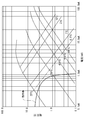
- FIG. 8 shows IV (current-voltage) characteristics of the thermistor according to this embodiment in still air at 25 ° C., 200 ° C., 400 ° C., 600 ° C., and 800 ° C.
- This IV characteristic is obtained by plotting the terminal voltage of the thermistor when a constant current is passed through the thermistor in a logarithmic graph in which the vertical axis represents the voltage value and the horizontal axis represents the current value.
- the voltage value increases to 45 ° diagonally to the right in accordance with the current value for applying a constant current to the thermistor.
- the voltage value starts increasing, and when it passes the voltage maximum point, the voltage value starts decreasing.
- the thermistor exhibits such IV characteristics.
- the thermistor according to the present embodiment displays the power consumption increasing from the ambient temperature by 0.5 ° C., 1 ° C., 5 ° C., and 10 ° C. according to the power consumption.
- a plot of is shown.
- an increase of 0.5 ° C. means that the thermistor temperature is 25.5 ° C. even though the ambient temperature is 25 ° C., and that a temperature higher by 0.5 ° C. than the ambient temperature 25 ° C. is detected Become.
- the thermistor heat dissipation constant (W / ° C.) generally referred to is when the thermistor self-heats by 1 ° C. due to Joule heat. Since it is a constant, the self-heating temperature will increase 45 degrees diagonally to the left. For this reason, the result shown in FIG. 8 is often obtained.
- a thermistor having such an IV characteristic alone is connected to the energization circuit C1 shown in FIG. 7A, and the voltage value input to the amplifier A and the current value flowing through the thermistor are expressed as I
- the operating line of the thermistor plotted on the ⁇ V characteristic diagram is shown.
- the resistance value of the series resistor R that limits the current supplied to the thermistor (temperature sensor) 2 is appropriately selected so that the amount of self-heating generated by the IV characteristics of the thermistor 2 is less than the allowable error.
- the self-heating temperature becomes maximum at an ambient temperature of 25 ° C. to 200 ° C., and it is shown in FIG. 8 that the value is 0.5 ° C.
- the intersection of the IV characteristic and the operating line indicates the voltage value input to the amplifier A when the temperature is measured by the energizing circuit C1 shown in FIG. For example, if the ambient temperature is 25 ° C, the voltage value is 3.8V, and if it is 200 ° C, it is 0.8V.
- FIG. 9 shows the pulse IV characteristics of the same thermistor shown in FIG. 8 in still air at 25 ° C., 200 ° C., 400 ° C., 600 ° C., and 800 ° C.
- This pulse IV characteristic is generated in a pulse shape according to the energization period when a pulse constant current having a determined energization period composed of a period in which the thermistor is energized (ON) and a period in which the thermistor is not energized (OFF) is energized.
- the thermistor terminal voltage is plotted on a log-log graph with the vertical axis representing the pulse voltage value and the horizontal axis representing the pulse current value.
- the thermistor Since the thermistor self-heats little by little even during the ON period, if the energization time is long, it will generate a large amount of self-heat. Therefore, the thermistor is cooled by providing a period for turning off the energization by energizing the pulse.
- the voltage value increases to 45 ° diagonally to the right depending on the current value for applying a constant pulse current to the thermistor, and when self-heating gradually begins due to Joule heat, the pulse voltage value increases. In the same way, even if pulse energization occurs, the pulse voltage value starts to decrease when passing through the voltage maximum point.
- the thermistor displays the power consumption that rises by 0.5 ° C., 1 ° C., 2 ° C., 3 ° C. from the ambient temperature in accordance with the power consumption by the pulse energization.
- a rising plot is shown.
- FIG. 8 and FIG. 9 are compared, the temperature rise is smaller when the current is applied by the pulse even with the same power consumption. Therefore, the voltage maximum point is much larger in the pulse IV characteristic than in the IV characteristic due to continuous energization.
- FIG. 9 when a thermistor having such a pulse IV characteristic alone is connected to the energizing circuit C2 shown in FIG. 7B, the voltage value input to the AD converter CV and the thermistor 2 flow.
- the operating line of the thermistor 2 in which the current value is plotted on the IV characteristic diagram is shown.
- the transistors Tr1 and Tr2 in the two energization circuits including the first energization circuit C21 and the second energization circuit C22 are switched by a signal from the controller CTR.
- the second energization circuit C22 measures the high temperature side, and the resistance value of the current limiting resistor R2 is appropriately selected so that the self-heating value indicated by the pulse IV characteristic of the thermistor 2 is less than the allowable error. .
- the self-heating temperature becomes maximum at an ambient temperature of 400 ° C., and FIG. 9 shows that the value is 1 ° C. or less.
- the first energizing circuit C21 measures the low temperature side, and the resistance value of the current limiting resistor R1 is the same as the limiting resistor R of the energizing circuit C1 shown in FIG.
- FIG. 7C shows the timing when the thermistor 2 is energized by switching the transistors Tr1 and Tr2 in the energization circuit shown in FIG. 7B.
- the time during which the low-temperature side transistor Tr1 is OFF and the high-temperature side transistor Tr2 is ON is the same as the energization cycle of the pulse constant current used in the pulse IV measurement with the thermistor 2 alone.
- the time during which the high-temperature transistor Tr2 is OFF and the low-temperature transistor Tr1 is ON is substantially the same as that shown in FIG.
- FIG. 7 (c) shows an example in which pulse energization is performed.
- the energization circuit C2 Since the energization circuit C2 has two circuits, the first energization circuit C21 and the second energization circuit C22, two operation lines are shown in FIG. 9, and there is an intersection of each operation line and the pulse IV characteristic. To do.
- two voltage signals on the high temperature side and the low temperature side are input to the AD converter CV once in one cycle and transmitted as digital signals to the controller CTR. If the low temperature side voltage is less than 0.1 V, the controller CTR determines that the current temperature is 600 ° C. or higher, calculates the next high temperature side voltage value, and calculates the current temperature.
- the controller CTR determines that the current temperature is less than 600 ° C., calculates the low-temperature side voltage value, and calculates the current temperature.
- the first energization circuit C21 and the second energization circuit C22 and two sets of energization circuits are provided so as to correspond to the low temperature region and the high temperature region, but the measurement temperature region is, for example, the low temperature region, the medium temperature region, and the high temperature region.
- three sets of energization circuits are provided. That is, it is sufficient that at least two energization circuits of the present invention are provided, and it is allowed to provide three or more energization circuits.
- the energization circuit C1 in FIG. 7A can be applied by reducing the applied voltage 5V to, for example, 0.5V to suppress the amount of self-heating and combining a high-precision amplifier A. It is essential. On the other hand, if only the measurement in the high temperature region is pulse energization and measurement can be performed while suppressing self-heating, a highly accurate amplifier is not necessary.
- the temperature sensor according to the present invention can be used for various applications. As an example, it can be used for temperature control of an electric heater as shown in FIG. 10A, and can be used for temperature control of a flame burner as shown in FIG. 10B. In any case, the detected temperature from the temperature sensor S and the set temperature are compared in a control circuit including an energization circuit. Based on the comparison result, the electric power is controlled in the case of an electric heater, and the flame burner is controlled. In some cases, the fuel and air to be input are controlled. Specific examples of the electric heater include an oven, a radiant heater, a filter regeneration heater of an exhaust gas purification device (DPF: Diesel particulate filter), and the like. As the flame burner, a gas burner and an oil burner are listed. However, this is only an example and does not limit the present invention.
- DPF Diesel particulate filter
- thermocouples are used to control the temperature, but because thermocouples have a low output voltage, amplifiers of several hundred to several thousand times are essential. The precision one is required. Also, temperature compensation is necessary to increase the detection temperature accuracy. Furthermore, it takes a lot of time to manufacture the thermocouple, and the thermocouple is virtually incapable of managing the contact position of the tip of the sensor, so the accuracy of the temperature measurement position is significantly inferior to the temperature sensor using a thermistor. . For this reason, when a thermocouple is used for a temperature sensor, there is a possibility that the accuracy as a temperature detection product born from the individual difference of the control device as a result of individual differences in the detected temperature, whereas the temperature sensor of the present invention These problems do not occur.
- thermosensor of the present invention it is also possible to detect and control the temperature using a coating material 5, that is, a sensor element in which the temperature sensing element 2 is not coated with glass, but the durability at high temperature energization is remarkably inferior, and it cannot be used at high temperatures.
- a coating material 5 that is, a sensor element in which the temperature sensing element 2 is not coated with glass
- the durability at high temperature energization is remarkably inferior, and it cannot be used at high temperatures.
- an expensive amplifier is required because a signal cannot be taken out, there is an advantage that there is little individual difference, excellent durability, and low cost.
Landscapes
- Physics & Mathematics (AREA)
- General Physics & Mathematics (AREA)
- Nonlinear Science (AREA)
- Measuring Temperature Or Quantity Of Heat (AREA)
Abstract
Provided is a temperature sensor capable of stably maintaining the accuracy of detected temperatures. The aforementioned sensor is equipped with a temperature sensing element (2) whose electrical resistance changes depending on temperature, a pair of lead wires (4) electrically connected to the temperature sensing element (2), and a covering material (5) which seals the temperature sensing element (2) and those portions of the lead wires (4) which are within a specified range. The aforementioned sensor is also equipped with a covering body comprising a sensor element (1) wherein the lead wires (4) are led out of the sealed ends (6) of the covering material (5), a metallic protection tube (20) which accommodates a sensor element (1) except for part of the lead wires (4), a sealed end closing ceramic element (7) which encloses the sealed ends (6), and a lead wire protection tube (8). The covering body is loosely fitted inside the metallic protection tube (20).
Description
本発明は、温度によって電気抵抗が変化する感温体を備えた温度センサに関する。
The present invention relates to a temperature sensor provided with a temperature sensing element whose electric resistance changes with temperature.
自動車の排気ガス、給湯器、ボイラー、オーブンレンジ、ストーブ等の温度を測定するために、温度によって抵抗値が変化する感温体を用いた温度センサが広く利用されている。かかる温度センサに用いられる温度センサ素子(以下、単にセンサ素子)は、図11に示すように、一対の電極3を設けた感温体2と、一対の電極3の各々に接続されたリード線4と、感温体2を封止する耐熱性の結晶質ガラス、非晶質ガラス等からなる被覆材5と、から構成されている。センサ素子を電気オーブン(電気度センサ)、ラジアントヒータ、燃焼器具、排気ガス浄化装置などに設置する場合には、振動・外力・燃焼ガス等からセンサ素子を保護するために、センサ素子は密閉性の高い金属保護管に収納された状態で用いられている。
In order to measure the temperature of automobile exhaust gases, water heaters, boilers, microwave ovens, stoves, etc., temperature sensors using temperature sensing elements whose resistance values change with temperature are widely used. As shown in FIG. 11, a temperature sensor element (hereinafter simply referred to as a sensor element) used in such a temperature sensor includes a temperature sensor 2 provided with a pair of electrodes 3 and lead wires connected to each of the pair of electrodes 3. 4 and a covering material 5 made of heat-resistant crystalline glass, amorphous glass, or the like that seals the temperature sensing element 2. When the sensor element is installed in an electric oven (electricity sensor), radiant heater, combustion appliance, exhaust gas purification device, etc., the sensor element is hermetically sealed to protect the sensor element from vibration, external force, combustion gas, etc. It is used in a state of being housed in a high metal protective tube.
特許文献1には、使用環境温度が750℃以上になると温度センサを構成する金属保護管の酸化により、感温体2の周囲の酸素分圧が変動することがあり、これに伴い感温体2の組成が変動して温度-抵抗値特性が不安定になることが示されている。そこで特許文献1は、金属保護管内に気孔率が30~70%の耐震フィラーを充填することを提案している。
According to Patent Document 1, when the use environment temperature becomes 750 ° C. or higher, the oxygen partial pressure around the temperature sensing element 2 may fluctuate due to oxidation of the metal protective tube constituting the temperature sensor. It is shown that the temperature-resistance characteristic becomes unstable due to fluctuation of the composition of No. 2. Therefore, Patent Document 1 proposes filling a metal protective tube with an earthquake-resistant filler having a porosity of 30 to 70%.
特許文献1は、金属保護管内に流動性の耐震フィラーと温度センサ素子を同時に挿入・埋設し耐震フィラーを加熱硬化させる方法を採用している。耐震フィラーの硬化時にバインダーが揮発するのに伴って気泡が硬化後に残留するおそれがあるものの、気泡の存在を確認することができない。また、金属保護管内に挿入する際の耐震フィラーは粉状のため、金属保護管内における耐震フィラーの充填密度が十分でない。したがって、得られる温度センサは酸素分圧の変動に対して十分な信頼性があるとは言えず、検知温度の精度が不安定である。
Patent Document 1 employs a method in which a fluid seismic filler and a temperature sensor element are simultaneously inserted and embedded in a metal protective tube to heat and cure the seismic filler. Although the air bubbles may remain after curing as the binder volatilizes when the earthquake resistant filler is cured, the presence of the air bubbles cannot be confirmed. Moreover, since the seismic filler when inserted into the metal protective tube is powdery, the packing density of the seismic filler in the metal protective tube is not sufficient. Therefore, it cannot be said that the obtained temperature sensor has sufficient reliability with respect to fluctuations in oxygen partial pressure, and the accuracy of the detected temperature is unstable.
本発明は、このような技術的課題に基づいてなされたもので、500℃以上の高温環境下においても検知温度の精度を安定して保つことができる温度センサを提供することを目的とする。
The present invention has been made based on such a technical problem, and an object of the present invention is to provide a temperature sensor that can stably maintain the accuracy of the detected temperature even in a high temperature environment of 500 ° C. or higher.
温度センサが使用される環境が500℃~1000℃という高温の場合、温度センサ素子を保護する金属保護管の酸化劣化は著しくなる。金属保護管は高温耐熱性に優れた、ステンレス合金、Ni基超合金により作製される。これらの耐熱合金は、構成する金属(クロム・ニッケル・鉄など)が酸化劣化過程において蒸発・放出される。また、温度センサ素子のリード線を構成する白金や白金合金、ニッケルも500℃を越えると蒸発し始めることが一般に知られている。これらの蒸発した不安定な金属は、導電性を有する酸化物となる。
500℃以上の温度を測定する場合、温度センサを構成する温度センサ素子は、金属保護管内の閉塞された環境に置かれるため、金属蒸気濃度の高い雰囲気環境に晒されてしまうことになる。
リード線4間には、高い絶縁性能を有する結晶質ガラス、非晶質ガラス等からなる被覆材5が介在しているので、センサ素子に通電したとしても図12(a)に示すように、リード線4間にリーク電流は生じない。なお、図12において矢印が電流を示す。ところが、上述のとおり、導電性を有する物質、例えば酸化クロムがリード線4間を埋めるように付着すると、リード線4間の絶縁性能が損なわれ、図12(b)に示すように、通電によりリード線4間にリーク電流が生じ、そのために電解腐食(高温マイグレーション)が生じる。その結果、温度センサによる検知温度が不正確になる。 When the environment in which the temperature sensor is used is as high as 500 ° C. to 1000 ° C., the oxidative deterioration of the metal protective tube that protects the temperature sensor element becomes significant. The metal protective tube is made of a stainless alloy or a Ni-base superalloy excellent in high temperature heat resistance. In these heat-resistant alloys, constituent metals (chromium, nickel, iron, etc.) are evaporated and released during the oxidative deterioration process. Further, it is generally known that platinum, platinum alloy, and nickel constituting the lead wire of the temperature sensor element start to evaporate when the temperature exceeds 500 ° C. These evaporated unstable metals become conductive oxides.
When measuring a temperature of 500 ° C. or higher, the temperature sensor element that constitutes the temperature sensor is placed in a closed environment in the metal protective tube, and thus is exposed to an atmosphere environment having a high metal vapor concentration.
Since the coveringmaterial 5 made of crystalline glass, amorphous glass or the like having high insulation performance is interposed between the lead wires 4, even if the sensor element is energized, as shown in FIG. There is no leakage current between the lead wires 4. In FIG. 12, arrows indicate current. However, as described above, when a conductive material such as chromium oxide adheres so as to fill the space between the lead wires 4, the insulation performance between the lead wires 4 is impaired, and as shown in FIG. Leakage current is generated between the lead wires 4, thereby causing electrolytic corrosion (high temperature migration). As a result, the temperature detected by the temperature sensor becomes inaccurate.
500℃以上の温度を測定する場合、温度センサを構成する温度センサ素子は、金属保護管内の閉塞された環境に置かれるため、金属蒸気濃度の高い雰囲気環境に晒されてしまうことになる。
リード線4間には、高い絶縁性能を有する結晶質ガラス、非晶質ガラス等からなる被覆材5が介在しているので、センサ素子に通電したとしても図12(a)に示すように、リード線4間にリーク電流は生じない。なお、図12において矢印が電流を示す。ところが、上述のとおり、導電性を有する物質、例えば酸化クロムがリード線4間を埋めるように付着すると、リード線4間の絶縁性能が損なわれ、図12(b)に示すように、通電によりリード線4間にリーク電流が生じ、そのために電解腐食(高温マイグレーション)が生じる。その結果、温度センサによる検知温度が不正確になる。 When the environment in which the temperature sensor is used is as high as 500 ° C. to 1000 ° C., the oxidative deterioration of the metal protective tube that protects the temperature sensor element becomes significant. The metal protective tube is made of a stainless alloy or a Ni-base superalloy excellent in high temperature heat resistance. In these heat-resistant alloys, constituent metals (chromium, nickel, iron, etc.) are evaporated and released during the oxidative deterioration process. Further, it is generally known that platinum, platinum alloy, and nickel constituting the lead wire of the temperature sensor element start to evaporate when the temperature exceeds 500 ° C. These evaporated unstable metals become conductive oxides.
When measuring a temperature of 500 ° C. or higher, the temperature sensor element that constitutes the temperature sensor is placed in a closed environment in the metal protective tube, and thus is exposed to an atmosphere environment having a high metal vapor concentration.
Since the covering
以上の通りであり、金属保護管、リード線4からの金属の蒸発・放出が、高温マイグレーションの発生の原因である。そこでなされた本発明の温度センサは、センサ素子と、リード線の一部を除いて感温体を収容する金属保護管とを備えることを前提とする。そして、センサ素子は、温度によって電気抵抗が変化する感温体と、感温体に電気的に接続される一対のリード線と、感温体と接続部から所定範囲内のリード線とを封止する被覆材とを有している。また、このセンサ素子は、リード線が被覆材の封止端から引出される。
以上の構成を有する本発明の温度センサは、封止端を密閉する封止端密閉部と、封止端から引き出されるリード線が貫通して収容されるリード線保護部とからなるセラミック製の遮蔽体とを備えることを特徴とする。また本発明の温度センサは、遮蔽体が金属保護管内に遊嵌されていることを特徴とする。 As described above, evaporation / release of metal from the metal protective tube and thelead wire 4 is a cause of occurrence of high temperature migration. The temperature sensor of the present invention made there is premised on including a sensor element and a metal protective tube that accommodates the temperature sensing element except for a part of the lead wire. The sensor element seals a temperature sensing element whose electrical resistance varies with temperature, a pair of lead wires electrically connected to the temperature sensing element, and a lead wire within a predetermined range from the temperature sensing element and the connection portion. And a covering material to be stopped. Further, in this sensor element, the lead wire is pulled out from the sealing end of the covering material.
The temperature sensor of the present invention having the above-described configuration is made of a ceramic including a sealed end sealing portion that seals the sealed end, and a lead wire protection portion through which a lead wire drawn out from the sealed end is received and accommodated. And a shield. The temperature sensor of the present invention is characterized in that the shield is loosely fitted in the metal protective tube.
以上の構成を有する本発明の温度センサは、封止端を密閉する封止端密閉部と、封止端から引き出されるリード線が貫通して収容されるリード線保護部とからなるセラミック製の遮蔽体とを備えることを特徴とする。また本発明の温度センサは、遮蔽体が金属保護管内に遊嵌されていることを特徴とする。 As described above, evaporation / release of metal from the metal protective tube and the
The temperature sensor of the present invention having the above-described configuration is made of a ceramic including a sealed end sealing portion that seals the sealed end, and a lead wire protection portion through which a lead wire drawn out from the sealed end is received and accommodated. And a shield. The temperature sensor of the present invention is characterized in that the shield is loosely fitted in the metal protective tube.
上記の温度センサは、感温体と金属保護管の間にあって封止端密閉部が封止端を密閉することにより、導電性を有する物質がリード線4間に付着することを防止する。
また、本発明の温度センサは、リード線保護部を備える。温度センサは、使用時に感温体が存在する前方側が高温になり、それよりも後方に向けて温度が低くなる温度勾配を有する。そこで、リード線を構成する材料が蒸発を開始する温度以上となる部分を、リード線保護部で覆うことにより、リード線からの金属の蒸発防止に寄与する。 The above temperature sensor is between the temperature sensing element and the metal protective tube, and the sealed end sealing portion seals the sealed end, thereby preventing the conductive material from adhering between thelead wires 4.
The temperature sensor of the present invention includes a lead wire protection unit. The temperature sensor has a temperature gradient in which the front side where the temperature sensing body is present becomes hot during use, and the temperature decreases toward the rear. Therefore, by covering the portion where the material constituting the lead wire is at or above the temperature at which evaporation starts, the lead wire protection portion contributes to prevention of metal evaporation from the lead wire.
また、本発明の温度センサは、リード線保護部を備える。温度センサは、使用時に感温体が存在する前方側が高温になり、それよりも後方に向けて温度が低くなる温度勾配を有する。そこで、リード線を構成する材料が蒸発を開始する温度以上となる部分を、リード線保護部で覆うことにより、リード線からの金属の蒸発防止に寄与する。 The above temperature sensor is between the temperature sensing element and the metal protective tube, and the sealed end sealing portion seals the sealed end, thereby preventing the conductive material from adhering between the
The temperature sensor of the present invention includes a lead wire protection unit. The temperature sensor has a temperature gradient in which the front side where the temperature sensing body is present becomes hot during use, and the temperature decreases toward the rear. Therefore, by covering the portion where the material constituting the lead wire is at or above the temperature at which evaporation starts, the lead wire protection portion contributes to prevention of metal evaporation from the lead wire.
さらに本発明は、遮蔽体が金属保護管内に遊嵌される。保護管は金属で構成され、遮蔽体はセラミックから構成されるので、両者には線膨張係数に差がある。例えば、Ni基超合金の線膨張係数は11~12×10-6/℃であり、アルミナの線膨張係数は7~8×10-6/℃である。そのために、金属保護管内に遮蔽体が密着して収容されている温度センサを長期間使用していると、保護管と遮蔽体との間に隙間が繰り返して形成されることにより、温度センサが初期状態を維持できなくなる。したがって、検知温度が不安定となる。これに対して、例えば金属保護管と遮蔽体の間に当初より隙間を設けておけば、線膨張係数の差異に基づく上記弊害を避けることができる。この効果は、金属保護管と遮蔽体の間の全域に明確な隙間を設けなくても享受できる。例えば、金属保護管と遮蔽体が一部分で接していたとしても、金属保護管と遮蔽体の間に遊びがあるように嵌め合いが緩くなされていれば、線膨張係数の差異に基づく上記弊害を避けることができる。そこで本発明は、遮蔽体が金属保護管内に遊嵌されることを規定する。
Furthermore, according to the present invention, the shield is loosely fitted in the metal protective tube. Since the protective tube is made of metal and the shield is made of ceramic, both have a difference in linear expansion coefficient. For example, the linear expansion coefficient of Ni-base superalloy is 11 to 12 × 10 −6 / ° C., and the linear expansion coefficient of alumina is 7 to 8 × 10 −6 / ° C. Therefore, if a temperature sensor in which a shield is closely accommodated in a metal protective tube is used for a long time, a gap is repeatedly formed between the protective tube and the shield, so that the temperature sensor The initial state cannot be maintained. Therefore, the detected temperature becomes unstable. On the other hand, for example, if a gap is provided from the beginning between the metal protective tube and the shield, the above-described adverse effects based on the difference in linear expansion coefficient can be avoided. This effect can be enjoyed without providing a clear gap across the entire area between the metal protective tube and the shield. For example, even if the metal protective tube and the shield are in contact with each other, if the fitting is made loose so that there is play between the metal protective tube and the shield, the above-described adverse effect based on the difference in the linear expansion coefficient is avoided. Can be avoided. Therefore, the present invention provides that the shield is loosely fitted in the metal protective tube.
また、当初より遮蔽体が金属保護管内に遊嵌される本発明の温度センサは、予め一体に形成されたセンサ素子と遮蔽体を、これとは別に予め形成された保護管に挿入、固定すればよいので、製造が容易である。
In addition, the temperature sensor of the present invention in which the shield is loosely fitted in the metal protective tube from the beginning, the sensor element and the shield that are integrally formed in advance are inserted and fixed separately in the protective tube that is formed in advance. Therefore, manufacturing is easy.
さらに、本発明の温度センサにおいて、リード線保護部は、リード線が貫通する貫通孔を有する保護部本体と、保護部本体と貫通孔を貫通するリード線との間に介在するセラミック製の充填材と、を備えることが好ましい。リード線を外気から遮断するとともに、リード線保護部内においてリード線を固定できる。この充填材は、遮蔽体と一体的に形成されるセラミック体から構成できる。
なお、本発明において、感温体が設けられる側を前(前方)とし、リード線が延設される側を後(後方)と定義するものとする。 Furthermore, in the temperature sensor of the present invention, the lead wire protection portion is a ceramic filling interposed between the protection portion main body having a through hole through which the lead wire passes and the protection portion main body and the lead wire passing through the through hole. It is preferable to provide a material. In addition to shielding the lead wire from the outside air, the lead wire can be fixed in the lead wire protection section. This filler can be composed of a ceramic body formed integrally with the shield.
In the present invention, the side on which the temperature sensing element is provided is defined as the front (front), and the side on which the lead wire is extended is defined as the rear (rear).
ところで、温度センサが得た温度信号を電気信号に変換する際、感温体(サーミスタ)の抵抗値は1000Ω程度又はそれ以下という場合が多く、かつ抵抗値の温度係数(1℃当りの電気抵抗変化)が小さいという問題がある。高温マイグレーションを避けながら、低温から高温までの広い温度範囲の温度計測を可能とするためには、通電電流を下げなければならず、必然的に1℃当りの出力電圧が低くなる。0℃から1000℃までの温度幅をADコンバータで検出しようとすると、ADコンバータは分解能が10ビット以上のものが必要となる。10ビットを超える12ビットや16ビットのADコンバータは量産品としては比較的高価であり、民生使用には向いていない。10ビットのADコンバータを使うために、検知電圧を高倍率かつ高精度に増幅する増幅器が必要になるが、増幅器によりコスト高になるという隘路に行き着く。
高倍率かつ高精度の増幅器を使うとコストが高くなるため、温度センサ素子が自己加熱しないぎりぎりの電流を通電し、あるいはパルス大電流を通電し通電時間のデューティーを適切に選ぶことで自己加熱することなく極力大きい電圧信号を取り出したい。しかし、電圧が大きくなると高温マイグレーションの危険性が高くなる。したがって、500℃を越える高温領域で、より安定して長時間使える安価な温度センサシステムをこれまで市場へ供給することができなかった。
しかしながら、本発明の温度センサにより高温マイグレーションの心配が払拭されたので、増幅器を用いない通電回路を使用できることになる。したがって本発明の温度センサシステムは、以上のいずれかの温度センサと、温度センサに温度検出電流を供給する通電回路と、温度センサが検出した温度情報をアナログ電圧信号として入力されるADコンバータと、ADコンバータで変換されたディジタル信号を温度に換算して制御動作を行うコントローラ、を備える温度センサシステムにおいて、通電回路は、コントローラの指示に基づいて温度センサにパルス状の温度検出電流を供給する温度センサシステムを提供する。 By the way, when the temperature signal obtained by the temperature sensor is converted into an electric signal, the resistance value of the temperature sensing element (thermistor) is often about 1000Ω or less, and the temperature coefficient of the resistance value (electric resistance per 1 ° C. There is a problem that (change) is small. In order to enable temperature measurement in a wide temperature range from low temperature to high temperature while avoiding high temperature migration, the energization current must be reduced, and the output voltage per 1 ° C. is inevitably lowered. If the AD converter is to detect the temperature range from 0 ° C. to 1000 ° C., the AD converter needs to have a resolution of 10 bits or more. A 12-bit or 16-bit AD converter exceeding 10 bits is relatively expensive as a mass-produced product and is not suitable for consumer use. In order to use the 10-bit AD converter, an amplifier that amplifies the detection voltage with high magnification and high accuracy is required. However, the cost is increased due to the amplifier.
The use of a high-magnification and high-accuracy amplifier increases the cost, and the temperature sensor element is self-heated by applying a current that does not self-heat, or by applying a large pulse current and appropriately selecting the duty of the current-carrying time. I want to extract as large a voltage signal as possible. However, the risk of high temperature migration increases as the voltage increases. Therefore, an inexpensive temperature sensor system that can be used more stably and for a long time in a high temperature region exceeding 500 ° C. could not be supplied to the market.
However, since the fear of high temperature migration has been eliminated by the temperature sensor of the present invention, an energization circuit that does not use an amplifier can be used. Therefore, the temperature sensor system of the present invention includes any one of the above temperature sensors, an energization circuit that supplies a temperature detection current to the temperature sensor, an AD converter that receives temperature information detected by the temperature sensor as an analog voltage signal, In a temperature sensor system including a controller that performs a control operation by converting a digital signal converted by an AD converter into a temperature, the energization circuit is a temperature that supplies a pulsed temperature detection current to the temperature sensor based on an instruction from the controller A sensor system is provided.
本発明の温度センサによれば、リード線間への導電性物質の付着による高温マイグレーションを防止し、被覆材による感温体の封止状態を保つことが可能となる。したがって、温度センサの検知温度精度を安定して確保することができる。
According to the temperature sensor of the present invention, it is possible to prevent high-temperature migration due to adhesion of a conductive substance between lead wires, and to keep the sealed state of the temperature sensing element by the covering material. Therefore, it is possible to stably ensure the detection temperature accuracy of the temperature sensor.
<第1実施形態>
以下、添付図面に示す実施の形態に基づいてこの発明を詳細に説明する。
図1(a)は本発明の第1実施形態の温度センサ1を示す。
温度センサ1は、センサ素子ユニット10と、リード線4の後方側の一部を除いてセンサ素子ユニット10を収容する金属保護管20とから構成される。
センサ素子ユニット10は、温度によって電気抵抗が変化する感温体2と、感温体2に電極3を介して電気的に接続される一対のリード線4と、感温体2と電極3から所定範囲内のリード線4とを封止する被覆材5とを備える。リード線4は、被覆材5の封止端6から引出される。 <First Embodiment>
Hereinafter, the present invention will be described in detail based on embodiments shown in the accompanying drawings.
Fig.1 (a) shows thetemperature sensor 1 of 1st Embodiment of this invention.
Thetemperature sensor 1 includes a sensor element unit 10 and a metal protective tube 20 that houses the sensor element unit 10 except for a part on the rear side of the lead wire 4.
Thesensor element unit 10 includes a temperature sensing element 2 whose electrical resistance varies with temperature, a pair of lead wires 4 electrically connected to the temperature sensing element 2 via an electrode 3, and the temperature sensing element 2 and the electrode 3. And a covering material 5 for sealing the lead wires 4 within a predetermined range. The lead wire 4 is drawn out from the sealing end 6 of the covering material 5.
以下、添付図面に示す実施の形態に基づいてこの発明を詳細に説明する。
図1(a)は本発明の第1実施形態の温度センサ1を示す。
温度センサ1は、センサ素子ユニット10と、リード線4の後方側の一部を除いてセンサ素子ユニット10を収容する金属保護管20とから構成される。
センサ素子ユニット10は、温度によって電気抵抗が変化する感温体2と、感温体2に電極3を介して電気的に接続される一対のリード線4と、感温体2と電極3から所定範囲内のリード線4とを封止する被覆材5とを備える。リード線4は、被覆材5の封止端6から引出される。 <First Embodiment>
Hereinafter, the present invention will be described in detail based on embodiments shown in the accompanying drawings.
Fig.1 (a) shows the
The
The
感温体2としては、サーミスタを用いることが好ましいが、温度によって電気抵抗が変化するものを広く適用できる。500~1000℃の高温域で使用される場合、サーミスタとしては、例えば本発明者が先に特許文献2で開示したY、Cr、Mn、CaおよびOを含み、Y:Cr:Mn:Caのモル比が75~85:7~10:7~10:1~5である金属酸化物を用いることが好ましい。この金属酸化物から構成される感温体2は、1000℃以上の高温まで温度測定が可能である。ただし、これはあくまで例示であり、他のサーミスタを用いることもできることは言うまでもない。
As the temperature sensing element 2, it is preferable to use a thermistor, but a material whose electric resistance varies with temperature can be widely applied. When used in a high temperature range of 500 to 1000 ° C., the thermistor includes, for example, Y, Cr, Mn, Ca and O previously disclosed in Patent Document 2 by the present inventor, and Y: Cr: Mn: Ca It is preferable to use a metal oxide having a molar ratio of 75 to 85: 7 to 10: 7 to 10: 1 to 5. The temperature sensing element 2 composed of this metal oxide can measure the temperature up to a high temperature of 1000 ° C. or higher. However, this is only an example, and it goes without saying that other thermistors can be used.
リード線4としては、白金又は白金合金を用いることができる。白金合金としては、イリジウムを1~20wt%含有するものが高温耐久性の観点から好ましい。
As the lead wire 4, platinum or a platinum alloy can be used. A platinum alloy containing 1 to 20 wt% iridium is preferable from the viewpoint of high temperature durability.
被覆材5は、非晶質ガラス又は結晶化ガラスから構成される。それぞれを単独で用いることもできるが、所望の熱膨張係数を有するように非晶質ガラスと結晶化ガラスとを混合して用いることもできる。結晶化ガラスとしては、例えば、酸化ケイ素、酸化カルシウム、酸化マンガン、酸化アルミニウムから構成されるものが好ましく、より具体的にはSiO2:30~60wt%、CaO:10~30wt%、MgO:5~25wt%、Al2O3:0~15wt%の組成を有するものを本発明に用いることができる。また、ガラスに無機材料粉末を添加したもの等を用いて構成してもよい。ガラスに添加する無機材料粉末としては、酸化アルミニウム(Al2O3)、酸化マグネシウム(MgO)、酸化イットリウム(Y2O3)、酸化クロム(Cr2O3)、酸化ジルコニウム(ZrO2)等、感温体2を構成する金属酸化物等が挙げられる。
The covering material 5 is made of amorphous glass or crystallized glass. Each of these can be used alone, or an amorphous glass and a crystallized glass can be mixed and used so as to have a desired thermal expansion coefficient. As the crystallized glass, for example, those composed of silicon oxide, calcium oxide, manganese oxide, and aluminum oxide are preferable. More specifically, SiO 2 : 30 to 60 wt%, CaO: 10 to 30 wt%, MgO: 5 Those having a composition of ˜25 wt% and Al 2 O 3 : 0 to 15 wt% can be used in the present invention. Moreover, you may comprise using what added inorganic material powder to glass. Examples of the inorganic material powder added to glass include aluminum oxide (Al 2 O 3 ), magnesium oxide (MgO), yttrium oxide (Y 2 O 3 ), chromium oxide (Cr 2 O 3 ), zirconium oxide (ZrO 2 ), and the like. The metal oxide which comprises the temperature sensing body 2 is mentioned.
このセンサ素子ユニット10は、セラミックからなる封止端密閉体7と、封止端密閉体7より後方において一対のリード線4が貫通して収容されるリード線保護管8とを備える。封止端密閉体7とリード線保護管8とから、本発明の遮蔽体が構成される。
センサ素子ユニット10と金属保護管20の間に設けられる封止端密閉体7は、外形が円錐台形をなし、被覆材5の後端側を取り囲んで封止端6を密閉する。したがって、リード線4間に導電性の組成物が付着することがない。封止端密閉体7は、アルミナ(Al2O3)、窒化ケイ素(Si3N4)等のセラミックからなる。封止端密閉体7を形成する方法は後述する。 Thesensor element unit 10 includes a sealed end sealing body 7 made of ceramic, and a lead wire protective tube 8 in which a pair of lead wires 4 penetrates and is accommodated behind the sealing end sealing body 7. The sealed end sealing body 7 and the lead wire protective tube 8 constitute the shielding body of the present invention.
The sealedend sealing body 7 provided between the sensor element unit 10 and the metal protective tube 20 has a frustoconical outer shape and surrounds the rear end side of the covering material 5 to seal the sealed end 6. Therefore, the conductive composition does not adhere between the lead wires 4. The sealed end sealing body 7 is made of a ceramic such as alumina (Al 2 O 3 ) or silicon nitride (Si 3 N 4 ). A method of forming the sealed end sealing body 7 will be described later.
センサ素子ユニット10と金属保護管20の間に設けられる封止端密閉体7は、外形が円錐台形をなし、被覆材5の後端側を取り囲んで封止端6を密閉する。したがって、リード線4間に導電性の組成物が付着することがない。封止端密閉体7は、アルミナ(Al2O3)、窒化ケイ素(Si3N4)等のセラミックからなる。封止端密閉体7を形成する方法は後述する。 The
The sealed
封止端密閉体7に続く円筒状のリード線保護管8は、一対のリード線4が収容、保持される2つの保持孔8hが軸方向に貫通して形成される。保持孔8hは2本のリード線4を収容できる寸法の孔を1つ設けることもできるが、リード線4の各々に対応するように2つの保持孔8hを設けることが、リード線4を所定位置に固定するのに好ましい。保持孔8h内において、リード線4を除く隙間には、セラミックからなる充填材9が介在する。こうすることにより、リード線4を所定位置に固定できるとともに、500℃以上の温度域で使用されても導電性の組成物が飛散する雰囲気からリード線4を遮断できる。
リード線保護管8は、リード線4を保護するために、温度センサ1の使用時にリード線4の温度が500℃以上となる領域を収容できる長さを有していることが好ましい。
なお、リード線保護管8及び充填材9も、封止端密閉体7と同様にアルミナ(Al2O3)、窒化ケイ素(Si3N4)等により構成される。
温度センサ1は、予め一体に形成されたセンサ素子ユニット10を別途形成された金属保護管20に挿入、固定することにより製造される。このとき、封止端密閉体7とリード線保護管8とからなる遮蔽体の部分と金属保護管20の間には隙間を設けることにより、遮蔽体を金属保護管20内に遊嵌させる。なお、金属保護管20から被覆材5への熱伝導をよくするために、被覆材5の先端を金属保護管20の内周面に直接的につき当てること、被覆材5の先端と金属保護管20の間に充填剤、接着剤を介在させることで、被覆材5の先端を金属保護管20の内周面に間接的につき当てることを本発明は許容する。この場合も、封止端密閉体7とリード線保護管8とからなる遮蔽体の部分と金属保護管20の間に隙間が設けられ、遊嵌されていることに他ならない。 The cylindrical lead wireprotective tube 8 following the sealed end sealing body 7 is formed with two holding holes 8h that receive and hold a pair of lead wires 4 extending in the axial direction. The holding hole 8h can be provided with one hole having a size capable of accommodating the two lead wires 4, but providing the two holding holes 8h so as to correspond to each of the lead wires 4 makes the lead wire 4 predetermined. Preferred for fixing in position. In the holding hole 8h, a filler 9 made of ceramic is interposed in a gap excluding the lead wire 4. By doing so, the lead wire 4 can be fixed at a predetermined position, and the lead wire 4 can be cut off from an atmosphere in which the conductive composition scatters even when used in a temperature range of 500 ° C. or higher.
In order to protect thelead wire 4, the lead wire protection tube 8 preferably has a length that can accommodate a region where the temperature of the lead wire 4 is 500 ° C. or more when the temperature sensor 1 is used.
The lead wireprotective tube 8 and the filler 9 are also made of alumina (Al 2 O 3 ), silicon nitride (Si 3 N 4 ), etc., like the sealed end sealing body 7.
Thetemperature sensor 1 is manufactured by inserting and fixing a sensor element unit 10 formed integrally in advance to a separately formed metal protective tube 20. At this time, the shield is loosely fitted in the metal protective tube 20 by providing a gap between the metal protective tube 20 and the portion of the shield composed of the sealed sealing body 7 and the lead wire protective tube 8. In order to improve heat conduction from the metal protective tube 20 to the coating material 5, the tip of the coating material 5 is directly applied to the inner peripheral surface of the metal protective tube 20, and the tip of the coating material 5 and the metal protective tube The present invention allows the tip of the covering material 5 to indirectly contact the inner peripheral surface of the metal protective tube 20 by interposing a filler and an adhesive between 20. In this case as well, a gap is provided between the portion of the shielding body composed of the sealed end sealing body 7 and the lead wire protection tube 8 and the metal protection tube 20, and is nothing but a loose fit.
リード線保護管8は、リード線4を保護するために、温度センサ1の使用時にリード線4の温度が500℃以上となる領域を収容できる長さを有していることが好ましい。
なお、リード線保護管8及び充填材9も、封止端密閉体7と同様にアルミナ(Al2O3)、窒化ケイ素(Si3N4)等により構成される。
温度センサ1は、予め一体に形成されたセンサ素子ユニット10を別途形成された金属保護管20に挿入、固定することにより製造される。このとき、封止端密閉体7とリード線保護管8とからなる遮蔽体の部分と金属保護管20の間には隙間を設けることにより、遮蔽体を金属保護管20内に遊嵌させる。なお、金属保護管20から被覆材5への熱伝導をよくするために、被覆材5の先端を金属保護管20の内周面に直接的につき当てること、被覆材5の先端と金属保護管20の間に充填剤、接着剤を介在させることで、被覆材5の先端を金属保護管20の内周面に間接的につき当てることを本発明は許容する。この場合も、封止端密閉体7とリード線保護管8とからなる遮蔽体の部分と金属保護管20の間に隙間が設けられ、遊嵌されていることに他ならない。 The cylindrical lead wire
In order to protect the
The lead wire
The
このように、金属保護管20に収容される部分をセンサ素子ユニット10とすることで、ユニットの仕上がり品質を目視にて点検できる利点がある。
Thus, by using the sensor element unit 10 as the portion accommodated in the metal protective tube 20, there is an advantage that the finished quality of the unit can be visually inspected.
温度センサ1は、リード線4の後方側の一部を除いてセンサ素子ユニット10を収容する金属保護管20を備える。金属保護管20は、ステンレス合金、Ni基超合金、その他の耐熱合金から構成される。これら合金は、耐熱性を確保するために、Ni、Crを多く含んでいる。例えば、Ni基超合金の1例であるJIS NCF600は、Niを75wt%、Crを16wt%程度含んでいる。
The temperature sensor 1 includes a metal protective tube 20 that accommodates the sensor element unit 10 except for a part on the rear side of the lead wire 4. The metal protective tube 20 is made of a stainless alloy, a Ni-base superalloy, or other heat resistant alloy. These alloys contain a large amount of Ni and Cr in order to ensure heat resistance. For example, JIS NCF600, which is an example of a Ni-base superalloy, contains about 75 wt% Ni and about 16 wt% Cr.
金属保護管20は使用中に酸化雰囲気に晒されるので、金属保護管20は使用に伴って酸化される。このように金属保護管20の性状が変わると、検知温度誤差を招く。また、金属保護管20が酸化されると金属保護管20内部は還元状態となり、酸化物からなる感温体2からO2を奪うことにより、感温体2に組成ずれを生じさせる。そのために、感温体2の特性が変わり、検知温度誤差を招くおそれがある。したがって、金属保護管20は、表面が予め酸化処理されていることが好ましい。
Since the metal protective tube 20 is exposed to an oxidizing atmosphere during use, the metal protective tube 20 is oxidized with use. If the properties of the metal protective tube 20 are changed in this way, a detection temperature error is caused. Further, when the metal protective tube 20 is oxidized, the inside of the metal protective tube 20 is in a reduced state, and O 2 is taken away from the temperature-sensitive body 2 made of oxide, thereby causing a composition shift in the temperature-sensitive body 2. For this reason, the characteristics of the temperature sensing element 2 may change, leading to a detection temperature error. Therefore, it is preferable that the surface of the metal protective tube 20 is previously oxidized.
金属保護管20は、感温体2、リード線4を保持することと、金属保護管20外部からの機械的応力からこれら収容物を保護するために設けられる。
金属保護管20はパイプ状の物であり、温度を計測する感温体2を収納する一端(先端側)が閉塞(密閉)されており、他方の端(後端側)はリード線4を引き出すために開放されている。 The metalprotective tube 20 is provided to hold the temperature sensing body 2 and the lead wire 4 and to protect these items from mechanical stress from the outside of the metal protective tube 20.
The metalprotective tube 20 is a pipe-like object, and one end (front end side) that houses the temperature sensing element 2 for measuring temperature is closed (sealed), and the other end (rear end side) is connected to the lead wire 4. Open for withdrawal.
金属保護管20はパイプ状の物であり、温度を計測する感温体2を収納する一端(先端側)が閉塞(密閉)されており、他方の端(後端側)はリード線4を引き出すために開放されている。 The metal
The metal
引き出されたリード線4は計測回路との接続のためにポリエチレンやテフロン(登録商標)、シリコン、塩化ビニールなどで被覆された可撓性のある絶縁被覆付電線に接続される。
このため、使用状態において、金属保護管20の後端側の温度がこれら有機材料でも使える温度領域まで下がっている必要がある。
また、金属保護管20を高温炉などに取り付ける際にも取り付け部の温度が低いほうが強度や腐食性・温度センサの応答性など特性面に関して有利になるので、取り付け部は金属保護管20の後端側に設けるのが一般的である。
他方、金属保護管20の先端側は温度を計測するため高温下にあり、金属保護管20の先端と後端とでは温度差(温度分布・温度勾配)がある。例えば、先端側が800℃であり、後端側が200℃ということがある。 The drawnlead wire 4 is connected to a flexible electric wire with insulation coating that is covered with polyethylene, Teflon (registered trademark), silicon, vinyl chloride, or the like for connection to a measurement circuit.
For this reason, in use, it is necessary that the temperature on the rear end side of the metalprotective tube 20 is lowered to a temperature range in which these organic materials can be used.
In addition, when the metalprotective tube 20 is attached to a high temperature furnace or the like, the lower the temperature of the attachment portion is advantageous in terms of characteristics such as strength, corrosion resistance, and the response of the temperature sensor. Generally, it is provided on the end side.
On the other hand, the front end side of the metalprotective tube 20 is at a high temperature for measuring temperature, and there is a temperature difference (temperature distribution / temperature gradient) between the front end and the rear end of the metal protective tube 20. For example, the front end side may be 800 ° C. and the rear end side may be 200 ° C.
このため、使用状態において、金属保護管20の後端側の温度がこれら有機材料でも使える温度領域まで下がっている必要がある。
また、金属保護管20を高温炉などに取り付ける際にも取り付け部の温度が低いほうが強度や腐食性・温度センサの応答性など特性面に関して有利になるので、取り付け部は金属保護管20の後端側に設けるのが一般的である。
他方、金属保護管20の先端側は温度を計測するため高温下にあり、金属保護管20の先端と後端とでは温度差(温度分布・温度勾配)がある。例えば、先端側が800℃であり、後端側が200℃ということがある。 The drawn
For this reason, in use, it is necessary that the temperature on the rear end side of the metal
In addition, when the metal
On the other hand, the front end side of the metal
金属保護管20の先端側が密封されているのは、高温下における酸化・還元・硫化などの様々な雰囲気から感温体2を収容する金属保護管20内の一定した環境を隔離するためである。
このような役目を果たす金属保護管20に感温体2を収納し高温を計測する場合、高温になる金属保護管20の先端において金属保護管20の外周面と内周面の両方で酸化や還元に伴い金属の放出(蒸発)が起きる。特に金属保護管20の内周面は密閉された環境になるので、外周面に比べると金属蒸発量が多くなる。 The reason for sealing the tip side of the metalprotective tube 20 is to isolate a constant environment in the metal protective tube 20 that houses the temperature sensing element 2 from various atmospheres such as oxidation, reduction, and sulfidation at high temperatures. .
When thetemperature sensing element 2 is housed in the metal protective tube 20 that performs such a role and the high temperature is measured, oxidation and oxidation are performed on both the outer peripheral surface and the inner peripheral surface of the metal protective tube 20 at the tip of the metal protective tube 20 that becomes high temperature. Metal emission (evaporation) occurs with reduction. In particular, since the inner peripheral surface of the metal protective tube 20 is in a sealed environment, the amount of metal evaporation increases compared to the outer peripheral surface.
このような役目を果たす金属保護管20に感温体2を収納し高温を計測する場合、高温になる金属保護管20の先端において金属保護管20の外周面と内周面の両方で酸化や還元に伴い金属の放出(蒸発)が起きる。特に金属保護管20の内周面は密閉された環境になるので、外周面に比べると金属蒸発量が多くなる。 The reason for sealing the tip side of the metal
When the
一方、温度分布は後端に近いほどより低温になるので、金属保護管20の後端に近くなるにつれ金属蒸発量が少なくなる。このことは、一例としてクロムの付着量により説明することができる。
すなわち、事実として金属保護管20の先端側に配置される感温体2にクロムが多く付着し、その付着量は金属保護管20の後端に近いほど減少する。
感温体2から引き出されるリード線4も金属保護管20の温度分布に支配されるので、より高温側になる感温体2の付近ほどリード線4からの金属蒸発量が大きくなる。 On the other hand, since the temperature distribution is lower as the temperature is closer to the rear end, the amount of metal evaporation decreases as the temperature approaches the rear end of the metalprotective tube 20. This can be explained by the amount of chromium deposited as an example.
That is, as a matter of fact, a large amount of chromium adheres to thetemperature sensing element 2 disposed on the front end side of the metal protective tube 20, and the amount of adhesion decreases as the distance from the rear end of the metal protective tube 20 becomes closer.
Since thelead wire 4 drawn out from the temperature sensing element 2 is also governed by the temperature distribution of the metal protective tube 20, the amount of metal evaporation from the lead wire 4 increases in the vicinity of the temperature sensing element 2 on the higher temperature side.
すなわち、事実として金属保護管20の先端側に配置される感温体2にクロムが多く付着し、その付着量は金属保護管20の後端に近いほど減少する。
感温体2から引き出されるリード線4も金属保護管20の温度分布に支配されるので、より高温側になる感温体2の付近ほどリード線4からの金属蒸発量が大きくなる。 On the other hand, since the temperature distribution is lower as the temperature is closer to the rear end, the amount of metal evaporation decreases as the temperature approaches the rear end of the metal
That is, as a matter of fact, a large amount of chromium adheres to the
Since the
リード線4から金属が蒸発すると被覆材5との間に隙間ができてしまい、感温体2に通電した際には、高温マイグレーションの原因になる。
以上より、金属が蒸発してリード線4が細くなるのを抑制するとともに、リード線4から蒸発した金属が他の場所に飛来するのを防止し、なおかつ、金属保護管20から飛来する金属とリード線4から蒸発した金属とをリード線4間に付着させない構造にすることが好ましい。さらに、リード線保護管8から露出されるリード線4の温度が、金属が蒸発しないか、したとしても極微量に抑えられる例えば400℃以下となるように温度センサ1を構成することが好ましい。 When the metal evaporates from thelead wire 4, a gap is formed between the lead wire 4 and the covering material 5, and when the temperature sensing body 2 is energized, it causes high temperature migration.
As described above, it is possible to prevent the metal from evaporating and thelead wire 4 from becoming thin, to prevent the metal evaporated from the lead wire 4 from flying to other places, and to the metal flying from the metal protective tube 20. It is preferable that the metal evaporated from the lead wire 4 is not adhered between the lead wires 4. Furthermore, it is preferable to configure the temperature sensor 1 so that the temperature of the lead wire 4 exposed from the lead wire protection tube 8 is 400 ° C. or less, for example, where the metal does not evaporate or is suppressed to a very small amount.
以上より、金属が蒸発してリード線4が細くなるのを抑制するとともに、リード線4から蒸発した金属が他の場所に飛来するのを防止し、なおかつ、金属保護管20から飛来する金属とリード線4から蒸発した金属とをリード線4間に付着させない構造にすることが好ましい。さらに、リード線保護管8から露出されるリード線4の温度が、金属が蒸発しないか、したとしても極微量に抑えられる例えば400℃以下となるように温度センサ1を構成することが好ましい。 When the metal evaporates from the
As described above, it is possible to prevent the metal from evaporating and the
次に、図3を参照しつつセンサ素子ユニット10を作製する概略手順を説明する。なお、感温体2とリード線4と被覆材5とは予め組み付けられているものとする。これをここでは便宜上、ユニット中間体と呼ぶことがある。
図3(a)に示すように、ユニット中間体の被覆材5の後端とリード線保護管8の前端が接するまで、リード線4をリード線保護管8の保持孔8hに挿入する。
そして、図3(b)に示すように、ユニット中間体を成形型11内に配置する。成形型11は、主型11aとヘッド11bとからなり、ヘッド11bには注入口11cが形成される。図示しない原料供給源から封止端密閉体7及び充填材9を形成するための原料LMが注入口11cから主型11a内に注入される。ユニット中間体は、被覆材5の周囲は主型11aとの間に隙間があり、リード線保護管8は主型11aとの間に隙間なく成形型11内に配置される。 Next, a schematic procedure for producing thesensor element unit 10 will be described with reference to FIG. In addition, the temperature sensing body 2, the lead wire 4, and the coating | covering material 5 shall be assembled | attached previously. This may be referred to herein as a unit intermediate for convenience.
As shown in FIG. 3A, thelead wire 4 is inserted into the holding hole 8 h of the lead wire protective tube 8 until the rear end of the covering member 5 of the unit intermediate body and the front end of the lead wire protective tube 8 contact each other.
Then, as shown in FIG. 3 (b), the unit intermediate is placed in themold 11. The molding die 11 includes a main die 11a and a head 11b, and an injection port 11c is formed in the head 11b. A raw material LM for forming the sealed end sealing body 7 and the filler 9 is injected from a raw material supply source (not shown) into the main mold 11a through the injection port 11c. The unit intermediate has a gap between the covering material 5 and the main mold 11a, and the lead wire protective tube 8 is arranged in the mold 11 without a gap between the main mold 11a.
図3(a)に示すように、ユニット中間体の被覆材5の後端とリード線保護管8の前端が接するまで、リード線4をリード線保護管8の保持孔8hに挿入する。
そして、図3(b)に示すように、ユニット中間体を成形型11内に配置する。成形型11は、主型11aとヘッド11bとからなり、ヘッド11bには注入口11cが形成される。図示しない原料供給源から封止端密閉体7及び充填材9を形成するための原料LMが注入口11cから主型11a内に注入される。ユニット中間体は、被覆材5の周囲は主型11aとの間に隙間があり、リード線保護管8は主型11aとの間に隙間なく成形型11内に配置される。 Next, a schematic procedure for producing the
As shown in FIG. 3A, the
Then, as shown in FIG. 3 (b), the unit intermediate is placed in the
図3(c)に示すように、成形型11内の所定位置にユニット中間体を配置した後に、注入口11cから原料LMを圧入する。この原料LMは、セラミック粉末と分散媒からなり、流動性を有する。分散媒としては、原料LMに流動性を与えるアルコール系や水系の液状物を広く適用できる。
主型11aと被覆材5の最大外径部との間に隙間を設けているので、原料LMは当該隙間を通過して、リード線保護管8の前端まで達し、被覆材5の後端側を取り囲むことができる。さらに原料LMは、リード線4とリード線保護管8の保持孔8hとの隙間に侵入し、当該隙間が原料LMで満たされる。ただし、リード線保護管8は隙間なく主型11a内に配置されているので、原料LMはリード線保護管8の周囲には供給されない。
原料LMがリード線保護管8の保持孔8hとの隙間を満たした後に、図3(d)に示すように、ユニット中間体を成形型11から取出す。被覆材5の外周にある余分な原料LMを除去して、被覆材5の外形を整える。このように外形を整えるので、封止端密閉体7は円錐台形をなす。なお、余分な原料LMを除去することは必須ではないが、感温体2の温度検知の感度を上げるためには、余分な原料LMを除去して、被覆材5の後端側を取り囲むが、前端側は封止端密閉体7に覆われることなく被覆材5が露出することが好ましい。
しかる後、ユニット中間体を所定温度に加熱することにより原料LMを焼結して封止端密閉体7、充填材9とする(図3(e))。 As shown in FIG. 3C, after the unit intermediate is arranged at a predetermined position in themold 11, the raw material LM is press-fitted from the injection port 11c. This raw material LM consists of ceramic powder and a dispersion medium, and has fluidity. As the dispersion medium, alcohol-based and water-based liquid materials that impart fluidity to the raw material LM can be widely applied.
Since a gap is provided between themain mold 11a and the maximum outer diameter portion of the covering material 5, the raw material LM passes through the gap and reaches the front end of the lead wire protective tube 8, and the rear end side of the covering material 5 Can surround. Furthermore, the raw material LM enters the gap between the lead wire 4 and the holding hole 8h of the lead wire protective tube 8, and the gap is filled with the raw material LM. However, since the lead wire protection tube 8 is disposed in the main mold 11 a without a gap, the raw material LM is not supplied around the lead wire protection tube 8.
After the raw material LM fills the gap with the holdinghole 8h of the lead wire protective tube 8, the unit intermediate is taken out from the mold 11 as shown in FIG. Excess raw material LM on the outer periphery of the covering material 5 is removed, and the outer shape of the covering material 5 is adjusted. Since the outer shape is adjusted in this way, the sealed end sealing body 7 has a truncated cone shape. Although it is not essential to remove the excess raw material LM, in order to increase the temperature detection sensitivity of the temperature sensing element 2, the excess raw material LM is removed and the rear end side of the covering material 5 is surrounded. The covering material 5 is preferably exposed without being covered with the sealed end sealing body 7 on the front end side.
Thereafter, the unit intermediate body is heated to a predetermined temperature to sinter the raw material LM to form the sealedend sealing body 7 and the filler 9 (FIG. 3E).
主型11aと被覆材5の最大外径部との間に隙間を設けているので、原料LMは当該隙間を通過して、リード線保護管8の前端まで達し、被覆材5の後端側を取り囲むことができる。さらに原料LMは、リード線4とリード線保護管8の保持孔8hとの隙間に侵入し、当該隙間が原料LMで満たされる。ただし、リード線保護管8は隙間なく主型11a内に配置されているので、原料LMはリード線保護管8の周囲には供給されない。
原料LMがリード線保護管8の保持孔8hとの隙間を満たした後に、図3(d)に示すように、ユニット中間体を成形型11から取出す。被覆材5の外周にある余分な原料LMを除去して、被覆材5の外形を整える。このように外形を整えるので、封止端密閉体7は円錐台形をなす。なお、余分な原料LMを除去することは必須ではないが、感温体2の温度検知の感度を上げるためには、余分な原料LMを除去して、被覆材5の後端側を取り囲むが、前端側は封止端密閉体7に覆われることなく被覆材5が露出することが好ましい。
しかる後、ユニット中間体を所定温度に加熱することにより原料LMを焼結して封止端密閉体7、充填材9とする(図3(e))。 As shown in FIG. 3C, after the unit intermediate is arranged at a predetermined position in the
Since a gap is provided between the
After the raw material LM fills the gap with the holding
Thereafter, the unit intermediate body is heated to a predetermined temperature to sinter the raw material LM to form the sealed
以上のセンサ素子ユニット10の作製方法によれば、注入という一つの工程により封止端密閉体7、充填材9に相当する部分に原料LMを供給できる利点がある。また、焼結後には封止端密閉体7と充填材9が一体化されたセラミックから構成されるので、ユニット中間体とリード線保護管8とを強固に接合できる。
また、以上のセンサ素子ユニット10によれば、リード線保護管8は予め焼結されたセラミックから構成されるので、リード線4を精度よく位置決めできる。また、流動性のある原料LMを用いて成形した後に焼結して構成するのは、体積の小さい封止端密閉体7、充填材9の部分なので、短時間で焼結を完了できる。 According to the manufacturing method of thesensor element unit 10 described above, there is an advantage that the raw material LM can be supplied to the portions corresponding to the sealed end sealing body 7 and the filler 9 by one step of injection. In addition, since the sealed end sealing body 7 and the filler 9 are made of an integrated ceramic after sintering, the unit intermediate body and the lead wire protective tube 8 can be firmly joined.
Further, according to thesensor element unit 10 described above, the lead wire protection tube 8 is made of a previously sintered ceramic, so that the lead wire 4 can be accurately positioned. Moreover, since what is formed by using the raw material LM having fluidity and then sintered is the portion of the sealed end sealing body 7 and the filler 9 having a small volume, the sintering can be completed in a short time.
また、以上のセンサ素子ユニット10によれば、リード線保護管8は予め焼結されたセラミックから構成されるので、リード線4を精度よく位置決めできる。また、流動性のある原料LMを用いて成形した後に焼結して構成するのは、体積の小さい封止端密閉体7、充填材9の部分なので、短時間で焼結を完了できる。 According to the manufacturing method of the
Further, according to the
第1実施形態の温度センサ1は、リード線保護管8を用いたが、本発明はこれに限定されず、以下説明するように、図1(c)、図2(a)、(b)に示す形態とすることもできる。なお、以下の実施形態において、図1と同じ構成には同じ符号を付してその説明を省略する。
<第2実施形態>
図1(c)の温度センサ30は、センサ素子ユニット25と、リード線4の後方側の一部を除いてセンサ素子ユニット25を収容する金属保護管20とから構成される。センサ素子ユニット25は、第1実施形態の封止端密閉体7とリード線保護管8を一体に作製して遮蔽体26を構成したものとみなせる。遮蔽体26は、第1実施形態と同様に、セラミック粉末と分散媒からなる原料LMを、型内の所定領域に供給して成形体を作製し、その後焼結することにより形成できる。以下の第3、第4実施形態も同様である。
この第2実施形態によるセンサ素子ユニット25においても、遮蔽体26が被覆材5の後端側を取り囲んで封止端6を密閉するとともに、リード線4を保護する。 Although the lead wireprotective tube 8 is used in the temperature sensor 1 of the first embodiment, the present invention is not limited to this, and as will be described below, FIG. 1 (c), FIG. 2 (a), (b). It can also be set as the form shown in. In the following embodiments, the same components as those in FIG.
Second Embodiment
Thetemperature sensor 30 in FIG. 1C includes a sensor element unit 25 and a metal protective tube 20 that houses the sensor element unit 25 except for a part on the rear side of the lead wire 4. The sensor element unit 25 can be regarded as a shield 26 formed by integrally manufacturing the sealed end sealing body 7 and the lead wire protection tube 8 of the first embodiment. Similarly to the first embodiment, the shield 26 can be formed by supplying a raw material LM made of ceramic powder and a dispersion medium to a predetermined region in a mold to produce a molded body, and then sintering the molded body. The same applies to the following third and fourth embodiments.
Also in thesensor element unit 25 according to the second embodiment, the shield 26 surrounds the rear end side of the covering material 5 to seal the sealing end 6 and protect the lead wire 4.
<第2実施形態>
図1(c)の温度センサ30は、センサ素子ユニット25と、リード線4の後方側の一部を除いてセンサ素子ユニット25を収容する金属保護管20とから構成される。センサ素子ユニット25は、第1実施形態の封止端密閉体7とリード線保護管8を一体に作製して遮蔽体26を構成したものとみなせる。遮蔽体26は、第1実施形態と同様に、セラミック粉末と分散媒からなる原料LMを、型内の所定領域に供給して成形体を作製し、その後焼結することにより形成できる。以下の第3、第4実施形態も同様である。
この第2実施形態によるセンサ素子ユニット25においても、遮蔽体26が被覆材5の後端側を取り囲んで封止端6を密閉するとともに、リード線4を保護する。 Although the lead wire
Second Embodiment
The
Also in the
<第3実施形態>
図2(a)の温度センサ40は、センサ素子ユニット35と、センサ素子ユニット35を収容する金属保護管20とから構成される。
センサ素子ユニット35は、第2実施形態の遮蔽体26と同様の遮蔽体36を覆うセラミック製の被覆管37を設けたものである。この第3実施形態によるセンサ素子ユニット35においても、遮蔽体36、さらには被覆管37が被覆材5の後端側を取り囲んで封止端6を密閉するとともにリード線4を保護する。 <Third Embodiment>
Thetemperature sensor 40 in FIG. 2A includes a sensor element unit 35 and a metal protective tube 20 that houses the sensor element unit 35.
Thesensor element unit 35 is provided with a ceramic cladding tube 37 that covers the same shield 36 as the shield 26 of the second embodiment. Also in the sensor element unit 35 according to the third embodiment, the shield 36 and further the covering tube 37 surround the rear end side of the covering material 5 to seal the sealing end 6 and protect the lead wire 4.
図2(a)の温度センサ40は、センサ素子ユニット35と、センサ素子ユニット35を収容する金属保護管20とから構成される。
センサ素子ユニット35は、第2実施形態の遮蔽体26と同様の遮蔽体36を覆うセラミック製の被覆管37を設けたものである。この第3実施形態によるセンサ素子ユニット35においても、遮蔽体36、さらには被覆管37が被覆材5の後端側を取り囲んで封止端6を密閉するとともにリード線4を保護する。 <Third Embodiment>
The
The
<第4実施形態>
図2(b)の温度センサ50は、センサ素子ユニット45と、センサ素子ユニット45を収容する金属保護管20とから構成される。
センサ素子ユニット45は、被覆材5の先端まで覆う遮蔽体38を設け、さらに遮蔽体38を収容するセラミック製の被覆管39を設けたものである。この第4実施形態によるセンサ素子ユニット45においても、遮蔽体38、さらには被覆管39が被覆材5の後端側を取り囲んで封止端6を密閉するとともに、リード線4を保護する。 <Fourth embodiment>
Thetemperature sensor 50 in FIG. 2B includes a sensor element unit 45 and a metal protective tube 20 that houses the sensor element unit 45.
Thesensor element unit 45 is provided with a shield 38 that covers the tip of the covering material 5, and further provided with a ceramic cladding tube 39 that accommodates the shield 38. Also in the sensor element unit 45 according to the fourth embodiment, the shield 38 and the cladding tube 39 surround the rear end side of the covering material 5 to seal the sealing end 6 and protect the lead wire 4.
図2(b)の温度センサ50は、センサ素子ユニット45と、センサ素子ユニット45を収容する金属保護管20とから構成される。
センサ素子ユニット45は、被覆材5の先端まで覆う遮蔽体38を設け、さらに遮蔽体38を収容するセラミック製の被覆管39を設けたものである。この第4実施形態によるセンサ素子ユニット45においても、遮蔽体38、さらには被覆管39が被覆材5の後端側を取り囲んで封止端6を密閉するとともに、リード線4を保護する。 <Fourth embodiment>
The
The
<第5実施形態>
500℃以上の高温下で温度測定するのに好適なより具体的な温度センサ60を図4に基づいて説明する。
温度センサ60は、その基本構成が第1実施形態の温度センサ1に従っているので、以下では、温度センサ1との相違点を中心に説明する。
温度センサ60は、リード線4が、Pt又はPt合金からなる第1リード線41と、Ni又はNi合金からなる第2リード線42とから構成される。第1リード線41は感温素子2に直接接続され、第2リード線42は第1リード線41に接続部43において接続される。より高い温度に晒される側にPt又はPt合金からなる第1リード線41を配置し、それよりも後端側にはNi又はNi合金からなる第2リード線42を配置する。
第2リード線42は、リード線保護管8から露出される後端側に絶縁被覆44が施されている。さらに、絶縁被覆44が施されている部分の大半は、ガラス繊維又はセラミック繊維からなる網状編組チューブ45で覆われている。
図4(b)に示すように、金属保護管20の一部にかしめ部21を設けることにより、リード線4を網状編組チューブ45とともに金属保護管20に固定できる。 <Fifth Embodiment>
A morespecific temperature sensor 60 suitable for measuring the temperature at a high temperature of 500 ° C. or higher will be described with reference to FIG.
Since the basic configuration of thetemperature sensor 60 conforms to the temperature sensor 1 of the first embodiment, the following description will focus on differences from the temperature sensor 1.
In thetemperature sensor 60, the lead wire 4 includes a first lead wire 41 made of Pt or Pt alloy and a second lead wire 42 made of Ni or Ni alloy. The first lead wire 41 is directly connected to the temperature sensing element 2, and the second lead wire 42 is connected to the first lead wire 41 at the connection portion 43. A first lead wire 41 made of Pt or a Pt alloy is arranged on the side exposed to a higher temperature, and a second lead wire 42 made of Ni or an Ni alloy is arranged on the rear end side.
Thesecond lead wire 42 is provided with an insulating coating 44 on the rear end side exposed from the lead wire protective tube 8. Further, most of the portion provided with the insulating coating 44 is covered with a mesh braided tube 45 made of glass fiber or ceramic fiber.
As shown in FIG. 4B, thelead wire 4 can be fixed to the metal protective tube 20 together with the braided braided tube 45 by providing the caulking portion 21 in a part of the metal protective tube 20.
500℃以上の高温下で温度測定するのに好適なより具体的な温度センサ60を図4に基づいて説明する。
温度センサ60は、その基本構成が第1実施形態の温度センサ1に従っているので、以下では、温度センサ1との相違点を中心に説明する。
温度センサ60は、リード線4が、Pt又はPt合金からなる第1リード線41と、Ni又はNi合金からなる第2リード線42とから構成される。第1リード線41は感温素子2に直接接続され、第2リード線42は第1リード線41に接続部43において接続される。より高い温度に晒される側にPt又はPt合金からなる第1リード線41を配置し、それよりも後端側にはNi又はNi合金からなる第2リード線42を配置する。
第2リード線42は、リード線保護管8から露出される後端側に絶縁被覆44が施されている。さらに、絶縁被覆44が施されている部分の大半は、ガラス繊維又はセラミック繊維からなる網状編組チューブ45で覆われている。
図4(b)に示すように、金属保護管20の一部にかしめ部21を設けることにより、リード線4を網状編組チューブ45とともに金属保護管20に固定できる。 <Fifth Embodiment>
A more
Since the basic configuration of the
In the
The
As shown in FIG. 4B, the
温度検知時において、リード線保護管8からのリード線4の引き出し部の温度をLt(℃)、金属保護管20及びリード線4が加熱により金属が蒸発を開始する温度をVt(℃)としたとき、LtとVtがVt>Ltの関係で構成されていることが好ましい。
また、温度検知時において第1リード線41と第2リード線42の接続部43は、600℃以下の温度となる位置に設けられることが好ましい。 At the time of temperature detection, the temperature of the lead-out portion of thelead wire 4 from the lead wire protection tube 8 is Lt (° C.), and the temperature at which the metal protection tube 20 and the lead wire 4 start to evaporate by heating is Vt (° C.). Then, it is preferable that Lt and Vt are configured in a relationship of Vt> Lt.
Moreover, it is preferable that theconnection part 43 of the first lead wire 41 and the second lead wire 42 is provided at a position where the temperature is 600 ° C. or lower during temperature detection.
また、温度検知時において第1リード線41と第2リード線42の接続部43は、600℃以下の温度となる位置に設けられることが好ましい。 At the time of temperature detection, the temperature of the lead-out portion of the
Moreover, it is preferable that the
温度センサ60は取り付けフランジ22により筐体70に取り付けられて温度検知を行う。そして金属保護管20の先端部を筐体70内部の高温部に晒す必要がある。筐体70に温度センサ60を取り付けるのは、高温部とその外部にある常温部を隔絶させ人的な害を未然に防ぎ、あるいは高温部の温度を効率的に上げるのに必要である。したがって、筐体70は高温と常温の中間領域の温度になっている場合が多い。
そこへ温度センサ60を取り付けた場合、温度センサ60の金属保護管20は感温体2が収納された先端部の温度が一番高く、リード線4が引き出される金属保護管20の開放端の温度が一番低い。
例えば、図4の1000~400℃の温度分布となる。
これにより、高温部の熱が金属保護管20を伝達して常温部に伝わってくる熱引き現象が起きる。熱引きが大きいものほど金属保護管20の長さを長くして検出温度誤差を軽減する必要があり、図4(a)に示すようにリード線4引き出し部の後端を筐体70より温度の低いところまで延長し、かつ絶縁被覆されたリード線4に繋ぎ変えることが好ましい。 Thetemperature sensor 60 is attached to the housing 70 by the attachment flange 22 and performs temperature detection. And it is necessary to expose the front-end | tip part of the metal protective tube 20 to the high temperature part inside the housing | casing 70. FIG. The attachment of the temperature sensor 60 to the housing 70 is necessary to isolate the high temperature part from the normal temperature part outside thereof to prevent human harm and to increase the temperature of the high temperature part efficiently. Therefore, the housing 70 is often at a temperature in the middle region between high temperature and normal temperature.
When thetemperature sensor 60 is attached thereto, the metal protective tube 20 of the temperature sensor 60 has the highest temperature at the tip end portion where the temperature sensing body 2 is housed, and the open end of the metal protective tube 20 from which the lead wire 4 is drawn out. The temperature is the lowest.
For example, the temperature distribution is 1000 to 400 ° C. in FIG.
As a result, a heat pulling phenomenon occurs in which the heat of the high temperature portion is transmitted through the metalprotective tube 20 to the normal temperature portion. It is necessary to reduce the detection temperature error by increasing the length of the metal protective tube 20 as the heat sink is larger. As shown in FIG. It is preferable that the lead wire 4 is extended to a lower portion and is connected to an insulating-coated lead wire 4.
そこへ温度センサ60を取り付けた場合、温度センサ60の金属保護管20は感温体2が収納された先端部の温度が一番高く、リード線4が引き出される金属保護管20の開放端の温度が一番低い。
例えば、図4の1000~400℃の温度分布となる。
これにより、高温部の熱が金属保護管20を伝達して常温部に伝わってくる熱引き現象が起きる。熱引きが大きいものほど金属保護管20の長さを長くして検出温度誤差を軽減する必要があり、図4(a)に示すようにリード線4引き出し部の後端を筐体70より温度の低いところまで延長し、かつ絶縁被覆されたリード線4に繋ぎ変えることが好ましい。 The
When the
For example, the temperature distribution is 1000 to 400 ° C. in FIG.
As a result, a heat pulling phenomenon occurs in which the heat of the high temperature portion is transmitted through the metal
また、金属保護管20が長すぎると、プレス絞り加工により製造することが困難である。プレス絞り加工品は、一般的には内径×10倍~20倍の長さが製造の限界と言われている。例えば内径がφ3の金属保護管20であれば、全長が30mm~60mmまでしかプレス絞り加工により製造できない。
これに対応するには、金属保護管20を先端部と後端部の2分割で作り、製造工程途中で一体化したり、シームやシームレスパイプを必要な長さで切断し片方の端を溶封したりして金属保護管20の長さを確保することになる。本実施形態は、ここにも配慮がなされている。
すなわち、高温を測る用途で多い燃焼状態の監視における、炎温度、排気ガス温度などの局所的な高温部では、熱源から金属保護管20への熱量の伝達が非常に多い。そこで、筐体70、フランジ22を介して金属保護管20を水冷又は空冷で強制的に局部冷却することで、全長が短い金属保護管20でも温度センサ60が構成できる。つまり、上述したプレス絞り加工による金属保護管20が使えるようになる。 Moreover, when the metalprotective tube 20 is too long, it is difficult to manufacture by press drawing. It is generally said that a press-drawn product has a production limit of an inner diameter of 10 times to 20 times the length. For example, if the metal protective tube 20 has an inner diameter of φ3, it can only be manufactured by press drawing to a total length of 30 mm to 60 mm.
To cope with this, the metalprotective tube 20 is divided into two parts, a front end and a rear end, and integrated during the manufacturing process, or a seam or seamless pipe is cut to a required length and one end is sealed. Thus, the length of the metal protective tube 20 is secured. This embodiment is also considered here.
That is, in the local high temperature part such as the flame temperature and the exhaust gas temperature in the monitoring of the combustion state that is often used for measuring a high temperature, the amount of heat transferred from the heat source to the metalprotective tube 20 is very large. Therefore, by forcibly local cooling the metal protection tube 20 with water cooling or air cooling via the casing 70 and the flange 22, the temperature sensor 60 can be configured even with the metal protection tube 20 having a short overall length. That is, the metal protective tube 20 by the press drawing process described above can be used.
これに対応するには、金属保護管20を先端部と後端部の2分割で作り、製造工程途中で一体化したり、シームやシームレスパイプを必要な長さで切断し片方の端を溶封したりして金属保護管20の長さを確保することになる。本実施形態は、ここにも配慮がなされている。
すなわち、高温を測る用途で多い燃焼状態の監視における、炎温度、排気ガス温度などの局所的な高温部では、熱源から金属保護管20への熱量の伝達が非常に多い。そこで、筐体70、フランジ22を介して金属保護管20を水冷又は空冷で強制的に局部冷却することで、全長が短い金属保護管20でも温度センサ60が構成できる。つまり、上述したプレス絞り加工による金属保護管20が使えるようになる。 Moreover, when the metal
To cope with this, the metal
That is, in the local high temperature part such as the flame temperature and the exhaust gas temperature in the monitoring of the combustion state that is often used for measuring a high temperature, the amount of heat transferred from the heat source to the metal
以上のことは次なるメリットを生み出す。
金属保護管20の全長を短くできることで、感温体2を製造するときに使った長いリード線がそのまま利用できる。感温体20を製造するときにリード線4が無いと、温度の検出誤差の検査ができない。特に温度が高い場合はリード線4が必須となる。
また、リード線4で感温体2を保持してさまざまな加工(コートやディップ)を感温体2に施すことができる。リード線4は感温体2の対の電極3に繋がっているので、信号線として利用することができる。
さらに、リード線保護管8についても、セラミックの押出し成型やプレス成型品が、金属保護管20の長さが短いことにより利用することが可能になる。
ちなみに、セラミックの押出し成形やプレス成型品の製造限界は、金属保護管20の加工限界と同等以下である。
金属保護管20が長い場合には、リード線4を継ぎ足し、線間絶縁を確保するためリード線保護管8を何本か継ぎ足したり、無機物の粉を金属保護管8内に充填したりする必要がある。これは手間であり大量生産を阻む要因となる。 The above will produce the following benefits.
Since the entire length of the metalprotective tube 20 can be shortened, the long lead wire used when manufacturing the temperature sensing element 2 can be used as it is. If the lead wire 4 is not present when the temperature sensing body 20 is manufactured, the temperature detection error cannot be inspected. Especially when the temperature is high, the lead wire 4 is essential.
In addition, thetemperature sensing body 2 can be held by the lead wire 4 and various processes (coating or dipping) can be performed on the temperature sensing body 2. Since the lead wire 4 is connected to the pair of electrodes 3 of the temperature sensing element 2, it can be used as a signal line.
Furthermore, the lead wireprotective tube 8 can also be used for ceramic extrusion molding or press-molded product due to the short length of the metal protective tube 20.
Incidentally, the manufacturing limit of ceramic extrusion molding or press-molded product is equal to or less than the processing limit of the metalprotective tube 20.
When the metalprotective tube 20 is long, it is necessary to add the lead wire 4 and add several lead wire protective tubes 8 to ensure insulation between the wires, or to fill the metal protective tube 8 with inorganic powder. There is. This is troublesome and becomes a factor that hinders mass production.
金属保護管20の全長を短くできることで、感温体2を製造するときに使った長いリード線がそのまま利用できる。感温体20を製造するときにリード線4が無いと、温度の検出誤差の検査ができない。特に温度が高い場合はリード線4が必須となる。
また、リード線4で感温体2を保持してさまざまな加工(コートやディップ)を感温体2に施すことができる。リード線4は感温体2の対の電極3に繋がっているので、信号線として利用することができる。
さらに、リード線保護管8についても、セラミックの押出し成型やプレス成型品が、金属保護管20の長さが短いことにより利用することが可能になる。
ちなみに、セラミックの押出し成形やプレス成型品の製造限界は、金属保護管20の加工限界と同等以下である。
金属保護管20が長い場合には、リード線4を継ぎ足し、線間絶縁を確保するためリード線保護管8を何本か継ぎ足したり、無機物の粉を金属保護管8内に充填したりする必要がある。これは手間であり大量生産を阻む要因となる。 The above will produce the following benefits.
Since the entire length of the metal
In addition, the
Furthermore, the lead wire
Incidentally, the manufacturing limit of ceramic extrusion molding or press-molded product is equal to or less than the processing limit of the metal
When the metal
実施形態の効果を確認するために、図5(a)、(b)に示すように温度センサを筐体70内に保持して、先端部温度Tmaxを500~800℃にして高温通電試験を行なった。なお、図5(a)は第1実施形態による温度センサ1を用い、図5(b)は封止端密閉体7を設けない以外は第1実施形態による温度センサ1と同様の比較温度センサを用いた。結果を図6に示す。
図6に示すように、第1実施形態による温度センサ1を用いると、10mAの通電電流、1000時間経過後であっても検知温度の変化が微小である。これに対して、比較温度センサは、0.1mA(比較-1)の通電電流であっても10時間程度(Tmax:800℃)で検知温度が大きくずれる異常が生じた。通電電流が10mA(比較-2)になるとさらに検知温度異常が短時間で生じ、通電電流が大きいほど温度センサの耐久時間が短くなる。 In order to confirm the effect of the embodiment, as shown in FIGS. 5 (a) and 5 (b), the temperature sensor is held in thehousing 70, and the high-temperature energization test is performed with the tip temperature Tmax being 500 to 800 ° C. I did it. 5 (a) uses the temperature sensor 1 according to the first embodiment, and FIG. 5 (b) shows a comparative temperature sensor similar to the temperature sensor 1 according to the first embodiment except that the sealed end sealing body 7 is not provided. Was used. The results are shown in FIG.
As shown in FIG. 6, when thetemperature sensor 1 according to the first embodiment is used, the change in the detected temperature is very small even after an energization current of 10 mA and 1000 hours have elapsed. On the other hand, the comparative temperature sensor had an abnormality that the detected temperature greatly deviated in about 10 hours (Tmax: 800 ° C.) even with an energization current of 0.1 mA (Comparative-1). When the energizing current becomes 10 mA (Comparison-2), the detected temperature abnormality further occurs in a short time. The larger the energizing current, the shorter the durability time of the temperature sensor.
図6に示すように、第1実施形態による温度センサ1を用いると、10mAの通電電流、1000時間経過後であっても検知温度の変化が微小である。これに対して、比較温度センサは、0.1mA(比較-1)の通電電流であっても10時間程度(Tmax:800℃)で検知温度が大きくずれる異常が生じた。通電電流が10mA(比較-2)になるとさらに検知温度異常が短時間で生じ、通電電流が大きいほど温度センサの耐久時間が短くなる。 In order to confirm the effect of the embodiment, as shown in FIGS. 5 (a) and 5 (b), the temperature sensor is held in the
As shown in FIG. 6, when the
以上説明したように、本発明による温度センサは高温通電耐久性が向上したため、温度センサが自己加熱しない範囲で、高電流を短パルス状に通電して大きな検知電圧を取り出すことができる。したがって、本発明による温度センサを用いれば、図7(a)に示す感温体2と直列に抵抗Rを接続し、その分圧電圧を検出電圧として増幅器Aに入力する通電回路C1を使用することなく、図7(b)に示すADコンバータCVに検知電流を入力することができる。
すなわち、図7(b)に示される温度センサシステムは、感温体(温度センサ)2と、感温体2に温度検出電流を供給する通電回路C2と、感温体2が検出した温度情報をアナログ電圧信号として入力されるADコンバータCVと、ADコンバータCVで変換されたディジタル信号を温度に換算して制御動作を行うコントローラCTRと、を備える。
通電回路C2は、基準電源BPSと感温体2との間に並列に接続される第1通電回路C21と第2通電回路C22の2つの通電回路を備える。第1通電回路C21は、基準電源BPSにコレクタCL1が接続されるトランジスタTr1と、エミッタE1を介してトランジスタTr1に直列に接続される抵抗R1を備える。また、第2通電回路C22は、基準電源BPSにコレクタCL2が接続されるトランジスタTr2と、エミッタE2を介してトランジスタTr2に接続される抵抗R2を備える。なお、抵抗R1と抵抗R2は、抵抗値が相違する。 As described above, the temperature sensor according to the present invention has improved high-temperature energization durability, so that a large detection voltage can be extracted by energizing a high current in a short pulse form within a range where the temperature sensor does not self-heat. Therefore, when the temperature sensor according to the present invention is used, the energization circuit C1 is used which connects the resistor R in series with thetemperature sensing element 2 shown in FIG. 7A and inputs the divided voltage to the amplifier A as the detection voltage. The detected current can be input to the AD converter CV shown in FIG.
That is, the temperature sensor system shown in FIG. 7B includes a temperature sensor (temperature sensor) 2, an energization circuit C <b> 2 that supplies a temperature detection current to thetemperature sensor 2, and temperature information detected by the temperature sensor 2. Is input as an analog voltage signal, and a controller CTR that performs a control operation by converting a digital signal converted by the AD converter CV into a temperature.
The energization circuit C2 includes two energization circuits of a first energization circuit C21 and a second energization circuit C22 that are connected in parallel between the reference power supply BPS and thetemperature sensing element 2. The first energization circuit C21 includes a transistor Tr1 whose collector CL1 is connected to the reference power supply BPS, and a resistor R1 connected in series to the transistor Tr1 via the emitter E1. The second energizing circuit C22 includes a transistor Tr2 whose collector CL2 is connected to the reference power supply BPS, and a resistor R2 connected to the transistor Tr2 via the emitter E2. The resistance values of the resistors R1 and R2 are different.
すなわち、図7(b)に示される温度センサシステムは、感温体(温度センサ)2と、感温体2に温度検出電流を供給する通電回路C2と、感温体2が検出した温度情報をアナログ電圧信号として入力されるADコンバータCVと、ADコンバータCVで変換されたディジタル信号を温度に換算して制御動作を行うコントローラCTRと、を備える。
通電回路C2は、基準電源BPSと感温体2との間に並列に接続される第1通電回路C21と第2通電回路C22の2つの通電回路を備える。第1通電回路C21は、基準電源BPSにコレクタCL1が接続されるトランジスタTr1と、エミッタE1を介してトランジスタTr1に直列に接続される抵抗R1を備える。また、第2通電回路C22は、基準電源BPSにコレクタCL2が接続されるトランジスタTr2と、エミッタE2を介してトランジスタTr2に接続される抵抗R2を備える。なお、抵抗R1と抵抗R2は、抵抗値が相違する。 As described above, the temperature sensor according to the present invention has improved high-temperature energization durability, so that a large detection voltage can be extracted by energizing a high current in a short pulse form within a range where the temperature sensor does not self-heat. Therefore, when the temperature sensor according to the present invention is used, the energization circuit C1 is used which connects the resistor R in series with the
That is, the temperature sensor system shown in FIG. 7B includes a temperature sensor (temperature sensor) 2, an energization circuit C <b> 2 that supplies a temperature detection current to the
The energization circuit C2 includes two energization circuits of a first energization circuit C21 and a second energization circuit C22 that are connected in parallel between the reference power supply BPS and the
トランジスタTr1はベースB1を介して、また、トランジスタTr2はベースB2を介してコントローラCTRに接続される。コントローラCTRは、ベースB1又はベースB2にベース電流を供給することにより、トランジスタTr1、トランジスタTr2のON/OFF動作を制御する。
トランジスタTr1がON、トランジスタTr2がOFFの場合、第1通電回路C21を介して感温体2に温度検出電流が供給され、そうすると抵抗R1と感温体2の分圧電圧が温度情報(アナログ電圧信号)としてADコンバータCVに入力される。ADコンバータCVで変換されたディジタル信号は、コントローラCTRに入力され、コントローラCTRはこのディジタル信号を検知温度に換算する。コントローラCTRは、得られた検知温度に基づいて、温度センサシステムが備えられた機器、装置の動作を制御することができる。
トランジスタTr1がOFF、トランジスタTr2がONの場合、第2通電回路C22を介して感温体2に温度検出電流が供給され、そうすると抵抗R2と感温体2の分圧電圧が温度情報(アナログ電圧信号)としてADコンバータCVに入力される。以後は、上記と同様にして検知温度を得るとともに、コントローラCTRは、得られた検知温度に基づいて種々の制御を行なう。 The transistor Tr1 is connected to the controller CTR via the base B1, and the transistor Tr2 is connected to the controller CTR via the base B2. The controller CTR controls the ON / OFF operation of the transistor Tr1 and the transistor Tr2 by supplying a base current to the base B1 or the base B2.
When the transistor Tr1 is ON and the transistor Tr2 is OFF, a temperature detection current is supplied to thetemperature sensing element 2 via the first energization circuit C21. Then, the divided voltage of the resistor R1 and the temperature sensing element 2 becomes temperature information (analog voltage). Signal) is input to the AD converter CV. The digital signal converted by the AD converter CV is input to the controller CTR, and the controller CTR converts this digital signal into a detected temperature. The controller CTR can control the operation of the equipment and device provided with the temperature sensor system based on the obtained detected temperature.
When the transistor Tr1 is OFF and the transistor Tr2 is ON, a temperature detection current is supplied to thetemperature sensing element 2 via the second energization circuit C22. Then, the divided voltage of the resistor R2 and the temperature sensing element 2 becomes temperature information (analog voltage). Signal) is input to the AD converter CV. Thereafter, the detected temperature is obtained in the same manner as described above, and the controller CTR performs various controls based on the obtained detected temperature.
トランジスタTr1がON、トランジスタTr2がOFFの場合、第1通電回路C21を介して感温体2に温度検出電流が供給され、そうすると抵抗R1と感温体2の分圧電圧が温度情報(アナログ電圧信号)としてADコンバータCVに入力される。ADコンバータCVで変換されたディジタル信号は、コントローラCTRに入力され、コントローラCTRはこのディジタル信号を検知温度に換算する。コントローラCTRは、得られた検知温度に基づいて、温度センサシステムが備えられた機器、装置の動作を制御することができる。
トランジスタTr1がOFF、トランジスタTr2がONの場合、第2通電回路C22を介して感温体2に温度検出電流が供給され、そうすると抵抗R2と感温体2の分圧電圧が温度情報(アナログ電圧信号)としてADコンバータCVに入力される。以後は、上記と同様にして検知温度を得るとともに、コントローラCTRは、得られた検知温度に基づいて種々の制御を行なう。 The transistor Tr1 is connected to the controller CTR via the base B1, and the transistor Tr2 is connected to the controller CTR via the base B2. The controller CTR controls the ON / OFF operation of the transistor Tr1 and the transistor Tr2 by supplying a base current to the base B1 or the base B2.
When the transistor Tr1 is ON and the transistor Tr2 is OFF, a temperature detection current is supplied to the
When the transistor Tr1 is OFF and the transistor Tr2 is ON, a temperature detection current is supplied to the
以上のように、第1通電回路C21と第2通電回路C22は、コントローラCTRの指示に基づいていずれか一方が選択的に感温体2に温度検出電流を供給するが、この選択は検出する温度によって定められる。例えば、図7(c)に示すように、検出温度が低い場合には第1通電回路C21をON、第2通電回路C22をOFFにし、検出温度が高い場合には第1通電回路C21をOFF、第2通電回路C22をONにする。
As described above, one of the first energization circuit C21 and the second energization circuit C22 selectively supplies a temperature detection current to the temperature sensing element 2 based on an instruction from the controller CTR, but this selection is detected. Determined by temperature. For example, as shown in FIG. 7C, when the detected temperature is low, the first energizing circuit C21 is turned on and the second energizing circuit C22 is turned off. When the detected temperature is high, the first energizing circuit C21 is turned off. Then, the second energization circuit C22 is turned ON.
図8には本実施形態に係るサーミスタの25℃、200℃、400℃、600℃、800℃の静止空気中でのI-V(電流-電圧)特性を示す。このI-V特性は、サーミスタに定電流を通電したときのサーミスタの端子電圧を、縦軸が電圧値、横軸が電流値の両対数グラフにプロットしたものである。
図8に示すように、ジュール熱で自己発熱しない間は、サーミスタに定電流を通電する電流値に応じて右斜め45°に電圧値が上昇する。やがて徐々にジュール熱によりサーミスタが自己発熱を開始すると電圧値の上昇がにぶり、やがて電圧極大点を通過すると電圧値が下降に転じる。一般的にサーミスタはこのようなI-V特性を示す。 FIG. 8 shows IV (current-voltage) characteristics of the thermistor according to this embodiment in still air at 25 ° C., 200 ° C., 400 ° C., 600 ° C., and 800 ° C. This IV characteristic is obtained by plotting the terminal voltage of the thermistor when a constant current is passed through the thermistor in a logarithmic graph in which the vertical axis represents the voltage value and the horizontal axis represents the current value.
As shown in FIG. 8, while self-heating does not occur due to Joule heat, the voltage value increases to 45 ° diagonally to the right in accordance with the current value for applying a constant current to the thermistor. Eventually, when the thermistor starts to self-heat due to Joule heat, the voltage value starts increasing, and when it passes the voltage maximum point, the voltage value starts decreasing. In general, the thermistor exhibits such IV characteristics.
さらに、図8のグラフには、本実施の形態に係るサーミスタがその消費電力に応じて周囲温度から0.5℃、1℃、5℃、10℃温度上昇する消費電力を表示する左斜め上がりのプロットを示す。例えば0.5℃上昇とは、周囲温度が25℃であるにも拘わらずサーミスタの温度が25.5℃になることを示し、周囲温度25℃より0.5℃高い温度を検出することになる。
一般的に言われるサーミスタの熱放散定数(W/℃)とは、サーミスタがジュール熱により1℃自己発熱した時のことを言う。定数なので本来自己加熱温度は左斜め45°上がりになるが、広い温度範囲で測定すると、静止空気中とはいえ実際の測定において熱の伝熱形態(伝導・対流・輻射)が微妙に変化するため、図8で示すような結果になることが多々ある。 Further, in the graph of FIG. 8, the thermistor according to the present embodiment displays the power consumption increasing from the ambient temperature by 0.5 ° C., 1 ° C., 5 ° C., and 10 ° C. according to the power consumption. A plot of is shown. For example, an increase of 0.5 ° C. means that the thermistor temperature is 25.5 ° C. even though the ambient temperature is 25 ° C., and that a temperature higher by 0.5 ° C. than theambient temperature 25 ° C. is detected Become.
The thermistor heat dissipation constant (W / ° C.) generally referred to is when the thermistor self-heats by 1 ° C. due to Joule heat. Since it is a constant, the self-heating temperature will increase 45 degrees diagonally to the left. For this reason, the result shown in FIG. 8 is often obtained.
一般的に言われるサーミスタの熱放散定数(W/℃)とは、サーミスタがジュール熱により1℃自己発熱した時のことを言う。定数なので本来自己加熱温度は左斜め45°上がりになるが、広い温度範囲で測定すると、静止空気中とはいえ実際の測定において熱の伝熱形態(伝導・対流・輻射)が微妙に変化するため、図8で示すような結果になることが多々ある。 Further, in the graph of FIG. 8, the thermistor according to the present embodiment displays the power consumption increasing from the ambient temperature by 0.5 ° C., 1 ° C., 5 ° C., and 10 ° C. according to the power consumption. A plot of is shown. For example, an increase of 0.5 ° C. means that the thermistor temperature is 25.5 ° C. even though the ambient temperature is 25 ° C., and that a temperature higher by 0.5 ° C. than the
The thermistor heat dissipation constant (W / ° C.) generally referred to is when the thermistor self-heats by 1 ° C. due to Joule heat. Since it is a constant, the self-heating temperature will increase 45 degrees diagonally to the left. For this reason, the result shown in FIG. 8 is often obtained.
さらに図8には、単体ではこのようなI-V特性を示すサーミスタを、図7(a)に示す通電回路C1に接続し、増幅器Aに入力される電圧値とサーミスタに流れる電流値をI-V特性図上にプロットしたサーミスタの動作線を示す。
サーミスタ(感温体)2に通電する電流を制限する直列抵抗Rの抵抗値は、サーミスタ2のI-V特性で示される自己発熱量が許容誤差以下になるように適切に選ばれる。
この実施形態の場合、周囲温度25℃~200℃の間で自己加熱温度が最大になるが、その値は0.5℃以下であることが図8に示されている。
また、同時にI-V特性と動作線の交点は、図7(a)で示した通電回路C1で温度測定した際に増幅器Aに入力される電圧値を示す。例えば、周囲温度25℃であれば、電圧値は3.8V、200℃であれば0.8Vである。 Further, in FIG. 8, a thermistor having such an IV characteristic alone is connected to the energization circuit C1 shown in FIG. 7A, and the voltage value input to the amplifier A and the current value flowing through the thermistor are expressed as I The operating line of the thermistor plotted on the −V characteristic diagram is shown.
The resistance value of the series resistor R that limits the current supplied to the thermistor (temperature sensor) 2 is appropriately selected so that the amount of self-heating generated by the IV characteristics of thethermistor 2 is less than the allowable error.
In the case of this embodiment, the self-heating temperature becomes maximum at an ambient temperature of 25 ° C. to 200 ° C., and it is shown in FIG. 8 that the value is 0.5 ° C. or less.
At the same time, the intersection of the IV characteristic and the operating line indicates the voltage value input to the amplifier A when the temperature is measured by the energizing circuit C1 shown in FIG. For example, if the ambient temperature is 25 ° C, the voltage value is 3.8V, and if it is 200 ° C, it is 0.8V.
サーミスタ(感温体)2に通電する電流を制限する直列抵抗Rの抵抗値は、サーミスタ2のI-V特性で示される自己発熱量が許容誤差以下になるように適切に選ばれる。
この実施形態の場合、周囲温度25℃~200℃の間で自己加熱温度が最大になるが、その値は0.5℃以下であることが図8に示されている。
また、同時にI-V特性と動作線の交点は、図7(a)で示した通電回路C1で温度測定した際に増幅器Aに入力される電圧値を示す。例えば、周囲温度25℃であれば、電圧値は3.8V、200℃であれば0.8Vである。 Further, in FIG. 8, a thermistor having such an IV characteristic alone is connected to the energization circuit C1 shown in FIG. 7A, and the voltage value input to the amplifier A and the current value flowing through the thermistor are expressed as I The operating line of the thermistor plotted on the −V characteristic diagram is shown.
The resistance value of the series resistor R that limits the current supplied to the thermistor (temperature sensor) 2 is appropriately selected so that the amount of self-heating generated by the IV characteristics of the
In the case of this embodiment, the self-heating temperature becomes maximum at an ambient temperature of 25 ° C. to 200 ° C., and it is shown in FIG. 8 that the value is 0.5 ° C. or less.
At the same time, the intersection of the IV characteristic and the operating line indicates the voltage value input to the amplifier A when the temperature is measured by the energizing circuit C1 shown in FIG. For example, if the ambient temperature is 25 ° C, the voltage value is 3.8V, and if it is 200 ° C, it is 0.8V.
図9には図8で示したのと同じサーミスタの25℃、200℃、400℃、600℃、800℃の静止空気中でのパルスI-V特性を示す。このパルスI-V特性は、サーミスタに通電する期間(ON)、通電しない期間(OFF)から構成される通電周期を決めたパルス定電流を通電したとき、通電周期に応じてパルス状に発生するサーミスタの端子電圧を、縦軸がパルス電圧値、横軸がパルス電流値の両対数グラフにプロットしたものである。
ON期間中にも僅かずつサーミスタは自己発熱するので、通電時間が長いと大きく自己発熱してしまう。そこで、パルス通電することにより、通電をOFFする期間を設けてサーミスタを冷却する。 FIG. 9 shows the pulse IV characteristics of the same thermistor shown in FIG. 8 in still air at 25 ° C., 200 ° C., 400 ° C., 600 ° C., and 800 ° C. This pulse IV characteristic is generated in a pulse shape according to the energization period when a pulse constant current having a determined energization period composed of a period in which the thermistor is energized (ON) and a period in which the thermistor is not energized (OFF) is energized. The thermistor terminal voltage is plotted on a log-log graph with the vertical axis representing the pulse voltage value and the horizontal axis representing the pulse current value.
Since the thermistor self-heats little by little even during the ON period, if the energization time is long, it will generate a large amount of self-heat. Therefore, the thermistor is cooled by providing a period for turning off the energization by energizing the pulse.
ジュール熱で自己発熱しない間は、サーミスタにパルス定電流を通電する電流値に応じて右斜め45°に電圧値が上昇すること、やがて徐々にジュール熱により自己発熱を開始するとパルス電圧値の上昇がにぶること、電圧極大点を通過するとパルス電圧値が下降に転じること、はパルス通電であっても同様に生じる。
While self-heating does not occur due to Joule heat, the voltage value increases to 45 ° diagonally to the right depending on the current value for applying a constant pulse current to the thermistor, and when self-heating gradually begins due to Joule heat, the pulse voltage value increases. In the same way, even if pulse energization occurs, the pulse voltage value starts to decrease when passing through the voltage maximum point.
さらに、図9のグラフにも図8と同様にサーミスタがそのパルス通電による消費電力に応じて周囲温度から0.5℃、1℃、2℃、3℃温度上昇する消費電力を表示する左斜め上がりのプロットを示す。
図8と図9を比較するとパルスで通電したほうが同じ消費電力でも温度上昇が小さくなる。このため、パルスI-V特性の方が連続通電によるI-V特性と比較して電圧極大点がはるかに大きくなる。 Further, in the graph of FIG. 9, as in FIG. 8, the thermistor displays the power consumption that rises by 0.5 ° C., 1 ° C., 2 ° C., 3 ° C. from the ambient temperature in accordance with the power consumption by the pulse energization. A rising plot is shown.
When FIG. 8 and FIG. 9 are compared, the temperature rise is smaller when the current is applied by the pulse even with the same power consumption. Therefore, the voltage maximum point is much larger in the pulse IV characteristic than in the IV characteristic due to continuous energization.
さらに図9には、単体ではこのようなパルスI-V特性を示すサーミスタを、図7(b)に示す通電回路C2に接続した時に、ADコンバータCVに入力される電圧値とサーミスタ2に流れる電流値をI-V特性図上にプロットしたサーミスタ2の動作線を示す。
Further, in FIG. 9, when a thermistor having such a pulse IV characteristic alone is connected to the energizing circuit C2 shown in FIG. 7B, the voltage value input to the AD converter CV and the thermistor 2 flow. The operating line of the thermistor 2 in which the current value is plotted on the IV characteristic diagram is shown.
ここで、図7(b)の回路について説明する。
通電回路C2は、第1通電回路C21及び第2通電回路C22からなる2つの通電回路におけるトランジスタTr1、Tr2を、コントローラCTRからの信号で切り替えられる。
第2通電回路C22は高温側を測定するものであり、電流制限抵抗R2の抵抗値は、サーミスタ2のパルスI-V特性で示される自己発熱量が許容誤差以下になるように適切に選ばれる。本実施の形態の場合は、周囲温度400℃で自己加熱温度が最大になるが、その値は1℃以下であることが図9に示されている。
第1通電回路C21は低温側を測定するものであり、電流制限抵抗R1の抵抗値は、図7(a)に示される通電回路C1の制限抵抗Rと同じである。 Here, the circuit of FIG. 7B will be described.
In the energization circuit C2, the transistors Tr1 and Tr2 in the two energization circuits including the first energization circuit C21 and the second energization circuit C22 are switched by a signal from the controller CTR.
The second energization circuit C22 measures the high temperature side, and the resistance value of the current limiting resistor R2 is appropriately selected so that the self-heating value indicated by the pulse IV characteristic of thethermistor 2 is less than the allowable error. . In the case of the present embodiment, the self-heating temperature becomes maximum at an ambient temperature of 400 ° C., and FIG. 9 shows that the value is 1 ° C. or less.
The first energizing circuit C21 measures the low temperature side, and the resistance value of the current limiting resistor R1 is the same as the limiting resistor R of the energizing circuit C1 shown in FIG.
通電回路C2は、第1通電回路C21及び第2通電回路C22からなる2つの通電回路におけるトランジスタTr1、Tr2を、コントローラCTRからの信号で切り替えられる。
第2通電回路C22は高温側を測定するものであり、電流制限抵抗R2の抵抗値は、サーミスタ2のパルスI-V特性で示される自己発熱量が許容誤差以下になるように適切に選ばれる。本実施の形態の場合は、周囲温度400℃で自己加熱温度が最大になるが、その値は1℃以下であることが図9に示されている。
第1通電回路C21は低温側を測定するものであり、電流制限抵抗R1の抵抗値は、図7(a)に示される通電回路C1の制限抵抗Rと同じである。 Here, the circuit of FIG. 7B will be described.
In the energization circuit C2, the transistors Tr1 and Tr2 in the two energization circuits including the first energization circuit C21 and the second energization circuit C22 are switched by a signal from the controller CTR.
The second energization circuit C22 measures the high temperature side, and the resistance value of the current limiting resistor R2 is appropriately selected so that the self-heating value indicated by the pulse IV characteristic of the
The first energizing circuit C21 measures the low temperature side, and the resistance value of the current limiting resistor R1 is the same as the limiting resistor R of the energizing circuit C1 shown in FIG.
次に図7(c)には図7(b)に示した通電回路において、トランジスタTr1、Tr2を切り替えてサーミスタ2へ通電するタイミングを示す。
低温側のトランジスタTr1がOFFし、高温側のトランジスタTr2がONしている時間は、サーミスタ2単体でパルスI-V測定する際に使ったパルス定電流の通電周期と同じである。
高温側のトランジスタTr2がOFFし、低温側のトランジスタTr1がONしている時間は、通電回路が図7(a)で示したのと実質的に同じである。したがって、連続通電しても自己発熱は十分小さいので、高温側のパルス通電周期内で低温側の測定が完了すれば、パルス状に通電しても良いし、連続通電しても良い。図7(c)にはパルス通電した例が示されている。 Next, FIG. 7C shows the timing when thethermistor 2 is energized by switching the transistors Tr1 and Tr2 in the energization circuit shown in FIG. 7B.
The time during which the low-temperature side transistor Tr1 is OFF and the high-temperature side transistor Tr2 is ON is the same as the energization cycle of the pulse constant current used in the pulse IV measurement with thethermistor 2 alone.
The time during which the high-temperature transistor Tr2 is OFF and the low-temperature transistor Tr1 is ON is substantially the same as that shown in FIG. Therefore, since self-heating is sufficiently small even if continuous energization is performed, if measurement on the low temperature side is completed within the pulse energization cycle on the high temperature side, it may be energized in pulses or continuous energization. FIG. 7 (c) shows an example in which pulse energization is performed.
低温側のトランジスタTr1がOFFし、高温側のトランジスタTr2がONしている時間は、サーミスタ2単体でパルスI-V測定する際に使ったパルス定電流の通電周期と同じである。
高温側のトランジスタTr2がOFFし、低温側のトランジスタTr1がONしている時間は、通電回路が図7(a)で示したのと実質的に同じである。したがって、連続通電しても自己発熱は十分小さいので、高温側のパルス通電周期内で低温側の測定が完了すれば、パルス状に通電しても良いし、連続通電しても良い。図7(c)にはパルス通電した例が示されている。 Next, FIG. 7C shows the timing when the
The time during which the low-temperature side transistor Tr1 is OFF and the high-temperature side transistor Tr2 is ON is the same as the energization cycle of the pulse constant current used in the pulse IV measurement with the
The time during which the high-temperature transistor Tr2 is OFF and the low-temperature transistor Tr1 is ON is substantially the same as that shown in FIG. Therefore, since self-heating is sufficiently small even if continuous energization is performed, if measurement on the low temperature side is completed within the pulse energization cycle on the high temperature side, it may be energized in pulses or continuous energization. FIG. 7 (c) shows an example in which pulse energization is performed.
通電回路C2が第1通電回路C21及び第2通電回路C22と2回路あるので、図9には2本の動作線が示されており、各々の動作線とパルスI-V特性の交点が存在する。
図7(c)で示される周期で通電すると、1周期の間に高温側、低温側の2つの電圧信号が1回ずつADコンバータCVに入力されコントローラCTRにディジタル信号として送信される。
コントローラCTRは、低温側の電圧が0.1V未満ならば現在の温度は600℃以上と判断し、次に入ってくる高温側の電圧値を計算して現在温度を算出する。
逆にコントローラCTRは、低温側の電圧値が0.1V以上なら現在の温度は600℃未満と判断してこの低温側の電圧値を計算して現在温度を算出する。
なお、ここでは低温領域及び高温領域に対応するように、第1通電回路C21及び第2通電回路C22と2組の通電回路を設けたが、例えば測定温度領域を低温領域、中温領域及び高温領域と3つに区分する場合には、3組の通電回路を設けることになる。つまり、本発明の通電回路は少なくとも2組備えていればよく、3組以上通電回路を設けることを許容する。 Since the energization circuit C2 has two circuits, the first energization circuit C21 and the second energization circuit C22, two operation lines are shown in FIG. 9, and there is an intersection of each operation line and the pulse IV characteristic. To do.
When energization is performed in the cycle shown in FIG. 7C, two voltage signals on the high temperature side and the low temperature side are input to the AD converter CV once in one cycle and transmitted as digital signals to the controller CTR.
If the low temperature side voltage is less than 0.1 V, the controller CTR determines that the current temperature is 600 ° C. or higher, calculates the next high temperature side voltage value, and calculates the current temperature.
Conversely, if the low-temperature side voltage value is 0.1 V or more, the controller CTR determines that the current temperature is less than 600 ° C., calculates the low-temperature side voltage value, and calculates the current temperature.
Here, the first energization circuit C21 and the second energization circuit C22 and two sets of energization circuits are provided so as to correspond to the low temperature region and the high temperature region, but the measurement temperature region is, for example, the low temperature region, the medium temperature region, and the high temperature region. And three sets of energization circuits are provided. That is, it is sufficient that at least two energization circuits of the present invention are provided, and it is allowed to provide three or more energization circuits.
連続通電で高温領域まで測定するには、図7(a)の通電回路C1であれば印加電圧5Vを例えば0.5Vに下げて自己発熱量を抑えるとともに、高精度な増幅器Aを組み合わせることが必須である。
これに対して、高温領域の測定のみをパルス通電とし、自己発熱を抑えて測定できれば、高精度な増幅器は不要になる。 In order to measure to a high temperature region by continuous energization, the energization circuit C1 in FIG. 7A can be applied by reducing the appliedvoltage 5V to, for example, 0.5V to suppress the amount of self-heating and combining a high-precision amplifier A. It is essential.
On the other hand, if only the measurement in the high temperature region is pulse energization and measurement can be performed while suppressing self-heating, a highly accurate amplifier is not necessary.
これに対して、高温領域の測定のみをパルス通電とし、自己発熱を抑えて測定できれば、高精度な増幅器は不要になる。 In order to measure to a high temperature region by continuous energization, the energization circuit C1 in FIG. 7A can be applied by reducing the applied
On the other hand, if only the measurement in the high temperature region is pulse energization and measurement can be performed while suppressing self-heating, a highly accurate amplifier is not necessary.
本発明による温度センサは、種々の用途に用いることができる。その例として、図10(a)に示すように電気式ヒータの温度制御に用いることができるし、図10(b)に示すように火炎バーナの温度制御に用いることができる。いずれにおいても、温度センサSからの検知温度と設定温度とを通電回路を含む制御回路内において比較し、その比較結果に基づいて、電気式ヒータの場合には投入電力を制御し、火炎バーナの場合には投入する燃料・空気を制御する。なお、電気ヒータの具体例としては、オーブン、ラジアントヒータ、排気ガス浄化装置(DPF:Diesel particulate filter)のフィルタ再生ヒータ等が掲げられる。また、火炎バーナとしては、ガスバーナ、石油バーナが掲げられる。ただし、これはあくまで例示であり、本発明を限定するものではない。
The temperature sensor according to the present invention can be used for various applications. As an example, it can be used for temperature control of an electric heater as shown in FIG. 10A, and can be used for temperature control of a flame burner as shown in FIG. 10B. In any case, the detected temperature from the temperature sensor S and the set temperature are compared in a control circuit including an energization circuit. Based on the comparison result, the electric power is controlled in the case of an electric heater, and the flame burner is controlled. In some cases, the fuel and air to be input are controlled. Specific examples of the electric heater include an oven, a radiant heater, a filter regeneration heater of an exhaust gas purification device (DPF: Diesel particulate filter), and the like. As the flame burner, a gas burner and an oil burner are listed. However, this is only an example and does not limit the present invention.
温度の制御に熱電対を使用するケースもあるが、熱電対は出力電圧が小さいために数百倍から数千倍の増幅器が必須であり、個体差を抑えるためには構成する帰還抵抗も高精度のものが必要となる。また検知温度を高精度化するためには温度補償が必要である。さらに、熱電対の製作に手間が掛かるのと、熱電対はセンサの先端部接点位置の管理が実質上できないのに等しいため、サーミスタを用いた温度センサに比べて測温位置の精度が著しく劣る。
このため、熱電対を温度センサに用いると、検知温度に個体差が生じる結果、制御機器の個体差から生まれる温度検知商品としての精度を損なうおそれがあるのに対して、本発明の温度センサはこれらの問題が生じない。
また、被覆材5、つまりガラスで感温体2が被覆されてないセンサ素子を用いて温度検知・制御することも可能であるが、高温通電耐久性が著しく劣り、しかも高温で使えない、大きな信号を取り出せないので高価な増幅器が必要になるなど、供給・コストで本発明の温度センサを使用すると、個体差が少なく耐久性に優れ、低コストであるという優位性がある。 In some cases, thermocouples are used to control the temperature, but because thermocouples have a low output voltage, amplifiers of several hundred to several thousand times are essential. The precision one is required. Also, temperature compensation is necessary to increase the detection temperature accuracy. Furthermore, it takes a lot of time to manufacture the thermocouple, and the thermocouple is virtually incapable of managing the contact position of the tip of the sensor, so the accuracy of the temperature measurement position is significantly inferior to the temperature sensor using a thermistor. .
For this reason, when a thermocouple is used for a temperature sensor, there is a possibility that the accuracy as a temperature detection product born from the individual difference of the control device as a result of individual differences in the detected temperature, whereas the temperature sensor of the present invention These problems do not occur.
It is also possible to detect and control the temperature using acoating material 5, that is, a sensor element in which the temperature sensing element 2 is not coated with glass, but the durability at high temperature energization is remarkably inferior, and it cannot be used at high temperatures. When the temperature sensor of the present invention is used in terms of supply and cost, for example, an expensive amplifier is required because a signal cannot be taken out, there is an advantage that there is little individual difference, excellent durability, and low cost.
このため、熱電対を温度センサに用いると、検知温度に個体差が生じる結果、制御機器の個体差から生まれる温度検知商品としての精度を損なうおそれがあるのに対して、本発明の温度センサはこれらの問題が生じない。
また、被覆材5、つまりガラスで感温体2が被覆されてないセンサ素子を用いて温度検知・制御することも可能であるが、高温通電耐久性が著しく劣り、しかも高温で使えない、大きな信号を取り出せないので高価な増幅器が必要になるなど、供給・コストで本発明の温度センサを使用すると、個体差が少なく耐久性に優れ、低コストであるという優位性がある。 In some cases, thermocouples are used to control the temperature, but because thermocouples have a low output voltage, amplifiers of several hundred to several thousand times are essential. The precision one is required. Also, temperature compensation is necessary to increase the detection temperature accuracy. Furthermore, it takes a lot of time to manufacture the thermocouple, and the thermocouple is virtually incapable of managing the contact position of the tip of the sensor, so the accuracy of the temperature measurement position is significantly inferior to the temperature sensor using a thermistor. .
For this reason, when a thermocouple is used for a temperature sensor, there is a possibility that the accuracy as a temperature detection product born from the individual difference of the control device as a result of individual differences in the detected temperature, whereas the temperature sensor of the present invention These problems do not occur.
It is also possible to detect and control the temperature using a
なお、この発明の実施例を図面により詳述してきたが、これ以外にも、本発明の主旨を逸脱しない限り、上記実施の形態で挙げた構成を取捨選択し、あるいは他の構成に適宜変更することが可能である。
Although the embodiment of the present invention has been described in detail with reference to the drawings, the configuration described in the above embodiment is selected or changed to another configuration as long as it does not depart from the gist of the present invention. Is possible.
1,30,40,50,60…温度センサ
10,25,35,45…センサ素子ユニット
2…感温体、3…電極、4…リード線、5…被覆材、6…封止端
7…封止端密閉体、26,36,38…遮蔽体、8…リード線保護管、9…充填剤
20…金属保護管
C1,C2…通電回路、C21…第1通電回路、C22…第2通電回路、CV…ADコンバータ
CTR…コントローラ DESCRIPTION OF SYMBOLS 1,30,40,50,60 ... Temperature sensor 10, 25, 35, 45 ... Sensor element unit 2 ... Temperature sensing element, 3 ... Electrode, 4 ... Lead wire, 5 ... Cover material, 6 ... Sealing end 7 ... Sealed end sealed body, 26, 36, 38 ... shielding body, 8 ... lead wire protective tube, 9 ... filler 20 ... metal protective tube C1, C2 ... energizing circuit, C21 ... first energizing circuit, C22 ... second energizing Circuit, CV ... AD converter CTR ... Controller
10,25,35,45…センサ素子ユニット
2…感温体、3…電極、4…リード線、5…被覆材、6…封止端
7…封止端密閉体、26,36,38…遮蔽体、8…リード線保護管、9…充填剤
20…金属保護管
C1,C2…通電回路、C21…第1通電回路、C22…第2通電回路、CV…ADコンバータ
CTR…コントローラ DESCRIPTION OF
Claims (8)
- 温度によって電気抵抗が変化する感温体と、前記感温体に電気的に接続される一対のリード線と、前記感温体と前記接続部から所定範囲内の前記リード線とを封止する被覆材とを備え、前記リード線が前記被覆材の封止端から引き出されるセンサ素子と、
前記リード線の一部を除いて前記センサ素子を収容する金属保護管と、
前記感温体と前記金属保護管の間にあって前記封止端を密閉する封止端密閉部と、前記封止端から引き出される前記リード線が貫通して収容される貫通孔を有するリード線保護部とからなるセラミック製の遮蔽体と、
を備え、
前記遮蔽体は前記金属保護管内に遊嵌されていることを特徴とする温度センサ。 A temperature sensing element whose electrical resistance varies with temperature, a pair of lead wires electrically connected to the temperature sensing element, and the lead wires within a predetermined range from the temperature sensing element and the connecting portion are sealed. A sensor element comprising a covering material, wherein the lead wire is drawn from a sealing end of the covering material;
A metal protective tube that accommodates the sensor element except for a part of the lead wire;
A lead wire protection having a sealed end sealing portion between the temperature sensing element and the metal protective tube and sealing the sealed end, and a through hole through which the lead wire drawn out from the sealed end is accommodated. A ceramic shield made of
With
The temperature sensor, wherein the shield is loosely fitted in the metal protective tube. - 前記センサ素子と前記遮蔽体とが予め一体に形成されたセンサ素子ユニットが、これとは別に予め形成された前記金属保護管に挿入、固定されている請求項1に記載の温度センサ。 The temperature sensor according to claim 1, wherein a sensor element unit in which the sensor element and the shield are integrally formed in advance is inserted and fixed to the metal protective tube formed in advance separately from the sensor element unit.
- 前記リード線保護部は、
前記リード線が貫通する前記貫通孔を有する保護部本体と、
前記保護部本体と前記貫通孔を貫通する前記リード線との間に介在するセラミック製の充填材と、を備える請求項1又は2に記載の温度センサ。 The lead wire protector is
A protective body having the through hole through which the lead wire passes;
The temperature sensor according to claim 1, further comprising: a ceramic filler interposed between the protective part main body and the lead wire penetrating the through hole. - 前記封止端密閉部は、前記充填材と一体的に形成される請求項3に記載の温度センサ。 The temperature sensor according to claim 3, wherein the sealing end sealing portion is formed integrally with the filler.
- 前記感温体が配置される側を前、前記リード線が延設される側を後とすると、
前記封止端密閉部は、前記被覆材の少なくとも後端側を取り囲んで前記封止端を密閉する、
請求項1に記載の温度センサ。 When the side on which the temperature sensing element is disposed is the front and the side on which the lead wire is extended is the rear,
The sealed end sealing portion surrounds at least the rear end side of the covering material and seals the sealed end;
The temperature sensor according to claim 1. - 前記感温体が配置される側を前、前記リード線が延設される側を後とすると、
前記金属保護管は、前端が密閉され、後端が開放されており、
前記被覆材の前端が、前記金属保護管の前記前端における内周面に直接的に又は間接的につき当てられている請求項1又は5に記載の温度センサ。 When the side on which the temperature sensing element is disposed is the front and the side on which the lead wire is extended is the rear,
The metal protective tube has a front end sealed and a rear end open.
The temperature sensor according to claim 1 or 5, wherein the front end of the covering material is directly or indirectly applied to the inner peripheral surface of the front end of the metal protective tube. - 前記遮蔽体は、
前記封止端密閉部と前記リード線保護部が一体的に形成されるセラミックスからなる、
請求項1又は2に記載の温度センサ。 The shield is
The sealing end sealing part and the lead wire protection part are made of ceramics formed integrally,
The temperature sensor according to claim 1 or 2. - 請求項1~7のいずれか一項に記載の温度センサと、
前記温度センサに温度検出電流を供給する通電回路と、
前記温度センサが検出した温度情報をアナログ電圧信号として入力されるADコンバータと、
ADコンバータで変換されたディジタル信号を温度に換算して制御動作を行うコントローラと、を備え、
前記通電回路は、
前記コントローラの指示に基づいて前記温度センサにパルス状の温度検出電流を供給することを特徴とする温度センサシステム。 A temperature sensor according to any one of claims 1 to 7;
An energization circuit for supplying a temperature detection current to the temperature sensor;
An AD converter that receives temperature information detected by the temperature sensor as an analog voltage signal;
A controller that performs a control operation by converting the digital signal converted by the AD converter into a temperature,
The energization circuit is
A temperature sensor system, wherein a pulsed temperature detection current is supplied to the temperature sensor based on an instruction from the controller.
Priority Applications (2)
| Application Number | Priority Date | Filing Date | Title |
|---|---|---|---|
| US13/318,595 US8419275B2 (en) | 2009-05-08 | 2010-03-18 | Temperature sensor and temperature sensor system |
| EP10772100.3A EP2428781B1 (en) | 2009-05-08 | 2010-03-18 | Temperature sensor and temperature sensor system |
Applications Claiming Priority (2)
| Application Number | Priority Date | Filing Date | Title |
|---|---|---|---|
| JP2009113845A JP2010261860A (en) | 2009-05-08 | 2009-05-08 | Temperature sensor and temperature sensor system |
| JP2009-113845 | 2009-05-08 |
Publications (1)
| Publication Number | Publication Date |
|---|---|
| WO2010128573A1 true WO2010128573A1 (en) | 2010-11-11 |
Family
ID=43050084
Family Applications (1)
| Application Number | Title | Priority Date | Filing Date |
|---|---|---|---|
| PCT/JP2010/001963 WO2010128573A1 (en) | 2009-05-08 | 2010-03-18 | Temperature sensor and temperature sensor system |
Country Status (4)
| Country | Link |
|---|---|
| US (1) | US8419275B2 (en) |
| EP (1) | EP2428781B1 (en) |
| JP (1) | JP2010261860A (en) |
| WO (1) | WO2010128573A1 (en) |
Cited By (1)
| Publication number | Priority date | Publication date | Assignee | Title |
|---|---|---|---|---|
| JP2012042451A (en) * | 2010-07-20 | 2012-03-01 | Ngk Spark Plug Co Ltd | Temperature sensor |
Families Citing this family (22)
| Publication number | Priority date | Publication date | Assignee | Title |
|---|---|---|---|---|
| US8303173B2 (en) * | 2007-10-29 | 2012-11-06 | Smiths Medical Asd, Inc. | Dual potting temperature probe |
| IT1393070B1 (en) * | 2008-10-24 | 2012-04-11 | Worgas Bruciatori Srl | SPECIAL THERMOCOUPLE FOR BURNERS |
| JP5304822B2 (en) * | 2010-04-28 | 2013-10-02 | 株式会社デンソー | Temperature sensor |
| US8523430B2 (en) * | 2010-07-28 | 2013-09-03 | Lattron Co. Ltd. | Ultra thin temperature sensor device |
| JP5847517B2 (en) * | 2011-09-28 | 2016-01-20 | 株式会社芝浦電子 | Hydrogen filling system |
| JP5872582B2 (en) * | 2011-11-16 | 2016-03-01 | 株式会社芝浦電子 | Temperature sensors and equipment |
| CN102620854A (en) * | 2012-03-19 | 2012-08-01 | 陈建平 | Temperature sensor |
| DE102012208125A1 (en) * | 2012-05-15 | 2013-11-21 | E.G.O. Elektro-Gerätebau GmbH | Temperature measuring device, electrical device with such a temperature measuring device and method for temperature measurement |
| DE102012110845A1 (en) * | 2012-11-12 | 2014-05-15 | Epcos Ag | Temperature sensor and method for producing a temperature sensor |
| KR101580013B1 (en) * | 2013-07-18 | 2015-12-24 | 연세대학교 산학협력단 | Contact type thermal sensor and thermal-physical quantity measuring apparatus having the same for constructural material |
| DE102013112493B3 (en) * | 2013-11-13 | 2015-04-09 | Sensata Technologies Bermuda Ltd | temperature sensor |
| KR101646711B1 (en) * | 2014-04-25 | 2016-08-09 | (주) 래트론 | Temperature sensor element and method for manufacturing the same |
| JP6301753B2 (en) | 2014-06-25 | 2018-03-28 | 日本特殊陶業株式会社 | Temperature sensor |
| US10048098B2 (en) * | 2014-12-11 | 2018-08-14 | Cim-Tech Inc. | Probes, blast furnaces equipped therewith, and methods of fabricating probes |
| US10012551B2 (en) * | 2015-04-21 | 2018-07-03 | Automation Solutions Inc. | Downhole measurement sensor assembly for an electrical submersible pump and method of manufacturing thereof |
| US11946812B2 (en) * | 2015-06-25 | 2024-04-02 | Apption Labs Limited | Food thermometer and method of using thereof |
| EP3112830B1 (en) * | 2015-07-01 | 2018-08-22 | Sensata Technologies, Inc. | Temperature sensor and method for the production of a temperature sensor |
| CN109313085A (en) * | 2016-06-30 | 2019-02-05 | 世美特株式会社 | Temperature sensor and device with temperature sensor |
| KR101807283B1 (en) * | 2016-07-22 | 2017-12-08 | 한국과학기술연구원 | Temperature sensor element and preparation method thereof |
| JP7002397B2 (en) * | 2018-04-12 | 2022-01-20 | 株式会社Soken | Temperature sensor |
| JP6830278B1 (en) * | 2019-12-24 | 2021-02-17 | 株式会社大泉製作所 | Temperature sensor |
| DE112022000379T5 (en) | 2022-05-25 | 2024-02-08 | Shibaura Electronics Co., Ltd. | TEMPERATURE SENSOR AND COOKER |
Citations (7)
| Publication number | Priority date | Publication date | Assignee | Title |
|---|---|---|---|---|
| JPH0160501U (en) * | 1987-10-09 | 1989-04-17 | ||
| JPH07159250A (en) * | 1993-12-03 | 1995-06-23 | Matsushita Electric Ind Co Ltd | Temperatupe detector |
| JPH08313367A (en) * | 1995-03-22 | 1996-11-29 | Switched Reluctance Drives Ltd | Temperature monitoring circuit and method for monitoring body temperature |
| JP2002350241A (en) * | 2001-03-23 | 2002-12-04 | Denso Corp | Temperature sensor |
| JP2006030025A (en) * | 2004-07-16 | 2006-02-02 | Ngk Spark Plug Co Ltd | Temperature sensor and manufacturing method of same |
| JP3806434B2 (en) | 2004-04-01 | 2006-08-09 | 株式会社芝浦電子 | Thermistor for high temperature |
| JP2008215919A (en) | 2007-03-01 | 2008-09-18 | Denso Corp | Temperature sensor |
Family Cites Families (6)
| Publication number | Priority date | Publication date | Assignee | Title |
|---|---|---|---|---|
| JPS62226026A (en) * | 1986-03-28 | 1987-10-05 | Ngk Spark Plug Co Ltd | Temperature detecting sensor |
| JP4606867B2 (en) * | 2004-12-22 | 2011-01-05 | 株式会社荏原製作所 | Sheath type measuring instrument, bearing, and rotating machine |
| JP2006294653A (en) * | 2005-04-05 | 2006-10-26 | Canon Inc | Organic thin-film transistor and manufacturing method thereof |
| JP2007212195A (en) * | 2006-02-07 | 2007-08-23 | Denso Corp | Temperature sensor and method for manufacturing same |
| JP4760558B2 (en) * | 2006-06-09 | 2011-08-31 | 株式会社デンソー | Temperature sensor |
| DE102006034248B3 (en) * | 2006-07-21 | 2007-10-18 | Beru Ag | Temperature sensor for resistance thermometer, has electrical measuring resistor containing protective pipe close to top, and electrically isolated filler filling space between pipe on one side and resistor and its supplies on another side |
-
2009
- 2009-05-08 JP JP2009113845A patent/JP2010261860A/en active Pending
-
2010
- 2010-03-18 WO PCT/JP2010/001963 patent/WO2010128573A1/en active Application Filing
- 2010-03-18 EP EP10772100.3A patent/EP2428781B1/en not_active Not-in-force
- 2010-03-18 US US13/318,595 patent/US8419275B2/en not_active Expired - Fee Related
Patent Citations (7)
| Publication number | Priority date | Publication date | Assignee | Title |
|---|---|---|---|---|
| JPH0160501U (en) * | 1987-10-09 | 1989-04-17 | ||
| JPH07159250A (en) * | 1993-12-03 | 1995-06-23 | Matsushita Electric Ind Co Ltd | Temperatupe detector |
| JPH08313367A (en) * | 1995-03-22 | 1996-11-29 | Switched Reluctance Drives Ltd | Temperature monitoring circuit and method for monitoring body temperature |
| JP2002350241A (en) * | 2001-03-23 | 2002-12-04 | Denso Corp | Temperature sensor |
| JP3806434B2 (en) | 2004-04-01 | 2006-08-09 | 株式会社芝浦電子 | Thermistor for high temperature |
| JP2006030025A (en) * | 2004-07-16 | 2006-02-02 | Ngk Spark Plug Co Ltd | Temperature sensor and manufacturing method of same |
| JP2008215919A (en) | 2007-03-01 | 2008-09-18 | Denso Corp | Temperature sensor |
Cited By (1)
| Publication number | Priority date | Publication date | Assignee | Title |
|---|---|---|---|---|
| JP2012042451A (en) * | 2010-07-20 | 2012-03-01 | Ngk Spark Plug Co Ltd | Temperature sensor |
Also Published As
| Publication number | Publication date |
|---|---|
| US8419275B2 (en) | 2013-04-16 |
| US20120063488A1 (en) | 2012-03-15 |
| EP2428781A4 (en) | 2017-07-12 |
| EP2428781B1 (en) | 2018-07-04 |
| EP2428781A1 (en) | 2012-03-14 |
| JP2010261860A (en) | 2010-11-18 |
Similar Documents
| Publication | Publication Date | Title |
|---|---|---|
| WO2010128573A1 (en) | Temperature sensor and temperature sensor system | |
| US7439845B2 (en) | Temperature sensor for a resistance thermometer, in particular for use in the exhaust gas system of combustion engines | |
| US7982580B2 (en) | High vibration thin film RTD sensor | |
| JP5872582B2 (en) | Temperature sensors and equipment | |
| JP5252631B2 (en) | Temperature sensor and manufacturing method thereof | |
| KR20090117658A (en) | Temperature sensor | |
| JP2008298425A (en) | Gas flowmeter and engine control system | |
| EP2679905B1 (en) | Glow plug with pressure sensor | |
| KR20110095243A (en) | Glow plug with metallic heater probe | |
| CA2852836A1 (en) | Thermocouple | |
| CN112074715A (en) | Measuring insert with protective tube | |
| EP2075557B1 (en) | Temperature sensor and method of producing the same | |
| WO2019151166A1 (en) | Temperature sensor and temperature measuring device | |
| JP6322610B2 (en) | Cartridge heater and manufacturing method thereof | |
| JP2008026012A (en) | Temperature sensor and its manufacturing method | |
| JP3306427B2 (en) | Sheath structure | |
| US6660970B1 (en) | Ceramic sheathed element glow plug | |
| JP2007240341A (en) | Temperature sensor | |
| JP6279284B2 (en) | Temperature sensor | |
| JP2008157485A (en) | Glow plug | |
| JP2016090563A (en) | Temperature sensor | |
| JP2019060782A (en) | Temperature sensor | |
| JP6787691B2 (en) | Temperature sensor | |
| JP2010249667A (en) | Temperature sensor | |
| CN213500860U (en) | Heating assembly and 3D printer heating head |
Legal Events
| Date | Code | Title | Description |
|---|---|---|---|
| 121 | Ep: the epo has been informed by wipo that ep was designated in this application |
Ref document number: 10772100 Country of ref document: EP Kind code of ref document: A1 |
|
| WWE | Wipo information: entry into national phase |
Ref document number: 13318595 Country of ref document: US |
|
| WWE | Wipo information: entry into national phase |
Ref document number: 2010772100 Country of ref document: EP |
|
| NENP | Non-entry into the national phase |
Ref country code: DE |