WO2010125834A1 - 偏光板、偏光板の製造方法及び液晶表示装置 - Google Patents
偏光板、偏光板の製造方法及び液晶表示装置 Download PDFInfo
- Publication number
- WO2010125834A1 WO2010125834A1 PCT/JP2010/050330 JP2010050330W WO2010125834A1 WO 2010125834 A1 WO2010125834 A1 WO 2010125834A1 JP 2010050330 W JP2010050330 W JP 2010050330W WO 2010125834 A1 WO2010125834 A1 WO 2010125834A1
- Authority
- WO
- WIPO (PCT)
- Prior art keywords
- cellulose ester
- film
- polarizing plate
- saponification
- ester film
- Prior art date
- Legal status (The legal status is an assumption and is not a legal conclusion. Google has not performed a legal analysis and makes no representation as to the accuracy of the status listed.)
- Ceased
Links
Classifications
-
- G—PHYSICS
- G02—OPTICS
- G02B—OPTICAL ELEMENTS, SYSTEMS OR APPARATUS
- G02B5/00—Optical elements other than lenses
- G02B5/30—Polarising elements
- G02B5/3025—Polarisers, i.e. arrangements capable of producing a definite output polarisation state from an unpolarised input state
- G02B5/3033—Polarisers, i.e. arrangements capable of producing a definite output polarisation state from an unpolarised input state in the form of a thin sheet or foil, e.g. Polaroid
- G02B5/3041—Polarisers, i.e. arrangements capable of producing a definite output polarisation state from an unpolarised input state in the form of a thin sheet or foil, e.g. Polaroid comprising multiple thin layers, e.g. multilayer stacks
- G02B5/305—Polarisers, i.e. arrangements capable of producing a definite output polarisation state from an unpolarised input state in the form of a thin sheet or foil, e.g. Polaroid comprising multiple thin layers, e.g. multilayer stacks including organic materials, e.g. polymeric layers
-
- C—CHEMISTRY; METALLURGY
- C09—DYES; PAINTS; POLISHES; NATURAL RESINS; ADHESIVES; COMPOSITIONS NOT OTHERWISE PROVIDED FOR; APPLICATIONS OF MATERIALS NOT OTHERWISE PROVIDED FOR
- C09K—MATERIALS FOR MISCELLANEOUS APPLICATIONS, NOT PROVIDED FOR ELSEWHERE
- C09K2323/00—Functional layers of liquid crystal optical display excluding electroactive liquid crystal layer characterised by chemical composition
- C09K2323/03—Viewing layer characterised by chemical composition
- C09K2323/035—Ester polymer, e.g. polycarbonate, polyacrylate or polyester
-
- G—PHYSICS
- G02—OPTICS
- G02F—OPTICAL DEVICES OR ARRANGEMENTS FOR THE CONTROL OF LIGHT BY MODIFICATION OF THE OPTICAL PROPERTIES OF THE MEDIA OF THE ELEMENTS INVOLVED THEREIN; NON-LINEAR OPTICS; FREQUENCY-CHANGING OF LIGHT; OPTICAL LOGIC ELEMENTS; OPTICAL ANALOGUE/DIGITAL CONVERTERS
- G02F1/00—Devices or arrangements for the control of the intensity, colour, phase, polarisation or direction of light arriving from an independent light source, e.g. switching, gating or modulating; Non-linear optics
- G02F1/01—Devices or arrangements for the control of the intensity, colour, phase, polarisation or direction of light arriving from an independent light source, e.g. switching, gating or modulating; Non-linear optics for the control of the intensity, phase, polarisation or colour
- G02F1/13—Devices or arrangements for the control of the intensity, colour, phase, polarisation or direction of light arriving from an independent light source, e.g. switching, gating or modulating; Non-linear optics for the control of the intensity, phase, polarisation or colour based on liquid crystals, e.g. single liquid crystal display cells
- G02F1/133—Constructional arrangements; Operation of liquid crystal cells; Circuit arrangements
- G02F1/1333—Constructional arrangements; Manufacturing methods
- G02F1/1335—Structural association of cells with optical devices, e.g. polarisers or reflectors
- G02F1/133528—Polarisers
-
- G—PHYSICS
- G02—OPTICS
- G02F—OPTICAL DEVICES OR ARRANGEMENTS FOR THE CONTROL OF LIGHT BY MODIFICATION OF THE OPTICAL PROPERTIES OF THE MEDIA OF THE ELEMENTS INVOLVED THEREIN; NON-LINEAR OPTICS; FREQUENCY-CHANGING OF LIGHT; OPTICAL LOGIC ELEMENTS; OPTICAL ANALOGUE/DIGITAL CONVERTERS
- G02F1/00—Devices or arrangements for the control of the intensity, colour, phase, polarisation or direction of light arriving from an independent light source, e.g. switching, gating or modulating; Non-linear optics
- G02F1/01—Devices or arrangements for the control of the intensity, colour, phase, polarisation or direction of light arriving from an independent light source, e.g. switching, gating or modulating; Non-linear optics for the control of the intensity, phase, polarisation or colour
- G02F1/13—Devices or arrangements for the control of the intensity, colour, phase, polarisation or direction of light arriving from an independent light source, e.g. switching, gating or modulating; Non-linear optics for the control of the intensity, phase, polarisation or colour based on liquid crystals, e.g. single liquid crystal display cells
- G02F1/133—Constructional arrangements; Operation of liquid crystal cells; Circuit arrangements
- G02F1/1333—Constructional arrangements; Manufacturing methods
- G02F1/1335—Structural association of cells with optical devices, e.g. polarisers or reflectors
- G02F1/13363—Birefringent elements, e.g. for optical compensation
Definitions
- the present invention relates to a polarizing plate and a liquid crystal display device, and more specifically, it is possible to reduce the thickness while using a cellulose ester film having excellent adhesion to a polarizer as a retardation film that also serves as a polarizing plate protective film and a polarizing plate protective film. And a polarizing plate that exhibits excellent visibility and viewing angle characteristics when used in a liquid crystal display device, and a liquid crystal display device using the same.
- liquid crystal display devices have been used not only for personal computer monitors but also for TVs, and their size and brightness have been increasing. Therefore, not only high durability is required, but also demands for further thinning of each member used in the liquid crystal display device are increasing.
- a retardation film conventionally used for improving visibility and viewing angle characteristics in a liquid crystal display device an optical film made of a liquid crystal material on a polycarbonate film having a high birefringence of the resin itself or a cellulose ester film is used.
- a technique of providing a retardation film (retardation plate) provided with an anisotropic layer between a polarizer and a liquid crystal cell has been common.
- the polycarbonate film has poor adhesion to the polyvinyl alcohol film stretched by adding a biaxial dye generally used as a polarizer, and the durability of the polarizing plate when directly attached to the polarizer is low.
- a biaxial dye generally used as a polarizer
- the durability of the polarizing plate when directly attached to the polarizer is low.
- an adhesive layer or an intermediate layer is provided between the retardation film and the polarizer in order to deteriorate and enhance the adhesiveness, there is a problem that the polarizing plate is increased in thickness.
- the retardation film provided with the optically anisotropic layer made of a liquid crystal material has a two-layer structure as a support, the manufacturing process becomes complicated and there is a problem of increasing the film thickness.
- the cellulose ester film conventionally used as a polarizing plate protective film is provided with a retardation function, and further, the polarizing plate is made thinner and durable.
- a polarizing plate having an improved surface area has been studied.
- This cellulose triacetate film is originally not suitable for a retardation film because it is isotropic and has poor birefringence. Therefore, adding a so-called retardation increasing agent to cellulose triacetate resin, among cellulose ester resins, a retardation film using a mixed fatty acid ester of cellulose such as cellulose acetate propionate having higher birefringence than cellulose triacetate resin (For example, Patent Documents 1 and 2).
- a retardation film using a mixed fatty acid ester film of cellulose has high birefringence compared to cellulose triacetate, but in order to further reduce the thickness, it is necessary to further increase the draw ratio, and the manufacturing difficulty level is high. There was a problem in producing a highly stable film. In addition, the difficulty in synthesizing the mixed fatty acid ester resin itself of cellulose is high, and there is a further problem in reducing the cost of the polarizing plate.
- the present inventors have used a cellulose ester having a high degree of birefringence and an acyl group total substitution degree of 2.1 to 2.6 as a protective film on the liquid crystal cell side of a polarizer requiring an optical compensation function.
- the present inventors have solved this problem, that is, by using a cellulose ester film on both sides of the polarizer, the adhesion to the polarizer is enhanced and durability is maintained, while the liquid crystal cell side protective film is maintained.
- a cellulose ester resin having a high degree of phase difference and a low degree of substitution it provides a function as a phase difference film and provides a polarizing plate that is made thinner with an inexpensive material.
- the present inventors have studied to provide a polarizing plate that can maintain excellent visibility even when used in a liquid crystal display device that requires high luminance and high image quality such as an external monitor.
- the liquid crystal of the polarizer As a result of the study by the present inventors, at least one of the causes of streaky unevenness at the time of black display and wavy image unevenness after wet heat storage when evaluating the above-described liquid crystal display device, the liquid crystal of the polarizer It was ascertained that this was caused by a retardation film comprising a cellulose ester film having a low substitution degree provided on the cell side.
- a low-substitution cellulose ester film having a high retardation development as in the present invention was used as a retardation film, and a highly protective film on the opposite side was excellent in isotropy.
- the surface of the retardation film is slightly deteriorated, thereby causing a problem in the visibility of the liquid crystal display device described above. It became clear that it occurred.
- an object of the present invention is to use a cellulose ester film on both sides of the polarizer, thereby improving the adhesiveness with the polarizer and maintaining the durability, while maintaining the protective film on the liquid crystal cell side (second cellulose ester film).
- a polarizing plate that can be made into a thin film with an inexpensive material by providing a function as a retardation film using a cellulose ester resin having low retardation and high retardation.
- a polarizing plate that can maintain excellent visibility even when used in a liquid crystal display device such as a TV or an external monitor that requires high luminance and high image quality, and visual recognition using the polarizing plate
- An object of the present invention is to provide a liquid crystal display device having excellent properties and viewing angle characteristics.
- the first cellulose ester film has a total acyl group substitution degree of 2.8 to 3.0.
- the second cellulose ester film comprises a cellulose ester having a total acyl group substitution degree of 2.0 to 2.6, and a retardation value Ro represented by the following formula of 30 nm to 200 nm.
- Rt is 70 nm or more and 300 nm or less, and when the first cellulose ester film and the second cellulose ester film are expressed as a saponification index M represented by the following formula,
- the saponification index M1 of the first cellulose ester film and the second cellulose ester A polarizing plate saponification index M2 of Rufirumu, characterized in that it is a saponification process are M1> M2.
- the saponification index M1 of the first cellulose ester film is in the range of 90 to 220, and the saponification index M2 of the second cellulose ester film is in the range of 5 to 45.
- a liquid crystal display device wherein the polarizing plate according to any one of 1 to 6 is used on at least one surface of a liquid crystal cell.
- the first cellulose ester film has a total acyl group substitution degree of 2.8-3.
- the second cellulose ester film comprises a cellulose ester having a total acyl group substitution degree in the range of 2.1 to 2.6, and has a retardation represented by the following formula:
- a value Ro is 30 nm to 200 nm
- Rt is 70 nm to 300 nm
- the first cellulose ester film and the second cellulose ester film are subjected to saponification treatment, respectively
- the cellulose ester film and the second cellulose ester film of the polarizer A saponification index M1 of the first cellulose ester film, when the saponification treatment condition in the saponification treatment step is expressed as a saponification index M represented by the following formula:
- a saponification index M2 of the second cellulose ester film is subjected to a saponification treatment such that M1> M2.
- a cellulose ester film excellent in adhesiveness to a polarizer as a retardation film that also serves as a polarizing plate protective film and a polarizing plate protective film it can be thinned and used in a liquid crystal display device.
- a polarizing plate exhibiting excellent visibility and viewing angle characteristics, a liquid crystal display device using the polarizing plate, and a method of manufacturing the polarizing plate can be provided.
- the polarizing plate of the present invention includes a polarizer, a polarizing plate protective film (first cellulose ester film), and a retardation film (second cellulose ester film), and the polarizing plate protective film and the retardation film are different. It is characterized by being saponified under conditions.
- the present invention occurs when a cellulose ester film having a different total acyl substitution degree as described above is provided in a high-brightness, high-quality liquid crystal display device as a polarizing plate provided as a polarizing plate protective film and a retardation film.
- a cellulose ester film having a different total acyl substitution degree as described above is provided in a high-brightness, high-quality liquid crystal display device as a polarizing plate provided as a polarizing plate protective film and a retardation film.
- the saponification index M2 of the cellulose acylate film having a low acyl substitution degree to be a retardation film is subjected to saponification treatment under different conditions such that M1> M2, and is bonded to a polarizer to form a polarizing plate.
- the present inventors have found that streak-like unevenness and wavy image unevenness generated when incorporated in a liquid crystal display device can be greatly improved.
- a liquid crystal display device using the polarizing plate according to the present invention on at least one surface of the liquid crystal cell could provide a liquid crystal display device excellent in visibility and viewing angle characteristics.
- the polarizer according to the present invention is an element that allows only light of a plane of polarization in a certain direction to pass through.
- a typical polarizer currently known is a polyvinyl alcohol-based polarizing film, which contains iodine in a polyvinyl alcohol-based film. Some are dyed and some are dyed with a dichroic dye.
- the polarizer is formed by forming a polyvinyl alcohol aqueous solution into a film and dyeing the film by uniaxial stretching or dyeing or uniaxially stretching, and then performing a durability treatment with a boron compound.
- the film thickness of the polarizer is preferably 5 to 30 ⁇ m, particularly preferably 10 to 20 ⁇ m.
- ethylene modified polyvinyl alcohol having an ethylene unit content of 1 to 4 mol%, a polymerization degree of 2000 to 4000, and a saponification degree of 99.0 to 99.99 mol% described in Patent Documents 3 and 4 below is also preferably used.
- an ethylene-modified polyvinyl alcohol film having a hot water cutting temperature of 66 to 73 ° C. is preferably used.
- the difference in hot water cutting temperature between two points 5 cm away in the TD direction of the film is more preferably 1 ° C. or less in order to reduce color spots, and two points separated 1 cm in the TD direction of the film. In order to reduce color spots, it is more preferable that the difference in the hot water cutting temperature is 0.5 ° C. or less.
- a polarizer using this ethylene-modified polyvinyl alcohol film is excellent in polarization performance and durability performance and has few color spots, and is particularly preferably used for a large liquid crystal display device.
- the polarizer obtained as described above is usually used as a polarizing plate with a protective film bonded to both sides or one side.
- the adhesive used for pasting include a PVA-based adhesive and a urethane-based adhesive. Among them, a PVA-based adhesive is preferably used.
- the polarizer of the present invention also functions as a polarizing plate protective film for imparting sufficient mechanical strength and a polarizing plate protective film, and also functions as an optical compensation layer for improving the visibility of a liquid crystal display device.
- a retardation film to be bonded is used as a polarizing plate.
- the term “transparent” means that the visible light transmittance is 60% or more, preferably 80% or more, and particularly preferably 90% or more.
- the cellulose ester preferable as the main component of the first cellulose ester film of the present invention and the second cellulose ester film of the present invention is preferably cellulose acetate, cellulose acetate butyrate and cellulose acetate propionate, and cellulose acetate is preferably used among them. It is done.
- the first cellulose ester film of the present invention is, in particular, from the viewpoint of optical isotropy required for the polarizing plate protective film, when the substitution degree of acetyl group is X and the substitution degree of other acyl groups is Y, X, A film made of a cellulose ester having Y in the range of the following formula (II) is used.
- Formula (II) 2.8 ⁇ X + Y ⁇ 3.0 That is, the first cellulose ester film is a film made of a cellulose ester having a total acyl group substitution degree of 2.8 or more and 3.0 or less.
- the first cellulose ester is preferably made of a cellulose ester satisfying 2.8 ⁇ X ⁇ 3.0, that is, a cellulose triacetate film.
- the specific cellulose ester when using the expression with a specific cellulose ester "consisting of" a cellulose ester film, the specific cellulose ester is used as a main component, that is, the specific cellulose ester exceeds 50% by mass. It means that it is contained in a proportion, and another resin may be mixed within a range not impairing the function of the present invention, and various additives may be added depending on the purpose.
- the retardation development property is high, and even when it is a retardation film having a high retardation, it can be made into a thin film and stretched to develop the retardation.
- a film made of a cellulose ester that satisfies the range of the following formula (I) is used.
- the total degree of substitution X + Y is preferably 2.1 ⁇ X + Y ⁇ 2.5, more preferably 2.2 ⁇ X + Y ⁇ 2.5, and the non-substituted portion exists as a hydroxyl group. .
- the retardation required for the second cellulose ester film according to the present invention is different depending on the required optical compensation effect, the retardation defined by the following formula in the in-plane direction is used from the viewpoint of taking advantage of high retardation development.
- Ro is preferably 30 nm or more, more preferably in the range of 30 to 200 nm, still more preferably in the range of 30 to 90 nm, and the retardation Rt in the thickness direction is preferably 70 nm or more, and 70 A range of ⁇ 300 nm is more preferable.
- the method of adjusting the phase difference is not particularly limited, but a method of adjusting by stretching is common. A detailed adjustment method will be described later.
- cellulose esters used for the polarizing plate protective film and the retardation film according to the present invention can be synthesized by a known method.
- the cellulose used as the raw material of the cellulose ester used in the retardation film and the polarizing plate protective film according to the present invention is not particularly limited, and examples thereof include cotton linters, wood pulp (derived from conifers and hardwoods), kenaf and the like. I can do it. Moreover, the cellulose ester obtained from them can be mixed and used in arbitrary ratios, respectively.
- the acylating agent is an acid anhydride (acetic anhydride, propionic anhydride, butyric anhydride)
- these cellulose esters use an organic solvent such as acetic acid or an organic solvent such as methylene chloride, and It can be obtained by reacting with a cellulose raw material using a protic catalyst.
- the reaction is carried out using a basic compound such as an amine as a catalyst. Specifically, it can be synthesized with reference to the method described in JP-A-10-45804.
- the cellulose ester used in the present invention is obtained by mixing and reacting the amount of the acylating agent in accordance with the degree of substitution.
- these acylating agents react with hydroxyl groups of cellulose molecules.
- Cellulose molecules are composed of many glucose units linked together, and the glucose unit has three hydroxyl groups. The number of acyl groups derived from these three hydroxyl groups is called the degree of substitution (mol%).
- cellulose triacetate has acetyl groups bonded to all three hydroxyl groups of the glucose unit (actually 2.8 to 3.0).
- the method for measuring the substitution degree of the acyl group can be measured in accordance with the provisions of ASTM-D817-96.
- the number average molecular weight of the cellulose ester is preferably 40,000 to 200,000, since it provides a strong mechanical strength when molded and an appropriate dope viscosity, and more preferably 50,000 to 150,000.
- the weight average molecular weight (Mw) / number average molecular weight (Mn) is preferably in the range of 1.4 to 4.5.
- the Ro of the second cellulose ester film of the present invention is 30 nm or more and 200 nm or less, and Rt is 70 nm or more and 300 nm or less, but there is no limitation on Ro and Rt of the first cellulose ester film. These Ro and Rt can be prepared by a stretching process during normal film production.
- the second cellulose ester film according to the present invention has a refractive index difference of 5 ⁇ 10 ⁇ 4 or more and 5 ⁇ 10 ⁇ 3 or less between one surface thereof and the opposite surface (also referred to as film surface or back surface). A range is preferable.
- the second cellulose ester film according to the present invention preferably contains the following plasticizer from the viewpoint of dimensional stability in an environmental change that causes unevenness of the polarizing plate.
- the second cellulose ester film according to the present invention contains an ester compound in which at least one of the pyranose structure or furanose structure is 1 to 12, and all or part of the OH groups of the structure are esterified. preferable.
- the proportion of esterification is preferably 70% or more of the OH groups present in the pyranose structure or furanose structure.
- ester compounds are collectively referred to as sugar ester compounds.
- ester compounds preferably used in the present invention include the following, but the present invention is not limited to these.
- Glucose galactose, mannose, fructose, xylose or arabinose, lactose, sucrose, nystose, 1F-fructosyl nystose, stachyose, maltitol, lactitol, lactulose, cellobiose, maltose, cellotriose, maltotriose, raffinose or kestose .
- gentiobiose gentiotriose
- gentiotetraose gentiotetraose
- xylotriose galactosyl sucrose
- sucrose for example, sucrose, kestose, nystose, 1F-fructosyl nystose, stachyose and the like are preferable, and sucrose is more preferable.
- the monocarboxylic acid used for esterifying all or part of the OH groups in the pyranose structure or furanose structure of the present invention is not particularly limited, and known aliphatic monocarboxylic acids, alicyclic monocarboxylic acids, An aromatic monocarboxylic acid or the like can be used.
- the carboxylic acid used may be one type or a mixture of two or more types.
- Preferred aliphatic monocarboxylic acids include acetic acid, propionic acid, butyric acid, isobutyric acid, valeric acid, caproic acid, enanthic acid, caprylic acid, pelargonic acid, capric acid, 2-ethyl-hexanecarboxylic acid, undecylic acid, lauric acid , Saturated fatty acids such as tridecylic acid, myristic acid, pentadecylic acid, palmitic acid, heptadecylic acid, stearic acid, nonadecanoic acid, arachidic acid, behenic acid, lignoceric acid, serotic acid, heptacosanoic acid, montanic acid, melicic acid, and laccelic acid, Examples include unsaturated fatty acids such as undecylenic acid, oleic acid, sorbic acid, linoleic acid, linolenic acid, arachidonic acid and oc
- Examples of preferable alicyclic monocarboxylic acids include acetic acid, cyclopentanecarboxylic acid, cyclohexanecarboxylic acid, cyclooctanecarboxylic acid, and derivatives thereof.
- aromatic monocarboxylic acids examples include aromatic monocarboxylic acids having an alkyl group or alkoxy group introduced into the benzene ring of benzoic acid such as benzoic acid and toluic acid, cinnamic acid, benzylic acid, biphenylcarboxylic acid, and naphthalene.
- aromatic monocarboxylic acids having two or more benzene rings such as carboxylic acid and tetralin carboxylic acid, or derivatives thereof.
- Oligosaccharide ester compounds can be applied as compounds having 1 to 12 at least one of the pyranose structure or furanose structure according to the present invention.
- Oligosaccharides are produced by allowing an enzyme such as amylase to act on starch, sucrose, etc.
- examples of oligosaccharides that can be applied to the present invention include maltooligosaccharides, isomaltooligosaccharides, fructooligosaccharides, galactooligosaccharides, and xylooligos. Sugar.
- the said ester compound is a compound which condensed 1 or more and 12 or less of at least 1 sort (s) of the pyranose structure or furanose structure represented with the following general formula (A).
- R 11 to R 15 and R 21 to R 25 each represents an acyl group having 2 to 22 carbon atoms or a hydrogen atom, m and n each represents an integer of 0 to 12, and m + n represents an integer of 1 to 12.
- R 11 to R 15 and R 21 to R 25 are preferably a benzoyl group or a hydrogen atom.
- the benzoyl group may further have a substituent R 26 (p is 0 to 5), and examples thereof include an alkyl group, an alkenyl group, an alkoxyl group, and a phenyl group, and further, these alkyl groups, alkenyl groups, and phenyl groups. May have a substituent.
- Oligosaccharides can also be produced by the same method as the ester compound of the present invention.
- ester compound according to the present invention will be given below, but the present invention is not limited thereto.
- the cellulose ester film of the present invention preferably contains an ester compound in an amount of 1 to 30% by mass of the cellulose ester film in order to suppress the fluctuation of the retardation value and stabilize the display quality. It is preferable to contain 30 mass%.
- the compound having a structure represented by the general formula (c) is a polyester plasticizer, and a polyester plasticizer having an aromatic ring or a cycloalkyl ring in the molecule can be used.
- Formula (c) B- (GA) n-GB (Wherein B is an arylcarboxylic acid residue, G is an alkylene glycol residue having 2 to 12 carbon atoms, an aryl glycol residue having 6 to 12 carbon atoms, or an oxyalkylene glycol residue having 4 to 12 carbon atoms, A Represents an alkylene dicarboxylic acid residue having 4 to 12 carbon atoms or an aryl dicarboxylic acid residue having 6 to 12 carbon atoms, and n represents an integer of 1 or more.)
- aryl carboxylic acid component of the polyester plasticizer used in the present invention examples include benzoic acid, para-tert-butyl benzoic acid, orthotoluic acid, metatoluic acid, p-toluic acid, dimethyl benzoic acid, ethyl benzoic acid, and normal propyl benzoic acid.
- acid aminobenzoic acid, acetoxybenzoic acid and the like, and these can be used as one kind or a mixture of two or more kinds, respectively.
- alkylene glycol component having 2 to 12 carbon atoms of the polyester plasticizer that can be preferably used in the second cellulose ester film used in the present invention include ethylene glycol, 1,2-propylene glycol, and 1,3-propylene glycol.
- alkylene glycols having 2 to 12 carbon atoms are particularly preferable because of excellent compatibility with cellulose esters.
- Examples of the oxyalkylene glycol component having 4 to 12 carbon atoms of the aromatic terminal ester include diethylene glycol, triethylene glycol, tetraethylene glycol, dipropylene glycol, and tripropylene glycol. These glycols include 1 It can be used as a seed or a mixture of two or more.
- alkylene dicarboxylic acid component having 4 to 12 carbon atoms of the aromatic terminal ester examples include succinic acid, maleic acid, fumaric acid, glutaric acid, adipic acid, azelaic acid, sebacic acid, and dodecanedicarboxylic acid. These are used as one kind or a mixture of two or more kinds.
- arylene dicarboxylic acid component having 6 to 12 carbon atoms examples include phthalic acid, terephthalic acid, isophthalic acid, 1,5 naphthalene dicarboxylic acid, and 1,4 naphthalene dicarboxylic acid.
- the number average molecular weight of the polyester plasticizer used in the second cellulose ester film according to the present invention is preferably in the range of 300 to 1500, more preferably 400 to 1000.
- the acid value is 0.5 mgKOH / g or less, the hydroxyl value is 25 mgKOH / g or less, more preferably the acid value is 0.3 mgKOH / g or less, and the hydroxyl value is 15 mgKOH / g or less.
- plasticizers listed below may be used in combination.
- phosphate ester plasticizer for example, phosphate ester plasticizer, phthalate ester plasticizer, trimellitic acid ester plasticizer, pyromellitic acid plasticizer, glycolate plasticizer, citrate ester plasticizer, polyester plasticizer, phosphorus
- acid ester plasticizers triphenyl phosphate, tricresyl phosphate, cresyl diphenyl phosphate, octyl diphenyl phosphate, diphenyl biphenyl phosphate, trioctyl phosphate, tributyl phosphate, etc.
- phthalate plasticizers diethyl phthalate, dimethoxyethyl Phthalate, dimethyl phthalate, dioctyl phthalate, dibutyl phthalate, di-2-ethylhexyl phthalate, butyl benzyl phthalate, diphenyl phthalate, dicyclohexyl phthalate, etc.
- trimellitic acid plasticizers tributyl trimellitate, triphenyl trimellitate, triethyl trimellitate, etc.
- glycolate plasticizers triacetin, tributyrin, ethyl phthalyl ethyl glycolate, methyl phthalyl ethyl glycolate, butyl phthalyl butyl glycolate, etc.
- citrate plasticizers triethyl citrate, tri-n -Butyl citrate, acetyl triethyl citrate, acetyl tri-n-butyl citrate, acetyl tri-n- (2-ethylhexyl) citrate and the like can be preferably used.
- carboxylic acid esters include trimethylolpropane tribenzoate, butyl oleate, methylacetyl ricinoleate, dibutyl sebacate, and various trimellitic acid esters.
- the polyester plasticizer a copolymer of a dibasic acid and a glycol such as an aliphatic dibasic acid, an alicyclic dibasic acid, or an aromatic dibasic acid can be used.
- the aliphatic dibasic acid is not particularly limited, and adipic acid, sebacic acid, phthalic acid, terephthalic acid, 1,4-cyclohexyl dicarboxylic acid and the like can be used.
- glycol ethylene glycol, diethylene glycol, 1,3-propylene glycol, 1,2-propylene glycol, 1,4-butylene glycol, 1,3-butylene glycol, 1,2-butylene glycol and the like can be used.
- dibasic acids and glycols may be used alone or in combination of two or more.
- the amount of these plasticizers used is preferably from 1% by mass to 20% by mass, particularly preferably from 3% by mass to 13% by mass, based on the cellulose ester in terms of film performance, processability and the like.
- ⁇ Other additives> ⁇ Ultraviolet absorber>
- an ultraviolet absorber is preferably used.
- the ultraviolet absorber those excellent in the ability to absorb ultraviolet rays having a wavelength of 370 nm or less and having little absorption of visible light having a wavelength of 400 nm or more are preferably used from the viewpoint of good liquid crystal display properties.
- ultraviolet absorber preferably used in the present invention include oxybenzophenone compounds, benzotriazole compounds, salicylic acid ester compounds, benzophenone compounds, cyanoacrylate compounds, nickel complex compounds, and the like. However, it is not limited to these.
- UV-1 2- (2'-hydroxy-5'-methylphenyl) benzotriazole
- UV-2 2- (2'-hydroxy-3 ', 5'-di-tert-butylphenyl) benzotriazole
- UV-3 2- (2'-hydroxy-3'-tert-butyl-5'-methylphenyl) benzotriazole
- UV-4 2- (2'-hydroxy-3 ', 5'-di-tert-butylphenyl)- 5-chlorobenzotriazole
- UV-5 2- (2′-hydroxy-3 ′-(3 ′′, 4 ′′, 5 ′′, 6 ′′ -tetrahydrophthalimidomethyl) -5′-methylphenyl) benzotriazole
- UV-6 2,2-methylenebis (4- (1,1,3,3-tetramethylbutyl) -6- (2H-benzotriazol-2-yl) phenol)
- UV-7 2,2-methylenebis (4- (1,1,3,3-tetramethylbutyl) -6- (2H
- UV-10 2,4-dihydroxybenzophenone
- UV-11 2,2'-dihydroxy-4-methoxybenzophenone
- UV-12 2-hydroxy-4-methoxy-5-sulfobenzophenone
- UV-13 bis (2-methoxy -4-hydroxy-5-benzoylphenylmethane)
- a benzotriazole-based ultraviolet absorber and a benzophenone-based ultraviolet absorber that are highly transparent and excellent in preventing the deterioration of the polarizing plate and the liquid crystal are preferable, and unnecessary coloring is less.
- a benzotriazole-based ultraviolet absorber is particularly preferably used.
- the ultraviolet absorber having a distribution coefficient of 9.2 or more described in JP-A No. 2001-187825 improves the surface quality of a long film and is excellent in coating properties.
- polymer ultraviolet absorber described in the general formula (1) or general formula (2) described in JP-A-6-148430 and the general formulas (3), (6), (7) of Japanese Patent Application No. 2000-156039 is also preferably used.
- PUVA-30M manufactured by Otsuka Chemical Co., Ltd.
- the like are commercially available.
- the primary average particle diameter of the fine particles is preferably 20 nm or less, more preferably 5 to 16 nm, and particularly preferably 5 to 12 nm.
- These fine particles preferably form secondary particles having a particle size of 0.1 to 5 ⁇ m and are contained in the retardation film, and the preferable average particle size is 0.1 to 2 ⁇ m, more preferably 0.2 to 0.6 ⁇ m.
- irregularities having a height of about 0.1 to 1.0 ⁇ m are formed on the film surface, thereby providing appropriate slipperiness to the film surface.
- the primary average particle diameter of the fine particles used in the present invention is measured by observing the particles with a transmission electron microscope (magnification of 500,000 to 2,000,000 times), observing 100 particles, measuring the particle diameter, and measuring the average. The value was taken as the primary average particle size.
- the apparent specific gravity of the fine particles is preferably 70 g / liter or more, more preferably 90 to 200 g / liter, and particularly preferably 100 to 200 g / liter.
- a larger apparent specific gravity makes it possible to make a high-concentration dispersion, which improves haze and agglomerates, and is preferable when preparing a dope having a high solid content concentration as in the present invention.
- Silicon dioxide fine particles having an average primary particle diameter of 20 nm or less and an apparent specific gravity of 70 g / liter or more are, for example, a mixture of vaporized silicon tetrachloride and hydrogen burned in air at 1000 to 1200 ° C. Can be obtained. For example, it is marketed with the brand name of Aerosil 200V and Aerosil R972V (above, Nippon Aerosil Co., Ltd. product), and can use them.
- the apparent specific gravity described above is calculated by the following equation by taking a certain amount of silicon dioxide fine particles in a graduated cylinder, measuring the weight at this time.
- Apparent specific gravity (g / liter) silicon dioxide mass (g) / volume of silicon dioxide (liter)
- Examples of the method for preparing the fine particle dispersion used in the present invention include the following three types. ⁇ Preparation Method A >> After stirring and mixing the solvent and fine particles, dispersion is performed with a disperser. This is a fine particle dispersion. The fine particle dispersion is added to the dope solution and stirred.
- ⁇ Preparation Method B After stirring and mixing the solvent and fine particles, dispersion is performed with a disperser. This is a fine particle dispersion.
- a small amount of cellulose ester is added to the solvent and dissolved by stirring.
- the fine particle dispersion is added to this and stirred.
- the fine particle additive solution is sufficiently mixed with the dope solution using an in-line mixer.
- Preparation Method C Add a small amount of cellulose ester to the solvent and dissolve with stirring. Fine particles are added to this and dispersed by a disperser. This is a fine particle addition solution.
- the fine particle additive solution is sufficiently mixed with the dope solution using an in-line mixer.
- Preparation method A is excellent in dispersibility of silicon dioxide fine particles
- preparation method C is excellent in that silicon dioxide fine particles are difficult to re-aggregate.
- the preparation method B described above is a preferable preparation method that is excellent in both dispersibility of the silicon dioxide fine particles and difficulty in reaggregation of the silicon dioxide fine particles.
- the concentration of silicon dioxide when the silicon dioxide fine particles are mixed with a solvent and dispersed is preferably 5% by mass to 30% by mass, more preferably 10% by mass to 25% by mass, and most preferably 15% by mass to 20% by mass.
- a higher dispersion concentration is preferable because liquid turbidity with respect to the added amount tends to be low, and haze and aggregates are improved.
- the solvent used is preferably lower alcohols such as methyl alcohol, ethyl alcohol, propyl alcohol, isopropyl alcohol, butyl alcohol and the like. Although it does not specifically limit as solvents other than a lower alcohol, It is preferable to use the solvent used at the time of film forming of a cellulose ester.
- the amount of silicon dioxide fine particles added to the cellulose ester is preferably 0.01 parts by mass to 5.0 parts by mass and more preferably 0.05 parts by mass to 1.0 part by mass with respect to 100 parts by mass of the cellulose ester. Preferably, 0.1 to 0.5 parts by mass is most preferable. The larger the added amount, the better the dynamic friction coefficient, and the smaller the added amount, the less aggregates.
- Disperser can be a normal disperser. Dispersers can be broadly divided into media dispersers and medialess dispersers. For dispersing silicon dioxide fine particles, a medialess disperser is preferred because of its low haze. Examples of the media disperser include a ball mill, a sand mill, and a dyno mill.
- the medialess disperser there are an ultrasonic type, a centrifugal type, a high pressure type, and the like.
- a high pressure disperser is preferable.
- the high pressure dispersion device is a device that creates special conditions such as high shear and high pressure by passing a composition in which fine particles and a solvent are mixed at high speed through a narrow tube.
- the maximum pressure condition inside the apparatus is preferably 9.807 MPa or more in a thin tube having a tube diameter of 1 to 2000 ⁇ m.
- high-pressure dispersing apparatus examples include an ultra-high pressure homogenizer (trade name: Microfluidizer) manufactured by Microfluidics Corporation or a nanomizer manufactured by Nanomizer, and other manton gorin type high-pressure dispersing apparatuses such as homogenizer manufactured by Izumi Food Machinery. And UHN-01 manufactured by Sanwa Machinery Co., Ltd.
- ultra-high pressure homogenizer trade name: Microfluidizer
- nanomizer manufactured by Nanomizer
- UHN-01 manufactured by Sanwa Machinery Co., Ltd.
- casting a dope containing fine particles so as to be in direct contact with the casting support is preferable because a film having high slip properties and low haze can be obtained.
- the film is peeled off, dried and wound into a roll, and then a functional thin film such as a hard coat layer or an antireflection layer is provided.
- a functional thin film such as a hard coat layer or an antireflection layer is provided.
- packaging is usually performed in order to protect the product from dirt, static electricity, and the like.
- the packaging material is not particularly limited as long as the above purpose can be achieved, but a material that does not hinder volatilization of the residual solvent from the film is preferable.
- Specific examples include polyethylene, polyester, polypropylene, nylon, polystyrene, paper, various non-woven fabrics, and the like.
- a fiber having a mesh cloth shape is more preferably used.
- the first and second cellulose ester films of the present invention can be preferably used regardless of whether they are a film produced by a solution casting method or a film produced by a melt casting method.
- the first and second cellulose ester films of the present invention are prepared by dissolving a cellulose ester and an additive in a solvent to prepare a dope, and casting the dope onto an endless metal support that moves indefinitely. It is performed by a step of drying the cast dope as a web, a step of peeling from the metal support, a step of stretching or maintaining the width, a step of further drying, and a step of winding up the finished film.
- the solvent used in the dope may be used alone or in combination of two or more, but it is preferable to use a mixture of a good solvent and a poor solvent of cellulose ester in terms of production efficiency, and there are many good solvents. This is preferable from the viewpoint of the solubility of the cellulose ester.
- a preferable range of the mixing ratio of the good solvent and the poor solvent is 70 to 98% by mass for the good solvent and 2 to 30% by mass for the poor solvent.
- the good solvent used in the present invention is not particularly limited, and examples thereof include organic halogen compounds such as methylene chloride, dioxolanes, acetone, methyl acetate, and methyl acetoacetate. Particularly preferred is methylene chloride or methyl acetate.
- the poor solvent used in the present invention is not particularly limited, but for example, methanol, ethanol, n-butanol, cyclohexane, cyclohexanone and the like are preferably used.
- the dope preferably contains 0.01 to 2% by mass of water.
- the solvent used for dissolving the cellulose ester is used by collecting the solvent removed from the film by drying in the film-forming process and reusing it.
- the recovery solvent may contain trace amounts of additives added to the cellulose ester, such as plasticizers, UV absorbers, polymers, monomer components, etc., but these are preferably reused even if they are included. Can be purified and reused if necessary.
- a general method can be used. When heating and pressurization are combined, it is possible to heat above the boiling point at normal pressure.
- a method in which a cellulose ester is mixed with a poor solvent and wetted or swollen, and then a good solvent is added and dissolved is also preferably used.
- Pressurization may be performed by a method of injecting an inert gas such as nitrogen gas or a method of increasing the vapor pressure of the solvent by heating. Heating is preferably performed from the outside.
- a jacket type is preferable because temperature control is easy.
- the heating temperature with the addition of the solvent is preferably higher from the viewpoint of the solubility of the cellulose ester, but if the heating temperature is too high, the required pressure increases and the productivity deteriorates.
- the preferred heating temperature is 45 to 120 ° C, more preferably 60 to 110 ° C, and still more preferably 70 ° C to 105 ° C.
- the pressure is adjusted so that the solvent does not boil at the set temperature.
- a cooling dissolution method is also preferably used, whereby the cellulose ester can be dissolved in a solvent such as methyl acetate.
- the cellulose ester solution is filtered using an appropriate filter medium such as filter paper.
- an appropriate filter medium such as filter paper.
- the filter medium it is preferable that the absolute filtration accuracy is small in order to remove insoluble matters and the like, but there is a problem that the filter medium is likely to be clogged if the absolute filtration accuracy is too small.
- a filter medium with an absolute filtration accuracy of 0.008 mm or less is preferable, a filter medium with 0.001 to 0.008 mm is more preferable, and a filter medium with 0.003 to 0.006 mm is still more preferable.
- the material of the filter medium there are no particular restrictions on the material of the filter medium, and ordinary filter media can be used. However, plastic filter media such as polypropylene and Teflon (registered trademark), and metal filter media such as stainless steel do not drop off fibers. preferable.
- Bright spot foreign matter means that when two polarizing plates are placed in a crossed Nicol state, an optical film or the like is placed between them, light is applied from one polarizing plate side, and observation is performed from the other polarizing plate side. It is a point (foreign matter) where light from the opposite side appears to leak, and the number of bright spots having a diameter of 0.01 mm or more is preferably 200 / cm 2 or less.
- it is 100 pieces / cm 2 or less, still more preferably 50 pieces / m 2 or less, still more preferably 0 to 10 pieces / cm 2 . Further, it is preferable that the number of bright spots of 0.01 mm or less is small.
- the dope can be filtered by a normal method, but the method of filtering while heating at a temperature not lower than the boiling point of the solvent at normal pressure and in a range where the solvent does not boil under pressure is the filtration pressure before and after filtration.
- the increase in the difference (referred to as differential pressure) is small and preferable.
- the preferred temperature is 45 to 120 ° C, more preferably 45 to 70 ° C, and still more preferably 45 to 55 ° C.
- the filtration pressure is preferably 1.6 MPa or less, more preferably 1.2 MPa or less, and further preferably 1.0 MPa or less.
- the metal support in the casting process is preferably a mirror-finished surface, and a stainless steel belt or a drum whose surface is plated with a casting is preferably used as the metal support.
- the cast width can be 1 ⁇ 4m.
- the surface temperature of the metal support in the casting step is ⁇ 50 ° C. to less than the boiling point of the solvent, and a higher temperature is preferable because the web drying speed can be increased. May deteriorate.
- the preferred support temperature is 0 to 55 ° C, more preferably 25 to 50 ° C.
- the method for controlling the temperature of the metal support is not particularly limited, but there are a method of blowing hot air or cold air, and a method of contacting hot water with the back side of the metal support. It is preferable to use warm water because heat transfer is performed efficiently, so that the time until the temperature of the metal support becomes constant is short. When warm air is used, wind at a temperature higher than the target temperature may be used.
- the amount of residual solvent when peeling the web from the metal support is preferably 10 to 150% by mass, more preferably 20 to 40% by mass or 60 to 130% by mass. Particularly preferred is 20 to 30% by mass or 70 to 120% by mass.
- the amount of residual solvent is defined by the following formula.
- Residual solvent amount (% by mass) ⁇ (MN) / N ⁇ ⁇ 100 M is the mass of a sample collected during or after the production of the web or film, and N is the mass after heating M at 115 ° C. for 1 hour.
- the web is peeled off from the metal support, and further dried, and the residual solvent amount is preferably 1% by mass or less, more preferably 0.1% by mass or less, Particularly preferred is 0 to 0.01% by mass or less.
- a roll drying method (a method in which webs are alternately passed through a plurality of rolls arranged above and below) and a method in which the web is dried while being conveyed by a tenter method are employed.
- the cellulose ester film of the present invention it is particularly preferable to perform stretching in the width direction (lateral direction) by a tenter method in which both ends of the web are held with clips or the like. Peeling is preferably performed at a peeling tension of 300 N / m or less.
- the means for drying the web is not particularly limited, and can be generally performed with hot air, infrared rays, a heating roll, microwave, or the like, but is preferably performed with hot air in terms of simplicity.
- drying temperature in the web drying process is increased stepwise from 40 to 200 ° C.
- the cellulose ester film according to the present invention preferably has a width of 1 to 4 m. Particularly, those having a width of 1.4 to 4 m are preferably used, and particularly preferably 1.6 to 3 m.
- the target retardation values Ro and Rt of the second cellulose ester film of the present invention are obtained by the cellulose ester film taking the material composition of the present invention and further controlling the refractive index by controlling the transport tension and stretching operation. be able to.
- Biaxial stretching or uniaxial stretching can be performed sequentially or simultaneously with respect to the longitudinal direction (film forming direction) of the film and the direction orthogonal to the longitudinal direction of the film, that is, the width direction.
- the draw ratios in the biaxial directions perpendicular to each other are preferably in the range of 0.8 to 1.5 times in the casting direction and 1.1 to 2.5 times in the width direction, respectively. It is preferable to carry out in the range of 0.8 to 1.0 times in the direction and 1.2 to 2.0 times in the width direction.
- the stretching temperature is preferably 120 ° C. to 200 ° C., more preferably 150 ° C. to 200 ° C., more preferably more than 150 ° C. and 190 ° C. or less.
- the residual solvent in the film is preferably 20 to 0%, more preferably 15 to 0%.
- the residual solvent is stretched by 11% at 155 ° C., or the residual solvent is stretched by 2% at 155 ° C. Alternatively, it is preferable that the residual solvent is stretched at 11% at 160 ° C, or the residual solvent is stretched at less than 1% at 160 ° C.
- the method of stretching the web For example, a method in which a difference in peripheral speed is applied to a plurality of rolls, and the roll peripheral speed difference is used to stretch in the longitudinal direction, the both ends of the web are fixed with clips and pins, and the interval between the clips and pins is increased in the traveling direction. And a method of stretching in the vertical direction, a method of stretching in the horizontal direction and stretching in the horizontal direction, a method of stretching in the vertical and horizontal directions and stretching in both the vertical and horizontal directions, and the like. Of course, these methods may be used in combination.
- a tenter it may be a pin tenter or a clip tenter.
- the slow axis or the fast axis of the cellulose ester film of the present invention exists in the film plane, and ⁇ 1 is preferably ⁇ 1 ° or more and + 1 ° or less, assuming that the angle formed with the film forming direction is ⁇ 1. More preferably, it is 5 ° or more and + 0.5 ° or less.
- This ⁇ 1 can be defined as an orientation angle, and ⁇ 1 can be measured using an automatic birefringence meter KOBRA-21ADH (Oji Scientific Instruments).
- KOBRA-21ADH Oji Scientific Instruments
- the moisture permeability of the first and second cellulose ester films according to the present invention is preferably 300 to 1800 g / m 2 ⁇ 24 h at 40 ° C. and 90% RH, more preferably 400 to 1500 g / m 2 ⁇ 24 h, and 40 to 1300 g / m 2 ⁇ 24 h is particularly preferable.
- the moisture permeability can be measured according to the method described in JIS Z 0208.
- the breaking elongation of the first and second cellulose ester films of the present invention is preferably 10 to 80%, more preferably 20 to 50%.
- the visible light transmittance of the first and second cellulose ester films of the present invention is preferably 90% or more, and more preferably 93% or more.
- the haze of the first and second cellulose ester films of the present invention is preferably less than 1%, particularly preferably 0 to 0.1%.
- the second cellulose ester film of the present invention has a refractive index difference between one surface and the opposite surface (also referred to as film surface or back surface) of 5 ⁇ 10 ⁇ 4 or more and 5 ⁇ 10 ⁇ 3 or less. It is preferable that
- the first cellulose ester film of the present invention is a film that is preferably arranged on the viewing side, and it is preferable to provide a functional layer such as a hard coat layer or an antiglare layer on at least one surface.
- Hard coat layer It is preferable that the 1st cellulose-ester film used for this invention is provided with the hard-coat layer as a functional layer.
- the hard coat layer used in the present invention is provided on at least one surface of the polarizing plate protective film.
- the polarizing plate protective film of the present invention preferably comprises an antireflection film in which an antireflection layer (high refractive index layer, low refractive index layer, etc.) is provided on the hard coat layer.
- an actinic radiation curable resin layer is preferably used as the hard coat layer.
- the antiglare layer preferably contains translucent fine particles in order to impart antiglare properties. Next, the translucent fine particles will be described.
- the translucent fine particles are preferably composed of two or more kinds of fine particles.
- a combination of the first translucent fine particles having an average particle diameter of 0.01 to 1 ⁇ m or less and the second translucent fine particles having an average particle diameter of 2 to 6 ⁇ m is used. It is preferable from the standpoint of achieving the object effect of the invention.
- the average particle diameter of the translucent fine particles 1 is 0.01 to 1 ⁇ m, more preferably 0.05 ⁇ m to 1 ⁇ m.
- the average particle diameter of the translucent fine particles 2 is preferably 2 to 6 ⁇ m, more preferably 3 to 6 ⁇ m.
- the average particle size of the first light-transmitting fine particles By setting the average particle size of the first light-transmitting fine particles to 0.01 to 1 ⁇ m, it is easy to control the internal haze, suppress the decrease in the film strength of the saponification treatment with an alkaline bath, and the film strength under ozone exposure conditions. The effect of suppressing the decrease is more effectively exhibited.
- the average particle size of the second light-transmitting fine particles By setting the average particle size of the second light-transmitting fine particles to 2 to 6 ⁇ m, the light scattering angle distribution is good and there is no fear of causing character blur on the display.
- these average particle diameters can be measured, for example with a laser diffraction type particle size distribution measuring apparatus.
- Examples of the second light-transmitting fine particles having an average particle size of 2 to 6 ⁇ m include acrylic particles, styrene particles or acrylic-styrene particles, melamine particles, benzoguanamine particles, and inorganic particles mainly composed of silica.
- Preferred examples thereof include fluorine-containing acrylic resin fine particles, poly ((meth) acrylate) particles, crosslinked poly ((meth) acrylate) particles, polystyrene particles, crosslinked polystyrene particles, and crosslinked poly (acryl-styrene) particles.
- fluorine-containing acrylic resin fine particles are preferable from the viewpoint of more exerting the object effect of the present invention.
- Fluorine-containing acrylic resin fine particles are fine particles formed from, for example, a fluorine-containing acrylic acid ester or methacrylic acid ester monomer or polymer.
- fluorine-containing acrylic acid esters or methacrylic acid esters include 1H, 1H, 3H-tetrafluoropropyl (meth) acrylate, 1H, 1H, 5H-octafluoropentyl (meth) acrylate, 1H, 1H, 7H- Dodecafluoroheptyl (meth) acrylate, 1H, 1H, 9H-hexadecafluorononyl (meth) acrylate, 2,2,2-trifluoroethyl (meth) acrylate, 2,2,3,3,3-pentafluoropropyl (Meth) acrylate, 2- (perfluorobutyl) ethyl (meth) acrylate, 2- (perfluorohexyl) ethyl (me
- fluorine-containing acrylic resin fine particles fine particles composed of 2- (perfluorobutyl) ethyl- ⁇ -fluoroacrylate, fluorine-containing polymethyl methacrylate fine particles, fluorine-containing methacrylic acid in the presence of a crosslinking agent, a vinyl monomer Fine particles copolymerized with fluorinated polymethyl methacrylate are more preferred.
- the vinyl monomer copolymerizable with fluorine-containing (meth) acrylic acid is not particularly limited as long as it has a vinyl group.
- alkyl methacrylates such as methyl methacrylate and butyl methacrylate, and methyl acrylate.
- Alkyl acrylates such as ethyl acrylate, and styrenes such as styrene and ⁇ -methylstyrene. These may be used alone or in combination.
- the crosslinking agent used in the polymerization reaction is not particularly limited, but those having two or more unsaturated groups are preferably used.
- bifunctional dimethacrylates such as ethylene glycol dimethacrylate and polyethylene glycol dimethacrylate are used.
- the polymerization reaction for producing fluorine-containing polymethylmethacrylate fine particles may be either random copolymerization or block copolymerization. Specifically, for example, the method described in JP-A No. 2000-169658 can also be mentioned.
- fluorine-containing acrylic resin fine particles may be used alone or in combination of two or more. Moreover, the state of these fluorine-containing acrylic resin fine particles may be added in any state such as powder or emulsion.
- fluorine-containing crosslinked fine particles described in paragraphs 0028 to 0055 of JP-A-2004-83707 may be used.
- polystyrene-based particles examples include commercial products such as those manufactured by Soken Chemical; SX-130H, SX-200H, SX-350H), Sekisui Plastics, SBX series (SBX-6, SBX-8).
- melamine-based particles examples include a product made by Nippon Shokubai: benzoguanamine / melamine / formaldehyde condensate (trade name: eposter, grade; M30, product name: eposter GP, grade: H40 to H110), and made by Nippon Shokubai: melamine / formaldehyde condensation.
- Commercial products such as products (trade name: eposter, grade; S12, S6, S, SC4) can be mentioned.
- core-shell type spherical composite cured melamine resin particles in which the core is made of melamine resin and the shell is filled with silica are also exemplified. Specifically, it can be produced by the method described in JP-A No. 2006-171033, and commercially available products such as melamine resin / silica composite particles (trade name: Opto Beads) manufactured by Nissan Chemical Industries, Ltd. can be mentioned.
- poly ((meth) acrylate) particles and cross-linked poly ((meth) acrylate) particles include: Sokenken; MX150, MX300, Nippon Shokubai; Eposta MA, Grade; MA1002, MA1004, MA1006, MA1010, Eposter MX (Emulsion), grade: MX020W, MX030W, MX050W, MX100W, manufactured by Sekisui Plastics: MBX series (MBX-8, MBX12) and the like.
- crosslinked poly (acryl-styrene) particles include commercially available products such as FS-201 and MG-351 manufactured by Nippon Paint.
- benzoguanamine-based particles include a product manufactured by Nippon Shokubai Co., Ltd .: benzoguanamine / formaldehyde condensate (trade name: eposter, grade; L15, M05, MS, SC25).
- the content of the second light-transmitting fine particles having an average particle diameter of 2 to 6 ⁇ m is 100% by mass of an active energy ray-curable resin described later from the stability of the coating liquid for forming the antiglare layer and the dispersibility of the dispersion liquid.
- the amount is preferably 0.01 to 500 parts by weight, more preferably 0.1 to 100 parts by weight, and particularly preferably 1 to 60 parts by weight with respect to parts.
- Examples of the first light-transmitting fine particles having an average particle diameter of 0.01 to 1 ⁇ m include acrylic particles and inorganic particles mainly composed of silica.
- Examples of the silica particles include trade names such as Nippon Aerosil Co., Ltd., Aerosil 200, 200V, 300, Degussa, Aerosil OX50, TT600, etc., Nippon Shokubai Co., Ltd., KEP-10, KEP-50, KEP-100, and the like. Colloidal silica may also be used.
- Colloidal silica is obtained by dispersing silicon dioxide in a colloidal form in water or an organic solvent, and is not particularly limited but is spherical, acicular or beaded.
- colloidal silica is commercially available and includes, for example, the Snowtex series of Nissan Chemical Industries, the Cataloid-S series of Catalytic Chemical Industries, and the Rebacil series of Bayer.
- colloidal silica cation-modified with alumina sol or aluminum hydroxide, or bead-like colloidal silica in which primary particles of silica are connected with each other with metal ions having a valence of 2 or more and connected in a bead shape is also preferably used.
- beaded colloidal silica examples include Snowtex-AK series, Snowtex-PS series, Snowtex-UP series, etc., manufactured by Nissan Chemical Industries, Ltd. Specifically, IPS-ST-L (isopropanol silica sol, particle size 40-50 nm) , Silica concentration 30%), MEK-ST-MS (methyl ethyl ketone silica sol, particle size 17-23 nm, silica concentration 35%), etc.
- MEK-ST methyl ethyl ketone silica sol, particle size 10-15 nm, silica concentration 30%
- MEK- ST-L methyl ethyl ketone silica sol, particle diameter 40 to 50 nm, silica concentration 30%
- MEK-ST-UP methyl ethyl ketone silica sol, particle diameter 9 to 15 nm (chain structure), silica concentration 20%
- acrylic particles examples include fluorine-containing acrylic resin fine particles.
- commercially available products such as FS-701 manufactured by Nippon Paint are available.
- examples of the acrylic particles include Nippon Paint: S-4000, and examples of the acrylic-styrene particles include Nippon Paint: S-1200, MG-251.
- fluorine-containing acrylic resin fine particles are preferable from the viewpoint of further exerting the object effect of the present invention.
- the first light-transmitting fine particles having an average particle diameter of 0.01 to 1 ⁇ m have a content of a light-transmitting resin, which will be described later, in view of the stability of the coating solution for forming the antiglare layer and the dispersibility of the dispersion.
- the amount is preferably 0.01 to 500 parts by weight, more preferably 0.1 to 100 parts by weight with respect to 100 parts by weight.
- a first light-transmitting fine particle having an average particle diameter of 0.01 to 1 ⁇ m and a second light-transmitting fine particle (translucent fine particle 2) having an average particle diameter of 2 to 6 ⁇ m;
- the translucent fine particles 1: the translucent fine particles 2 1.0: 1.0 to 3.0: 1.0.
- the translucent fine particles may be added in any state such as powder or emulsion. Further, the density of the translucent fine particles is preferably 10 to 1000 mg / m 2 , more preferably 100 to 700 mg / m 2 .
- ⁇ Saponification conditions> The 1st and 2nd cellulose-ester film used for the polarizing plate of this invention is bonded by the polarizer after being saponified.
- the relationship between the saponification index M1 of the polarizing plate protective film (first cellulose ester film) and the saponification index M2 of the retardation film (second cellulose ester film) is such that M1> M2. It needs to be performed under saponification conditions.
- the saponification treatment is preferably performed under the condition that (M1-M2) is 45 to 175.
- Saponification index M is an index of saponification efficiency. The larger the value, the higher the efficiency. It is expressed by the product of alkali concentration, saponification temperature, and saponification time.
- the saponification index when saponifying the first cellulose ester film of the present invention is preferably 90 to 220, more preferably 90 to 180.
- the saponification index when the second cellulose ester film of the present invention is saponified is preferably 5 to 45.
- problems such as film elution, additive deposition, wrinkles during bonding, and bubble entrainment. .
- the saponification solution is composed of an alkali agent and water, and may optionally contain a surfactant and a compatibilizing agent.
- Alkaline agents include tribasic sodium phosphate, tribasic potassium phosphate, tertiary ammonium phosphate, dibasic sodium phosphate, dibasic potassium phosphate, dibasic ammonium phosphate, ammonium carbonate, ammonium bicarbonate, sodium borate And inorganic alkali agents such as potassium borate, ammonium borate, sodium hydroxide, potassium hydroxide, lithium hydroxide, and ammonium hydroxide. An organic alkali agent is also used. These alkali agents may be used alone or in combination of two or more.
- sodium hydroxide and potassium hydroxide are preferable, and potassium hydroxide is more preferable from the viewpoint of the stability of the saponification solution.
- the solvent of the alkaline solution is a single solvent of water or a mixed solvent of water and an organic solvent.
- organic solvents include alcohols, alkanols, monoethers of glycol compounds, ketones, amides, sulfoxides and ethers. More preferably, ethylene glycol, propylene glycol, butanediol, pentanediol, hexanediol, glycerol monomethyl ether, glycerol monoethyl ether, cyclohexanediol, cyclohexanedimethanol, diethylene glycol, dipropylene glycol and the like can be mentioned.
- the saponification temperature can be selected in the range of room temperature to 80 ° C., but is preferably 30 to 60 ° C.
- the saponification time is appropriately selected in relation to the required saponification performance and productivity, but is 10 to 120 seconds, preferably 10 to 100 seconds.
- the polarizing plate of the present invention comprises a first cellulose ester film (polarizing plate protective film) comprising a polarizer and a cellulose ester having a total acyl substitution degree in the range of 2.8 to 3.0 so as to sandwich the polarizer. Film) and a cellulose ester having a total acyl substitution degree in the range of 2.1 to 2.6, and a retardation value Ro represented by the following formula is 30 nm to 200 nm and Rt is 70 nm to 300 nm.
- a 2nd cellulose-ester film (retardation film) is bonded.
- the first cellulose ester film and the second cellulose ester film are saponified, and when the saponification conditions are expressed as a saponification index M represented by the following formula, the first cellulose
- the saponification index M1 of the ester film and the saponification index M2 of the second cellulose ester film satisfy M1> M2.
- the saponification index M1 of the first cellulose ester film and the saponification index M2 of the second cellulose ester film are M1> M2,
- the difference in index is preferably 45 to 175, more preferably 60 to 150.
- the first and second cellulose ester films of the present invention are saponified under different saponification indices, and the treated films are bonded to the polarizer according to the present invention using a completely saponified polyvinyl alcohol aqueous solution. It is preferable.
- a commercially available cellulose ester film can also be used for the first cellulose ester film of the present invention.
- a commercially available cellulose ester film KC8UX2M, KC4UX, KC5UX, KC4UY, KC8UY, KC12UR, KC8UX-RHA (manufactured by Konica Minolta Opto Co., Ltd.) and the like are preferably used.
- the polarizing plate can be constructed by further bonding a protective film on one side of the polarizing plate and a separate film on the other side.
- the protective film and the separate film are used for the purpose of protecting the polarizing plate at the time of shipping the polarizing plate and at the time of product inspection.
- the protective film is bonded for the purpose of protecting the surface of the polarizing plate, and is used on the side opposite to the surface where the polarizing plate is bonded to the liquid crystal plate.
- a separate film is used in order to cover the contact bonding layer bonded to a liquid crystal board, and is used for the surface side which bonds a polarizing plate to a liquid crystal cell.
- a liquid crystal display device with high display performance can be provided.
- a liquid crystal display device using a direct type backlight it is possible to obtain a liquid crystal display device in which environmental fluctuation is small and light leakage at the periphery of the screen is reduced.
- ⁇ Display device> By using the polarizing plate of the present invention for a display device, various display devices of the present invention having excellent visibility can be produced.
- the retardation film of the present invention can be used for liquid crystal display devices of various drive systems such as STN, TN, OCB, HAN, VA (MVA, PVA), and IPS.
- VA VA, PVA
- the effect is remarkable in a large-screen liquid crystal display device having a 30-inch or larger screen, and it is possible to obtain a liquid crystal display device in which environmental fluctuation is small and light leakage at the periphery of the screen is reduced.
- the backlight used in the liquid crystal display device using the polarizing plate of the present invention may be a sidelight type, a direct type, or a combination thereof, but is a direct type backlight. Is preferred.
- a particularly preferred direct type backlight is an LED backlight for a color liquid crystal display device having a red (R) LED, a green (G) LED, and a blue (B) LED, for example, the peak of the red (R) LED.
- the wavelength is 610 nm or more
- the peak wavelength of the green (G) LED is in the range of 530 ⁇ 10 nm
- the peak wavelength of the blue (B) LED is 480 nm or less.
- Examples of the green (G) LED having a peak wavelength within the above range include DG1112H (manufactured by Stanley Electric Co., Ltd.), UG1112H (manufactured by Stanley Electric Co., Ltd.), and E1L51-3G (manufactured by Toyoda Gosei Co., Ltd.). E1L49-3G (manufactured by Toyoda Gosei Co., Ltd.), NSPG500S (manufactured by Nichia Corporation), and the like.
- the types of LEDs used as red (R) LEDs include, for example, FR1112H (manufactured by Stanley Electric Co., Ltd.), FR5366X (manufactured by Stanley Electric Co., Ltd.), NSTM515AS (manufactured by Nichia Corporation), GL3ZR2D1COS (Sharp) GM1JJ35200AE (manufactured by Sharp Corporation) and the like.
- the types of LEDs used as blue (B) LEDs are DB1112H (manufactured by Stanley Electric Co., Ltd.), DB5306X (manufactured by Stanley Electric Co., Ltd.), E1L51-3B (manufactured by Toyoda Gosei Co., Ltd.), E1L4E-SB1A (manufactured by Stanley Electric Co., Ltd.) Toyoda Gosei Co., Ltd.), NSPB630S (Nichia Chemical Co., Ltd.), NSPB310A (Nichia Chemical Co., Ltd.), and the like.
- a backlight can be formed by combining the above-described three-color LEDs.
- a white LED can be used.
- examples of the direct type backlight include a direct type backlight described in JP-A No. 2001-281656 and a direct type backlight using a point light source such as an LED described in JP-A No. 2001-305535.
- a direct backlight described in JP-A-2002-311412, and the like can be mentioned, but not limited thereto.
- Example 1 Production of Second Cellulose Ester Film >> (Preparation of the second cellulose ester film 101) About the cellulose ester, what changed the substitution degree and the kind of substituent which are shown in Table 1 was used.
- Fine particles (Aerosil R972V (Nippon Aerosil Co., Ltd.)) 11 parts by mass (average primary particle diameter 16 nm, apparent specific gravity 90 g / liter) 89 parts by mass of ethanol or more was stirred and mixed with a dissolver for 50 minutes, and then dispersed with Manton Gorin.
- ⁇ Fine particle additive solution Cellulose ester A was added to a dissolution tank containing methylene chloride and heated to completely dissolve, and this was then added to Azumi filter paper No. 3 manufactured by Azumi Filter Paper Co., Ltd. Filtered using 244. While finely stirring the filtered cellulose ester solution, the fine particle dispersion was slowly added thereto. Further, the particles were dispersed by an attritor so that the secondary particles had a predetermined particle size. This was filtered through Finemet NF manufactured by Nippon Seisen Co., Ltd. to prepare a fine particle additive solution.
- a main dope solution having the following composition was prepared. First, methylene chloride and ethanol were added to the pressure dissolution tank. Cellulose ester C was added to a pressurized dissolution tank containing a solvent while stirring. This was heated and stirred to completely dissolve, and a plasticizer and an ultraviolet absorber were further added and dissolved. This was designated as Azumi Filter Paper No. The main dope solution was prepared by filtration using 244.
- the solvent was evaporated until the residual solvent amount became 110%, and the stainless steel band support was peeled off.
- peeling the film is stretched so that the longitudinal (MD) stretch ratio is 1.1 times, and then both ends of the web are held by a tenter, and the stretch ratio in the width (TD) direction is 1.3. It extended
- the in-plane retardation value Ro, the retardation value Rt in the thickness direction and the refractive index of the front and back surfaces were measured by the following measurements, and the results are shown in Table 2.
- nx, ny, and nz represent the refractive indexes in the principal axis x, y, and z directions of the refractive index ellipsoid, respectively, and nx and ny represent the refractive index in the film in-plane direction, and nz represents the thickness direction of the film.
- nx> ny, and d represents the thickness (nm) of the film.
- first cellulose ester film 201 (Silicon dioxide dispersion) Aerosil 972V (manufactured by Nippon Aerosil Co., Ltd.) 12 parts by mass (average diameter of primary particles 16 nm, apparent specific gravity 90 g / liter) 88 parts by mass of ethanol or more was stirred and mixed with a dissolver for 30 minutes, and then dispersed with Manton Gorin. 88 parts by mass of methylene chloride was added to the silicon dioxide dispersion while stirring, and the mixture was stirred and mixed for 30 minutes with a dissolver to prepare a silicon dioxide dispersion dilution.
- Tinuvin 109 (manufactured by Ciba Japan Co., Ltd.) 11 parts by mass Tinuvin 171 (manufactured by Ciba Japan Co., Ltd.) 5 parts by mass Methylene chloride 100 parts by mass Dissolved and filtered.
- the dope solution was filtered with Finemet NF manufactured by Nippon Seisen Co., Ltd. in the film production line.
- the inline additive solution was filtered with Finemet NF manufactured by Nippon Seisen Co., Ltd.
- the solvent was evaporated until the residual solvent amount became 120%, and the stainless steel band support was peeled off.
- the peeled cellulose ester web was evaporated at 35 ° C., slit to 1.65 m width, and then stretched by 1.05 times in the TD direction (direction perpendicular to the film transport direction) with a tenter. Drying was performed at a drying temperature of ° C. At this time, the residual solvent amount when starting stretching with a tenter was 30%.
- drying is completed while transporting a drying zone of 110 ° C. and 120 ° C. with a number of rolls, slitting to a width of 1.5 m, and knurling of a width of 15 mm and an average height of 10 ⁇ m is performed on both ends of the film, and the average film thickness Produced a first cellulose ester film 201 having a thickness of 60 ⁇ m.
- Retardation values of Ro and Rt were 2 nm and 35 nm, respectively.
- a first cellulose ester film 203 having a width of 1.5 m and an average film thickness of 50 ⁇ m was produced in the same manner as the production of the first cellulose ester film 201 except that the film thickness of the cellulose ester was changed to 50 ⁇ m.
- Step 1 Second cellulose ester film 101 and first cellulose ester film immersed in a 2 mol% sodium hydroxide solution at 50 ° C. for 90 seconds, then washed with water and dried to saponify the side to be bonded to the polarizer 202 was obtained.
- Step 2 The polarizer was immersed in a polyvinyl alcohol adhesive tank having a solid content of 2% by mass for 1 to 2 seconds.
- Step 3 Excess adhesive adhered to the polarizer in Step 2 was lightly wiped off and placed on the second cellulose ester film 101 and the first cellulose ester film 202 treated in Step 1.
- Step 4 The second cellulose ester film, the polarizer, and the back side first cellulose ester film laminated in Step 3 were bonded at a pressure of 20 to 30 N / cm 2 and a conveying speed of about 2 m / min.
- Step 5 A sample obtained by bonding the polarizer prepared in Step 4, the second cellulose ester film, and the first cellulose ester film was dried in a dryer at 80 ° C. for 5 minutes to prepare the polarizing plate 1. .
- the polarizing plates 1 to 44 are prepared by being bonded according to the respective saponification conditions in the combinations shown in Table 3 below so as to be sandwiched between the prepared retardation films 101 to 110 and the polarizing plate protective films 201 to 203. did.
- the polarizing plates 43 and 44 were prepared by changing the sodium hydroxide in the above step 1 to potassium hydroxide.
- a liquid crystal panel was produced as follows, and the characteristics as a polarizing plate and a liquid crystal display device were evaluated.
- the polarizing plates on both sides of the Sony 20-type display KLV-20AP2 previously bonded were peeled off, and the prepared polarizing plates 1 to 44 were each bonded to the glass surface of the liquid crystal cell.
- the amount of change in polarization degree was determined as the amount of polarizing plate deterioration by the following formula.
- the dimensional stability of the polarizing plate was evaluated under the following conditions.
- the polarizing plate After conditioning the polarizing plate in a room at 23 ° C and 55% RH for 24 hours, in the same room, mark the surface of the polarizing plate with two crosses at 100 mm intervals in the longitudinal direction and the width direction of the film to accurately measure the dimensions. And measure the distance between the two marks with a categorometer, treating it for 60 hours at 60 ° C and 90% RH, adjusting the humidity again in a room at 23 ° C and 55% RH for 24 hours. Then, with the value as b, the dimensional stability of the polarizing plate was obtained as a dimensional change rate by the following formula.
- the polarizing plates and the liquid crystal display devices 7 to 12 of the present invention which were combined with the second cellulose ester films 101 to 110 having the retardation range of the present invention and adjusted to a saponification index of 45 to 175, Nos. 21 to 26, 29 to 34, 36, 39, 42 and 44 are excellent in polarization degree change of the polarizing plate and distortion of the polarizing plate even if the environmental conditions fluctuate, and are excellent in stripes and visibility as a liquid crystal display device. It is clear that
- Example 2 The polarizing plates 35 and 36 prepared in Example 1 were each bonded to one surface of the liquid crystal cell, and the following polarizing plate 45 was manufactured and bonded to the opposite surface of the liquid crystal cell. Similarly, liquid crystal display devices 45 and 46 of the present invention were produced. (Preparation of polarizing plate 45) In the same manner as in the production of the polarizing plate of Example 1, the first cellulose ester film 203 was bonded so as to be sandwiched from both sides, and a polarizing plate 45 was produced. ⁇ Evaluation> (Viewing angle evaluation) For viewing angle evaluation, the viewing angle of the liquid crystal panel bonded with the polarizing plate of the present invention obtained above was measured using EZ-contrast manufactured by ELDIM.
- the contrast ratio at the time of white display and black display of the liquid crystal panel was 10 or more, and the range of the tilt angle from the normal direction with respect to the panel surface indicating the region causing the inversion was evaluated.
- the liquid crystal display device 46 of the present invention has a very high viewing angle improvement characteristic as compared with the liquid crystal display device electrode 45, and sufficient optical compensation can be achieved by using a single retardation film. I understood.
Landscapes
- Physics & Mathematics (AREA)
- General Physics & Mathematics (AREA)
- Optics & Photonics (AREA)
- Polarising Elements (AREA)
- Laminated Bodies (AREA)
Abstract
本発明の目的は、視認性及び視野角特性を示す偏光板、及びそれを用いた液晶表示装置を提供することにある。 本発明の目的は、偏光子を第1及び第2のセルロースエステルフィルムとで挟持してなる偏光板において、前記第1のセルロースエステルフィルムは、総アシル基置換度が2.8~3.0であるセルロースエステルからなり、前記第2のセルロースエステルフィルムは、総アシル基置換度が2.0~2.6であるセルロースエステルからなり、且つ、リターデーション値Roが30~200nmであり、Rtが70~300nmであり、前記第1及び第2のセルロースエステルフィルムは、ケン化処理条件をケン化指数Mとして表したときに、前記第1セルロースエステルフィルムのケン化指数M1と、前記第2のセルロースエステルフィルムのケン化指数M2、M1>M2とされるケン化処理をされていることを特徴とする偏光板によって達成された。
Description
本発明は偏光板及び液晶表示装置に関し、より詳しくは偏光子への接着性に優れたセルロースエステルフィルムを偏光板保護フィルム及び偏光板保護フィルムを兼ねた位相差フィルムとして用いながら、薄膜化が可能であり且つ液晶表示装置に用いられた際に優れた視認性及び視野角特性を示す偏光板、及びそれを用いた液晶表示装置に関する。
近年、液晶表示装置はパソコン用モニターのみならずTVに使用され大型化、高輝度化が進んでいるとともに、薄型化への要求が高まっている。その為高い耐久性が求められるのはもちろんのこと、液晶表示装置に用いられる各部材に対する更なる薄型化への要求も高まっている。
一方、従来は液晶表示装置における視認性や視野角特性を向上させるために用いられる位相差フィルムとして、樹脂自体の複屈折発現性の高いポリカーボネートフィルムや、セルロースエステルフィルム上に液晶材料からなる光学異方性層を設けた位相差フィルム(位相差板)を、偏光子と液晶セルとの間に設ける技術が一般的であった。
しかしながら、ポリカーボネートフィルムは、一般的に偏光子として用いられる二軸性染料を添加して延伸されたポリビニルアルコールフィルムとの接着性が弱く、直接偏光子に貼り付けた場合は偏光板の耐久性が劣化し、接着性を高めるために、位相差フィルムと偏光子との間に接着層や中間層を設けた場合は偏光板の厚膜化を招くという問題があった。
また、液晶材料からなる光学異方性層を設けた位相差フィルムも支持体として2層構成となる為、製造工程が複雑となるとともに、厚膜化の問題があった。
そこで、偏光子への接着性が高く等方性に優れるために、従来偏光板保護フィルムとして用いられているセルロースエステルフィルムに位相差機能を持たせ、更に該偏光板を薄くするとともに、耐久性を高めた偏光板が検討されている。
このセルローストリアセテートフィルムは、もともと等方性が高く複屈折発現性が弱いため位相差フィルムには適していない。そこで、セルローストリアセテート樹脂にいわゆるリターデーション上昇剤を添加すること、セルロースエステル樹脂の中でもセルローストリアセテート樹脂よりも複屈折発現性の高いセルロースアセテートプロピオネート等のセルロースの混合脂肪酸エステルを用いた位相差フィルムが検討されている(例えば、特許文献1、2)。
しかしながら、上述のリターデーション上昇剤を添加した位相差フィルムにおいては、位相差フィルムをさらに薄膜化するためには膜厚あたりのリターデーション上昇剤の添加量を増やす必要があり、フィルム中から添加剤が析出するブリードアウトと呼ばれる問題などが発生する場合がある。
また、セルロースの混合脂肪酸エステルフィルムを用いた位相差フィルムは、セルローストリアセテートと比較すれば複屈折発現性は高いものの、さらに薄膜化するためには延伸倍率を更に高める必要があり、製造難易度が高く安定したフィルムの製造には課題があった。また、セルロースの混合脂肪酸エステル樹脂自体の合成難度も高く偏光板の低コスト化には更に課題があった。
そこで、本発明者らは、光学補償機能が求められる偏光子の液晶セル側の保護フィルムとして、複屈折発現性の高いアシル基総置換度が2.1~2.6のセルロースエステルを用いて位相差を発現させることで位相差フィルムを兼ねた保護フィルムとし、偏光子の反対側には、等方性の高い総置換度が2.8~3.0のセルロースエステルフィルムを用いた偏光板とすることを検討した。それによって、偏光子との接着性を保ちながら、更に薄膜化可能で、且つ安価な材料で製造することが可能となった。
しかしながら、得られた偏光板を組み込んで液晶表示装置を作成した場合に、僅かながら黒表示時の画像にスジ状のムラが発生することが認められた。また、湿熱環境化で長期間保存した場合に、画像に波状のムラが発生し、視認性が劣化する現象が見られた。
このような問題は、特に大型TVや外部モニタなどの大型の液晶表示装置として用いられる場合には、バックライトの高輝度化や、外部環境化で用いられることで従来よりも過酷な環境下で用いられる際には、改善が必要とされる。
本発明者らはこの問題を解決する、すなわち、偏光子の両面にセルロースエステルフィルムを用いることで、偏光子との接着性を高めて耐久性を維持しながら、液晶セル側の保護フィルムに位相差発現性の高い低置換度のセルロースエステル樹脂を用いることで、位相差フィルムとしての機能を付与し、安価な材料でより薄膜化された偏光板を提供すること、更には、大型のTVや外部モニタといった高輝度、高画質が求められる液晶表示装置に用いられた場合においても優れた視認性を保つことが可能となる偏光板を提供することを検討した。
本発明者らの検討の結果、上述の液晶表示装置を評価した際の、黒表示時のスジ状のムラや湿熱保存後の波状の画像ムラの原因の少なくとも一因としては、偏光子の液晶セル側に設けられた低置換度のセルロースエステルフィルムからなる位相差フィルムに起因することを突き止めた。
従来、セルロースエステルフィルムを偏光子に貼合する場合には、その接着性を高めるために、アルカリ溶液によるケン化処理が行われる。通常、セルロースエステルフィルムを保護フィルムや位相差フィルムとして偏光子の両面に用いた偏光板では、それぞれのセルロースエステルフィルムに同じアルカリ溶液を供給してケン化処理した後に、インラインで偏光子と貼合させている。
本発明者らの更なる検討の結果、本願発明のように位相差発現性が高い低置換度のセルロースエステルフィルムを位相差フィルムとして用い、反対側の保護フィルムとして、等方性に優れた高置換度のセルロースエステルフィルムを用いて、従来のケン化処理を行って貼合した場合には、位相差フィルムの表面が僅かに劣化し、それにより、上述の液晶表示装置の視認性における問題が発生していることが明らかになった。
しかしながら、単にケン化処理条件、すなわち、温度、アルカリ溶液の濃度、処理時間を調整した場合には、上述の視認性に問題が発生するか、何れか一方のセルロースエステルフィルムの接着性が十分に得られないという課題が発生した。
従って、本発明の目的は、偏光子の両面にセルロースエステルフィルムを用いることで、偏光子との接着性を高めて耐久性を維持しながら、液晶セル側の保護フィルム(第2のセルロースエステルフィルム)に位相差発現性の高い低置換度のセルロースエステル樹脂を用いて位相差フィルムとしての機能を付与し、安価な材料でより薄膜化が可能となる偏光板を提供すること、更には、大型のTVや外部モニタといった高輝度、高画質が求められる液晶表示装置に用いられた場合においても優れた視認性を保つことが可能となる偏光板を提供すること、及びその偏光板を用いた視認性、視野角特性に優れた液晶表示装置を提供することにある。
本発明の上記課題は以下の構成により達成される。
1.偏光子を第1のセルロースエステルフィルムと第2のセルロースエステルフィルムとで挟持してなる偏光板において、前記第1のセルロースエステルフィルムは、総アシル基置換度が2.8~3.0であるセルロースエステルからなり、前記第2のセルロースエステルフィルムは、総アシル基置換度が2.0~2.6であるセルロースエステルからなり、且つ、下記式であらわされるリターデーション値Roが30nm以上200nm以下であり、Rtが70nm以上300nm以下であり、前記第1のセルロースエステルフィルム及び前記第2のセルロースエステルフィルムは、ケン化処理条件を下記式で表されるケン化指数Mとして表したときに、前記第1のセルロースエステルフィルムのケン化指数M1と、前記第2のセルロースエステルフィルムのケン化指数M2が、M1>M2とされるケン化処理をされていることを特徴とする偏光板。
Ro=(nx-ny)×d
Rt={(nx+ny)/2-nz}×d
(式中、nxはフィルム面内の遅相軸方向の屈折率であり、nyはフィルム面内の進相軸方向の屈折率であり、nzはフィルムの厚み方向の屈折率であり、dはフィルムの厚さ(nm)である。)
ケン化指数(M):ケン化用アルカリ溶液の濃度(mol%)×ケン化温度(×1/10℃)×ケン化時間(×1/10秒)
2.前記第2のセルロースエステルフィルムは、アセチル基置換度が2.0~2.6であるセルロースエステルからなることを特徴とする前記1に記載の偏光板。
Rt={(nx+ny)/2-nz}×d
(式中、nxはフィルム面内の遅相軸方向の屈折率であり、nyはフィルム面内の進相軸方向の屈折率であり、nzはフィルムの厚み方向の屈折率であり、dはフィルムの厚さ(nm)である。)
ケン化指数(M):ケン化用アルカリ溶液の濃度(mol%)×ケン化温度(×1/10℃)×ケン化時間(×1/10秒)
2.前記第2のセルロースエステルフィルムは、アセチル基置換度が2.0~2.6であるセルロースエステルからなることを特徴とする前記1に記載の偏光板。
3.前記第2のセルロースエステルフィルムは、総アシル基置換度が2.1~2.5であるセルロースエステルからなることを特徴とする前記1または2に記載の偏光板。
4.前記第2のセルロースエステルフィルムは、総アシル基置換度が2.2~2.5であるセルロースエステルからなることを特徴とする前記3に記載の偏光板。
5.前記ケン化指数の差(M1-M2)が、45以上175以下であることを特徴とする前記1~4の何れか1項に記載の偏光板。
6.前記第1のセルロースエステルフィルムのケン化指数M1が90~220の範囲であり、前記第2のセルロースエステルフィルムのケン化指数M2が5~45の範囲であることを特徴とする前記1~5の何れか1項に記載の偏光板。
7.前記1~6の何れか1項に記載の偏光板を液晶セルの少なくとも一方の面に用いたことを特徴とする液晶表示装置。
8.偏光子を第1のセルロースエステルフィルムと第2のセルロースエステルフィルムとで挟持してなる偏光板の製造方法において、前記第1のセルロースエステルフィルムは、総アシル基置換度が2.8~3.0の範囲であるセルロースエステルからなり、前記第2のセルロースエステルフィルムは、総アシル基置換度が2.1~2.6の範囲であるセルロースエステルからなり、且つ、下記式であらわされるリターデーション値Roが30nm以上200nm以下、Rtが70nm以上300nm以下であり、前記第1のセルロースエステルフィルム及び前記第2のセルロースエステルフィルムに、それぞれケン化処理をする工程、前記ケン化処理された第1のセルロースエステルフィルムと第2のセルロースエステルフィルムを前記偏光子に貼合する工程とを有し、前記ケン化処理工程における、ケン化処理条件を下記式で表されるケン化指数Mとして表したときに、前記第1のセルロースエステルフィルムのケン化指数M1と、前記第2のセルロースエステルフィルムのケン化指数M2が、M1>M2とされるケン化処理することを特徴とする偏光板の製造方法。
Ro=(nx-ny)×d
Rt={(nx+ny)/2-nz}×d
(式中、nxはフィルム面内の遅相軸方向の屈折率であり、nyはフィルム面内の進相軸方向の屈折率であり、nzはフィルムの厚み方向の屈折率であり、dはフィルムの厚さ(nm)である。)
ケン化指数(M):ケン化用アルカリ溶液の濃度(mol%)×ケン化温度(×1/10℃)×ケン化時間(×1/10秒)
Rt={(nx+ny)/2-nz}×d
(式中、nxはフィルム面内の遅相軸方向の屈折率であり、nyはフィルム面内の進相軸方向の屈折率であり、nzはフィルムの厚み方向の屈折率であり、dはフィルムの厚さ(nm)である。)
ケン化指数(M):ケン化用アルカリ溶液の濃度(mol%)×ケン化温度(×1/10℃)×ケン化時間(×1/10秒)
本発明により、偏光子への接着性に優れたセルロースエステルフィルムを偏光板保護フィルム及び偏光板保護フィルムを兼ねた位相差フィルムとして用いながら、薄膜化が可能であり且つ液晶表示装置に用いられた際に優れた視認性及び視野角特性を示す偏光板、それを用いた液晶表示装置及び偏光板の製造方法を提供することができる。
以下本発明を実施するための最良の形態について詳細に説明するが、本発明はこれらに限定されるものではない。
本発明の偏光板は、偏光子と偏光板保護フィルム(第1のセルロースエステルフィルム)、位相差フィルム(第2のセルロースエステルフィルム)を備えており、当該偏光板保護フィルムと位相差フィルムが異なる条件でケン化処理されていることを特徴とする。
本発明は、前述のように総アシル置換度の異なるセルロースエステルフィルムを、偏光板保護フィルム及び位相差フィルムとして設けた偏光板として、高輝度、高画質の液晶表示装置に設けた場合に発生する黒表示の際のスジ状のムラや湿熱環境下で使用後の波状の画像ムラについて鋭意検討を重ねたところ、偏光板保護フィルムとなる総アシル置換度の高いセルロースエステルフィルムのケン化指数M1と、位相差フィルムとなる低アシル置換度のセルロースエステルフィルムのケン化指数M2を、M1>M2となるような異なる条件でケン化処理を行い、偏光子に貼合して偏光板とすることで、液晶表示装置に組み込んだ場合に発生した、スジ状のムラや波状の画像ムラを大きく改善できることを見出したものである。
また、本発明に係る偏光板を液晶セルの少なくとも一方の面に用いた液晶表示装置により、視認性、視野角特性に優れた液晶表示装置を提供することができた。
以下、本発明を各要素ごとに詳細に説明する。
<偏光子>
本発明に係る偏光子は、一定方向の偏波面の光だけを通す素子であり、現在知られている代表的な偏光子は、ポリビニルアルコール系偏光フィルムで、これはポリビニルアルコール系フィルムにヨウ素を染色させたものと二色性染料を染色させたものがある。
<偏光子>
本発明に係る偏光子は、一定方向の偏波面の光だけを通す素子であり、現在知られている代表的な偏光子は、ポリビニルアルコール系偏光フィルムで、これはポリビニルアルコール系フィルムにヨウ素を染色させたものと二色性染料を染色させたものがある。
偏光子は、ポリビニルアルコール水溶液を製膜し、これを一軸延伸させて染色するか、染色した後一軸延伸してから、好ましくはホウ素化合物で耐久性処理を行ったものが用いられている。偏光子の膜厚は5~30μmが好ましく、特に10~20μmであることが好ましい。
また、下記特許文献3,4に記載のエチレン単位の含有量1~4モル%、重合度2000~4000、ケン化度99.0~99.99モル%のエチレン変性ポリビニルアルコールも好ましく用いられる。
中でも熱水切断温度が66~73℃であるエチレン変性ポリビニルアルコールフィルムが好ましく用いられる。
又、フィルムのTD方向に5cm離れた二点間の熱水切断温度の差が1℃以下であることが、色斑を低減させるうえで更に好ましく、更にフィルムのTD方向に1cm離れた二点間の熱水切断温度の差が0.5℃以下であることが、色斑を低減させるうえで更に好ましい。
このエチレン変性ポリビニルアルコールフィルムを用いた偏光子は、偏光性能及び耐久性能に優れているうえに、色斑が少なく、大型液晶表示装置に特に好ましく用いられる。
以上のようにして得られた偏光子は、通常、その両面または片面に保護フィルムが貼合されて偏光板として使用される。貼合する際に用いられる接着剤としては、PVA系の接着剤やウレタン系の接着剤などを挙げることができるが、中でもPVA系の接着剤が好ましく用いられる。
本発明の偏光子は、十分な機械的強度を付与するための偏光板保護フィルムと、偏光板保護フィルムとしての機能を兼ね、液晶表示装置の視認性を向上するための光学補償層としても機能する位相差フィルムとを貼り合わせて、偏光板とする。
<第1のセルロースエステルフィルム、第2のセルロースエステルフィルム>
本発明の第1のセルロースエステルフィルムと、本発明に用いられる第2のセルロースエステルフィルムは、製造が容易であること、偏光子との接着性がよいこと、光学的に透明であること等が好ましい要件として挙げられる。
<第1のセルロースエステルフィルム、第2のセルロースエステルフィルム>
本発明の第1のセルロースエステルフィルムと、本発明に用いられる第2のセルロースエステルフィルムは、製造が容易であること、偏光子との接着性がよいこと、光学的に透明であること等が好ましい要件として挙げられる。
本発明でいう透明とは、可視光の透過率60%以上であることを指し、好ましくは80%以上であり、特に好ましくは90%以上である。
本発明の第1のセルロースエステルフィルム、本発明の第2のセルロースエステルフィルムの主成分として好ましいセルロースエステルは、セルロースアセテート、セルロースアセテートブチレート、セルロースアセテートプロピオネートが好ましく、中でもセルロースアセテートが好ましく用いられる。
本発明の第1のセルロースエステルフィルムは、特に偏光板保護フィルムに求められる光学等方性の観点から、アセチル基の置換度をX、その他のアシル基の置換度をYとした時、X、Yが下記式(II)の範囲にあるセルロースエステルからなるフィルムが用いられる。
式(II) 2.8≦X+Y≦3.0
すなわち、第1のセルロースエステルフィルムは、総アシル基置換度が2.8以上3.0以下であるセルロースエステルからなるフィルムである。
式(II) 2.8≦X+Y≦3.0
すなわち、第1のセルロースエステルフィルムは、総アシル基置換度が2.8以上3.0以下であるセルロースエステルからなるフィルムである。
第1のセルロースエステルは、2.8≦X≦3.0を満たすセルロースエステルからなること、すなわちセルローストリアセテートフィルムであることが好ましい。
尚、本発明において、特定のセルロースエステル「からなる」セルロースエステルフィルムとの表現を用いる場合、当該特定のセルロースエステルを主成分とすること、すなわち、当該特定のセルロースエステルを、50質量%を超える割合で含有してなることを意味しており、本発明の機能を損なわない範囲で別の樹脂が混合されていてもよく、目的に応じて各種添加剤を加えても良い。
本発明に係る第2のセルロースエステルフィルムとしては、位相差発現性が高く、高い位相差を有する位相差フィルムとする場合であっても薄膜化可能であること、位相差を発現させるための延伸倍率を低く抑えることができる観点から、下記式(I)の範囲を満たすセルロースエステルからなるフィルムが用いられる。
式(I) 2.0≦X+Y≦2.6
すなわち、第2のセルロースエステルフィルムは、総アシル基置換度が2.0以上2.6以下であるセルロースエステルからなるフィルムである。
式(I) 2.0≦X+Y≦2.6
すなわち、第2のセルロースエステルフィルムは、総アシル基置換度が2.0以上2.6以下であるセルロースエステルからなるフィルムである。
好ましくは、2.0≦X≦2.6である。また、総置換度X+Yは、2.1≦X+Y<2.5であることが好ましく、さらに好ましくは2.2≦X+Y<2.5であり、置換されていない部分は水酸基として存在している。
本発明に係る第2のセルロースエステルフィルムは、求められる光学補償効果によって必要とされる位相差は異なるものの、高い位相差発現性を生かす観点から、面内方向における下記式で定義されるリターデーションRoが30nm以上であることが好ましく、30~200nmの範囲であることがより好ましく、30~90nmの範囲であることが更に好ましく、厚み方向のリターデーションRtは70nm以上であることが好ましく、70~300nmの範囲であることがより好ましい。
位相差の調整方法としては、特に制限はないが、延伸処理によって調整する方法が一般的である。詳しい調整方法について後述する。
これら本発明に係る偏光板保護フィルム及び位相差フィルムに用いられるセルロースエステルは公知の方法で合成することができる。
本発明に係る位相差フィルム及び偏光板保護フィルムで用いられる、セルロースエステルの原料のセルロースとしては、特に限定はないが、綿花リンター、木材パルプ(針葉樹由来、広葉樹由来)、ケナフ等を挙げることが出来る。またそれらから得られたセルロースエステルはそれぞれ任意の割合で混合使用することが出来る。これらのセルロースエステルは、アシル化剤が酸無水物(無水酢酸、無水プロピオン酸、無水酪酸)である場合には、酢酸のような有機酸やメチレンクロライド等の有機溶媒を用い、硫酸のようなプロトン性触媒を用いてセルロース原料と反応させて得ることが出来る。
アシル化剤が酸クロライド(CH3COCl、C2H5COCl、C3H7COCl)の場合には、触媒としてアミンのような塩基性化合物を用いて反応が行われる。具体的には、特開平10-45804号に記載の方法等を参考にして合成することが出来る。また、本発明に用いられるセルロースエステルは各置換度に合わせて上記アシル化剤量を混合して反応させたものであり、セルロースエステルはこれらアシル化剤がセルロース分子の水酸基に反応する。セルロース分子はグルコースユニットが多数連結したものからなっており、グルコースユニットに3個の水酸基がある。この3個の水酸基にアシル基が誘導された数を置換度(モル%)という。例えば、セルローストリアセテートはグルコースユニットの3個の水酸基全てにアセチル基が結合している(実際には2.8~3.0)。
アシル基の置換度の測定方法はASTM-D817-96の規定に準じて測定することができる。
セルロースエステルの数平均分子量は、40000~200000が、成型した場合の機械的強度が強く、かつ、適度なドープ粘度となり好ましく、更に好ましくは、50000~150000である。また、重量平均分子量(Mw)/数平均分子量(Mn)が1.4~4.5の範囲であることが好ましい。
本発明の第2のセルロースエステルフィルムのRoは30nm以上200nm以下、Rtは、70nm以上300nm以下であるが、第1のセルロースエステルフィルムのRo、Rtには制限はない。これらのRo、Rtは通常のフィルム製造時の延伸処理により調製することができる。
本発明に係る第2のセルロースエステルフィルムは、その一方の面とそれと反対側の面(フィルム表面、裏面ともいう)との屈折率差が、5×10⁻⁴以上5×10⁻³以下の範囲であることが好ましい。
本発明に係る第2のセルロースエステルフィルムには、特に偏光板のむらの要因となる環境変化での寸法安定性の観点から、下記のような可塑剤を含有することが好ましい。
〈ピラノース構造またはフラノース構造の少なくとも1種を1個以上12個以下有しその構造のOH基のすべてもしくは一部をエステル化したエステル化合物〉
本発明に係る第2のセルロースエステルフィルムは、ピラノース構造またはフラノース構造の少なくとも1種を1個以上12個以下有しその構造のOH基のすべてもしくは一部をエステル化したエステル化合物を含むことが好ましい。
本発明に係る第2のセルロースエステルフィルムは、ピラノース構造またはフラノース構造の少なくとも1種を1個以上12個以下有しその構造のOH基のすべてもしくは一部をエステル化したエステル化合物を含むことが好ましい。
エステル化の割合としては、ピラノース構造またはフラノース構造内に存在するOH基の70%以上であることが好ましい。
本発明においては、エステル化合物を総称して、糖エステル化合物とも称す。
本発明で好ましく用いられるエステル化合物の例としては、例えば以下のようなものを挙げることができるが、本発明はこれらに限定されるものではない。
グルコース、ガラクトース、マンノース、フルクトース、キシロース、あるいはアラビノース、ラクトース、スクロース、ニストース、1F-フラクトシルニストース、スタキオース、マルチトール、ラクチトール、ラクチュロース、セロビオース、マルトース、セロトリオース、マルトトリオース、ラフィノースあるいはケストース挙げられる。
このほか、ゲンチオビオース、ゲンチオトリオース、ゲンチオテトラオース、キシロトリオース、ガラクトシルスクロースなども挙げられる。
これらの化合物の中で、特にピラノース構造とフラノース構造を両方有する化合物が好ましい。
例としてはスクロース、ケストース、ニストース、1F-フラクトシルニストース、スタキオースなどが好ましく、更に好ましくは、スクロースである。
本発明ピラノース構造またはフラノース構造中のOH基のすべてもしくは一部をエステル化するのに用いられるモノカルボン酸としては、特に制限はなく、公知の脂肪族モノカルボン酸、脂環族モノカルボン酸、芳香族モノカルボン酸等を用いることができる。用いられるカルボン酸は1種類でもよいし、2種以上の混合であってもよい。
好ましい脂肪族モノカルボン酸としては、酢酸、プロピオン酸、酪酸、イソ酪酸、吉草酸、カプロン酸、エナント酸、カプリル酸、ペラルゴン酸、カプリン酸、2-エチル-ヘキサンカルボン酸、ウンデシル酸、ラウリン酸、トリデシル酸、ミリスチン酸、ペンタデシル酸、パルミチン酸、ヘプタデシル酸、ステアリン酸、ノナデカン酸、アラキン酸、ベヘン酸、リグノセリン酸、セロチン酸、ヘプタコサン酸、モンタン酸、メリシン酸、ラクセル酸等の飽和脂肪酸、ウンデシレン酸、オレイン酸、ソルビン酸、リノール酸、リノレン酸、アラキドン酸、オクテン酸等の不飽和脂肪酸等を挙げることができる。
好ましい脂環族モノカルボン酸の例としては、酢酸、シクロペンタンカルボン酸、シクロヘキサンカルボン酸、シクロオクタンカルボン酸、またはそれらの誘導体を挙げることができる。
好ましい芳香族モノカルボン酸の例としては、安息香酸、トルイル酸等の安息香酸のベンゼン環にアルキル基、アルコキシ基を導入した芳香族モノカルボン酸、ケイ皮酸、ベンジル酸、ビフェニルカルボン酸、ナフタリンカルボン酸、テトラリンカルボン酸等のベンゼン環を2個以上有する芳香族モノカルボン酸、またはそれらの誘導体を挙げることができ、より、具体的には、キシリル酸、ヘメリト酸、メシチレン酸、プレーニチル酸、γ-イソジュリル酸、ジュリル酸、メシト酸、α-イソジュリル酸、クミン酸、α-トルイル酸、ヒドロアトロパ酸、アトロパ酸、ヒドロケイ皮酸、サリチル酸、o-アニス酸、m-アニス酸、p-アニス酸、クレオソート酸、o-ホモサリチル酸、m-ホモサリチル酸、p-ホモサリチル酸、o-ピロカテク酸、β-レソルシル酸、バニリン酸、イソバニリン酸、ベラトルム酸、o-ベラトルム酸、没食子酸、アサロン酸、マンデル酸、ホモアニス酸、ホモバニリン酸、ホモベラトルム酸、o-ホモベラトルム酸、フタロン酸、p-クマル酸を挙げることができるが、特に安息香酸が好ましい。
オリゴ糖のエステル化合物を、本発明に係るピラノース構造またはフラノース構造の少なくとも1種を1~12個を有する化合物として適用できる。
オリゴ糖は、澱粉、ショ糖等にアミラーゼ等の酵素を作用させて製造されるもので、本発明に適用できるオリゴ糖としては、例えば、マルトオリゴ糖、イソマルトオリゴ糖、フラクトオリゴ糖、ガラクトオリゴ糖、キシロオリゴ糖が挙げられる。
また、前記エステル化合物は、下記一般式(A)で表されるピラノース構造またはフラノース構造の少なくとも1種を1個以上12個以下縮合した化合物である。ただし、R11~R15、R21~R25は、炭素数2~22のアシル基または水素原子を、m、nはそれぞれ0~12の整数、m+nは1~12の整数を表す。

R11~R15、R21~R25は、ベンゾイル基、水素原子であることが好ましい。ベンゾイル基は更に置換基R26(pは0~5)を有していてもよく、例えばアルキル基、アルケニル基、アルコキシル基、フェニル基が挙げられ、更にこれらのアルキル基、アルケニル基、フェニル基は置換基を有していてもよい。オリゴ糖も本発明のエステル化合物と同様な方法で製造することができる。
以下に、本発明に係るエステル化合物の具体例を挙げるが、本発明はこれに限定されるものではない。
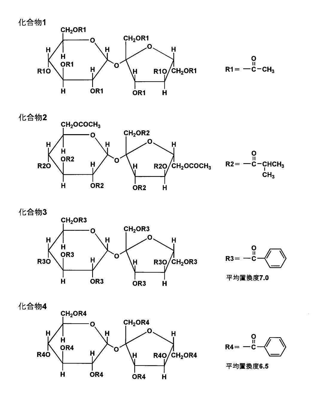
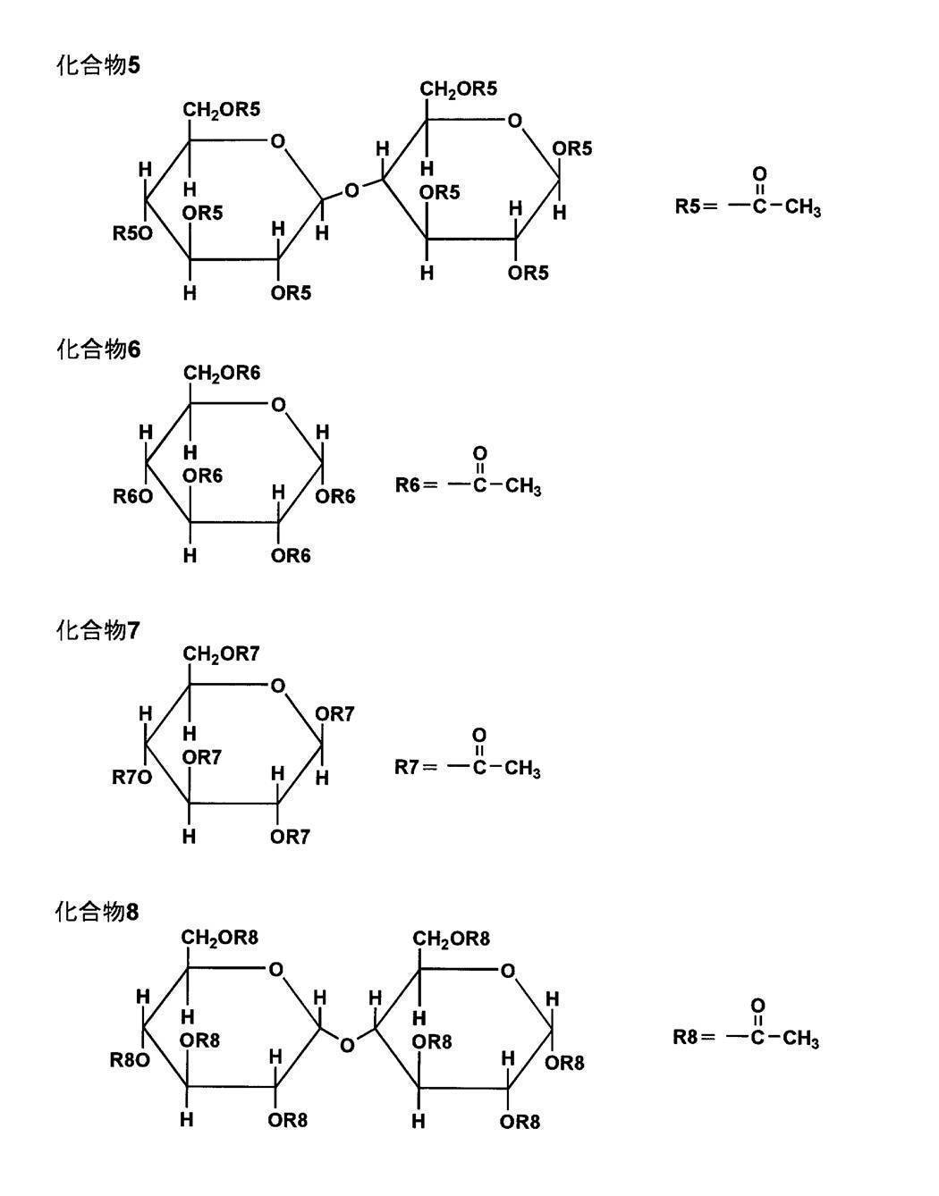
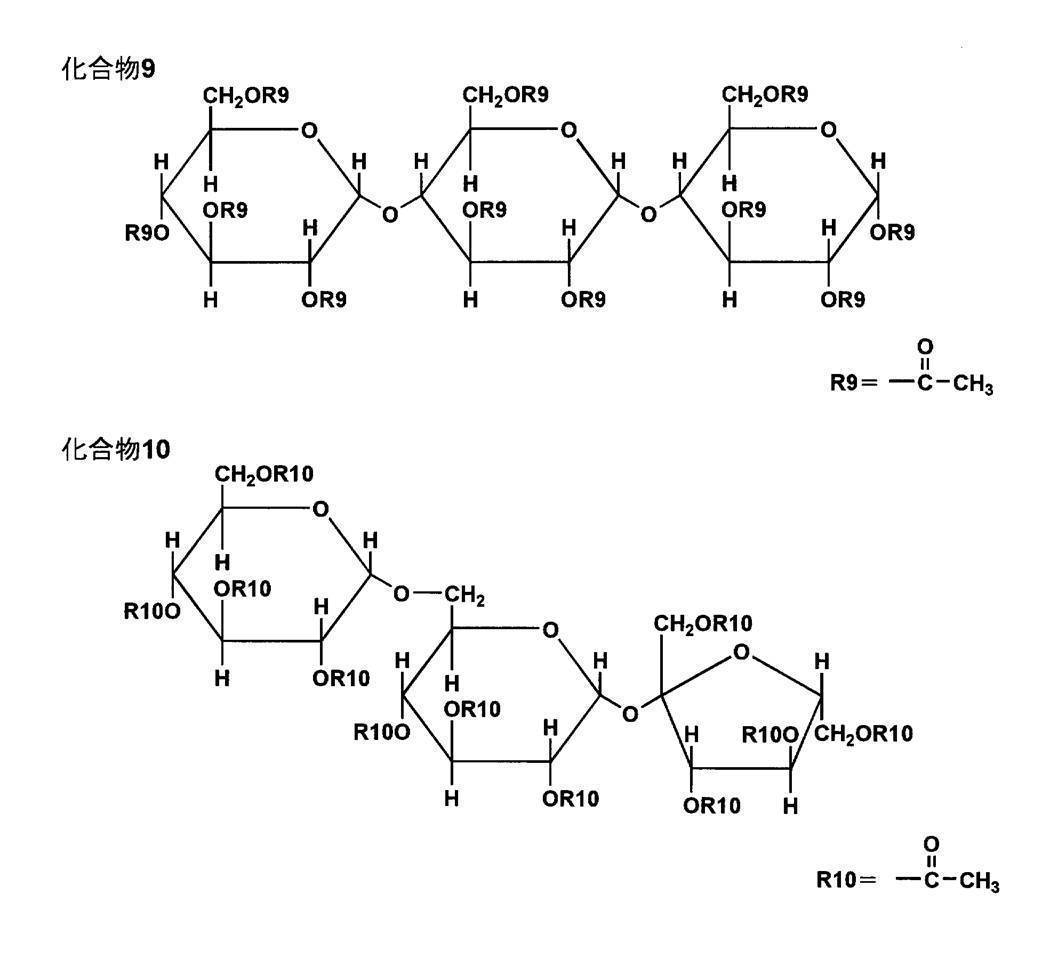

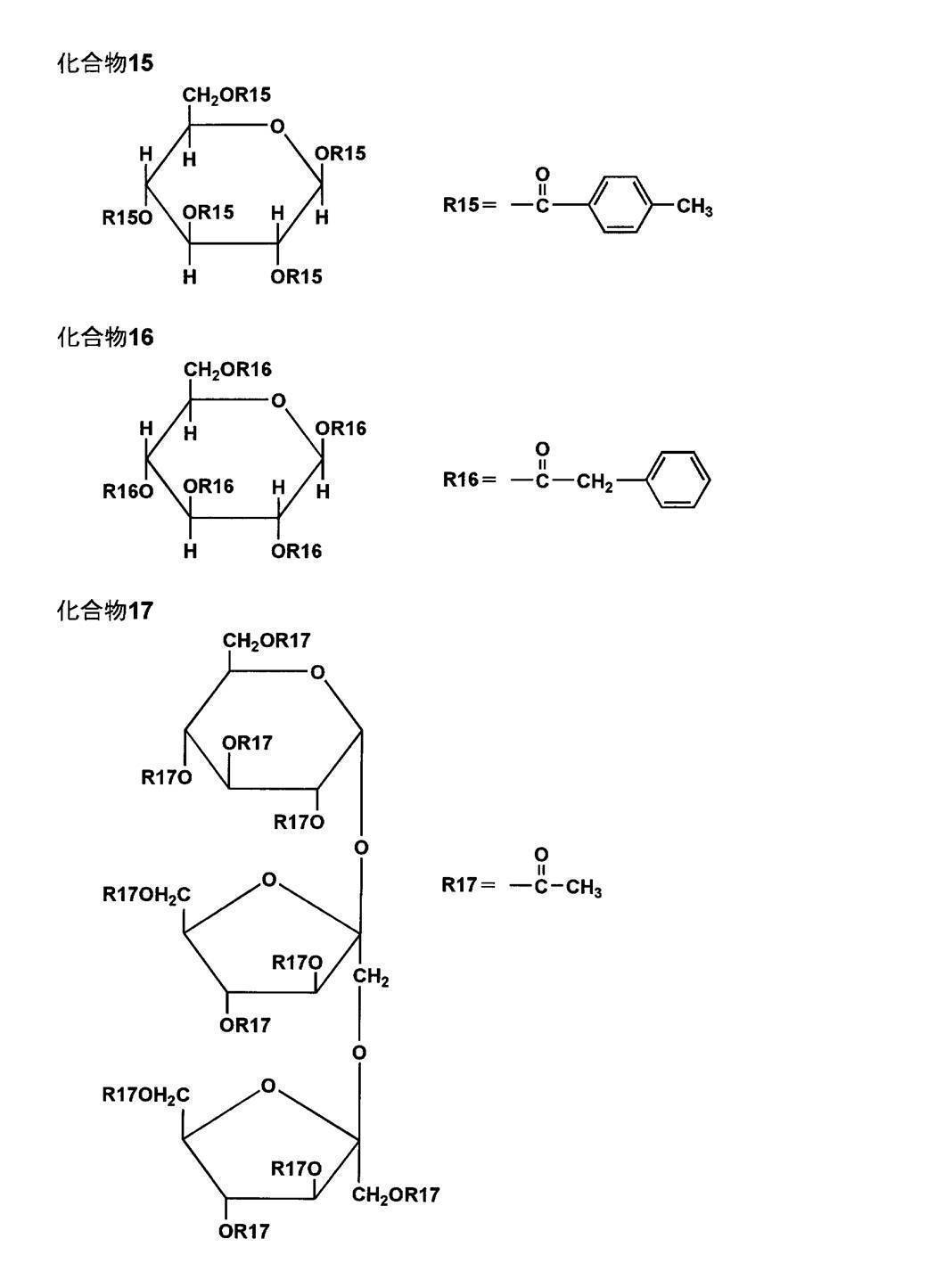
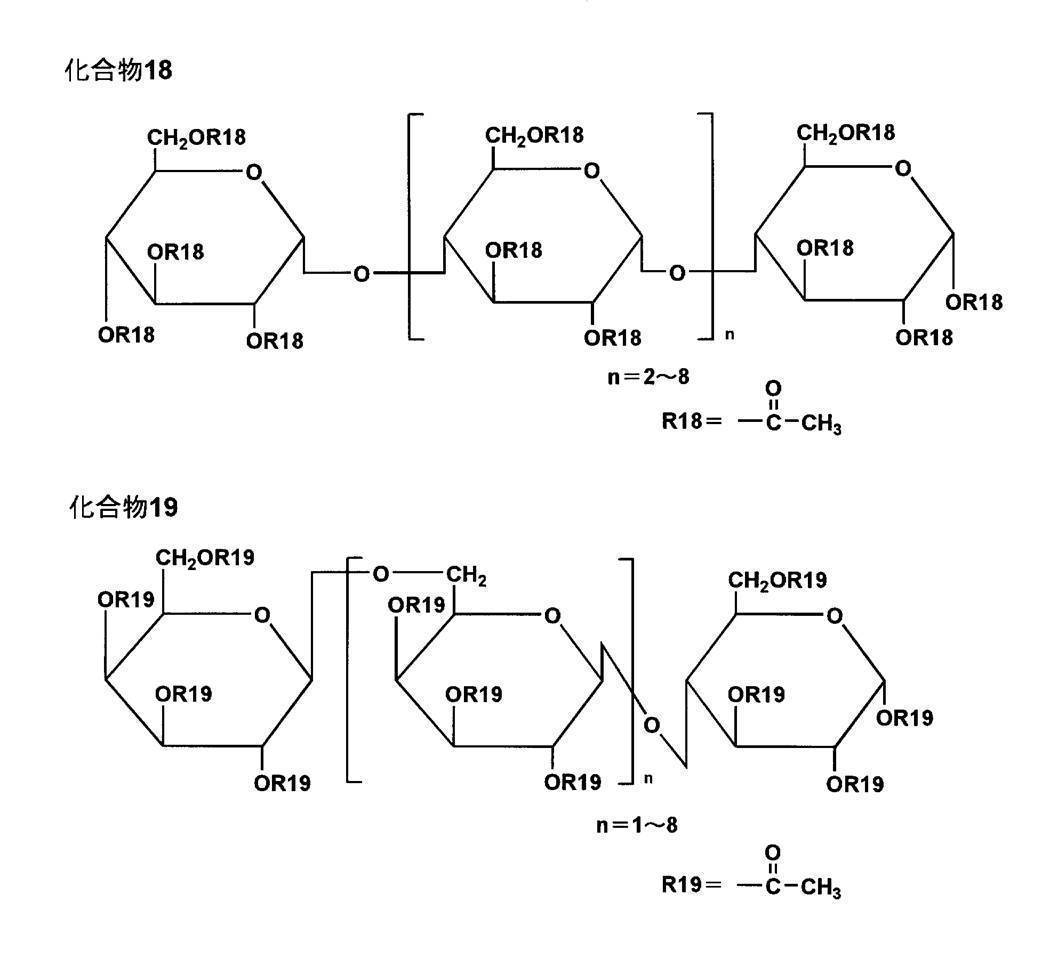
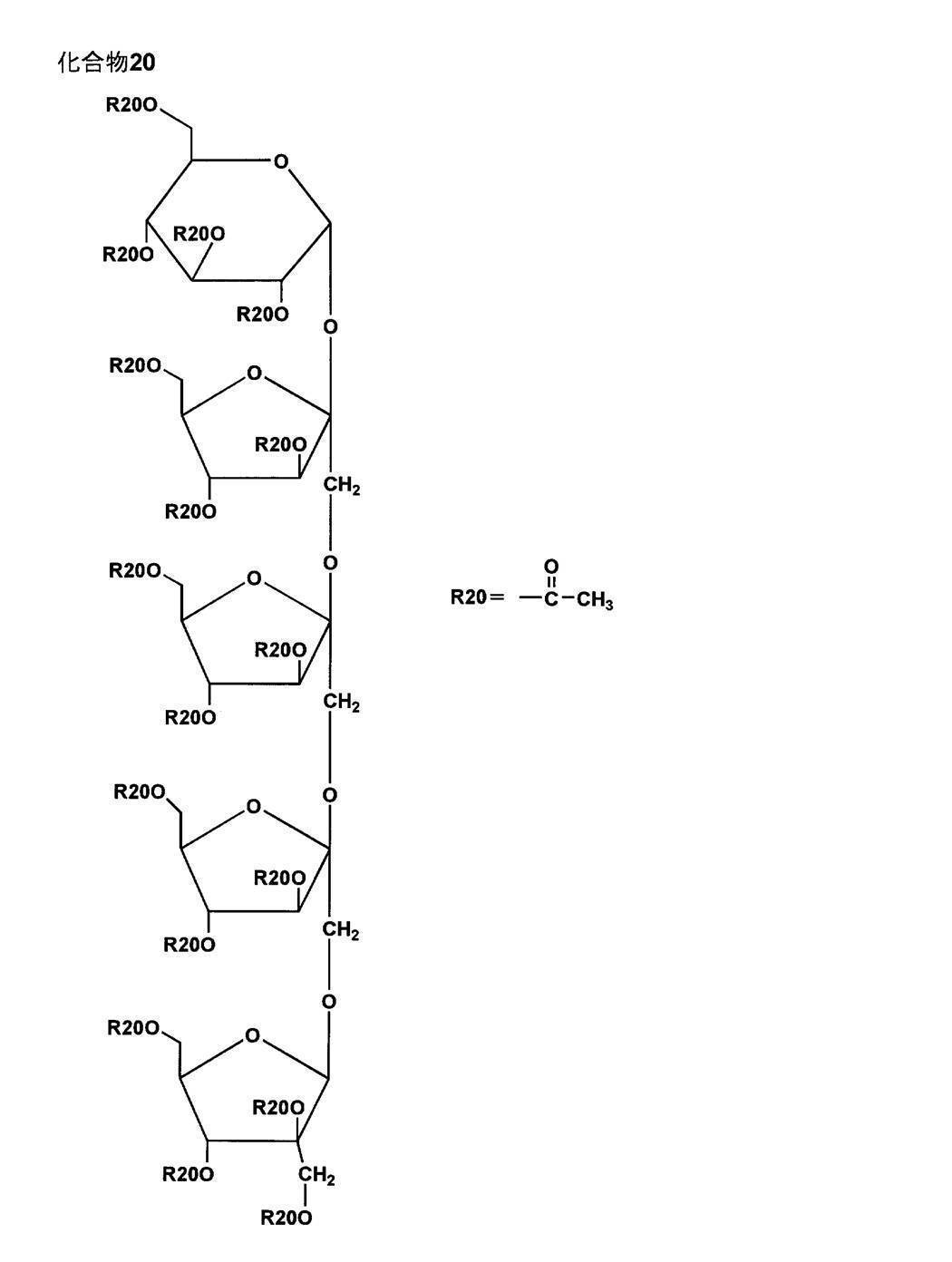

本発明のセルロースエステルフィルムは、位相差値の変動を抑制して、表示品位を安定化する為に、エステル化合物を、セルロースエステルフィルムの1~30質量%含むことが好ましく、特には、5~30質量%含むことが好ましい。
〈一般式(c)に示す構造の化合物〉
本発明で用いられる第2のセルロースエステルフィルムには、一般式(c)を用いることが好ましい。一般式(c)に示す構造の化合物は、ポリエステル系可塑剤であり、分子内に芳香環またはシクロアルキル環を有するポリエステル系可塑剤を用いることができる。
本発明で用いられる第2のセルロースエステルフィルムには、一般式(c)を用いることが好ましい。一般式(c)に示す構造の化合物は、ポリエステル系可塑剤であり、分子内に芳香環またはシクロアルキル環を有するポリエステル系可塑剤を用いることができる。
一般式(c) B-(G-A)n-G-B
(式中、Bはアリールカルボン酸残基、Gは炭素数2~12のアルキレングリコール残基または炭素数6~12のアリールグリコール残基または炭素数が4~12のオキシアルキレングリコール残基、Aは炭素数4~12のアルキレンジカルボン酸残基または炭素数6~12のアリールジカルボン酸残基を表し、またnは1以上の整数を表す。)
一般式(c)中、Bで示されるベンゼンモノカルボン酸残基とGで示されるアルキレングリコール残基またはオキシアルキレングリコール残基またはアリールグリコール残基、Aで示されるアルキレンジカルボン酸残基またはアリールジカルボン酸残基とから構成されるものであり、通常のポリエステル系可塑剤と同様の反応により得られる。
(式中、Bはアリールカルボン酸残基、Gは炭素数2~12のアルキレングリコール残基または炭素数6~12のアリールグリコール残基または炭素数が4~12のオキシアルキレングリコール残基、Aは炭素数4~12のアルキレンジカルボン酸残基または炭素数6~12のアリールジカルボン酸残基を表し、またnは1以上の整数を表す。)
一般式(c)中、Bで示されるベンゼンモノカルボン酸残基とGで示されるアルキレングリコール残基またはオキシアルキレングリコール残基またはアリールグリコール残基、Aで示されるアルキレンジカルボン酸残基またはアリールジカルボン酸残基とから構成されるものであり、通常のポリエステル系可塑剤と同様の反応により得られる。
本発明で使用されるポリエステル系可塑剤のアリールカルボン酸成分としては、例えば、安息香酸、パラターシャリブチル安息香酸、オルソトルイル酸、メタトルイル酸、パラトルイル酸、ジメチル安息香酸、エチル安息香酸、ノルマルプロピル安息香酸、アミノ安息香酸、アセトキシ安息香酸等があり、これらはそれぞれ1種または2種以上の混合物として使用することができる。
本発明で用いられる第2のセルロースエステルフィルムに好ましく用いることのできるポリエステル系可塑剤の炭素数2~12のアルキレングリコール成分としては、エチレングリコール、1,2-プロピレングリコール、1,3-プロピレングリコール、1,2-ブタンジオール、1,3-ブタンジオール、1,2-プロパンジオール、2-メチル1,3-プロパンジオール、1,4-ブタンジオール、1,5-ペンタンジオール、2,2-ジメチル-1,3-プロパンジオール(ネオペンチルグリコール)、2,2-ジエチル-1,3-プロパンジオール(3,3-ジメチロールペンタン)、2-n-ブチル-2-エチル-1,3プロパンジオール(3,3-ジメチロールヘプタン)、3-メチル-1,5-ペンタンジオール1,6-ヘキサンジオール、2,2,4-トリメチル1,3-ペンタンジオール、2-エチル1,3-ヘキサンジオール、2-メチル1,8-オクタンジオール、1,9-ノナンジオール、1,10-デカンジオール、1,12-オクタデカンジオール等があり、これらのグリコールは、1種または2種以上の混合物として使用される。
特に炭素数2~12のアルキレングリコールがセルロースエステルとの相溶性に優れているため、特に好ましい。
また、上記芳香族末端エステルの炭素数4~12のオキシアルキレングリコール成分としては、例えば、ジエチレングリコール、トリエチレングリコール、テトラエチレングリコール、ジプロピレングリコール、トリプロピレングリコール等があり、これらのグリコールは、1種または2種以上の混合物として使用できる。
芳香族末端エステルの炭素数4~12のアルキレンジカルボン酸成分としては、例えば、コハク酸、マレイン酸、フマール酸、グルタール酸、アジピン酸、アゼライン酸、セバシン酸、ドデカンジカルボン酸等があり、これらは、それぞれ1種または2種以上の混合物として使用される。炭素数6~12のアリーレンジカルボン酸成分としては、フタル酸、テレフタル酸、イソフタル酸、1,5ナフタレンジカルボン酸、1,4ナフタレンジカルボン酸等がある。
本発明に係る第2のセルロースエステルフィルムに使用されるポリエステル系可塑剤は、数平均分子量が、好ましくは300~1500、より好ましくは400~1000の範囲が好適である。また、その酸価は、0.5mgKOH/g以下、水酸基価は25mgKOH/g以下、より好ましくは酸価0.3mgKOH/g以下、水酸基価は15mgKOH/g以下のものである。
以下に、本発明に用いることのできる一般式(c)に示す構造の芳香族末端エステル系可塑剤の具体的化合物を示すが、本発明はこれに限定されない。
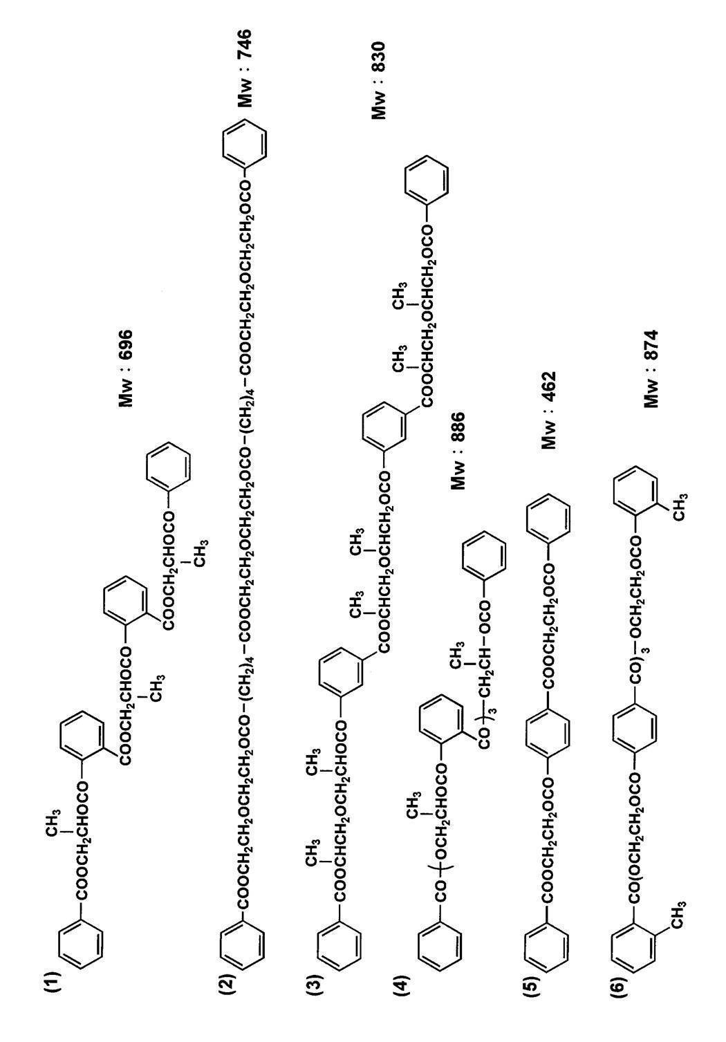
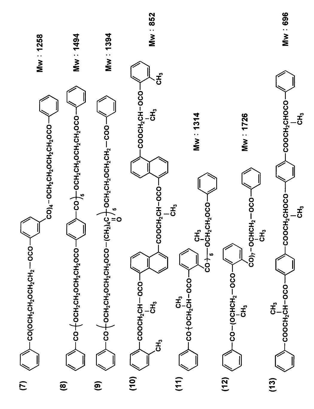
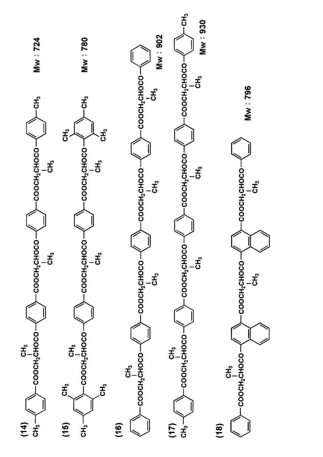

その他の以下にあげる可塑剤を併用してもよい。
例えば、リン酸エステル系可塑剤、フタル酸エステル系可塑剤、トリメリット酸エステル系可塑剤、ピロメリット酸系可塑剤、グリコレート系可塑剤、クエン酸エステル系可塑剤、ポリエステル系可塑剤、リン酸エステル系可塑剤では、トリフェニルホスフェート、トリクレジルホスフェート、クレジルジフェニルホスフェート、オクチルジフェニルホスフェート、ジフェニルビフェニルホスフェート、トリオクチルホスフェート、トリブチルホスフェート等、フタル酸エステル系可塑剤では、ジエチルフタレート、ジメトキシエチルフタレート、ジメチルフタレート、ジオクチルフタレート、ジブチルフタレート、ジ-2-エチルヘキシルフタレート、ブチルベンジルフタレート、ジフェニルフタレート、ジシクロヘキシルフタレート等、トリメリット酸系可塑剤では、トリブチルトリメリテート、トリフェニルトリメリテート、トリエチルトリメリテート等、ピロメリット酸エステル系可塑剤では、テトラブチルピロメリテート、テトラフェニルピロメリテート、テトラエチルピロメリテート等、グリコレート系可塑剤では、トリアセチン、トリブチリン、エチルフタリルエチルグリコレート、メチルフタリルエチルグリコレート、ブチルフタリルブチルグリコレート等、クエン酸エステル系可塑剤では、トリエチルシトレート、トリ-n-ブチルシトレート、アセチルトリエチルシトレート、アセチルトリ-n-ブチルシトレート、アセチルトリ-n-(2-エチルヘキシル)シトレート等を好ましく用いることができる。その他のカルボン酸エステルの例には、トリメチロールプロパントリベンゾエート、オレイン酸ブチル、リシノール酸メチルアセチル、セバシン酸ジブチル、種々のトリメリット酸エステルが含まれる。ポリエステル系可塑剤として脂肪族二塩基酸、脂環式二塩基酸、芳香族二塩基酸等の二塩基酸とグリコールの共重合ポリマーを用いることができる。
脂肪族二塩基酸としては特に限定されないが、アジピン酸、セバシン酸、フタル酸、テレフタル酸、1,4-シクロヘキシルジカルボン酸等を用いることができる。グリコールとしては、エチレングリコール、ジエチレングリコール、1,3-プロピレングリコール、1,2-プロピレングリコール、1,4-ブチレングリコール、1,3-ブチレングリコール、1,2-ブチレングリコール等を用いることができる。
これらの二塩基酸及びグリコールはそれぞれ単独で用いてもよいし、二種以上混合して用いてもよい。
これらの可塑剤の使用量は、フィルム性能、加工性等の点で、セルロースエステルに対して1質量%~20質量%が好ましく、特に好ましくは、3質量%~13質量%である。<その他の添加剤>
〈紫外線吸収剤〉
本発明に係るセルロースエステルフィルム(特に第1のセルロースエステルフィルム)には、紫外線吸収剤が好ましく用いられる。紫外線吸収剤としては、波長370nm以下の紫外線の吸収能に優れ、かつ良好な液晶表示性の観点から、波長400nm以上の可視光の吸収が少ないものが好ましく用いられる。
〈紫外線吸収剤〉
本発明に係るセルロースエステルフィルム(特に第1のセルロースエステルフィルム)には、紫外線吸収剤が好ましく用いられる。紫外線吸収剤としては、波長370nm以下の紫外線の吸収能に優れ、かつ良好な液晶表示性の観点から、波長400nm以上の可視光の吸収が少ないものが好ましく用いられる。
本発明に好ましく用いられる紫外線吸収剤の具体例としては、例えば、オキシベンゾフェノン系化合物、ベンゾトリアゾール系化合物、サリチル酸エステル系化合物、ベンゾフェノン系化合物、シアノアクリレート系化合物、ニッケル錯塩系化合物等が挙げられるが、これらに限定されない。
ベンゾトリアゾール系紫外線吸収剤としては、例えば下記の紫外線吸収剤を具体例として挙げるが、本発明はこれらに限定されない。
UV-1:2-(2′-ヒドロキシ-5′-メチルフェニル)ベンゾトリアゾール
UV-2:2-(2′-ヒドロキシ-3′,5′-ジ-tert-ブチルフェニル)ベンゾトリアゾール
UV-3:2-(2′-ヒドロキシ-3′-tert-ブチル-5′-メチルフェニル)ベンゾトリアゾール
UV-4:2-(2′-ヒドロキシ-3′,5′-ジ-tert-ブチルフェニル)-5-クロロベンゾトリアゾール
UV-5:2-(2′-ヒドロキシ-3′-(3″,4″,5″,6″-テトラヒドロフタルイミドメチル)-5′-メチルフェニル)ベンゾトリアゾール
UV-6:2,2-メチレンビス(4-(1,1,3,3-テトラメチルブチル)-6-(2H-ベンゾトリアゾール-2-イル)フェノール)
UV-7:2-(2′-ヒドロキシ-3′-tert-ブチル-5′-メチルフェニル)-5-クロロベンゾトリアゾール
UV-8:2-(2H-ベンゾトリアゾール-2-イル)-6-(直鎖及び側鎖ドデシル)-4-メチルフェノール(TINUVIN171、Ciba製)
UV-9:オクチル-3-〔3-tert-ブチル-4-ヒドロキシ-5-(クロロ-2H-ベンゾトリアゾール-2-イル)フェニル〕プロピオネートと2-エチルヘキシル-3-〔3-tert-ブチル-4-ヒドロキシ-5-(5-クロロ-2H-ベンゾトリアゾール-2-イル)フェニル〕プロピオネートの混合物(TINUVIN109、Ciba製)
また、ベンゾフェノン系紫外線吸収剤としては下記の具体例を示すが、本発明はこれらに限定されない。
UV-10:2,4-ジヒドロキシベンゾフェノン
UV-11:2,2′-ジヒドロキシ-4-メトキシベンゾフェノン
UV-12:2-ヒドロキシ-4-メトキシ-5-スルホベンゾフェノン
UV-13:ビス(2-メトキシ-4-ヒドロキシ-5-ベンゾイルフェニルメタン)
本発明で好ましく用いられる紫外線吸収剤としては、透明性が高く、偏光板や液晶の劣化を防ぐ効果に優れたベンゾトリアゾール系紫外線吸収剤やベンゾフェノン系紫外線吸収剤が好ましく、不要な着色がより少ないベンゾトリアゾール系紫外線吸収剤が特に好ましく用いられる。
UV-1:2-(2′-ヒドロキシ-5′-メチルフェニル)ベンゾトリアゾール
UV-2:2-(2′-ヒドロキシ-3′,5′-ジ-tert-ブチルフェニル)ベンゾトリアゾール
UV-3:2-(2′-ヒドロキシ-3′-tert-ブチル-5′-メチルフェニル)ベンゾトリアゾール
UV-4:2-(2′-ヒドロキシ-3′,5′-ジ-tert-ブチルフェニル)-5-クロロベンゾトリアゾール
UV-5:2-(2′-ヒドロキシ-3′-(3″,4″,5″,6″-テトラヒドロフタルイミドメチル)-5′-メチルフェニル)ベンゾトリアゾール
UV-6:2,2-メチレンビス(4-(1,1,3,3-テトラメチルブチル)-6-(2H-ベンゾトリアゾール-2-イル)フェノール)
UV-7:2-(2′-ヒドロキシ-3′-tert-ブチル-5′-メチルフェニル)-5-クロロベンゾトリアゾール
UV-8:2-(2H-ベンゾトリアゾール-2-イル)-6-(直鎖及び側鎖ドデシル)-4-メチルフェノール(TINUVIN171、Ciba製)
UV-9:オクチル-3-〔3-tert-ブチル-4-ヒドロキシ-5-(クロロ-2H-ベンゾトリアゾール-2-イル)フェニル〕プロピオネートと2-エチルヘキシル-3-〔3-tert-ブチル-4-ヒドロキシ-5-(5-クロロ-2H-ベンゾトリアゾール-2-イル)フェニル〕プロピオネートの混合物(TINUVIN109、Ciba製)
また、ベンゾフェノン系紫外線吸収剤としては下記の具体例を示すが、本発明はこれらに限定されない。
UV-10:2,4-ジヒドロキシベンゾフェノン
UV-11:2,2′-ジヒドロキシ-4-メトキシベンゾフェノン
UV-12:2-ヒドロキシ-4-メトキシ-5-スルホベンゾフェノン
UV-13:ビス(2-メトキシ-4-ヒドロキシ-5-ベンゾイルフェニルメタン)
本発明で好ましく用いられる紫外線吸収剤としては、透明性が高く、偏光板や液晶の劣化を防ぐ効果に優れたベンゾトリアゾール系紫外線吸収剤やベンゾフェノン系紫外線吸収剤が好ましく、不要な着色がより少ないベンゾトリアゾール系紫外線吸収剤が特に好ましく用いられる。
また、特開2001-187825号に記載されている分配係数が9.2以上の紫外線吸収剤は、長尺フィルムの面品質を向上させ、塗布性にも優れている。特に分配係数が10.1以上の紫外線吸収剤を用いることが好ましい。
また、特開平6-148430号に記載の一般式(1)または一般式(2)、特願2000-156039号の一般式(3)、(6)、(7)記載の高分子紫外線吸収剤(または紫外線吸収性ポリマー)も好ましく用いられる。高分子紫外線吸収剤としては、PUVA-30M(大塚化学(株)製)等が市販されている。
〈微粒子〉
本発明の第1及び第2のセルロースエステルフィルムには滑り性を付与するため、微粒子を添加することが好ましい。
本発明の第1及び第2のセルロースエステルフィルムには滑り性を付与するため、微粒子を添加することが好ましい。
微粒子の1次平均粒子径としては、20nm以下が好ましく、更に好ましくは、5~16nmであり、特に好ましくは、5~12nmである。
これらの微粒子は0.1~5μmの粒径の2次粒子を形成して位相差フィルムに含まれることが好ましく、好ましい平均粒径は0.1~2μmであり、更に好ましくは0.2~0.6μmである。これにより、フィルム表面に高さ0.1~1.0μm程度の凹凸を形成し、これによってフィルム表面に適切な滑り性を与えることができる。
本発明に用いられる微粒子の1次平均粒子径の測定は、透過型電子顕微鏡(倍率50万~200万倍)で粒子の観察を行い、粒子100個を観察し、粒子径を測定しその平均値をもって、1次平均粒子径とした。
微粒子の見掛比重としては、70g/リットル以上が好ましく、更に好ましくは、90~200g/リットルであり、特に好ましくは、100~200g/リットルである。見掛比重が大きい程、高濃度の分散液を作ることが可能になり、ヘイズ、凝集物が良化するため好ましく、また、本発明のように固形分濃度の高いドープを調製する際には、特に好ましく用いられる。
1次粒子の平均径が20nm以下、見掛比重が70g/リットル以上の二酸化珪素微粒子は、例えば、気化させた四塩化珪素と水素を混合させたものを1000~1200℃にて空気中で燃焼させることで得ることができる。また例えばアエロジル200V、アエロジルR972V(以上、日本アエロジル(株)製)の商品名で市販されており、それらを使用することができる。
上記記載の見掛比重は二酸化珪素微粒子を一定量メスシリンダーに採り、この時の重さを測定し、下記式で算出したものである。
見掛比重(g/リットル)=二酸化珪素質量(g)/二酸化珪素の容積(リットル)
本発明に用いられる微粒子の分散液を調製する方法としては、例えば以下に示すような3種類が挙げられる。
《調製方法A》
溶剤と微粒子を攪拌混合した後、分散機で分散を行う。これを微粒子分散液とする。微粒子分散液をドープ液に加えて攪拌する。
《調製方法B》
溶剤と微粒子を攪拌混合した後、分散機で分散を行う。これを微粒子分散液とする。別に溶剤に少量のセルロースエステルを加え、攪拌溶解する。これに前記微粒子分散液を加えて攪拌する。これを微粒子添加液とする。微粒子添加液をインラインミキサーでドープ液と十分混合する。
《調製方法C》
溶剤に少量のセルロースエステルを加え、攪拌溶解する。これに微粒子を加えて分散機で分散を行う。これを微粒子添加液とする。微粒子添加液をインラインミキサーでドープ液と十分混合する。
見掛比重(g/リットル)=二酸化珪素質量(g)/二酸化珪素の容積(リットル)
本発明に用いられる微粒子の分散液を調製する方法としては、例えば以下に示すような3種類が挙げられる。
《調製方法A》
溶剤と微粒子を攪拌混合した後、分散機で分散を行う。これを微粒子分散液とする。微粒子分散液をドープ液に加えて攪拌する。
《調製方法B》
溶剤と微粒子を攪拌混合した後、分散機で分散を行う。これを微粒子分散液とする。別に溶剤に少量のセルロースエステルを加え、攪拌溶解する。これに前記微粒子分散液を加えて攪拌する。これを微粒子添加液とする。微粒子添加液をインラインミキサーでドープ液と十分混合する。
《調製方法C》
溶剤に少量のセルロースエステルを加え、攪拌溶解する。これに微粒子を加えて分散機で分散を行う。これを微粒子添加液とする。微粒子添加液をインラインミキサーでドープ液と十分混合する。
調製方法Aは二酸化珪素微粒子の分散性に優れ、調製方法Cは二酸化珪素微粒子が再凝集しにくい点で優れている。中でも、上記記載の調製方法Bは二酸化珪素微粒子の分散性と、二酸化珪素微粒子が再凝集しにくい等、両方に優れている好ましい調製方法である。
《分散方法》
二酸化珪素微粒子を溶剤などと混合して分散する時の二酸化珪素の濃度は5質量%~30質量%が好ましく、10質量%~25質量%が更に好ましく、15~20質量%が最も好ましい。分散濃度は高い方が、添加量に対する液濁度は低くなる傾向があり、ヘイズ、凝集物が良化するため好ましい。
《分散方法》
二酸化珪素微粒子を溶剤などと混合して分散する時の二酸化珪素の濃度は5質量%~30質量%が好ましく、10質量%~25質量%が更に好ましく、15~20質量%が最も好ましい。分散濃度は高い方が、添加量に対する液濁度は低くなる傾向があり、ヘイズ、凝集物が良化するため好ましい。
使用される溶剤は低級アルコール類としては、好ましくはメチルアルコール、エチルアルコール、プロピルアルコール、イソプロピルアルコール、ブチルアルコール等が挙げられる。低級アルコール以外の溶媒としては特に限定されないが、セルロースエステルの製膜時に用いられる溶剤を用いることが好ましい。
セルロースエステルに対する二酸化珪素微粒子の添加量はセルロースエステル100質量部に対して、二酸化珪素微粒子は0.01質量部~5.0質量部が好ましく、0.05質量部~1.0質量部が更に好ましく、0.1質量部~0.5質量部が最も好ましい。添加量は多い方が、動摩擦係数に優れ、添加量が少ない方が、凝集物が少なくなる。
分散機は通常の分散機が使用できる。分散機は大きく分けてメディア分散機とメディアレス分散機に分けられる。二酸化珪素微粒子の分散にはメディアレス分散機がヘイズが低く好ましい。メディア分散機としてはボールミル、サンドミル、ダイノミルなどが挙げられる。
メディアレス分散機としては超音波型、遠心型、高圧型などがあるが、本発明においては高圧分散装置が好ましい。高圧分散装置は、微粒子と溶媒を混合した組成物を、細管中に高速通過させることで、高剪断や高圧状態など特殊な条件を作りだす装置である。
高圧分散装置で処理する場合、例えば、管径1~2000μmの細管中で装置内部の最大圧力条件が9.807MPa以上であることが好ましい。
更に好ましくは19.613MPa以上である。またその際、最高到達速度が100m/秒以上に達するもの、伝熱速度が420kJ/時間以上に達するものが好ましい。
上記のような高圧分散装置には、Microfluidics Corporation社製超高圧ホモジナイザ(商品名マイクロフルイダイザ)或いはナノマイザ社製ナノマイザがあり、他にもマントンゴーリン型高圧分散装置、例えば、イズミフードマシナリ製ホモジナイザ、三和機械(株)製UHN-01等が挙げられる。
また、微粒子を含むドープを流延支持体に直接接するように流延することが、滑り性が高く、ヘイズが低いフィルムが得られるので好ましい。
また、流延後に剥離して乾燥されロール状に巻き取られた後、ハードコート層や反射防止層等の機能性薄膜が設けられる。加工若しくは出荷されるまでの間、汚れや静電気によるゴミ付着等から製品を保護するために通常、包装加工がなされる。
この包装材料については、上記目的が果たせれば特に限定されないが、フィルムからの残留溶媒の揮発を妨げないものが好ましい。具体的には、ポリエチレン、ポリエステル、ポリプロピレン、ナイロン、ポリスチレン、紙、各種不織布等が挙げられる。繊維がメッシュクロス状になったものは、より好ましく用いられる。
<本発明の第1及び第2のセルロースエステルフィルム製造方法>
次に、本発明の第1及び第2のセルロースエステルフィルムの製造方法について詳細に説明する。
<本発明の第1及び第2のセルロースエステルフィルム製造方法>
次に、本発明の第1及び第2のセルロースエステルフィルムの製造方法について詳細に説明する。
本発明の第1及び第2のセルロースエステルフィルムは溶液流延法で製造されたフィルムであっても溶融流延法で製造されたフィルムであっても好ましく用いることができる。
本発明の第1及び第2のセルロースエステルフィルムの製造は、セルロースエステル及び添加剤を溶剤に溶解させてドープを調製する工程、ドープを無限に移行する無端の金属支持体上に流延する工程、流延したドープをウェブとして乾燥する工程、金属支持体から剥離する工程、延伸または幅保持する工程、更に乾燥する工程、仕上がったフィルムを巻取る工程により行われる。
ドープを調製する工程について述べる。ドープ中のセルロースエステルの濃度は、濃い方が金属支持体に流延した後の乾燥負荷が低減できて好ましいが、セルロースエステルの濃度が濃過ぎると濾過時の負荷が増えて、濾過精度が悪くなる。これらを両立する濃度としては、10~35質量%が好ましく、更に好ましくは、15~25質量%である。
ドープで用いられる溶剤は、単独で用いても2種以上を併用してもよいが、セルロースエステルの良溶剤と貧溶剤を混合して使用することが生産効率の点で好ましく、良溶剤が多い方がセルロースエステルの溶解性の点で好ましい。
良溶剤と貧溶剤の混合比率の好ましい範囲は、良溶剤が70~98質量%であり、貧溶剤が2~30質量%である。良溶剤、貧溶剤とは、使用するセルロースエステルを単独で溶解するものを良溶剤、単独で膨潤するかまたは溶解しないものを貧溶剤と定義している。
そのため、一般にセルロースエステルの平均酢化度(アセチル基置換度)によっては、良溶剤、貧溶剤が変わり、例えばアセトンを溶剤として用いる時には、セルロースエステルの酢酸エステル(アセチル基置換度2.4)、セルロースアセテートプロピオネートでは良溶剤になり、セルロースの酢酸エステル(アセチル基置換度2.8)では貧溶剤となる。
本発明に用いられる良溶剤は特に限定されないが、メチレンクロライド等の有機ハロゲン化合物やジオキソラン類、アセトン、酢酸メチル、アセト酢酸メチル等が挙げられる。特に好ましくはメチレンクロライドまたは酢酸メチルが挙げられる。
また、本発明に用いられる貧溶剤は特に限定されないが、例えば、メタノール、エタノール、n-ブタノール、シクロヘキサン、シクロヘキサノン等が好ましく用いられる。また、ドープ中には水が0.01~2質量%含有していることが好ましい。
また、セルロースエステルの溶解に用いられる溶媒は、フィルム製膜工程で乾燥によりフィルムから除去された溶媒を回収し、これを再利用して用いられる。
回収溶剤中に、セルロースエステルに添加されている添加剤、例えば可塑剤、紫外線吸収剤、ポリマー、モノマー成分などが微量含有されていることもあるが、これらが含まれていても好ましく再利用することができるし、必要であれば精製して再利用することもできる。
上記記載のドープを調製する時の、セルロースエステルの溶解方法としては、一般的な方法を用いることができる。加熱と加圧を組み合わせると常圧における沸点以上に加熱できる。
溶剤の常圧での沸点以上でかつ加圧下で溶剤が沸騰しない範囲の温度で加熱しながら攪拌溶解すると、ゲルやママコと呼ばれる塊状未溶解物の発生を防止するため好ましい。
また、セルロースエステルを貧溶剤と混合して湿潤あるいは膨潤させた後、更に良溶剤を添加して溶解する方法も好ましく用いられる。
加圧は窒素ガス等の不活性気体を圧入する方法や、加熱によって溶剤の蒸気圧を上昇させる方法によって行ってもよい。加熱は外部から行うことが好ましく、例えばジャケットタイプのものは温度コントロールが容易で好ましい。
溶剤を添加しての加熱温度は、高い方がセルロースエステルの溶解性の観点から好ましいが、加熱温度が高過ぎると必要とされる圧力が大きくなり生産性が悪くなる。
好ましい加熱温度は45~120℃であり、60~110℃がより好ましく、70℃~105℃が更に好ましい。また、圧力は設定温度で溶剤が沸騰しないように調整される。
もしくは冷却溶解法も好ましく用いられ、これによって酢酸メチルなどの溶媒にセルロースエステルを溶解させることができる。
次に、このセルロースエステル溶液を濾紙等の適当な濾過材を用いて濾過する。濾過材としては、不溶物等を除去するために絶対濾過精度が小さい方が好ましいが、絶対濾過精度が小さ過ぎると濾過材の目詰まりが発生し易いという問題がある。
このため絶対濾過精度0.008mm以下の濾材が好ましく、0.001~0.008mmの濾材がより好ましく、0.003~0.006mmの濾材が更に好ましい。
濾材の材質は特に制限はなく、通常の濾材を使用することができるが、ポリプロピレン、テフロン(登録商標)等のプラスチック製の濾材や、ステンレススティール等の金属製の濾材が繊維の脱落等がなく好ましい。
濾過により、原料のセルロースエステルに含まれていた不純物、特に輝点異物を除去、低減することが好ましい。
輝点異物とは、2枚の偏光板をクロスニコル状態にして配置し、その間に光学フィルム等を置き、一方の偏光板の側から光を当てて、他方の偏光板の側から観察した時に反対側からの光が漏れて見える点(異物)のことであり、径が0.01mm以上である輝点数が200個/cm2以下であることが好ましい。
より好ましくは100個/cm2以下であり、更に好ましくは50個/m2以下であり、更に好ましくは0~10個/cm2以下である。また、0.01mm以下の輝点も少ない方が好ましい。
ドープの濾過は通常の方法で行うことができるが、溶剤の常圧での沸点以上で、かつ加圧下で溶剤が沸騰しない範囲の温度で加熱しながら濾過する方法が、濾過前後の濾圧の差(差圧という)の上昇が小さく、好ましい。
好ましい温度は45~120℃であり、45~70℃がより好ましく、45~55℃であることが更に好ましい。
濾圧は小さい方が好ましい。濾圧は1.6MPa以下であることが好ましく、1.2MPa以下であることがより好ましく、1.0MPa以下であることが更に好ましい。
ここで、ドープの流延について説明する。
流延(キャスト)工程における金属支持体は、表面を鏡面仕上げしたものが好ましく、金属支持体としては、ステンレススティールベルトもしくは鋳物で表面をメッキ仕上げしたドラムが好ましく用いられる。
キャストの幅は1~4mとすることができる。流延工程の金属支持体の表面温度は-50℃~溶剤の沸点未満の温度で、温度が高い方がウェブの乾燥速度が速くできるので好ましいが、余り高過ぎるとウェブが発泡したり、平面性が劣化する場合がある。
好ましい支持体温度は0~55℃であり、25~50℃が更に好ましい。あるいは、冷却することによってウェブをゲル化させて残留溶媒を多く含んだ状態でドラムから剥離することも好ましい方法である。
金属支持体の温度を制御する方法は特に制限されないが、温風または冷風を吹きかける方法や、温水を金属支持体の裏側に接触させる方法がある。温水を用いる方が熱の伝達が効率的に行われるため、金属支持体の温度が一定になるまでの時間が短く好ましい。温風を用いる場合は目的の温度よりも高い温度の風を使う場合がある。
セルロースエステルフィルムが良好な平面性を示すためには、金属支持体からウェブを剥離する際の残留溶媒量は10~150質量%が好ましく、更に好ましくは20~40質量%または60~130質量%であり、特に好ましくは、20~30質量%または70~120質量%である。
本発明においては、残留溶媒量は下記式で定義される。
残留溶媒量(質量%)={(M-N)/N}×100
尚、Mはウェブまたはフィルムを製造中または製造後の任意の時点で採取した試料の質量で、NはMを115℃で1時間の加熱後の質量である。
尚、Mはウェブまたはフィルムを製造中または製造後の任意の時点で採取した試料の質量で、NはMを115℃で1時間の加熱後の質量である。
また、セルロースエステルフィルムの乾燥工程においては、ウェブを金属支持体より剥離し、更に乾燥し、残留溶媒量を1質量%以下にすることが好ましく、更に好ましくは0.1質量%以下であり、特に好ましくは0~0.01質量%以下である。
フィルム乾燥工程では一般にロール乾燥方式(上下に配置した多数のロールにウェブを交互に通し乾燥させる方式)やテンター方式でウェブを搬送させながら乾燥する方式が採られる。
本発明のセルロースエステルフィルムを作製するためには、ウェブの両端をクリップ等で把持するテンター方式で幅方向(横方向)に延伸を行うことが特に好ましい。剥離張力は300N/m以下で剥離することが好ましい。
ウェブを乾燥させる手段は特に制限なく、一般的に熱風、赤外線、加熱ロール、マイクロ波等で行うことができるが、簡便さの点で熱風で行うことが好ましい。
ウェブの乾燥工程における乾燥温度は40~200℃で段階的に高くしていくことが好ましい。
本発明に係るセルロースエステルフィルムは、幅1~4mのものが好ましく用いられる。特に幅1.4~4mのものが好ましく用いられ、特に好ましくは1.6~3mである。
本発の第2のセルロースエステルフィルムが目標とするリターデーション値Ro、Rtは、セルロースエステルフィルムが本発明の素材構成をとり、更に搬送張力の制御、延伸操作により屈折率制御を行うことで得ることができる。
フィルムの長手方向(製膜方向)及びそれとフィルム面内で直交する方向、即ち幅手方向に対して、逐次または同時に2軸延伸もしくは1軸延伸することができる。
互いに直交する2軸方向の延伸倍率は、それぞれ最終的には流延方向に0.8~1.5倍、幅方向に1.1~2.5倍の範囲とすることが好ましく、流延方向に0.8~1.0倍、幅方向に1.2~2.0倍に範囲で行うことが好ましい。
延伸温度は120℃~200℃が好ましく、さらに好ましくは150℃~200℃であり、さらに好ましくは150℃を超えて190℃以下で延伸するのが好ましい。
フィルム中の残留溶媒は20~0%が好ましく、さらに好ましくは15~0%で延伸するのが好ましい。
具体的には155℃で残留溶媒が11%で延伸する、あるいは155℃で残留溶媒が2%で延伸するのが好ましい。もしくは160℃で残留溶媒が11%で延伸するのが好ましく、あるいは160℃で残留溶媒が1%未満で延伸するのが好ましい。
ウェブを延伸する方法には特に限定はない。例えば、複数のロールに周速差をつけ、その間でロール周速差を利用して縦方向に延伸する方法、ウェブの両端をクリップやピンで固定し、クリップやピンの間隔を進行方向に広げて縦方向に延伸する方法、同様に横方向に広げて横方向に延伸する方法、あるいは縦横同時に広げて縦横両方向に延伸する方法などが挙げられる。もちろんこれ等の方法は、組み合わせて用いてもよい。
また、所謂テンター法の場合、リニアドライブ方式でクリップ部分を駆動すると滑らかな延伸を行うことができ、破断等の危険性が減少できるので好ましい。
製膜工程のこれらの幅保持あるいは横方向の延伸はテンターによって行うことが好ましく、ピンテンターでもクリップテンターでもよい。
本発明のセルロースエステルフィルムの遅相軸または進相軸がフィルム面内に存在し、製膜方向とのなす角をθ1とするとθ1は-1°以上+1°以下であることが好ましく、-0.5°以上+0.5°以下であることがより好ましい。
このθ1は配向角として定義でき、θ1の測定は、自動複屈折計KOBRA-21ADH(王子計測機器)を用いて行うことができる。θ1が各々上記関係を満たすことは、表示画像において高い輝度を得ること、光漏れを抑制または防止することに寄与でき、カラー液晶表示装置においては忠実な色再現を得ることに寄与できる。
〈本発明の第1及び第2のセルロースエステルフィルムの物性〉
本発明に係る第1、第2のセルロースエステルフィルムの透湿度は、40℃、90%RHで300~1800g/m2・24hが好ましく、更に400~1500g/m2・24hが好ましく、40~1300g/m2・24hが特に好ましい。透湿度はJIS Z 0208に記載の方法に従い測定することができる。
本発明に係る第1、第2のセルロースエステルフィルムの透湿度は、40℃、90%RHで300~1800g/m2・24hが好ましく、更に400~1500g/m2・24hが好ましく、40~1300g/m2・24hが特に好ましい。透湿度はJIS Z 0208に記載の方法に従い測定することができる。
本発明の第1及び第2のセルロースエステルフィルムの破断伸度は10~80%であることが好ましく20~50%であることが更に好ましい。
本発明の第1及び第2のセルロースエステルフィルムの可視光透過率は90%以上であることが好ましく、93%以上であることが更に好ましい。
本発明の第1及び第2のセルロースエステルフィルムのヘイズは1%未満であることが好ましく0~0.1%であることが特に好ましい。
本発明の第2のセルロースエスエルフィルムは、その一方の面とそれと反対側の面(フィルム表面、裏面ともいう)との屈折率差が、5×10⁻⁴以上5×10⁻³以下の範囲であることが好ましい。
これは薄膜偏光板にすると、偏光板のコシが弱くなり液晶セルに貼合する際に気泡の発生や位置ズレが発生し易くなる。その為、第2のセルロースエスエルフィルムに意図的なカールをつけて偏光板にコシを与えることにより、液晶セルに貼合する際の上記故障を低減することができる。
本発明の第1のセルロースエステルフィルムは視認側に好ましく配置されるフィルムであり、少なくとも一方の面にハードコート層や防眩層等の機能性層を設けることが好ましい。
(ハードコート層)
本発明に用いられる第1のセルロースエステルフィルムに機能性層としてハードコート層が設けられていることが好ましい。
本発明に用いられる第1のセルロースエステルフィルムに機能性層としてハードコート層が設けられていることが好ましい。
本発明に用いられるハードコート層は、少なくとも偏光板保護フィルムの一方の面に設けられる。本発明の偏光板保護フィルムは、該ハードコート層上に、反射防止層(高屈折率層、低屈折率層等)が設けられ反射防止フィルムを構成することが好ましい。ハードコート層としては、活性線硬化樹脂層が好ましく用いられる。
(防眩層)
防眩層は、防眩性を付与するため、透光性微粒子を含有することが好ましい。次に透光性微粒子について説明する。
防眩層は、防眩性を付与するため、透光性微粒子を含有することが好ましい。次に透光性微粒子について説明する。
〈透光性微粒子〉
透光性微粒子は2種類以上の微粒子から構成されることが好ましい。2種類以上の微粒子の構成としては、平均粒径が、0.01~1μm以下の第1の透光性微粒子と平均粒径2~6μmの第2の透光性微粒子との組み合わせが、本発明の目的効果を発揮する点から好ましい。
透光性微粒子は2種類以上の微粒子から構成されることが好ましい。2種類以上の微粒子の構成としては、平均粒径が、0.01~1μm以下の第1の透光性微粒子と平均粒径2~6μmの第2の透光性微粒子との組み合わせが、本発明の目的効果を発揮する点から好ましい。
透光性微粒子1の平均粒径は0.01~1μm、より好ましくは0.05μm~1μmである。透光性微粒子2の平均粒径は2~6μmが好ましく、より好ましくは3~6μmである。
第1の透光性微粒子の平均粒径を0.01~1μmとすることで、内部ヘイズをコントロールしやすく、またアルカリ浴による鹸化処理の膜強度の低下抑制やオゾン暴露条件下での膜強度の低下抑制効果がより良く発揮される。第2の透光性微粒子の平均粒径は、2~6μmとすることで、光の散乱角度分布が良好で、ディスプレイの文字ボケを引き起こす心配もない。
また、防眩層の膜厚も厚くならないためカールが大きくならず、素材コストも抑えることができる。なお、これら平均粒子径は、例えばレーザー回折式粒度分布測定装置により測定することができる。
平均粒径が2~6μmの第2の透光性微粒子としては、アクリル系粒子、スチレン系粒子またはアクリル-スチレン系粒子、メラミン系粒子、ベンゾグアナミン系粒子、シリカを主成分とする無機粒子が挙げられ、例えばフッ素含有アクリル樹脂微粒子、ポリ((メタ)アクリレート)粒子、架橋ポリ((メタ)アクリレート)粒子、ポリスチレン粒子、架橋ポリスチレン粒子、架橋ポリ(アクリル-スチレン)粒子が好ましく挙げられる。中でも、フッ素含有アクリル樹脂微粒子が本発明目的効果をより発揮する点から好ましい。
フッ素含有アクリル樹脂微粒子としては、例えばフッ素含有のアクリル酸エステルあるいはメタクリル酸エステルのモノマーまたはポリマーから形成された微粒子である。フッ素含有のアクリル酸エステルあるいはメタクリル酸エステルの具体例としては、1H,1H,3H-テトラフルオロプロピル(メタ)アクリレート、1H,1H,5H-オクタフルオロペンチル(メタ)アクリレート、1H,1H,7H-ドデカフルオロヘプチル(メタ)アクリレート、1H,1H,9H-ヘキサデカフルオロノニル(メタ)アクリレート、2,2,2-トリフルオロエチル(メタ)アクリレート、2,2,3,3,3-ペンタフルオロプロピル(メタ)アクリレート、2-(パーフルオロブチル)エチル(メタ)アクリレート、2-(パーフルオロヘキシル)エチル(メタ)アクリレート、2-(パーフルオロオクチル)エチル(メタ)アクリレート、2-パーフルオロデシルエチル(メタ)アクリレート、3-パーフルオロブチル-2-ヒドロキシプロピル(メタ)アクリレート、3-パーフルオロヘキシル-2-ヒドロキシプロピル(メタ)アクリレート、3-パーフルオロオクチル-2-ヒドロキシプロピル(メタ)アクリレート、2-(パーフルオロ-3-メチルブチル)エチル(メタ)アクリレート、2-(パーフルオロ-5-メチルヘキシル)エチル(メタ)アクリレート、2-(パーフルオロ-7-メチルオクチル)エチル(メタ)アクリレート、3-(パーフルオロ-3-メチルブチル-2-ヒドロキシプロピル(メタ)アクリレート、3-(パーフルオロ-5-メチルヘキシル)-2-ヒドロキシプロピル(メタ)アクリレート、3-(パーフルオロ-7-メチルオクチル)-2-ヒドロキシプロピル(メタ)アクリレート、1H-1-(トリフルオロメチル)トリフルオロエチル(メタ)アクリレート、1H,1H,3H-ヘキサフルオロブチル(メタ)アクリレート、トリフルオロエチルメタクリレート、テトラフルオロプロピルメタクリレート、パーフルオロオクチルエチルアクリレート、2-(パーフルオロブチル)エチル-α-フルオロアクリレートが挙げられる。
また、フッ素含有アクリル樹脂微粒子の中でも、2-(パーフルオロブチル)エチル-α-フルオロアクリレートからなる微粒子、フッ素含有ポリメチルメタクリレート微粒子、フッ素含有メタアクリル酸を架橋剤の存在下にビニル単量体と共重合させた微粒子が好ましく、さらに好ましくはフッ素含有ポリメチルメタクリレート微粒子である。
フッ素含有(メタ)アクリル酸と共重合可能なビニル単量体としては、ビニル基を有するものであればよく、具体的にはメタクリル酸メチル、メタクリル酸ブチル等のメタクリル酸アルキルエステル、アクリル酸メチル、アクリル酸エチル等のアクリル酸アルキルエステル、及びスチレン、α-メチルスチレン等のスチレン類等が挙げられ、これらは単独でまたは混合して用いることができる。
重合反応の際に用いられる架橋剤としては、特に限定されないが、2個以上の不飽和基を有するものを用いることが好ましく、例えばエチレングリコールジメタクリレート、ポリエチレングリコールジメタクリレート等の2官能性ジメタクリレートや、トリメチロールプロパントリメタクリレート、ジビニルベンゼン等が挙げられる。
なお、フッ素含有ポリメチルメタクリレート微粒子を製造するための重合反応は、ランダム共重合及びブロック共重合のいずれでもよい。具体的には、例えば特開2000-169658号公報に記載の方法なども挙げることができる。
市販品としては、根上工業製:MF-0043等の市販品が挙げられる。なお、これらのフッ素含有アクリル樹脂微粒子は、単独で用いてもよいが、2種以上を組み合わせて用いてもよい。また、これらのフッ素含有アクリル樹脂微粒子の状態は、粉体あるいはエマルジョン等、どのような状態で加えられても良い。
また、特開2004-83707号公報の段落0028~0055に記載のフッ素含有架橋微粒子を用いても良い。
ポリスチレン系粒子としては、例えば綜研化学製;SX-130H、SX-200H、SX-350H)、積水化成品工業製、SBXシリーズ(SBX-6、SBX-8)等の市販品を挙げられる。
メラミン系粒子としては、例えば、日本触媒製:ベンゾグアナミン・メラミン・ホルムアルデヒド縮合物(商品名:エポスター、グレード;M30、商品名:エポスターGP、グレード;H40~H110)、日本触媒製:メラミン・ホルムアルデヒド縮合物(商品名:エポスター、グレード;S12、S6、S、SC4)等の市販品を挙げられる。また、コアがメラミン系樹脂からなり、シェルがシリカで充填されたコア-シェル型の球状複合硬化メラミン樹脂粒子等も挙げられる。具体的には特開2006-171033号公報に記載の方法で作製することができ、日産化学工業製:メラミン樹脂・シリカ複合粒子(商品名;オプトビーズ)等の市販品を挙げられる。
ポリ((メタ)アクリレート)粒子、架橋ポリ((メタ)アクリレート)粒子としては、例えば、綜研化学製;MX150、MX300、日本触媒製;エポスターMA、グレード;MA1002、MA1004、MA1006、MA1010、エポスターMX(エマルジョン)、グレード;MX020W、MX030W、MX050W、MX100W、積水化成品工業製:MBXシリーズ(MBX-8、MBX12)等の市販品を挙げられる。
架橋ポリ(アクリル-スチレン)粒子の具体例としては、例えば日本ペイント製:FS-201、MG-351等の市販品が挙げられる。ベンゾグアナミン系粒子としては、例えば日本触媒製:ベンゾグアナミン・ホルムアルデヒド縮合物(商品名:エポスター、グレード;L15、M05、MS、SC25)等が挙げられる。
平均粒径が2~6μmの第2の透光性微粒子は防眩層を形成する塗工液の安定性及び分散液の分散性から、含有量としては、後述する活性エネルギー線硬化樹脂100質量部に対して、0.01~500質量部が好ましく、さらに好ましくは0.1~100質量部、特に好ましくは1~60質量部である。
平均粒子径が0.01~1μmの第1の透光性微粒子としては、アクリル系粒子、シリカを主成分とする無機粒子が挙げられる。シリカ粒子としては、日本アエロジル製、アエロジル200、200V、300、デグサ製、アエロジルOX50、TT600等、日本触媒社製、KEP-10、KEP-50、KEP-100等の商品名が挙げられる。また、コロイダルシリカを用いても良い。
コロイダルシリカとは、二酸化ケイ素をコロイド状に水または有機溶媒に分散させたものであり、特に限定はされないが球状、針状または数珠状である。このようなコロイダルシリカは市販されており、例えば、日産化学工業社のスノーテックスシリーズ、触媒化成工業社のカタロイド-Sシリーズ、バイエル社のレバシルシリーズ等が挙げられる。
また、アルミナゾルや水酸化アルミニウムでカチオン変性したコロイダルシリカやシリカの一次粒子を2価以上の金属イオンで粒子間を結合し数珠状に連結した数珠状コロイダルシリカも好ましく用いられる。
数珠状コロイダルシリカは日産化学工業社のスノーテックス-AKシリーズ、スノーテックス-PSシリーズ、スノーテックス-UPシリーズ等があげられ、具体的にはIPS-ST-L(イソプロパノールシリカゾル、粒子径40~50nm、シリカ濃度30%)、MEK-ST-MS(メチルエチルケトンシリカゾル、粒子径17~23nm、シリカ濃度35%)等、MEK-ST(メチルエチルケトンシリカゾル、粒子径10~15nm、シリカ濃度30%)、MEK-ST-L(メチルエチルケトンシリカゾル、粒子径40~50nm、シリカ濃度30%)、MEK-ST-UP(メチルエチルケトンシリカゾル、粒子径9~15nm(鎖状構造)、シリカ濃度20%)等が挙げられる。
アクリル系粒子としては、フッ素含有アクリル樹脂微粒子が挙げられ、例えば日本ペイント製:FS-701等の市販品が挙げられる。また、アクリル粒子として、例えば日本ペイント製:S-4000,アクリル-スチレン粒子として、例えば日本ペイント製:S-1200、MG-251等が挙げられる。
これら平均粒子径が0.01~1μmの第1の透光性微粒子のなかでもフッ素含有アクリル樹脂微粒子が本発明目的効果をより発揮する点から好ましい。
平均粒子径が0.01~1μmの第1の透光性微粒子は、防眩層を形成する塗工液の安定性及び分散液の分散性から、含有量としては、後述する透光性樹脂100質量部に対して、0.01~500質量部が好ましく、さらに好ましくは0.1~100質量部である。
また、平均粒径が0.01~1μmの第1の透光性微粒子(透光性微粒子1)と平均粒径が2~6μmの第2の透光性微粒子(透光性微粒子2)との含有比率は、透光性微粒子1:透光性微粒子2=1.0:1.0~3.0:1.0である。2種類の粒径が異なる微粒子を用い、かつ上記のような含有比率にすることで、アルカリ浴による鹸化処理後の膜強度の低下抑制やオゾン暴露下耐久試験後の膜強度の低下抑制に対してより良く効果を発揮する点で、好ましく、従来技術では知りえない効果である。
上記透光性微粒子は、粉体あるいはエマルジョン等どのような状態で加えられても良い。また、透光性微粒子の密度は、好ましくは10~1000mg/m2、より好ましくは100~700mg/m2である。
<ケン化処理条件>
本発明の偏光板に用いられる第1及び第2のセルロースエステルフィルムは、ケン化処理された後に偏光子に貼合されたものである。ケン化は、偏光板保護フィルム(第1のセルロースエステルフィルム)のケン化指数M1と、位相差フィルム(第2のセルロースエステルフィルム)のケン化指数M2との関係がM1>M2となるようなケン化条件で行われる必要がある。好ましくは(M1-M2)が45~175となる条件で、ケン化処理することが好ましい。
<ケン化処理条件>
本発明の偏光板に用いられる第1及び第2のセルロースエステルフィルムは、ケン化処理された後に偏光子に貼合されたものである。ケン化は、偏光板保護フィルム(第1のセルロースエステルフィルム)のケン化指数M1と、位相差フィルム(第2のセルロースエステルフィルム)のケン化指数M2との関係がM1>M2となるようなケン化条件で行われる必要がある。好ましくは(M1-M2)が45~175となる条件で、ケン化処理することが好ましい。
ケン化指数Mとはケン化効率の指標であり、数値が大きいほど効率が高くなる。アルカリ濃度、ケン化温度、ケン化時間の積で表現されるものである。
ケン化指数(M):ケン化用アルカリ溶液の濃度(mol%)×ケン化温度(×1/10℃)×ケン化時間(×1/10秒)
例えば、アルカリ濃度2mol%、ケン化温度50℃、ケン化時間90秒の場合、ケン化指数は、2×5×9=90となる。
例えば、アルカリ濃度2mol%、ケン化温度50℃、ケン化時間90秒の場合、ケン化指数は、2×5×9=90となる。
本発明の第1のセルロースエステルフィルムをケン化処理する際のケン化指数は90~220であることが好ましく、より好ましくは90~180である。
また、本発明の第2のセルロースエステルフィルムをケン化処理する際のケン化指数は5~45が好ましい。偏光板保護フィルム及び位相差フィルムのケン化指数を上述の範囲とすることで、偏光子との接着性を十分に得ながら、本発明の偏光板を液晶表示装置に用いた際の、黒表示時のスジむらや、湿熱保存後の波状の画像ムラを低減するとともに、フィルムの溶出や添加剤の析出、貼合する際の皺、気泡の巻き込み等の問題を効果的に抑制することができる。
ケン化効率の観点では、アルカリ濃度ならば高いほうが良好であるが、大気中の炭酸ガスの吸収により反面経時での劣化(ph及び炭酸塩の沈殿)が大きく、ケン化温度についても高いほうが良好であるが同様に変動が大きく処理の均一性の観点で問題がある。
経時による劣化を抑える手段としてはケン化槽付近の炭酸濃度を低下させるために、減圧、不活性ガス等で覆うことも好ましい形態ではあるが、十分ではない場合がある。そこでケン化条件の変動が無く、管理しやすい時間と組み合わせ、指数化することにより、フィルムの性状の違いだけでなく、製造の変動まで考慮した安定化を実行することができる。また、ケン化液はアルカリ剤と水からなり、場合により界面活性剤及び相溶化剤が含有されていても良い。
アルカリ剤としては、第3リン酸ナトリウム、第3リン酸カリウム、第3リン酸アンモニウム、第二リン酸ナトリウム、第二リン酸カリウム、第二リン酸アンモニウム、炭酸アンモニウム、炭酸水素アンモニウム、ほう酸ナトリウム、ほう酸カリウム、ほう酸アンモニウム、水酸化ナトリウム、水酸化カリウム、水酸化リチウム、水酸化アンモニウムなどの無機アルカリ剤が挙げられる。また、有機アルカリ剤も用いられる。これらのアルカリ剤は単独または2種以上を組み合わせて併用してもよい。
これらのアルカリ剤の中でも、水酸化ナトリウム、水酸化カリウムが好ましく、ケン化液の安定性の観点からより好ましいのは水酸化カリウムである。
アルカリ溶液の溶媒は、水の単独溶媒、または水と有機溶媒との混合溶媒である。好ましい有機溶媒は、アルコール類、アルカノール類、グリコール化合物のモノエーテル類、ケトン類、アミド類、スルホキシド類、エーテル類が挙げられる。より好ましくは、エチレングリコール、プロピレングリコール、ブタンジオール、ペンタンジオール、ヘキサンジオール、グリセリンモノメチルエーテル、グリセリンモノエチルエーテル、シクロヘキサンジオール、シクロヘキサンジメタノール、ジエチレングリコール、ジプロピレングリコール等が挙げられる。
ケン化温度は、室温から80℃の範囲で選択することができるが、30~60℃であることが好ましい。
ケン化時間は、必要とするケン化性能、生産性との関係で適宜選択されるが、10~120秒、好ましくは10~100秒である。
<偏光板>
本発明の偏光板は、偏光子と、当該偏光子を挟持するように、総アシル置換度が2.8~3.0の範囲であるセルロースエステルからなる第1のセルロースエステルフィルム(偏光板保護フィルム)と、総アシル置換度が2.1~2.6の範囲であるセルロースエステルからなり、且つ、下記式であらわされるリターデーション値Roが30nm以上200nm以下、Rtが70nm以上300nm以下である第2のセルロースエステルフィルム(位相差フィルム)が貼合されてなる。
<偏光板>
本発明の偏光板は、偏光子と、当該偏光子を挟持するように、総アシル置換度が2.8~3.0の範囲であるセルロースエステルからなる第1のセルロースエステルフィルム(偏光板保護フィルム)と、総アシル置換度が2.1~2.6の範囲であるセルロースエステルからなり、且つ、下記式であらわされるリターデーション値Roが30nm以上200nm以下、Rtが70nm以上300nm以下である第2のセルロースエステルフィルム(位相差フィルム)が貼合されてなる。
特に、前記第1のセルロースエステルフィルム及び前記第2のセルロースエステルフィルムは、ケン化処理されており、ケン化条件を下記式で表されるケン化指数Mとして表したときに、前記第1セルロースエステルフィルムのケン化指数M1と、前記第2のセルロースエステルフィルムのケン化指数M2が、M1>M2とされることを特徴とする。
本発明の効果を得る上では、前記第1セルロースエステルフィルムのケン化指数M1と、前記第2のセルロースエステルフィルムのケン化指数M2が、M1>M2であることが必須であるが、ケン化指数の差が45~175であることが好ましく、更に好ましくは60~150である。
前述したように、この範囲でケン化処理を行うことにより、偏光子との接着性を十分に得ながら、本発明の偏光板を液晶表示装置に用いた際の、スジむらや、湿熱保存後の波状の画像ムラを低減するとともに、フィルムの溶出や添加剤の析出、貼合する際の皺、気泡の巻き込み等の問題を効果的に抑制することができる。第1のセルロースエステルフィルム、第2のセルロースエステルフィルム共にフィルム表面から溶出、添加剤の析出、接触角のばらつきの発生による、偏光板作製時の、乾燥、経時保存等環境変動、接着、均一性(凹凸)による偏光板のムラ、歪み、スジも効果的に防止することができる。
本発明の第1及び第2のセルロースエステルフィルムをケン化指数の異なる条件でケン化処理し、処理した当該フィルムを、本発明に係る偏光子に、完全鹸化型ポリビニルアルコール水溶液を用いて貼り合わせることが好ましい。
本発明の第1のセルロースエステルフィルムには市販のセルロースエステルフィルムを用いることもできる。例えば、市販のセルロースエステルフィルムとして、KC8UX2M、KC4UX、KC5UX、KC4UY、KC8UY、KC12UR、KC8UX-RHA(以上、コニカミノルタオプト(株)製)等が好ましく用いられる。
偏光板は、更に該偏光板の一方の面にプロテクトフィルムを、反対面にセパレートフィルムを貼合して構成することができる。プロテクトフィルム及びセパレートフィルムは偏光板出荷時、製品検査時等において偏光板を保護する目的で用いられる。
この場合、プロテクトフィルムは、偏光板の表面を保護する目的で貼合され、偏光板を液晶板へ貼合する面の反対面側に用いられる。また、セパレートフィルムは液晶板へ貼合する接着層をカバーする目的で用いられ、偏光板を液晶セルへ貼合する面側に用いられる。
この偏光板を用いることによって、高い表示性能の液晶表示装置を提供することができる。特に、直下型バックライトを使用した液晶表示装置において、環境変動が少なく、画面周辺部の光漏れが低減された液晶表示装置を得ることができる。
<表示装置>
本発明の偏光板を表示装置に用いることによって、種々の視認性に優れた本発明の表示装置を作製することができる。本発明の位相差フィルムはSTN、TN、OCB、HAN、VA(MVA、PVA)、IPSなどの各種駆動方式の液晶表示装置に用いることができる。
<表示装置>
本発明の偏光板を表示装置に用いることによって、種々の視認性に優れた本発明の表示装置を作製することができる。本発明の位相差フィルムはSTN、TN、OCB、HAN、VA(MVA、PVA)、IPSなどの各種駆動方式の液晶表示装置に用いることができる。
そして最も好ましくはVA(MVA,PVA)型液晶表示装置である。特に画面が30型以上の大画面の液晶表示装置にあっては効果が顕著であり、環境変動が少なく、画面周辺部の光漏れが低減された液晶表示装置を得ることができる。
本発明の偏光板を用いた液晶表示装置に用いられるバックライトはサイドライト型であっても直下型であっても、これらを組み合わせたものであってもよいが、直下型バックライトであることが好ましい。
特に好ましい直下型バックライトは、赤色(R)LED、緑色(G)LED、及び青色(B)LEDを有するカラー液晶表示装置用LEDバックライトであって、例えば、上記赤色(R)LEDのピーク波長が610nm以上であり、上記緑色(G)LEDのピーク波長が530±10nmの範囲内であり、上記青色(B)LEDのピーク波長が480nm以下であるものが好ましく用いられる。ピーク波長が上記範囲内の緑色(G)LEDの種類としては、例えば、DG1112H(スタンレー電気(株)製)、UG1112H(スタンレー電気(株)製)、E1L51-3G(豊田合成(株)製)、E1L49-3G(豊田合成(株)製)、NSPG500S(日亜化学工業(株)製)等が挙げられる。
赤色(R)LEDとして用いられるLEDの種類としては、例えばFR1112H(スタンレー電気(株)製)、FR5366X(スタンレー電気(株)製)、NSTM515AS(日亜化学工業(株)製)、GL3ZR2D1COS(シャープ(株)製)、GM1JJ35200AE(シャープ(株)製)等が挙げられる。
青色(B)LEDとして用いられるLEDの種類としては、DB1112H(スタンレー電気(株)製)、DB5306X(スタンレー電気(株)製)、E1L51-3B(豊田合成(株)製)、E1L4E-SB1A(豊田合成(株)製)、NSPB630S(日亜化学工業(株)製)、NSPB310A(日亜化学工業(株)製)等が挙げられる。
上述した3色のLEDを組み合わせてバックライトとすることができる。或いは白色LEDを用いることもできる。
このほか、直下型バックライト(若しくは直下方式)としては、特開2001-281656号に記載の直下型バックライトや、特開2001-305535号記載のLED等の点状光源を使用した直下型バックライト、特開2002-311412号記載の直下方式のバックライトなどが挙げられるが特にこれらのみに限定されるわけではない。
以下に実施例を挙げて本発明を具体的に説明するが、本発明はこれらに限定されるものではない。なお、実施例中の「%」及び「部」は、特に断りのない限りそれぞれ「質量%」及び「質量部」を表す。
実施例1
《第2のセルロースエステルフィルムの作製》
(第2のセルロースエステルフィルム101の作製)
セルロースエステルについては、表1に示す置換度及び置換基の種類を変化させたものを用いた。
実施例1
《第2のセルロースエステルフィルムの作製》
(第2のセルロースエステルフィルム101の作製)
セルロースエステルについては、表1に示す置換度及び置換基の種類を変化させたものを用いた。

〈微粒子分散液〉
微粒子(アエロジルR972V(日本アエロジル株式会社製))
11質量部
(一次粒子の平均径16nm、見掛け比重90g/リットル)
エタノール 89質量部
以上をディゾルバーで50分間攪拌混合した後、マントンゴーリンで分散を行った。
微粒子(アエロジルR972V(日本アエロジル株式会社製))
11質量部
(一次粒子の平均径16nm、見掛け比重90g/リットル)
エタノール 89質量部
以上をディゾルバーで50分間攪拌混合した後、マントンゴーリンで分散を行った。
〈微粒子添加液〉
メチレンクロライドを入れた溶解タンクにセルロースエステルAを添加し、加熱して完全に溶解させた後、これを安積濾紙(株)製の安積濾紙No.244を使用して濾過した。濾過後のセルロースエステル溶液を充分に攪拌しながら、ここに上記微粒子分散液をゆっくりと添加した。更に、二次粒子の粒径が所定の大きさとなるようにアトライターにて分散を行った。これを日本精線(株)製のファインメットNFで濾過し、微粒子添加液を調製した。
メチレンクロライドを入れた溶解タンクにセルロースエステルAを添加し、加熱して完全に溶解させた後、これを安積濾紙(株)製の安積濾紙No.244を使用して濾過した。濾過後のセルロースエステル溶液を充分に攪拌しながら、ここに上記微粒子分散液をゆっくりと添加した。更に、二次粒子の粒径が所定の大きさとなるようにアトライターにて分散を行った。これを日本精線(株)製のファインメットNFで濾過し、微粒子添加液を調製した。
メチレンクロライド 99質量部
セルロースエステルD 4質量部
微粒子分散液 11質量部
下記組成の主ドープ液を調製した。まず加圧溶解タンクにメチレンクロライドとエタノールを添加した。溶剤の入った加圧溶解タンクにセルロースエステルCを攪拌しながら投入した。これを加熱し、攪拌しながら、完全に溶解し、更に可塑剤及び紫外線吸収剤を添加、溶解させた。これを安積濾紙(株)製の安積濾紙No.244を使用して濾過し、主ドープ液を調製した。
セルロースエステルD 4質量部
微粒子分散液 11質量部
下記組成の主ドープ液を調製した。まず加圧溶解タンクにメチレンクロライドとエタノールを添加した。溶剤の入った加圧溶解タンクにセルロースエステルCを攪拌しながら投入した。これを加熱し、攪拌しながら、完全に溶解し、更に可塑剤及び紫外線吸収剤を添加、溶解させた。これを安積濾紙(株)製の安積濾紙No.244を使用して濾過し、主ドープ液を調製した。
主ドープ液100質量部と微粒子添加液5質量部となるように加えて、インラインミキサー(東レ静止型管内混合機 Hi-Mixer、SWJ)で十分に混合し、次いでベルト流延装置を用い、幅2mのステンレスバンド支持体に均一に流延した。
ステンレスバンド支持体上で、残留溶媒量が110%になるまで溶媒を蒸発させ、ステンレスバンド支持体から剥離した。剥離の際に張力をかけて縦(MD)延伸倍率が1.1倍となるように延伸し、次いで、テンターでウェブ両端部を把持し、幅手(TD)方向の延伸倍率が1.3倍となるように延伸した。延伸後、その幅を維持したまま数秒間保持し、幅方向の張力を緩和させた後幅保持を解放し、更に125℃に設定された第3乾燥ゾーンで30分間搬送させて乾燥を行い、幅1.5m、かつ端部に幅1cm、高さ8μmのナーリングを有する膜厚50μmの第2のセルロースエステルフィルム101を作製した。
〈主ドープ液の組成〉
メチレンクロライド 390質量部
エタノール 80質量部
セルロースエステルD 100質量部
可塑剤:エステル化合物 化合物4 10質量部
可塑剤:芳香族末端エステル系可塑剤(1) 2.5質量部
ドープ液の組成(セルロースエステル)、を表2に記載のように変更した以外は、上記と同様にして位相差フィルム(第2のセルロースエステルフィルム)102~110を作製した。
メチレンクロライド 390質量部
エタノール 80質量部
セルロースエステルD 100質量部
可塑剤:エステル化合物 化合物4 10質量部
可塑剤:芳香族末端エステル系可塑剤(1) 2.5質量部
ドープ液の組成(セルロースエステル)、を表2に記載のように変更した以外は、上記と同様にして位相差フィルム(第2のセルロースエステルフィルム)102~110を作製した。
得られた位相差フィルム101~110について、下記測定により面内リターデーション値Ro、厚み方向のリターデーション値Rt及び表裏面の屈折率を測定し、結果を表2に示した。
〈リターデーション値の測定〉
Ro=(nx-ny)×d
Rt=((nx+ny)/2-nz)×d
(式中、nx、ny、nzはそれぞれ屈折率楕円体の主軸x、y、z方向の屈折率を表し、かつ、nx、nyはフィルム面内方向の屈折率を、nzはフィルムの厚み方向の屈折率を表す。また、nx>nyであり、dはフィルムの厚み(nm)を表す。)
アッベ屈折率計(1T)に偏光板付き接眼鏡を付け、分光光源を用いて位相差フィルムの両方の面のフィルム面内の一方向とそれに直行する方向及びフィルム面に垂直方向の屈折率を測定し、それらからの平均値より平均屈折率を求めた。また、市販のマイクロメーターを用いてフィルムの厚さを測定した。
Ro=(nx-ny)×d
Rt=((nx+ny)/2-nz)×d
(式中、nx、ny、nzはそれぞれ屈折率楕円体の主軸x、y、z方向の屈折率を表し、かつ、nx、nyはフィルム面内方向の屈折率を、nzはフィルムの厚み方向の屈折率を表す。また、nx>nyであり、dはフィルムの厚み(nm)を表す。)
アッベ屈折率計(1T)に偏光板付き接眼鏡を付け、分光光源を用いて位相差フィルムの両方の面のフィルム面内の一方向とそれに直行する方向及びフィルム面に垂直方向の屈折率を測定し、それらからの平均値より平均屈折率を求めた。また、市販のマイクロメーターを用いてフィルムの厚さを測定した。
自動複屈折計KOBRA-21ADH(王子計測機器(株)製)を用いて、23℃、55%RHの環境下24時間放置したフィルムにおいて、同環境下、波長が590nmにおけるフィルムのリターデーション測定を行った。上述の平均屈折率と膜厚を上記式に入力し、面内リターデーション値(Ro)及び厚み方向のリターデーション値(Rt)の値を得た。
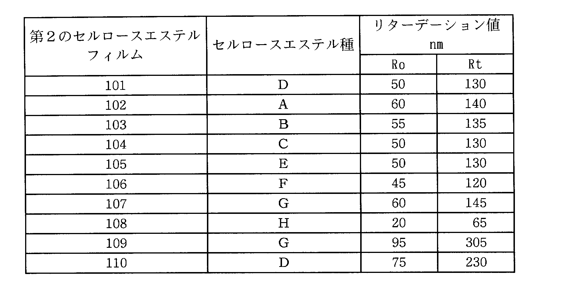
《第1のセルロースエステルフィルムの作製》
(第1のセルロースエステルフィルム201の作製)
(二酸化珪素分散液)
アエロジル972V(日本アエロジル(株)製) 12質量部
(一次粒子の平均径16nm、見掛け比重90g/リットル)
エタノール 88質量部
以上をディゾルバーで30分間撹拌混合した後、マントンゴーリンで分散を行った。二酸化珪素分散液に88質量部のメチレンクロライドを撹拌しながら投入し、ディゾルバーで30分間撹拌混合し、二酸化珪素分散希釈液を作製した。
(インライン添加液の作製)
チヌビン109(チバ・ジャパン(株)製) 11質量部
チヌビン171(チバ・ジャパン(株)製) 5質量部
メチレンクロライド 100質量部
以上を密閉容器に投入し、加熱し、撹拌しながら、完全に溶解し、濾過した。
(第1のセルロースエステルフィルム201の作製)
(二酸化珪素分散液)
アエロジル972V(日本アエロジル(株)製) 12質量部
(一次粒子の平均径16nm、見掛け比重90g/リットル)
エタノール 88質量部
以上をディゾルバーで30分間撹拌混合した後、マントンゴーリンで分散を行った。二酸化珪素分散液に88質量部のメチレンクロライドを撹拌しながら投入し、ディゾルバーで30分間撹拌混合し、二酸化珪素分散希釈液を作製した。
(インライン添加液の作製)
チヌビン109(チバ・ジャパン(株)製) 11質量部
チヌビン171(チバ・ジャパン(株)製) 5質量部
メチレンクロライド 100質量部
以上を密閉容器に投入し、加熱し、撹拌しながら、完全に溶解し、濾過した。
これに二酸化珪素分散希釈液を36質量部、撹拌しながら加えて、さらに30分間撹拌した後、下記セルローストリアセテート6質量部を撹拌しながら加えて、さらに60分間撹拌した後、アドバンテック東洋(株)のポリプロピレンワインドカートリッジフィルターTCW-PPS-1Nで濾過し、インライン添加液を調製した。
(ドープ液の調製)
セルローストリアセテート 100質量部
(Mn=150000、Mw=300000、アセチル基置換度2.91)
トリメチロールプロパントリベンゾエート 5.0質量部
エチルフタリルエチルグリコレート 5.5質量部
メチレンクロライド 440質量部
エタノール 40質量部
以上を密閉容器に投入し、加熱し、撹拌しながら、完全に溶解し、安積濾紙(株)製の安積濾紙No.24を使用して濾過し、ドープ液を調製した。
(ドープ液の調製)
セルローストリアセテート 100質量部
(Mn=150000、Mw=300000、アセチル基置換度2.91)
トリメチロールプロパントリベンゾエート 5.0質量部
エチルフタリルエチルグリコレート 5.5質量部
メチレンクロライド 440質量部
エタノール 40質量部
以上を密閉容器に投入し、加熱し、撹拌しながら、完全に溶解し、安積濾紙(株)製の安積濾紙No.24を使用して濾過し、ドープ液を調製した。
製膜ライン中で日本精線(株)製のファインメットNFでドープ液を濾過した。インライン添加液ライン中で、日本精線(株)製のファインメットNFでインライン添加液を濾過した。濾過したドープ液を100質量部に対し、濾過したインライン添加液を2質量部加えて、インラインミキサー(東レ静止型管内混合機 Hi-Mixer、SWJ)で十分混合し、次いで、ベルト流延装置を用い、温度35℃、1.8m幅でステンレスバンド支持体に均一に流延した。
ステンレスバンド支持体で、残留溶剤量が120%になるまで溶媒を蒸発させ、ステンレスバンド支持体上から剥離した。剥離したセルロースエステルのウェブを35℃で溶媒を蒸発させ、1.65m幅にスリットし、その後、テンターでTD方向(フィルムの搬送方向と直交する方向)に1.05倍に延伸しながら、135℃の乾燥温度で、乾燥させた。このときテンターで延伸を始めたときの残留溶剤量は30%であった。
その後、110℃、120℃の乾燥ゾーンを多数のロールで搬送させながら乾燥を終了させ、1.5m幅にスリットし、フィルム両端に幅15mm、平均高さ10μmのナーリング加工を施し、平均膜厚が60μmの第1のセルロースエステルフィルム201を作製した。
リターデーション値の測定をしたところ、Ro、Rtが各々3nm、50nmであった。
(第1のセルロースエステルフィルム202の作製)
セルロースエステルの膜厚を40μmに変更した以外は第1のセルロースエステルフィルム201の作製と同様にして、1.5m幅、平均膜厚40μmの第1のセルロースエステルフィルム202を作製した。
(第1のセルロースエステルフィルム202の作製)
セルロースエステルの膜厚を40μmに変更した以外は第1のセルロースエステルフィルム201の作製と同様にして、1.5m幅、平均膜厚40μmの第1のセルロースエステルフィルム202を作製した。
リターデーション値は、Ro、Rtが各々2nm、35nmであった。
(第1のセルロースエステルフィルム203の作製)
セルロースエステルの膜厚を50μmに変更した以外は第1のセルロースエステルフィルム201の作製と同様にして、1.5m幅、平均膜厚50μmの第1のセルロースエステルフィルム203を作製した。
(第1のセルロースエステルフィルム203の作製)
セルロースエステルの膜厚を50μmに変更した以外は第1のセルロースエステルフィルム201の作製と同様にして、1.5m幅、平均膜厚50μmの第1のセルロースエステルフィルム203を作製した。
リターデーション値は、Ro、Rtが各々3nm、45nmであった。
《偏光板の作製》
〈偏光板1の作製〉
上記作製した第2のセルロースエステルフィルム101及び第1のセルロースエステルフィルム202を下記工程1~5に従って偏光板1を作製した。
工程1:50℃、2mol%の水酸化ナトリウム溶液に90秒間浸漬し、次いで水洗し乾燥して、偏光子と貼合する側を鹸化した第2のセルロースエステルフィルム101及び第1のセルロースエステルフィルム202を得た。
工程2:前記偏光子を固形分2質量%のポリビニルアルコール接着剤槽中に1~2秒浸漬した。
工程3:工程2で偏光子に付着した過剰の接着剤を軽く拭き除き、これを工程1で処理した第2のセルロースエステルフィルム101及び第1のセルロースエステルフィルム202の上にのせて配置した。
工程4:工程3で積層した第2のセルロースエステルフィルムと偏光子と裏面側第1のセルロースエステルフィルムを圧力20~30N/cm2、搬送スピードは約2m/分で貼合した。
工程5:工程4で作製した偏光子と第2のセルロースエステルフィルム及び第1のセルロースエステルフィルムとを貼り合わせた試料を80℃の乾燥機中にて5分間乾燥し、偏光板1を作製した。
《偏光板の作製》
〈偏光板1の作製〉
上記作製した第2のセルロースエステルフィルム101及び第1のセルロースエステルフィルム202を下記工程1~5に従って偏光板1を作製した。
工程1:50℃、2mol%の水酸化ナトリウム溶液に90秒間浸漬し、次いで水洗し乾燥して、偏光子と貼合する側を鹸化した第2のセルロースエステルフィルム101及び第1のセルロースエステルフィルム202を得た。
工程2:前記偏光子を固形分2質量%のポリビニルアルコール接着剤槽中に1~2秒浸漬した。
工程3:工程2で偏光子に付着した過剰の接着剤を軽く拭き除き、これを工程1で処理した第2のセルロースエステルフィルム101及び第1のセルロースエステルフィルム202の上にのせて配置した。
工程4:工程3で積層した第2のセルロースエステルフィルムと偏光子と裏面側第1のセルロースエステルフィルムを圧力20~30N/cm2、搬送スピードは約2m/分で貼合した。
工程5:工程4で作製した偏光子と第2のセルロースエステルフィルム及び第1のセルロースエステルフィルムとを貼り合わせた試料を80℃の乾燥機中にて5分間乾燥し、偏光板1を作製した。
上記作製した位相差フィルム101~110及び偏光板保護フィルム201~203により挟持するように、下記表3に記載の組み合わせで、それぞれのケン化処理条件に従って貼合して偏光板1~44を作製した。
偏光板43,44については、上記工程1の水酸化ナトリウムを水酸化カリウムに変更することにより作製した。

《液晶表示装置の作製》
液晶パネルを以下のようにして作製し、偏光板及び液晶表示装置としての特性を評価した。
液晶パネルを以下のようにして作製し、偏光板及び液晶表示装置としての特性を評価した。
SONY製20型ディスプレイKLV-20AP2の予め貼合されていた両面の偏光板を剥がして、上記作製した偏光板1~44をそれぞれ液晶セルのガラス面に貼合した。
その際、偏光板の貼合の向きは、前記第2のセルロースエステルフィルムの面が液晶セル側となるように、かつ、予め貼合されていた偏光板と同一の方向に吸収軸が向くように行い、表4に示すように液晶表示装置1~44を各々作製した。
《評価》
(偏光板劣化:偏光度変化)
上記方法で作製した偏光板について先ず平行透過率と直交透過率を測定し、下記式に従って偏光度を算出した。その後各々の偏光板を60℃、90%の条件下で1000時間の強制劣化後、再度平行透過率と直交透過率を測定し、下記式に従って偏光度を算出した。偏光度変化量を偏光板劣化量として下記式により求めた。
《評価》
(偏光板劣化:偏光度変化)
上記方法で作製した偏光板について先ず平行透過率と直交透過率を測定し、下記式に従って偏光度を算出した。その後各々の偏光板を60℃、90%の条件下で1000時間の強制劣化後、再度平行透過率と直交透過率を測定し、下記式に従って偏光度を算出した。偏光度変化量を偏光板劣化量として下記式により求めた。
偏光度P(%)=((H0-H90)/(H0+H90))1/2×100
偏光度変化量=P0-P1000
H0:平行透過率
H90:直交透過率
P0:強制劣化前の偏光度
P1000:強制劣化1000時間後の偏光度
(偏光板寸法安定性)
偏光板の歪みを評価する目的で下記条件で偏光板寸法安定性を評価した。
偏光度変化量=P0-P1000
H0:平行透過率
H90:直交透過率
P0:強制劣化前の偏光度
P1000:強制劣化1000時間後の偏光度
(偏光板寸法安定性)
偏光板の歪みを評価する目的で下記条件で偏光板寸法安定性を評価した。
偏光板を23℃、55%RHの部屋で24時間調湿後、同部屋で、偏光板表面にフィルムの長手方向及び幅手方向に100mm間隔で2個の十文字の印を付けその寸法を正確に計りその距離をaとし、60℃、90%RHで120時間の処理を行い、再び23℃、55%RHの部屋で24時間調湿して2個の印の間の距離をカセトメーターで測定しその値をbとして、下記式により偏光板寸法安定性を寸法変化率として求めた。
寸法変化率(%)=〔(b-a)/a〕×100
水酸化カリウムにして作製した偏光板44は、水酸化ナトリウムにて作製した偏光板7と比較して、良好な結果となった。
(スジ)
上記作製した各液晶表示装置について、熱による劣化を見るために60℃の条件で300時間処理した後、23℃、55%RHに戻した。その後、電源を入れてバックライトを点灯させてから2時間後の黒表示時のスジを目視で下記基準で評価した。
◎:スジがまったくない
○:中央に弱いスジが存在する
△:中央から端部にかけて弱いスジが存在する
×:全面に強いスジが存在する。
水酸化カリウムにして作製した偏光板44は、水酸化ナトリウムにて作製した偏光板7と比較して、良好な結果となった。
(スジ)
上記作製した各液晶表示装置について、熱による劣化を見るために60℃の条件で300時間処理した後、23℃、55%RHに戻した。その後、電源を入れてバックライトを点灯させてから2時間後の黒表示時のスジを目視で下記基準で評価した。
◎:スジがまったくない
○:中央に弱いスジが存在する
△:中央から端部にかけて弱いスジが存在する
×:全面に強いスジが存在する。
スジは○以上の評価であれば、実用上問題ない。
《視認性の評価》
上記作製した各液晶表示装置について、60℃、90%RHの条件で100時間放置した後、23℃、55%RHに戻した。その後、表示装置の表面を目視で観察し下記の基準による評価をした。
◎:表面に波打ち状のムラは全く認められない
○:表面にわずかに波打ち状のムラが認められる
△:表面に細かい波打ち状のムラがやや認められる
×:表面に細かい波打ち状のムラが認められる
以上の評価結果を下記表4に示す。
《視認性の評価》
上記作製した各液晶表示装置について、60℃、90%RHの条件で100時間放置した後、23℃、55%RHに戻した。その後、表示装置の表面を目視で観察し下記の基準による評価をした。
◎:表面に波打ち状のムラは全く認められない
○:表面にわずかに波打ち状のムラが認められる
△:表面に細かい波打ち状のムラがやや認められる
×:表面に細かい波打ち状のムラが認められる
以上の評価結果を下記表4に示す。

上表から、本発明の、リターデーションの範囲を有する第2のセルロースエステルフィルム101~110を組み合わせ、ケン化指数45~175に調整された、本発明の偏光板及び液晶表示装置7~12、21~26、29~34、36、39、42、44は、環境条件が変動しても偏光板の偏光度変化、偏光板の歪みに優れ、かつ液晶表示装置として、スジ、視認性に優れていることが明らかである。
本発明の偏光板を用いたものは、平面性に優れていたのに対し、比較の表示装置は細かい波打ち状のムラが認められ、長時間見ていると目が疲れやすかった。
実施例2
実施例1で作製した偏光板35,36を各々液晶セルの一方の面に貼合し、該液晶セルの反対の面には下記偏光板45を作製して各々貼合し、実施例1と同様にして本発明の液晶表示装置45,46を作製した。
(偏光板45の作製)
実施例1の偏光板の作製と同様にして、第1のセルロースエステルフィルム203で両面から挟持するように貼合して、偏光板45を作製した。
《評価》
(視野角評価)
視野角評価は、上記で得られた本発明の偏光板を貼合した液晶パネルを、ELDIM社製EZ-contrastを用いて視野角を測定した。
実施例2
実施例1で作製した偏光板35,36を各々液晶セルの一方の面に貼合し、該液晶セルの反対の面には下記偏光板45を作製して各々貼合し、実施例1と同様にして本発明の液晶表示装置45,46を作製した。
(偏光板45の作製)
実施例1の偏光板の作製と同様にして、第1のセルロースエステルフィルム203で両面から挟持するように貼合して、偏光板45を作製した。
《評価》
(視野角評価)
視野角評価は、上記で得られた本発明の偏光板を貼合した液晶パネルを、ELDIM社製EZ-contrastを用いて視野角を測定した。
視野角の評価としては、液晶パネルの白表示と黒表示時のコントラスト比が10以上、及び反転を起こす領域を示すパネル面に対する法線方向からの傾き角の範囲を評価した。その結果、本発明の液晶表示装置46は、液晶表示装置極45と比較しては、極めて高い視野角改善特性を有しており、一枚の位相差フィルムの使用で十分な光学補償ができることが分かった。
Claims (8)
- 偏光子を第1のセルロースエステルフィルムと第2のセルロースエステルフィルムとで挟持してなる偏光板において、前記第1のセルロースエステルフィルムは、総アシル基置換度が2.8~3.0であるセルロースエステルからなり、前記第2のセルロースエステルフィルムは、総アシル基置換度が2.0~2.6であるセルロースエステルからなり、且つ、下記式であらわされるリターデーション値Roが30nm以上200nm以下であり、Rtが70nm以上300nm以下であり、前記第1のセルロースエステルフィルム及び前記第2のセルロースエステルフィルムは、ケン化処理条件を下記式で表されるケン化指数Mとして表したときに、前記第1のセルロースエステルフィルムのケン化指数M1と、前記第2のセルロースエステルフィルムのケン化指数M2が、M1>M2とされるケン化処理をされていることを特徴とする偏光板。
Ro=(nx-ny)×d
Rt={(nx+ny)/2-nz}×d
(式中、nxはフィルム面内の遅相軸方向の屈折率であり、nyはフィルム面内の進相軸方向の屈折率であり、nzはフィルムの厚み方向の屈折率であり、dはフィルムの厚さ(nm)である。)
ケン化指数(M):ケン化用アルカリ溶液の濃度(mol%)×ケン化温度(×1/10℃)×ケン化時間(×1/10秒) - 前記第2のセルロースエステルフィルムは、アセチル基置換度が2.0~2.6であるセルロースエステルからなることを特徴とする請求項1に記載の偏光板。
- 前記第2のセルロースエステルフィルムは、総アシル基置換度が2.1~2.5であるセルロースエステルからなることを特徴とする請求項1または2に記載の偏光板。
- 前記第2のセルロースエステルフィルムは、総アシル基置換度が2.2~2.5であるセルロースエステルからなることを特徴とする請求項3に記載の偏光板。
- 前記ケン化指数の差(M1-M2)が、45以上175以下であることを特徴とする請求項1~4の何れか1項に記載の偏光板。
- 前記第1のセルロースエステルフィルムのケン化指数M1が90~220の範囲であり、前記第2のセルロースエステルフィルムのケン化指数M2が5~45の範囲であることを特徴とする請求項1~5の何れか1項に記載の偏光板。
- 請求項1~6の何れか1項に記載の偏光板を液晶セルの少なくとも一方の面に用いたことを特徴とする液晶表示装置。
- 偏光子を第1のセルロースエステルフィルムと第2のセルロースエステルフィルムとで挟持してなる偏光板の製造方法において、前記第1のセルロースエステルフィルムは、総アシル基置換度が2.8~3.0の範囲であるセルロースエステルからなり、前記第2のセルロースエステルフィルムは、総アシル基置換度が2.1~2.6の範囲であるセルロースエステルからなり、且つ、下記式であらわされるリターデーション値Roが30nm以上200nm以下、Rtが70nm以上300nm以下であり、前記第1のセルロースエステルフィルム及び前記第2のセルロースエステルフィルムに、それぞれケン化処理をする工程、前記ケン化処理された第1のセルロースエステルフィルムと第2のセルロースエステルフィルムを前記偏光子に貼合する工程とを有し、前記ケン化処理工程における、ケン化処理条件を下記式で表されるケン化指数Mとして表したときに、前記第1のセルロースエステルフィルムのケン化指数M1と、前記第2のセルロースエステルフィルムのケン化指数M2が、M1>M2とされるケン化処理することを特徴とする偏光板の製造方法。
Ro=(nx-ny)×d
Rt={(nx+ny)/2-nz}×d
(式中、nxはフィルム面内の遅相軸方向の屈折率であり、nyはフィルム面内の進相軸方向の屈折率であり、nzはフィルムの厚み方向の屈折率であり、dはフィルムの厚さ(nm)である。)
ケン化指数(M):ケン化用アルカリ溶液の濃度(mol%)×ケン化温度(×1/10℃)×ケン化時間(×1/10秒)
Priority Applications (5)
| Application Number | Priority Date | Filing Date | Title |
|---|---|---|---|
| PCT/JP2010/057348 WO2010125997A1 (ja) | 2009-04-27 | 2010-04-26 | 偏光板、偏光板の製造方法及び液晶表示装置 |
| JP2011511387A JP5660036B2 (ja) | 2009-04-27 | 2010-04-26 | 偏光板、偏光板の製造方法及び液晶表示装置 |
| US13/258,370 US8691353B2 (en) | 2009-04-27 | 2010-04-26 | Polarizing plate, method for producing polarizing plate, and liquid crystal display device |
| KR1020117024886A KR101699099B1 (ko) | 2009-04-27 | 2010-04-26 | 편광판, 편광판의 제조 방법 및 액정 표시 장치 |
| CN201080018176.XA CN102414584B (zh) | 2009-04-27 | 2010-04-26 | 偏振片、偏振片的制造方法及液晶显示装置 |
Applications Claiming Priority (2)
| Application Number | Priority Date | Filing Date | Title |
|---|---|---|---|
| JP2009107562 | 2009-04-27 | ||
| JP2009-107562 | 2009-04-27 |
Publications (1)
| Publication Number | Publication Date |
|---|---|
| WO2010125834A1 true WO2010125834A1 (ja) | 2010-11-04 |
Family
ID=43031990
Family Applications (2)
| Application Number | Title | Priority Date | Filing Date |
|---|---|---|---|
| PCT/JP2010/050330 Ceased WO2010125834A1 (ja) | 2009-04-27 | 2010-01-14 | 偏光板、偏光板の製造方法及び液晶表示装置 |
| PCT/JP2010/057348 Ceased WO2010125997A1 (ja) | 2009-04-27 | 2010-04-26 | 偏光板、偏光板の製造方法及び液晶表示装置 |
Family Applications After (1)
| Application Number | Title | Priority Date | Filing Date |
|---|---|---|---|
| PCT/JP2010/057348 Ceased WO2010125997A1 (ja) | 2009-04-27 | 2010-04-26 | 偏光板、偏光板の製造方法及び液晶表示装置 |
Country Status (5)
| Country | Link |
|---|---|
| US (1) | US8691353B2 (ja) |
| JP (1) | JP5660036B2 (ja) |
| KR (1) | KR101699099B1 (ja) |
| CN (1) | CN102414584B (ja) |
| WO (2) | WO2010125834A1 (ja) |
Cited By (3)
| Publication number | Priority date | Publication date | Assignee | Title |
|---|---|---|---|---|
| JP2012173677A (ja) * | 2011-02-24 | 2012-09-10 | Konica Minolta Advanced Layers Inc | 位相差フィルムとその製造方法、長尺状偏光板、及び液晶表示装置 |
| JP2014071202A (ja) * | 2012-09-28 | 2014-04-21 | Fujifilm Corp | 偏光板および液晶表示装置 |
| US20140177052A1 (en) * | 2011-07-26 | 2014-06-26 | Dai Nippon Printing Co., Ltd. | Anti-glare film, polarizer and image display device |
Families Citing this family (10)
| Publication number | Priority date | Publication date | Assignee | Title |
|---|---|---|---|---|
| JP2012108349A (ja) * | 2010-11-18 | 2012-06-07 | Konica Minolta Opto Inc | 位相差フィルム、その製造方法、偏光板、及び液晶表示装置 |
| JP5892071B2 (ja) * | 2011-01-11 | 2016-03-23 | コニカミノルタ株式会社 | 光学フィルム、該光学フィルムを用いた偏光板、該偏光板の製造方法、並びに液晶表示装置 |
| JP5915660B2 (ja) * | 2011-09-28 | 2016-05-11 | コニカミノルタ株式会社 | 立体画像表示システム |
| KR20130110915A (ko) * | 2012-03-30 | 2013-10-10 | 삼성디스플레이 주식회사 | 액정 표시 장치 |
| WO2013179902A1 (ja) * | 2012-05-31 | 2013-12-05 | コニカミノルタ株式会社 | 赤外遮蔽体 |
| KR20170042668A (ko) * | 2014-09-30 | 2017-04-19 | 코니카 미놀타 가부시키가이샤 | 편광판 및 액정 표시 장치 |
| JP6393651B2 (ja) * | 2015-03-31 | 2018-09-19 | 富士フイルム株式会社 | セルロースアシレートフィルムの製造方法 |
| EP3740059A1 (en) * | 2018-02-22 | 2020-11-25 | North Carolina State University | Cellulose ester films and methods of making and using the same |
| CN115384142B (zh) * | 2021-12-28 | 2024-04-12 | 乐凯光电材料有限公司 | 一种纤维素酯膜及制备方法和应用 |
| CN116265515B (zh) * | 2022-12-16 | 2025-09-12 | 乐凯光电材料有限公司 | 一种高粘结强度的tac膜及其制备方法 |
Citations (3)
| Publication number | Priority date | Publication date | Assignee | Title |
|---|---|---|---|---|
| JP2006317733A (ja) * | 2005-05-13 | 2006-11-24 | Konica Minolta Opto Inc | 偏光板及び液晶表示装置 |
| JP2008001893A (ja) * | 2006-05-24 | 2008-01-10 | Fujifilm Corp | セルロースアシレートフィルム、セルロースアシレートフィルムの製造方法、光学補償フィルム、偏光板および液晶表示装置 |
| JP2008268419A (ja) * | 2007-04-18 | 2008-11-06 | Konica Minolta Opto Inc | 位相差フィルムの製造方法、位相差フィルム、偏光板及び液晶表示装置 |
Family Cites Families (6)
| Publication number | Priority date | Publication date | Assignee | Title |
|---|---|---|---|---|
| JP4234823B2 (ja) | 1998-09-30 | 2009-03-04 | 富士フイルム株式会社 | 光学補償シートおよび液晶表示装置 |
| JP4641604B2 (ja) | 1999-10-21 | 2011-03-02 | コニカミノルタホールディングス株式会社 | 光学フィルム及びその製造方法並びにそれを用いた液晶表示装置 |
| US7038744B2 (en) * | 2002-01-09 | 2006-05-02 | Konica Corporation | Polarizing plate having a stretched film on a side thereof and liquid crystal display employing the same |
| JP2005148519A (ja) * | 2003-11-18 | 2005-06-09 | Konica Minolta Opto Inc | 偏光板及び表示装置 |
| JP4736562B2 (ja) * | 2005-06-23 | 2011-07-27 | コニカミノルタオプト株式会社 | 偏光板及び表示装置 |
| KR20070114026A (ko) | 2006-05-24 | 2007-11-29 | 후지필름 가부시키가이샤 | 셀룰로스 아실레이트 필름 및 셀룰로스 아실레이트 필름,광학 보상 필름, 편광판과 액정 디스플레이 장치의제조방법 |
-
2010
- 2010-01-14 WO PCT/JP2010/050330 patent/WO2010125834A1/ja not_active Ceased
- 2010-04-26 JP JP2011511387A patent/JP5660036B2/ja active Active
- 2010-04-26 US US13/258,370 patent/US8691353B2/en not_active Expired - Fee Related
- 2010-04-26 KR KR1020117024886A patent/KR101699099B1/ko active Active
- 2010-04-26 WO PCT/JP2010/057348 patent/WO2010125997A1/ja not_active Ceased
- 2010-04-26 CN CN201080018176.XA patent/CN102414584B/zh active Active
Patent Citations (3)
| Publication number | Priority date | Publication date | Assignee | Title |
|---|---|---|---|---|
| JP2006317733A (ja) * | 2005-05-13 | 2006-11-24 | Konica Minolta Opto Inc | 偏光板及び液晶表示装置 |
| JP2008001893A (ja) * | 2006-05-24 | 2008-01-10 | Fujifilm Corp | セルロースアシレートフィルム、セルロースアシレートフィルムの製造方法、光学補償フィルム、偏光板および液晶表示装置 |
| JP2008268419A (ja) * | 2007-04-18 | 2008-11-06 | Konica Minolta Opto Inc | 位相差フィルムの製造方法、位相差フィルム、偏光板及び液晶表示装置 |
Cited By (4)
| Publication number | Priority date | Publication date | Assignee | Title |
|---|---|---|---|---|
| JP2012173677A (ja) * | 2011-02-24 | 2012-09-10 | Konica Minolta Advanced Layers Inc | 位相差フィルムとその製造方法、長尺状偏光板、及び液晶表示装置 |
| US20140177052A1 (en) * | 2011-07-26 | 2014-06-26 | Dai Nippon Printing Co., Ltd. | Anti-glare film, polarizer and image display device |
| US10254444B2 (en) * | 2011-07-26 | 2019-04-09 | Dai Nippon Printing Co., Ltd. | Anti-glare film, polarizer and image display device |
| JP2014071202A (ja) * | 2012-09-28 | 2014-04-21 | Fujifilm Corp | 偏光板および液晶表示装置 |
Also Published As
| Publication number | Publication date |
|---|---|
| US20120013828A1 (en) | 2012-01-19 |
| JP5660036B2 (ja) | 2015-01-28 |
| JPWO2010125997A1 (ja) | 2012-11-01 |
| CN102414584B (zh) | 2014-07-02 |
| CN102414584A (zh) | 2012-04-11 |
| KR101699099B1 (ko) | 2017-01-23 |
| US8691353B2 (en) | 2014-04-08 |
| KR20120004466A (ko) | 2012-01-12 |
| WO2010125997A1 (ja) | 2010-11-04 |
Similar Documents
| Publication | Publication Date | Title |
|---|---|---|
| JP5660036B2 (ja) | 偏光板、偏光板の製造方法及び液晶表示装置 | |
| KR101656117B1 (ko) | 셀룰로오스 아세테이트 필름, 편광판 및 액정 표시 장치 | |
| US8652591B2 (en) | Retardation film, polarizing plate using same, and liquid crystal display device | |
| JP2009210777A (ja) | 光学フィルム、及びそれを用いた偏光板 | |
| JP5776362B2 (ja) | セルロースエステルフィルムおよびその製造方法、並びにこれを用いた位相差フィルムおよび表示装置 | |
| JP4622698B2 (ja) | 位相差板、偏光板及び液晶表示装置 | |
| WO2009119142A1 (ja) | セルロースエステルフィルム | |
| WO2011096036A1 (ja) | 光学フィルム | |
| JP2011123401A (ja) | 偏光板とそれを用いた液晶表示装置 | |
| JP5861700B2 (ja) | 延伸セルロースエステルフィルム、及びその製造方法 | |
| JP5699519B2 (ja) | 位相差フィルム、位相差フィルムの製造方法、偏光板及び液晶表示装置 | |
| JP2011232493A (ja) | 偏光板、及びそれを用いた液晶表示装置 | |
| JP5640989B2 (ja) | 偏光板及びそれを用いた液晶表示装置 | |
| WO2011114764A1 (ja) | 位相差フィルム及びそれが備えられた偏光板 | |
| WO2011104855A1 (ja) | 位相差フィルム、位相差フィルムの製造方法 | |
| JP5450775B2 (ja) | 光学フィルム、及び偏光板 | |
| JP5772680B2 (ja) | セルロースアシレート積層フィルムおよびその製造方法、並びにそれを用いた偏光板および液晶表示装置 | |
| WO2010106854A1 (ja) | 光学フィルム、光学フィルムの製造方法 | |
| JP2012097218A (ja) | セルロースエステル、セルロースエステルの製造方法、該セルロースエステルを含有する光学フィルム | |
| WO2010100993A1 (ja) | 位相差フィルム | |
| WO2012073581A1 (ja) | 位相差フィルム、及びそれを用いた偏光板、液晶表示装置 |
Legal Events
| Date | Code | Title | Description |
|---|---|---|---|
| 121 | Ep: the epo has been informed by wipo that ep was designated in this application |
Ref document number: 10769534 Country of ref document: EP Kind code of ref document: A1 |
|
| NENP | Non-entry into the national phase |
Ref country code: DE |
|
| 122 | Ep: pct application non-entry in european phase |
Ref document number: 10769534 Country of ref document: EP Kind code of ref document: A1 |
|
| NENP | Non-entry into the national phase |
Ref country code: JP |