WO2010122745A1 - 画像形成装置 - Google Patents
画像形成装置 Download PDFInfo
- Publication number
- WO2010122745A1 WO2010122745A1 PCT/JP2010/002729 JP2010002729W WO2010122745A1 WO 2010122745 A1 WO2010122745 A1 WO 2010122745A1 JP 2010002729 W JP2010002729 W JP 2010002729W WO 2010122745 A1 WO2010122745 A1 WO 2010122745A1
- Authority
- WO
- WIPO (PCT)
- Prior art keywords
- recording paper
- bias
- transfer
- static elimination
- neutralizing
- Prior art date
- Legal status (The legal status is an assumption and is not a legal conclusion. Google has not performed a legal analysis and makes no representation as to the accuracy of the status listed.)
- Ceased
Links
Images




Classifications
-
- G—PHYSICS
- G03—PHOTOGRAPHY; CINEMATOGRAPHY; ANALOGOUS TECHNIQUES USING WAVES OTHER THAN OPTICAL WAVES; ELECTROGRAPHY; HOLOGRAPHY
- G03G—ELECTROGRAPHY; ELECTROPHOTOGRAPHY; MAGNETOGRAPHY
- G03G15/00—Apparatus for electrographic processes using a charge pattern
- G03G15/65—Apparatus which relate to the handling of copy material
- G03G15/6555—Handling of sheet copy material taking place in a specific part of the copy material feeding path
- G03G15/657—Feeding path after the transfer point and up to the fixing point, e.g. guides and feeding means for handling copy material carrying an unfused toner image
-
- G—PHYSICS
- G03—PHOTOGRAPHY; CINEMATOGRAPHY; ANALOGOUS TECHNIQUES USING WAVES OTHER THAN OPTICAL WAVES; ELECTROGRAPHY; HOLOGRAPHY
- G03G—ELECTROGRAPHY; ELECTROPHOTOGRAPHY; MAGNETOGRAPHY
- G03G2215/00—Apparatus for electrophotographic processes
- G03G2215/00362—Apparatus for electrophotographic processes relating to the copy medium handling
- G03G2215/00535—Stable handling of copy medium
- G03G2215/00649—Electrodes close to the copy feeding path
Definitions
- the present invention relates to an image forming apparatus using an electrophotographic system.
- the present invention has been made to solve the above-described problems, and an object thereof is to provide an image forming apparatus capable of preventing transfer defects such as white spots.
- An image forming apparatus is an image forming apparatus that forms an image on recording paper using an electrophotographic method, and is in contact with a photosensitive drum having an outer peripheral surface on which a toner image is formed, and the photosensitive drum.
- a transfer means for transferring the toner image formed on the outer peripheral surface of the photosensitive drum to the recording paper, a transfer bias applying means for applying a transfer bias to the transfer means, and a downstream side of the transfer means in the conveyance direction of the recording paper.
- the transfer bias is applied to the transfer unit when the recording paper passes through the transfer nip portion between the transfer unit and the photoconductive drum. Is applied to the recording paper via the transfer means. As a result, the recording paper is charged, and the toner image formed on the photosensitive drum is transferred to the recording paper. Further, while the leading end area of the recording paper passes through the static eliminating member, the static eliminating bias is applied to the static eliminating member by the neutralizing bias applying means, so that the leading end area of the recording paper is eliminated and recording from the photosensitive drum is easy. The leading edge region of the paper can be peeled off.
- the portion of the recording paper that has passed through the transfer nip portion becomes unstable until the leading edge of the recording paper comes into contact with the conveyance guide.
- the potential difference between the discharging member and the recording paper after the leading edge region of the recording paper passes through the discharging member until the leading edge of the recording paper comes into contact with the conveyance guide is the leading edge of the recording paper.
- the neutralizing bias applying means is controlled so that the region becomes smaller than the potential difference while passing through the neutralizing member.
- the neutralization bias is a bias having a polarity opposite to the transfer bias
- the controller performs the process from when the leading end region of the recording paper passes through the neutralizing member until the leading end of the recording paper contacts the conveyance guide. It is possible to control the neutralization bias applying means so that the absolute value of the neutralization bias applied between them is smaller than the absolute value of the neutralization bias applied while the leading end region of the recording paper passes through the neutralization member. preferable.
- the potential difference between the discharging member and the recording paper after the leading edge region of the recording paper passes through the discharging member until the leading edge of the recording paper contacts the conveyance guide It can be made smaller than the potential difference while passing through the static elimination member. For this reason, as described above, it is possible to suppress the portion where the posture of the recording paper is unstable from being attracted to the static elimination member, and it is possible to suppress the formation of the closed circuit. Therefore, it is possible to suppress a decrease in the effective charge amount for transferring the toner to the recording paper, and to prevent transfer defects such as white spots.
- a neutralizing bias having a polarity opposite to the transfer bias is applied to the neutralizing member while the leading end region of the recording paper passes through the neutralizing member, and the leading end region of the recording paper passes through the neutralizing member. Then, it is preferable that the controller controls the neutralization bias application unit so that the value of the neutralization bias applied to the neutralization member becomes zero after the leading edge of the recording paper comes into contact with the conveyance guide.
- the potential difference between the discharging member and the recording paper after the leading edge region of the recording paper passes through the discharging member until the leading edge of the recording paper contacts the conveyance guide It can be made smaller than the potential difference while passing through the static elimination member. For this reason, as described above, it is possible to suppress the portion where the posture of the recording paper is unstable from being attracted to the static elimination member, and it is possible to suppress the formation of the closed circuit. Therefore, it is possible to suppress a decrease in the effective charge amount for transferring the toner to the recording paper, and to prevent transfer defects such as white spots.
- a neutralizing bias having a polarity opposite to the transfer bias is applied to the neutralizing member while the leading end region of the recording paper passes through the neutralizing member, and the leading end region of the recording paper passes through the neutralizing member.
- the controller controls the neutralization bias applying unit so that a bias having the same polarity as the transfer bias is applied to the neutralization member after the leading edge of the recording paper contacts the conveyance guide.
- the image forming apparatus includes a detection unit that detects an environmental condition including at least one of temperature and humidity, and the controller has a static elimination bias that is set based on the environmental condition detected by the detection unit, It is preferable to control the neutralization bias applying means so that the leading edge of the recording paper is applied to the neutralization member after contacting the conveyance guide.
- the recording paper When the leading edge of the recording paper reaches the conveyance guide, the portion of the recording paper that has passed through the transfer nip is supported by the guide, so the posture is stabilized.
- the static elimination bias set based on the environmental condition is applied to the static elimination member in this state, the recording paper is removed according to the temperature or humidity so that the recording paper is easily peeled off from the photosensitive drum. It can be neutralized.
- the neutralization bias set based on the value of the current flowing through the transfer unit when a test voltage is applied to the transfer unit is applied to the neutralization member after the leading edge of the recording paper contacts the conveyance guide.
- the controller controls the static elimination bias applying means.
- the neutralizing bias set based on the value of the current flowing through the transfer unit when a test voltage is applied to the transfer unit is applied to the neutralizing member. If a transfer unit whose resistance value varies with temperature and humidity is used, the neutralization bias can be set according to temperature and humidity by setting the neutralization bias based on the current value. Accordingly, the recording paper can be neutralized according to temperature and humidity so that the recording paper can be easily peeled off from the photosensitive drum.
- An image forming apparatus is an image forming apparatus that forms an image on a recording sheet using an electrophotographic method, and has a photosensitive drum having an outer peripheral surface on which a toner image is formed, and a photosensitive drum.
- a transfer means for transferring the toner image formed on the outer peripheral surface of the photosensitive drum to the recording paper, a transfer bias applying means for applying a transfer bias to the transfer means, and a downstream of the transfer means in the conveyance direction of the recording paper.
- a neutralizing member that neutralizes the recording paper on which the toner image is transferred
- a neutralizing bias applying unit that applies a neutralizing bias to the neutralizing member
- a recording paper that is provided downstream of the neutralizing member and passes through the neutralizing member
- the absolute value of the transfer bias applied between the conveyance guide for guiding the conveyance of the recording paper and the recording paper leading edge region after passing through the static elimination member until the leading edge of the recording paper contacts the conveyance guide is the leading edge of the recording paper. So they become larger than the absolute value of the transfer bias applied after contact with the conveying guide, characterized in that it comprises a controller for controlling the transfer bias applying means.
- the amount of charge supplied from the transfer means to the recording paper after the leading edge region of the recording paper passes through the static elimination member and before the leading edge of the recording paper contacts the conveyance guide is recorded.
- the amount of charge supplied after the leading edge of the paper comes into contact with the conveyance guide can be increased.
- the charge is replenished to the recording paper, so that the toner can be transferred to the recording paper. It can suppress that the amount of effective charges decreases. Therefore, transfer defects such as white spots can be prevented.
- An image forming apparatus is an image forming apparatus that forms an image on a recording sheet using an electrophotographic method, and has a photosensitive drum having an outer peripheral surface on which a toner image is formed, and a photosensitive drum.
- a transfer means for transferring the toner image formed on the outer peripheral surface of the photosensitive drum to the recording paper, a transfer bias applying means for applying a transfer bias to the transfer means, and a downstream of the transfer means in the conveyance direction of the recording paper.
- the transfer bias application unit is controlled by constant voltage control between the conveyance guide that guides the conveyance of the recording paper and the period from when the leading edge area of the recording paper passes through the static elimination member until the leading edge of the recording paper contacts the conveyance guide.
- the image forming apparatus of the present invention when the portion of the recording paper in which the posture is unstable is attracted to the static eliminator and the closed circuit is formed, the charge flows from the recording paper to the static eliminator. Since the transfer bias applying means is controlled so as to satisfy the above, it is possible to replenish the recording paper with the amount of electric charge that has flowed through the static elimination member. Thereby, it is possible to suppress a decrease in the effective charge amount for transferring the toner to the recording paper. Therefore, transfer defects such as white spots can be prevented.
- the image forming apparatus includes a detection unit that detects an environmental condition including at least one of temperature and humidity, and the controller has a transfer bias set based on the environmental condition detected by the detection unit, It is preferable to control the transfer bias applying unit so that the leading end of the recording paper is applied to the transfer unit after contacting the conveyance guide.
- the transfer bias is set based on the environmental conditions that affect the transfer, the transfer can be performed satisfactorily and the quality of the image can be improved.
- the transfer bias set based on the value of the current flowing through the transfer unit when a test voltage is applied to the transfer unit is applied to the transfer unit after the leading edge of the recording paper contacts the conveyance guide. It is preferable that the controller controls the transfer bias applying unit.
- the transfer bias can be set according to temperature and humidity by setting the transfer bias based on the current value. Therefore, since the transfer bias is set based on the environmental conditions that affect the transfer, it is possible to perform the transfer satisfactorily and improve the image quality.
- an image forming apparatus capable of preventing transfer defects such as white spots.
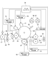
- FIG. 1 is a schematic diagram illustrating an overall configuration of an image forming apparatus according to a first embodiment.
- 1 is a block diagram illustrating a circuit configuration of an image forming apparatus according to a first embodiment.
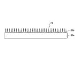
- FIG. 2 is a schematic diagram illustrating a static elimination needle included in the image forming apparatus according to the first embodiment.
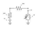
- FIG. 3 is an equivalent circuit diagram including a static elimination bias application circuit in the image forming apparatus according to the first embodiment.
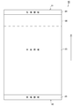
- FIG. 3 is a diagram illustrating a recording paper region used by the image forming apparatus according to the first embodiment. 3 is a timing chart illustrating an operation of the image forming apparatus according to the first embodiment.
- FIG. 6 is a diagram for explaining the movement of a recording sheet in the image forming apparatus according to the first embodiment.
- FIG. 6 is a diagram for explaining the movement of a recording sheet in the image forming apparatus according to the first embodiment.
- FIG. 6 is a diagram for explaining the movement of a recording sheet in the image forming apparatus according to the first embodiment.
- FIG. 6 is an equivalent circuit diagram including a first modification of a static elimination bias application circuit included in the image forming apparatus according to the first embodiment.
- FIG. 6 is an equivalent circuit diagram including a second modification of the static elimination bias application circuit included in the image forming apparatus according to the first embodiment.
- 12 is a timing chart illustrating an operation of the image forming apparatus according to the second embodiment.
- FIG. 1 is a schematic diagram illustrating the overall configuration of the image forming apparatus 1.
- FIG. 2 is a block diagram illustrating a circuit configuration of the image forming apparatus 1.
- the image forming apparatus 1 is an electrophotographic image forming apparatus and uses a contact-type nonmagnetic one-component developing system.
- the image forming apparatus 1 is used as a printer, for example.
- the document reading unit 2 is arranged at the upper part of the image forming apparatus 1, and the paper feeding unit 3 and the recording unit 4 are arranged at the lower part thereof.
- the document reading unit 2 when a document is set on the document tray 11 provided on the document cover 10, the document is transported and read by the document transport mechanism 12 to a position facing the reading device 9, and then the document is discharged. It is discharged to the paper tray 13.
- the document cover 10 When reading a book or the like, the document cover 10 is rotated upward to place a portion to be read such as a book on the platen 14 and the reading device 9 performs a reading operation.
- the read image information of the document is sent to a printer controller 70 described later.
- the paper feeding unit 3 is provided with a paper feeding cassette 15, and a plurality of recording papers of a predetermined size are stacked on a flapper 16 arranged at the lower part of the paper feeding cassette 15.
- a pickup roller 17 is disposed at the end of the paper feed cassette 15, and the flapper 16 is urged upward by a spring member so that the upper surface of the stacked recording paper is pressed against the pickup roller 17. For this reason, when the pickup roller 17 is driven to rotate, the recording paper is fed one by one to the recording paper conveyance path by the frictional action of a friction pad (not shown) attached to the surface of the pickup roller 17 and the recording paper.
- the recording paper conveyance path is indicated by a one-dot chain line.
- the recording paper fed from the paper feeding cassette 15 is detected by the PSS sensor 60 disposed on the paper feeding path to the effect that the recording paper has been transported to a predetermined position. Thereafter, the sheet is conveyed to the recording unit 4 by the pair of registration rollers 18 and 19.
- the recording unit 4 mainly records the photosensitive drum 20, the charger 21, the exposure head 22, the developing unit 23, the transfer roller 24, the cleaning blade 25, the fixing roller 26, and the like in order to record image information on the conveyed recording paper. Is provided.
- the photosensitive drum 20 has a cylindrical shape, and a photoconductive film having a predetermined thickness is provided on the outer peripheral surface as a photosensitive member, and is rotated by a main motor 56.
- a charger 21, an exposure head 22, a developing unit 23, a transfer roller 24, and a cleaning blade 25 are arranged in this order along the rotation direction.
- the charger 21 is a so-called scorotron charger (corona charger) in which a corona wire made of a thin wire such as tungsten is surrounded by a casing, and uniformly charges the surface of the photosensitive drum 20.
- a charging bias application circuit 50 is connected to the charger 21 and a negative charging bias is applied. When the charging bias application circuit 50 applies a charging bias to the charger 21 based on a control signal from the printer controller 70, the surface of the photosensitive drum 20 is uniformly charged to about -750V.
- the exposure head (exposure unit) 22 irradiates the surface of the photosensitive drum 20 with the LED light output from the LED head to form an electrostatic latent image. More specifically, the exposure head 22 irradiates the surface of the photosensitive drum 20 uniformly charged with LED light based on image information input from the printer controller 70 to expose the surface of the photosensitive drum 20. Thus, an electrostatic latent image corresponding to the image information is formed. Further, the surface of the photosensitive drum 20 is neutralized by the exposure, and the surface potential after the exposure becomes about ⁇ 100V.
- the developing unit 23 is provided on the downstream side of the exposure head 22 along the rotation direction of the photosensitive drum 20.
- a detachable toner cartridge 23 a is provided above the developing unit 23, and nonmagnetic one-component toner in the toner cartridge 23 a is supplied into the developing unit 23.
- the developing unit 23 transfers toner onto the electrostatic latent image on the photosensitive drum 20 by the supply roller 27 and the developing roller 28 to form a toner image.
- a developing bias applying circuit 51 is connected to the supply roller 27 and the developing roller 28 in the developing device 23.
- the development bias application circuit 51 applies a bias voltage to each of the supply roller 27 and the development roller 28 based on a control signal output from the printer controller 70.
- a predetermined supply bias for example, ⁇ 350 V
- a predetermined developing bias for example, ⁇ 300 V
- the toner is transferred using the potential difference from the exposed portion while contacting the surface of the photosensitive drum 20.
- the transfer roller 24 is provided in contact with the outer peripheral surface of the photosensitive drum 20 on the downstream side of the developing unit 23 along the rotational direction of the photosensitive drum 20 to form a transfer nip.
- an electronic conductive roller or an ion conductive roller is mainly used.
- a transfer bias applying circuit 52 is connected to the transfer roller 24. When the recording paper is conveyed to the transfer nip portion, the transfer bias applying circuit 52 transfers the transfer bias based on a control signal from the printer controller 70. 24. That is, the transfer roller 24 functions as a transfer unit described in the claims, and the transfer bias application circuit 52 functions as a transfer bias application unit.
- the recording paper conveyed to the transfer nip is sandwiched between the outer peripheral surface of the photosensitive drum 20 and the transfer roller 24 and is charged via the transfer roller 24 by a transfer bias.
- the toner image formed on the surface of the photosensitive drum 20 is transferred onto the recording paper by electrostatic force. Further, since the recording paper is charged, the recording paper after transfer tends to stick to the surface of the photosensitive drum 20.
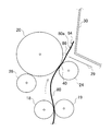
- FIG. 3 is a view showing the static elimination needle 29.
- the static elimination needle 29 has a base end portion 29a extending in the longitudinal direction of the photosensitive drum 20 and the transfer roller 24, and a plurality of needle-like portions 29b protruding in a needle shape from the base end portion 29a.
- the tip of the needle-like portion 29 b is disposed toward the photosensitive drum 20.
- a static elimination bias application circuit 53 is connected to the static elimination needle 29, and the static elimination bias application circuit 53 applies a static elimination bias having a polarity opposite to the above-described transfer bias to the static elimination needle 29 based on a control signal output from the printer controller 70. Apply. As shown in FIG. 4, the static elimination bias application circuit 53 has a variable voltage circuit, and changes the value of the static elimination bias according to the control signal.
- the static elimination needle 29 to which the static elimination bias is applied neutralizes the recording paper passing in front of the static elimination needle 29. That is, the static elimination needle 29 functions as a static elimination member described in the claims, and the static elimination bias application circuit 53 functions as a static elimination bias application means.
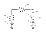
- FIG. 4 is an equivalent circuit diagram including the static elimination bias application circuit 53, and shows the recording paper as a resistor 80R.
- the recording paper has a high resistance value under low temperature and low humidity, but the resistance value decreases due to moisture absorption under high temperature and high humidity.
- the resistor 80R is connected to a resistor 24R corresponding to the transfer roller 24, and the resistor 24R is connected to a transfer bias application circuit 52.
- the recording paper neutralized by the static elimination needle 29 is peeled off from the photosensitive drum 20 and conveyed toward a conveyance guide 30 provided on the downstream side of the static elimination needle 29.
- a conveyance guide 30 provided on the downstream side of the static elimination needle 29.
- the recording sheet is conveyed toward the fixing roller 26 disposed above the conveyance guide 30.
- the recording paper is conveyed along with the rotation of the photosensitive drum 20, so that the peeling claw 31 provided on the downstream side of the static eliminating needle 29 causes the peeling claw 31 of the recording paper. Penetration between the photosensitive drum 20 and the recording paper from the leading end side can be promoted.
- the toner image transferred to the recording paper is sandwiched between the heated fixing roller 26 and the press roller 32, and is heated and pressed to be fixed on the recording paper.
- a heater driving circuit 54 is connected to the fixing roller 26.
- the heater drive circuit 54 causes the heater lamp in the fixing roller 26 to generate heat based on a control signal from the printer controller 70.
- a thermistor is disposed in contact with the surface, and the printer controller 70 controls the heater drive circuit 54 based on the detection signal of the thermistor to set the surface temperature of the fixing roller 26 to a predetermined value. Maintain temperature.
- the fixed recording sheet is nipped between the pair of discharge rollers 33 and 34 and is carried out to the recording sheet discharge tray 35.
- a cleaning blade 25 for collecting toner on the photosensitive drum 20 is provided on the downstream side of the transfer roller 24 with respect to the rotation direction of the photosensitive drum 20.
- the cleaning blade 25 is, for example, a rubber blade, contacts the photosensitive drum 20, and scrapes and collects residual toner on the photosensitive drum 20.
- the main motor 56 rotationally drives the photosensitive drum 20, the supply roller 27, the developing roller 28, and the transfer roller 24 constituting the developing process unit based on a control signal from the printer controller 70.
- the pickup roller 17, the registration roller pair 18 and 19, the fixing roller 26, the press roller 32, and the paper discharge roller pair 33 and 34 constituting the recording paper transport unit discharge the recording paper by the rotational driving force from the sub motor 57. It is designed to rotate in the direction of paper.
- the pickup roller 17 is connected to the sub motor 57 via the paper feed clutch 58.
- the paper feed clutch 58 intermittently drives the driving force transmitted from the sub motor 57 to the pickup roller 17 based on a control signal from the printer controller 70.
- the registration roller pairs 18 and 19 are connected to the sub motor 57 via a registration clutch 59.
- the registration clutch 59 interrupts the driving force transmitted from the sub motor 57 to the registration roller pairs 18 and 19 based on a control signal from the printer controller 70.
- the image forming apparatus 1 includes a temperature sensor 61 that measures the temperature in the image forming apparatus 1 and a humidity sensor 62 that measures humidity. Output values of the temperature sensor 61 and the humidity sensor 62 are output to the printer controller 70.
- the printer controller 70 can perform control based on environmental conditions including temperature and humidity that are affected when an image is formed on recording paper.
- the temperature sensor 61 and the humidity sensor 62 function as detection means for detecting the environmental conditions described in the claims.
- the printer controller 70 controls the driving of the main motor 56 and the sub motor 57 as described above, and also includes the exposure head 22, the charging bias application circuit 50, the development bias application circuit 51, the transfer bias application circuit 52, the neutralization bias application circuit 53, and the like.
- the heater driving circuit 54 is controlled to execute the image forming process.
- the printer controller 70 includes a microprocessor that performs calculations, a ROM that stores programs for causing the microprocessor to execute each process, a RAM that temporarily stores various data such as calculation results, and a backup in which data is backed up. It is comprised by RAM etc.
- the printer controller 70 executes a program stored in the ROM, thereby comprehensively controlling the hardware configuring the image forming apparatus 1 described above, and performs processing for forming an image on recording paper.
- FIG. 5 shows a recording sheet 80 on which printing is performed by the image forming apparatus 1.
- the front end is referred to as a front end 81
- the rear end is referred to as a rear end 82.
- the recording paper 80 can be divided into a central region 83 on which an image is printed, a leading end region 84 on the leading end 81 side from the central region 83, and a trailing end region 85 on the trailing end 82 side from the central region 83.
- the central area 83 is a transfer area where the toner image is transferred.
- the leading end region 84 and the trailing end region 85 are blank regions set as regions where the toner image is not transferred.
- the front end region 84 is a region about 3 mm from the front end 81
- the rear end region 85 is a region about 3 mm from the rear end 82.
- the region 86 on the distal end side in the central region 83 is a region through which the neutralization needle 29 passes after the distal end side of the central region 83 passes through the neutralization needle 29 until the distal end 81 contacts the conveyance guide 30. .
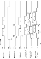
- FIG. 6 shows a timing chart in the case where the image forming apparatus 1 performs the printing process continuously on two recording sheets.
- the vertical axis represents the absolute value of the value applied from the transfer bias application circuit 52 to the transfer roller 24.
- the vertical axis indicates the absolute value of the value applied from the static elimination bias application circuit 53 to the static elimination needle 29. Note that the numbers “1” and “2” shown in FIG. 6 indicate the one corresponding to the first sheet and the second corresponding sheet of the recording paper 80.
- a print signal is input to the printer controller 70 (t0), and when the temperature of the fixing roller 26 reaches a predetermined value, a drive signal is output to the main motor 56. Thereby, the rotation of the main motor 56 is started (t1).
- the photosensitive drum 20 starts rotating by the driving force of the main motor 56, and the charging process of the photosensitive drum 20 is started. Further, cleaning of the transfer roller 24 is started at time t1. Further, in order to execute a cleaning process for returning the reversely charged toner on the transfer roller 24 onto the photosensitive drum 20, a transfer bias of about +5.0 ⁇ A is applied to the transfer roller 24 by the transfer bias applying circuit 52 (t2). ).
- the paper feeding clutch 58 is engaged (turned on) (t3), the first recording paper is supplied from the recording paper cassette 15 to the paper feeding path by the pickup roller 17.
- the leading edge 81 of the recording paper 80 is detected by the PSS sensor 60 (t4), the leading edge 81 of the recording paper 80 hits the registration roller pair 18 and 19 in a state where the rotation is stopped, and the orientation of the recording paper 80 is appropriate. Corrected to position.
- the registration clutch 59 is engaged (turned on), whereby the registration roller pair 18 and 19 starts to rotate, and the recording paper 80 is conveyed to the transfer position.
- the registration clutch 59 is engaged, the exposure head 22 is turned on, and the exposure process for the photosensitive drum 20 is started. Subsequently, development processing is performed on the photosensitive drum 20, a toner image is formed on the outer peripheral surface of the photosensitive drum 20, and the region where the toner image is formed rotates toward the transfer position.
- the leading end 81 of the first recording sheet 80 reaches the transfer nip (t5). Then, the leading end 81 of the recording paper 80 is sandwiched between the photosensitive drum 20 and the transfer roller 24 and passes through the transfer roller 24. While the leading end region 84 of the recording paper 80 passes through the transfer roller 24 (X1), a transfer bias of about +5.0 ⁇ A is continuously applied to the transfer roller 24 by the transfer bias applying circuit 52. As a result, the leading end region 84 of the recording paper 80 in contact with the transfer roller 24 is charged.
- the transfer bias raised to the transfer bias (about +10 ⁇ A) set based on the environmental conditions is applied from the transfer bias application circuit 52 to the transfer roller 24 (t6).
- a transfer bias set based on environmental conditions is applied to the transfer roller 24.
- the transfer bias applied to the transfer roller 24 is pulled up to a value set based on environmental conditions, the central region 83 of the recording paper 80 is more strongly charged than the leading end region 84.
- the toner image is transferred to the recording paper 80 by electrostatic force.
- the values set based on the environmental conditions are set by the printer controller 70 based on the temperature and humidity input from the temperature sensor 61 and the humidity sensor 62 and the transfer bias table.
- the transfer bias table is set so that the transfer bias increases as the environmental conditions become higher.
- the transfer bias lowered to about +5.0 ⁇ A is applied to the transfer roller 24 again (t7). While the rear end region 85 passes through the transfer roller 24 (X3), a smaller transfer bias is applied to the transfer roller 24 while the central region 84 passes through the transfer roller 24. As a result, the charge amount of the rear end region 85 of the recording paper 80 in contact with the transfer roller 24 is smaller than the charge amount of the central region 83. Therefore, it becomes easy to peel from the photosensitive drum 20.
- FIGS. 7 to 9 are a series of diagrams for explaining the movement of the recording paper in the image forming apparatus according to the first embodiment.
- the neutralization bias of about ⁇ 0.5 kV is applied until the leading end 81 of the first recording sheet 80 reaches the neutralization needle 29.
- the charge is applied from the charge removal bias application circuit 53 to the charge removal needle 29.
- a portion 80 a that has passed through the transfer nip portion 40 in the first recording paper 80 is charged and tends to stick to the photosensitive drum 20. In this state, the leading end 81 of the recording paper 80 reaches before the static elimination needle 29 (FIG. 7).
- the static elimination bias is raised from -0.5 kV to -2.5 kV (d2). Then, while the leading end region 84 of the first recording paper 80 passes in front of the static elimination needle 29 (P1), a static elimination bias of about ⁇ 2.5 kV is applied from the static elimination bias application circuit 53 to the static elimination needle 29. . As a result, the leading end region 84 of the recording paper 80 is neutralized, so the electrostatic force between the leading end region 84 of the recording paper 80 and the photosensitive drum 20 is reduced, and the leading end region 84 of the recording paper 80 from the photosensitive drum 20 is reduced. Peels off.
- the front end region 84 of the recording paper 80 is peeled off from the photosensitive drum 20, and is conveyed obliquely upward, abuts on a conveyance guide 30 having a surface arranged substantially vertically, and is conveyed while being supported by the conveyance guide 30. Is done.
- the leading end region 84 is peeled from the photosensitive drum 20
- the portion 80a of the recording paper 80 that has passed through the transfer nip portion 40 is in an unstable state until the leading end 81 contacts the conveyance guide 30. For this reason, it becomes easy to be attracted to the static elimination needle 29.
- the static elimination bias is lowered from -2.5 kV to -1.0 kV (d3).
- the electrostatic force that attracts the recording paper 80 in the static elimination needle 29 is reduced, so that the recording paper 80 can be prevented from approaching the static elimination needle 29 more than necessary. That is, it is possible to prevent a closed circuit that connects the transfer roller 24, the recording paper 80, and the static elimination needle 29 from being formed.
- the value of the static elimination bias is maintained at ⁇ 1.0 kV until the timing (d4) when the leading end 81 of the recording paper 80 contacts the conveyance guide 30 (P2; FIG. 8). After the leading end 81 of the recording paper 80 comes into contact with the transport guide 30, the recording paper 80 is supported by the transport guide 30 and is transported upward in a stable posture (FIG. 9). For this reason, the above closed circuit is not formed.
- the static elimination bias is raised from -1.0 kV to a value according to the environmental conditions.
- Values corresponding to the environmental conditions are set by the printer controller 70 based on the temperature and humidity input from the temperature sensor 61 and the humidity sensor 62 and the static elimination bias table. The higher the temperature and the higher the humidity, the more difficult the recording paper 80 is peeled from the photosensitive drum 20. Therefore, the static elimination bias table is set so that the static elimination bias increases as the environmental conditions increase in temperature and humidity. .
- the static elimination bias is raised to -2.5 kV (d5). While the rear end region 85 passes in front of the static elimination needle 29 (P4), a static elimination bias of about ⁇ 2.5 kV is applied from the static elimination bias application circuit 53 to the static elimination needle 29, and the recording paper 80 is easily peeled off. can do.
- the rear end 82 of the first recording paper 80 passes through the static elimination needle 29 (d6), and until the leading end 81 of the second recording paper 80 reaches the static elimination needle 29, it is about ⁇ 0.5 kV.
- the static elimination bias is applied from the static elimination bias application circuit 53 to the static elimination needle 29.
- the printer controller 70 uses the timer, the output of the PSS sensor 60, and the like to determine the timing when each position of the recording paper 80 reaches the transfer roller 24 and the timing when it passes in front of the charge eliminating needle 29, and performs the above control. Do.
- the printer controller 70 has a neutralizing bias applied to the recording paper 80 after the leading end region 84 of the recording paper 80 passes through the static eliminating needle 29 until the leading end 81 of the recording paper 80 contacts the conveyance guide 30.
- the static elimination bias application circuit 53 is controlled so that the tip region 84 becomes smaller than the static elimination bias applied while passing through the static elimination needle 29.
- This can be made smaller than the potential difference while the leading end region 84 of the paper 80 passes through the static elimination needle 29. Therefore, it is possible to suppress the portion of the recording paper 80 whose posture is unstable from being attracted to the static elimination needle 29, and to prevent the formation of a closed circuit that connects the transfer roller 24, the recording paper 80, and the static elimination needle 29. That is, the charge supplied to the recording paper 80 via the transfer roller 24 can be prevented from flowing to the static elimination needle 29. Therefore, it is possible to suppress a decrease in the effective charge amount for transferring the toner to the recording paper, and to prevent transfer defects such as white spots.
- the portion 80 a that has passed through the transfer nip portion 40 of the recording paper 80 is supported by the conveyance guide 30, so that the posture is stabilized.
- the static elimination bias set based on the environmental conditions is applied to the static elimination needle 29, the static electricity is removed from the recording paper according to the environmental conditions so that the recording paper 80 is easily peeled off from the photosensitive drum 20. can do.
- the printer controller 70 determines the value of the neutralization bias applied between the time when the leading end region 84 of the recording paper 80 passes through the static elimination needle 29 and the time when the leading end 81 of the recording paper 80 contacts the conveyance guide 30.
- the static elimination bias application circuit may be controlled so that becomes zero.
- FIG. 10 is an equivalent circuit diagram including a first modification of the static elimination bias application circuit.
- the static elimination bias application circuit 53A includes a high voltage power source 63 for applying a static elimination bias of ⁇ 2.5 kV while the leading end region 84 of the recording paper 80 passes in front of the static elimination needle 29, and the leading end of the recording paper 80.
- a switch 64 for disconnecting the connection between the high-voltage power supply 63 and the charge removal needle 29 is provided between the region 84 passing through the charge removal needle 29 and the leading edge of the recording paper 80 coming into contact with the conveyance guide 30.
- the potential difference can be made smaller than the potential difference while the leading end region 84 of the recording paper 80 passes through the static elimination needle 29. Therefore, transfer defects such as white spots can be prevented.
- the printer controller 70 applies a neutralizing bias having a polarity opposite to the transfer bias to the neutralizing needle 29 while the leading end region 84 of the recording paper 80 passes through the neutralizing needle 29.
- the neutralization bias is applied so that a bias having the same polarity as the transfer bias is applied to the neutralization needle 29 after the leading end region 84 passes through the neutralization needle 29 and until the leading end 81 of the recording paper 80 contacts the conveyance guide 30.
- the application circuit may be controlled.
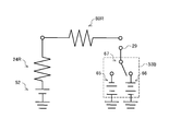
- FIG. 11 is an equivalent circuit diagram including the static elimination bias application circuit 53B according to the second modification.
- the static elimination bias application circuit 53B includes a high voltage power supply 65 for applying a static elimination bias having a polarity opposite to the transfer bias, a high voltage power supply 66 for applying a static elimination bias having the same polarity as the transfer bias, and a switch 67. .
- the switch 67 switches between the case where the static elimination needle 29 is connected to the high voltage power supply 65 and the case where it is connected to the high voltage power supply 66.
- the potential difference can be made smaller than the potential difference while the leading end region 84 of the recording paper 80 passes through the static elimination needle 29. Therefore, as described above, transfer defects such as white spots can be prevented.
- the image forming apparatus 1 that suppresses the reduction in the effective charge amount for transferring the toner onto the recording paper by controlling the neutralizing bias has been described.
- the image forming apparatus according to the second embodiment suppresses the decrease in the effective charge amount by controlling the transfer bias.
- FIG. 12 shows a timing chart in the case where the printing process is continuously performed on two recording sheets in the image forming apparatus. Note that differences from the image forming apparatus 1 according to the first embodiment will be mainly described, and description of similar points will be omitted.
- a transfer bias of about +5.0 ⁇ A is applied to execute a cleaning process for returning the reversely charged toner on the transfer roller 24 onto the photosensitive drum 20. It is applied to the transfer roller 24 by the transfer bias applying circuit 52 (t2). After the registration clutch 59 is engaged, a transfer bias of about +5.0 ⁇ A is continuously applied to the transfer roller 24 by the transfer bias application circuit 52 while the leading end region 84 of the recording paper 80 passes through the transfer roller 24.
- the transfer bias raised to a value set according to the environmental conditions is applied from the transfer bias application circuit 52 to the transfer roller 24. (T6). Then, at the timing when the leading end side of the central region 83 reaches the static elimination needle 29, the transfer bias is pulled up from a value set according to environmental conditions to about +15 ⁇ A (d3).
- the transfer bias application circuit 52 is replenished to the recording paper 80. Thereafter, at the timing when the leading edge 81 of the recording paper 80 comes into contact with the conveyance guide 30, the transfer bias is lowered again from about +15 ⁇ A to a value set according to the environmental conditions (d4).
- the transfer bias lowered to about +5.0 ⁇ A is applied to the transfer roller 24 again (t7).
- the rear end 82 of the first recording sheet 80 passes through the transfer nip 40 (t8) and the leading end 81 of the second recording sheet 80 reaches the transfer nip 40 (t9) (Y).
- a transfer bias of about +5.0 ⁇ A is continuously applied from the transfer bias application circuit 52 to the transfer roller 24.
- the static elimination bias is raised from ⁇ 0.5 kV to ⁇ 2.5 kV at the timing when the leading end 81 of the recording paper 80 reaches the static elimination needle 29 (d2). Then, while the leading end region 84 of the first recording paper 80 passes through the static elimination needle 29 (P1), a static elimination bias of about ⁇ 2.5 kV is applied from the static elimination bias application circuit 53 to the static elimination needle 29. Then, at the timing when the front end side of the central region 83 reaches the static elimination needle 29, the static elimination bias is lowered to a value set according to the environmental conditions (d3).
- the static elimination bias is raised to -2.5 kV (d5).
- the rear end 82 of the first recording paper 80 passes through the static elimination needle 29 (d6), and until the leading end 81 of the second recording paper 80 reaches the static elimination needle 29, it is about ⁇ 0.5 kV.
- the static elimination bias is applied from the static elimination bias application circuit 53 to the static elimination needle 29. Subsequently, the same control is performed for the second recording sheet 80.
- the printer controller 70 allows the front end 81 of the recording paper 80 to contact the conveyance guide 30 after the front end region 84 of the recording paper 80 passes through the static elimination needle 29.
- the transfer bias application circuit 52 is controlled so that the transfer bias applied until this time becomes larger than the transfer bias applied after the leading end 81 of the recording paper 80 contacts the conveyance guide 30.
- the amount of charge supplied from the transfer roller 24 to the recording paper 80 after the leading edge region 84 of the recording paper 80 passes through the static elimination needle 29 until the leading edge 81 of the recording paper 80 contacts the conveyance guide 30 is reduced.
- the charge amount after the leading end 81 of the recording paper 80 contacts the conveyance guide 30 can be increased. Accordingly, even if the portion of the recording paper 80 in which the posture is unstable is attracted to the static elimination needle 29 to form the closed circuit, and the electric charge flows from the recording paper 80 to the static elimination needle 29, the electric charge is applied to the recording paper 80. Since the toner is replenished, it is possible to suppress a decrease in the effective charge amount for transferring the toner to the recording paper. Therefore, transfer defects such as white spots can be prevented.
- the printer controller 70 uses a constant voltage until the leading end region 84 of the recording paper 80 passes through the static elimination needle 29 and the leading end 81 of the recording paper 80 contacts the conveyance guide 30.
- the transfer bias application circuit 52 may be controlled by control, and the transfer bias application circuit 52 may be controlled by constant current control after the leading edge 82 of the recording paper 80 contacts the conveyance guide 30.
- the transfer bias is set based on the environmental conditions that affect the transfer, so that the transfer can be performed well and the image quality is improved. Can be made.
- both the temperature sensor 61 and the humidity sensor 62 are provided in order to measure the environmental conditions.
- the structure provided only with this may be sufficient.
- the property that the transfer roller 24 changes its resistance value according to changes in temperature and humidity may be used.
- An ion conductive roller is an example of a transfer roller having such remarkable properties.
- a transfer bias set based on the current value flowing through the transfer roller 24 when a test voltage is applied to the transfer roller 24 is applied to the transfer roller 24.
- the neutralization bias may be controlled as in the first embodiment, and the transfer bias may be controlled as in the second embodiment. Also in this case, it is possible to suppress a decrease in the effective charge amount for transferring the toner to the recording paper.
- the image forming apparatus 1 is used as a printer.
- the image forming apparatus 1 may be used as a multifunction machine having functions of copying, facsimile, and printer.
Landscapes
- Physics & Mathematics (AREA)
- General Physics & Mathematics (AREA)
- Electrostatic Charge, Transfer And Separation In Electrography (AREA)
- Control Or Security For Electrophotography (AREA)
Abstract
Description
(第1実施形態)
上記第1実施形態として、除電バイアスを制御することにより、トナーを記録紙に転写するための実効電荷量が減少することを抑制する画像形成装置1について説明した。第2実施形態に係る画像形成装置は、転写バイアスを制御することにより、実効電荷量が減少することを抑制する
20 感光体ドラム
21 帯電器
22 露光ヘッド
23 現像器
24 転写ローラ
25 クリーニングブレード
26 定着ローラ
29 除電針
30 搬送ガイド
52 転写バイアス印加回路
53 除電バイアス印加回路
61 温度センサ
62 湿度センサ
70 プリンタコントローラ
80 記録紙
81 先端
84 先端領域
Claims (10)
- 電子写真方式を用いて画像を記録紙に形成する画像形成装置において、
トナー像が形成される外周面を有する感光体ドラムと、
前記感光体ドラムと当接して設けられ、前記感光体ドラムの外周面に形成された前記トナー像を記録紙に転写する転写手段と、
前記転写手段に転写バイアスを印加する転写バイアス印加手段と、
前記転写手段より記録紙の搬送方向の下流側に配置され、前記トナー像が転写された記録紙を除電する除電部材と、
前記除電部材に除電バイアスを印加する除電バイアス印加手段と、
前記除電部材より下流側に配置され、前記除電部材を通過した記録紙の搬送をガイドする搬送ガイドと、
前記記録紙の先端領域が前記除電部材を通過してから前記記録紙の先端が前記搬送ガイドに接するまでの間における前記除電部材と前記記録紙との間の電位差が、前記記録紙の先端領域が前記除電部材を通過している間における電位差より小さくなるように、前記除電バイアス印加手段を制御するコントローラと、
を備えることを特徴とする画像形成装置。 - 前記除電バイアスは、前記転写バイアスと逆極性のバイアスであり、
前記コントローラは、前記記録紙の先端領域が前記除電部材を通過してから前記記録紙の先端が前記搬送ガイドに接するまでの間に印加される前記除電バイアスの絶対値が、前記記録紙の先端領域が前記除電部材を通過している間に印加される除電バイアスの絶対値より小さくなるように、前記除電バイアス印加手段を制御することを特徴とする請求項1に記載の画像形成装置。 - 前記コントローラは、前記記録紙の先端領域が前記除電部材を通過している間に、前記転写バイアスと逆極性の前記除電バイアスを前記除電部材に印加し、前記記録紙の先端領域が前記除電部材を通過してから前記記録紙の先端が前記搬送ガイドに接するまでの間に、前記除電部材に印加する除電バイアスの値が0となるように、前記除電バイアス印加手段を制御することを特徴とする請求項1に記載の画像形成装置。
- 前記コントローラは、前記記録紙の先端領域が前記除電部材を通過している間に、前記転写バイアスと逆極性の前記除電バイアスを前記除電部材に印加し、前記記録紙の先端領域が前記除電部材を通過してから前記記録紙の先端が前記搬送ガイドに接するまでの間に、前記転写バイアスと同極性のバイアスを前記除電部材に印加するように、前記除電バイアス印加手段を制御することを特徴とする請求項1に記載の画像形成装置。
- 温度と湿度とのうち少なくとも一方を含む環境条件を検知する検知手段を備え、
前記コントローラは、前記検知手段によって検知された環境条件に基づいて設定された前記除電バイアスが、前記記録紙の先端が前記搬送ガイドに接した後に前記除電部材へ印加されるように、前記除電バイアス印加手段を制御することを特徴とする請求項1~4のいずれか1項に記載の画像形成装置。 - 前記コントローラは、前記転写手段に試験電圧を印加したときに前記転写手段に流れる電流値に基づいて設定された前記除電バイアスが、前記記録紙の先端が前記搬送ガイドに接した後に前記除電部材へ印加されるように、前記除電バイアス印加手段を制御することを特徴とする請求項1~4のいずれか1項に記載の画像形成装置。
- 電子写真方式を用いて画像を記録紙に形成する画像形成装置において、
トナー像が形成される外周面を有する感光体ドラムと、
前記感光体ドラムと当接して設けられ、前記感光体ドラムの外周面に形成された前記トナー像を記録紙に転写する転写手段と、
前記転写手段に転写バイアスを印加する転写バイアス印加手段と、
前記転写手段より記録紙の搬送方向の下流側に配置され、前記トナー像が転写された記録紙を除電する除電部材と、
前記除電部材に除電バイアスを印加する除電バイアス印加手段と、
前記除電部材より下流側に設けられ、前記除電部材を通過した記録紙の搬送をガイドする搬送ガイドと、
前記記録紙の先端領域が前記除電部材を通過してから前記記録紙の先端が前記搬送ガイドに接するまでの間に印加される転写バイアスの絶対値が、前記記録紙の先端が前記搬送ガイドに接した後に印加される転写バイアスの絶対値より大きくなるように、前記転写バイアス印加手段を制御するコントローラと、
を備えることを特徴とする画像形成装置。 - 電子写真方式を用いて画像を記録紙に形成する画像形成装置において、
トナー像が形成される外周面を有する感光体ドラムと、
前記感光体ドラムと当接して設けられ、前記感光体ドラムの外周面に形成された前記トナー像を記録紙に転写する転写手段と、
前記転写手段に転写バイアスを印加する転写バイアス印加手段と、
前記転写手段より記録紙の搬送方向の下流側に配置され、前記トナー像が転写された記録紙を除電する除電部材と、
前記除電部材に除電バイアスを印加する除電バイアス印加手段と、
前記除電部材より下流側に設けられ、前記除電部材を通過した記録紙の搬送をガイドする搬送ガイドと、
前記記録紙の先端領域が前記除電部材を通過してから前記記録紙の先端が前記搬送ガイドに接するまでの間は、定電圧制御により前記転写バイアス印加手段を制御し、前記記録紙の先端が前記搬送ガイドに接した後は、定電流制御により前記転写バイアス印加手段を制御するコントローラと、
を備えることを特徴とする画像形成装置。 - 温度と湿度とのうち少なくとも一方を含む環境条件を検知する検知手段を備え、
前記コントローラは、前記検知手段によって検知された環境条件に基づいて設定された転写バイアスが、前記記録紙の先端が前記搬送ガイドに接した後に前記転写手段へ印加されるように、前記転写バイアス印加手段を制御することを特徴とする請求項7又は8に記載の画像形成装置。 - 前記コントローラは、前記転写手段に試験電圧を印加したときに前記転写手段に流れる電流値に基づいて設定された転写バイアスが、前記記録紙の先端が前記搬送ガイドに接した後に前記転写手段へ印加されるように、前記転写バイアス印加手段を制御することを特徴とする請求項7又は8に記載の画像形成装置。
Priority Applications (3)
| Application Number | Priority Date | Filing Date | Title |
|---|---|---|---|
| DE112010001713T DE112010001713T5 (de) | 2009-04-23 | 2010-04-15 | Bilderzeugende Vorrichtung |
| CN201080006752.9A CN102308261B (zh) | 2009-04-23 | 2010-04-15 | 图像形成装置 |
| US13/259,309 US8712262B2 (en) | 2009-04-23 | 2010-04-15 | Image forming apparatus with static elimination |
Applications Claiming Priority (2)
| Application Number | Priority Date | Filing Date | Title |
|---|---|---|---|
| JP2009-105719 | 2009-04-23 | ||
| JP2009105719A JP4992932B2 (ja) | 2009-04-23 | 2009-04-23 | 画像形成装置 |
Publications (1)
| Publication Number | Publication Date |
|---|---|
| WO2010122745A1 true WO2010122745A1 (ja) | 2010-10-28 |
Family
ID=43010873
Family Applications (1)
| Application Number | Title | Priority Date | Filing Date |
|---|---|---|---|
| PCT/JP2010/002729 Ceased WO2010122745A1 (ja) | 2009-04-23 | 2010-04-15 | 画像形成装置 |
Country Status (5)
| Country | Link |
|---|---|
| US (1) | US8712262B2 (ja) |
| JP (1) | JP4992932B2 (ja) |
| CN (1) | CN102308261B (ja) |
| DE (1) | DE112010001713T5 (ja) |
| WO (1) | WO2010122745A1 (ja) |
Families Citing this family (8)
| Publication number | Priority date | Publication date | Assignee | Title |
|---|---|---|---|---|
| US20150249792A1 (en) * | 2012-08-17 | 2015-09-03 | Nikon Corporation | Image processing device, imaging device, and program |
| JP6163362B2 (ja) | 2013-06-11 | 2017-07-12 | 京セラドキュメントソリューションズ株式会社 | 画像形成装置 |
| JP6381423B2 (ja) * | 2014-11-25 | 2018-08-29 | キヤノン株式会社 | 画像形成装置 |
| US9778612B2 (en) * | 2015-04-30 | 2017-10-03 | Ricoh Company, Ltd. | Image forming apparatus including charge removing needle and light irradiator |
| JP6641617B2 (ja) * | 2015-10-15 | 2020-02-05 | 株式会社リコー | 画像形成装置 |
| EP3384349B1 (en) * | 2015-11-30 | 2020-12-30 | Lexmark International, Inc. | Replaceable unit for an image forming device having magnets of varying angular offset for toner level sensing |
| JP7206714B2 (ja) * | 2018-09-06 | 2023-01-18 | 富士フイルムビジネスイノベーション株式会社 | 転写装置および画像形成装置 |
| JP7409096B2 (ja) * | 2020-01-10 | 2024-01-09 | 富士フイルムビジネスイノベーション株式会社 | 除電装置及びこれを用いた媒体処理装置 |
Citations (8)
| Publication number | Priority date | Publication date | Assignee | Title |
|---|---|---|---|---|
| JPH10340010A (ja) * | 1996-06-21 | 1998-12-22 | Konica Corp | 画像形成装置 |
| JP2003280410A (ja) * | 2002-03-22 | 2003-10-02 | Canon Inc | 画像形成装置 |
| JP2006010882A (ja) * | 2004-06-23 | 2006-01-12 | Ricoh Co Ltd | カラー画像形成装置 |
| JP2006259235A (ja) * | 2005-03-17 | 2006-09-28 | Ricoh Co Ltd | 画像形成装置 |
| JP2007171425A (ja) * | 2005-12-20 | 2007-07-05 | Canon Inc | 画像形成装置 |
| JP2007333829A (ja) * | 2006-06-13 | 2007-12-27 | Konica Minolta Business Technologies Inc | トナー供給ローラ、現像装置および画像形成装置 |
| JP2008185664A (ja) * | 2007-01-29 | 2008-08-14 | Kyocera Mita Corp | 画像形成装置 |
| JP2008241862A (ja) * | 2007-03-26 | 2008-10-09 | Seiko Epson Corp | 画像形成装置および画像形成方法 |
Family Cites Families (4)
| Publication number | Priority date | Publication date | Assignee | Title |
|---|---|---|---|---|
| US5799226A (en) * | 1996-06-21 | 1998-08-25 | Konica Corporation | Electrostatic image forming apparatus with transfer controls for different imaging modes |
| JP2002365923A (ja) | 2001-06-04 | 2002-12-20 | Ricoh Co Ltd | 画像形成装置及び除電バイアス制御方法 |
| JP5220288B2 (ja) * | 2006-07-26 | 2013-06-26 | 京セラドキュメントソリューションズ株式会社 | 画像形成装置 |
| JP4294675B2 (ja) * | 2006-10-23 | 2009-07-15 | シャープ株式会社 | 画像形成装置及び画像形成方法、転写装置 |
-
2009
- 2009-04-23 JP JP2009105719A patent/JP4992932B2/ja active Active
-
2010
- 2010-04-15 CN CN201080006752.9A patent/CN102308261B/zh not_active Expired - Fee Related
- 2010-04-15 DE DE112010001713T patent/DE112010001713T5/de not_active Ceased
- 2010-04-15 US US13/259,309 patent/US8712262B2/en not_active Expired - Fee Related
- 2010-04-15 WO PCT/JP2010/002729 patent/WO2010122745A1/ja not_active Ceased
Patent Citations (8)
| Publication number | Priority date | Publication date | Assignee | Title |
|---|---|---|---|---|
| JPH10340010A (ja) * | 1996-06-21 | 1998-12-22 | Konica Corp | 画像形成装置 |
| JP2003280410A (ja) * | 2002-03-22 | 2003-10-02 | Canon Inc | 画像形成装置 |
| JP2006010882A (ja) * | 2004-06-23 | 2006-01-12 | Ricoh Co Ltd | カラー画像形成装置 |
| JP2006259235A (ja) * | 2005-03-17 | 2006-09-28 | Ricoh Co Ltd | 画像形成装置 |
| JP2007171425A (ja) * | 2005-12-20 | 2007-07-05 | Canon Inc | 画像形成装置 |
| JP2007333829A (ja) * | 2006-06-13 | 2007-12-27 | Konica Minolta Business Technologies Inc | トナー供給ローラ、現像装置および画像形成装置 |
| JP2008185664A (ja) * | 2007-01-29 | 2008-08-14 | Kyocera Mita Corp | 画像形成装置 |
| JP2008241862A (ja) * | 2007-03-26 | 2008-10-09 | Seiko Epson Corp | 画像形成装置および画像形成方法 |
Also Published As
| Publication number | Publication date |
|---|---|
| JP4992932B2 (ja) | 2012-08-08 |
| US8712262B2 (en) | 2014-04-29 |
| CN102308261A (zh) | 2012-01-04 |
| CN102308261B (zh) | 2014-08-13 |
| JP2010256574A (ja) | 2010-11-11 |
| DE112010001713T5 (de) | 2012-11-22 |
| US20120014705A1 (en) | 2012-01-19 |
Similar Documents
| Publication | Publication Date | Title |
|---|---|---|
| JP4992932B2 (ja) | 画像形成装置 | |
| JP2016006471A (ja) | 画像形成装置 | |
| JP2004309569A (ja) | 定着装置および画像形成装置 | |
| JP4047193B2 (ja) | 画像形成装置 | |
| JP6163362B2 (ja) | 画像形成装置 | |
| JP5986962B2 (ja) | 画像形成装置 | |
| US20140044445A1 (en) | Image forming apparatus | |
| JP6252839B2 (ja) | 画像形成装置 | |
| JP4037508B2 (ja) | 画像形成装置 | |
| JP2002296854A (ja) | 画像形成装置 | |
| JP5214093B2 (ja) | 画像形成装置 | |
| JP6490529B2 (ja) | 画像形成装置 | |
| JP5589723B2 (ja) | 画像形成装置 | |
| JP2010197466A (ja) | 画像形成装置 | |
| JP2012150174A (ja) | 画像形成装置 | |
| JP2010210907A (ja) | 画像形成装置 | |
| JP2006072208A (ja) | 画像形成装置 | |
| JP4931562B2 (ja) | 画像形成装置における剥離部材の駆動制御方法及び画像形成装置 | |
| JP5044170B2 (ja) | 画像形成装置 | |
| JPH09114337A (ja) | 画像形成装置 | |
| JP4834533B2 (ja) | シート搬送装置とこれを備えた画像形成装置 | |
| JP2000227746A (ja) | 電子写真装置 | |
| JP2001228727A (ja) | 画像形成装置 | |
| JPH10186902A (ja) | 画像記録装置 | |
| JPH11249389A (ja) | 画像形成装置 |
Legal Events
| Date | Code | Title | Description |
|---|---|---|---|
| WWE | Wipo information: entry into national phase |
Ref document number: 201080006752.9 Country of ref document: CN |
|
| 121 | Ep: the epo has been informed by wipo that ep was designated in this application |
Ref document number: 10766807 Country of ref document: EP Kind code of ref document: A1 |
|
| WWE | Wipo information: entry into national phase |
Ref document number: 13259309 Country of ref document: US |
|
| WWE | Wipo information: entry into national phase |
Ref document number: 1120100017131 Country of ref document: DE Ref document number: 112010001713 Country of ref document: DE |
|
| 122 | Ep: pct application non-entry in european phase |
Ref document number: 10766807 Country of ref document: EP Kind code of ref document: A1 |