WO2010119735A1 - 偏光分離素子およびその製造方法 - Google Patents
偏光分離素子およびその製造方法 Download PDFInfo
- Publication number
- WO2010119735A1 WO2010119735A1 PCT/JP2010/053671 JP2010053671W WO2010119735A1 WO 2010119735 A1 WO2010119735 A1 WO 2010119735A1 JP 2010053671 W JP2010053671 W JP 2010053671W WO 2010119735 A1 WO2010119735 A1 WO 2010119735A1
- Authority
- WO
- WIPO (PCT)
- Prior art keywords
- liquid crystal
- polymer liquid
- groove
- separation element
- polarization separation
- Prior art date
- Legal status (The legal status is an assumption and is not a legal conclusion. Google has not performed a legal analysis and makes no representation as to the accuracy of the status listed.)
- Ceased
Links
Images


Classifications
-
- G—PHYSICS
- G02—OPTICS
- G02B—OPTICAL ELEMENTS, SYSTEMS OR APPARATUS
- G02B27/00—Optical systems or apparatus not provided for by any of the groups G02B1/00 - G02B26/00, G02B30/00
- G02B27/28—Optical systems or apparatus not provided for by any of the groups G02B1/00 - G02B26/00, G02B30/00 for polarising
- G02B27/283—Optical systems or apparatus not provided for by any of the groups G02B1/00 - G02B26/00, G02B30/00 for polarising used for beam splitting or combining
- G02B27/285—Optical systems or apparatus not provided for by any of the groups G02B1/00 - G02B26/00, G02B30/00 for polarising used for beam splitting or combining comprising arrays of elements, e.g. microprisms
-
- G—PHYSICS
- G02—OPTICS
- G02B—OPTICAL ELEMENTS, SYSTEMS OR APPARATUS
- G02B5/00—Optical elements other than lenses
- G02B5/30—Polarising elements
- G02B5/3016—Polarising elements involving passive liquid crystal elements
Definitions
- the present invention relates to a separation element and a manufacturing method thereof.
- a polyimide resin is applied to two transparent substrates and thermally cured, and then an alignment process is performed by buffing to form a liquid crystal alignment film.
- an alignment process is performed by buffing to form a liquid crystal alignment film.
- the temperature is raised to a temperature at which the polymerizable liquid crystal is in an isotropic state and uncured
- a polymer liquid crystal thin film having a predetermined shape of the grating was produced by crosslinking the polymerizable liquid crystal, and a diffraction grating having optical anisotropy was formed.
- this method has a problem that it is difficult to stably control the alignment state of the polymerizable liquid crystal by the formed alignment film, and a cleaning step is essential after buffing.
- An object of the present invention is to solve the above-described problems of the prior art and to provide a separation element using a polymer liquid crystal thin film and a method for manufacturing the same.
- the polarization separation element of the present invention is a polarization separation element in which a stripe structure composed of a uniaxial polymer liquid crystal is arranged.
- the stripe structure composed of a uniaxial polymer liquid crystal is formed in an isotropic medium, and the polymer liquid crystal Is characterized in that the optical axis coincides with the longitudinal direction of the stripe structure.
- the first method of manufacturing the polarization separation element according to the present invention is a high manufacturing method in which a groove having a predetermined shape formed in a medium is filled with a polymerizable liquid crystal and cured, and an optical anisotropic axis is aligned in the longitudinal direction of the groove. A molecular liquid crystal lattice is formed.
- a polymer liquid crystal is filled after filling a groove having a predetermined shape formed in a transfer mold into a polymer liquid crystal, and the polymer liquid crystal is used as an isotropic medium. After the transfer onto the substrate, the lattice gap of the polymer liquid crystal is filled with an isotropic medium.
- the separation element of the present invention By adopting the structure and manufacturing method of the separation element of the present invention, it is possible to satisfactorily and stably align the polymer liquid crystal without using a special alignment film, and it becomes easy to adjust the film thickness. A polarized light separation element having high separation efficiency and good separation efficiency uniformity can be obtained stably.
- FIG. 1A and 1B are side cross-sectional views illustrating an example of a polarization separation element according to the present invention
- FIG. 1A is a side view illustrating a polarization separation element in which a polymer liquid crystal is formed in a groove of a substrate having a concavo-convex shape formed on the surface
- FIG. 1B is a side sectional view showing a polarization separation element having a polymer liquid crystal layer transferred onto a substrate.
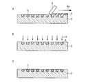
- 2A to 2C are side cross-sectional views showing an example of a manufacturing process of the polarization beam splitting element according to the present invention
- FIG. 2A is a side cross-sectional view showing a process of filling a liquid crystal liquid crystal in a groove of a substrate having irregularities.
- FIG. 1A and 1B are side cross-sectional views illustrating an example of a polarization separation element according to the present invention
- FIG. 1A is a side view illustrating a polarization separation element in which a polymer liquid
- FIG. 2B is a side cross-sectional view showing the process of polymerizing and curing the filled polymerizable liquid crystal with ultraviolet rays to form a polymer liquid crystal
- FIG. 2C is a side cross-sectional view showing the structure of the produced polarization separation element.
- 3A to 3E are side cross-sectional views showing another example of the manufacturing process of the polarization beam splitter according to the present invention
- FIG. 3A is a side view showing the process of filling the liquid crystal liquid crystal in the groove of the uneven mold.
- Sectional view, FIG. 3B is a side sectional view showing the process of polymerizing and curing the filled polymerizable liquid crystal with ultraviolet rays to form a polymer liquid crystal
- FIG. 3C is a liquid ultraviolet curable resin and glass on a mold filled with the polymer liquid crystal
- FIG. 3D is a side sectional view showing a process of transferring a polymer liquid crystal to a substrate by laminating plates and polymerizing and curing an ultraviolet curable resin with ultraviolet rays to form a transparent isotropic medium.
- FIG. 3D is a diagram showing a transparent isotropic medium on the substrate.
- FIG. 3E is a side cross-sectional view showing a process of applying a liquid ultraviolet curable resin on the polymer liquid crystal lattice transferred in this manner and polymerizing and curing the ultraviolet curable resin with ultraviolet rays to form another transparent isotropic medium.
- Side view showing the structure of the polarization separation element It is a surface view.
- a polymerizable liquid crystal is filled in a groove formed in a predetermined shape in advance.
- the polymerizable liquid crystal is spontaneously aligned in the longitudinal direction of the groove without any special alignment treatment due to the interaction between the groove wall surface and the liquid crystal molecules.
- the polymerizable liquid crystal is polymerized into a polymer liquid crystal while maintaining the alignment state.
- the orientation direction of the polymer liquid crystal can be controlled with high accuracy in the longitudinal direction of the groove without using the liquid crystal alignment film, and the thickness of the liquid crystal layer is also controlled by the depth of the groove formed in advance. be able to.
- the polymerizable liquid crystal for forming the polymer liquid crystal lattice used in the present invention is a composition such as a monomer, oligomer or other reactive compound exhibiting liquid crystallinity.
- the curing method of irradiating light there are a method of irradiating light such as visible light and UV (ultraviolet) light, a method of heating, etc., but the curing method of irradiating light depends on the phase transition temperature of the polymerizable liquid crystal. It is preferable because it is difficult to be restricted. Therefore, here, a case where the polymerizable liquid crystal is polymerized and cured by light irradiation will be described. In this specification, for the sake of convenience, the unpolymerized state of the liquid crystal is referred to as “polymerizable liquid crystal” and the polymerized state is referred to as “polymer liquid crystal”.
- FIG. 1A and 1B show an example of the structure of a polarization separation element having a polymer liquid crystal lattice according to the present invention.
- FIG. 1A shows a cross-sectional view of an example of the polarization separation element of the present invention, in which 1 is a lattice made of a polymer liquid crystal, and 2 is a substrate made of an isotropic medium.
- the liquid crystal molecules are spontaneously aligned along the longitudinal direction of the groove by filling the liquid crystal with the polymerizable liquid crystal in the groove of the substrate 2 having a predetermined concavo-convex shape formed in advance, due to the molecular interaction between the groove wall surface and the liquid crystal. Therefore, the liquid crystal can be aligned in the longitudinal direction of the groove without particularly performing an alignment treatment on the surface of the substrate.
- a polarization separation element having optical anisotropy can be stably produced.
- the ordinary refractive index of the refractive index of the polymer liquid crystal (n o) or equal isotropic medium to the extraordinary refractive index (n e) is, the polarization separation performance of the linear polarization direction of the incident light It is desirable to increase
- a transparent glass plate or plastic plate As the substrate 2, a transparent glass plate or plastic plate, a so-called 2P (Photo Polymer) substrate in which an uneven shape is transferred to an ultraviolet curable resin mainly composed of an acrylic radical polymerization monomer coated on the glass substrate, and the like are used.
- a glass plate is preferable in terms of mass production and easy formation of grooves, and plastics in terms of hardness and durability.
- a 2P substrate that only needs to match the refractive index of the polymer liquid crystal with the refractive index of the UV resin cured product forming the groove is preferable. Further, if necessary, the uneven surface of the substrate can be subjected to a treatment for strengthening the adhesive force.
- a polymerizable liquid crystal having a mesogenic group that exhibits a liquid crystal state and a functional group having a polymerizable property such as acrylic or epoxy is suitable, and the liquid crystal state before polymerization has the nematic state most. Is suitable.
- FIG. 1B is a cross-sectional view showing another example of the polarization separation element of the present invention. As shown in the figure, it is also possible to cover the lattice made of the polymer liquid crystal 1 with another transparent isotropic medium 3.
- Reference numeral 4 denotes a transparent substrate made of glass or plastic.
- the isotropic medium 3 is most preferably an ultraviolet curable resin.
- an acrylic modified type is used for the polymerizable liquid crystal forming the polymer liquid crystal 1
- the polymer liquid crystal 1 and the isotropic medium 3 are strong by using an acrylic ultraviolet curable resin for the isotropic medium 3. Adhesion can be obtained.
- the isotropic medium 2 surrounding the polymer liquid crystal 1 polymerized, the ordinary refractive index (n o) or the extraordinary refractive index (n e) equal isotropic medium with a refractive index of the polymer liquid crystal film is, the incident light It is desirable to improve the polarization separation performance by the linear polarization direction.
- the isotropic medium 2 for example, a photopolymerizable acrylic resin or epoxy resin can be used.
- the materials of the isotropic media 2 and 3 may be different or the same.
- the polarization separation element of the present invention is not limited to FIGS. 1A and 1B.
- the optical axis of the polymer liquid crystal is parallel to the longitudinal direction of the grooves.
- the alignment of the liquid crystal layer is generated by the interaction between the liquid crystal molecules and the wall surface of the groove, so that the optical axis of the resulting polymer liquid crystal is limited only to the longitudinal direction of the groove.
- This is not a restriction when used as a polarization separation element. Rather, for example, by providing a plurality of regions having different groove directions in one element, it is easy to provide a plurality of regions in which polymer liquid crystal lattices having different orientation directions are formed. However, in this case, the polymer liquid crystal lattice that does not diffract the polarized light and the polymer liquid crystal lattice that completely diffracts the polarized light are limited according to the polarization direction of the incident polarized light.
- the polarization separation element of the present invention is not limited to this and can be applied to a reflection type element.
- Example 1 1B shows an embodiment of the polarization separation element shown in FIG. 1A.
- 2A to 2C show side cross-sectional views of each process of the first manufacturing method of the polarization beam splitting element in which the stripe-like structure made of polymer liquid crystal is arranged.
- a glass substrate was used in which an ultraviolet curable resin layer having a plurality of parallel grooves on the surface each having a groove width of 10 ⁇ m, a groove pitch of 20 ⁇ m, and a depth of 8 ⁇ m was laminated on the surface (in FIGS. 2A to 2C, (The illustration is omitted).
- This substrate 2 is coated with a liquid UV curable resin on a die having a surface plated with Ni-P electroless plating, and is laminated with a glass substrate. After the resin was cured and the groove shape was transferred to the ultraviolet curable resin, the glass substrate and the ultraviolet curable resin layer were integrally peeled off to produce the so-called 2P method.
- RMS03-001C manufactured by Merck
- liquid polymerizable liquid crystal 5 is dropped on the uneven surface of the substrate 2
- the solvent is heated and dried, and the temperature is returned to room temperature.
- the surface of the substrate 2 was flattened by removing the polymerizable liquid crystal protruding from the groove of the substrate 2.
- An arrow 6a indicates the moving direction of the squeegee 6.
- the polymerizable liquid crystal 5 was reacted and cured by irradiation with ultraviolet rays 11 mainly having a wavelength of 365 nm to obtain a polarization separation element as shown in FIG. 2C.
- the polarized light separating element is irradiated with polarized red laser light
- the polarization direction is matched with the stripe direction (groove direction) of the polymer liquid crystal 1
- the intensity of diffracted light with respect to the orthogonal direction It was confirmed by visual observation that a large change in the light intensity was obtained, and it was confirmed that good polarized light was obtained by the present invention.
- the cured product of RMS03-001C has an ordinary light refractive index of 1.529 and an extraordinary light refractive index of 1.684, and the refractive index of the ultraviolet curable resin surrounding the polymer liquid crystal is lower than those. Is considered that the film thickness of the polymerizable liquid crystal in the groove changes due to volume shrinkage upon curing.
- Example 2 shows an embodiment of the polarization separation element shown in FIG. 1B.
- 3A to 3C are side cross-sectional views of each process of the second manufacturing method of the polarization separating element in which the stripe-like structure made of polymer liquid crystal is arranged.
- RMS03-001C polymerizable liquid crystal 5 is formed on a mold 7 on the surface of which a plurality of parallel grooves having a groove width of 10 ⁇ m, a groove pitch of 20 ⁇ m, and a depth of 8 ⁇ m are formed.
- Merck was added dropwise, the solvent was heated to dryness, and the temperature was returned to room temperature.
- the surface of the mold 7 was leveled with a squeegee 6 to remove the polymerizable liquid crystal protruding from the groove of the mold 7 and remove the surface. Flattened.
- An arrow 6a indicates the moving direction of the squeegee 6.
- the mold 7 has a Ni—P electroless plated surface with grooves formed by machining.
- the polymerizable liquid crystal 5 was reacted and cured by irradiation with ultraviolet rays 11 mainly having a wavelength of 365 nm.
- a liquid ultraviolet curable resin is applied onto a mold 7 in which the polymer liquid crystal 1 is filled in the groove, and an adhesion reinforcing film made of KBM-503 (manufactured by Shin-Etsu Chemical) is formed on the surface.
- a glass substrate 4 having a thickness of 0.5 mm on which (not shown) was formed was laminated, and ultraviolet rays 12 mainly having a wavelength of 365 nm were irradiated to react and cure the ultraviolet curable resin.
- the transparent isotropic medium 3 made of the cured ultraviolet curable resin is firmly bonded to the polymer liquid crystal 1, the lattice made of the polymer liquid crystal 1 can be transferred to the glass substrate 4 side.
- FIG. 3D After that, after peeling the lattice made of the polymer liquid crystal 1 integrated with the glass substrate 4 through the isotropic medium 3 from the mold 7, the polymer liquid crystal on the isotropic medium 3 is shown in FIG. 3D.
- An isotropic medium 2 made of a transparent resin is formed by applying a liquid ultraviolet curable resin different from the above to the surface of 1 and irradiating ultraviolet rays 13 mainly having a wavelength of 365 nm to react and cure the ultraviolet curable resin. did.
- a polarization separation element as shown in FIG. 3E was prepared.
- the ultraviolet curable resin constituting the isotropic medium 2 is 20 parts by weight of 1,6 hexyl diacrylate (manufactured by Kyoeisha Chemical Co., Ltd.), hydroxybutyl methacrylate (manufactured by Kyoeisha Chemical Co., Ltd.), and 2-hydroxy-3- as a refractive index adjuster.
- the polarized light separating element obtained is irradiated with polarized red laser light
- the polarization direction is matched with the stripe direction of the polymer liquid crystal 1
- the diffracted light intensity greatly changes in the orthogonal direction. This was confirmed visually, and it was confirmed that good polarized light was obtained by the present invention.
Landscapes
- Physics & Mathematics (AREA)
- General Physics & Mathematics (AREA)
- Optics & Photonics (AREA)
- Chemical & Material Sciences (AREA)
- Crystallography & Structural Chemistry (AREA)
- Polarising Elements (AREA)
- Diffracting Gratings Or Hologram Optical Elements (AREA)
Abstract
所定形状の格子溝に重合性液晶を充填し、次いで重合性液晶を硬化することで、液晶配向膜を使わずに、配向方位が溝の長手方向と一致した一軸性高分子液晶よりなるストライプ状構造を形成する。これにより、配向膜を使わずに高分子液晶を良好に安定して配向させることができ、さらに膜厚の調整も容易になるため、分離効率が高くかつ分離効率の均一性のよい偏光分離素子を安定して得ることができる。
Description
本発明は、分離素子およびその製造方法に関する。
従来、高分子液晶を使用した偏光性分離素子では、2枚の透明基板上にポリイミド樹脂を塗布・熱硬化したのちバフ研磨による配向処理を行って液晶配向膜を形成したのち、両基板間に重合性液晶材料を充填し、重合性液晶が液晶状態である温度でフォトマスクを介して光露光して格子を形成した後、重合性液晶が等方状態となる温度まで昇温して未硬化の重合性液晶を架橋させることで所定形状の格子を形成した高分子液晶薄膜を作製し、光学的異方性を有する回折格子を形成していた。
しかし、この方法では形成された配向膜による重合性液晶の配向状態を安定して管理することが難しく、またバフ研磨後に洗浄工程が必須であるという問題をもっていた。
本発明の目的は、従来技術の前述のような問題を解決し、高分子液晶薄膜を使用した分離素子およびその製造方法を新規に提供することである。
本発明の偏光分離素子は、一軸性高分子液晶よりなるストライプ状構造を配列した偏光分離素子において、一軸性高分子液晶よりなるストライプ状構造が等方性媒質中に形成され、かつ高分子液晶の光軸がストライプ状構造の長手方向に一致することを特徴とする。
また、本発明の偏光分離素子の第1の製造方法は、媒質に形成された所定形状の溝に重合性液晶を充填したのち硬化させ、溝の長手方向に光学異方軸を配向させた高分子液晶格子を形成することを特徴とする。
本発明の偏光分離素子の第2の製造方法は、転写用金型に形成された所定形状の溝に重合性液晶を充填したのち硬化させ高分子液晶とし、前記高分子液晶を等方性媒質にて基材上に転写したのち、等方性媒質にて前記高分子液晶による格子間隙を充填することを特徴とする。
本発明の分離素子の構成および製造方法を採用することにより、特別な配向膜を使わずに高分子液晶を良好に安定して配向させることができ、さらに膜厚の調整も容易になるため、分離効率が高くかつ分離効率の均一性のよい偏光分離素子を安定して得ることができる。
上記の課題に対し、本発明においては、あらかじめ所定形状に形成された溝に重合性液晶を充填する。重合性液晶は、溝壁面と液晶分子の相互作用により特別な配向処理を施すことなく自発的に溝の長手方向に配向する。その後、その配向状態を維持したまま重合性液晶を重合させ高分子液晶とする。これにより、高分子液晶の配向方位を、液晶配向膜を介することなく溝の長手方向に高い精度で制御することができるとともに、液晶層の厚さもあらかじめ形成してある溝の深さにより制御することができる。
本発明で用いる高分子液晶格子を形成するための重合性液晶は、液晶性を示すモノマー、オリゴマーその他の反応性化合物などの組成物である。
重合性液晶を硬化する方法としては、可視光やUV(紫外)光などの光を照射する方法や、加熱する方法などがあるが、光を照射する硬化方法が重合性液晶の相転移温度による制約を受けにくいために好ましい。したがって、ここでは光の照射によって重合性液晶を重合して硬化する場合を説明する。なお、本明細書では便宜上この液晶が未重合の状態を「重合性液晶」、高分子化した状態を「高分子液晶」と呼んで区別することとする。
本発明による高分子液晶格子を備えた偏光分離素子の構造の一例を図1A及び図1Bに示す。
図1Aは本発明の偏光分離素子の一例の断面図を示すもので、図中、1は高分子液晶からなる格子、2は等方性媒質からなる基板である。この構成ではあらかじめ所定の凹凸形状を形成した基板2の溝に重合性液晶を充填することで、溝壁面と液晶の間の分子相互作用により自発的に液晶分子が溝の長手方向に沿って整列するため、基板の表面に特に配向処理を施すことなく液晶を溝の長手方向に配向させることができる。この状態で重合性液晶を硬化させると光学異方性を有する偏光分離素子を安定して作成することができる。
本構成に用いる基板2としては、屈折率が高分子液晶の常光屈折率(no)又は異常光屈折率(ne)に等しい等方性媒質が、入射光の直線偏光方位による偏光分離性能を高める上で望ましい。
基板2としては、透明なガラス板やプラスチック板、ガラス基板上に塗布されたアクリル系ラジカル重合モノマーを主成分とする紫外線硬化樹脂に凹凸形状が転写されたいわゆる2P(Photo Polymer)基板などが使用できるが、量産性や溝の成形が容易な点ではプラスチック、硬度や耐久性などに優れる点ではガラス板が好ましい。
また液晶層との屈折率のマッチングが容易な点では溝を形成するUV樹脂硬化物の屈折率のみ高分子液晶の屈折率とあわせればよい2P基板が好ましい。また、必要に応じて基板の凹凸面には接着力強化のための処理を施すこともできる。
また、重合性液晶には液晶状態を発現するメソゲン基の末端にアクリル、エポキシ等の重合性を有する官能基を付けたものが好適であり、重合前の液晶状態でネマティック状態を持つものが最も適している。
図1Bは本発明の偏光分離素子の別の例を示した断面図である。図示するように、高分子液晶1からなる格子を別の透明な等方性媒質3で被覆することも可能である。4はガラス又はプラスチック等からなる透明な基板である。
等方性媒質3としては紫外線硬化樹脂がもっとも好適である。特に高分子液晶1を形成する重合性液晶にアクリル変性型を使う場合は、等方性媒質3にアクリル系紫外線硬化樹脂を使うことにより高分子液晶1と等方性媒質3との間に強い接着を得ることができる。
重合した高分子液晶1を囲む等方性媒質2としては、屈折率が高分子液晶薄膜の常光屈折率(no)又は異常光屈折率(ne)に等しい等方性媒質が、入射光の直線偏光方位による偏光分離性能を高める上で望ましい。等方性媒質2としては例えば光重合型のアクリル系樹脂やエポキシ系樹脂などを使用できる。
等方性媒質2,3の材料は、異なっていてもよいし、同じであってもよい。
本発明の偏光分離素子は図1A及び図1Bに限定されない。たとえば本発明の偏光分離素子を別の透明部材で挟持した構成や、他の光学部材と積層した構成とすることも可能である。
上述した本発明の構成において、液晶分子は溝の壁面との相互作用により自発的に溝に対し平行方向に配列するため、高分子液晶の光軸が溝の長手方向に平行となる。
この効果は溝の断面形状が矩形、三角形、半円形等いずれであっても発現するため用途によって適切な形状を選択することができるが、回折格子に使う場合は矩形形状、三角形が望ましい。
また、本発明の構成では液晶層の配向が液晶分子と溝の壁面との相互作用により発生するため出来上がった高分子液晶の光軸は溝の長手方向のみに限定される。これは偏光分離素子として使う場合にはまったく制約とならない。むしろ、たとえば1素子中に溝の方向が異なる複数領域を設けることで、配向方位が異なる高分子液晶格子が形成された複数の領域を設けることも容易となる利点がある。ただし、この場合、入射する偏光光の偏光方向に応じて、偏光光を回折させない高分子液晶格子と完全に回折させる高分子液晶格子はそれぞれ限定される。
また、上記の偏光分離素子は光透過型素子であったが、本発明の偏光分離素子はこれに限定されず、反射型素子にも適用できる。
以下本発明の実施例について、図面を参照しながら説明する。
(実施例1)
図1Aに示した偏光分離素子の実施例を示す。高分子液晶よりなるストライプ状構造を配列した偏光分離素子の第1の製造方法の各プロセスの側面断面図を図2A~図2Cに示した。
図1Aに示した偏光分離素子の実施例を示す。高分子液晶よりなるストライプ状構造を配列した偏光分離素子の第1の製造方法の各プロセスの側面断面図を図2A~図2Cに示した。
基板2として溝幅10μm、溝ピッチ20μm、深さ8μmの互いに平行な複数の溝を表面に形成した紫外線硬化樹脂層を表面に積層したガラス基板を使用した(図2A~図2Cではガラス基板の図示を省略している)。この基板2は、表面がNi-P無電解メッキされた金型に機械加工により溝を形成した金型に液状紫外線硬化樹脂を塗布し、ガラス基板を積層した後、紫外線を照射して紫外線硬化樹脂を硬化して紫外線硬化樹脂に溝形状を転写したのち、ガラス基板と紫外線硬化樹脂層を一体に剥がしとるいわゆる2P法により作成した。紫外線硬化樹脂としてはジシクロペンタジエニルヘキサアクリレート(共栄社化学製)20重量部に、イソボルニルアクリレート(共栄社化学製)と、屈折率調整剤としてフェノキシアクリレート(共栄社化学製)をあわせて80重量部、重合開始剤としてイルガキュア184(チバスペシャリティケミカルズ製)3重量部を混合し、硬化物での屈折率を1.525としたものを使用した。
まず図2Aに示すように液状の重合性液晶5としてRMS03-001C(メルク製)を基板2の凹凸面に滴下し、溶剤を加熱乾燥させたのち室温まで戻したのち、基板2の表面をスキージ6にて均し、基板2の溝よりはみ出した重合性液晶を除去して表面を平坦化させた。矢印6aはスキージ6の移動方向を示す。
この状態で次に図2Bに示すように365nmの波長を主とした紫外線11を照射をして重合性液晶5を反応硬化させ、図2Cのような偏光分離素子とした。
ストライプ状構造を有する高分子液晶1の配向状態を偏光顕微鏡にて観察するとそのストライプ方向(溝方向)に高分子液晶格子の分子軸が配向していることが観察され、良好な配向状態であることが確認された。
基板2への滴下直後およびスキージ6による溝への充填後のそれぞれについて、液状の重合性液晶5の配向状態を偏光顕微鏡で観察したところ、滴下直後では強い配向状態は見られなかったのに対し、スキージ6による溝への充填後では溝の長手方向に平行な強い配向が観察された。これは液晶分子が基板2の壁面に平行に並ぶ性質を持つため、複数の壁面で囲まれた溝中では液晶分子が自発的に溝に対し平行方向に配列したためと考えられる。
スキージング時に重合性液晶を完全に溝内のみ残留させることは難しく、ごく少量の重合性液晶が溝と溝の間の平坦部に残留するが、この部分の重合性液晶は溝による強い配向規制を受けないためランダム配向となり、かつ厚さも非常に薄いため、出来上がった格子の偏光状態には影響しない。
また、得られた偏光分離素子に対して偏光させた赤色レーザ光を照射したところ、偏光方向を高分子液晶1のストライプ方向(溝方向)にあわせた場合、その直交方向に対して回折光強度が大きく変化することが目視で確認でき、本発明により良好な偏光回折光が得られることを確認できた。
なお、RMS03-001Cの硬化物の常光線屈折率は1.529、異常光屈折率は1.684であり、高分子液晶を囲む紫外線硬化樹脂の屈折率はそれらより低くしているが、これは溝中の重合性液晶が硬化時に体積収縮してその膜厚が変化することを考慮したものである。
(実施例2)
図1Bに示した偏光分離素子の実施例を示す。高分子液晶よりなるストライプ状構造を配列した偏光分離素子の第2の製造方法の各プロセスの側面断面図を図3A~図3Cに示した。
図1Bに示した偏光分離素子の実施例を示す。高分子液晶よりなるストライプ状構造を配列した偏光分離素子の第2の製造方法の各プロセスの側面断面図を図3A~図3Cに示した。
本実施例においては、まず図3Aに示すように溝幅10μm、溝ピッチ20μm、深さ8μmの互いに平行な複数の溝を表面に形成した金型7上に重合性液晶5としてRMS03-001C(メルク製)を滴下し、溶剤を加熱乾燥させたのち室温まで戻したのち、金型7の表面をスキージ6にて均し、金型7の溝よりはみ出した重合性液晶を除去して表面を平坦化させた。矢印6aはスキージ6の移動方向を示す。なお、この金型7はNi-P無電解メッキされた表面に機械加工により溝を形成したものである。
この状態で次に図3Bに示すように365nmの波長を主とした紫外線11を照射をして重合性液晶5を反応硬化させた。
次に図3Cに示すように溝に高分子液晶1が充填された金型7上に液状紫外線硬化樹脂を塗布し、その上に、表面にKBM-503(信越化学製)からなる接着強化膜(図示せず)を形成した0.5mm厚のガラス基板4を積層し、365nmの波長を主とした紫外線12を照射をして紫外線硬化樹脂を反応硬化させた。液状紫外線硬化樹脂としてはジシクロペンタジエニルヘキサアクリレート(共栄社化学製)20重量部に、イソボルニルアクリレート(共栄社化学製)と、屈折率調整剤としてフェノキシアクリレート(共栄社化学製)をあわせて80重量部、重合開始剤としてイルガキュア184(チバスペシャリティケミカルズ製)3重量部を混合し、硬化物での屈折率を1.53としたものを使用した。
この段階で、硬化した紫外線硬化樹脂よりなる透明等方性媒質3は高分子液晶1と強固に接着するため、ガラス基板4側に高分子液晶1からなる格子を転写することが可能となる。
そののち等方性媒質3を介してガラス基板4と一体化した高分子液晶1からなる格子を金型7から剥がし取ったのち、図3Dに示すように等方性媒質3上の高分子液晶1の表面に上記とは別の液状の紫外線硬化樹脂を塗布し、365nmの波長を主とした紫外線13を照射して紫外線硬化樹脂を反応硬化させて透明樹脂よりなる等方性媒質2を形成した。かくして図3Eのような偏光分離素子を作成した。等方性媒質2を構成する紫外線硬化樹脂としては1,6ヘキシルジアクリレート(共栄社化学製)20重量部に、ヒドロキシブチルメタクリレート(共栄社化学製)と、屈折率調整剤として2-ヒドロキシ-3-フェノキシプロピルアクリレート(共栄社化学製)をあわせて80重量部、重合開始剤としてイルガキュア184(チバスペシャリティケミカルズ製)3重量部を混合し、硬化物での屈折率を1.53としたものを使用した。
ストライプ状構造を有する高分子液晶1の配向状態を偏光顕微鏡にて観察するとそのストライプ方向に高分子液晶格子の分子軸が配向していることが観察され、良好な配向状態であることが確認された。
また、得られた偏光分離素子に対して偏光させた赤色レーザ光を照射したところ、偏光方向を高分子液晶1のストライプ方向にあわせた場合、その直交方向に対して回折光強度が大きく変化することが目視で確認でき、本発明により良好な偏光回折光が得られることを確認できた。
1:高分子液晶
2:等方性媒質(基板)
3:等方性媒質
4:透明基板
5:重合性液晶
6:スキージ
7:金型
2:等方性媒質(基板)
3:等方性媒質
4:透明基板
5:重合性液晶
6:スキージ
7:金型
Claims (4)
- 一軸性高分子液晶よりなるストライプ状構造を配列した偏光分離素子において、一軸性高分子液晶よりなるストライプ状構造が等方性媒質中に形成され、かつ高分子液晶の光軸がストライプ状構造の長手方向に一致することを特徴とする偏光分離素子。
- 高分子液晶と等方性媒質が液晶配向膜を介することなく直接に接することを特徴とする請求項1記載の偏光分離素子。
- 媒質に形成された所定形状の溝に重合性液晶を充填したのち硬化させ、溝の長手方向に光学異方軸を配向させた高分子液晶格子を形成することを特徴とする偏光分離素子の製造方法。
- 転写用金型に形成された所定形状の溝に重合性液晶を充填したのち硬化させ高分子液晶とし、前記高分子液晶を等方性媒質にて基材上に転写したのち、等方性媒質にて前記高分子液晶からなる格子間隙を充填することを特徴とする偏光分離素子の製造方法。
Priority Applications (2)
| Application Number | Priority Date | Filing Date | Title |
|---|---|---|---|
| US13/143,434 US20110273658A1 (en) | 2009-04-13 | 2010-03-05 | Polarization split element and method for manufacturing the same |
| CN2010800082317A CN102317824A (zh) | 2009-04-13 | 2010-03-05 | 偏振光分离元件及其制造方法 |
Applications Claiming Priority (2)
| Application Number | Priority Date | Filing Date | Title |
|---|---|---|---|
| JP2009-097112 | 2009-04-13 | ||
| JP2009097112A JP2010249937A (ja) | 2009-04-13 | 2009-04-13 | 偏光分離素子およびその製造方法 |
Publications (1)
| Publication Number | Publication Date |
|---|---|
| WO2010119735A1 true WO2010119735A1 (ja) | 2010-10-21 |
Family
ID=42982403
Family Applications (1)
| Application Number | Title | Priority Date | Filing Date |
|---|---|---|---|
| PCT/JP2010/053671 Ceased WO2010119735A1 (ja) | 2009-04-13 | 2010-03-05 | 偏光分離素子およびその製造方法 |
Country Status (4)
| Country | Link |
|---|---|
| US (1) | US20110273658A1 (ja) |
| JP (1) | JP2010249937A (ja) |
| CN (1) | CN102317824A (ja) |
| WO (1) | WO2010119735A1 (ja) |
Families Citing this family (5)
| Publication number | Priority date | Publication date | Assignee | Title |
|---|---|---|---|---|
| CN103207455A (zh) * | 2012-01-12 | 2013-07-17 | 深圳市亿思达显示科技有限公司 | 立体显示装置 |
| US10026030B2 (en) * | 2012-01-13 | 2018-07-17 | Empire Technology Development Llc | Simple diffraction gratings for product identification |
| CN108957611B (zh) * | 2018-07-13 | 2021-05-14 | 歌尔股份有限公司 | 一种光栅片的制造方法、光栅片及显示设备 |
| CN111708112B (zh) * | 2020-08-20 | 2021-01-22 | 歌尔股份有限公司 | 液晶体光栅的制作方法 |
| CN117826303A (zh) * | 2022-09-27 | 2024-04-05 | 苏州苏大维格科技集团股份有限公司 | 偏振薄膜及其制作方法、光波导镜片、显示装置 |
Citations (5)
| Publication number | Priority date | Publication date | Assignee | Title |
|---|---|---|---|---|
| JPH09127335A (ja) * | 1995-11-02 | 1997-05-16 | Asahi Glass Co Ltd | 光ヘッド装置の製造方法及び光ヘッド装置 |
| JP2004212553A (ja) * | 2002-12-27 | 2004-07-29 | Ricoh Co Ltd | 偏光回折光学素子及び光ピックアップ装置及び光ディスクドライブ装置 |
| JP2007206095A (ja) * | 2006-01-30 | 2007-08-16 | Fujifilm Corp | 偏光変換フィルム及びその製造方法、偏光素子、並びに液晶表示装置 |
| WO2007145246A1 (ja) * | 2006-06-14 | 2007-12-21 | Hitachi Chemical Co., Ltd. | 樹脂組成物、およびこれを用いてなる積層型光学部材 |
| JP2008233226A (ja) * | 2007-03-16 | 2008-10-02 | Ricoh Co Ltd | 光束分割素子 |
Family Cites Families (5)
| Publication number | Priority date | Publication date | Assignee | Title |
|---|---|---|---|---|
| WO1997013245A1 (fr) * | 1995-10-03 | 1997-04-10 | Asahi Glass Company Ltd. | Dispositif tete optique et procede de fabrication associe |
| US6618116B1 (en) * | 1997-10-02 | 2003-09-09 | Asahi Glass Company, Limited | Optical head device and a diffraction element suitable for the device, and a method of manufacturing the diffraction element and the optical head device |
| EP1744904B2 (de) * | 2004-04-30 | 2019-11-06 | Giesecke+Devrient Currency Technology GmbH | Folienmaterial und verfahren zu seiner herstellung |
| JPWO2008062698A1 (ja) * | 2006-11-24 | 2010-03-04 | 日本電気株式会社 | 光ヘッド装置及び光学式情報記録再生装置 |
| US7835252B2 (en) * | 2007-04-12 | 2010-11-16 | Asahi Glass Company, Limited | Optical head apparatus |
-
2009
- 2009-04-13 JP JP2009097112A patent/JP2010249937A/ja not_active Withdrawn
-
2010
- 2010-03-05 WO PCT/JP2010/053671 patent/WO2010119735A1/ja not_active Ceased
- 2010-03-05 US US13/143,434 patent/US20110273658A1/en not_active Abandoned
- 2010-03-05 CN CN2010800082317A patent/CN102317824A/zh active Pending
Patent Citations (5)
| Publication number | Priority date | Publication date | Assignee | Title |
|---|---|---|---|---|
| JPH09127335A (ja) * | 1995-11-02 | 1997-05-16 | Asahi Glass Co Ltd | 光ヘッド装置の製造方法及び光ヘッド装置 |
| JP2004212553A (ja) * | 2002-12-27 | 2004-07-29 | Ricoh Co Ltd | 偏光回折光学素子及び光ピックアップ装置及び光ディスクドライブ装置 |
| JP2007206095A (ja) * | 2006-01-30 | 2007-08-16 | Fujifilm Corp | 偏光変換フィルム及びその製造方法、偏光素子、並びに液晶表示装置 |
| WO2007145246A1 (ja) * | 2006-06-14 | 2007-12-21 | Hitachi Chemical Co., Ltd. | 樹脂組成物、およびこれを用いてなる積層型光学部材 |
| JP2008233226A (ja) * | 2007-03-16 | 2008-10-02 | Ricoh Co Ltd | 光束分割素子 |
Also Published As
| Publication number | Publication date |
|---|---|
| US20110273658A1 (en) | 2011-11-10 |
| JP2010249937A (ja) | 2010-11-04 |
| CN102317824A (zh) | 2012-01-11 |
Similar Documents
| Publication | Publication Date | Title |
|---|---|---|
| JP5273248B2 (ja) | 微細凹凸構造を表面に有する物品の製造方法およびワイヤグリッド型偏光子の製造方法 | |
| KR101911568B1 (ko) | 광학 소자, 표시 장치 및 입력 장치 | |
| JP4999556B2 (ja) | 表面に微細凹凸形状をもつ光学素子の製造方法 | |
| CN102193125A (zh) | 偏振性衍射光栅及其制造方法以及使用其的光拾取装置 | |
| JP6865795B2 (ja) | 光配向可能な物品 | |
| TWI519866B (zh) | A method of manufacturing a liquid crystal element, and a liquid crystal cell | |
| JP2005516236A (ja) | パターン化した光学素子の製造方法 | |
| JPH026927A (ja) | 積層光学素子の製造方法およびこれにより製造された積層光学素子 | |
| KR20190029489A (ko) | 회절 도광판 및 회절 도광판의 제조 방법 | |
| WO2010119735A1 (ja) | 偏光分離素子およびその製造方法 | |
| WO2020004497A1 (ja) | 光学素子及び光学素子の製造方法 | |
| JP2003315540A (ja) | 偏光回折素子及びその作製方法 | |
| WO2010113592A1 (ja) | 光学的情報記録媒体の製造方法及び光学的情報記録媒体 | |
| KR101538776B1 (ko) | 점착 내구성 및 투과도 균일도가 향상된 스마트 윈도우 필름 및 스마트 윈도우 필름 제조 방법 | |
| TW201912375A (zh) | 三維構造物之製造方法、三維構造物及製造三維構造物之製造裝置 | |
| CN1399729A (zh) | 通过同时进行对准排列和相分离制造对准排列的液晶单元/膜 | |
| US6939587B1 (en) | Fabrication of aligned crystal cell/film by simultaneous alignment and phase separation | |
| KR20060048107A (ko) | 표면 미세 구조를 갖는 메타크릴계 수지 성형체 및 그 제조방법 | |
| JP6045782B2 (ja) | 微細凹凸パタン基材及びその製造方法、並びに、ワイヤグリッド偏光板及びその製造方法 | |
| JP2006343758A (ja) | 反射防止方法及び反射防止構造並びに反射防止構造を有する反射防止構造体及びその製造方法 | |
| KR101536225B1 (ko) | 회절광 노이즈를 제거한 액정상 고분자 필름 및 그 제조방법 | |
| TWI457665B (zh) | 圖案相位延遲膜及其製造方法 | |
| CN101452088B (zh) | 低或零双折射光学薄膜及其制造方法 | |
| JP5648458B2 (ja) | 積層体を製造する方法、積層体、光学補償素子、及び液晶デバイス | |
| JP4051747B2 (ja) | 回折素子の製造方法 |
Legal Events
| Date | Code | Title | Description |
|---|---|---|---|
| WWE | Wipo information: entry into national phase |
Ref document number: 201080008231.7 Country of ref document: CN |
|
| 121 | Ep: the epo has been informed by wipo that ep was designated in this application |
Ref document number: 10764321 Country of ref document: EP Kind code of ref document: A1 |
|
| NENP | Non-entry into the national phase |
Ref country code: DE |
|
| 122 | Ep: pct application non-entry in european phase |
Ref document number: 10764321 Country of ref document: EP Kind code of ref document: A1 |