WO2010113997A1 - マイクロ流路チップ及びそれを用いた気液相分離方法 - Google Patents
マイクロ流路チップ及びそれを用いた気液相分離方法 Download PDFInfo
- Publication number
- WO2010113997A1 WO2010113997A1 PCT/JP2010/055797 JP2010055797W WO2010113997A1 WO 2010113997 A1 WO2010113997 A1 WO 2010113997A1 JP 2010055797 W JP2010055797 W JP 2010055797W WO 2010113997 A1 WO2010113997 A1 WO 2010113997A1
- Authority
- WO
- WIPO (PCT)
- Prior art keywords
- microchannel
- gas
- liquid phase
- liquid
- phase flow
- Prior art date
Links
- 239000007791 liquid phase Substances 0.000 title claims abstract description 110
- 238000005191 phase separation Methods 0.000 title claims abstract description 77
- 238000000034 method Methods 0.000 title claims abstract description 45
- QGZKDVFQNNGYKY-UHFFFAOYSA-N Ammonia Chemical compound N QGZKDVFQNNGYKY-UHFFFAOYSA-N 0.000 claims abstract description 59
- 239000012071 phase Substances 0.000 claims abstract description 39
- 229910021529 ammonia Inorganic materials 0.000 claims abstract description 29
- 230000005514 two-phase flow Effects 0.000 claims abstract description 24
- 239000000758 substrate Substances 0.000 claims abstract description 20
- 238000007599 discharging Methods 0.000 claims abstract description 5
- 230000002093 peripheral effect Effects 0.000 claims abstract description 5
- 239000007788 liquid Substances 0.000 claims description 51
- 239000000126 substance Substances 0.000 claims description 46
- 238000012360 testing method Methods 0.000 claims description 46
- 238000005259 measurement Methods 0.000 claims description 29
- 239000012528 membrane Substances 0.000 claims description 23
- 238000000605 extraction Methods 0.000 claims description 17
- 230000001590 oxidative effect Effects 0.000 claims description 7
- 239000003153 chemical reaction reagent Substances 0.000 claims description 6
- 239000000463 material Substances 0.000 claims description 6
- 230000002209 hydrophobic effect Effects 0.000 claims description 5
- -1 polytetrafluoroethylene Polymers 0.000 claims description 4
- 239000011148 porous material Substances 0.000 claims description 3
- 229920001343 polytetrafluoroethylene Polymers 0.000 claims description 2
- 239000004810 polytetrafluoroethylene Substances 0.000 claims description 2
- 239000012491 analyte Substances 0.000 claims 2
- 230000035945 sensitivity Effects 0.000 abstract description 5
- 238000000926 separation method Methods 0.000 abstract description 2
- 239000007789 gas Substances 0.000 description 57
- 239000000523 sample Substances 0.000 description 19
- 239000000243 solution Substances 0.000 description 13
- XLYOFNOQVPJJNP-UHFFFAOYSA-N water Substances O XLYOFNOQVPJJNP-UHFFFAOYSA-N 0.000 description 7
- 238000006243 chemical reaction Methods 0.000 description 6
- 239000011521 glass Substances 0.000 description 5
- RSAZYXZUJROYKR-UHFFFAOYSA-N indophenol Chemical compound C1=CC(O)=CC=C1N=C1C=CC(=O)C=C1 RSAZYXZUJROYKR-UHFFFAOYSA-N 0.000 description 5
- 238000004040 coloring Methods 0.000 description 4
- 238000011144 upstream manufacturing Methods 0.000 description 4
- 239000004809 Teflon Substances 0.000 description 3
- 229920006362 Teflon® Polymers 0.000 description 3
- 238000001514 detection method Methods 0.000 description 3
- 238000000691 measurement method Methods 0.000 description 3
- 239000001055 blue pigment Substances 0.000 description 2
- 230000007547 defect Effects 0.000 description 2
- 239000000428 dust Substances 0.000 description 2
- 230000005284 excitation Effects 0.000 description 2
- WQYVRQLZKVEZGA-UHFFFAOYSA-N hypochlorite Chemical compound Cl[O-] WQYVRQLZKVEZGA-UHFFFAOYSA-N 0.000 description 2
- 238000002347 injection Methods 0.000 description 2
- 239000007924 injection Substances 0.000 description 2
- 238000011002 quantification Methods 0.000 description 2
- IJGRMHOSHXDMSA-UHFFFAOYSA-N Atomic nitrogen Chemical compound N#N IJGRMHOSHXDMSA-UHFFFAOYSA-N 0.000 description 1
- 239000004677 Nylon Substances 0.000 description 1
- ISWSIDIOOBJBQZ-UHFFFAOYSA-N Phenol Chemical compound OC1=CC=CC=C1 ISWSIDIOOBJBQZ-UHFFFAOYSA-N 0.000 description 1
- 239000004698 Polyethylene Substances 0.000 description 1
- 239000004743 Polypropylene Substances 0.000 description 1
- 239000004372 Polyvinyl alcohol Substances 0.000 description 1
- 239000005708 Sodium hypochlorite Substances 0.000 description 1
- 239000011248 coating agent Substances 0.000 description 1
- 238000000576 coating method Methods 0.000 description 1
- 230000000052 comparative effect Effects 0.000 description 1
- 238000011161 development Methods 0.000 description 1
- 229910001873 dinitrogen Inorganic materials 0.000 description 1
- 238000010030 laminating Methods 0.000 description 1
- 239000002184 metal Substances 0.000 description 1
- 229910052751 metal Inorganic materials 0.000 description 1
- 229920001778 nylon Polymers 0.000 description 1
- 230000003647 oxidation Effects 0.000 description 1
- 238000007254 oxidation reaction Methods 0.000 description 1
- 238000000059 patterning Methods 0.000 description 1
- 229920013653 perfluoroalkoxyethylene Polymers 0.000 description 1
- 239000004033 plastic Substances 0.000 description 1
- 229920003023 plastic Polymers 0.000 description 1
- 229920000573 polyethylene Polymers 0.000 description 1
- 229920001155 polypropylene Polymers 0.000 description 1
- 229920002451 polyvinyl alcohol Polymers 0.000 description 1
- 238000011160 research Methods 0.000 description 1
- 239000004065 semiconductor Substances 0.000 description 1
- SUKJFIGYRHOWBL-UHFFFAOYSA-N sodium hypochlorite Chemical compound [Na+].Cl[O-] SUKJFIGYRHOWBL-UHFFFAOYSA-N 0.000 description 1
- 239000007787 solid Substances 0.000 description 1
Images


Classifications
-
- B—PERFORMING OPERATIONS; TRANSPORTING
- B01—PHYSICAL OR CHEMICAL PROCESSES OR APPARATUS IN GENERAL
- B01D—SEPARATION
- B01D19/00—Degasification of liquids
- B01D19/0031—Degasification of liquids by filtration
-
- B—PERFORMING OPERATIONS; TRANSPORTING
- B01—PHYSICAL OR CHEMICAL PROCESSES OR APPARATUS IN GENERAL
- B01D—SEPARATION
- B01D53/00—Separation of gases or vapours; Recovering vapours of volatile solvents from gases; Chemical or biological purification of waste gases, e.g. engine exhaust gases, smoke, fumes, flue gases, aerosols
- B01D53/22—Separation of gases or vapours; Recovering vapours of volatile solvents from gases; Chemical or biological purification of waste gases, e.g. engine exhaust gases, smoke, fumes, flue gases, aerosols by diffusion
-
- B—PERFORMING OPERATIONS; TRANSPORTING
- B01—PHYSICAL OR CHEMICAL PROCESSES OR APPARATUS IN GENERAL
- B01D—SEPARATION
- B01D69/00—Semi-permeable membranes for separation processes or apparatus characterised by their form, structure or properties; Manufacturing processes specially adapted therefor
- B01D69/02—Semi-permeable membranes for separation processes or apparatus characterised by their form, structure or properties; Manufacturing processes specially adapted therefor characterised by their properties
-
- B—PERFORMING OPERATIONS; TRANSPORTING
- B01—PHYSICAL OR CHEMICAL PROCESSES OR APPARATUS IN GENERAL
- B01D—SEPARATION
- B01D71/00—Semi-permeable membranes for separation processes or apparatus characterised by the material; Manufacturing processes specially adapted therefor
- B01D71/06—Organic material
- B01D71/30—Polyalkenyl halides
- B01D71/32—Polyalkenyl halides containing fluorine atoms
- B01D71/36—Polytetrafluoroethene
-
- B—PERFORMING OPERATIONS; TRANSPORTING
- B01—PHYSICAL OR CHEMICAL PROCESSES OR APPARATUS IN GENERAL
- B01L—CHEMICAL OR PHYSICAL LABORATORY APPARATUS FOR GENERAL USE
- B01L3/00—Containers or dishes for laboratory use, e.g. laboratory glassware; Droppers
- B01L3/50—Containers for the purpose of retaining a material to be analysed, e.g. test tubes
- B01L3/502—Containers for the purpose of retaining a material to be analysed, e.g. test tubes with fluid transport, e.g. in multi-compartment structures
- B01L3/5027—Containers for the purpose of retaining a material to be analysed, e.g. test tubes with fluid transport, e.g. in multi-compartment structures by integrated microfluidic structures, i.e. dimensions of channels and chambers are such that surface tension forces are important, e.g. lab-on-a-chip
- B01L3/502753—Containers for the purpose of retaining a material to be analysed, e.g. test tubes with fluid transport, e.g. in multi-compartment structures by integrated microfluidic structures, i.e. dimensions of channels and chambers are such that surface tension forces are important, e.g. lab-on-a-chip characterised by bulk separation arrangements on lab-on-a-chip devices, e.g. for filtration or centrifugation
-
- B—PERFORMING OPERATIONS; TRANSPORTING
- B01—PHYSICAL OR CHEMICAL PROCESSES OR APPARATUS IN GENERAL
- B01D—SEPARATION
- B01D2325/00—Details relating to properties of membranes
- B01D2325/02—Details relating to pores or porosity of the membranes
-
- B—PERFORMING OPERATIONS; TRANSPORTING
- B01—PHYSICAL OR CHEMICAL PROCESSES OR APPARATUS IN GENERAL
- B01D—SEPARATION
- B01D2325/00—Details relating to properties of membranes
- B01D2325/02—Details relating to pores or porosity of the membranes
- B01D2325/0283—Pore size
- B01D2325/02834—Pore size more than 0.1 and up to 1 µm
-
- B—PERFORMING OPERATIONS; TRANSPORTING
- B01—PHYSICAL OR CHEMICAL PROCESSES OR APPARATUS IN GENERAL
- B01D—SEPARATION
- B01D2325/00—Details relating to properties of membranes
- B01D2325/04—Characteristic thickness
-
- B—PERFORMING OPERATIONS; TRANSPORTING
- B01—PHYSICAL OR CHEMICAL PROCESSES OR APPARATUS IN GENERAL
- B01D—SEPARATION
- B01D2325/00—Details relating to properties of membranes
- B01D2325/38—Hydrophobic membranes
-
- B—PERFORMING OPERATIONS; TRANSPORTING
- B01—PHYSICAL OR CHEMICAL PROCESSES OR APPARATUS IN GENERAL
- B01L—CHEMICAL OR PHYSICAL LABORATORY APPARATUS FOR GENERAL USE
- B01L2300/00—Additional constructional details
- B01L2300/08—Geometry, shape and general structure
- B01L2300/0809—Geometry, shape and general structure rectangular shaped
- B01L2300/0816—Cards, e.g. flat sample carriers usually with flow in two horizontal directions
-
- B—PERFORMING OPERATIONS; TRANSPORTING
- B01—PHYSICAL OR CHEMICAL PROCESSES OR APPARATUS IN GENERAL
- B01L—CHEMICAL OR PHYSICAL LABORATORY APPARATUS FOR GENERAL USE
- B01L2400/00—Moving or stopping fluids
- B01L2400/04—Moving fluids with specific forces or mechanical means
- B01L2400/0475—Moving fluids with specific forces or mechanical means specific mechanical means and fluid pressure
- B01L2400/0478—Moving fluids with specific forces or mechanical means specific mechanical means and fluid pressure pistons
-
- B—PERFORMING OPERATIONS; TRANSPORTING
- B01—PHYSICAL OR CHEMICAL PROCESSES OR APPARATUS IN GENERAL
- B01L—CHEMICAL OR PHYSICAL LABORATORY APPARATUS FOR GENERAL USE
- B01L5/00—Gas handling apparatus
-
- G—PHYSICS
- G01—MEASURING; TESTING
- G01N—INVESTIGATING OR ANALYSING MATERIALS BY DETERMINING THEIR CHEMICAL OR PHYSICAL PROPERTIES
- G01N35/00—Automatic analysis not limited to methods or materials provided for in any single one of groups G01N1/00 - G01N33/00; Handling materials therefor
- G01N35/08—Automatic analysis not limited to methods or materials provided for in any single one of groups G01N1/00 - G01N33/00; Handling materials therefor using a stream of discrete samples flowing along a tube system, e.g. flow injection analysis
-
- Y—GENERAL TAGGING OF NEW TECHNOLOGICAL DEVELOPMENTS; GENERAL TAGGING OF CROSS-SECTIONAL TECHNOLOGIES SPANNING OVER SEVERAL SECTIONS OF THE IPC; TECHNICAL SUBJECTS COVERED BY FORMER USPC CROSS-REFERENCE ART COLLECTIONS [XRACs] AND DIGESTS
- Y10—TECHNICAL SUBJECTS COVERED BY FORMER USPC
- Y10T—TECHNICAL SUBJECTS COVERED BY FORMER US CLASSIFICATION
- Y10T436/00—Chemistry: analytical and immunological testing
- Y10T436/17—Nitrogen containing
- Y10T436/173845—Amine and quaternary ammonium
- Y10T436/175383—Ammonia
-
- Y—GENERAL TAGGING OF NEW TECHNOLOGICAL DEVELOPMENTS; GENERAL TAGGING OF CROSS-SECTIONAL TECHNOLOGIES SPANNING OVER SEVERAL SECTIONS OF THE IPC; TECHNICAL SUBJECTS COVERED BY FORMER USPC CROSS-REFERENCE ART COLLECTIONS [XRACs] AND DIGESTS
- Y10—TECHNICAL SUBJECTS COVERED BY FORMER USPC
- Y10T—TECHNICAL SUBJECTS COVERED BY FORMER US CLASSIFICATION
- Y10T436/00—Chemistry: analytical and immunological testing
- Y10T436/25—Chemistry: analytical and immunological testing including sample preparation
- Y10T436/25375—Liberation or purification of sample or separation of material from a sample [e.g., filtering, centrifuging, etc.]
Definitions
- the present invention relates to a micro-channel chip capable of eliminating a gas-phase flow from a two-phase flow consisting of a gas-phase flow and a liquid-phase flow flowing in the micro-channel and making it a liquid-phase flow, and a gas using the micro-channel chip
- the present invention relates to a liquid phase separation method, a microchannel chip for measuring a gas test substance, and a gas test substance measuring method.
- Semiconductor devices are manufactured in a clean room with very little dust to reduce the defect rate.
- the air in the clean room is required not only to contain no dust but also to contain no ammonia. If ammonia is contained in the air in the clean room even at a low concentration of several ppb, the precision of ultra fine patterning is reduced and the defect rate is increased. For this reason, it is necessary to constantly monitor the ammonia concentration in the air in the clean room.
- the ammonia concentration in the air in the clean room is measured by using a pump to pass the air in the clean room through a collection liquid of about 100 mL, and the ammonia in the air is collected in the collection liquid. This is measured by transferring ammonia to the analysis center and quantifying ammonia in the collected liquid.
- a measurement method of ammonia concentration in air that can be measured in a clean room for a short time, preferably within about 20 minutes, without transporting to the analysis center, and the measurement sensitivity is on the order of 1 ppb. It is desirable to do.
- Non-patent Document 1 The inventors of the present application have developed a method for measuring the ammonia concentration in the air using a microchannel chip (Non-patent Document 1).
- air which is a test sample containing ammonia, and a collected liquid are introduced into a microchannel, and a gas-liquid two-phase flow is generated in the microchannel to extract ammonia from the gas phase to the liquid phase.
- the gas phase is discharged through a micro-channel with a 2 mm diameter hole in the upper part to convert the two-phase flow into a liquid-phase flow.
- the ammonia concentration is measured by introducing a color and measuring the color with a thermal lens microscope (TLM).
- TLM thermal lens microscope
- the ammonia concentration in the air can be measured on the spot in the order of 1 ppb in a time of about 10 minutes, and the above requirements can be met.
- An object of the present invention is to provide a method for measuring gas soluble in a liquid such as ammonia with high reproducibility and high sensitivity, a gas-liquid phase separation method used therefor, and a microchannel chip for the method.
- Non-Patent Document 1 the low reproducibility in the method described in Non-Patent Document 1 is caused by the unstable gas-liquid phase separation in the microchannel.
- the depth of the microchannels is set within a specific range, and the upper part of the microchannels is filled with gas.
- the present invention was completed by finding that sufficient gas-liquid phase separation can be achieved by coating with a porous membrane capable of flowing.
- the present invention relates to a microchannel provided in a substrate, a gas-liquid phase separation connected to a downstream end of the microchannel, a depth of 10 ⁇ m to 100 ⁇ m, and an upper portion covered with a porous membrane
- a microchannel chip comprising a microchannel is provided.
- the present invention is a two-phase flow composed of a gas phase and a liquid phase flowing through the micro flow channel, wherein the liquid phase flow flows through the periphery of the micro flow channel, and the gas phase flow flows through the inside thereof.
- a gas-liquid phase separation method in which a gas phase is excluded from a two-phase flow to obtain a liquid-phase flow, wherein the two-phase flow is circulated through the microchannel in the microchannel chip of the present invention.
- Gas-liquid phase separation comprising leading to a liquid phase separation microchannel and flowing through the region, thereby discharging the gas phase flow out of the gas-liquid phase separation microchannel through the porous membrane Provide a method.
- the present invention provides A sample gas introduction microchannel for introducing a sample gas containing a test substance that is a soluble gas in the collection liquid;
- a collection liquid introduction microchannel for introducing the collection liquid;
- a gas extraction microchannel located downstream of a confluence of the sample gas introduction microchannel and the collected liquid introduction microchannel, wherein a liquid phase flow circulates in a peripheral portion of the gas extraction microchannel
- a gas extraction microchannel through which a two-phase flow in which a gas phase flow circulates, and
- a gas-liquid phase separation microchannel connected to the downstream end of the gas extraction microchannel, having a depth of 10 ⁇ m to 100 ⁇ m, and having an upper portion covered with a porous membrane;
- the remaining liquid phase flow which is connected downstream of the gas-liquid phase separation microchannel and passes through the gas-liquid phase separation microchannel, is discharged from the porous membrane, and flows.
- a micro-channel chip for measuring a gas test substance comprising a test substance measurement micro-channel for measuring the test substance contained in a
- the present invention includes a step of introducing the sample gas into the sample gas introduction microchannel of the microchannel chip of the present invention, Introducing the collection liquid into the collection liquid introduction microchannel; A step of causing the two-phase flow formed by the sample gas and the collection liquid to flow through the gas extraction microchannel, and thereby collecting the test substance in the sample gas in the collection liquid; When, Flowing the two-phase flow through the gas-liquid phase separation micro-channel, thereby discharging the gas-phase flow from the porous membrane to the liquid phase flow; And a step of measuring the test substance contained in the obtained liquid phase flow.
- a novel gas-liquid phase separation method capable of stably performing sufficient gas-liquid phase separation in a microchannel and a microchannel chip therefor have been provided.
- the gas-liquid phase separation method of the present invention to the measurement method of a test gas using a microchannel described in Non-Patent Document 1, etc., the test gas is reproduced with high sensitivity in a short time. Can be measured with good performance.
- microchannel chip of the present invention has a gas-liquid phase separation microchannel. It is a figure which shows typically the two-phase flow which flows through the inside of a microchannel. It is a figure which shows typically the microchannel chip of this invention for the measurement of the to-be-tested substance soluble in a liquid. It is a schematic top view of the microchannel chip
- the microchannel chip itself provided with a microchannel in the substrate can perform various chemical reactions efficiently and is already widely used.
- the microchannel is formed in a groove shape on a substrate of glass, plastic, metal, etc., and its upper part is covered with a flat plate such as a glass plate, and its cross-sectional shape is usually almost semicircular or It is semi-elliptical.
- the cross-sectional shape of the microchannel is not limited to a semicircular shape or a semielliptical shape, and may be any other shape such as a rectangular shape, a circular shape, or an elliptical shape.
- the width of the microchannel is usually about 10 ⁇ m to 600 ⁇ m, preferably about 100 ⁇ m to 500 ⁇ m, and the depth is usually about 5 ⁇ m to 300 ⁇ m, preferably about 50 ⁇ m to 200 ⁇ m.
- the gas-liquid phase separation microchannel in the microchannel chip of the present invention is connected to the downstream end of such a microchannel provided in the substrate and has a depth of 10 ⁇ m to 100 ⁇ m, preferably 40 ⁇ m to 90 ⁇ m.
- a microchannel whose upper part is covered with a porous membrane.
- FIG. 1 is a cross-sectional view of a substrate on which a microchannel is formed as viewed from the side.
- a microchannel 12 is formed in the substrate 10.
- the depth of the microchannel 12 is d1.
- a gas-liquid phase separation microchannel 14 is connected to the downstream end of the microchannel 12.
- the depth of the microchannel is d2, and d2 is smaller than d1 as shown.
- the width of the microchannel (width in the direction perpendicular to the paper surface of FIG. 1) may be the same or different between the microchannel 12 and the gas-liquid phase separation microchannel 14.
- the length of the gas-liquid phase separation microchannel 14 is not particularly limited, but is usually about 0.5 cm to 5 cm, preferably about 1 cm to 2 cm.
- the upper part of the gas-liquid phase separation microchannel 14 is covered with a porous membrane 16.
- the porous membrane 16 is not particularly limited as long as gas can flow therethrough, but the average pore size is usually about 0.1 ⁇ m to 2.0 ⁇ m, preferably the average pore size is about 0.4 ⁇ m to 1 ⁇ m, and the porosity is Is about 50% to 90%, preferably about 70% to 80%.
- the thickness of the porous membrane is not particularly limited, but is usually about 10 ⁇ m to 200 ⁇ m, preferably about 50 ⁇ m to 100 ⁇ m.
- the material of the porous film 16 is not particularly limited as long as gas can flow, but a material made of a hydrophobic material is preferable.
- the porous film made of a hydrophobic material means a porous film having a hydrophobic property so that water does not infiltrate on the opposite side even when it comes into contact with water.
- Preferable hydrophobic materials for forming the porous membrane include polytetrafluoroethylene (trade name Teflon (registered trademark)), perfluoroalkoxyethylene, polyethylene, polypropylene, polyvinyl alcohol, nylon and the like. Since Teflon (registered trademark) that can be preferably used as the porous membrane 16 is commercially available (model number: T080A025A, manufactured by Advantech), a commercially available product can be preferably used.
- a microchannel 12 is formed in a groove shape on the upper surface of the lower substrate 10a.
- a gas-liquid phase separation microchannel 14 is formed in a groove shape on the upper surface of the upper substrate 10b.
- two-phase gas-liquid separation consisting of a gas phase and a liquid phase that circulates in the microchannel can be performed. That is, the gas phase can be discharged from the inside of the microchannel to form a liquid phase flow.
- a gas phase flow and a liquid phase flow are introduced into the micro flow channel 12 using a pump in an upstream portion of the micro flow channel 12 (described later).
- the liquid phase flow 20 flows in a film form along the inner surface of the microchannel 12 due to the surface tension (liquid film flow), and the gas phase flow 18 It flows in (center side).
- the gas phase stream 18 is outlined and the liquid phase stream 20 is shown in dark grey.
- a two-phase flow including such a liquid phase flow 20 and a gas phase flow 18 flowing inside the liquid phase flow 20 circulates in the microchannel 12.
- the gas-phase flow 18 is discharged to the outside through the porous membrane 16 (indicated by the white upward arrow in FIG. 1), and the two-phase flow Becomes the liquid phase flow 20 (only the liquid phase flow 20 is shown in the right half of the gas-liquid phase separation microchannel 14 in FIG. 1).
- the depth d2 of the gas-liquid phase separation microchannel 14 is shallower than the depth d1 of the microchannel 12, it is preferable because the gas phase is more easily discharged.
- the liquid phase stream 20 is subjected to measurement using any chemical reaction further downstream.
- the gas-liquid phase separation can be stably performed over 24 hours.
- gas-liquid phase separation can be continuously performed only for a maximum of 8 hours.
- the pressure conditions for phase separation are narrow, and phase separation may fail due to pump disturbance or humidity / temperature changes.
- the pressure condition in the microchannel capable of phase separation is widened, and the phase separation method is strong against disturbances and changes in the surrounding environment.
- gas-liquid phase separation method of the present invention can be used for measurement of a gaseous test substance that is soluble in a liquid such as ammonia.
- a liquid such as ammonia
- a micro-channel chip 22 for measuring a gas-soluble test substance in a liquid introduces a sample gas-introducing micro-channel for introducing a sample gas containing a test substance that is a soluble gas in a collecting liquid. 24 and a collection liquid introduction microchannel 26 for introducing the collection liquid.
- the sample gas introduction microchannel 24 and the collected liquid introduction microchannel 26 merge to form the microchannel 12 described above.
- a gaseous test substance 28 in the gas phase flow 18 is extracted into a liquid phase flow 20 made of a collected liquid (FIG. 2). 2), so that it functions as a gas extraction microchannel.
- the liquid phase flow 20 flows along the inner surface of the microchannel, and the two-phase flow in which the gas phase flow 18 flows inside is formed.
- the test substance 28 in the gas phase flow 18 is efficiently extracted into the liquid phase flow 20 made of the collected liquid.
- the length of the gas extraction microchannel 12 is not particularly limited, but is usually about 1 cm to 60 cm, preferably about 30 cm to 40 cm.
- the downstream end of the gas extraction micro-channel 12 is connected to the gas-liquid phase separation micro-channel 14 as described above, and the gas-liquid phase separation is performed in the gas-liquid phase separation micro-channel 14 as described above.
- the flow becomes a liquid phase flow.
- test substance measurement microchannel 30 (FIG. 1) for measuring the test substance 28 (FIG. 2) contained in the phase flow 20 is connected.
- the size of the test substance measurement microchannel 30 may be a normal size as described for the microchannel 12, and may be the same as or different from the size of the microchannel 12.
- the length of the test substance measurement microchannel 30 is appropriately selected according to the chemical reaction performed therein, but is usually about 1 cm to 80 cm, preferably about 35 cm to 55 cm.
- the test substance measurement microchannel 30 may be connected to one or two or more microchannels for introducing a reagent necessary for measurement of the test substance.
- a reagent necessary for measurement of the test substance is ammonia, for example, by the indophenol method in which an oxidizing solution such as hypochlorite such as sodium hypochlorite and a coloring solution such as phenol are allowed to act to produce a blue pigment. Can be measured.
- the chemical reaction formula of the indophenol method is as follows.
- the micro-channel for introducing the oxidizing solution and the micro-channel for introducing the color developing solution are used to measure the test substance. Connected to the microchannel 30.
- test substance measurement microchannel 30 After a chemical reaction necessary for the measurement is performed in the test substance measurement microchannel 30, the liquid is discharged from the downstream portion of the test substance measurement microchannel 30 or the downstream end of the test substance measurement microchannel 30 to the outside of the chip. After discharging the phase flow 20, the test substance is measured.
- “measurement” is used in the meaning including any of detection, quantification, and semi-quantification.
- the test substance measurement microchannel 30 is connected to a thermal lens microscope (TLM) in a downstream portion of the test substance measurement microchannel 30. ) Can be quantified.
- TLM thermal lens microscope
- the thermal lens microscope irradiates two laser beams called excitation light and probe light onto a substance in the microchannel, and changes in the refractive index of the liquid caused by the laser irradiation (the refractive index changes depending on the temperature of the liquid) Is a device that modulates the excitation light and synchronously detects the change in the light amount of the probe light, and can quantitate the substance in the microchannel with high sensitivity. Since the thermal lens microscope is already commercially available (Micro Chemical Engineering Co., Ltd.), a commercially available product can be preferably used.
- sample air for measuring the ammonia concentration is injected into the sample gas introduction microchannel 24 and water is used as a collection liquid. It is injected into the collection liquid introduction microchannel 26.
- the sample gas injection rate is not particularly limited, but is usually about 10 mL / min to 1000 mL / min, preferably about 50 mL / min to 150 mL / min.
- the water injection rate is not particularly limited, but is usually about 0.5 ⁇ L / min to 10 ⁇ L / min, preferably about 1 ⁇ L / min to 5 ⁇ L / min.
- the sample gas introduction microchannel 24 and the collected liquid introduction microchannel 26 merge to form the gas extraction microchannel 12, where the two-phase flow described above is formed, and ammonia in the sample air is collected into the collection solution. Is extracted into water. Since the solubility of ammonia in water is extremely high, 100% extraction is possible if ammonia is contained in room air.
- the test substance measurement micro-channel 30 following the gas-liquid phase separation micro-channel 14 is connected to the above-described oxidation solution introduction micro-channel and coloring solution introduction micro-channel. An oxidizing solution and a coloring solution are respectively introduced (see FIG. 4 described later).
- the chemical reaction in the above-described indophenol method occurs in the test substance measurement microchannel 30, and the generated blue pigment is quantified with the thermal lens microscope.
- the detection limit concentration of 1 ppb of ammonia can be achieved. Further, according to this method, since the air flow is discharged more completely than the method described in Non-Patent Document 1, the variation in the measurement values by the thermal lens microscope is reduced, and the reproducibility is high.
- Example 1 A microchannel chip having the gas-liquid phase separation microchannel shown in FIG. 1 was produced. A schematic plan view thereof is shown in FIG. An oxidizing solution introduction microchannel 34 and a color developing solution introduction microchannel 36 were connected to the test substance measurement microchannel 30.
- the collected liquid in which ammonia gas is dissolved is allowed to pass through the gas-liquid phase separation part, and then once guided to a tube (solid arrow in FIG. 4). It is re-introduced into the inner channel and merged with the color developing solution and the oxidizing solution, and reacted in the micro channel downstream thereof.
- FIG. 1 A microchannel chip having the gas-liquid phase separation microchannel shown in FIG. 1 was produced. A schematic plan view thereof is shown in FIG. An oxidizing solution introduction microchannel 34 and a color developing solution introduction microchannel 36 were connected to the test substance measurement microchannel 30.
- the collected liquid in which ammonia gas is dissolved is allowed to pass through the gas-liquid phase separation part, and then once guided to a tube (solid arrow in FIG.
- the microchannel chip was prepared by forming microchannels on the upper surfaces of two glass substrates and laminating these glass substrates.
- NH 3 gas diluted with nitrogen gas is introduced at a flow rate of 100 ml / min and water as a collection liquid is introduced at a flow rate of 3 ⁇ L / min.
- the gas-liquid phase separation microchannel portion was observed with a microscope. As a result, the gas-liquid phase separation could be stably performed for 24 hours or more, and the flow of the liquid after the gas-liquid phase separation was smooth.
- Comparative Example 1 instead of the gas-liquid phase separation microchannel 14, a microchannel chip similar to that in Example 1 was prepared except that an air hole having a diameter of 2 mm was provided at the top of the microchannel, and the gas-liquid was similar to the above. The state of phase separation was observed with a microscope. As a result, gas-liquid phase separation could only be achieved for a maximum of 8 hours continuously. Moreover, the case where the flow of the liquid after gas-liquid phase separation was not smooth was observed.
Landscapes
- Chemical & Material Sciences (AREA)
- Chemical Kinetics & Catalysis (AREA)
- Health & Medical Sciences (AREA)
- Analytical Chemistry (AREA)
- Molecular Biology (AREA)
- Hematology (AREA)
- General Chemical & Material Sciences (AREA)
- Life Sciences & Earth Sciences (AREA)
- Engineering & Computer Science (AREA)
- Dispersion Chemistry (AREA)
- General Health & Medical Sciences (AREA)
- Oil, Petroleum & Natural Gas (AREA)
- Clinical Laboratory Science (AREA)
- Investigating Or Analyzing Non-Biological Materials By The Use Of Chemical Means (AREA)
- Degasification And Air Bubble Elimination (AREA)
- Automatic Analysis And Handling Materials Therefor (AREA)
- Separation Using Semi-Permeable Membranes (AREA)
- Physical Or Chemical Processes And Apparatus (AREA)
Abstract
Description
捕集液に可溶性の気体である被検物質を含む試料ガスを導入する試料ガス導入マイクロ流路と、
前記捕集液を導入する捕集液導入マイクロ流路と、
前記試料ガス導入マイクロ流路と前記捕集液導入マイクロ流路との合流部の下流に位置するガス抽出マイクロ流路であって、液相流が前記ガス抽出マイクロ流路の周縁部を流通し、気相流がその内側を流通する二相流が流通するガス抽出マイクロ流路と、
該ガス抽出マイクロ流路の下流端に接続され、深さが10μm~100μmであり、上部が多孔性膜で被覆された気液相分離マイクロ流路と、
該気液相分離マイクロ流路の下流に接続され、該気液相分離マイクロ流路を通過することによって気相流が前記多孔性膜から排出された残りの液相流が流通し、該液相流中に含まれる前記被検物質を測定する被検物質測定マイクロ流路とを具備する、気体被検物質測定用マイクロ流路チップを提供する。
前記捕集液導入マイクロ流路に前記捕集液を導入する工程と、
前記試料ガスと前記捕集液とにより形成される前記二相流を前記ガス抽出マイクロ流路に流通させ、それによって前記試料ガス中の前記被検物質を前記捕集液中に捕集する工程と、
前記二相流を、前記気液相分離マイクロ流路に流通させ、それによって気相流を前記多孔性膜から外部に排出して液相流にする工程と、
得られた液相流中に含まれる前記被検物質を測定する工程とを含む、気体被検物質の測定方法を提供する。
12 マイクロ流路
14 気液相分離マイクロ流路
16 多孔性膜
18 気相流
20 液相流
22 液体に可溶性の気体の被検物質の測定のためのマイクロ流路チップ
24 試料ガス導入マイクロ流路
26 捕集液導入マイクロ流路
28 被検物質
30 被検物質測定マイクロ流路
34 酸化液導入マイクロ流路
36 発色液導入マイクロ流路
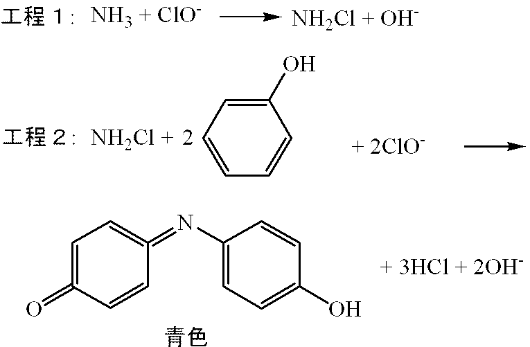
図1に示す気液相分離マイクロ流路を有するマイクロ流路チップを作製した。その模式平面図を図4に示す。被検物質測定マイクロ流路30には、酸化液導入マイクロ流路34と発色液導入マイクロ流路36を接続した。図4に示すマイクロ流路チップでは、アンモニアガスを溶解した捕集液を、気液相分離部分を通過させた後、一旦チップの外のチューブ(図4中、実線の矢印)に導き、チップ内の流路に再び導入して発色液及び酸化液と合流させ、それよりも下流のマイクロ流路内で反応させている。なお、図4は、マイクロ流路を形成した基板を示しており、「気液相分離部」として長方形で囲まれている部分にあるマイクロ流路はテフロン(登録商標)膜で被覆される。気液相分離マイクロ流路14の断面は、幅400μm、深さ80μmの半楕円形であり、これ以外のマイクロ流路の断面は、全て幅500μm、深さ150μmの半楕円形であった。ガス抽出マイクロ流路12の長さは、35cm、気液相分離マイクロ流路の長さは1cm、被検物質測定マイクロ流路30の長さは50cmであった。マイクロ流路チップは、図1に基づいて上記した通り、2枚のガラス基板の上面に、それぞれマイクロ流路を形成してこれらのガラス基板を積層することにより作製した。
気液相分離マイクロ流路14に代えて、直径2mmの空気孔をマイクロ流路の上部に設けたこと以外は、実施例1と同様なマイクロ流路チップを作製し、上記と同様に気液相分離の様子を顕微鏡観察した。その結果、気液相分離は、最大で連続8時間しか達成できなかった。また、気液相分離後の液の流れがスムーズでない場合が観察された。
Claims (14)
- 基板内に設けられたマイクロ流路と、該マイクロ流路の下流端に接続され、深さが10μm~100μmであり、上部が多孔性膜で被覆された気液相分離マイクロ流路とを具備するマイクロ流路チップ。
- 前記気液相分離マイクロ流路の深さが、前記マイクロ流路の深さよりも浅い請求項1記載のマイクロ流路チップ。
- 前記多孔性膜の平均孔径が0.1μm~2.0μmである請求項1又は2記載のマイクロ流路チップ。
- 前記多孔性膜が疎水性材料から成る請求項1ないし3のいずれか1項に記載のマイクロ流路チップ。
- 前記多孔性膜がポリテトラフロロエチレン膜である請求項4記載のマイクロ流路チップ。
- 前記マイクロ流路の幅が10μm~600μm、深さが5μm~300μmである請求項1ないし5のいずれか1項に記載のマイクロ流路チップ。
- 前記気液相分離マイクロ流路の長さが0.5cm~5cmである請求項1ないし6のいずれか1項に記載のマイクロ流路チップ。
- マイクロ流路内を流通する気相と液相から成る二相流であって液相流が前記マイクロ流路の周縁部を流通し、気相流がその内側を流通する二相流から、気相を排除して液相流にする気液相分離方法であって、請求項1ないし7のいずれか1項に記載のマイクロ流路チップ内の前記マイクロ流路に前記二相流を流通させ、前記気液相分離マイクロ流路に導き、該領域を流通させ、それによって前記気相流を前記多孔性膜を介して前記気液相分離マイクロ流路から外部に排出することを含む、気液相分離方法。
- 捕集液に可溶性の気体である被検物質を含む試料ガスを導入する試料ガス導入マイクロ流路と、
前記捕集液を導入する捕集液導入マイクロ流路と、
前記試料ガス導入マイクロ流路と前記捕集液導入マイクロ流路との合流部の下流に位置するガス抽出マイクロ流路であって、液相流が前記ガス抽出マイクロ流路の周縁部を流通し、気相流がその内側を流通する二相流が流通するガス抽出マイクロ流路と、
該ガス抽出マイクロ流路の下流端に接続され、その深さが10μm~100μmであり、上部が多孔性膜で被覆された気液相分離マイクロ流路と、
該気液相分離マイクロ流路の下流に接続され、該気液相分離マイクロ流路を通過することによって気相流が前記多孔性膜から排出された残りの液相流が流通し、該液相流中に含まれる前記被検物質を測定する被検物質測定マイクロ流路とを具備する、気体被検物質測定用マイクロ流路チップ。 - 前記いずれかのマイクロ流路に合流する少なくとも1つのマイクロ流路であって、前記被検物質の測定に必要な試薬を供給する試薬導入マイクロ流路をさらに具備する請求項9記載のマイクロ流路チップ。
- 請求項9又は10記載のマイクロ流路チップの前記試料ガス導入マイクロ流路に前記試料ガスを導入する工程と、
前記捕集液導入マイクロ流路に前記捕集液を導入する工程と、
前記試料ガスと前記捕集液とにより形成される前記二相流を前記ガス抽出マイクロ流路に流通させ、それによって前記試料ガス中の前記被検物質を前記捕集液中に捕集する工程と、
前記二相流を、前記気液相分離マイクロ流路に流通させ、それによって気相流を前記多孔性膜から外部に排出して液相流にする工程と、
得られた液相流中に含まれる前記被検物質を測定する工程とを含む、気体被検物質の測定方法。 - 前記気体被検物質がアンモニアである請求項11記載の方法。
- 前記マイクロ流路チップが、2個の前記試薬導入マイクロ流路をさらに具備する請求項9記載のマイクロ流路チップであり、一方の試薬導入マイクロ流路から発色液を導入し、もう一方の試薬導入マイクロ流路から酸化液を導入する、請求項12記載の方法。
- アンモニアの測定を、熱レンズ顕微鏡を用いて行う請求項13記載の方法。
Priority Applications (2)
| Application Number | Priority Date | Filing Date | Title |
|---|---|---|---|
| CN201080024006.2A CN102448602B (zh) | 2009-03-31 | 2010-03-31 | 微流路芯片及使用该微流路芯片的气液相分离方法 |
| US13/262,103 US8815604B2 (en) | 2009-03-31 | 2010-03-31 | Microchannel chip and method for gas-liquid phase separation using same |
Applications Claiming Priority (2)
| Application Number | Priority Date | Filing Date | Title |
|---|---|---|---|
| JP2009086805A JP5765722B2 (ja) | 2009-03-31 | 2009-03-31 | マイクロ流路チップ及びそれを用いた気液相分離方法 |
| JP2009-086805 | 2009-03-31 |
Publications (1)
| Publication Number | Publication Date |
|---|---|
| WO2010113997A1 true WO2010113997A1 (ja) | 2010-10-07 |
Family
ID=42828286
Family Applications (1)
| Application Number | Title | Priority Date | Filing Date |
|---|---|---|---|
| PCT/JP2010/055797 WO2010113997A1 (ja) | 2009-03-31 | 2010-03-31 | マイクロ流路チップ及びそれを用いた気液相分離方法 |
Country Status (4)
| Country | Link |
|---|---|
| US (1) | US8815604B2 (ja) |
| JP (1) | JP5765722B2 (ja) |
| CN (1) | CN102448602B (ja) |
| WO (1) | WO2010113997A1 (ja) |
Families Citing this family (12)
| Publication number | Priority date | Publication date | Assignee | Title |
|---|---|---|---|---|
| TW201422817A (zh) * | 2012-12-14 | 2014-06-16 | Ardic Instr Co | 生物感測晶片結構 |
| US20160349188A1 (en) * | 2014-01-14 | 2016-12-01 | Center National De La Recherche Scientifique (Cnrs) | Microfluidic device for analysis of flowing pollutants |
| US9920315B2 (en) | 2014-10-10 | 2018-03-20 | California Institute Of Technology | Methods and devices for micro-isolation, extraction, and/or analysis of microscale components in an array |
| JP6190352B2 (ja) * | 2014-12-19 | 2017-08-30 | 株式会社神戸製鋼所 | 流体流通装置及びその運転方法 |
| KR101768037B1 (ko) * | 2016-07-29 | 2017-08-14 | 한국과학기술원 | 필터 및 믹서를 구비하는 랩온어칩 |
| CN106629928B (zh) * | 2017-01-19 | 2018-10-02 | 中国石油大学(华东) | 一种带有疏水表面过滤壳的气水分离装置及其分离方法 |
| AU2018250317B2 (en) * | 2017-04-06 | 2023-05-11 | Sri International | Modular systems for performing multistep chemical reactions, and methods of using same |
| WO2018187717A1 (en) | 2017-04-06 | 2018-10-11 | Sri International | Continuous flow synthesis of ibuprofen |
| KR101910818B1 (ko) | 2017-06-02 | 2018-10-30 | 대한민국 | 유전자 판독용 랩온어칩 |
| CN108318394B (zh) * | 2018-05-09 | 2024-04-16 | 南京安控易创计算机科技有限公司 | 一种微流控分选测量可吸入颗粒物的方法及装置 |
| KR102185548B1 (ko) * | 2018-12-04 | 2020-12-03 | 한국기계연구원 | 기상시료의 유해인자 포집장치 |
| FR3104450B1 (fr) * | 2019-12-17 | 2022-06-03 | Univ Grenoble Alpes | Procédé de dégazage d’un fluide |
Citations (4)
| Publication number | Priority date | Publication date | Assignee | Title |
|---|---|---|---|---|
| JP2004113874A (ja) * | 2002-09-24 | 2004-04-15 | National Institute Of Advanced Industrial & Technology | マイクロ流路利用反応方法 |
| JP2005329364A (ja) * | 2004-05-21 | 2005-12-02 | Dkk Toa Corp | 気液反応ユニットおよび分析装置 |
| JP2006223118A (ja) * | 2005-02-15 | 2006-08-31 | Yamaha Corp | マイクロチップ |
| JP2008023418A (ja) * | 2006-07-18 | 2008-02-07 | Fuji Xerox Co Ltd | マイクロ流路デバイス |
-
2009
- 2009-03-31 JP JP2009086805A patent/JP5765722B2/ja active Active
-
2010
- 2010-03-31 WO PCT/JP2010/055797 patent/WO2010113997A1/ja active Application Filing
- 2010-03-31 US US13/262,103 patent/US8815604B2/en active Active
- 2010-03-31 CN CN201080024006.2A patent/CN102448602B/zh not_active Expired - Fee Related
Patent Citations (4)
| Publication number | Priority date | Publication date | Assignee | Title |
|---|---|---|---|---|
| JP2004113874A (ja) * | 2002-09-24 | 2004-04-15 | National Institute Of Advanced Industrial & Technology | マイクロ流路利用反応方法 |
| JP2005329364A (ja) * | 2004-05-21 | 2005-12-02 | Dkk Toa Corp | 気液反応ユニットおよび分析装置 |
| JP2006223118A (ja) * | 2005-02-15 | 2006-08-31 | Yamaha Corp | マイクロチップ |
| JP2008023418A (ja) * | 2006-07-18 | 2008-02-07 | Fuji Xerox Co Ltd | マイクロ流路デバイス |
Also Published As
| Publication number | Publication date |
|---|---|
| CN102448602A (zh) | 2012-05-09 |
| JP2010234313A (ja) | 2010-10-21 |
| JP5765722B2 (ja) | 2015-08-19 |
| US20120164743A1 (en) | 2012-06-28 |
| US8815604B2 (en) | 2014-08-26 |
| CN102448602B (zh) | 2014-11-26 |
Similar Documents
| Publication | Publication Date | Title |
|---|---|---|
| JP5765722B2 (ja) | マイクロ流路チップ及びそれを用いた気液相分離方法 | |
| Chen et al. | Microfluidic chip-based liquid–liquid extraction and preconcentration using a subnanoliter-droplet trapping technique | |
| RU2478431C2 (ru) | Микроструйное устройство и способ его изготовления и содержащий его сенсор | |
| EP1970110B1 (en) | Gas exchange system and method of controlling pressure-diference bubble transfer | |
| Létant et al. | Functionalized silicon membranes for selective bio-organism capture | |
| US20100098588A1 (en) | Apparatus for determining total organic carbon | |
| JP2005181095A (ja) | チップ、反応分析装置、反応分析方法 | |
| Kuswandi et al. | Optical fiber chemical sensing of Hg (II) ions in aqueous samples using a microfluidic device containing a selective tripodal chromoionophore-PVC film | |
| Gitlin et al. | Micro flow reactor chips with integrated luminescent chemosensors for spatially resolved on-line chemical reaction monitoring | |
| Xing et al. | Label-free biosensors based on in situ formed and functionalized microwires in microfluidic devices | |
| US8354069B2 (en) | Plug flow system for identification and authentication of markers | |
| Ghosh et al. | Enhancement of limit of detection by inducing coffee-ring effect in water quality monitoring microfluidic paper-based devices | |
| Moehlenbrock et al. | Use of microchip-based hydrodynamic focusing to measure the deformation-induced release of ATP from erythrocytes | |
| JP5425757B2 (ja) | 液体サンプルを処理するための装置 | |
| Toda et al. | Micro-gas analysis system μGAS comprising a microchannel scrubber and a micro-fluorescence detector for measurement of hydrogen sulfide | |
| Wang et al. | Pervaporation-flow injection determination of ammonia in the presence of surfactants | |
| Ranaweera et al. | Highly efficient preconcentration using anodically generated shrinking gas bubbles for per-and polyfluoroalkyl substances (PFAS) detection | |
| JP5781937B2 (ja) | 鉛の定量 | |
| WO2009125493A1 (ja) | 全有機体炭素測定装置 | |
| JP2009174891A (ja) | マイクロチップ | |
| US20150191772A1 (en) | Method of charging a test carrier and a test carrier | |
| JP2001074724A (ja) | 分子拡散を用いた反応法およびその装置 | |
| Ma et al. | Droplet microfluidic chip for precise monitoring of dynamic solution changes | |
| Baniya et al. | Lab‐on‐a‐chip for hydrogen sulphide detection—Part I: Sulphide separation from plasma sample | |
| CN211426258U (zh) | 一种光流控水体溶解氧探测器 |
Legal Events
| Date | Code | Title | Description |
|---|---|---|---|
| WWE | Wipo information: entry into national phase |
Ref document number: 201080024006.2 Country of ref document: CN |
|
| 121 | Ep: the epo has been informed by wipo that ep was designated in this application |
Ref document number: 10758768 Country of ref document: EP Kind code of ref document: A1 |
|
| NENP | Non-entry into the national phase |
Ref country code: DE |
|
| WWE | Wipo information: entry into national phase |
Ref document number: 13262103 Country of ref document: US |
|
| 122 | Ep: pct application non-entry in european phase |
Ref document number: 10758768 Country of ref document: EP Kind code of ref document: A1 |