WO2010113654A1 - 舶用エンジン制御システム - Google Patents
舶用エンジン制御システム Download PDFInfo
- Publication number
- WO2010113654A1 WO2010113654A1 PCT/JP2010/054638 JP2010054638W WO2010113654A1 WO 2010113654 A1 WO2010113654 A1 WO 2010113654A1 JP 2010054638 W JP2010054638 W JP 2010054638W WO 2010113654 A1 WO2010113654 A1 WO 2010113654A1
- Authority
- WO
- WIPO (PCT)
- Prior art keywords
- load torque
- control system
- marine engine
- propeller
- torque
- Prior art date
- Legal status (The legal status is an assumption and is not a legal conclusion. Google has not performed a legal analysis and makes no representation as to the accuracy of the status listed.)
- Ceased
Links
Images



Classifications
-
- F—MECHANICAL ENGINEERING; LIGHTING; HEATING; WEAPONS; BLASTING
- F02—COMBUSTION ENGINES; HOT-GAS OR COMBUSTION-PRODUCT ENGINE PLANTS
- F02D—CONTROLLING COMBUSTION ENGINES
- F02D31/00—Use of speed-sensing governors to control combustion engines, not otherwise provided for
- F02D31/001—Electric control of rotation speed
- F02D31/007—Electric control of rotation speed controlling fuel supply
-
- F—MECHANICAL ENGINEERING; LIGHTING; HEATING; WEAPONS; BLASTING
- F02—COMBUSTION ENGINES; HOT-GAS OR COMBUSTION-PRODUCT ENGINE PLANTS
- F02D—CONTROLLING COMBUSTION ENGINES
- F02D41/00—Electrical control of supply of combustible mixture or its constituents
- F02D41/02—Circuit arrangements for generating control signals
- F02D41/14—Introducing closed-loop corrections
- F02D41/1401—Introducing closed-loop corrections characterised by the control or regulation method
-
- F—MECHANICAL ENGINEERING; LIGHTING; HEATING; WEAPONS; BLASTING
- F02—COMBUSTION ENGINES; HOT-GAS OR COMBUSTION-PRODUCT ENGINE PLANTS
- F02D—CONTROLLING COMBUSTION ENGINES
- F02D41/00—Electrical control of supply of combustible mixture or its constituents
- F02D41/02—Circuit arrangements for generating control signals
- F02D41/14—Introducing closed-loop corrections
- F02D41/1401—Introducing closed-loop corrections characterised by the control or regulation method
- F02D2041/1409—Introducing closed-loop corrections characterised by the control or regulation method using at least a proportional, integral or derivative controller
-
- F—MECHANICAL ENGINEERING; LIGHTING; HEATING; WEAPONS; BLASTING
- F02—COMBUSTION ENGINES; HOT-GAS OR COMBUSTION-PRODUCT ENGINE PLANTS
- F02D—CONTROLLING COMBUSTION ENGINES
- F02D41/00—Electrical control of supply of combustible mixture or its constituents
- F02D41/02—Circuit arrangements for generating control signals
- F02D41/14—Introducing closed-loop corrections
- F02D41/1401—Introducing closed-loop corrections characterised by the control or regulation method
- F02D2041/141—Introducing closed-loop corrections characterised by the control or regulation method using a feed-forward control element
-
- F—MECHANICAL ENGINEERING; LIGHTING; HEATING; WEAPONS; BLASTING
- F02—COMBUSTION ENGINES; HOT-GAS OR COMBUSTION-PRODUCT ENGINE PLANTS
- F02D—CONTROLLING COMBUSTION ENGINES
- F02D2200/00—Input parameters for engine control
- F02D2200/02—Input parameters for engine control the parameters being related to the engine
- F02D2200/10—Parameters related to the engine output, e.g. engine torque or engine speed
- F02D2200/1002—Output torque
Definitions
- the present invention relates to a marine engine control system, and more particularly to a marine engine governor control.
- the present invention has been made in view of the above problems, and it is an object of the present invention to more quickly estimate the influence of disturbance on the propeller and to modify the governor control based on this to improve fuel efficiency.
- the marine engine control system of the present invention performs PID control of the fuel injection amount with the rotation speed of the main shaft or main engine as an input, and performs feedforward control for correcting the output from the PID control based on the load torque of the propeller. It is characterized by.
- the marine engine control system includes load torque detection means for detecting load torque, and the load torque detection means calculates the load torque based on, for example, distortion of the main shaft or based on horsepower and rotation speed.
- the influence of the disturbance on the propeller can be estimated more quickly, and based on this, the governor control can be modified to improve fuel efficiency.
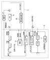
- FIG. 1 is a block diagram showing a configuration of an entire marine engine control system according to an embodiment of the present invention.
- the marine engine control system 10 of the present embodiment uses a hull 11, a main engine 12, a main shaft 13, a propeller 14 and the like as a control object S, and fuel is supplied to the main engine 12 from a fuel injection device (actuator) 15 of the control device C.
- the main shaft 13 connecting the main machine 12 and the propeller 14 is provided with a conventionally known rotation speed (angular speed) sensor (not shown) for detecting the actual rotation speed N E (or angular speed ⁇ E ) of the main shaft 13 or the main machine 12.
- the main shaft 13, the load torque detecting unit for detecting a load torque Q P of the propeller acting on the main shaft 13 (described later) is provided.
- Control system 10 which performs PID control spindle speed (or engine speed) as the rotation speed command (target value), the actual rotational speed N E detected in the main shaft 13 is fed back to the input side . That is, the PID operator 16 deviation between the rotation speed command and the actual rotation speed N E is input.
- the output from the PID calculation unit 16 is output to the fuel injection device 15 as a governor command, and the fuel supply amount to the main engine 12 is adjusted.
- a signal based on the load torque Q P from the load torque detecting unit is feedforward governor command is corrected to the output side of the PID computing unit 16.
- the propeller 14 because of the influence due to disturbance waves such, in this embodiment, monitors the load torque Q P, the correction signal corresponding to the change in the load torque Q P generated in the arithmetic unit 17, PID This is added to the governor command output from the calculation unit 16.
- FIG. 2 is a block diagram in which the control target S is modeled.
- N E angular velocity ⁇ E
- I moment of inertia
- t time
- Q E the main engine torque
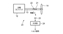
- the load torque detection unit 20 of the present embodiment includes a strain gauge 21 and a transmitter 22 mounted on the main shaft 13, and a receiver 23 and a measuring instrument 24 disposed on a fixed part on the hull side.
- a strain measurement value (strain signal) detected by the strain gauge 21 is transmitted to the receiver 23 via the transmitter 22, converted into a torque signal by the measuring instrument 24, and output to the computing unit 17. That is, since the torque is proportional to the strain, the strain measurements of received the arithmetic unit 17 (corresponding to the distorted signal) is multiplied by a predetermined coefficient to calculate the load torque Q P, the arithmetic unit 17 as a torque signal (FIG. 2 ).
- the load torque detector 30 of the first modification includes a strain gauge 21 attached to the main shaft 13, a slip ring 31 attached around the main shaft 13 and electrically connected to the strain gauge 21, and a brush that is in sliding contact with the slip ring 31. 32 and the measuring instrument 24 connected to the brush 32. That is, the strain signal detected by the strain gauge 21 is sent to the measuring instrument 24 via the slip ring 31 and the brush 32, and converted into a torque signal as in the first embodiment. Further, the torque signal generated in the measuring instrument 24 is output to the calculation unit 17. With the above configuration, the same effect as that of the above embodiment can be obtained also in the first modification.
- a horsepower meter 41 attached to the main shaft 13 near the propeller 14 is used instead of the strain gauge 21 of the above embodiment and the first modification.
- a torque calculation unit 42 is used instead of the measuring instrument 24.
- a horsepower signal from the horsepower meter 41 is sent to the torque calculator 42.
- the engine speed NE is input from the main machine 12 to the torque calculator 42.
- Hp (corresponding to substantially transmit horsepower DHP in this modification) is proportional to the rotational speed of the product between the torque, the torque calculation unit 42, horsepower (e.g. DHP) split predetermined coefficient by the engine speed N E (e.g. load torque Q P is obtained by applying a 1 / 2 ⁇ ).
- the calculated torque value is output to the computing unit 17 as a torque signal.
- the structure of the 3rd modification of a load torque detection part is demonstrated.
- the horsepower meter 41 of the second modified example is arranged on the main shaft 13 near the main machine 12, and the other configuration is the same as that of the third modified example.
- the torque calculator 42 divides the detected horsepower (BHP) by the engine speed N E , the transmission efficiency ⁇ T , and 2 ⁇ . Thus, torque is obtained.
- the third modification it is possible to obtain substantially the same effects as in the above embodiment and Modifications 1 and 2.
- the fluctuation of the propeller load torque due to waves or the like is detected, and this is fed forward to the rotation speed-based fuel supply PID control, thereby reducing the influence of the disturbance. It is possible to correct the main engine speed by estimating at an earlier stage. For example, sufficient responsiveness can be exhibited even with a disturbance having a period of about 10 seconds, and fuel consumption can be greatly improved.
Landscapes
- Engineering & Computer Science (AREA)
- Chemical & Material Sciences (AREA)
- Combustion & Propulsion (AREA)
- Mechanical Engineering (AREA)
- General Engineering & Computer Science (AREA)
- Combined Controls Of Internal Combustion Engines (AREA)
- Electrical Control Of Air Or Fuel Supplied To Internal-Combustion Engine (AREA)
- Control Of Vehicle Engines Or Engines For Specific Uses (AREA)
Abstract
回転数指令と実測された主軸13または主機12の回転数NEの偏差をPID演算部16に入力するとともに燃料噴射装置15から主機12へ供給される燃料の量をフィードバック制御する。プロペラ14に掛かる負荷トルクを検知して、PID演算部16から燃料噴射装置15に出力されるガバナ指令に修正を加える。
Description
本発明は、舶用エンジンの制御システムに関し、特に舶用エンジンのガバナ制御に関する。
舶用エンジンの制御では、設定された目標回転数と実回転数の差がなくなるようにPID制御が行われる。しかし、荒天時などには、プロペラによる負荷トルクが急激に変化するため通常の天候の下での航行を想定したゲインによるPID制御では、十分な応答性能が得られずオーバースピードによる機関の故障を招く恐れがある。このような問題に対しては、外乱によるプロペラ回転数の変動を予測してPID制御のゲインを変更する構成が提案されている(特許文献1)。
特開平8-200131号公報
しかし、特許文献1のようにPIDゲインを上げる構成では、ハンチングを起こし易くなったり燃費が悪化したりする。近年では、特に燃費向上が強く求められているため特許文献1の構成では十分ではなく、プロペラへの外乱に対してより高い応答性を備えたガバナ制御が求められている。
本発明は、上記問題に鑑みてなされたものであり、プロペラへの外乱の影響をより迅速に推定し、これに基づきガバナ制御に修正を加え燃費の向上を図ることを課題としている。
本発明の舶用エンジン制御システムは、主軸または主機の回転数を入力として燃料噴射量のPID制御を行うとともに、プロペラの負荷トルクに基づき前記PID制御からの出力に修正を加えるフィードフォワード制御を行うことを特徴としている。
舶用エンジン制御システムは、負荷トルクを検出するための負荷トルク検知手段を備え、負荷トルク検知手段は、例えば主軸の歪みに基づいて、あるいは馬力と回転数に基づいて負荷トルクを算出する。
本発明によれば、プロペラへの外乱の影響をより迅速に推定し、これに基づきガバナ制御に修正を加え燃費の向上を図ることができる。
10 舶用エンジン制御システム
11 船体
12 主機
13 主軸
14 プロペラ
15 ガバナ
16 PID演算部
17 演算部
20、30、40 負荷トルク検知部
21 歪ゲージ
22 送信機
23 受信機
24 計測器
31 スリップリング
32 ブラシ
41 馬力計
42 トルク計算部
C 制御装置
S 制御対象
11 船体
12 主機
13 主軸
14 プロペラ
15 ガバナ
16 PID演算部
17 演算部
20、30、40 負荷トルク検知部
21 歪ゲージ
22 送信機
23 受信機
24 計測器
31 スリップリング
32 ブラシ
41 馬力計
42 トルク計算部
C 制御装置
S 制御対象
以下、本発明の実施形態について添付図面を参照して説明する。
図1は、本発明の一実施形態である舶用エンジン制御システム全体の構成を示すブロック線図である。
図1は、本発明の一実施形態である舶用エンジン制御システム全体の構成を示すブロック線図である。
本実施形態の舶用エンジン制御システム10は、船体11、主機12、主軸13、プロペラ14などを制御対象Sとし、主機12には、制御装置Cの燃料噴射装置(アクチュエータ)15から燃料が供給される。主機12とプロペラ14を連結する主軸13には、主軸13または主機12の実回転数NE(または角速度ωE)を検出する従来周知の回転数(角速度)センサ(不図示)が設けられる。また、主軸13には、主軸13に掛かるプロペラの負荷トルクQPを検出する負荷トルク検出部(後述)が設けられる。
制御システム10は、主軸回転数(あるいはエンジン回転数)を回転数指令(目標値)としてPID制御を行うもので、主軸13において検出された実回転数NEは、入力側へとフィードバックされる。すなわち、PID演算部16には回転数指令と実回転数NEの間の偏差が入力される。PID演算部16からの出力は、ガバナ指令として燃料噴射装置15へ出力され、主機12への燃料供給量が調整される。
更に、本実施形態では、負荷トルク検出部からの負荷トルクQPに基づく信号がPID演算部16の出力側へとフィードフォワードされてガバナ指令が修正される。すなわち、プロペラ14には、波浪等の外乱による影響があるため、本実施形態では、負荷トルクQPをモニタし、負荷トルクQPの変動に対応した修正信号を演算部17において生成し、PID演算部16から出力されるガバナ指令に付加する。
すなわち本実施形態では、負荷トルクQPが主軸回転数NE(角速度ωE)の時間微分に比例することから、負荷トルクQPをモニタすることにより波浪による外乱が主軸回転数NEに大きく影響する前に外乱の影響を検知して出力に修正を加え、外乱による影響を低減している。
図2は制御対象Sをモデル化したブロック線図である。図2を参照して、負荷トルクのフィードフォワードによる効果について説明する。図2に示されるように、プロペラ周りの流体のプロペラへの流入速度(プロペラ流入速度)は、船速と波浪による流速とを加え合わせたもので、負荷トルクQPは、プロペラ流入速度とプロペラ回転数(主軸回転数)を入力としてプロペラのトルク特性に基づいて決定される。また、主軸13には、主機12による主機トルクQEから負荷トルクQPを差し引いたトルクQE-QPが作用する。
主軸13の回転数NE(角速度ωE)は、慣性モーメントをI、時間をt、主機トルクをQEとすると、NE=∫[(QE-QP)/I]dtとなる。すなわち、回転数NEは、トルクを積分(1/s)したものなのでトルク変動のほうが回転数の変化よりも外乱に対する応答性が高い。したがって、負荷トルクQPをモニタしてフィードフォワード制御を行うことにより波浪(外乱)の影響をより有効に低減できる。
次に図3を参照して、本実施形態の負荷トルク検知部の構成について説明する。本実施形態の負荷トルク検知部20は、主軸13に装着された歪ゲージ21および送信機22と、船体側の固定部に配置された受信機23および計測器24から構成される。歪ゲージ21において検出された歪の測定値(歪信号)は、送信機22を介して受信機23に送信され、計測器24において、トルク信号に変換され演算部17へと出力される。すなわち、トルクは歪に比例するため、演算部17では受信した歪の測定値(歪信号に対応)に所定の係数を掛けて負荷トルクQPを算出し、トルク信号として演算部17(図2)へ出力する。
次に図4を参照して、本実施形態の負荷トルク検知部20の第1変形例の構成について説明する。第1変形例の負荷トルク検知部30は、主軸13に装着された歪ゲージ21、主軸13の周囲に装着され歪ゲージ21に電気的に接続されたスリップリング31、スリップリング31と摺接するブラシ32、ブラシ32に接続された計測器24から構成される。すなわち、歪ゲージ21において検出された歪信号は、スリップリング31、ブラシ32を介して計測器24に送られ、第1実施形態と同様にトルク信号に変換される。また計測器24において生成されたトルク信号は、演算部17へと出力される。以上の構成により第1変形例においても上記実施形態と同様の効果を得ることができる。
次に図5を参照して、負荷トルク検知部の第2変形例の構成について説明する。第2変形例の負荷トルク検知部40では、上記実施形態、第1変形例の歪ゲージ21に替えてプロペラ14近くの主軸13に装着された馬力計41が用いられる。また、第2変形例では計測器24に替えてトルク計算部42が用いられる。
第2変形例においては、馬力計41からの馬力信号がトルク計算部42に送られる。トルク計算部42には、馬力計41からの馬力信号のほか主機12からエンジン回転数NEが入力される。馬力(本変形例では略伝達馬力DHPに対応)は、トルクと回転数の積に比例するため、トルク計算部42では、馬力(例えばDHP)をエンジン回転数NEで割り所定の係数(例えば1/2π)を掛けることにより負荷トルクQPが求められる。算出されたトルクの値はトルク信号として演算部17へ出力される。
次に図6を参照して、負荷トルク検知部の第3変形例の構成について説明する。第3変形例は、第2変形例の馬力計41を主機12近くの主軸13に配置したもので、その他の構成は第3変形例と同様である。第3変形例では、検出される馬力が略制動馬力BHPに対応するため、トルク計算部42では、検出された馬力(BHP)をエンジン回転数NE、伝達効率ηT、および2πで割ることによりトルクが求められる。以上のように第3変形例においても、上記実施形態および変形例1、2と略同様の効果を得ることができる。
以上のように、本実施形態の構成によれば、波浪等(外乱)によるプロペラ負荷トルクの変動を検知し、これを回転数ベースの燃料供給PID制御にフィードフォワードすることにより、外乱の影響をより早い段階で推測して主機回転数の修正を行うことが可能となり、例えば10秒程の周期の外乱に対しても十分な応答性を示し、燃費を大きく改善することができる。
Claims (4)
- 主軸または主機の回転数を入力として燃料噴射量のPID制御を行うとともに、プロペラの負荷トルクに基づき前記PID制御からの出力に修正を加えるフィードフォワード制御を行うことを特徴とする舶用エンジン制御システム。
- 前記負荷トルクを検出するための負荷トルク検知手段を備えることを特徴とする請求項1に記載の舶用エンジン制御システム。
- 前記負荷トルク検知手段が、前記主軸の歪みに基づいて負荷トルクを算出することを特徴とする請求項2に記載の舶用エンジン制御システム。
- 前記負荷トルク検知手段が、馬力と前記回転数に基づいて負荷トルクを算出することを特徴とする請求項2に記載の舶用エンジン制御システム。
Applications Claiming Priority (2)
| Application Number | Priority Date | Filing Date | Title |
|---|---|---|---|
| JP2009-087865 | 2009-03-31 | ||
| JP2009087865A JP2010236513A (ja) | 2009-03-31 | 2009-03-31 | 舶用エンジン制御システム |
Publications (1)
| Publication Number | Publication Date |
|---|---|
| WO2010113654A1 true WO2010113654A1 (ja) | 2010-10-07 |
Family
ID=42827951
Family Applications (1)
| Application Number | Title | Priority Date | Filing Date |
|---|---|---|---|
| PCT/JP2010/054638 Ceased WO2010113654A1 (ja) | 2009-03-31 | 2010-03-18 | 舶用エンジン制御システム |
Country Status (3)
| Country | Link |
|---|---|
| JP (1) | JP2010236513A (ja) |
| TW (1) | TW201035441A (ja) |
| WO (1) | WO2010113654A1 (ja) |
Cited By (1)
| Publication number | Priority date | Publication date | Assignee | Title |
|---|---|---|---|---|
| EP4446575A4 (en) * | 2022-01-26 | 2025-04-02 | Mitsubishi Heavy Industries Engine & Turbocharger, Ltd. | Engine control device, engine control system, and engine control program |
Families Citing this family (2)
| Publication number | Priority date | Publication date | Assignee | Title |
|---|---|---|---|---|
| JP5084788B2 (ja) * | 2009-06-12 | 2012-11-28 | 日本郵船株式会社 | 船舶の燃料調節装置 |
| WO2020235689A1 (ja) * | 2019-05-22 | 2020-11-26 | 国立研究開発法人 海上・港湾・航空技術研究所 | エンジン制御方法、エンジン制御システム、及び船舶 |
Citations (3)
| Publication number | Priority date | Publication date | Assignee | Title |
|---|---|---|---|---|
| JPS58143144A (ja) * | 1982-02-17 | 1983-08-25 | Mitsubishi Heavy Ind Ltd | 舶用エンジンの制御装置 |
| JPH08169324A (ja) * | 1994-12-16 | 1996-07-02 | Mitsubishi Electric Corp | 車両制御用軸トルク検出装置 |
| JPH09158761A (ja) * | 1995-12-11 | 1997-06-17 | Mitsubishi Heavy Ind Ltd | 機関の燃料制御装置 |
-
2009
- 2009-03-31 JP JP2009087865A patent/JP2010236513A/ja active Pending
-
2010
- 2010-03-18 WO PCT/JP2010/054638 patent/WO2010113654A1/ja not_active Ceased
- 2010-03-24 TW TW99108653A patent/TW201035441A/zh unknown
Patent Citations (3)
| Publication number | Priority date | Publication date | Assignee | Title |
|---|---|---|---|---|
| JPS58143144A (ja) * | 1982-02-17 | 1983-08-25 | Mitsubishi Heavy Ind Ltd | 舶用エンジンの制御装置 |
| JPH08169324A (ja) * | 1994-12-16 | 1996-07-02 | Mitsubishi Electric Corp | 車両制御用軸トルク検出装置 |
| JPH09158761A (ja) * | 1995-12-11 | 1997-06-17 | Mitsubishi Heavy Ind Ltd | 機関の燃料制御装置 |
Cited By (2)
| Publication number | Priority date | Publication date | Assignee | Title |
|---|---|---|---|---|
| EP4446575A4 (en) * | 2022-01-26 | 2025-04-02 | Mitsubishi Heavy Industries Engine & Turbocharger, Ltd. | Engine control device, engine control system, and engine control program |
| US12378928B2 (en) | 2022-01-26 | 2025-08-05 | Mitsubishi Heavy Industries Engine & Turbocharger, Ltd. | Engine control device, engine control system, and engine control program |
Also Published As
| Publication number | Publication date |
|---|---|
| JP2010236513A (ja) | 2010-10-21 |
| TW201035441A (en) | 2010-10-01 |
Similar Documents
| Publication | Publication Date | Title |
|---|---|---|
| JP4854756B2 (ja) | 舶用エンジン制御システム | |
| JP5296753B2 (ja) | 舶用エンジン制御システム及び方法 | |
| US7877174B2 (en) | Watercraft speed control device | |
| JP5830309B2 (ja) | 船舶の推進装置 | |
| JP5042977B2 (ja) | 可変ピッチプロペラの翼角制御方法および装置 | |
| WO2010113654A1 (ja) | 舶用エンジン制御システム | |
| US20080003899A1 (en) | Watercraft speed control device | |
| KR20170052339A (ko) | 고풍속 고난류에서의 풍력발전기 피치제어 방법 | |
| JP6047923B2 (ja) | 可変ピッチプロペラ制御装置および可変ピッチプロペラ制御装置を搭載した船舶ならびに可変ピッチプロペラ制御方法 | |
| KR101266024B1 (ko) | 선박의 엔진 제어 장치 및 방법 | |
| WO2010113655A1 (ja) | 舶用エンジン制御システム | |
| KR101229816B1 (ko) | 선박용 엔진 제어 장치 및 방법 | |
| CN108202852A (zh) | 在双轴船中通过实时震动信息和调节螺旋桨的旋转角度而降低脉动压力的方法 | |
| JP6907139B2 (ja) | 舶用主機関の制御システム | |
| US8145372B2 (en) | Watercraft speed control device | |
| WO2020235689A1 (ja) | エンジン制御方法、エンジン制御システム、及び船舶 | |
| JP5084788B2 (ja) | 船舶の燃料調節装置 | |
| KR20220028077A (ko) | 선박의 추진 파워 출력을 제어하기 위한 방법 및 시스템 | |
| JP2011214472A (ja) | 舶用エンジンの制御装置および方法 | |
| JP4888867B2 (ja) | 舶用エンジンのガバナ制御装置および制御方法 | |
| JPS5951473B2 (ja) | 可変ピツチプロペラによる自動船速制御方法 |
Legal Events
| Date | Code | Title | Description |
|---|---|---|---|
| 121 | Ep: the epo has been informed by wipo that ep was designated in this application |
Ref document number: 10758430 Country of ref document: EP Kind code of ref document: A1 |
|
| NENP | Non-entry into the national phase |
Ref country code: DE |
|
| 122 | Ep: pct application non-entry in european phase |
Ref document number: 10758430 Country of ref document: EP Kind code of ref document: A1 |