WO2010113388A1 - 廃棄針用回収容器及び廃棄針用回収部品 - Google Patents
廃棄針用回収容器及び廃棄針用回収部品 Download PDFInfo
- Publication number
- WO2010113388A1 WO2010113388A1 PCT/JP2010/001483 JP2010001483W WO2010113388A1 WO 2010113388 A1 WO2010113388 A1 WO 2010113388A1 JP 2010001483 W JP2010001483 W JP 2010001483W WO 2010113388 A1 WO2010113388 A1 WO 2010113388A1
- Authority
- WO
- WIPO (PCT)
- Prior art keywords
- hole
- holding body
- gripping
- container
- waste
- Prior art date
- Legal status (The legal status is an assumption and is not a legal conclusion. Google has not performed a legal analysis and makes no representation as to the accuracy of the status listed.)
- Ceased
Links
Images










Classifications
-
- A—HUMAN NECESSITIES
- A61—MEDICAL OR VETERINARY SCIENCE; HYGIENE
- A61M—DEVICES FOR INTRODUCING MEDIA INTO, OR ONTO, THE BODY; DEVICES FOR TRANSDUCING BODY MEDIA OR FOR TAKING MEDIA FROM THE BODY; DEVICES FOR PRODUCING OR ENDING SLEEP OR STUPOR
- A61M5/00—Devices for bringing media into the body in a subcutaneous, intra-vascular or intramuscular way; Accessories therefor, e.g. filling or cleaning devices, arm-rests
- A61M5/178—Syringes
- A61M5/31—Details
- A61M5/32—Needles; Details of needles pertaining to their connection with syringe or hub; Accessories for bringing the needle into, or holding the needle on, the body; Devices for protection of needles
- A61M5/3205—Apparatus for removing or disposing of used needles or syringes, e.g. containers; Means for protection against accidental injuries from used needles
-
- A—HUMAN NECESSITIES
- A61—MEDICAL OR VETERINARY SCIENCE; HYGIENE
- A61M—DEVICES FOR INTRODUCING MEDIA INTO, OR ONTO, THE BODY; DEVICES FOR TRANSDUCING BODY MEDIA OR FOR TAKING MEDIA FROM THE BODY; DEVICES FOR PRODUCING OR ENDING SLEEP OR STUPOR
- A61M5/00—Devices for bringing media into the body in a subcutaneous, intra-vascular or intramuscular way; Accessories therefor, e.g. filling or cleaning devices, arm-rests
- A61M5/178—Syringes
- A61M5/31—Details
- A61M5/32—Needles; Details of needles pertaining to their connection with syringe or hub; Accessories for bringing the needle into, or holding the needle on, the body; Devices for protection of needles
- A61M5/3205—Apparatus for removing or disposing of used needles or syringes, e.g. containers; Means for protection against accidental injuries from used needles
- A61M2005/3208—Apparatus for removing or disposing of used needles or syringes, e.g. containers; Means for protection against accidental injuries from used needles by application of rotational movement to the needle hub, e.g. by use of electrically driven toothed wheels
Definitions
- the present invention relates to a waste needle collection container and a waste needle collection component.
- the user when removing a used needle unit, the user can easily remove it without touching the used needle unit directly and without using a complicated instrument. It aims at providing the collection container for waste needles, and the collection parts for waste needles.
- the waste needle collection container collects the injection needle portion screwed into the tip of the syringe body via the holding body.
- the collection container for waste needles includes a container main body and an opening formed on the upper surface of the container main body and having an insertion hole into which the holding body is inserted.
- the opening includes a gripping mechanism that grips the holding body, and a motion conversion mechanism that rotates the gripping mechanism in accordance with a linear motion of the gripping mechanism in a hole direction in which the insertion hole extends.
- the holding body inserted into the insertion hole is separated from the syringe body by being moved in the hole direction.
- the gripping mechanism is provided at a position where the linear motion is performed in a trajectory passing through the center of gravity of the waste needle collection container.
- the gripping mechanism has a meshing portion that meshes with the unevenness provided on the holding body and prohibits relative rotation of the holding body with respect to the gripping mechanism.
- the waste needle collection container further includes a biasing mechanism that biases the gripping mechanism upward.
- the separation portion having the opening is detachably attached to the container body.
- the container body has a disposal port for discarding the separated injection needle portion and an opening / closing member for opening and closing the disposal port.
- the container main body further includes a recovery mechanism for recovering the injection needle portion fitted to the tip of the syringe main body via a holding body.
- the waste needle recovery part is used in a waste needle recovery container for recovering an injection needle screwed into a distal end of a syringe body via a holding body.
- the waste needle recovery part includes a connection mechanism connected to the container body of the waste needle recovery container, and an opening formed with an insertion hole into which the holding body is inserted.
- the opening includes a gripping mechanism that grips the holding body, and a motion conversion mechanism that rotates the gripping mechanism in accordance with a linear motion of the gripping mechanism in a hole direction in which the insertion hole extends.
- the motion conversion mechanism moves the gripping mechanism in one rotational direction while bringing the gripping mechanism into a holding body gripping state for gripping the holding body with a linear motion in one of the hole directions.
- Rotate The opening portion moves the holding body in the one rotation direction while causing the holding mechanism to release the holding body without holding the holding body in accordance with a linear motion in the other movement direction in the hole direction.
- Another motion conversion mechanism for rotating the motor. The holder inserted into the insertion hole is separated from the syringe body by being moved in one movement direction and the other movement direction in the hole direction.
- the movement converting mechanism further rotates in the one rotation direction together with the gripping mechanism in accordance with a linear movement in the one movement direction in the hole direction.
- the movement converting mechanism rotates in the other rotation direction together with the gripping mechanism in accordance with the linear movement in the other movement direction.
- the another motion conversion mechanism rotates the holding body based on the rotation of the motion conversion mechanism in the other rotation direction in accordance with the linear motion in the other movement direction in the hole direction.
- the another motion conversion mechanism is a first planetary gear that meshes with the internal gear and an internal gear that is centered on a rotation shaft that rotates the motion conversion mechanism and that does not rotate around the rotation shaft.
- a first planetary gear that revolves and rotates around the rotation axis in accordance with rotation of the motion conversion mechanism; and a second planetary gear that selectively meshes with the first planetary gear, wherein the motion conversion mechanism includes: A second planetary gear that revolves and rotates around the rotation shaft according to rotation, a meshed state in which the first planetary gear and the second planetary gear mesh with each other, and a meshed release state in which these mesh with each other.
- a meshing switching mechanism for switching and a roller portion that is relatively non-rotatably coupled to the output shaft of the second planetary gear, wherein the side surface of the roller portion contacts the side surface of the holding body inserted into the insertion hole
- the mesh switching mechanism is in the mesh release state when the motion conversion mechanism is linearly moving in one of the hole directions, and the motion conversion mechanism is in the other of the hole directions.
- the mesh switching mechanism is a shaft that connects the roller unit and the second planetary gear so as not to be relatively rotatable, and is a shaft that is held by the motion conversion mechanism so as to be movable in the hole direction, and the shaft A first urging mechanism for urging the other movement direction in the hole direction, and the shaft when the motion conversion mechanism linearly moves in the one movement direction in the hole direction. And a second urging mechanism for moving the first planetary gear and the second planetary gear into the mesh release state.
- the another motion conversion mechanism includes a guide mechanism that guides the internal gear so that the internal gear does not rotate around the rotation axis and can be translated in the hole direction.
- the opening further includes a flexible sheet provided in the vicinity of the insertion hole and having a hole in the center.
- the motion conversion mechanism moves the gripping mechanism in one rotational direction while bringing the gripping mechanism into a holding body gripping state for gripping the holding body with a linear motion in one of the hole directions.
- Rotate The opening portion moves the holding body in the one rotation direction while causing the holding mechanism to release the holding body without holding the holding body in accordance with a linear motion in the other movement direction in the hole direction.
- Another motion conversion mechanism for rotating the motor The holding body inserted into the insertion hole is separated from the syringe body by being moved in one movement direction and the other movement direction in the hole direction.
- the opening includes a gripping mechanism that grips the holding body, and a motion conversion mechanism that rotates the gripping mechanism in accordance with a linear motion in a hole direction in which the insertion hole of the gripping mechanism extends. Therefore, the holding body inserted into the insertion hole is separated from the syringe body by being moved in the direction of the hole.
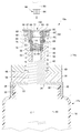
- FIG. 5 is another partial cross-sectional view of the waste needle recovery container and the waste needle recovery part shown in FIG. 1.
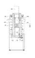
- FIG. 10 is a partial cross-sectional view illustrating a procedure for using the waste needle recovery container and the waste needle recovery part subsequent to FIG. 9. It is the front view which made a part of another collection container for waste needles and a collection part for waste needles of the present invention into a section.
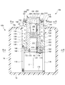
- FIG. 14 is a partial cross-sectional view of the waste needle recovery container and the waste needle recovery part shown in FIG. 13 cut at 14-14.
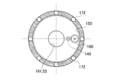
- FIG. 15 is a partial cross-sectional view of the waste needle recovery container and the waste needle recovery part shown in FIG. It is a fragmentary sectional view which shows the use procedure of the collection container for waste needles and the collection parts for waste needles shown in FIG. FIG.
- FIG. 17 is a partial cross-sectional view illustrating a procedure for using the waste needle recovery container and the waste needle recovery part subsequent to FIG. 16.
- FIG. 18 is a partial cross-sectional view showing a procedure for using the waste needle recovery container and the waste needle recovery part following FIG. 17.
- FIGS. An embodiment for carrying out the present invention will be described with reference to FIGS. This is merely an example, and the technical scope of the present invention is not limited to this.
- upward refers to the direction of arrow X1 in FIG. 1
- downward refers to the direction of arrow X2.
- an upper side from a certain position is referred to as “upper side”
- a lower side from a certain position is referred to as “lower side”.
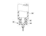
- the waste needle collection container 10 is used to collect a syringe needle portion 96 screwed into a distal end 92 of a syringe main body 90 shown in FIG.
- the waste needle collection container 10 includes a container body 12 and an opening 14. Further, the waste needle collection container 10 includes a lid 114 that covers the opening 14.
- the container main body 12 has a column-shaped side portion 16, a bottom portion 18 that covers the lower portion of the side portion 16, and a cylindrical mouth portion 20 (see FIG. 9) formed in the upper portion 16 a of the side portion 16.
- the surface is a substantially U-shaped container.
- the side portion 16 has a cylindrical side surface shape, but may have other shapes, for example, a quadrangular prism side surface shape, an octagonal side surface shape, an elliptical cylinder side surface shape, etc., or a truncated cone shape or a truncated pyramid shape. There may be.
- the bottom 18 has a substantially disk-shaped bottom, for example.
- the bottom portion 18 may further include a non-slip portion 22 disposed below the bottom.
- the anti-slip part 22 is formed of a material that makes it difficult for the installation surface F such as the upper surface of the desk and the anti-slip part 22 to move relative to each other, for example, an elastic body such as rubber. .
- the anti-skid part 22 has an effect of preventing the anti-skid part 22 and the installation surface F from sliding with each other by a rotational force that rotates around the columnar central axis C of the side part 16.
- the side part 16 is separated from the syringe main body 90 and has a size capable of accommodating a plurality of collected injection needle parts 96.
- the side portion 16 further includes a disposal port portion 24 for discarding the plurality of injection needle portions 96 accommodated therein, and an opening / closing member 26 such as a cap for opening and closing the disposal port portion 24.
- the disposal port portion 24 is formed in a cylindrical shape having a central axis extending in a direction parallel to the central axis C of the side portion 16, but is not limited thereto, and is formed in a cylindrical shape having a central axis extending in an arbitrary direction. It may be formed.
- the discard port portion 24 has, for example, a cylindrical shape, and a disc-shaped flange portion 24 a is formed at the upper end portion of the discard port portion 24. Accordingly, the groove 24b is formed by the flange 24a and the upper portion 16a.
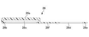
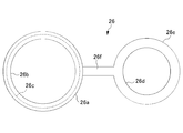
- the opening / closing member 26 includes, for example, a disk-shaped base portion 26 a that can cover the disposal port portion 24, and a base portion that extends from the periphery of one surface of the base portion 26 a.
- 26a includes a flange portion 26b extending toward the center of 26a, a plate-like hinge portion 26f extending from the base portion 26a, and a disc portion 26e formed on the hinge portion 26f.
- the opening / closing member 26 is preferably formed of the same material as the container body 12, for example.
- the collar part 26b and the base part 26a form a groove part 26c.
- a hole 26d having a diameter slightly larger than the diameter of the valley of the groove 24b is formed in the disk portion 26e (see FIG. 2).
- the diameter of the trough of the groove 26c is substantially the same as the diameter of the tip of the flange 24a.
- the hole 26 d of the disk part 26 e is fitted in the groove part 24 b of the disposal port part 24.
- the opening / closing member 26 closes the disposal port portion 24 by fitting the groove portion 26c to the flange portion 24a in a state where the hinge portion 26f is bent. Therefore, when the opening / closing member 26 is necessary, the opening / closing member 26 and the disposal port portion 24 are elastically deformed by pulling the opening / closing member 26 upward or by fitting the flange portion 24a to the groove portion 26c. Then, the disposal port 24 is opened or closed.
- a hook for removing the injection needle portion 99 fitted to the syringe main body 98 of the syringe for insulin shown in FIG. 8 from the syringe main body 98 with one hand is disposed inside the disposal port portion 24.
- the part 25 may be formed.
- the hook portion 25 is preferably formed of the same material as the disposal port portion 24.
- the hook portion 25 includes, for example, a base portion 25a that extends inward from about half of the inner peripheral surface of the disposal port portion 24, and an extension that extends from both ends of the base portion 25a to the center of the disposal port portion 24.
- the existing portion 25C is provided with a slit forming portion 25d that forms a cross-shaped slit 25b in the vicinity of the center of the disposal port portion 24 at the end of the extending portion 25C.
- the insulin syringe includes a syringe main body 98 and an injection needle portion 99 fitted to the tip 98 a of the syringe main body 98.
- the injection needle portion 99 includes a cylindrical portion 99b that fits the distal end 98a of the syringe main body 98, and a flange portion 99a that is formed at an end portion of the cylindrical portion 99b.
- the outer diameter of the cylindrical portion 99b is preferably slightly smaller than the width of the slit 25b.
- the outer diameter of the flange 99a is preferably slightly larger than the width of the slit 25b.
- the mouth portion 20 is formed in a cylindrical shape on the upper portion 16 a so as to coincide with the columnar center axis C of the side portion 16.
- a male screw 28 is formed on the cylindrical outer peripheral surface of the mouth portion 20. The rotation axis of the male screw 28 substantially coincides with the cylindrical center axis C of the side portion 16.
- the side part 16, the upper part 16 a, the bottom part 18, and the mouth part 20 of the container body 12 are all formed of a resin material such as plastic, in particular, a visible resin material. However, it may be formed of a metal material such as stainless steel or steel.
- the opening 14 is located on the upper surface of the container body 12.
- the opening portion 14 has a separation portion 32 in which a female screw 30 that is screwed into the male screw 28 of the mouth portion 20 of the container body 12 is formed.
- the separation part 32 has a cylindrical shape and has a recess that opens downward.
- a female screw 30 is formed on the inner peripheral surface of the recess so that the central axis of the female screw 30 coincides with the cylindrical central axis C of the side portion 16.
- a cylindrical convex portion 32a is formed on the upper surface of the separation portion 32, and a lower end of a compression coil spring 54 described later is disposed.
- the compression coil spring 54 is an example, and is not limited to this as long as it is an urging mechanism.
- the separation part 32 is formed with a cylindrical through-hole 34 that penetrates the bottom 33 of the recess and the protrusion 32a on the upper surface of the separation part 32.
- the central axis of the through hole 34 coincides with the cylindrical central axis C of the side portion 16. Accordingly, when the separating portion 32 is rotated with respect to the container body 12 so as to rotate around the central axis C, the male screw 28 and the female screw 30 can be unscrewed. As a result, the opening part 14 has a structure separated from the container main body 12.
- a bearing 50 that is screwed into the ball spline shaft 48 is assembled to the bottom 33 of the separation unit 32 by a known mounting mechanism such as a bolt.
- the bearing 50 is attached to the bottom 33 of the separation portion 32 so that the axis of the ball spline shaft 48 coincides with the central axis C, for example.
- the ball spline shaft 48 and the bearing 50 are given as an example of a mechanism for converting a rotational motion into a linear motion, and may be, for example, a trapezoidal screw, a general male screw, or a female screw.
- the material is demonstrated as a metal, if it can exhibit the function which converts a rotational motion into a linear motion, it will not be limited, For example, resin may be sufficient.
- the ball spline shaft 48 rotates around the axis of the ball spline shaft 48, the ball spline shaft 48 moves while rotating in the direction in which the axis of the ball spline shaft 48 extends with respect to the bearing 50.
- the ball spline shaft 48 and the bearing 50 have a structure that must be rotated around the axis of the ball spline shaft 48 in order for the ball spline shaft 48 to move in the direction in which the axis of the ball spline shaft 48 extends.
- the ball spline shaft 48 and the bearing 50 function as a motion conversion mechanism that rotates the ball spline shaft 48 as the ball spline shaft 48 moves in the direction in which the central axis C extends.
- the central axis C passes through the center of gravity of the waste needle collection container 10
- the axis of the ball spline shaft 48 passes through the center of gravity of the waste needle collection container 10.
- the ball spline shaft 48 has a through hole 52 that passes through the center of the ball spline shaft 48 in the direction in which the ball spline shaft 48 extends.
- a recess 56 is formed in the upper end portion of the ball spline shaft 48.
- the inner peripheral side surface of the recess 56 has a cylindrical shape.
- the opening 14 has an inner gripping portion 60 that holds the cylindrical side surface of the holding body 94 and an outer gripping portion 62 into which the inner gripping portion 60 is inserted.
- the inner gripper 60 and the outer gripper 62 act as a gripping mechanism 64 that grips the holding body 94 in cooperation.
- the lower end portion of the outer gripping portion 62 is fitted into the concave portion 56 of the ball spline shaft 48 so as not to be relatively rotatable.
- the outer gripping portion 62 has a cylindrical shape, and includes a recess 66 that is open on the upper side, and a through hole 68 formed in the bottom of the recess 66.
- the vicinity of the opening of the recess 66 is formed into a taper that spreads outward, such as a truncated conical side surface. This taper acts as a guide mechanism that guides the lower end of the inner gripper 60 to the recess 66.
- the center of the inner peripheral surface of the recess 66 and the center of the through hole 68 are both located on the extension line of the central axis C.
- a compression coil spring 70 that is an example of an urging mechanism is arranged in a compressed state in the recess 66 of the outer gripping portion 62.
- the compression coil spring 70 preferably has a spring constant smaller than that of the compression coil spring 54.
- a spacer 72 is slidably disposed on the upper side of the compression coil spring 70.
- the spacer 72 has a cylindrical shape.
- two long holes 74 that are long in the direction in which the cylindrical axis of the spacer 72 extends are formed on the opposite side surfaces of the spacer 72.
- the inner gripper 60 is disposed on the upper side of the spacer 72 so that the lower end of the inner gripper 60 contacts the upper side of the spacer 72.
- An upper spring receiving member 78 is disposed on the upper end of the compression coil spring 70.
- the upper spring receiving member 78 has a cylindrical shape.
- a recess 76 is formed at the lower end of the upper spring receiving member 78.
- the recess 76 has an inner peripheral surface with a diameter slightly larger than the outer diameter of the compression coil spring 54.
- a recess 80 is also formed on the upper side of the upper spring receiving member 78.
- the recess 80 holds the bearing 82, for example.
- a bearing is mentioned, but the present invention is not limited to this, and any configuration that reduces frictional resistance may be used.
- an oilless bearing or a bush may be used, and the material is stainless steel or resin. May be.
- the upper spring receiving member 78 is formed with a through hole 84 that penetrates the bottom surface of the recess 76 and the bottom surface of the recess 80. The center of the through hole 84 is located on an extension line of the central axis C.
- a cover 86 is disposed at the upper end of the inner gripping portion 60.
- the cover 86 includes a disk portion 85 and a cylindrical portion 87 formed on the lower side of the disk portion 85.
- a through hole 88 is formed in the center of the disk portion.
- the inner diameter of the tubular portion 87 is larger than the outer diameter of the inner gripping portion 60 and the outer gripping portion 62.
- the outer diameter of the tubular portion 87 is the inner diameter of the compression coil spring 54, the inner diameter of the through hole 84, and the bearing 82. Smaller than any of the inner diameters.
- the inner gripping portion 60 has a through hole 61 that penetrates in the vertical direction.
- the through hole 61 has a diameter slightly larger than the outer diameter of the holding body 94.
- a slit 63 is formed on the inner side surface of the through hole 61 to act as a clearance when the outer diameter of the inner gripping portion 60 is reduced.
- a meshing portion (not shown) is formed that meshes with the unevenness provided on the holding body 94 so that the holding body 94 and the inner gripping portion 60 are not relatively rotatable.
- the inner gripping portion 60 has a structure in which an upper end portion has a cylindrical shape, a central portion has a tapered shape and a lower end portion has a cylindrical shape.
- the upper end portion has substantially the same diameter as the outer diameter of the outer gripping portion 62.
- the lower end portion has a diameter that is substantially the same as or slightly smaller than the inner diameter of the outer gripping portion 62.
- a through-hole is formed in the tubular portion 87 of the cover 86, and a female screw hole is formed in the outer grip portion 62.
- a set screw 83 is screwed into the female screw hole through the through hole of the tubular portion 87. Therefore, the ball spline shaft 48 is assembled so as not to move relative to the cover 86 via the outer gripping portion 62 and the set screw 83.
- the compression coil spring 54 is arranged in a state where the compression coil spring 54 is slightly compressed, and its lower end is disposed in the recess 42 of the lower spring receiving member 40 and its upper end is disposed in the recess 76 of the upper spring receiving member 78. Therefore, the upper spring receiving member 78 is urged to always move upward. This biasing force is transmitted to the disk portion 85 of the cover 86 via the upper spring receiving member 78 and the bearing 82.
- the tip of the set screw 83 protrudes inward from the inner peripheral surface of the concave portion 66 of the outer gripping portion 62 and is inserted into the long hole 74 of the spacer 72.
- the spacer 72 can slide in the vertical direction by the length of the long hole 74 on the inner peripheral surface of the concave portion 66 of the outer gripping portion 62. Further, since the compression coil spring 70 is disposed inside the inner peripheral surface of the concave portion 66 of the outer gripping portion 62 in a slightly compressed state, the compression coil spring 70 biases the spacer 72.
- the holding body 94 is inserted into the opening 14, and the insertion hole 100 through which the holding body 94 separated from the syringe main body 90 described later passes through the through holes 52, 68, 61 and the spacer 72. It is formed by a hole.
- the cover 110 which covers the opening part 14 is provided above the separation part 32.
- the cover 110 includes, for example, a cylindrical portion 112 having a cylindrical side surface shape, an opening 116 formed at the upper end of the cylindrical portion 112, and a flange portion 118 that is formed near the opening 116 and extends outward.
- the diameter of the opening 116 is slightly larger than the outer diameter of the disk portion 85.
- the cover 110 is preferably formed of, for example, a resin.
- a hinge support portion 119 is provided on the upper portion of the cover 110, and the hinge support portion 119 is rotatably supported by a hinge portion extending from the outer periphery of the disc-shaped lid portion 114 via a pivot shaft 122. .
- the lid portion 114 includes a flange portion 120 provided on the opening 116 side.
- the flange portion 120 extends in the shape of a cylindrical side surface from the vicinity of the outer periphery of the lid portion 114, and extends so as to form a ring on the inner side at the end portion.
- the flange portion 120 of the lid portion 114 is normally in a state where it enters the gap between the flange portion 118 of the opening portion 116 and the upper portion of the cover 110, and thereby the opening portion 116 is formed. Sealed.
- the upward biasing force is normally applied to the upper spring receiving member 78 and the spacer 72 by the compression coil springs 54 and 70, respectively.
- Both the ball spline shaft 48 and the inner gripping portion 60 are located on the uppermost side.
- the lid 114 covers the opening 116.
- the waste needle collection container 10 is used as follows.
- the user administers medicine such as insulin to the body using the syringe body 90. Then, the used syringe body 90 is reliably and easily removed from the syringe body 90 by using the waste needle collection container 10.
- the user lifts the lid 114 so as to rotate around the pivot 122 and opens the opening 116. Thereby, the user can visually recognize the through hole 61 of the inner gripping part 60 and can insert the holding body 94 of the syringe main body 90 into the through hole 61 of the inner gripping part 60.
- the user holds the used syringe body 90 with one hand so that the needle of the syringe body 90 faces downward, and positions it above the collection container 10 for the waste needle.
- the central axis of the syringe main body 90 and the central axis of the inner gripper 60, that is, the central axis C are aligned.
- the user moves the syringe main body 90 downward so that the outer peripheral surface of the holding body 94 comes into contact with the inner peripheral surface of the through hole 61 of the inner gripping portion 60. Since the through hole 61 has a diameter slightly larger than the outer diameter of the holding body 94, the holding body 94 can be smoothly inserted into the through hole 61.
- the compression coil spring 70 has a spring constant smaller than that of the compression coil spring 54, the compression coil spring 70 yields to the force that moves the syringe main body 90 downward before the compression coil spring 54.
- the lower end portion of the inner gripping portion 60 is inserted into the through hole of the outer gripping portion 62 while pushing the spacer 72 downward and in contact with the taper at the upper end portion of the outer gripping portion 62. Since the tip of the set screw 83 is inserted into the long hole 74, the spacer 72 moves in the longitudinal direction of the long hole 74, that is, in the downward direction.
- the inner gripping portion 60 When the inner gripping portion 60 is inserted into the through hole of the outer gripping portion 62, the inner gripping portion 60 reduces the inner diameter of the through hole 61 slightly while narrowing the gap of the slit 63. And the holding body 94 are securely gripped so as not to be relatively rotatable.
- the taper of the lower end of the inner gripper 60 is reduced.
- the inner gripping portion 60 and the outer gripping portion 62 are in a fitted state due to the taper of the upper end portion of the outer gripping portion 62, so that the inner gripping portion 60 and the outer gripping portion 62 are in a relatively non-rotatable state. (This state is called gripping rotation start state).
- the bias of the compression coil spring 54 is bent and the ball spline shaft 48 is moved downward.
- the ball spline shaft 48 moves downward, the ball spline shaft 48 moves downward while rotating due to the screwing of the ball spline shaft 48 and the bearing 50.
- the rotation of the ball spline shaft 48 is transmitted to the holding body 94 through the outer gripping portion 62 and the inner gripping portion 60, and the other is further transmitted to the cover 86 through the set screw 83.
- a rotational force acts between the syringe body 90 and the holder 94 and the syringe body 90 actually rotates. That is, when the user lowers the syringe main body 90, a rotational force that unscrews the tip 92 of the syringe main body 90 and the holding body 94 acts. Further, the rotational force that unscrews the distal end 92 of the syringe main body 90 and the holding body 94 also acts on the container main body 12, but hardly rotates due to the non-slip portion 22.
- the vertical movement of the ball spline shaft 48 is performed on an extension line of the central axis C of the container body 12, in other words, in a trajectory passing through the center of gravity of the waste needle collection container 10. That is, the center axis C coincides with the hole direction in which the insertion hole 100 extends, and the holding body 94 performs linear motion in the hole direction.
- both ends of the compression coil spring 54 are held by the upper spring receiving member 78 and the lower spring receiving member 40, the upper spring receiving member 78 moves substantially in parallel in the downward direction. Therefore, if a rotational force greater than the anti-slip force of the anti-slip portion 22 acts on the container body 12 and the container body 12 is about to rotate, the user can hold the syringe body 90 with his / her hand.
- the upper spring receiving member 78 and the container body 12 may be held with the opposite hand.
- the user only has to hold the syringe main body 90 firmly and push it downward while the user's hand is not in contact with the cover 86, and as the ball spline shaft 48 moves, Even if the cover 86 rotates, there is almost no hindrance to the work of pushing down.
- the holding body 94 is separated from the distal end 92 of the syringe main body 90 by changing the gripping rotation start state to the gripping rotation end state.
- the holding body 94 separated from the distal end 92 of the syringe main body 90 freely falls by gravity through the insertion hole 100, that is, the through hole of the spacer 72, the through hole 68 of the inner gripper 60, and the through hole 52 of the ball spline shaft 48. In the state, it passes through and is accommodated in the container body 12 and collected.
- the gripping rotation is performed.
- the end state the user pulls the syringe body 90 upward while pressing the cover 86 downward with the little finger ball of the hand holding the syringe body 90.
- the cover 86 is pressed downward, the outer gripping portion 62 is pressed downward via the set screw 83.
- the inner gripping portion 60 yields to the tensile strength due to the fitting between the outer gripping portion 62 and the inner gripping portion 60, and the inner gripping portion 60 eventually becomes outer gripping.
- the inner diameter of the through hole 61 of the inner gripping portion 60 returns to its original size, and the holding force of the holding body 94 on which the through hole 61 has acted is almost eliminated.
- the holding body 94 comes off from 61.
- the user covers the opening 116 by rotating the lid 114.
- the holding body 94 accommodated and recovered in the container body 12 is in a state of being substantially isolated from the container body 12 by the sealing of the lid 114, so that it comes into contact with blood or the like attached to the needle of the holding body 94. It is possible to prevent the infection to the user etc. more reliably.
- the user can completely and easily separate the holding body 94 from the distal end 92 of the syringe main body 90 by repeating the above-described operations including the gripping rotation start state to the gripping rotation end state. .
- the user simply holds the syringe main body 90 in the hand and moves the central axis. Since only the extension line of C is moved up and down, the waste needle collecting container 10 does not require a complicated mechanism or power source as in the conventional case.
- a general container can be used for the container main body 12 of the collection container 10 for waste needles.
- a waste needle recovery part attached to the general container may be used.
- Such a waste needle collecting part is inserted, for example, in FIG. 1 and FIG. 9 with a connecting mechanism such as a female screw 30 connected to a female screw of a general container body by screwing, and a holding body 94.
- a connecting mechanism such as a female screw 30 connected to a female screw of a general container body by screwing, and a holding body 94.
- the opening 14 includes a gripping mechanism 64 that grips the holding body 94 and a motion conversion mechanism that rotates the gripping mechanism 64 in accordance with a linear motion in the direction of the hole in which the insertion hole 100 of the gripping mechanism 64 extends. It is obvious to those skilled in the art that it is necessary.
- the 11 and 12 includes a container main body 12a and an opening 14a.
- the container main body 12a is the same as the container main body 12 of the waste needle recovery container 10 shown in FIGS. 1 to 6 except that a spacer 36 and a lower spring receiving member 40 are provided.
- the portion 14a is the same as the opening portion 14 of the waste needle collecting container 10 shown in FIGS. 1 to 6 except that the direction of the waste port portion 24 is different, and therefore the same reference numerals are given and description thereof is omitted. .
- the disposal port portion 24 is formed in a cylindrical shape having a central axis extending in a direction substantially perpendicular to the central axis C of the side portion 16, but is not limited thereto, and is a cylindrical shape having a central axis extending in an arbitrary direction. It may be formed.
- a male screw is formed on the outer periphery of the disposal port portion 24.
- the opening / closing member 26 includes, for example, a disk-shaped base, a concave portion formed on one bottom surface of the base, and a grip portion formed on the outer peripheral side surface of the base.
- a female screw that can be screwed with a male screw on the outer periphery of the disposal port portion 24 is formed on the inner peripheral surface of the recess. Therefore, the opening / closing member 26 can open and close the disposal port portion 24 by rotating the opening / closing member 26 when necessary.
- the opening 14a has, for example, a cylindrical spacer 36 on the upper side of the separation part 32.
- the spacer 36 has substantially the same diameter as the diameter of the cylindrical outer peripheral surface of the separation part 32.
- a through hole 38 is formed in the spacer 36 in the direction in which the axis in the circle extends.
- the through hole 38 is formed in the spacer 36 so that the central axis of the through hole 38 coincides with the cylindrical central axis C of the side portion 16.
- the opening 14 a has a lower spring receiving member 40 on the upper side of the spacer 36.
- the lower spring receiving member 40 has a substantially cylindrical shape, and a recess 42 is formed at the upper center thereof.
- a through hole 46 that penetrates the lower surface of the lower spring receiving member 40 so that the central axis of the through hole 46 coincides with the cylindrical central axis C of the side portion 16. Is formed. Therefore, all of the through hole 34, the through hole 38, and the through hole 46 coincide with the columnar center axis C of the side portion 16, and thus form concentric circles. Further, each of the through hole 34, the through hole 38, and the through hole 46 has a diameter that allows the ball spline shaft 48 to be inserted in a non-contact and rotatable manner.
- the lower end of the compression coil spring 54 is disposed in the recess 42 of the lower spring receiving member 40.
- the compression coil spring 54 preferably has an inner diameter larger than the outer diameter of the ball spline shaft 48 so that the ball spline shaft 48 is positioned inside the compression coil spring 54 and can move up and down rotatably.
- the opening 14a has a cylindrical spacer 36 on the upper side of the separation part 32 and a lower spring receiving member 40 on the upper side of the spacer 36. Therefore, the opening 14a is more ball spline than the waste needle collection container 10 shown in FIGS. The stroke of the shaft 48 can be shortened.
- the user can reliably and repeatedly perform the above-described work including the work from the gripping rotation start state to the gripping rotation end state of the waste needle collection container 10a shown in FIGS.
- the cylindrical portion 99b can be easily separated from the distal end 98a of the syringe main body 98 easily.
- the user simply holds the syringe main body 98 in the hand, Since only the extension line C is moved up and down, the waste needle collection container 10a shown in FIGS. 11 and 12 does not require a complicated mechanism or power supply as in the prior art.
- the waste needle collection container 10b is screwed to the tip 92 of the syringe main body 90 shown in FIG. 7 via the holding body 94, like the above-described waste needle collection containers 10 and 10a. Used to collect the needle portion 96.
- the waste needle collection container 10b includes a container body 12b and an opening 14b.
- the opening 14b is formed with an insertion hole 100 that is located on the upper surface of the container body 12b and into which the holding body 94 is inserted.
- the container body 12b has the same structure as the container bodies 12 and 12a described above.
- the description of the disposal port portion 24 and the opening / closing member 26 formed on the side portion 16 and the description of the non-slip portion 22 formed on the bottom portion 18 are omitted.
- the container main body 12b is a container having a substantially U-shaped longitudinal section having a side surface 16 having a cylindrical side surface, a bottom 18 covering a lower portion of the side portion 16, and an upper portion 16a covering an upper portion of the side portion 16.
- the upper part 16a has a mouth part 20 formed in a disk and opening in the center.
- the side portion 16 has a cylindrical side surface shape, but may have other shapes, for example, a quadrangular prism side surface shape, an octagonal side surface shape, an elliptical cylinder side surface shape, etc., or a truncated cone shape or a truncated pyramid shape. There may be.
- the mouth portion 20 is a circular hole, and the center thereof coincides with the cylindrical central axis C of the side portion 16. As will be described later, the central axis C coincides with the hole direction in which the insertion hole 100 of the gripping mechanism extends.
- the mouth portion 20 is formed in a cylindrical shape in the upper portion 16a so as to coincide with the columnar central axis C of the side portion 16.
- the cylindrical inner peripheral surface of the mouth portion 20 has substantially the same shape as the groove 141 so as to be fitted to the groove 141 formed in the opening 14b, as will be described later.
- the center of the cylindrical inner peripheral surface of the mouth portion 20 is located in the vicinity of the columnar central axis C of the side portion 16.
- the opening 14b is located on the upper surface of the container body 12b.
- the opening portion 14b includes a nut portion 140 in which a groove 141 that fits into the opening of the mouth portion 20 of the container main body 12b is formed, and a bolt portion 150 that is screwed into the nut portion 140.
- the nut part 140 has a substantially cylindrical shape and has a concave part 144 that opens upward.
- a convex portion 142 is formed at the center of the concave portion 144.
- a through hole penetrating in the direction in which the central axis C extends is formed at the center of the convex portion 142, and a female screw portion 146 is formed on the inner peripheral surface of the through hole.
- a disk-shaped edge is formed on the upper surface of the nut part 140, and a groove 141 with which the opening of the mouth part 20 can be engaged is formed at this edge.
- a plurality of female screws are formed at the bottom of the nut portion 140.
- the plurality of female screws are respectively screwed into the male screw portions at the tips of the plurality of shafts 176.
- the plurality of shafts 176 support the nut portion 140 so that the axes thereof are parallel to the direction in which the central axis C extends and the nut portion 140 does not move downward.
- a shaft base 175 disposed near the bottom 18 is attached to the lower ends of the plurality of shafts 176 via bolts so that the parallelism of the shafts 176 is maintained.
- the lower end of the compression coil spring 154 is disposed in the concave portion 144 of the nut portion 140.
- the compression coil spring 154 is an example, and is not limited to this as long as it is an urging mechanism.
- the male thread part 155 of the bolt part 150 is screwed into the female thread part 146 of the nut part 140.
- the bolt part 150 has a through hole 151 having a center line substantially the same as the center line of the male screw part 155.
- the through hole 151 penetrates in the direction in which the male thread portion 155 of the bolt portion 150 extends. Therefore, when the bolt part 150 tries to move in the moving direction in which the central axis C extends, the bolt part 150 moves in the moving direction in which the central axis C extends while rotating around the central axis C. Therefore, the bolt part 150 and the nut part 140 act as a motion conversion mechanism.
- a cylindrical side recess 156 having an inner diameter larger than the inner diameter of the through hole 151 is formed on the upper end side of the through hole 151. Furthermore, a concentric cylindrical side surface-shaped recess 152 having an inner diameter larger than that of the recess 156 is formed on the upper end side of the recess 156.
- the compression coil spring 70 is disposed in the recess 156 so as to be able to bias the gripping mechanism 190 upward.
- the upper end of the compression coil spring 70 is substantially at the same position as the bottom of the recess 152.
- a gripping mechanism 190 and an insertion guide 200 into which the holding body 94 is inserted are arranged at the upper end thereof. Between the gripping mechanism 190 and the insertion guide 200, a flexible sheet 180 having a hole at the center is disposed.
- the dimension of the hole of the flexible sheet 180 is slightly smaller than the outer shape of the holding body 94. More specifically, it is preferable that the dimension between the inner peripheral surface of the gripping mechanism 64 and the periphery of the hole of the sheet 180 is substantially the same as the height (thickness) dimension of the cylindrical holder 94.
- the gripping mechanism 190 has a substantially cylindrical shape in which a through-hole 194 penetrating the upper end and the lower end of the gripping mechanism 190 is formed.
- the gripping mechanism 190 is formed with a slit 192 that penetrates the cylindrical side surface of the gripping mechanism 190 and the through hole 194.
- the slit 192 has such a size that a roller part 135 that rotates a holding body 94 described later can be rotatably accommodated.
- the roller part 135 is positioned in the slit 192 at a position where it can contact the side surface of the holding body 94 inserted through the insertion hole 100. As shown in FIG. 13, the roller part 135 is preferably positioned above the slit 192 in the vertical direction so that when the gripping mechanism 190 moves downward, the roller part 135 immediately moves downward.
- the insertion guide 200 has a convex shape in vertical section so that most of the insertion guide 200 is accommodated in the recess 152 of the bolt part 150.
- the insertion guide 200 includes a disk-shaped flange 201 and a cylindrical main body 202 formed concentrically with the flange 201.
- the insertion guide 200 has a through hole 203 into which the holding body 94 is inserted.
- a tapered portion 204 is formed on the upper end side of the through hole 203 so that the holding body 94 can be easily guided to the through hole 203.
- the center of the through hole 203 is positioned substantially the same as the center axis C so that the holding body 94 can be easily guided to the through hole 194 of the gripping mechanism 190, and the inner diameter of the through hole 203 is larger than the outer diameter of the holding body 94. It is set large.
- a rotating plate 216 is disposed around the insertion guide 200.
- the rotating plate 216 is rotatably attached to the upper end portion of the bolt portion 150 via a bearing 82.
- the compression coil spring 154 is arranged so that the lower end is in contact with the recess 144 of the nut portion 140 so that the upper end is in contact with the bearing 82 that rotatably holds the rotating plate. Thereby, the compression coil spring 154 biases the bolt part 150 upward.
- the opening 14b is provided with an internal gear 172 that is centered on a rotating shaft around which the bolt portion 150 rotates and does not rotate around the rotating shaft.
- the internal gear 172 has a disk shape with a hole in the center, and teeth that mesh with the planetary gear 173 are formed on the side where the hole is formed.
- the internal gear 172 has the same number of through holes as the plurality of shafts 176.
- a plurality of shafts 176 are inserted through the plurality of through holes formed in the internal gear 172, respectively. Therefore, the internal gear 172 is attached to the plurality of shafts 176 so that it can move in parallel with the direction in which the central axis C extends in accordance with the movement of the bolt portion 150 and does not rotate around the central axis C. It has been.
- the opening 14 b includes a planetary gear (first planetary gear) 173 that meshes with the internal gear 172, and a planetary gear (second planetary gear) 174 that selectively meshes with the planetary gear 173.
- first planetary gear first planetary gear
- second planetary gear second planetary gear
- the planetary gear 173 is supported by the roller pin 162 so as to revolve around the central axis C and rotate as the bolt part 150 rotates.
- the roller pin 162 is attached to a rod guide 166 attached to the lower end of the bolt part 150 with a bolt 170.
- the roller pin 162 is prevented from being easily removed from the rod guide 166 by the retaining screw 164.
- the opening 14b includes a mesh switching mechanism 130 that is rotatably held by the rod guide 166 and is slidable in the axial direction.
- the mesh switching mechanism 130 includes a roller part 135 and a roller rod 131 having one end formed so as not to move relative to the rotation axis of the roller part 135.
- the roller rod 131 passes through the rod guide 166.
- a rod pin 132 is attached to the roller rod 131 so that the compression coil spring 133 is biased to the upper side of the rod guide 166.
- the compression coil spring 133 is disposed in a recess 157 formed on the side surface of the through hole 151.
- a planetary gear 174 is formed at the other end of the roller rod 131 so as not to be relatively movable.
- a rod pin 134 is also attached to the roller rod 131 between the planetary gear 174 and the rod guide 166.
- the planetary gear 174 is preferably shaped so that the upper side has a slightly smaller outer diameter. Since the roller rod 131 is rotatably held by the rod guide 166 and slidably held by the rod guide 166, the roller rod 131 is normally urged upward by the compression coil spring 133, and the planetary gear 174. Is meshed with the planetary gear 173 (meshing state).
- the roller rod 131 yields to the biasing force of the compression coil spring 133 and is pushed downward, so that the planetary gear 174 is moved downward relative to the rod guide 166. Thereby, the meshing between the planetary gear 174 and the planetary gear 173 is released (meshing release state). Therefore, the meshing switching mechanism 130 is formed by the roller portion 135, the roller rod 131, and the compression coil spring 133.
- the internal gear 172, the planetary gear 173, the planetary gear 174, the roller part 135, the roller rod 131, and the compression coil spring 133 constitute a motion conversion mechanism (another motion conversion mechanism).
- the waste needle collection container 10b is used as follows.
- the user administers medicine such as insulin to the body using the syringe body 90. Then, the used syringe body 90 is reliably and easily removed from the syringe body 90 by using the waste needle collection container 10b.
- the user can use the syringe with one hand so that the needle of the syringe main body 90 faces downward.
- the main body 90 is held and is positioned above the waste needle collection container 10b.
- the central axis of the syringe main body 90 and the central axis of the gripping mechanism 190, that is, the central axis C are aligned.
- the user moves the syringe main body 90 downward, and inserts the holding body 94 of the syringe main body 90 into the hole formed in the center of the sheet 180.
- the hole formed in the center of the sheet 180 is smaller than the outer diameter of the holding body 94 of the syringe body 90.
- the diameter of the hole is substantially equal to the outer diameter of the holding body 94.
- the holes 94 have the same dimensions, and the holder 94 is easily inserted through the hole of the sheet 180 and inserted into the through hole 194 of the bolt part 150.
- the user further moves the syringe main body 90 downward so as to yield the biasing force of the compression coil spring 70 biasing the gripping mechanism 190.
- the gripping mechanism 190 pushes down the roller portion 135 (roller rod 131), so that the planetary gear 174 moves downward with respect to the rod guide 166.
- the meshing between the planetary gear 173 and the planetary gear 174 is released. That is, the planetary gear 173 and the planetary gear 174 change from the meshed state to the meshed state.
- the user moves the syringe main body 90 downward so as to yield the urging force of the compression coil spring 70 that urges the gripping mechanism 190.
- the gripping mechanism 190 that is inserted through the holding body 94 is inserted into the recess 156 of the bolt portion 150. Since the inner diameter of the recess 156 is set slightly smaller than the outer diameter of the gripping mechanism 190, the gripping mechanism 190 securely grips the holding body 94. That is, the gripping mechanism 190 is in a holding body gripping state.
- the bolt part 150 moves linearly in one moving direction. Therefore, the male screw part 155 of the bolt part 150 and the female screw part 146 of the nut part 140 rotate around the central axis C while being screwed together. That is, the bolt portion 150 rotates in one rotational direction. Since the recess 156 of the bolt part 150 and the gripping mechanism 190 are fitted, the rotation of the bolt part 150 rotates the holding body 94 via the gripping mechanism 190.
- the rod guide 166 When the bolt part 150 rotates around the central axis C, the rod guide 166 also rotates around the central axis C, so that the planetary gear 173 engaged with the internal gear 172 rotates and rotates around the central axis C. .
- the planetary gear 173 and the planetary gear 174 are not meshed with each other, the planetary gear 174 and thus the roller portion 135 merely revolves around the central axis C and does not rotate. That is, since the roller part 135 hardly moves relative to the gripping mechanism 190, the roller part 135 hardly causes an action of rotating the holding body 94.
- the user moves the syringe body 90 upward.
- the downward biasing force acting on the syringe main body 90 and thus the holding body 94 is reduced.
- the gripping mechanism 190 is moved upward with respect to the bolt part 150 by the biasing force of the compression coil spring 70.
- the roller part 135 and thus the planetary gear 174 move upward with respect to the bolt part 150, and eventually the planetary gear 174 and the planetary gear 173 mesh.
- the planetary gear 174 has a shape having a slightly smaller outer diameter on the upper side, the planetary gear 174 and the planetary gear 173 mesh smoothly.
- the gripping mechanism 190 is disengaged from the recess 156 of the bolt part 150, and the gripping mechanism 190 hardly grips the holding body 94. That is, the gripping mechanism 190 changes from the holding body gripping state to the holding body gripping release state.
- This rotation direction is a rotation direction in which the holding body 94 is fastened to the syringe main body 90, and is not a rotation direction for removing the holding body 94 from the syringe main body 90.
- the gripping mechanism 190 hardly holds the holding body 94, the holding body 94 is hardly tightened due to the rotation around the central axis C of the bolt part 150.
- the user can easily remove the holder 94 from the syringe body 90 by repeating the above procedure a plurality of times.
- the waste needle collection container 10b acts so as to remove the holder 94 from the syringe body 90 even when the syringe body 90 is moved upward, so that the waste needle collection container 10,
- the holding body 94 can be reliably removed from the syringe main body 90 with the up and down motion less than 10a.
- the present invention is not limited to the above-described embodiment.
- the above-described waste needle collection container is made of a material that can be treated as medical waste together with the injection needle (for example, when the injection needle is formed of stainless steel, the metal used for the waste needle collection container is stainless steel. It is preferable that it is formed by.
- the rotational force is transmitted by meshing the internal gear 172 and the planetary gears 173 and 174, but it may be a frictional transmission with a disk shape that is difficult to slip.
Landscapes
- Health & Medical Sciences (AREA)
- Engineering & Computer Science (AREA)
- Heart & Thoracic Surgery (AREA)
- Vascular Medicine (AREA)
- Anesthesiology (AREA)
- Biomedical Technology (AREA)
- Environmental & Geological Engineering (AREA)
- Hematology (AREA)
- Life Sciences & Earth Sciences (AREA)
- Animal Behavior & Ethology (AREA)
- General Health & Medical Sciences (AREA)
- Public Health (AREA)
- Veterinary Medicine (AREA)
- Accommodation For Nursing Or Treatment Tables (AREA)
Abstract
使用済み注射針ユニットの取り外しを行う際に、使用者が使用済み注射針ユニットに直接、手を触れず、また、複雑な器具を使用せずに簡単に取り外しをすることができる廃棄針用回収容器及び廃棄針用回収部品を提供すること。 注射器本体90の先端に保持体94を介して螺合された注射針部96を回収する廃棄針用回収容器10。廃棄針用回収容器10は、容器本体12と、容器本体12の上面に位置し、保持体94が挿入される挿入孔100が形成された開口部14とを備える。開口部14は、保持体94を把持する把持機構64と、把持機構64の挿入孔100が延びる孔方向への線運動に伴って、把持機構64を回転運動させるボールスプライン軸48と軸受50とを有する。挿入孔100に挿入された保持体94は、これが孔方向に動かされることで注射器本体90から分離される。
Description
本発明は、廃棄針用回収容器及び廃棄針用回収部品に関する。
一般に、注射器用カートリッジホルダーの注射針を取り外す場合、使用前に収納していた注射針収納容器を被せてから注射用カートリッジホルダーより取り外し、収納容器キャップで蓋をして所定の廃棄処分をしている。しかし、取り外した針が刺さる針刺し事故による感染のおそれがあり、かつ、取り扱いが繁雑であった。また、注射針を自動的に取り外すことを目的として、電動モーターを使用し注射針を握持する機構を設け、ギヤ等を介して握持機構を駆動して注射針を取り外し廃棄針用回収容器に収納する装置(例えば、特許文献1)が知られているが、機構が複雑であり高価であった。
本発明は、使用済み注射針ユニットの取り外しを行う際に、使用者が使用済み注射針ユニットに直接、手を触れず、また、複雑な器具を使用せずに簡単に取り外しをすることができる廃棄針用回収容器及び廃棄針用回収部品を提供することを目的とする。
本発明に係る廃棄針用回収容器は、注射器本体の先端に保持体を介して螺合された注射針部を回収する。廃棄針用回収容器は、容器本体と、この容器本体の上面に位置し、前記保持体が挿入される挿入孔が形成された開口部と、を備える。前記開口部は、前記保持体を把持する把持機構と、この把持機構の前記挿入孔が延びる孔方向への線運動に伴って、前記把持機構を回転運動させる運動変換機構と、を有する。前記挿入孔に挿入された保持体は、前記孔方向に動かされることで前記注射器本体から分離される。
前記把持機構は、前記線運動が、前記廃棄針用回収容器の重心を通る軌道で行われる位置に設けられている。
前記把持機構は、前記保持体に設けられた凹凸に噛合して、前記把持機構に対する前記保持体の相対的な回転を禁止する噛合部を有する。
廃棄針用回収容器は、前記把持機構を上方向に付勢する付勢機構をさらに備える。
前記開口部を有する分離部は、前記容器本体に対して着脱可能に設けられている。
前記容器本体は、分離された注射針部を廃棄するための廃棄口と、この廃棄口を開閉する開閉部材と、を有する。
前記容器本体は、注射器本体の先端に保持体を介して嵌合された注射針部を回収する回収機構をさらに備える。
本発明に係る廃棄針用回収部品は、注射器本体の先端に保持体を介して螺合された注射針を回収する廃棄針用回収容器に用いられる。廃棄針用回収部品は、前記廃棄針用回収容器の容器本体に接続される接続機構と、前記保持体が挿入される挿入孔が形成された開口部と、を備える。前記開口部は、前記保持体を把持する把持機構と、この把持機構の前記挿入孔が延びる孔方向への線運動に伴って、前記把持機構を回転運動させる運動変換機構と、を有する。
前記運動変換機構は、前記孔方向のうち、一方の移動方向への線運動に伴って、前記把持機構を前記保持体を把持する保持体把持状態にさせながら前記把持機構を一方の回転方向に回転運動させる。前記開口部は、前記孔方向のうち、他方の移動方向への線運動に伴って、前記把持機構を前記保持体を把持しない保持体把持解除状態にさせながら前記保持体を前記一方の回転方向に回転運動させる別の運動変換機構をさらに有する。前記挿入孔に挿入された保持体は、これが前記孔方向の一方及び他方の移動方向に動かされることで、前記注射器本体から分離される。
前記運動変換機構は、さらに、前記孔方向のうち、前記一方の移動方向への線運動に伴って、前記把持機構と共に、前記一方の回転方向に回転運動する。また、前記運動変換機構は、前記他方の移動方向への線運動に伴って、前記把持機構と共に、前記他方の回転方向に回転運動する。前記別の運動変換機構は、前記孔方向のうち、前記他方の移動方向への線運動に伴って、前記運動変換機構の前記他方の回転方向の回転に基づいて前記保持体を回転させる。
前記別の運動変換機構は、前記運動変換機構が回転する回転軸を中心とし、かつ、前記回転軸の周りの回転をしない内歯車と、前記内歯車に噛合する第1の遊星歯車であって前記運動変換機構の回転に従って前記回転軸の周りを公転しかつ自転する第1の遊星歯車と、前記第1の遊星歯車と選択的に噛合する第2の遊星歯車であって前記運動変換機構の回転に従って前記回転軸の周りを公転しかつ自転する第2の遊星歯車と、前記第1の遊星歯車と前記第2の遊星歯車とが噛合した噛合状態と、これらが噛合しない噛合解除状態とを切り替える噛合切替機構と、前記第2の遊星歯車の出力軸に相対的回転不能に結合したローラー部であって、前記ローラー部の側面が前記挿入孔に挿入された保持体の側面に接触するローラー部と、を有する。前記噛合切替機構は、前記運動変換機構が前記孔方向のうち、一方の移動方向への線運動をしているときは、前記噛合解除状態となり、前記運動変換機構が前記孔方向のうち、他方の移動方向への線運動をしているときは、前記噛合状態となる。
前記噛合切替機構は、前記ローラー部と前記第2の遊星歯車とを相対的回転不能に連結するシャフトであって前記孔方向に移動可能に前記運動変換機構に保持されているシャフトと、前記シャフトを、前記孔方向のうち、前記他方の移動方向に付勢する第1の付勢機構と、前記運動変換機構が前記孔方向のうち、前記一方の移動方向への線運動するとき、前記シャフトを前記一方の移動方向へ移動させ前記第1の遊星歯車と前記第2の遊星歯車とを前記噛合解除状態にする第2の付勢機構とを有する。
前記別の運動変換機構は、前記内歯車を、前記回転軸の周りの回転をしないように、かつ、前記孔方向に平行移動できるように案内する案内機構を有する。
前記開口部は、前記挿入孔の近傍に設けられた、中央に穴が設けられている可撓性のシートをさらに有する。
前記運動変換機構は、前記孔方向のうち、一方の移動方向への線運動に伴って、前記把持機構を前記保持体を把持する保持体把持状態にさせながら前記把持機構を一方の回転方向に回転運動させる。前記開口部は、前記孔方向のうち、他方の移動方向への線運動に伴って、前記把持機構を前記保持体を把持しない保持体把持解除状態にさせながら前記保持体を前記一方の回転方向に回転運動させる別の運動変換機構をさらに有する。前記挿入孔に挿入された保持体が、前記孔方向の一方及び他方の移動方向に動かされることで前記注射器本体から分離される。
本発明によれば、開口部は、保持体を把持する把持機構と、この把持機構の挿入孔が延びる孔方向への線運動に伴って、把持機構を回転運動させる運動変換機構と、を有するので、挿入孔に挿入された保持体は、孔方向に動かされることで注射器本体から分離される。
図1から図6を参照して、本発明を実施するための一実施形態について説明する。なお、これはあくまでも一例であって、本発明の技術的範囲はこれに限られるものではない。
図1から図4において「上方向」とは、図1における矢印X1の方向をいい、「下方向」とは、矢印X2の方向をいう。また、ある位置よりも上方向の側を「上側」、ある位置よりも下方向の側を「下側」という。
図1に示すように、廃棄針用回収容器10は、図7に示す注射器本体90の先端92に、保持体94を介して螺合された注射針部96を回収するために用いられる。廃棄針用回収容器10は、容器本体12と開口部14とを備えている。さらに、廃棄針用回収容器10は、開口部14を覆う蓋部114を備えている。
容器本体12は、円柱側面状の側部16と、側部16の下部を覆う底部18と、側部16の上部16aに形成された円筒形状の口部20(図9参照)を有する、縦断面が略U字状の容器である。側部16は、円柱側面状としたが、他の形状、例えば、四角柱側面状、八角形側面状、楕円柱側面形状等であってもよいし、裁頭円錐形状、裁頭角錐形状であってもよい。
底部18は、例えば、略円盤状の底を備える。底部18は、さらに、底の下側に配置される滑止部22を備えてもよい。滑止部22は、机の上面のような設置面Fと滑止部22とが相対的移動しにくくなるような材料で形成されており、例えば、ゴムのような弾性体で形成されている。滑止部22は、滑止部22と設置面Fとが側部16の円柱形状の中心軸Cの周りを回転させる回転力で互いに摺動することを防止する作用を奏する。
側部16は、注射器本体90から分離され、回収された複数の注射針部96を収容することができる大きさを有している。側部16は、さらに、収容された複数の注射針部96を廃棄するための廃棄口部24と、廃棄口部24を開閉するキャップのような開閉部材26とを有する。
廃棄口部24は、側部16の中心軸Cと平行の方向に延びる中心軸を有する円筒形状に形成されているが、これに限定されず、任意の方向に延びる中心軸を有する円筒形状に形成されていてもよい。
図2に示すように、廃棄口部24は、例えば、円筒形状を有し、廃棄口部24の上端部に円盤形状の鍔部24aが形成されている。したがって、鍔部24aと上部16aとによって、溝部24bが形成されている。
図3及び図4に示すように、開閉部材26は、例えば、廃棄口部24を覆うことができる大きさの円盤形状の基部26aと、基部26aの一方の面の周囲から延在し、基部26aの中央に向けて延びる鍔部26bと、基部26aから延在している板状のヒンジ部26fと、ヒンジ部26fに形成されている円盤部26eとを備えている。開閉部材26は、例えば、容器本体12と同じ材料で形成されていることが好ましい。
鍔部26bと基部26aとは、溝部26cを形成している。円盤部26eには、溝部24bの谷の直径より若干大きい直径の穴26dが形成されている(図2参照)。溝部26cの谷の直径は、鍔部24aの先端の直径と略同じ大きさを有している。
図2に示すように、円盤部26eの穴26dが廃棄口部24の溝部24bに嵌合している。開閉部材26は、ヒンジ部26fが折り曲がった状態で、溝部26cが鍔部24aに嵌合することにより、廃棄口部24を塞いでいる。したがって、開閉部材26は、必要なときに、開閉部材26を上方の方向に引っ張ったり、溝部26cに鍔部24aを嵌合させたりすることにより、開閉部材26と廃棄口部24とが弾性変形し、廃棄口部24を開けたり閉じたりする。
図5に示すように、廃棄口部24の内部には、例えば、図8に示すインシュリン用注射器の注射器本体98に嵌合している注射針部99を片手で注射器本体98から取り外すためのフック部25が形成されていてもよい。フック部25は、例えば、廃棄口部24と同じ材料で形成されていることが好ましい。フック部25は、例えば、廃棄口部24の内周面のうち、およそ半分の内周面から内側に延在した基部25aと、基部25aの両端から廃棄口部24の中央に延在する延在部25Cと、延在部25Cの端部に、廃棄口部24の中央近傍で十字のスリット25bを形成するスリット形成部25dとを備える。
図8に示すように、インシュリン用注射器は、注射器本体98と、注射器本体98の先端98aに嵌合している注射針部99とを備える。注射針部99は、注射器本体98の先端98aを嵌合する筒状部99bと、筒状部99bの端部に形成されている鍔部99aとを備える。筒状部99bの外径は、スリット25bの幅よりも若干小さいことが好ましい。鍔部99aの外径は、スリット25bの幅よりも若干大きいことが好ましい。
図9に示すように、口部20は、側部16の円柱形状の中心軸Cと一致するように、上部16aに円筒形状に形成されている。口部20の円筒形状の外周面には、雄ネジ28が形成されている。雄ネジ28の回転軸は、側部16の円柱形状の中心軸Cと略一致している。
図1に示すように、容器本体12の側部16、上部16a、底部18、及び、口部20は、いずれも、プラスチックのような樹脂材料、特に、可視性のある樹脂材料で形成されていることが好ましいが、ステンレス、スチール等の金属材料で形成されていてもよい。
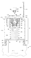
図1及び図6に示すように、開口部14は容器本体12の上面に位置する。開口部14は、容器本体12の口部20の雄ネジ28に螺合する雌ネジ30が形成されている分離部32を有する。分離部32は、円筒形状を有し、下側に開口している凹部を有する。凹部の内周面には、雌ネジ30が、雌ネジ30の中心軸が側部16の円柱形状の中心軸Cと一致するように、形成されている。分離部32の上面には円柱形状の凸部32aが形成されており、後述する圧縮コイルバネ54の下端が配置されている。なお、圧縮コイルバネ54は、例示であって、付勢機構であれば、これに限定されない。
分離部32には、凹部の底部33と分離部32の上面の凸部32aとを貫通する円筒形状の貫通孔34が形成されている。貫通孔34の中心軸は、側部16の円柱形状の中心軸Cと一致している。したがって、分離部32は、分離部32を中心軸Cの周りを回るように、容器本体12に対して回転させると、雄ネジ28と雌ネジ30との螺合が解けるので、分離部32、ひいては開口部14は、容器本体12から分離する構造を有する。
分離部32の底部33には、例えば、ボールスプライン軸48と螺合する軸受50がボルトのような公知の取付機構によって、組み付けられている。軸受50は、例えば、ボールスプライン軸48に軸線が中心軸Cと一致するように、分離部32の底部33に取り付けられている。なお、ボールスプライン軸48と軸受50とは、回転運動を直線運動に変換する機構の一例としてあげたものであって、例えば、台形ネジや、一般の雄ネジ、雌ネジであってもよい。また、材質は、金属として説明しているが、回転運動を直線運動に変換する機能を発揮できれば、限定されず、例えば、樹脂であってもよい。
ボールスプライン軸48は、ボールスプライン軸48がボールスプライン軸48の軸線の周りを回転すると、軸受50に対して、ボールスプライン軸48の軸線が延びる方向に回転しながら移動する。換言すると、ボールスプライン軸48と軸受50とは、ボールスプライン軸48がボールスプライン軸48の軸線が延びる方向に移動するためには、ボールスプライン軸48の軸線の周りを回転しなければならない構造を有している。したがって、ボールスプライン軸48と軸受50とは、ボールスプライン軸48が中心軸Cの延びる方向に移動に伴って、ボールスプライン軸48を回転運動させる運動変換機構として作用する。ここで、中心軸Cは、廃棄針用回収容器10の重心を通るので、ボールスプライン軸48の軸線は、廃棄針用回収容器10の重心を通ることになる。
ボールスプライン軸48は、ボールスプライン軸48が延びる方向において、ボールスプライン軸48の中心を通る貫通孔52を有する。
ボールスプライン軸48の上端部分には、凹部56が形成されている。凹部56の内周側面は、円筒形状を有する。
開口部14は、保持体94の円筒側面を保持するインナー把持部60とインナー把持部60が差し込まれるアウター把持部62とを有する。インナー把持部60とアウター把持部62とは、協働して保持体94を把持する把持機構64として作用する。
アウター把持部62の下側端部は、ボールスプライン軸48の凹部56に相対的回転不能に嵌合されている。アウター把持部62は、円柱形状を有し、上側が開口する凹部66と、凹部66の底部に形成された貫通孔68とを備える。凹部66の開口近傍は、裁頭円錐形状の側面のような外側に広がるテーパーに形成されている。このテーパーは、インナー把持部60の下端部を凹部66に案内する案内機構として作用する。凹部66の内周面の中心と貫通孔68の中心とはいずれも中心軸Cの延長線上に位置している。
アウター把持部62の凹部66には、例えば、付勢機構の一例である圧縮コイルバネ70が圧縮された状態で配置されている。圧縮コイルバネ70は、圧縮コイルバネ54のバネ定数よりも小さいバネ定数を有することが好ましい。圧縮コイルバネ70の上側には、スペーサー72が摺動可能に配置されている。スペーサー72は、円筒形状を有する。スペーサー72は、スペーサー72の対向する側面に、スペーサー72の円筒形状の軸線が延びる方向に長い2つの長孔74が形成されている。
スペーサー72の上側には、インナー把持部60の下側の端部がスペーサー72の上側に接触するように、インナー把持部60が配置されている。
圧縮コイルバネ70の上側の端部には、上側バネ受部材78が配置されている。上側バネ受部材78は、円柱形状を有する。上側バネ受部材78の下側の端部には、凹部76が形成されている。凹部76は、圧縮コイルバネ54の外径よりも若干大きい直径の内周面を有している。上側バネ受部材78の上側にも、凹部80が形成されている。凹部80は、例えば、ベアリング82を保持する。本実施形態では、ベアリングを挙げているが、これに限定されず、摩擦抵抗が少なくなる構成ならかまわず、例えば、オイルレス軸受けや、ブッシュであってもよいし、材質はステンレスや樹脂であってもよい。上側バネ受部材78には、凹部76の底面と凹部80の底面とを貫通する貫通孔84が形成されている。貫通孔84の中心は、中心軸Cの延長線上に位置している。
インナー把持部60の上側の端部には、カバー86が配置されている。カバー86は、円盤部85と円盤部85の下側に形成された筒状部87とを有する。円盤部の中央に貫通孔88が形成されている。筒状部87の内径は、インナー把持部60の外径、アウター把持部62の外径よりも大きく、筒状部87の外径は、圧縮コイルバネ54の内径、貫通孔84の内径、ベアリング82の内径のいずれよりも小さい。
インナー把持部60は、上下方向に貫通する貫通孔61を有する。貫通孔61は、保持体94の外径よりも若干大きい直径を有する。貫通孔61の内側面には、インナー把持部60の外径が小さくなる際の逃げしろとして作用するスリット63が形成されている。貫通孔61の内周面には、保持体94とインナー把持部60とが相対的回転不能に、保持体94に設けられた凹凸に噛合する噛合部(図示せず)が形成されている。
インナー把持部60は、上側の端部は円筒形状を有し、中央の部分がテーパーですぼんでいる形状を有し、下側の端部は円筒形状を有する構造を備えている。上側の端部は、アウター把持部62の外径と略同じ直径を有する。下側の端部は、アウター把持部62の内径とほぼ同じか、若干小さい直径を有する。
カバー86の筒状部87には、貫通孔が形成され、また、アウター把持部62には、雌ネジ穴が形成されている。そして、筒状部87の貫通孔をとおって雌ネジ穴に止めネジ83が螺合している。したがって、ボールスプライン軸48は、アウター把持部62、止めネジ83を介してカバー86と相対的移動不能に組み付けられている。
圧縮コイルバネ54は、圧縮コイルバネ54が若干圧縮された状態で、その下側端部が下側バネ受部材40の凹部42に、その上側端部が上側バネ受部材78の凹部76に配置されているので、上側バネ受部材78を、常に上側に移動しようと、付勢する。この付勢の力は、上側バネ受部材78、ベアリング82を介して、カバー86の円盤部85に伝わる。
止めネジ83の先端は、アウター把持部62の凹部66の内周面よりも内側に出ており、スペーサー72の長孔74に差し込まれている。
スペーサー72は、アウター把持部62の凹部66の内周面において、長孔74の長さだけ、上下方向に摺動することができる。また、圧縮コイルバネ70は、若干圧縮された状態でアウター把持部62の凹部66の内周面の内部に配置されているので、圧縮コイルバネ70は、スペーサー72を付勢している。
このように、開口部14には、保持体94が挿入され、また、後述する注射器本体90から分離された保持体94が通る挿入孔100が、貫通孔52、68、61、スペーサー72の貫通孔によって形成されている。
分離部32の上側には、開口部14を覆うカバー110が設けられている。カバー110は、例えば、円筒側面形状の筒状部112と、筒状部112の上端に形成された開口部116と、開口部116の近傍に形成された外側に広がる鍔部118とを備える。開口部116の直径は、円盤部85の外径より若干大きい。カバー110は、例えば、樹脂で形成されていることが好ましい。カバー110の上部には、ヒンジ支持部119が設けられており、ヒンジ支持部119は、円盤形状の蓋部114の外周から延在したヒンジ部に枢軸122を介して回転可能に支持されている。蓋部114は、開口部116側に設けられた鍔部120を備える。鍔部120は、蓋部114の外周近傍から円筒側面状に延在し、その端部において内側にリングを形成するように延在している。図1及び図6に示すように、蓋部114の鍔部120は、通常、開口部116の鍔部118とカバー110の上部との隙間に入り込んだ状態とされ、これにより、開口部116を密封している。
図1に示すように、以上の廃棄針用回収容器10は、通常、圧縮コイルバネ54、70によって、上方向の付勢力が、それぞれ、上側バネ受部材78、スペーサー72に作用しているので、ボールスプライン軸48、インナー把持部60は、いずれも、最も上側に位置している。また、蓋部114は、開口部116を覆っている。
廃棄針用回収容器10は、以下のようにして用いる。
使用者は、注射器本体90を用いてインシュリン等の薬を身体に投与する。そして、使用済みとなった注射器本体90を、廃棄針用回収容器10を用いて、注射針部96を注射器本体90から確実にかつ簡単に取り外す。
以下、詳細に説明する。まず、図9に示すように、使用者は、蓋部114を、枢軸122の回りを回転させるように、持ち上げて、開口部116を開ける。これにより、使用者は、インナー把持部60の貫通孔61を視認することができ、また、注射器本体90の保持体94をインナー把持部60の貫通孔61に差し込むことができる。
次に、使用者は、注射器本体90の針が下に向くように、片手で、使用済みとなった注射器本体90を持ち、それを廃棄針用回収容器10の上方に位置させる。このとき、注射器本体90の中心軸とインナー把持部60の中心軸、すなわち、中心軸Cとを合わせる。
次に、使用者は、注射器本体90を下方向に移動させ、保持体94の外周面がインナー把持部60の貫通孔61の内周面に接触させる。貫通孔61は、保持体94の外径よりも若干大きい直径を有するので、スムーズに保持体94を貫通孔61に挿入することができる。
さらに、使用者は、注射器本体90を下方向に移動させると、注射器本体90の下端部がインナー把持部60の上端部に接触する。
さらに、注射器本体90を下方向に移動させると、注射器本体90とインナー把持部60とが一緒に下方向に移動する。このとき、圧縮コイルバネ70は圧縮コイルバネ54のバネ定数よりも小さいバネ定数を有するので、圧縮コイルバネ70が圧縮コイルバネ54より先に注射器本体90を下方向に移動させる力に屈する。
そして、インナー把持部60の下側端部は、スペーサー72を下方向に押しながら、かつ、アウター把持部62の上端部のテーパーに接触しながらアウター把持部62の貫通孔に挿入される。スペーサー72は、止めネジ83の先端が長孔74に挿入されているので、長孔74の長手方向、すなわち、下方向に移動する。
インナー把持部60がアウター把持部62の貫通孔に挿入されると、スリット63の隙間を狭めながら貫通孔61の内径を若干小さくするから、インナー把持部60は、保持体94を、貫通孔61と保持体94とが相対的回転不能になるように、確実に把持する。
また、インナー把持部60が保持体94を確実に把持すると同時に、インナー把持部60の下側端部がアウター把持部62の貫通孔に挿入すると、インナー把持部60の下側端部のテーパーと、アウター把持部62の上側端部のテーパーとによって、インナー把持部60とアウター把持部62とは、嵌合状態になるので、インナー把持部60とアウター把持部62とは、相対的回転不能状態になる(この状態を、把持回転開始状態という)。
さらに、注射器本体90を下方向に移動させると、圧縮コイルバネ54の付勢が屈し、ボールスプライン軸48が下方向に移動する。ボールスプライン軸48が下方向に移動すると、ボールスプライン軸48と軸受50との螺合により、ボールスプライン軸48が回転しながら下方向に移動する。ボールスプライン軸48の回転は、アウター把持部62、インナー把持部60を介して、一方は、保持体94に、他方は、さらに止めネジ83を介してカバー86に伝わる。
このとき、注射器本体90は、使用者がしっかり注射器本体90を保持しているので、注射器本体90と保持体94との間に回転力が作用し、実際に回転する。つまり、使用者が注射器本体90を下げると、注射器本体90の先端92と保持体94との螺合を解く回転力が作用する。また、注射器本体90の先端92と保持体94との螺合を解く回転力は、容器本体12にも作用するが、滑止部22によって、ほとんど回転しない。
また、ボールスプライン軸48の上下動は、容器本体12の中心軸Cの延長線上、換言すると、廃棄針用回収容器10の重心を通る軌道で行われる。つまり、中心軸Cは、挿入孔100が延びる孔方向と一致し、また、保持体94は、孔方向への線運動をすることになる。
圧縮コイルバネ54は、上側バネ受部材78と下側バネ受部材40とによって両端を保持されているので、上側バネ受部材78は、下方向に略平行移動する。そこで、仮に、滑止部22の滑り止め力よりも大きい回転力が容器本体12に作用して、容器本体12が回転しそうになったら、使用者は、注射器本体90を保持している手と反対の手で上側バネ受部材78や容器本体12を保持すればよい。
なお、使用者は、使用者の手等がカバー86に接触しない状態で、注射器本体90をしっかり持って、下方向に押す作業をするだけでいいので、ボールスプライン軸48の移動にともなって、カバー86が回転しても、押し下げるという作業に支障はほとんどない。
そして、さらに、注射器本体90を下方向に移動させると、やがて、図10に示すように、上側バネ受部材78の下側が、下側バネ受部材40の上面に接触して、注射器本体90の下方向への移動ができなくなる(この状態を把持回転終了状態という)。
このようにして、把持回転開始状態から把持回転終了状態にすることにより、保持体94を注射器本体90の先端92から分離させる。注射器本体90の先端92から分離した保持体94は、重力によって、挿入孔100、すなわち、スペーサー72の貫通孔、インナー把持部60の貫通孔68、ボールスプライン軸48の貫通孔52を、自由落下状態で、通って、容器本体12に収容され、回収される。
もし、一回の把持回転開始状態から把持回転終了状態への操作で、保持体94が若干回転しつつも、保持体94が注射器本体90の先端92から完全に分離しなかった場合、把持回転終了状態で、使用者は、注射器本体90を保持している手の小指球でカバー86を下側に押さえながら注射器本体90を上側に引き抜く。このとき、カバー86が下側に押さえられているから、止めネジ83を介してアウター把持部62は、下方向に押しつけられている。
このような状態で、注射器本体90を上側に引き抜くと、インナー把持部60がアウター把持部62とインナー把持部60との嵌合による引っ張り強さに屈して、やがて、インナー把持部60がアウター把持部62から抜け、ひいては、インナー把持部60の貫通孔61の内径が元の大きさに戻り、貫通孔61が作用していた保持体94の保持力がほとんどなくなり、インナー把持部60の貫通孔61から保持体94が抜ける。
次に、使用者の手を上方に移動させると、圧縮コイルバネ54の付勢力により、ボールスプライン軸48が上方向に移動し、図9に示すような元の状態になる。
そして、使用者は、蓋部114を回転させて、開口部116を覆う。これにより、容器本体12に収容され、回収された保持体94は、蓋部114の密閉により、容器本体12にほぼ隔離された状態になるので、保持体94の針に付着した血液等から接触による使用者等への感染をより確実に防止することができる。
使用者は、把持回転開始状態から把持回転終了状態を含む上述の作業を反復することにより、確実に、かつ、簡単に、保持体94を注射器本体90の先端92から完全に分離させることができる。特に、使用者が、把持回転開始状態から把持回転終了状態を含む以上の作業を反復する手の動きに着目すれば、使用者は、単に、手に注射器本体90を保持した状態で、中心軸Cの延長線上を上下させているだけであるので、廃棄針用回収容器10は、従来のような複雑な機構や電源を必要としない。
ところで、廃棄針用回収容器10の容器本体12は一般の容器を用いることができる。その場合、その一般の容器に取り付ける廃棄針用回収部品を用いればよい。
そのような廃棄針用回収部品は、例えば、図1、図9において、その一般の容器本体の雌ネジに螺合によって接続される雌ネジ30のような接続機構と、保持体94が挿入される挿入孔100が形成された開口部14と、を備えればよい。そして、開口部14は、保持体94を把持する把持機構64と、この把持機構64の挿入孔100が延びる孔方向への線運動に伴って、把持機構64を回転運動させる運動変換機構とを有すればよいことは、当業者であれば自明なことである。
図11及び図12を参照して、別の実施形態について説明する。
図11及び図12に示す廃棄針用回収容器10aは、容器本体12aと開口部14aとを備えている。容器本体12aは、スペーサー36と、下側バネ受部材40とが設けられていること以外は、図1から図6に示す廃棄針用回収容器10の容器本体12と同じであり、また、開口部14aは、廃棄口部24の向きがことなること以外は、図1から図6に示す廃棄針用回収容器10の開口部14と同じであるので、同一符号を付して説明を省略する。
廃棄口部24は、側部16の中心軸Cと略直角の方向に延びる中心軸を有する円筒形状に形成されているが、これに限定されず、任意の方向に延びる中心軸を有する円筒形状に形成されていてもよい。廃棄口部24の外周は、雄ネジが形成されている。開閉部材26は、例えば、円盤形状の基部と、この基部の一方の底面に形成された凹部と、基部の外周側面に形成された把持部とを有する。凹部の内周面には、例えば、廃棄口部24の外周の雄ネジと螺合可能な雌ネジが形成されている。したがって、開閉部材26は、必要なときに、開閉部材26を回転させることにより、廃棄口部24を開閉させることができる。
開口部14aは、例えば、分離部32の上側に円柱形状のスペーサー36を有する。スペーサー36は、分離部32の円筒外周面の直径と略同じ直径を有する。スペーサー36には、その円中軸が延びる方向に貫通孔38が形成されている。貫通孔38は、貫通孔38の中心軸が側部16の円柱形状の中心軸Cと一致するように、スペーサー36に形成されている。
開口部14aは、スペーサー36の上側に下側バネ受部材40を有する。下側バネ受部材40は、略円柱形状を有し、その上側中央に凹部42が形成されている。凹部42の底部44の中央には、下側バネ受部材40の下側の面を貫通する貫通孔46が、貫通孔46の中心軸が側部16の円柱形状の中心軸Cと一致するように、形成されている。したがって、貫通孔34、貫通孔38、貫通孔46は、いずれも、側部16の円柱形状の中心軸Cと一致しているので、同心円を形成している。また、貫通孔34、貫通孔38、貫通孔46は、いずれも、ボールスプライン軸48を非接触かつ回転可能に挿通できる直径を有する。
下側バネ受部材40の凹部42には、圧縮コイルバネ54の下端が配置されている。圧縮コイルバネ54は、ボールスプライン軸48が圧縮コイルバネ54の内側に位置し、回転可能に上下することができるように、ボールスプライン軸48の外径よりも大きい内径とすることが好ましい。
開口部14aは、分離部32の上側に円柱形状のスペーサー36やスペーサー36の上側に下側バネ受部材40を有するので、図1から図6に示す廃棄針用回収容器10よりも、ボールスプライン軸48のストロークを短くすることができる。
以上のように、使用者は、図11及び図12に示す廃棄針用回収容器10aを把持回転開始状態から把持回転終了状態までの作業を含む上述の作業を反復することにより、確実に、かつ、簡単に、筒状部99bを注射器本体98の先端98aから完全に分離させることができる。特に、使用者が、把持回転開始状態から把持回転終了状態を含む上述の作業を反復する手の動きに着目すれば、使用者は、単に、手に注射器本体98を保持した状態で、中心軸Cの延長線上を上下させているだけであるので、図11及び図12に示す廃棄針用回収容器10aも、従来のような複雑な機構や電源を必要としない。
図13から図18を参照して、さらに別の実施形態について説明する。
図13に示すように、廃棄針用回収容器10bは、上述の廃棄針用回収容器10及び10aと同様、図7に示す注射器本体90の先端92に、保持体94を介して螺合された注射針部96を回収するために用いられる。廃棄針用回収容器10bは、容器本体12bと開口部14bとを備えている。開口部14bには、容器本体12bの上面に位置し、保持体94が挿入される挿入孔100が形成されている。
容器本体12bは、上述の容器本体12及び12aと同様の構造を有する。図13において、側部16に形成されている廃棄口部24及び開閉部材26の記載、並びに底部18に形成されている滑止部22の記載は、省略している。
容器本体12bは、円柱側面状の側部16と、側部16の下部を覆う底部18と、側部16の上部を覆う上部16aを有する縦断面が略U字状の容器である。上部16aは、円盤に形成され中央に開口している口部20を有する。側部16は、円柱側面状としたが、他の形状、例えば、四角柱側面状、八角形側面状、楕円柱側面形状等であってもよいし、裁頭円錐形状、裁頭角錐形状であってもよい。口部20は、円形状の穴であり、その中心は、側部16の円柱形状の中心軸Cと一致している。中心軸Cは後述するように、把持機構の挿入孔100が延びる孔方向と一致している。
口部20は、側部16の円柱形状の中心軸Cと一致するように、上部16aに円筒形状に形成されている。口部20の円筒形状の内周面は、後述するように、開口部14bに形成された溝141と嵌合するように、溝141の形状と略同一の形状を有する。口部20の円筒形状の内周面の中心は、側部16の円柱形状の中心軸Cの近傍に位置している。
開口部14bは容器本体12bの上面に位置する。開口部14bは、容器本体12bの口部20の開口に嵌合する溝141が形成されているナット部140と、ナット部140に螺合しているボルト部150と、を有する。
ナット部140は、略円筒形状を有し、上側に開口している凹部144を有する。凹部144の中央には、凸部142が形成されている。凸部142の中央には中心軸Cが延びる方向に貫通する貫通穴が形成され、その貫通穴の内周面に雌ネジ部146が形成されている。
ナット部140の上面には円盤形状の縁部が形成されており、この縁部に、口部20の開口が係合可能な溝141が形成されている。
ナット部140の下部には、複数の雌ネジが形成されている。複数の雌ネジは、それぞれ、複数のシャフト176の先端の雄ネジ部に螺合している。複数のシャフト176は、これらの軸心が中心軸Cの延びる方向と並行になるように、かつ、ナット部140が下方に移動しないように、ナット部140を支持している。
複数のシャフト176の下端には、互いのシャフト176の平行度を維持するように、底部18の近傍に配置されたシャフトベース175がボルトを介して取り付けられている。
ナット部140の凹部144には、圧縮コイルバネ154の下端が配置されている。なお、圧縮コイルバネ154は、例示であって、付勢機構であれば、これに限定されない。
ナット部140の雌ネジ部146には、ボルト部150の雄ネジ部155が螺合している。ボルト部150は、雄ネジ部155の中心線と略同一の中心線を有する貫通穴151が形成されている。貫通穴151は、ボルト部150の雄ネジ部155の延びる方向に貫通している。したがって、ボルト部150が中心軸Cの延びる移動方向に移動させようとすると、ボルト部150は、中心軸Cの周りを回りながら中心軸Cの延びる移動方向に移動する。したがって、ボルト部150とナット部140とは、運動変換機構として作用する。
貫通穴151の上端側には、貫通穴151の内径よりも大きい内径を有する円柱側面形状の凹部156が形成されている。さらに、凹部156の上端側には、凹部156よりも内径が大きい同心円柱側面形状の凹部152が形成されている。
凹部156には、把持機構190を上方向に付勢可能に圧縮コイルバネ70が配置されている。圧縮コイルバネ70の上端は、凹部152の底部と略同じ位置にある。
凹部152には、把持機構190とその上端に保持体94が挿入される挿入ガイド200とが配置されている。把持機構190と挿入ガイド200との間には、中央に穴が設けられている可撓性のシート180が配置されている。
可撓性のシート180の穴の寸法は、保持体94の外形よりも若干小さいことが好ましい。より具体的には、把持機構64の内周面とシート180の穴の周囲との間の寸法は、円柱形状の保持体94の高さ(厚さ)寸法と略同じであることが好ましい。
把持機構190は、これの上端及び下端に貫通している貫通穴194が形成されている略円筒形状を有する。把持機構190には、把持機構190の円筒側面と貫通穴194をと貫通するスリット192が形成されている。スリット192は、後述する保持体94を回転させるローラー部135が回転可能に収容できる大きさを有している。
図14に示すように、ローラー部135は、挿入孔100に挿通された保持体94の側面に接触できるような位置に、スリット192内に位置されている。図13に示すように、ローラー部135は、把持機構190が下方に移動したとき、ローラー部135がすぐに下方に移動するように、上下方向において、スリット192の上方に位置することが好ましい。
挿入ガイド200は、そのほとんどをボルト部150の凹部152に収容されるような縦断面が凸形状を有する。挿入ガイド200は、円盤形状の鍔部201と、鍔部201と同心円状に形成された円筒形状の本体部202とを備える。挿入ガイド200は、保持体94が挿入される貫通穴203が形成されている。
貫通穴203の上端側には、保持体94が容易に貫通穴203に導けるように、テーパー部204が形成されている。保持体94が簡単に把持機構190の貫通穴194に導けるように、貫通穴203の中心が中心軸Cと略同一に位置し、かつ、貫通穴203の内径は保持体94の外径よりも大きく設定されている。
挿入ガイド200の周囲には、回転プレート216が配置されている。回転プレート216は、ベアリング82を介してボルト部150の上端部に回転可能に取り付けられている。
圧縮コイルバネ154は、上端が回転プレートを回転可能に保持しているベアリング82に接触するように、下端がナット部140の凹部144に接触するように、配置される。これにより、圧縮コイルバネ154は、ボルト部150を上方向に付勢する。
開口部14bは、ボルト部150が回転する回転軸を中心とし、かつ、その回転軸の周りの回転をしない内歯車172を備えている。
図15に示すように、内歯車172は、中央に穴がある円盤形状を有し、穴が形成されている側に遊星歯車173に噛合する歯が形成されている。内歯車172は、複数のシャフト176と同じ数の貫通穴が形成されている。内歯車172に形成されている複数の貫通穴には、それぞれ、複数のシャフト176が挿通されている。したがって、内歯車172は、ボルト部150の移動に伴って、中心軸Cが延びる方向に沿って平行移動可能なように、かつ、中心軸Cの周りを回転しないように複数のシャフト176に取り付けられている。
図13に示すように、開口部14bは、内歯車172に噛合する遊星歯車(第1の遊星歯車)173と、遊星歯車173と選択的に噛合する遊星歯車(第2の遊星歯車)174と、を有する。
遊星歯車173は、ボルト部150の回転に従って中心軸Cの周りを公転しかつ自転するように、ローラーピン162によって支持されている。ローラーピン162は、ボルト部150の下端にボルト170で取り付けられたロッドガイド166に取り付けられている。ローラーピン162は、留めネジ164によって、ロッドガイド166からは容易に抜けることを防止している。
開口部14bは、ロッドガイド166に回転可能に、かつ、軸方向にスライド可能に保持された噛合切替機構130を備える。
噛合切替機構130は、ローラー部135と、一端がローラー部135の回転軸に相対的移動不能に形成されたローラーロッド131とを有する。ローラーロッド131は、ロッドガイド166を貫通している。ローラーロッド131には、ロッドガイド166の上側に圧縮コイルバネ133を付勢した状態になるように、ロッドピン132が取り付けられている。圧縮コイルバネ133は、貫通穴151の側面に形成された凹部157に配置されている。
ローラーロッド131の他端には、相対的移動不能に形成された遊星歯車174が形成されている。ローラーロッド131には、遊星歯車174とロッドガイド166との間にもロッドピン134が取り付けられている。遊星歯車174は、上方向側が若干小さい外径を有する形状である好ましい。ローラーロッド131は、ロッドガイド166に回転可能に、かつ、摺動可能にロッドガイド166に保持されているから、通常は、圧縮コイルバネ133によってローラーロッド131が上方向に付勢され、遊星歯車174は遊星歯車173に噛合している(噛合状態)。
しかし、把持機構190が下方に移動した場合、ローラーロッド131が、圧縮コイルバネ133の付勢力に屈して、下方に押し下げられるので、遊星歯車174がロッドガイド166に対して下方に移動される。これにより、遊星歯車174と遊星歯車173との間の噛合は解除される(噛合解除状態)。よって、ローラー部135とローラーロッド131と圧縮コイルバネ133とによって噛合切替機構130が形成されている。
また、内歯車172と遊星歯車173と遊星歯車174とローラー部135とローラーロッド131と圧縮コイルバネ133とは、運動変換機構(別の運動変換機構)を構成している。
以上の廃棄針用回収容器10bは、以下のようにして用いる。
使用者は、注射器本体90を用いてインシュリン等の薬を身体に投与する。そして、使用済みとなった注射器本体90を、廃棄針用回収容器10bを用いて、注射針部96を注射器本体90から確実にかつ簡単に取り外す。
以下、詳細に説明する。まず、廃棄針用回収容器10bが図15に示すような状態で、図16に示すように、使用者は、注射器本体90の針が下に向くように、片手で、使用済みとなった注射器本体90を持ち、それを廃棄針用回収容器10bの上方に位置させる。このとき、注射器本体90の中心軸と把持機構190の中心軸、すなわち、中心軸Cとを合わせる。
次に、使用者は、注射器本体90を下方向に移動させ、注射器本体90の保持体94をシート180の中央に形成されている穴に挿通させる。シート180の中央に形成されている穴は注射器本体90の保持体94の外径よりも小さいが、シート180には可撓性があるので、穴の直径は、保持体94の外径と略同じ寸法の穴になり、保持体94は、容易に、シート180の穴を挿通し、ボルト部150の貫通穴194に挿入される。
図16に示すように、さらに、使用者は、把持機構190を付勢している圧縮コイルバネ70の付勢力を屈するべく、注射器本体90を下方向に移動させる。これにより、把持機構190は、ローラー部135(ローラーロッド131)を押し下げるので、遊星歯車174は、ロッドガイド166に対して下方に移動する。そして、遊星歯車173と遊星歯車174との噛合は、解除される。すなわち、遊星歯車173と遊星歯車174とは、噛合状態から噛合解除状態になる。
さらに、使用者は、把持機構190を付勢している圧縮コイルバネ70の付勢力を屈するべく、注射器本体90を下方向に移動させる。これにより、保持体94を挿通している把持機構190をボルト部150の凹部156に挿通させる。凹部156の内径は、把持機構190の外径よりも若干小さく設定されているから、把持機構190は、保持体94を確実に把持する。すなわち、把持機構190は、保持体把持状態になる。
さらに、使用者は、ボルト部150を付勢している圧縮コイルバネ154の付勢力を屈するべく、注射器本体90を下方向に移動させると、ボルト部150は、これが一方の移動方向への線運動をするので、ボルト部150の雄ネジ部155とナット部140の雌ネジ部146とが螺合しながら、中心軸Cの周りを回転する。すなわち、ボルト部150は一方の回転方向に回転運動をする。ボルト部150の凹部156と把持機構190とは嵌合されているので、ボルト部150の回転は、把持機構190を介して保持体94を回転させる。
ボルト部150が中心軸Cの周りを回転すると、ロッドガイド166も中心軸Cの周りを回転するので、内歯車172に噛合している遊星歯車173は中心軸Cの周りの公転及び自転をする。しかし、遊星歯車173と遊星歯車174とは噛合していないので、遊星歯車174ひいてはローラー部135は、中心軸Cの周りを公転するだけで、自転はしない。つまり、ローラー部135は把持機構190に対して相対的な移動はほとんどないから、ローラー部135は、保持体94を回転させる作用はほとんど生じない。
そして、図17に示すように、挿入ガイド200の下端部がナット部140の凹部144に接触すると、使用者は、注射器本体90を下方向に移動させることをやめる。
そして、図18に示すように、使用者は、注射器本体90を上方向に移動させる。このとき、注射器本体90ひいては保持体94に作用している下方向への付勢力は小さくなる。これにより、まず、圧縮コイルバネ70の付勢力によって、把持機構190がボルト部150に対して上方向に移動する。
次に、把持機構190の上方向への移動に伴って、ローラー部135ひいては遊星歯車174がボルト部150に対して上方向に移動し、やがて、遊星歯車174と遊星歯車173とが噛合する。このとき、遊星歯車174は上方向側が若干小さい外径を有する形状であるから、遊星歯車174と遊星歯車173との噛合はスムーズに行われる。
これと同時期に、把持機構190はボルト部150の凹部156から外れ、把持機構190は保持体94の把持をほとんどしなくなる。すなわち、把持機構190は、保持体把持状態から保持体把持解除状態になる。
さらに、使用者が注射器本体90を上方向に移動させると、圧縮コイルバネ154の付勢力により、ボルト部150がナット部140に対して上方に移動する。このとき、ボルト部150の雄ネジ部155がナット部140の雌ネジ部146に螺合しているので、ボルト部150は、注射器本体90を下方向に移動させている時と反対の方向に回転する(他方の回転方向)。
この回転方向は、保持体94を注射器本体90に締め付ける回転方向であって保持体94を注射器本体90から外すための回転方向ではない。しかし、把持機構190は、保持体94をほとんど保持していないので、をボルト部150の中心軸Cの周りの回転による保持体94の締め付けはほとんど生じない。
一方、ボルト部150は、中心軸Cの周りを回転するので、ロッドガイド166ひいては遊星歯車173が中心軸Cの周りを公転する。さらに、遊星歯車173は内歯車172に噛合しているので、遊星歯車173は自転もする。したがって、遊星歯車174及びローラーロッド131を介してローラー部135は自転もする。このときのローラー部135の回転方向は、遊星歯車173を介しているので、把持機構190に対して保持体94を緩める方向になる。
使用者は、以上の手順を複数回繰り返すことにより、簡単に注射器本体90から保持体94を取り外すことができる。しかも、廃棄針用回収容器10bは、注射器本体90を上方向に移動させているときも、ローラー部135が保持体94を注射器本体90から外すように作用するので、廃棄針用回収容器10、10aよりも少ない上下運動で、確実に保持体94を注射器本体90から外すことができる。
本発明は、上述の実施形態に限定されない。例えば、上述の廃棄針用回収容器は、注射針と共に、医療廃棄物として処理できる材質(例えば、注射針がステンレスで形成されている場合、廃棄針用回収容器に用いられている金属は、ステンレスで形成されていることが好ましい。)であることが好ましい。
また、廃棄針用回収容器10bでは、回転力の伝達を、内歯車172、遊星歯車173、174の噛合による歯車伝達としたが、互いに滑りにくい円盤形状による摩擦伝達であってもよい。
また、実施形態で示した具体的な構成は、すべて例示であって、同一作用効果を奏する別の構成に置き換えてもよいことは言うまでもない。
C 中心軸
F 設置面
10 廃棄針用回収容器
12 容器本体
14 開口部
16 側部
18 底部
20 口部
22 滑止部
24 廃棄口
26 開閉部材
28 雄ネジ
30 雌ネジ
32 分離部
33 底部
34 貫通孔
36 スペーサー
38 貫通孔
40 下側バネ受部材
42 凹部
44 底部
46 貫通孔
48 ボールスプライン軸
50 軸受
52 貫通孔
54 圧縮コイルバネ
56 凹部
60 インナー把持部
61 貫通孔
62 アウター把持部
63 スリット
64 把持機構
66 凹部
68 貫通孔
70 圧縮コイルバネ
72 スペーサー
74 長孔
76 凹部
78 上側バネ受部材
80 凹部
82 ベアリング
83 止めネジ
84 貫通孔
85 円盤部
86 カバー
87 筒状部
88 貫通孔
90 注射器本体
92 先端
94 保持体
96 注射針部
100 挿入孔
F 設置面
10 廃棄針用回収容器
12 容器本体
14 開口部
16 側部
18 底部
20 口部
22 滑止部
24 廃棄口
26 開閉部材
28 雄ネジ
30 雌ネジ
32 分離部
33 底部
34 貫通孔
36 スペーサー
38 貫通孔
40 下側バネ受部材
42 凹部
44 底部
46 貫通孔
48 ボールスプライン軸
50 軸受
52 貫通孔
54 圧縮コイルバネ
56 凹部
60 インナー把持部
61 貫通孔
62 アウター把持部
63 スリット
64 把持機構
66 凹部
68 貫通孔
70 圧縮コイルバネ
72 スペーサー
74 長孔
76 凹部
78 上側バネ受部材
80 凹部
82 ベアリング
83 止めネジ
84 貫通孔
85 円盤部
86 カバー
87 筒状部
88 貫通孔
90 注射器本体
92 先端
94 保持体
96 注射針部
100 挿入孔
Claims (15)
- 注射器本体の先端に保持体を介して螺合された注射針部を回収する廃棄針用回収容器であって、
容器本体と、この容器本体の上面に位置し、前記保持体が挿入される挿入孔が形成された開口部と、を備え、
前記開口部は、
前記保持体を把持する把持機構と、
前記把持機構の前記挿入孔が延びる孔方向への線運動に伴って、前記把持機構を回転運動させる運動変換機構と、を有し、
前記挿入孔に挿入された保持体が、前記孔方向に動かされることで前記注射器本体から分離される廃棄針用回収容器。 - 前記把持機構は、前記線運動が、前記廃棄針用回収容器の重心を通る軌道で行われる位置に設けられている請求項1記載の廃棄針用回収容器。
- 前記把持機構は、前記保持体に設けられた凹凸に噛合して、前記把持機構に対する前記保持体の相対的な回転を禁止する噛合部を有する請求項1に記載の廃棄針用回収容器。
- さらに、前記把持機構を上方向に付勢する付勢機構を備える請求項1に記載の廃棄針用回収容器。
- 前記開口部を有する分離部は、前記容器本体に対して着脱可能に設けられている請求項1に記載の廃棄針用回収容器。
- 前記容器本体は、分離された注射針部を廃棄するための廃棄口と、この廃棄口を開閉する開閉部材と、を有する請求項1に記載の廃棄針用回収容器。
- 前記容器本体は、注射器本体の先端に保持体を介して嵌合された注射針部を回収する回収機構をさらに備える請求項1に記載の廃棄針用回収容器。
- 注射器本体の先端に保持体を介して螺合された注射針部を回収する廃棄針用回収容器に用いられる廃棄針用回収部品であって、
前記廃棄針用回収容器の容器本体に接続される接続機構と、前記保持体が挿入される挿入孔が形成された開口部と、を備え、
前記開口部は、
前記保持体を把持する把持機構と、
前記把持機構の前記挿入孔が延びる孔方向への線運動に伴って、前記把持機構を回転運動させる運動変換機構と、を有する廃棄針用回収部品。 - 前記運動変換機構は、前記孔方向のうち、一方の移動方向への線運動に伴って、前記把持機構を前記保持体を把持する保持体把持状態にさせながら前記把持機構を一方の回転方向に回転運動させ、
前記開口部は、前記孔方向のうち、他方の移動方向への線運動に伴って、前記把持機構を前記保持体を把持しない保持体把持解除状態にさせながら前記保持体を前記一方の回転方向に回転運動させる別の運動変換機構をさらに有し、
前記挿入孔に挿入された保持体が、前記孔方向の一方及び他方の移動方向に動かされることで前記注射器本体から分離される請求項1に記載の廃棄針用回収容器。 - 前記運動変換機構は、さらに、前記孔方向のうち、前記一方の移動方向への線運動に伴って、前記把持機構と共に、前記一方の回転方向に回転運動し、また、前記他方の移動方向への線運動に伴って、前記把持機構と共に、前記他方の回転方向に回転運動し、
前記別の運動変換機構は、前記孔方向のうち、前記他方の移動方向への線運動に伴って、前記運動変換機構の前記他方の回転方向の回転に基づいて前記保持体を回転させる、請求項9に記載の廃棄針用回収容器。 - 前記別の運動変換機構は、
前記運動変換機構が回転する回転軸を中心とし、かつ、前記回転軸の周りの回転をしない内歯車と
前記内歯車に噛合する第1の遊星歯車であって前記運動変換機構の回転に従って前記回転軸の周りを公転しかつ自転する第1の遊星歯車と、
前記第1の遊星歯車と選択的に噛合する第2の遊星歯車であって前記運動変換機構の回転に従って前記回転軸の周りを公転しかつ自転する第2の遊星歯車と、
前記第1の遊星歯車と前記第2の遊星歯車とが噛合した噛合状態と、これらが噛合しない噛合解除状態とを切り替える噛合切替機構と、
前記第2の遊星歯車の出力軸に相対的回転不能に結合したローラー部であって、前記ローラー部の側面が前記挿入孔に挿入された保持体の側面に接触するローラー部と、を有し、
前記噛合切替機構は、前記運動変換機構が前記孔方向のうち、一方の移動方向への線運動をしているときは、前記噛合解除状態となり、前記運動変換機構が前記孔方向のうち、他方の移動方向への線運動をしているときは、前記噛合状態となる、請求項10に記載の廃棄針用回収容器。 - 前記噛合切替機構は、
前記ローラー部と前記第2の遊星歯車とを相対的回転不能に連結するシャフトであって前記孔方向に移動可能に前記運動変換機構に保持されているシャフトと、
前記シャフトを、前記孔方向のうち、前記他方の移動方向に付勢する第1の付勢機構と、
前記運動変換機構が前記孔方向のうち、前記一方の移動方向への線運動するとき、前記シャフトを前記一方の移動方向へ移動させ前記第1の遊星歯車と前記第2の遊星歯車とを前記噛合解除状態にする第2の付勢機構とを有する請求項11に記載の廃棄針用回収容器。 - 前記別の運動変換機構は、前記内歯車を、前記回転軸の周りの回転をしないように、かつ、前記孔方向に平行移動できるように案内する案内機構を有する請求項12に記載の廃棄針用回収容器。
- 前記開口部は、前記挿入孔の近傍に設けられた、中央に穴が設けられている可撓性のシートをさらに有する請求項9に記載の廃棄針用回収容器。
- 前記運動変換機構は、前記孔方向のうち、一方の移動方向への線運動に伴って、前記把持機構を前記保持体を把持する保持体把持状態にさせながら前記把持機構を一方の回転方向に回転運動させ、
前記開口部は、前記孔方向のうち、他方の移動方向への線運動に伴って、前記把持機構を前記保持体を把持しない保持体把持解除状態にさせながら前記保持体を前記一方の回転方向に回転運動させる別の運動変換機構をさらに有し、
前記挿入孔に挿入された保持体が、前記孔方向の一方及び他方の移動方向に動かされることで前記注射器本体から分離される請求項8に記載の廃棄針用回収部品。
Applications Claiming Priority (2)
| Application Number | Priority Date | Filing Date | Title |
|---|---|---|---|
| JP2009084506A JP2012110356A (ja) | 2009-03-31 | 2009-03-31 | 廃棄針用回収容器及び廃棄針用回収部品 |
| JP2009-084506 | 2009-03-31 |
Publications (1)
| Publication Number | Publication Date |
|---|---|
| WO2010113388A1 true WO2010113388A1 (ja) | 2010-10-07 |
Family
ID=42827707
Family Applications (1)
| Application Number | Title | Priority Date | Filing Date |
|---|---|---|---|
| PCT/JP2010/001483 Ceased WO2010113388A1 (ja) | 2009-03-31 | 2010-03-04 | 廃棄針用回収容器及び廃棄針用回収部品 |
Country Status (2)
| Country | Link |
|---|---|
| JP (1) | JP2012110356A (ja) |
| WO (1) | WO2010113388A1 (ja) |
Cited By (9)
| Publication number | Priority date | Publication date | Assignee | Title |
|---|---|---|---|---|
| EP2596825A1 (en) * | 2011-11-24 | 2013-05-29 | Sanofi-Aventis Deutschland GmbH | Needle assembly attachment and removal device |
| EP2636419A1 (en) * | 2012-03-07 | 2013-09-11 | Sanofi-Aventis Deutschland GmbH | Needle assembly removal device and disposal device |
| JP2014516718A (ja) * | 2011-05-30 | 2014-07-17 | サノフィ−アベンティス・ドイチュラント・ゲゼルシャフト・ミット・ベシュレンクテル・ハフツング | ニードルアセンブリの取り外しデバイス |
| US8882706B2 (en) | 2009-12-04 | 2014-11-11 | Becton, Dickinson And Company | Pen needle removal device for a drug delivery device |
| CN105007967A (zh) * | 2012-12-05 | 2015-10-28 | 赛诺菲-安万特德国有限公司 | 针组件更换装置 |
| CN107569353A (zh) * | 2017-10-18 | 2018-01-12 | 柳州市人民医院 | 便携式通用利器盒 |
| CN108434558A (zh) * | 2018-03-26 | 2018-08-24 | 何连交 | 一种利器收集桶 |
| US10456525B2 (en) | 2012-05-07 | 2019-10-29 | Sanofi-Aventis Deutschland Gmbh | Detent mechanism for a medicament delivery device |
| WO2021044285A1 (es) * | 2019-09-06 | 2021-03-11 | Mantilla Otero Monica | Dispositivo de agujas de manejo seguro |
Families Citing this family (1)
| Publication number | Priority date | Publication date | Assignee | Title |
|---|---|---|---|---|
| CN106994051B (zh) * | 2016-01-25 | 2019-11-15 | 北京大学深圳医院 | 便于收集锐器的锐器盒 |
Citations (8)
| Publication number | Priority date | Publication date | Assignee | Title |
|---|---|---|---|---|
| JPS62242163A (ja) * | 1986-04-14 | 1987-10-22 | Matsushita Electric Works Ltd | 遊星変速装置 |
| JPH0533145Y2 (ja) * | 1987-11-24 | 1993-08-24 | ||
| JPH0546449Y2 (ja) * | 1990-03-20 | 1993-12-06 | ||
| JPH07464A (ja) * | 1993-02-16 | 1995-01-06 | Sang In Han | 針除去装置 |
| JP3019500U (ja) * | 1995-06-16 | 1995-12-19 | 良男 別府 | 医療用針の取り外し装置 |
| JP2004074731A (ja) * | 2002-08-22 | 2004-03-11 | Seiko Epson Corp | 記録装置 |
| JP3115180U (ja) * | 2005-07-28 | 2005-11-04 | 有二 村上 | 注射針取り外し器 |
| JP2009225825A (ja) * | 2008-03-19 | 2009-10-08 | Terumo Corp | 注射針取外し装置及び注射針廃棄容器 |
-
2009
- 2009-03-31 JP JP2009084506A patent/JP2012110356A/ja active Pending
-
2010
- 2010-03-04 WO PCT/JP2010/001483 patent/WO2010113388A1/ja not_active Ceased
Patent Citations (8)
| Publication number | Priority date | Publication date | Assignee | Title |
|---|---|---|---|---|
| JPS62242163A (ja) * | 1986-04-14 | 1987-10-22 | Matsushita Electric Works Ltd | 遊星変速装置 |
| JPH0533145Y2 (ja) * | 1987-11-24 | 1993-08-24 | ||
| JPH0546449Y2 (ja) * | 1990-03-20 | 1993-12-06 | ||
| JPH07464A (ja) * | 1993-02-16 | 1995-01-06 | Sang In Han | 針除去装置 |
| JP3019500U (ja) * | 1995-06-16 | 1995-12-19 | 良男 別府 | 医療用針の取り外し装置 |
| JP2004074731A (ja) * | 2002-08-22 | 2004-03-11 | Seiko Epson Corp | 記録装置 |
| JP3115180U (ja) * | 2005-07-28 | 2005-11-04 | 有二 村上 | 注射針取り外し器 |
| JP2009225825A (ja) * | 2008-03-19 | 2009-10-08 | Terumo Corp | 注射針取外し装置及び注射針廃棄容器 |
Cited By (24)
| Publication number | Priority date | Publication date | Assignee | Title |
|---|---|---|---|---|
| US8882706B2 (en) | 2009-12-04 | 2014-11-11 | Becton, Dickinson And Company | Pen needle removal device for a drug delivery device |
| US12569626B2 (en) | 2009-12-04 | 2026-03-10 | Becton, Dickinson And Company | Pen needle removal device for a drug delivery device |
| US11786670B2 (en) | 2009-12-04 | 2023-10-17 | Becton, Dickinson And Company | Pen needle removal device for a drug delivery device |
| US10744273B2 (en) | 2009-12-04 | 2020-08-18 | Becton, Dickinson And Company | Pen needle removal device for a drug delivery device |
| US9861760B2 (en) | 2009-12-04 | 2018-01-09 | Becton, Dickinson And Company | Pen needle removal device for a drug delivery device |
| JP2014516718A (ja) * | 2011-05-30 | 2014-07-17 | サノフィ−アベンティス・ドイチュラント・ゲゼルシャフト・ミット・ベシュレンクテル・ハフツング | ニードルアセンブリの取り外しデバイス |
| CN104053468B (zh) * | 2011-11-24 | 2016-08-24 | 赛诺菲-安万特德国有限公司 | 针组件附接和移除装置 |
| US9694143B2 (en) | 2011-11-24 | 2017-07-04 | Sanofi-Aventis Deutschland Gmbh | Needle assembly attachment and removal device |
| WO2013076244A1 (en) * | 2011-11-24 | 2013-05-30 | Sanofi-Aventis Deutschland Gmbh | Needle assembly attachment and removal device |
| JP2015501689A (ja) * | 2011-11-24 | 2015-01-19 | サノフィ−アベンティス・ドイチュラント・ゲゼルシャフト・ミット・ベシュレンクテル・ハフツング | ニードル・アセンブリ着脱デバイス |
| US20140276443A1 (en) * | 2011-11-24 | 2014-09-18 | Sanofi-Aventis Deutschland Gmbh | Needle Assembly Attachment and Removal Device |
| CN104053468A (zh) * | 2011-11-24 | 2014-09-17 | 赛诺菲-安万特德国有限公司 | 针组件附接和移除装置 |
| EP2596825A1 (en) * | 2011-11-24 | 2013-05-29 | Sanofi-Aventis Deutschland GmbH | Needle assembly attachment and removal device |
| WO2013131952A1 (en) * | 2012-03-07 | 2013-09-12 | Sanofi-Aventis Deutschland Gmbh | Needle assembly removal device and disposal device |
| EP2636419A1 (en) * | 2012-03-07 | 2013-09-11 | Sanofi-Aventis Deutschland GmbH | Needle assembly removal device and disposal device |
| CN104220118A (zh) * | 2012-03-07 | 2014-12-17 | 赛诺菲-安万特德国有限公司 | 针组件移除装置和处理装置 |
| US10456525B2 (en) | 2012-05-07 | 2019-10-29 | Sanofi-Aventis Deutschland Gmbh | Detent mechanism for a medicament delivery device |
| CN105007967B (zh) * | 2012-12-05 | 2017-10-03 | 赛诺菲-安万特德国有限公司 | 针组件更换装置 |
| JP2015536221A (ja) * | 2012-12-05 | 2015-12-21 | サノフィ−アベンティス・ドイチュラント・ゲゼルシャフト・ミット・ベシュレンクテル・ハフツング | ニードルアセンブリ交換デバイス |
| CN105007967A (zh) * | 2012-12-05 | 2015-10-28 | 赛诺菲-安万特德国有限公司 | 针组件更换装置 |
| CN107569353A (zh) * | 2017-10-18 | 2018-01-12 | 柳州市人民医院 | 便携式通用利器盒 |
| CN108434558A (zh) * | 2018-03-26 | 2018-08-24 | 何连交 | 一种利器收集桶 |
| CN108434558B (zh) * | 2018-03-26 | 2024-03-01 | 何连交 | 一种利器收集桶 |
| WO2021044285A1 (es) * | 2019-09-06 | 2021-03-11 | Mantilla Otero Monica | Dispositivo de agujas de manejo seguro |
Also Published As
| Publication number | Publication date |
|---|---|
| JP2012110356A (ja) | 2012-06-14 |
Similar Documents
| Publication | Publication Date | Title |
|---|---|---|
| WO2010113388A1 (ja) | 廃棄針用回収容器及び廃棄針用回収部品 | |
| US4989307A (en) | Apparatus for facilitating of the removal and disposal of medical needles | |
| JP5161622B2 (ja) | 注射針取外し装置 | |
| US5947950A (en) | Gear driven needle removal device | |
| USRE37908E1 (en) | Needle holder for fluid collection and/or injection system | |
| EP2926861A1 (en) | Medicament delivery device | |
| MXPA97007485A (en) | Apparatus to remove and discard agu | |
| CN105664305A (zh) | 一种方便使用的锐器盒 | |
| WO2014067220A1 (zh) | 一种安全式胰岛素针及其使用方法 | |
| EP2822620B1 (en) | Needle assembly removal device and disposal device | |
| EP1614439B1 (en) | Needle removal device | |
| AU2003303920B2 (en) | Improvement to dental power instruments, such as endodontic instruments, and contra-angle handpiece | |
| US6202843B1 (en) | Cooperative medical sampling and needle removal devices | |
| US5531323A (en) | Cooperative medical sampling and needle removal devices | |
| EP3801701B1 (en) | Device for rotating a needle | |
| JP2018008737A (ja) | 容器のねじ蓋着脱装置 | |
| US20030183546A1 (en) | Needle-disposable insert for sharps disposal | |
| CN214911899U (zh) | 胰岛素笔针头分离装置 | |
| CN213759993U (zh) | 一种胰岛素注射针头取卸器 | |
| CN224206898U (zh) | 一种医用利器盒 | |
| CN222426242U (zh) | 一种针头摘取装置 | |
| CN209770386U (zh) | 采血笔 | |
| JP2019107434A (ja) | 注射針脱去装置 | |
| CN221731896U (zh) | 一种胰岛素针头用锐器盒 | |
| JP3183799U (ja) | 注射器の針部材取り外し器具ユニット |
Legal Events
| Date | Code | Title | Description |
|---|---|---|---|
| 121 | Ep: the epo has been informed by wipo that ep was designated in this application |
Ref document number: 10758174 Country of ref document: EP Kind code of ref document: A1 |
|
| NENP | Non-entry into the national phase |
Ref country code: DE |
|
| 122 | Ep: pct application non-entry in european phase |
Ref document number: 10758174 Country of ref document: EP Kind code of ref document: A1 |
|
| NENP | Non-entry into the national phase |
Ref country code: JP |