WO2010113299A1 - 気相反応装置 - Google Patents
気相反応装置 Download PDFInfo
- Publication number
- WO2010113299A1 WO2010113299A1 PCT/JP2009/056816 JP2009056816W WO2010113299A1 WO 2010113299 A1 WO2010113299 A1 WO 2010113299A1 JP 2009056816 W JP2009056816 W JP 2009056816W WO 2010113299 A1 WO2010113299 A1 WO 2010113299A1
- Authority
- WO
- WIPO (PCT)
- Prior art keywords
- reaction
- reaction vessel
- gas
- outlet
- plate
- Prior art date
- Legal status (The legal status is an assumption and is not a legal conclusion. Google has not performed a legal analysis and makes no representation as to the accuracy of the status listed.)
- Ceased
Links
Images

Classifications
-
- B—PERFORMING OPERATIONS; TRANSPORTING
- B01—PHYSICAL OR CHEMICAL PROCESSES OR APPARATUS IN GENERAL
- B01J—CHEMICAL OR PHYSICAL PROCESSES, e.g. CATALYSIS OR COLLOID CHEMISTRY; THEIR RELEVANT APPARATUS
- B01J12/00—Chemical processes in general for reacting gaseous media with gaseous media; Apparatus specially adapted therefor
- B01J12/005—Chemical processes in general for reacting gaseous media with gaseous media; Apparatus specially adapted therefor carried out at high temperatures, e.g. by pyrolysis
-
- B—PERFORMING OPERATIONS; TRANSPORTING
- B01—PHYSICAL OR CHEMICAL PROCESSES OR APPARATUS IN GENERAL
- B01J—CHEMICAL OR PHYSICAL PROCESSES, e.g. CATALYSIS OR COLLOID CHEMISTRY; THEIR RELEVANT APPARATUS
- B01J19/00—Chemical, physical or physico-chemical processes in general; Their relevant apparatus
- B01J19/24—Stationary reactors without moving elements inside
-
- C—CHEMISTRY; METALLURGY
- C01—INORGANIC CHEMISTRY
- C01B—NON-METALLIC ELEMENTS; COMPOUNDS THEREOF; METALLOIDS OR COMPOUNDS THEREOF NOT COVERED BY SUBCLASS C01C
- C01B33/00—Silicon; Compounds thereof
- C01B33/02—Silicon
- C01B33/021—Preparation
- C01B33/027—Preparation by decomposition or reduction of gaseous or vaporised silicon compounds other than silica or silica-containing material
- C01B33/03—Preparation by decomposition or reduction of gaseous or vaporised silicon compounds other than silica or silica-containing material by decomposition of silicon halides or halosilanes or reduction thereof with hydrogen as the only reducing agent
-
- C—CHEMISTRY; METALLURGY
- C01—INORGANIC CHEMISTRY
- C01B—NON-METALLIC ELEMENTS; COMPOUNDS THEREOF; METALLOIDS OR COMPOUNDS THEREOF NOT COVERED BY SUBCLASS C01C
- C01B33/00—Silicon; Compounds thereof
- C01B33/08—Compounds containing halogen
- C01B33/107—Halogenated silanes
-
- F—MECHANICAL ENGINEERING; LIGHTING; HEATING; WEAPONS; BLASTING
- F28—HEAT EXCHANGE IN GENERAL
- F28F—DETAILS OF HEAT-EXCHANGE AND HEAT-TRANSFER APPARATUS, OF GENERAL APPLICATION
- F28F13/00—Arrangements for modifying heat-transfer, e.g. increasing, decreasing
-
- B—PERFORMING OPERATIONS; TRANSPORTING
- B01—PHYSICAL OR CHEMICAL PROCESSES OR APPARATUS IN GENERAL
- B01J—CHEMICAL OR PHYSICAL PROCESSES, e.g. CATALYSIS OR COLLOID CHEMISTRY; THEIR RELEVANT APPARATUS
- B01J2219/00—Chemical, physical or physico-chemical processes in general; Their relevant apparatus
- B01J2219/00049—Controlling or regulating processes
- B01J2219/00051—Controlling the temperature
- B01J2219/00132—Controlling the temperature using electric heating or cooling elements
- B01J2219/00135—Electric resistance heaters
-
- B—PERFORMING OPERATIONS; TRANSPORTING
- B01—PHYSICAL OR CHEMICAL PROCESSES OR APPARATUS IN GENERAL
- B01J—CHEMICAL OR PHYSICAL PROCESSES, e.g. CATALYSIS OR COLLOID CHEMISTRY; THEIR RELEVANT APPARATUS
- B01J2219/00—Chemical, physical or physico-chemical processes in general; Their relevant apparatus
- B01J2219/00049—Controlling or regulating processes
- B01J2219/00051—Controlling the temperature
- B01J2219/0015—Controlling the temperature by thermal insulation means
- B01J2219/00155—Controlling the temperature by thermal insulation means using insulating materials or refractories
-
- B—PERFORMING OPERATIONS; TRANSPORTING
- B01—PHYSICAL OR CHEMICAL PROCESSES OR APPARATUS IN GENERAL
- B01J—CHEMICAL OR PHYSICAL PROCESSES, e.g. CATALYSIS OR COLLOID CHEMISTRY; THEIR RELEVANT APPARATUS
- B01J2219/00—Chemical, physical or physico-chemical processes in general; Their relevant apparatus
- B01J2219/00761—Details of the reactor
- B01J2219/00763—Baffles
- B01J2219/00765—Baffles attached to the reactor wall
- B01J2219/00777—Baffles attached to the reactor wall horizontal
-
- Y—GENERAL TAGGING OF NEW TECHNOLOGICAL DEVELOPMENTS; GENERAL TAGGING OF CROSS-SECTIONAL TECHNOLOGIES SPANNING OVER SEVERAL SECTIONS OF THE IPC; TECHNICAL SUBJECTS COVERED BY FORMER USPC CROSS-REFERENCE ART COLLECTIONS [XRACs] AND DIGESTS
- Y02—TECHNOLOGIES OR APPLICATIONS FOR MITIGATION OR ADAPTATION AGAINST CLIMATE CHANGE
- Y02P—CLIMATE CHANGE MITIGATION TECHNOLOGIES IN THE PRODUCTION OR PROCESSING OF GOODS
- Y02P20/00—Technologies relating to chemical industry
- Y02P20/10—Process efficiency
Definitions
- the present invention relates to a gas phase reactor.
- Trichlorosilane (SiHCl 3 ) is a special material gas used for manufacturing semiconductors, liquid crystal panels, solar cells, and the like. In recent years, demand has been steadily expanding, and growth is expected as a CVD material widely used in the electronics field.
- Trichlorosilane is produced by the following reaction in which hydrogen (H 2 ) is added to tetrachlorosilane (SiCl 4 ). SiCl 4 + H 2 ⁇ SiHCl 3 + HCl (1)
- This reaction is a thermal equilibrium gas phase reaction, and a positive reaction occurs by heating a raw material gas composed of gasified tetrachlorosilane and hydrogen to a high temperature of about 700 to 1400 ° C. to obtain trichlorosilane.
- Patent Document 1 As a reaction apparatus for this type of gas phase reaction, for example, an apparatus as described in Patent Document 1 is known.
- This device includes a reaction chamber composed of an outer chamber and an inner chamber surrounded by a heating element and formed by concentrically arranged tubes, and a diverter provided at the upper portion of the reaction chamber and interconnecting the outer chamber and the inner chamber. And a heat exchanger provided in the lower part of the reaction chamber for exchanging heat between the raw material gas introduced into the outer chamber and the reaction product gas derived from the inner chamber.
- the raw material gas is preheated through a heat exchanger and supplied to the outer chamber, and the reaction proceeds while flowing from the outer chamber through the divertor through the inner chamber, and is cooled and discharged as a reaction product gas by the heat exchanger.
- the reaction chamber is a double chamber through a diverter, and gas is reciprocated up and down in the order of the outer chamber and the inner chamber.
- gas is reciprocated up and down in the order of the outer chamber and the inner chamber.
- One object of the present invention is to provide a gas phase reaction apparatus that at least partially eliminates the disadvantages of the prior art. Another object of the present invention is to provide a gas phase reactor that maintains high heat transfer efficiency. It is a further object of the present invention to provide a gas phase reactor capable of preventing a reverse reaction as much as possible and achieving a high reaction yield, particularly a reactor suitable for a high temperature gas phase reaction of chlorosilane and hydrogen. is there.
- a reaction vessel in which a plurality of kinds of source gases supplied from an inlet are reacted in a gas phase and discharged as a reaction product gas from an outlet;
- a heating means attached to the reaction vessel for heating the inside of the reaction vessel;
- a gas phase reaction apparatus provided with a reflecting member provided in the reaction vessel in the vicinity of the outlet and directing the flow of the reaction product gas toward the outlet.
- the reaction vessel may have any structure and material suitable for high-temperature gas phase reaction, but has an inlet on one side of the vessel, and an outlet on the other side remote from the one side. And a structure that can take a predetermined distance between the inlet and the outlet, and is preferably made of a material that heats the wall surface by the heating means and transfers heat to the inside of the reaction vessel.
- the heating means may be of any structure as long as the inside of the reaction vessel can be heated, but preferably has a structure in which the reaction vessel wall surface is heated to bring the inside of the reaction vessel to a high temperature heating state.
- the reaction vessel can be formed of a material having excellent heat conductivity, and the reaction vessel wall can be directly heated.
- the reaction vessel can be formed of a material having excellent heat transfer properties, and a heater can be provided outside the reaction vessel to heat the reaction vessel wall surface.
- the reaction container is entirely contained in the storage container and insulated from the surroundings. However, particularly when the latter external heater is installed, the reaction container and the heater are provided with argon in the storage container. It is preferable to fill such an inert gas.
- the reflection member may be any member as long as it can reflect the reaction product gas flow when it hits it and direct the reaction product gas flow toward the outlet, but the heating means heats the inside of the reaction vessel.
- the reflecting member itself disposed in the reaction vessel is also heated and the heat transfer member moves the heat to the gas flow in the reaction vessel. Therefore, the reflecting member is preferably a plate material that receives and reflects the flow of the reaction product gas and directs the flow to the outlet, and is made of a material suitable for heat transfer, for example, a carbon plate is preferably used. it can.
- the reaction vessel includes a cylindrical portion extending in the vertical direction, a bottom portion provided with an inflow port and provided at a lower portion of the cylindrical portion, and a top plate portion provided at an upper portion of the cylindrical portion.
- the heating means is a heater that is disposed outside the reaction vessel and heats the cylindrical portion of the reaction vessel, and is reflective.
- the member can be made of a plate-like material that is disposed substantially horizontally with a gap between the outlet and the inner surface of the top plate portion on the top plate portion side.
- the reaction vessel has such a structure
- the structure is simpler than when the gas flow path is reciprocated in the vertical direction.
- the reflecting member is arranged at the position as described above, the space between the reflecting member and the top plate portion becomes a dead space having a low gas flow velocity, and as a result, the flow velocity of the gas flowing toward the outlet through the reflecting member.
- the heat transfer efficiency from the reflecting member to the gas flow is improved as compared with the case where the reflecting member is not provided.
- the heater heats the cylindrical portion of the reaction vessel and the top plate portion of the reaction vessel is not heated as much as the cylindrical portion, the top plate portion radiates heat to the outside of the reaction vessel. Since the reflecting member is provided on the top plate portion side, the gas flow does not directly hit the top plate portion, and the temperature drop of the gas flow is prevented.
- the reflecting member may be composed of a plurality of plate-like materials arranged at intervals in the vertical direction.
- the position of the plate-like material may be other if the lowermost plate-like body is positioned in the reaction vessel in the vicinity of the outlet and can direct the flow of the reaction product gas to the outlet.
- the position of the plate-like body may be any position in the space from the lowest-order plate-like body to the inner surface of the top plate portion of the reaction vessel.
- the reflection member When the reflection member has such a configuration, the gas is led out of the reaction chamber without directly contacting the top plate portion serving as the heat radiating portion, and thus the temperature drop of the reaction product gas can be prevented. Moreover, by installing a plurality of plate-like bodies, the lowermost plate-like body becomes higher than the gas temperature and contributes to the improvement of the gas temperature.
- the reaction vessel and the reflection member can be made of a carbon member whose surface is coated with silicon carbide.
- the reason why the carbon member is made is that such a member is excellent in heat resistance, thermal shock resistance, corrosion resistance, etc.
- the carbon member is generated by hydrogen supplied into the reaction vessel or by combustion of hydrogen. Water that is subjected to thinning or embrittlement of the tissue. Therefore, it is preferable to apply a silicon carbide coating to the surface for long-term use in the trichlorosilane production process.
- the gas phase reaction apparatus includes a metal outer cylinder container and a heat insulating layer lined on the outer cylinder container, and a storage container in which an inert gas is sealed. It is preferable that the reaction vessel and the heating means are accommodated. By adopting such a configuration, it is possible to prevent the heat generated from the heating means from escaping to the outside of the apparatus as much as possible, and to heat the reaction vessel as uniformly as possible.
- the gas phase reactor according to the present invention is particularly preferably used in a reaction system in which a plurality of kinds of source gases contain tetrachlorosilane and hydrogen, and a reaction product gas contains trichlorosilane and hydrogen chloride.
- the source gas may contain chemical species other than tetrachlorosilane and hydrogen, and the circulating fluid from other systems may be evaporated and supplied together.
- the reaction product gas may contain chemical species other than trichlorosilane and hydrogen chloride, such as unreacted raw material components, high-boiling substances such as hexachlorodisilane, and low-boiling substances such as dichlorosilane.
- a heat transfer member such as a perforated plate is further provided in the reaction vessel in order to further increase the heat transfer efficiency in the reaction vessel.
- the heat transfer efficiency to the gas flow is increased, and the heat transfer member disturbs the gas flow and causes convection heat transfer. Therefore, the amount of heat transfer to the gas flow in the reaction vessel is increased, so that high heat transfer efficiency and thus high reaction yield can be achieved in the reaction vessel.
- the perforated plate preferably has a porous portion with a gas flow rate of 2 m / s or more, and preferably has a porosity of 25% or less.
- the perforated plate is preferably disposed with a clearance in the range of 6/1000 to 50/1000 of the inner wall diameter of the reaction vessel between the perforated plate and the inner wall of the reaction vessel.
- the hole diameter of the part is preferably 25/1000 or less of the inner wall diameter of the reaction vessel, and the number of holes is preferably such that the open area ratio is 25% or less.
- the thickness t of the porous plate is preferably 10 mm ⁇ t ⁇ 60 mm. This does not apply if there is no problem in manufacturing.
- the gas phase reaction apparatus preferably includes a quenching tower that quenches the reaction product gas derived from the reaction vessel in addition to any one of the above-described various configurations.
- the reaction product gas can be cooled as quickly as possible to freeze the equilibrium and prevent the reverse reaction from occurring as much as possible.
- a reaction vessel in which a plurality of kinds of source gases supplied from an inlet are reacted in a gas phase and discharged as a reaction product gas from an outlet;
- a heating means attached to the reaction vessel for heating the inside of the reaction vessel;
- a reflection member provided in the reaction vessel in the vicinity of the outlet and directing the flow of the reaction product gas toward the outlet;
- a gas phase reactor comprising a quenching device connected to the reaction vessel and quenching the reaction product gas led out from the outlet of the reaction vessel.
- the gas phase reactor according to the present invention comprises: A plurality of types supplied from the inlet, comprising a cylindrical portion extending in the vertical direction, a bottom portion provided with an inlet and provided at the lower portion of the cylindrical portion, and a top plate portion provided at the upper portion of the cylindrical portion.
- a reaction vessel that causes a gas phase reaction of the raw material gas and discharges it as a reaction product gas from an outlet provided at a position close to the top plate portion of the cylindrical portion;
- a heating means disposed outside the reaction vessel for heating the cylindrical portion of the reaction vessel;
- a reflective member made of a heat transfer material provided inside the reaction vessel with a gap formed between the inner surface of the top plate portion and the inner surface of the top plate portion on the top plate side from the outflow port; ,
- a gas phase reactor comprising a quenching device connected to the reaction vessel and quenching the reaction product gas led out from the outlet of the reaction vessel.
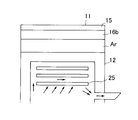
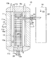
- FIG. 1 is a schematic longitudinal sectional view of a gas phase reaction apparatus according to a first embodiment of the present invention. It is the figure which expanded the principal part of the reaction apparatus of FIG. 1, and showed the reflector and the flow of gas typically. It is a schematic longitudinal cross-sectional view of the gaseous-phase reaction apparatus which concerns on the 2nd Embodiment of this invention.
- the gas phase reaction apparatus 10 includes a cylindrical container 11, a reaction container 12 housed in the container 11, a container 11 and a reaction container 12. And a heater (heating means) 13 for heating the inside of the reaction vessel 12 and a quenching tower (quenching device) 14 connected to the reaction vessel 12.
- the storage container 11 has a heat-insulating brick layer 16a lined on the inner surface of the bottom and periphery of the steel outer cylinder container 15, and a heat insulating material layer 16b such as an alumina heat insulating material lined on the upper inner surface of the outer cylinder container 15, respectively.
- a heat insulating container which includes a cylindrical body portion 11a, a canopy portion 11b provided at the upper end of the body portion 11a, and a bottom plate portion 11c provided at the lower end of the body portion 11a, and is provided on the outer surface of the body portion 11a.
- the supported support member 11d is supported on the foundation and installed with its axis centered up and down.
- a through hole 11e is formed at the center of the bottom plate portion 11c, and a through hole 11f is formed at a predetermined position on the upper edge side of the body portion 11a.
- the reaction vessel 12 is supported by a lower portion inside the storage container 11 and has a substantially cylinder made of carbon that is stored with a space between the inner wall of the body 11a of the storage container 11 and the canopy 11b with the axis centered vertically.
- a plurality of substantially cylindrical members of a predetermined height are arranged in a substantially coaxial manner up and down in a cylindrical reaction vessel, and the butted ends are fastened by screwing or fastening by an external fitting ring.
- the cylindrical body (tubular portion) 17 is tightly fastened by means, a carbon bottom plate member (bottom portion) 18 is provided at the lower end portion of the cylindrical body 17, and a carbon canopy member (ceiling portion) is provided at the upper end portion of the cylindrical body 17.
- the plate portion) 19 is a cylindrical container that is airtightly fastened by fastening means similar to those of the cylindrical members.
- the reaction vessel 12 has a bottom plate member 18 fitted into the through hole 11e of the bottom plate portion 11c of the storage vessel 11 and supported by the storage vessel 11.
- the bottom plate member 18 has a flow of the raw material gas to the reaction vessel 12.
- a through hole serving as the inlet 12a is formed, and an inflow pipe 20 connected to an evaporator (not shown) is connected to and attached to the through hole.
- the canopy member 19 is made of a closing member, and a through hole serving as the outlet 12b of the reaction vessel 12 is formed on the side surface of the cylindrical member of the cylindrical body 17 close to the canopy member 19, and a reaction product gas extraction pipe is inserted into the through hole. 21 is attached.
- the extraction pipe 21 is further inserted into the through hole 11 f of the storage container 11 and extends substantially horizontally to the outside of the storage container 11, and is connected to the quenching tower 14.
- the heater 13 is a set of two whose front ends are electrically connected to each other, and is vertically spaced with a space in the circumferential direction of the reaction vessel 12 in a space between the inner wall of the trunk portion 11 a of the containing vessel 11 and the reaction vessel 12.
- a plurality of long-bar-shaped carbon-made heating elements 13a disposed, and a plurality of sets of electrodes 13b that are connected to the respective base ends of the heating elements 13a and transfer electric power to the heating elements 13a. It becomes.
- the base end side of the heating element 13 a is supported on the canopy 11 b of the storage container 11 via a heat insulating material or the like, and the distal end side of the heating element 13 a is suspended to the vicinity of the bottom plate part 11 c of the storage container 11.
- the inside of the storage container 11 is filled with argon Ar as an inert gas, the inert gas is present around and above the reaction container 12, and when the heater 13 is applied, the heating element 13a is heated,
- the reaction vessel 12 is heated to about 1300 ° C. from the outer periphery and the upper side together with the inert gas.
- the quenching tower 14 instantaneously cools the reaction product gas mainly composed of a mixture of trichlorosilane and hydrogen chloride extracted from the extraction pipe 21 of the reaction vessel 12, and is disposed adjacent to the container 11.
- a steel cylindrical tower main body 22, a spray device 23 provided with a nozzle attached to the tower main body 22 and spraying the cooling liquid inside the tower main body 22, and the cooling liquid accumulated in the tower main body 22 are taken out.
- a pump (not shown) that circulates in the spray device 23, a cooling device (not shown) that cools the coolant, and a conduit (not shown) for taking out the reaction product gas after quenching from the top of the quenching tower 14 are provided. To do.
- a reaction product gas introduction pipe 24 into which the extraction pipe 21 of the reaction vessel 12 is inserted is provided substantially horizontally on the side wall of the tower main body 22, and the tip of the extraction pipe 21 extends to the inside of the tower main body 22.
- the coolant is sprayed from the top to the bottom with respect to the reaction product gas flowing out from the extraction pipe 21.
- a reflection plate (reflecting member) 25 for directing the flow of the reaction product gas toward the outlet 12b is provided in the reaction vessel 12 in the vicinity of the outlet 12b of the reaction vessel. It has been.
- a plurality of reflection plates 25 (three in the illustrated example) are arranged on the canopy member 19 side of the outlet 12b of the reaction vessel 12 and arranged in the vertical direction with a space between the reflection plate 25 and the inner surface of the canopy member 19.
- Each of the reflecting plates 25 is made of a disk-shaped carbon member having an outer diameter smaller than the inner diameter of the portion of the reaction vessel 12 where the reflecting plate 25 is installed.
- the thickness of the reflecting plate 25, the number of the reflecting plates 25, and the clearance between the reflecting plate 25 and the inner wall surface of the reaction vessel 12 are set so that the heat transfer efficiency in the reaction vessel 12 is as high as possible.
- the reflecting plate 25 may be disposed substantially horizontally as in the illustrated example, or may be disposed in a state of being inclined downward in a direction away from the outflow port 12b.
- the installation method of the reflecting plate 25 is arbitrary, and as shown in the example shown in the drawing, the reflecting plate 25 is arranged around the side inner surface of the canopy member 19 of the reaction vessel 12 or the inner peripheral surface of the cylindrical body 17 according to the vertical position of the reflecting plate 25.
- a plurality of support members 26a are attached so as to be spaced apart from each other (or the corresponding cylindrical member is manufactured in advance as having a support portion), and the lowermost reflector 25 is placed thereon, and the lowermost Recesses are respectively formed at corresponding positions on the upper surface of the reflection plate 25 and the lower surface of the reflection plate 25 that is over the reflection plate 25, and a bar-like spacer member 26b is fitted into the recess on the lowermost reflection plate 25,
- the second reflector 25 is attached by placing the next reflector 25 on the top and fitting the upper end of the spacer member 26b into the recess on the lower surface thereof.
- the third reflector 25 can also be attached. it can.
- the support member may be suspended from the canopy member 19 of the reaction vessel 12 and the reflection plate 25 may be attached thereto. Needless to say, the support member 26a and the spacer member 26b here are also carbon members.
- the present inventors verified the installation effect of the reflection plate 25 installed in the reaction vessel 12 as described above. As a result, it has been found that the heat transfer efficiency in the reaction vessel 12 is significantly improved when the reflector 25 is provided.
- a predetermined clearance for example, between the reflection plate 25 and the wall surface of the reaction vessel 12.
- the number of the reflectors 25 may be one, but if the number is increased to two or three, the gas temperature can be suppressed from decreasing and the outlet gas temperature can be increased. However, due to the structure of the reaction vessel 12, the number of installation is up to several.
- a graphite material having excellent airtightness is preferable, and in particular, the strength is high because of the fine particle structure, and the characteristics such as thermal expansion are the same in any direction. It is preferable to use isotropic high-purity graphite that is also excellent in heat resistance and corrosion resistance. Further, carbon is subjected to thinning or embrittlement of the structure as shown below due to hydrogen supplied into the reaction vessel or water generated by hydrogen combustion. C + 2H 2 ⁇ CH 4 C + H 2 O ⁇ H 2 + CO C + 2H 2 O ⁇ 2H 2 + CO 2 In order to prevent this, a silicon carbide film is preferably formed on the surface of the carbon member.
- the method for forming the silicon carbide film is not particularly limited, but typically it can be formed by vapor deposition by a CVD method.
- a method using a mixed gas of a silicon halide compound such as tetrachlorosilane or trichlorosilane and a hydrocarbon compound such as methane or propane, or methyl Silicon carbide is deposited on the surface of a heated carbon member while thermally decomposing a halogenated silicon compound such as trichlorosilane, triphenylchlorosilane, methyldichlorosilane, dimethyldichlorosilane, and trimethylchlorosilane with hydrogen.
- the thickness of the silicon carbide coating is preferably 10 to 500 ⁇ m, more preferably 30 to 300 ⁇ m. If the thickness of the silicon carbide coating is 10 ⁇ m or more, the corrosion of the carbon member due to hydrogen, water, methane, etc. existing in the reaction vessel can be sufficiently suppressed, and if it is 500 ⁇ m or less, the silicon carbide coating is cracked. Cracking of the structure of the carbon member is not promoted.
- a mixed gas of tetrachlorosilane and hydrogen gasified by the evaporator is introduced into the reaction vessel 12 from the inlet 12a at a predetermined introduction flow rate.
- the reaction vessel 12 is heated from the outside by the heater 13, but when the outer side surface of the cylindrical body 17 of the reaction vessel 12 is heated, heat is transferred from the outer surface to the inner surface by conduction heat transfer, and the cylinder
- the inner wall surface of the body 17 becomes high temperature, and the inside of the reaction vessel 12 is heated to a high temperature of about 700 to 1400 ° C. by radiant heat transfer or the like.
- the gas flow flowing in the reaction vessel 12 is heated, the thermal equilibrium reaction of the formula (1) proceeds in the forward direction, and the introduced source gas becomes a reaction product gas mainly composed of trichlorosilane and hydrogen chloride, It is led from the outlet 12 b to the quenching tower 14 through the extraction pipe 21.
- the heat transfer process related to the reflector 25 will be described in some detail.
- the heating element 13a When the heater 13 is applied, the heating element 13a is heated, and radiant heat from the heating element 13a causes heat transfer.
- the outer surface of the reaction vessel 12 is heated together with the argon Ar. Since the heating elements 13a of the heater 13 are arranged at equal intervals in the circumferential direction outside the cylindrical body 17 of the reaction vessel 12, the outer surface of the cylindrical body 17 of the reaction vessel 12 is heated to a high temperature together with the surrounding argon gas Ar.
- the canopy member 19 of the reaction vessel 12 and the argon gas Ar in the vicinity thereof are not heated as much as the cylindrical body 17 and the surrounding argon gas Ar, and rather rather to the outside from the canopy member 19 of the reaction vessel 12. Heat dissipation is occurring.
- the reaction vessel 12 is made of carbon, when the outer surface of the cylindrical body 17 is heated, heat is transferred to the inner surface of the reaction vessel 12 by conduction heat transfer, and then radiant heat transfer from the inner surface of the reaction vessel 12.
- the reflector 25 is heated one after another by the above, but as described above, since heat radiation to the outside is generated from the canopy member 19 of the reaction vessel 12, only the lowest reflector 25 in the reflector 25 is present. The temperature becomes higher than the gas temperature, the heat transfer area is increased by the lowermost reflecting plate 25, and the amount of heat transfer to the gas flow is increased. Further, since the lowermost reflector 25 is disposed at a position slightly above the outlet 12b in a state of crossing the reaction vessel 12, the gas flow flowing upward from below collides with this and is branched.
- the reflection plate 25 is provided inside the reaction vessel 12 heated by the heater 13, and the heat transfer efficiency in the reaction vessel 12 is radiant heat transfer by the reflection plate 25. Improved by convective heat transfer. Therefore, compared with the case where the reflecting plate 25 is not provided, the outlet gas temperature can be kept high, and a high reaction yield can be achieved. Further, since the extraction pipe 21 is provided at the outlet 12 b of the reaction vessel 12 and connected to the quenching tower 14, the reaction product gas is extracted from the extraction pipe 21 together with the effect of the reflector 25 near the outlet 12 b. Since the reaction product gas is instantaneously cooled in the quenching tower 14 from this state, the equilibrium reaction is frozen and the reverse reaction is effectively prevented.
- FIG. 3 is a schematic cross-sectional view showing a gas phase reactor according to the second embodiment of the present invention.
- a plurality of disc-shaped carbon porous plates 27 having a predetermined hole area ratio, hole diameter, and number of holes are provided in the reaction vessel 12 and are spaced apart in the height direction of the cylindrical body 17. It is arranged with a gap.
- These perforated plates 27 are basically arranged at substantially equal intervals and substantially horizontally over substantially the entire length of the cylindrical body 17, but a predetermined clearance is maintained between the inner wall surface of the reaction vessel 12.
- Each of the perforated plates 27 is basically manufactured or arranged so that the holes of the one perforated plate 27 and the perforated plates 27 positioned above and below the perforated plate 27 are not coaxial.
- the installation method of the porous plate 27 is arbitrary, and can be installed by the same method as the reflection plate 25.
- recesses are formed at a plurality of locations in the circumferential direction on the upper and lower surfaces of the perforated plate 27, and the upper and lower ends of a rod-like support member 28 are fitted between the recesses, and the perforated plate 27 is sequentially moved upward from the bottom of the reaction vessel 12.
- Reflecting plate 25 in the illustrated example is stacked and installed.
- a plurality of support edges may be attached to the inner wall surface of the reaction vessel 12 at intervals in the circumferential direction, and the porous plate 27 and the reflection plate 25 may be placed thereon.
- the inventors verified the installation effect of the porous plate 27 installed in the reaction vessel 12 as described above. As a result, it was found that when the porous plate 27 is provided, the heat transfer efficiency in the reaction vessel 12 can be significantly improved. Moreover, it turned out that what has the following characteristics as the porous plate 27 to be used is preferable.
- the thickness t of the porous plate is preferably 10 mm ⁇ t ⁇ 60 mm, and is not limited to this as long as there is no problem in manufacturing.
- the aperture ratio of the perforated plate is the ratio of the total cross-sectional area of the perforations to the total area in plan view including the perforations of the perforated plate. The distance from the wall.
- the mixed gas of tetrachlorosilane and hydrogen is heated to a high temperature while passing through the reaction vessel 12 in the same manner as in the first embodiment, so that trichlorosilane and chloride are mixed. It becomes a reaction product gas containing hydrogen as a main component, and is led from the outlet 12b to the quenching tower 14 through the extraction pipe 21.
- the reflecting plate 25 but also the porous plate 27 is disposed in the reaction vessel 12, so that the heat transfer efficiency in the reaction vessel 12 is further improved.
- the raw material gas and the reaction product gas flow in a mixed manner, and convective heat transfer occurs around the hole of the perforated plate 27, which also heats the gas. Since the porous plate 27 heated in this way is disposed in the reaction vessel 12, the heat transfer area in the reaction vessel 12 increases and convection heat transfer occurs. As a result, the amount of heat transfer to the gas flow increases, and the porous Since the flow rate of the gas flow increases when the gas flow passes through the hole of the plate 27, the heat transfer efficiency in the vicinity of the hole of the perforated plate 27 increases.
- the porous plate 27 is provided in addition to the reflection plate 25 inside the reaction vessel 12 heated by the heater 13, so that the heat transfer efficiency in the reaction vessel 12 is further improved. It is done. Therefore, compared with the case where the reflecting plate 25 and the porous plate 27 are not provided, the outlet gas temperature can be kept high, and a high reaction yield can be achieved.
- the reflecting plate 25 and the porous plate 27 are installed in the reaction vessel 12, but a structure in which the reflecting plate 25 is combined with a baffle plate or other molded filler may be used.
- the reaction vessel 12 has a cylindrical shape with the same diameter in the vertical direction, but the vicinity of the outflow port 12b or the vicinity of the inflow port 12a may be a reduced diameter portion.
- this Example is for confirming the installation effect about the typical example of a reflecting plate, Comprising:
- the structure of a reflecting plate is not limited by this Example.
- Example 1 The installation effect of the reflector was verified in the following reactor.
- Container Outer cylinder container: SUS304, 19 mm thick Thermal insulation layer: Alumina thermal insulation, 29 mm thickness Thermal insulation brick layer: Alumina brick, 500 mm thickness Inert gas layer: Argon, 163 mm thickness
- Reaction vessel Top plate: Carbon, 100mm thickness Inner diameter: 750mm
- the reflection plate three disc-shaped carbon plate materials having a thickness of 20 mm and a diameter of 65 cm ⁇ were prepared.
- the three reflectors were horizontally arranged with a support member at a distance from each other so that the lowermost reflector is located slightly above the outlet in the reaction vessel.
Landscapes
- Chemical & Material Sciences (AREA)
- Organic Chemistry (AREA)
- Inorganic Chemistry (AREA)
- Chemical Kinetics & Catalysis (AREA)
- Engineering & Computer Science (AREA)
- Physics & Mathematics (AREA)
- Thermal Sciences (AREA)
- Mechanical Engineering (AREA)
- General Engineering & Computer Science (AREA)
- Silicon Compounds (AREA)
- Physical Or Chemical Processes And Apparatus (AREA)
Abstract
伝熱効率を高く保ちながら、逆反応等をできるだけ防止して高い反応収率を達成することができる、特にクロロシランと水素の高温気相反応に適した反応装置が提供される。該反応装置は、流入口から供給される複数種の原料ガスを気相反応させて流出口から反応生成ガスとして排出する反応容器と、反応容器に付設されて反応容器の内部を加熱する加熱手段と、反応容器の内部に流出口に近接して設けられて反応生成ガスの流れを流出口に向ける反射部材とを具備してなる。
Description
本発明は気相反応装置に関する。
トリクロロシラン(SiHCl3)は、半導体、液晶パネル、太陽電池等の製造に用いられる特殊材料ガスである。近年、需要は順調に拡大し、エレクトロニクス分野で広く使用されるCVD材料として、今後も伸びが期待されている。
トリクロロシランは、テトラクロロシラン(SiCl4)に水素(H2)を付加させる以下の反応によって生成される。
SiCl4+H2→SiHCl3+HCl (1)
この反応は、熱平衡気相反応であり、ガス化したテトラクロロシランと水素からなる原料ガスを約700~1400℃の高温に加熱することにより正反応が起こり、トリクロロシランが得られる。
SiCl4+H2→SiHCl3+HCl (1)
この反応は、熱平衡気相反応であり、ガス化したテトラクロロシランと水素からなる原料ガスを約700~1400℃の高温に加熱することにより正反応が起こり、トリクロロシランが得られる。
従来、この種の気相反応の反応装置としては、例えば特許文献1に記載されているような装置が知られている。この装置は、周囲を発熱体によって囲まれると共に同心配置の管によって形成された外室と内室からなる反応室と、反応室の上部に設けられて外室と内室を相互に連通させるダイバータと、反応室の下部に設けられて外室に導入される原料ガスと内室から導出される反応生成ガスとの熱交換を行う熱交換器とを具備してなる。原料ガスは熱交換器を通して予熱されて外室に供給され、外室からダイバータを経て内室を流れる間に反応が進行し、反応生成ガスとして熱交換器によって冷却されて排出される。
しかしながら、上記のような反応装置では、反応室がダイバータを介した二重室とされ、ガスが外室と内室の順に上下に往復させられる構造とされているため、反応室の出口ガス温度が低下してしまう問題があった。また、反応生成ガスの冷却を急速に行えないため、生成したトリクロロシランがテトラクロロシランに逆反応してしまう虞があり、高い反応収率が得られないという問題もある。
本発明の一目的は、従来技術における不具合を少なくとも部分的に解消した気相反応装置を提供することにある。
本発明の他の目的は、伝熱効率を高く保つ気相反応装置を提供することにある。
本発明の更なる目的は、逆反応等をできるだけ防止して高い反応収率を達成することができる気相反応装置、特にクロロシランと水素の高温気相反応に適した反応装置を提供することにある。
本発明の他の目的は、伝熱効率を高く保つ気相反応装置を提供することにある。
本発明の更なる目的は、逆反応等をできるだけ防止して高い反応収率を達成することができる気相反応装置、特にクロロシランと水素の高温気相反応に適した反応装置を提供することにある。
よって、本発明では、
流入口から供給される複数種の原料ガスを気相反応させて流出口から反応生成ガスとして排出する反応容器と、
反応容器に付設されて反応容器の内部を加熱する加熱手段と、
反応容器の内部に流出口に近接して設けられて反応生成ガスの流れを流出口に向ける反射部材と
を具備してなる気相反応装置が提供される。
流入口から供給される複数種の原料ガスを気相反応させて流出口から反応生成ガスとして排出する反応容器と、
反応容器に付設されて反応容器の内部を加熱する加熱手段と、
反応容器の内部に流出口に近接して設けられて反応生成ガスの流れを流出口に向ける反射部材と
を具備してなる気相反応装置が提供される。
ここで、反応容器は、高温気相反応に適した構造、材料からなるものであれば如何なるものでもよいが、容器の一側に流入口を備え、一側とは遠隔の他側に流出口を備え、流入口と流出口との間に所定の距離がとれる構造のものが好ましく、また加熱手段によって壁面が加熱されて反応容器内部に熱を伝達する材料から構成されるのが好ましい。
加熱手段は、反応容器の内部を加熱できる構造のものであれば、如何なるものでも構わないが、反応容器壁面を加熱して反応容器内部を高温加熱状態にする構造のものが好ましい。一態様では、反応容器を伝熱性に優れた材料で形成し、反応容器壁を直接加熱する構造とすることができる。他の態様では、反応容器を伝熱性に優れた材料で形成し、反応容器の外部にヒータを配して反応容器壁面を加熱する構造とすることができる。何れの場合も反応容器は、全体を収容容器に収容し、周囲とは断熱するのが好ましいが、特に後者の外部ヒータを設置する場合は、反応容器とヒータを配した収容容器内にはアルゴンのような不活性ガス等を充填しておくのが好ましい。
反射部材は、反応生成ガスの流れが当たるとこれを反射させ、反応生成ガスの流れを流出口に向け得る部材であれば、如何なるものでも構わないが、加熱手段が反応容器の内部を加熱する結果、反応容器の内部に配設されている反射部材自体も加熱され、反応容器内のガス流にその熱を移動させる伝熱部材であるのが好ましい。よって、反射部材は、好ましくは反応生成ガスの流れを受けて反射させ流れを流出口へ向ける板材であって、熱移動に適した材料から構成され、例えばカーボン製の板状体が好適に利用できる。
かかる気相反応装置では、反応容器の内部に流出口に近接して設けられて反応生成ガスの流れを流出口に向け得る反射部材を配設したので、反応容器中のガス流への伝熱効率を高く保つことができ、高い反応収率を達成することができる。よって、反応容器内に反射部材を配設しない場合に比して、出口ガス温度を高く保つことが可能になり、高い反応収率を達成することが可能となる。
一態様では、上記において、反応容器を、上下方向に延びる筒状部と、流入口を備え筒状部の下部に設けられた底部と、筒状部の上部に設けられた天板部とを具備し、筒状部の天板部に近接する位置に流出口が設けられたものとし、加熱手段を、反応容器の外部に配設されて反応容器の筒状部を加熱するヒータとし、反射部材を、流出口より天板部側に天板部の内表面との間に間隙を形成して略水平に配置された板状材からなるものとすることができる。
反応容器をこのような構造にすると、ガス流路を上下方向に往復させる場合に比して、構造が簡単である。また、反射部材を、上記のような位置に配置すると、反射部材と天板部との間の空間がガス流速の低いデッドスペースとなり、その結果、反射部材に当たって流出口へ向けて流れるガスの流速が反射部材を設けていない場合に比して向上し、反射部材からガス流への伝熱効率が向上する。また、ヒータが反応容器の筒状部を加熱する構造であり反応容器の天板部は筒状部ほど加熱されないため、天板部では反応容器外への放熱が生じているが、反応容器内の天板部側に反射部材を設けているため、ガス流が天板部に直接当たることがなく、ガス流の温度低下が防止される。
また他の態様では、上記において、反射部材を、上下方向に間隔をあけて配置した複数枚の板状材からなるものとすることができる。
ここで、板状材の位置は、最下位に位置する板状体が、反応容器の内部に流出口に近接して位置させられて反応生成ガスの流れを流出口に向け得るならば、他の板状体の位置は、最下位の板状体と反応容器の天板部内面までの空間内の何れの位置にあっても構わない。
ここで、板状材の位置は、最下位に位置する板状体が、反応容器の内部に流出口に近接して位置させられて反応生成ガスの流れを流出口に向け得るならば、他の板状体の位置は、最下位の板状体と反応容器の天板部内面までの空間内の何れの位置にあっても構わない。
反射部材をこのような構成とすると、放熱部となる天板部へガスが直接接触すること無く、反応室外へ導出されるため、反応生成ガスの温度低下を防止できる。また、板状体を複数設置することで、最下位の板状体はガス温度より高温となり、ガス温度の向上に寄与する。
また更なる態様では、上記において、反応容器と反射部材は、表面が炭化ケイ素被覆されたカーボン部材製とすることができる。カーボン部材製とするのは、かかる部材が耐熱性、耐熱衝撃性、耐食性等に優れるからであるが、後述するように、カーボン部材は反応容器内に供給される水素や、水素の燃焼により生成する水によって組織の減肉または脆化を受けてしまう。従って、トリクロロシラン製造プロセスにおいて長期にわたって使用するためには、表面に炭化ケイ素被膜処理を施すのが好ましい。
また別の態様によれば、上記において、気相反応装置は、金属製の外筒容器と外筒容器に内張りされた断熱層とを具備し内部に不活性ガスが封入された収容容器に、反応容器と加熱手段が収容されてなるのが好ましい。
かかる構成とすることによって、加熱手段から発生された熱を装置外部に逃がすことを極力防止することができ、また反応容器の加熱を極力均一に行わせることができる。
かかる構成とすることによって、加熱手段から発生された熱を装置外部に逃がすことを極力防止することができ、また反応容器の加熱を極力均一に行わせることができる。
更に別の態様によれば、本発明に係る気相反応装置は、複数種の原料ガスが、テトラクロロシランと水素を含み、反応生成ガスがトリクロロシランと塩化水素を含む反応系に特に好適に使用される。
ここで、原料ガスには、テトラクロロシランと水素以外の化学種が含まれていてもよく、また他の系からの循環液等も蒸発させて併せて供給されてもよい。また、反応生成ガスには、トリクロロシランと塩化水素以外の化学種、例えば未反応の原料成分やヘキサクロロジシラン等の高沸点物質、ジクロロシラン等の低沸点物質等が含まれうる。
ここで、原料ガスには、テトラクロロシランと水素以外の化学種が含まれていてもよく、また他の系からの循環液等も蒸発させて併せて供給されてもよい。また、反応生成ガスには、トリクロロシランと塩化水素以外の化学種、例えば未反応の原料成分やヘキサクロロジシラン等の高沸点物質、ジクロロシラン等の低沸点物質等が含まれうる。
更に本発明に係る気相反応装置においては、上記の種々の構成の何れか一に加えて、反応容器内の伝熱効率を更に高めるために多孔板のような伝熱部材を反応容器内に更に配置することができる。すなわち、反応容器の内部に多孔板のような伝熱部材を配設すると、加熱手段により反応容器が加熱されると、反応容器の壁体等からの輻射伝熱等により伝熱部材が加熱され、かかる伝熱部材からガス流への熱移動により反応容器中のガス流を更に加熱することができる上、伝熱部材によってその付近を流れるガス流の流速が高められるので、伝熱部材等からのガス流への伝熱効率が高くなり、また伝熱部材によりガス流が乱れて対流伝熱も生じる。よって、反応容器内におけるガス流への伝熱量が増加し、反応容器内において高い伝熱効率を、またひいては高反応収率を達成することができる。
本発明者等は、孔部等を通過するガスの流速、多孔板の開孔率、反応容器内壁と多孔板とのクリアランス、多孔板の厚みなどについて、実験的に最適な範囲を求めた。その結果、次のような範囲にすれば高い伝熱効率が得られることが知見された。すなわち、多孔板は、通過するガスの流速を2m/s以上とする多孔部を有してなるものとするのが好ましく、また25%以下の開孔率を有するものが好ましい。また多孔板は、多孔板と反応容器の内壁との間に、反応容器の内壁直径の6/1000~50/1000の範囲のクリアランスをあけて配設されたものが好ましく、また多孔板の孔部の孔径は、反応容器の内壁直径の25/1000以下で、孔数は開孔率が25%以下となる数であるのが好ましい。また、多孔板の厚さtは10mm≦t≦60mmが好ましい。製作加工上問題が無ければこの限りではない。
更に本発明に係る気相反応装置においては、上記の種々の構成の何れか一に加えて、反応容器から導出される反応生成ガスを急冷する急冷塔を備えるのが好ましい。
このような構成によって、反応生成ガスを可能な限り瞬時に冷却して平衡を凍結し、逆反応が起こるのを極力防止することができる。
すなわち、本発明の一態様では、
流入口から供給される複数種の原料ガスを気相反応させて流出口から反応生成ガスとして排出する反応容器と、
反応容器に付設されて反応容器の内部を加熱する加熱手段と、
反応容器の内部に流出口に近接して設けられて反応生成ガスの流れを流出口に向ける反射部材と、
反応容器に接続されて反応容器の流出口から導出される反応生成ガスを急冷する急冷装置と
を具備してなる気相反応装置が提供される。
このような構成によって、反応生成ガスを可能な限り瞬時に冷却して平衡を凍結し、逆反応が起こるのを極力防止することができる。
すなわち、本発明の一態様では、
流入口から供給される複数種の原料ガスを気相反応させて流出口から反応生成ガスとして排出する反応容器と、
反応容器に付設されて反応容器の内部を加熱する加熱手段と、
反応容器の内部に流出口に近接して設けられて反応生成ガスの流れを流出口に向ける反射部材と、
反応容器に接続されて反応容器の流出口から導出される反応生成ガスを急冷する急冷装置と
を具備してなる気相反応装置が提供される。
更に好ましい態様では、本発明に係る気相反応装置は、
上下方向に延びる筒状部と、流入口を備え筒状部の下部に設けられた底部と、筒状部の上部に設けられた天板部とを具備し、流入口から供給される複数種の原料ガスを気相反応させて、筒状部の天板部に近接する位置に設けられた流出口から反応生成ガスとして排出する反応容器と、
反応容器の外部に配設されて反応容器の筒状部を加熱する加熱手段と、
反応容器の内部に、流出口より天板部側に天板部の内表面との間に間隙を形成して設けられて反応生成ガスの流れを流出口に向ける伝熱材からなる反射部材と、
反応容器に接続されて反応容器の流出口から導出される反応生成ガスを急冷する急冷装置と
を具備してなる気相反応装置が提供される。
上下方向に延びる筒状部と、流入口を備え筒状部の下部に設けられた底部と、筒状部の上部に設けられた天板部とを具備し、流入口から供給される複数種の原料ガスを気相反応させて、筒状部の天板部に近接する位置に設けられた流出口から反応生成ガスとして排出する反応容器と、
反応容器の外部に配設されて反応容器の筒状部を加熱する加熱手段と、
反応容器の内部に、流出口より天板部側に天板部の内表面との間に間隙を形成して設けられて反応生成ガスの流れを流出口に向ける伝熱材からなる反射部材と、
反応容器に接続されて反応容器の流出口から導出される反応生成ガスを急冷する急冷装置と
を具備してなる気相反応装置が提供される。
10 気相反応装置
11 収容容器
11a 胴部
11b 天蓋部
11c 底板部
11d 支持部材
11e,11f 貫通孔
12 反応容器
12a 流入口
12b 流出口
13 ヒータ(加熱手段)
13a 発熱体
13b 電極
14 急冷塔(急冷装置)
15 外筒容器
16a,16b 断熱煉瓦層,断熱材層(断熱層)
17 円筒体(筒状部)
18 底板部材(底部)
19 天蓋部材(天板部)
20 流入管
21 抜き出し管
22 塔本体
23 スプレー装置
24 反応生成ガス導入管
25 反射板(反射部材)
26a 支持部材
26b スペーサ部材
27 多孔板
28 支持部材
11 収容容器
11a 胴部
11b 天蓋部
11c 底板部
11d 支持部材
11e,11f 貫通孔
12 反応容器
12a 流入口
12b 流出口
13 ヒータ(加熱手段)
13a 発熱体
13b 電極
14 急冷塔(急冷装置)
15 外筒容器
16a,16b 断熱煉瓦層,断熱材層(断熱層)
17 円筒体(筒状部)
18 底板部材(底部)
19 天蓋部材(天板部)
20 流入管
21 抜き出し管
22 塔本体
23 スプレー装置
24 反応生成ガス導入管
25 反射板(反射部材)
26a 支持部材
26b スペーサ部材
27 多孔板
28 支持部材
以下、本発明の気相反応装置の一実施形態について、図面を参照して説明する。
図1に示す実施形態では、気相反応装置10は、円筒状の収容容器11と、収容容器11の内部に収容された反応容器12と、収容容器11の内部に収容されると共に反応容器12に付設されて反応容器12の内部を加熱するヒータ(加熱手段)13と、反応容器12に接続された急冷塔(急冷装置)14とを具備する。
図1に示す実施形態では、気相反応装置10は、円筒状の収容容器11と、収容容器11の内部に収容された反応容器12と、収容容器11の内部に収容されると共に反応容器12に付設されて反応容器12の内部を加熱するヒータ(加熱手段)13と、反応容器12に接続された急冷塔(急冷装置)14とを具備する。
収容容器11は、鋼製の外筒容器15の底部及び周部の各内面に断熱煉瓦層16aが、外筒容器15の上部内面にアルミナ製断熱材等の断熱材層16bがそれぞれ内張りされた断熱容器で、円筒状の胴部11aと、胴部11aの上端に設けられた天蓋部11bと、胴部11aの下端に設けられた底板部11cとからなり、胴部11aの外側面に設けられた支持部材11dが基礎上に支持されて軸心を上下に向けて設置されている。底板部11cの中心に貫通孔11eが形成され、胴部11aの上縁側の所定位置に貫通孔11fが形成されている。
反応容器12は、収容容器11の内部に下部が支持されて軸心を上下に向け収容容器11の胴部11a内壁と天蓋部11bとの間に空間をあけて収容されたカーボン製の略円筒状の反応容器で、所定高さの複数の略円筒部材を、端部同士を突き合わせて略同軸状に上下に配し、突き合わせ端部を、螺合締結や外嵌合リングによる締結等の締結手段により気密的に締結して円筒体(筒状部)17とし、円筒体17の下端部にカーボン製の底板部材(底部)18を、円筒体17の上端部にカーボン製の天蓋部材(天板部)19を、それぞれ円筒部材同士と同様の締結手段で気密的に締結した円筒状容器である。反応容器12は、その底板部材18が収容容器11の底板部11cの貫通孔11eに嵌め込まれて収容容器11に支持されており、その底板部材18には、反応容器12への原料ガスの流入口12aとなる貫通孔が形成され、該貫通孔に図示しない蒸発缶に接続された流入管20が連通されて取り付けられている。天蓋部材19は閉塞部材からなり、反応容器12の流出口12bとなる貫通孔は、天蓋部材19に近接する円筒体17の円筒部材の側面に形成され、該貫通孔に反応生成ガスの抜き出し管21が取り付けられている。該抜き出し管21は、更に収容容器11の貫通孔11fに挿通されて収容容器11の外部まで略水平に延び、急冷塔14に接続されている。
ヒータ13は、先端側が電気的に互いに接続された二本一組で、収容容器11の胴部11a内壁と反応容器12との間の空間に反応容器12の周方向に間隔をあけて鉛直に配設された長尺棒状のカーボン製の複数組の発熱体13aと、発熱体13aの各基端側に連結されて発熱体13aへの電力の授受を行う複数組の電極13bとを具備してなる。発熱体13aの基端側は、収容容器11の天蓋部11bに断熱材等を介して支持され、発熱体13aの先端側は収容容器11の底板部11cの近くまで垂下させられている。
収容容器11の内部には不活性ガスとしてアルゴンArが充填され、反応容器12の周りと上部には不活性ガスが存在しており、ヒータ13が印加されると、発熱体13aが加熱され、不活性ガスと共に反応容器12が外周及び上方から例えば1300℃程度に加熱される構成とされている。
収容容器11の内部には不活性ガスとしてアルゴンArが充填され、反応容器12の周りと上部には不活性ガスが存在しており、ヒータ13が印加されると、発熱体13aが加熱され、不活性ガスと共に反応容器12が外周及び上方から例えば1300℃程度に加熱される構成とされている。
急冷塔14は、反応容器12の抜き出し管21から抜き出されるトリクロロシランと塩化水素の混合物を主成分とする反応生成ガスを瞬時に冷却するもので、収容容器11に隣接して配設された鋼製円筒状の塔本体22と、塔本体22に付設されて塔本体22の内部に冷却液を噴霧するノズルを備えたスプレー装置23と、塔本体22の内部に溜まった冷却液を取り出してスプレー装置23に循環させるポンプ(図示略)と、冷却液を冷却する冷却装置(図示略)と、急冷塔14の頂部から急冷後の反応生成ガスを取り出すための導管(図示略)とを具備する。塔本体22の側壁には反応容器12の抜き出し管21が挿入される反応生成ガス導入管24が略水平に設けられ、抜き出し管21の先端は塔本体22の内部まで延び、スプレー装置23のノズルからの冷却液が抜き出し管21から流出する反応生成ガスに対して上から下に向けて噴霧されるように構成されている。
本実施形態に係る気相反応装置10では、反応容器12の内部に、反応容器の流出口12bに近接して、反応生成ガスの流れを流出口12bに向ける反射板(反射部材)25が設けられている。反射板25は、反応容器12の流出口12bより天蓋部材19側で、天蓋部材19の内表面との間に間隔をあけて上下方向に並べて複数枚(図示例では3枚)が配設されており、何れの反射板25も、反応容器12の当該反射板25が設置される部分の内径よりも小なる外径の円板状のカーボン製部材からなる。反射板25の厚み、反射板25の枚数、反射板25と反応容器12の内壁面との間のクリアランスは、反応容器12内の伝熱効率が可能な限り高くなるように設定される。また、反射板25は、図示例のように略水平に配置されてもよいし、流出口12bから離れる方向に下方に傾斜させた状態で配置することも可能である。
ここで、反射板25の設置方法は、任意であり、図示例の如く、反射板25の上下位置に応じて反応容器12の天蓋部材19の側内面部もしくは円筒体17の内周面に周方向に離間して複数の支持部材26aを取付け(あるいは該当する円筒部材を予め支持部を備えたものとして製作する)、その上に最下位の反射板25を載置すると共に、該最下位の反射板25の上面とその上にくる反射板25の下面の対応する位置にそれぞれ凹所を形成しておき、最下位の反射板25の上の凹所に棒状スペーサ部材26bを嵌入させ、その上に次の反射板25を配してその下面の凹所にスペーサ部材26bの上端を嵌入させて二枚目の反射板25を取付け、同様にして三枚目の反射板25も取り付けることができる。あるいは、反応容器12の天蓋部材19から支持部材を垂下し、これに反射板25を取り付けてもよい。尚、ここでの支持部材26aやスペーサ部材26bもカーボン製部材とすることは言うまでもない。
上記のようにして反応容器12の内部に設置された反射板25について、本発明者等は、後記する実施例に示すように、その設置効果を検証した。その結果、反射板25を設けると、反応容器12における伝熱効率が有意に向上させられることが知見された。本発明者等が得た結果をここでまとめると、反応容器12と反射板25の熱膨張に差が生じうるため、反射板25と反応容器12の壁面との間には所定のクリアランス(例えば反応容器12の内壁直径の1/10程度)を取っておくことが必要であるが、伝熱効率向上の観点からは反応容器12の内壁との間のクリアランスはできるだけ小さいことが望ましい。
反射板25の枚数は1枚でもよいが、2枚、3枚と増やすとガス温度の低下が抑制でき、かつ出口ガス温度が上昇する。但し、反応容器12の構造上、設置数は数枚までである。
反射板25の枚数は1枚でもよいが、2枚、3枚と増やすとガス温度の低下が抑制でき、かつ出口ガス温度が上昇する。但し、反応容器12の構造上、設置数は数枚までである。
上記において、カーボン製部材を構成する材質としては、気密性に優れた黒鉛材が好ましく、特に、微粒子構造のため強度が高く、熱膨張等の特性がどの方向に対しても同一であることから耐熱性および耐食性にも優れている等方性高純度黒鉛を用いることが好ましい。
更に、カーボンは、反応容器内に供給される水素や、水素の燃焼により生成する水によって、以下に示すように、組織の減肉または脆化を受けてしまう。
C+2H2→CH4
C+H2O→H2+CO
C+2H2O→2H2+CO2
これを防止するために、上記カーボン製の部材の表面には炭化ケイ素被膜が形成されるのが好ましい。
更に、カーボンは、反応容器内に供給される水素や、水素の燃焼により生成する水によって、以下に示すように、組織の減肉または脆化を受けてしまう。
C+2H2→CH4
C+H2O→H2+CO
C+2H2O→2H2+CO2
これを防止するために、上記カーボン製の部材の表面には炭化ケイ素被膜が形成されるのが好ましい。
炭化ケイ素被膜の形成方法は、特に制限はないが、典型的にはCVD法により蒸着させて形成することができる。CVD法により所定部材の表面に炭化ケイ素被膜を形成するには、例えば、テトラクロロシラン又はトリクロロシランのようなハロゲン化珪素化合物とメタンやプロパンなどの炭化水素化合物との混合ガスを用いる方法、またはメチルトリクロロシラン、トリフェニルクロロシラン、メチルジクロロシラン、ジメチルジクロロシラン、トリメチルクロロシランのような炭化水素基を有するハロゲン化珪素化合物を水素で熱分解しながら、加熱されたカーボン製部材の表面に炭化ケイ素を堆積させる方法を用いることができる。炭化ケイ素被膜の厚みは、10~500μmとすることが好ましく、30~300μmであればさらに好ましい。炭化ケイ素被膜の厚みが10μm以上であれば、反応容器内に存在する水素、水、メタン等によるカーボン製部材の腐食を十分に抑制でき、また、500μm以下であれば、炭化ケイ素被膜のひび割れやカーボン製部材の組織の割れが助長されることもない。
次に、本実施形態に係る気相反応装置10の作用を説明する。
蒸発缶でガス化されたテトラクロロシランと水素の混合ガスは流入口12aから所定の導入流速で反応容器12中に導入される。反応容器12は、ヒータ13によって外部から加熱されるが、反応容器12の円筒体17の側面外表面が加熱されると、その外表面から内表面に向けて伝導伝熱によって熱が伝わり、円筒体17の内壁表面が高温になり、反応容器12の内部が輻射伝熱等によって約700~1400℃の高温に加熱される。その結果、反応容器12内を流れるガス流が加熱され、式(1)の熱平衡反応が正方向に進行し、導入された原料ガスがトリクロロシランと塩化水素を主成分とする反応生成ガスとなり、流出口12bから抜き出し管21を介して急冷塔14に導かれる。
蒸発缶でガス化されたテトラクロロシランと水素の混合ガスは流入口12aから所定の導入流速で反応容器12中に導入される。反応容器12は、ヒータ13によって外部から加熱されるが、反応容器12の円筒体17の側面外表面が加熱されると、その外表面から内表面に向けて伝導伝熱によって熱が伝わり、円筒体17の内壁表面が高温になり、反応容器12の内部が輻射伝熱等によって約700~1400℃の高温に加熱される。その結果、反応容器12内を流れるガス流が加熱され、式(1)の熱平衡反応が正方向に進行し、導入された原料ガスがトリクロロシランと塩化水素を主成分とする反応生成ガスとなり、流出口12bから抜き出し管21を介して急冷塔14に導かれる。
ここで、図2も適宜参照しながら、反射板25に関連する伝熱プロセスを若干詳しく説明すると、ヒータ13が印加されると、発熱体13aが加熱され、発熱体13aからの輻射伝熱によりアルゴンArと共に反応容器12の外面が加熱される。
ヒータ13の発熱体13aは反応容器12の円筒体17の外部に周方向に等間隔に配設されているので、反応容器12の円筒体17の外表面はその周囲のアルゴンガスArと共に高温に加熱されるが、反応容器12の天蓋部材19とその付近のアルゴンガスArは、円筒体17とその周囲のアルゴンガスArほどは加熱されず、反応容器12の天蓋部材19からはむしろ外部への放熱が生じている。
ヒータ13の発熱体13aは反応容器12の円筒体17の外部に周方向に等間隔に配設されているので、反応容器12の円筒体17の外表面はその周囲のアルゴンガスArと共に高温に加熱されるが、反応容器12の天蓋部材19とその付近のアルゴンガスArは、円筒体17とその周囲のアルゴンガスArほどは加熱されず、反応容器12の天蓋部材19からはむしろ外部への放熱が生じている。
反応容器12はカーボン製であるため、円筒体17の外表面が加熱されると、伝導伝熱により、反応容器12の内表面に熱が伝わり、ついで反応容器12の内表面からの輻射伝熱により反射板25が次々と加熱されるが、上述のように、反応容器12の天蓋部材19からは外部への放熱が生じているので、反射板25の中で最下位の反射板25のみがガス温度以上となり、この最下位の反射板25の分だけ伝熱面積が増加し、ガス流への伝熱量が高まる。
また反射板25は、反応容器12を横断した状態で流出口12bより若干上方部位に最下位のものが配置されているため、下方から上方に流れてきたガス流がこれに衝突し、分岐されて流出口12bへ向けて流れるが、その際、最下位反射板25の上方部分にはガス流の流速の低いデッドスペースができるので、放熱状態にある天蓋部材19にガス流が直接吹き付けられることがなく、反応生成ガスの温度低下が効果的に防止され、更に反射板25付近の流速が上昇し、反射板25付近の伝熱効率が高まる。その結果、出口ガス温度が上昇する。
また反射板25は、反応容器12を横断した状態で流出口12bより若干上方部位に最下位のものが配置されているため、下方から上方に流れてきたガス流がこれに衝突し、分岐されて流出口12bへ向けて流れるが、その際、最下位反射板25の上方部分にはガス流の流速の低いデッドスペースができるので、放熱状態にある天蓋部材19にガス流が直接吹き付けられることがなく、反応生成ガスの温度低下が効果的に防止され、更に反射板25付近の流速が上昇し、反射板25付近の伝熱効率が高まる。その結果、出口ガス温度が上昇する。
このように、本実施形態における気相反応装置10では、ヒータ13によって加熱される反応容器12の内部に反射板25が設けられ、反応容器12内における伝熱効率が反射板25による輻射伝熱と対流伝熱によって向上させられる。よって、反射板25を設けていない場合に比して、出口ガス温度を高く保つことが可能になり、高い反応収率を達成することが可能となる。
また、反応容器12の流出口12bに抜き出し管21を設け、急冷塔14に接続したので、流出口12b付近の反射板25の効果も相俟って、反応生成ガスは抜き出し管21から抜き出される状態では十分に加熱された状態にあり、この状態から急冷塔14において反応生成ガスを瞬時に冷却するので、平衡反応が凍結され、逆反応が効果的に防止される。
また、反応容器12の流出口12bに抜き出し管21を設け、急冷塔14に接続したので、流出口12b付近の反射板25の効果も相俟って、反応生成ガスは抜き出し管21から抜き出される状態では十分に加熱された状態にあり、この状態から急冷塔14において反応生成ガスを瞬時に冷却するので、平衡反応が凍結され、逆反応が効果的に防止される。
図3は本発明の第2実施形態に係る気相反応装置を示す概略断面図であり、第1実施形態と同一の構成については同一の符号を付して説明を省略する。
本実施形態においては、反応容器12の内部に、所定の開孔率、孔径、孔数を有する円板状のカーボン製の多孔板27が、複数枚、その円筒体17の高さ方向に間隔をあけて配設されている。これら多孔板27は、円筒体17の高さ方向の略全長にわたって基本的には等間隔にかつ略水平に配置されるが、反応容器12の内壁面との間には所定のクリアランスが保たれ、また各多孔板27は、基本的には、一の多孔板27とその上下に位置する多孔板27との孔部が同軸にはならないように製作され又は配置される。
本実施形態においては、反応容器12の内部に、所定の開孔率、孔径、孔数を有する円板状のカーボン製の多孔板27が、複数枚、その円筒体17の高さ方向に間隔をあけて配設されている。これら多孔板27は、円筒体17の高さ方向の略全長にわたって基本的には等間隔にかつ略水平に配置されるが、反応容器12の内壁面との間には所定のクリアランスが保たれ、また各多孔板27は、基本的には、一の多孔板27とその上下に位置する多孔板27との孔部が同軸にはならないように製作され又は配置される。
ここで、多孔板27の設置方法は、任意であり、反射板25と同様な方法で設置できる。図示例では、多孔板27の上下面に周方向に複数箇所に凹部を形成し、凹部間に棒状の支持部材28の上下端を嵌入させ、反応容器12の底部から順次上へと多孔板27(図示例では反射板25も)を積み上げて設置している。別法として、反応容器12の内壁面に周方向に間隔をあけて複数の支持縁を取付け、その上に多孔板27と反射板25を載置していくこともできる。
上記のようにして反応容器12の内部に設置された多孔板27について、本発明者等は、その設置効果を検証した。その結果、多孔板27を設けると、反応容器12における伝熱効率が大幅に向上させられることが知見された。また、使用する多孔板27としては次のような特性を具備するものが好ましいことが分かった。
・通過するガスの流速を2m/s以上とする多孔部を有するもの
・25%以下の開孔率を有するもの
・反応容器12の内壁との間のクリアランスが、反応容器12の内壁直径の6/1000~50/1000の範囲にあるもの
・孔部の孔径が反応容器12の内壁直径の25/1000以下であり、孔数が開孔率を25%以下とする数であるもの。
・多孔板の厚さt は10mm≦t≦60mmが好ましく、製作加工上問題が無ければこの限りではない。
ここで、多孔板の開孔率とは、多孔板の孔部を含む平面視における総面積に対する孔部横断面積の総計の割合であり、クリアランスとは、多孔板の外縁端面と反応容器の内壁面との距離である。
・通過するガスの流速を2m/s以上とする多孔部を有するもの
・25%以下の開孔率を有するもの
・反応容器12の内壁との間のクリアランスが、反応容器12の内壁直径の6/1000~50/1000の範囲にあるもの
・孔部の孔径が反応容器12の内壁直径の25/1000以下であり、孔数が開孔率を25%以下とする数であるもの。
・多孔板の厚さt は10mm≦t≦60mmが好ましく、製作加工上問題が無ければこの限りではない。
ここで、多孔板の開孔率とは、多孔板の孔部を含む平面視における総面積に対する孔部横断面積の総計の割合であり、クリアランスとは、多孔板の外縁端面と反応容器の内壁面との距離である。
第2実施形態に係る気相反応装置においても、第1実施形態におけるのと同様にして、テトラクロロシランと水素の混合ガスが反応容器12を通過する間に高温に加熱されて、トリクロロシランと塩化水素を主成分とする反応生成ガスとなり、流出口12bから抜き出し管21を介して急冷塔14に導かれる。
本実施形態においては、反応容器12内に反射板25だけでなく多孔板27も配設したため、反応容器12における伝熱効率が一層向上させられる。
本実施形態においては、反応容器12内に反射板25だけでなく多孔板27も配設したため、反応容器12における伝熱効率が一層向上させられる。
すなわち、ヒータ13によって反応容器12が加熱され、反応容器12の円筒体17の側面外表面が加熱されると、その外表面から内表面に向けて伝導伝熱によって熱が伝わり、円筒体17の内壁表面が高温になる。そして、反応容器12内を流れるガス流に輻射伝熱によってその熱が伝わり、ガス流が加熱されると同時に、反応容器12の円筒体17の内壁表面から多孔板27に向けて輻射伝熱が生じ、多孔板27が加熱されると共に、多孔板27からの熱が、多孔板27にぶつかり又は多孔板27の孔部を流通するガス流に伝わっていく。また原料ガスと反応生成ガスが入り交じって流れ、多孔板27の孔部周辺では対流伝熱が生じ、これによってもガスが加熱される。このように加熱される多孔板27が反応容器12内に配置されているので反応容器12内における伝熱面積が増加しまた対流伝熱も生じる結果、ガス流への伝熱量が高まり、また多孔板27の孔部をガス流が通過する際にガス流の流速が高まるので、多孔板27の孔部付近での伝熱効率が高まる。
このように、本実施形態における気相反応装置では、ヒータ13によって加熱される反応容器12の内部に反射板25に加えて多孔板27も設けたため、反応容器12内における伝熱効率が更に向上させられる。よって、反射板25と多孔板27を設けていない場合に比して、出口ガス温度を高く保つことが可能になり、高い反応収率を達成することができる
以上、本発明の実施形態を説明したが、本発明はかかる実施形態に限定されるものではないことは言うまでもない。例えば、第2実施形態においては、反応容器12内に反射板25と多孔板27を設置したが、反射板25と邪魔板や他の成型充填物を組み合わせた構造としてもよい。また、反応容器12は図示例では上下方向に同径の円筒状であるが、流出口12bの付近や流入口12aの付近を縮径部としてもよい。
以下、反射板の設置効果について検証した実施例を記載する。尚、この実施例は、反射板の典型例について設置効果を確認するためのものであって、反射板の構成がかかる実施例によって限定されるものではない。
実施例1
次の反応装置において反射板の設置効果を検証した。
収容容器:
外筒容器:SUS304製、19mm厚
断熱材層:アルミナ製断熱材、29mm厚
断熱煉瓦層:アルミナ製煉瓦、500mm厚
不活性ガス層:アルゴン、163mm厚
反応容器:
天板部:カーボン製、100mm厚
内径:750mm
次の反応装置において反射板の設置効果を検証した。
収容容器:
外筒容器:SUS304製、19mm厚
断熱材層:アルミナ製断熱材、29mm厚
断熱煉瓦層:アルミナ製煉瓦、500mm厚
不活性ガス層:アルゴン、163mm厚
反応容器:
天板部:カーボン製、100mm厚
内径:750mm
反射板としては、厚み20mm、直径65cmφの円板状のカーボン製板材を3枚準備した。その3枚の反射板を、反応容器内の流出口の若干上方位置に最下位の反射板が位置するように、上下に間隔をあけて、支持部材を用いて水平に配置した。また反応装置のガス入口、ガス出口、天板部、胴部中央部等に熱電対を設置した。
この状態で、ヒータを印加して反応容器を1300℃まで加熱した後、反応装置にテトラクロロシランと水素(モル=1:2)の混合ガスを供給し、常圧で反応を行わせてトリクロロシランを生成すると共に、反応過程中における入口ガス温度、出口ガス温度等の各温度測定点の温度を測定し、ガスへの伝熱量を算定したところ、16000kcal/hであった。
一方、比較のために、反射板を3枚共、取り外した状態で、上記と同じ条件で反応を行わせ、上記と同様に反応過程中における入口ガス温度、出口ガス温度等の各温度測定点の温度を測定し、反応容器全体における伝熱量を算定したところ、15500kcal/hであった。
この検証の結果、反射板を設置することで反応容器中における伝熱量が3%上昇したことが分かる。
この状態で、ヒータを印加して反応容器を1300℃まで加熱した後、反応装置にテトラクロロシランと水素(モル=1:2)の混合ガスを供給し、常圧で反応を行わせてトリクロロシランを生成すると共に、反応過程中における入口ガス温度、出口ガス温度等の各温度測定点の温度を測定し、ガスへの伝熱量を算定したところ、16000kcal/hであった。
一方、比較のために、反射板を3枚共、取り外した状態で、上記と同じ条件で反応を行わせ、上記と同様に反応過程中における入口ガス温度、出口ガス温度等の各温度測定点の温度を測定し、反応容器全体における伝熱量を算定したところ、15500kcal/hであった。
この検証の結果、反射板を設置することで反応容器中における伝熱量が3%上昇したことが分かる。
Claims (6)
- 流入口から供給される複数種の原料ガスを気相反応させて流出口から反応生成ガスとして排出する反応容器と、
反応容器に付設されて反応容器の内部を加熱する加熱手段と、
反応容器の内部に流出口に近接して設けられて反応生成ガスの流れを流出口に向ける反射部材と
を具備してなる気相反応装置。 - 反応容器が、上下方向に延びる筒状部と、流入口を備え筒状部の下部に設けられた底部と、筒状部の上部に設けられた天板部とを具備し、筒状部の天板部に近接する位置に流出口が設けられ、
加熱手段が、反応容器の外部に配設されて反応容器の筒状部を加熱するヒータであり、
反射部材が、流出口より天板部側に天板部の内表面との間に間隙を形成して略水平に配置された板状材からなる請求項1に記載の反応装置。 - 反射部材が、上下方向に間隔をあけて配置された複数枚の反射板からなる請求項2に記載の反応装置。
- 反応容器と反射部材が、表面が炭化ケイ素被覆されたカーボン部材製である請求項1から3の何れか一項に記載の反応装置。
- 金属製の外筒容器と外筒容器に内張りされた断熱層とを具備し内部に不活性ガスが封入された収容容器に反応容器と加熱手段が収容されてなる請求項1から4の何れか一項に記載の反応装置。
- 複数種の原料ガスが、テトラクロロシランと水素を含み、反応生成ガスがトリクロロシランと塩化水素を含む請求項1から5の何れか一項に記載の反応装置。
Priority Applications (2)
| Application Number | Priority Date | Filing Date | Title |
|---|---|---|---|
| PCT/JP2009/056816 WO2010113299A1 (ja) | 2009-04-01 | 2009-04-01 | 気相反応装置 |
| JP2011506916A JP5511795B2 (ja) | 2009-04-01 | 2009-04-01 | 気相反応装置 |
Applications Claiming Priority (1)
| Application Number | Priority Date | Filing Date | Title |
|---|---|---|---|
| PCT/JP2009/056816 WO2010113299A1 (ja) | 2009-04-01 | 2009-04-01 | 気相反応装置 |
Publications (1)
| Publication Number | Publication Date |
|---|---|
| WO2010113299A1 true WO2010113299A1 (ja) | 2010-10-07 |
Family
ID=42827627
Family Applications (1)
| Application Number | Title | Priority Date | Filing Date |
|---|---|---|---|
| PCT/JP2009/056816 Ceased WO2010113299A1 (ja) | 2009-04-01 | 2009-04-01 | 気相反応装置 |
Country Status (2)
| Country | Link |
|---|---|
| JP (1) | JP5511795B2 (ja) |
| WO (1) | WO2010113299A1 (ja) |
Cited By (1)
| Publication number | Priority date | Publication date | Assignee | Title |
|---|---|---|---|---|
| EP2738141A4 (en) * | 2011-07-25 | 2015-04-01 | Tokuyama Corp | POLYCRYSTALLINE SILICON CONTAINER |
Citations (2)
| Publication number | Priority date | Publication date | Assignee | Title |
|---|---|---|---|---|
| JPS49116439U (ja) * | 1973-02-02 | 1974-10-04 | ||
| JP2008137885A (ja) * | 2006-11-07 | 2008-06-19 | Mitsubishi Materials Corp | トリクロロシランの製造方法およびトリクロロシラン製造装置 |
Family Cites Families (3)
| Publication number | Priority date | Publication date | Assignee | Title |
|---|---|---|---|---|
| JP2001038195A (ja) * | 1999-06-28 | 2001-02-13 | Basf Ag | 熱交換板を備えた反応器 |
| JP2008150277A (ja) * | 2006-11-21 | 2008-07-03 | Mitsubishi Materials Corp | 耐熱耐食性部材及びトリクロロシラン製造装置 |
| JP5012449B2 (ja) * | 2006-11-28 | 2012-08-29 | 三菱マテリアル株式会社 | トリクロロシラン製造装置 |
-
2009
- 2009-04-01 WO PCT/JP2009/056816 patent/WO2010113299A1/ja not_active Ceased
- 2009-04-01 JP JP2011506916A patent/JP5511795B2/ja active Active
Patent Citations (2)
| Publication number | Priority date | Publication date | Assignee | Title |
|---|---|---|---|---|
| JPS49116439U (ja) * | 1973-02-02 | 1974-10-04 | ||
| JP2008137885A (ja) * | 2006-11-07 | 2008-06-19 | Mitsubishi Materials Corp | トリクロロシランの製造方法およびトリクロロシラン製造装置 |
Cited By (1)
| Publication number | Priority date | Publication date | Assignee | Title |
|---|---|---|---|---|
| EP2738141A4 (en) * | 2011-07-25 | 2015-04-01 | Tokuyama Corp | POLYCRYSTALLINE SILICON CONTAINER |
Also Published As
| Publication number | Publication date |
|---|---|
| JP5511795B2 (ja) | 2014-06-04 |
| JPWO2010113299A1 (ja) | 2012-10-04 |
Similar Documents
| Publication | Publication Date | Title |
|---|---|---|
| ES2346463T3 (es) | Procedimiento y dispositivo para la hidrogenacion de clorosilanos. | |
| KR101115697B1 (ko) | 에너지 효율을 높여주는 복사열 차단막을 갖는 화학기상증착 반응기 | |
| US6979368B2 (en) | Apparatus and method for producing a semiconductor device including a byproduct control system | |
| US8308865B2 (en) | Showerhead for chemical vapor deposition and chemical vapor deposition apparatus having the same | |
| US20090155140A1 (en) | Apparatus for Producing Trichlorosilane | |
| JP5727362B2 (ja) | 化学気相蒸着反応器内にガスを流通させるためのシステムおよび方法 | |
| EP2008969A1 (en) | Trichlorosilane production apparatus | |
| KR20050004379A (ko) | 원자층 증착용 가스 공급 장치 | |
| US9416014B2 (en) | Method for producing trichlorosilane | |
| CN101980959A (zh) | 涂覆金的多晶硅反应器系统和方法 | |
| JP6000676B2 (ja) | 成膜装置および成膜方法 | |
| JP5444839B2 (ja) | トリクロロシラン製造装置及び製造方法 | |
| ES2543305T3 (es) | Procedimiento y dispositivo para la conversión química del tetracloruro de silicio en el triclorosilano | |
| JP5511794B2 (ja) | 気相反応装置 | |
| JP5511795B2 (ja) | 気相反応装置 | |
| US9493359B2 (en) | Apparatus for producing trichlorosilane | |
| TWI587923B (zh) | 製備多晶矽顆粒的流化床反應器和組裝該流化床反應器的方法 | |
| JP6641473B2 (ja) | 流動床反応器、および粒状の多結晶シリコンの製造方法 | |
| JP5436454B2 (ja) | 発熱装置 | |
| JP2011157223A (ja) | トリクロロシラン製造装置 |
Legal Events
| Date | Code | Title | Description |
|---|---|---|---|
| 121 | Ep: the epo has been informed by wipo that ep was designated in this application |
Ref document number: 09842653 Country of ref document: EP Kind code of ref document: A1 |
|
| WWE | Wipo information: entry into national phase |
Ref document number: 2011506916 Country of ref document: JP |
|
| NENP | Non-entry into the national phase |
Ref country code: DE |
|
| 122 | Ep: pct application non-entry in european phase |
Ref document number: 09842653 Country of ref document: EP Kind code of ref document: A1 |