WO2010110443A1 - Negative electrode material for non-aqueous electrolyte secondary battery and non-aqueous electrolyte secondary battery using same - Google Patents
Negative electrode material for non-aqueous electrolyte secondary battery and non-aqueous electrolyte secondary battery using same Download PDFInfo
- Publication number
- WO2010110443A1 WO2010110443A1 PCT/JP2010/055423 JP2010055423W WO2010110443A1 WO 2010110443 A1 WO2010110443 A1 WO 2010110443A1 JP 2010055423 W JP2010055423 W JP 2010055423W WO 2010110443 A1 WO2010110443 A1 WO 2010110443A1
- Authority
- WO
- WIPO (PCT)
- Prior art keywords
- carbon material
- negative electrode
- carbon
- secondary battery
- electrolyte secondary
- Prior art date
Links
Classifications
-
- H—ELECTRICITY
- H01—ELECTRIC ELEMENTS
- H01M—PROCESSES OR MEANS, e.g. BATTERIES, FOR THE DIRECT CONVERSION OF CHEMICAL ENERGY INTO ELECTRICAL ENERGY
- H01M10/00—Secondary cells; Manufacture thereof
- H01M10/05—Accumulators with non-aqueous electrolyte
- H01M10/052—Li-accumulators
- H01M10/0525—Rocking-chair batteries, i.e. batteries with lithium insertion or intercalation in both electrodes; Lithium-ion batteries
-
- H—ELECTRICITY
- H01—ELECTRIC ELEMENTS
- H01M—PROCESSES OR MEANS, e.g. BATTERIES, FOR THE DIRECT CONVERSION OF CHEMICAL ENERGY INTO ELECTRICAL ENERGY
- H01M4/00—Electrodes
- H01M4/02—Electrodes composed of, or comprising, active material
- H01M4/13—Electrodes for accumulators with non-aqueous electrolyte, e.g. for lithium-accumulators; Processes of manufacture thereof
- H01M4/133—Electrodes based on carbonaceous material, e.g. graphite-intercalation compounds or CFx
-
- H—ELECTRICITY
- H01—ELECTRIC ELEMENTS
- H01M—PROCESSES OR MEANS, e.g. BATTERIES, FOR THE DIRECT CONVERSION OF CHEMICAL ENERGY INTO ELECTRICAL ENERGY
- H01M4/00—Electrodes
- H01M4/02—Electrodes composed of, or comprising, active material
- H01M4/36—Selection of substances as active materials, active masses, active liquids
- H01M4/362—Composites
- H01M4/364—Composites as mixtures
-
- H—ELECTRICITY
- H01—ELECTRIC ELEMENTS
- H01M—PROCESSES OR MEANS, e.g. BATTERIES, FOR THE DIRECT CONVERSION OF CHEMICAL ENERGY INTO ELECTRICAL ENERGY
- H01M4/00—Electrodes
- H01M4/02—Electrodes composed of, or comprising, active material
- H01M4/36—Selection of substances as active materials, active masses, active liquids
- H01M4/362—Composites
- H01M4/366—Composites as layered products
-
- H—ELECTRICITY
- H01—ELECTRIC ELEMENTS
- H01M—PROCESSES OR MEANS, e.g. BATTERIES, FOR THE DIRECT CONVERSION OF CHEMICAL ENERGY INTO ELECTRICAL ENERGY
- H01M4/00—Electrodes
- H01M4/02—Electrodes composed of, or comprising, active material
- H01M4/36—Selection of substances as active materials, active masses, active liquids
- H01M4/58—Selection of substances as active materials, active masses, active liquids of inorganic compounds other than oxides or hydroxides, e.g. sulfides, selenides, tellurides, halogenides or LiCoFy; of polyanionic structures, e.g. phosphates, silicates or borates
- H01M4/583—Carbonaceous material, e.g. graphite-intercalation compounds or CFx
- H01M4/587—Carbonaceous material, e.g. graphite-intercalation compounds or CFx for inserting or intercalating light metals
-
- H—ELECTRICITY
- H01—ELECTRIC ELEMENTS
- H01M—PROCESSES OR MEANS, e.g. BATTERIES, FOR THE DIRECT CONVERSION OF CHEMICAL ENERGY INTO ELECTRICAL ENERGY
- H01M10/00—Secondary cells; Manufacture thereof
- H01M10/05—Accumulators with non-aqueous electrolyte
- H01M10/056—Accumulators with non-aqueous electrolyte characterised by the materials used as electrolytes, e.g. mixed inorganic/organic electrolytes
- H01M10/0564—Accumulators with non-aqueous electrolyte characterised by the materials used as electrolytes, e.g. mixed inorganic/organic electrolytes the electrolyte being constituted of organic materials only
- H01M10/0566—Liquid materials
-
- H—ELECTRICITY
- H01—ELECTRIC ELEMENTS
- H01M—PROCESSES OR MEANS, e.g. BATTERIES, FOR THE DIRECT CONVERSION OF CHEMICAL ENERGY INTO ELECTRICAL ENERGY
- H01M4/00—Electrodes
- H01M4/02—Electrodes composed of, or comprising, active material
- H01M2004/026—Electrodes composed of, or comprising, active material characterised by the polarity
- H01M2004/027—Negative electrodes
-
- H—ELECTRICITY
- H01—ELECTRIC ELEMENTS
- H01M—PROCESSES OR MEANS, e.g. BATTERIES, FOR THE DIRECT CONVERSION OF CHEMICAL ENERGY INTO ELECTRICAL ENERGY
- H01M4/00—Electrodes
- H01M4/02—Electrodes composed of, or comprising, active material
- H01M4/36—Selection of substances as active materials, active masses, active liquids
- H01M4/48—Selection of substances as active materials, active masses, active liquids of inorganic oxides or hydroxides
- H01M4/485—Selection of substances as active materials, active masses, active liquids of inorganic oxides or hydroxides of mixed oxides or hydroxides for inserting or intercalating light metals, e.g. LiTi2O4 or LiTi2OxFy
-
- H—ELECTRICITY
- H01—ELECTRIC ELEMENTS
- H01M—PROCESSES OR MEANS, e.g. BATTERIES, FOR THE DIRECT CONVERSION OF CHEMICAL ENERGY INTO ELECTRICAL ENERGY
- H01M4/00—Electrodes
- H01M4/02—Electrodes composed of, or comprising, active material
- H01M4/36—Selection of substances as active materials, active masses, active liquids
- H01M4/48—Selection of substances as active materials, active masses, active liquids of inorganic oxides or hydroxides
- H01M4/50—Selection of substances as active materials, active masses, active liquids of inorganic oxides or hydroxides of manganese
- H01M4/505—Selection of substances as active materials, active masses, active liquids of inorganic oxides or hydroxides of manganese of mixed oxides or hydroxides containing manganese for inserting or intercalating light metals, e.g. LiMn2O4 or LiMn2OxFy
-
- H—ELECTRICITY
- H01—ELECTRIC ELEMENTS
- H01M—PROCESSES OR MEANS, e.g. BATTERIES, FOR THE DIRECT CONVERSION OF CHEMICAL ENERGY INTO ELECTRICAL ENERGY
- H01M4/00—Electrodes
- H01M4/02—Electrodes composed of, or comprising, active material
- H01M4/36—Selection of substances as active materials, active masses, active liquids
- H01M4/48—Selection of substances as active materials, active masses, active liquids of inorganic oxides or hydroxides
- H01M4/52—Selection of substances as active materials, active masses, active liquids of inorganic oxides or hydroxides of nickel, cobalt or iron
- H01M4/525—Selection of substances as active materials, active masses, active liquids of inorganic oxides or hydroxides of nickel, cobalt or iron of mixed oxides or hydroxides containing iron, cobalt or nickel for inserting or intercalating light metals, e.g. LiNiO2, LiCoO2 or LiCoOxFy
-
- H—ELECTRICITY
- H01—ELECTRIC ELEMENTS
- H01M—PROCESSES OR MEANS, e.g. BATTERIES, FOR THE DIRECT CONVERSION OF CHEMICAL ENERGY INTO ELECTRICAL ENERGY
- H01M4/00—Electrodes
- H01M4/02—Electrodes composed of, or comprising, active material
- H01M4/36—Selection of substances as active materials, active masses, active liquids
- H01M4/58—Selection of substances as active materials, active masses, active liquids of inorganic compounds other than oxides or hydroxides, e.g. sulfides, selenides, tellurides, halogenides or LiCoFy; of polyanionic structures, e.g. phosphates, silicates or borates
- H01M4/581—Chalcogenides or intercalation compounds thereof
-
- Y—GENERAL TAGGING OF NEW TECHNOLOGICAL DEVELOPMENTS; GENERAL TAGGING OF CROSS-SECTIONAL TECHNOLOGIES SPANNING OVER SEVERAL SECTIONS OF THE IPC; TECHNICAL SUBJECTS COVERED BY FORMER USPC CROSS-REFERENCE ART COLLECTIONS [XRACs] AND DIGESTS
- Y02—TECHNOLOGIES OR APPLICATIONS FOR MITIGATION OR ADAPTATION AGAINST CLIMATE CHANGE
- Y02E—REDUCTION OF GREENHOUSE GAS [GHG] EMISSIONS, RELATED TO ENERGY GENERATION, TRANSMISSION OR DISTRIBUTION
- Y02E60/00—Enabling technologies; Technologies with a potential or indirect contribution to GHG emissions mitigation
- Y02E60/10—Energy storage using batteries
-
- Y—GENERAL TAGGING OF NEW TECHNOLOGICAL DEVELOPMENTS; GENERAL TAGGING OF CROSS-SECTIONAL TECHNOLOGIES SPANNING OVER SEVERAL SECTIONS OF THE IPC; TECHNICAL SUBJECTS COVERED BY FORMER USPC CROSS-REFERENCE ART COLLECTIONS [XRACs] AND DIGESTS
- Y02—TECHNOLOGIES OR APPLICATIONS FOR MITIGATION OR ADAPTATION AGAINST CLIMATE CHANGE
- Y02T—CLIMATE CHANGE MITIGATION TECHNOLOGIES RELATED TO TRANSPORTATION
- Y02T10/00—Road transport of goods or passengers
- Y02T10/60—Other road transportation technologies with climate change mitigation effect
- Y02T10/70—Energy storage systems for electromobility, e.g. batteries
Definitions
- the present invention relates to a negative electrode material for a non-aqueous electrolyte secondary battery. Moreover, this invention relates to the negative electrode for nonaqueous electrolyte secondary batteries using this negative electrode material, and a nonaqueous electrolyte secondary battery provided with this negative electrode.
- a nonaqueous lithium secondary battery comprising a positive electrode and a negative electrode capable of inserting and extracting lithium ions, and a nonaqueous electrolyte solution in which a lithium salt such as LiPF 6 or LiBF 4 is dissolved has been developed and put into practical use.
- amorphous carbon material is also used because it is relatively stable with respect to some electrolyte solutions. Furthermore, a carbon material is also used in which amorphous carbon is coated or adhered on the surface of the graphitic carbon particles to combine the characteristics of graphite and amorphous carbon.
- Patent Document 1 mechanical energy treatment is applied to graphitic carbon particles that are originally scaly, scaly, or plate-like to damage the surface of the graphite particles and to make the particle shape spherical.
- Spherical graphitic carbon material with improved discharge characteristics is used, and furthermore, amorphous carbon is coated or adhered on the surface of spheroidized graphitic carbon particles, and the characteristics of graphite and amorphous carbon It has been proposed to use a spherical carbon material having a multi-layer structure that has both charge and discharge characteristics.
- Non-aqueous lithium secondary batteries having increased rapid charge / discharge characteristics and at the same time having high cycle characteristics are desired.
- the carbonaceous material particles having a multilayer structure having an R value of 0.2 or more obtained from the Raman spectrum and the X-ray plane distance d002 are set to 3.36 to 3.60 mm.
- Some amorphous carbonaceous particles having low crystallinity are used as a negative electrode material, but a nonaqueous lithium secondary battery has been proposed.
- Patent Document 3 proposes a negative electrode material in which coated graphite particles whose surface is coated with amorphous carbon and uncoated graphite particles whose surface is not coated with amorphous carbon are mixed.
- the ratio of the argon laser Raman spectroscopy peak intensity in the vicinity of 1360 cm -1 in the measurement (I1360) and 1580 cm -1 vicinity of the peak intensity of the wavelength 5145 ⁇ (I1580) [I1360 / I1580] is 0.10 or less.
- Patent Document 3 the coated graphite particles, the ratio [I1360 / I1580 of argon laser Raman spectroscopy peak intensity in the vicinity of 1360 cm -1 in the measurement (I1360) and 1580 cm -1 vicinity of the peak intensity of the wavelength 5145 ⁇ (I1580) ] Is 0.13 or more and 0.23 or less.
- the ratio [I1360 / I1580] of argon laser Raman spectroscopy peak intensity in the vicinity of 1360 cm -1 in the measurement (I1360) and 1580 cm -1 vicinity of the peak intensity of the wavelength 5145 ⁇ (I1580) 0 as a non-coated graphite particles is .10 or less
- the present invention proposes a negative electrode material for a non-aqueous electrolyte secondary battery having high capacity, rapid charge / discharge characteristics, and high cycle characteristics, which is suitable for use in recent power tools and electric vehicles. It is.
- the present inventors have made a rapid charge / discharge characteristic by using a negative electrode material including two types of carbon materials A and B having two different roles as a result of intensive studies. It was found that an electrode for a non-aqueous electrolyte secondary battery having both cycle characteristics can be obtained and the above problems can be solved.
- Carbon material A is selected from a material particularly excellent in rapid charge / discharge characteristics
- carbon material B is selected from a material particularly excellent in conductivity.
- both the carbon material A and the carbon material B must be carbon materials having a high capacity and rapid discharge characteristics.
- Carbon material A which has a high capacity, has rapid discharge characteristics, and is particularly excellent in rapid charge / discharge characteristics, is a multi-layer structure carbon material containing spheroidized graphite particles and amorphous carbon covering the surface, and is an X-ray.
- the inter-plane spacing (d002) of the 002 surface by wide-angle diffraction method is 3.37 cm or less
- Lc is 900 mm or more
- tap density is 0.8 g / cm 3 or more
- Carbon material B which has high capacity, rapid discharge characteristics, and particularly excellent electronic conductivity, has a 002 plane spacing (d002) of 3.37 mm or less, Lc of 900 mm or more, and tap density of X-ray wide angle diffraction method. 0.8 g / cm 3 or more, a carbon material Raman R value is from 0.11 to 0.2 which is the peak intensity ratio in the vicinity of 1360 cm -1 to the peak intensity near 1580 cm -1 in the argon ion laser Raman spectrum.
- a negative electrode material for a non-aqueous electrolyte secondary battery comprising the following carbon material A and carbon material B.
- Carbon material A is a multi-layer structure carbon material containing graphite particles and amorphous carbon covering the surface thereof, and has a 002 plane spacing (d002) of 3.37 mm or less and Lc of X-ray wide angle diffraction method.
- the tap density is 0.8 g / cm 3 or more
- in the Raman R value is from 0.25 to 0.6 which is the peak intensity ratio in the vicinity of 1360 cm -1 to the peak intensity near 1580 cm -1 in the argon ion laser Raman spectrum
- a certain carbon material (carbon material B) has a 002 plane distance (d002) of 3.37 mm or less, an Lc of 900 mm or more, a tap density of 0.8 g / cm 3 or more, and an argon ion laser Raman spectrum.
- 1580cm Raman R value is the peak intensity ratio in the vicinity of 1360 cm -1 to the peak intensity in the vicinity of -1 0.11 to 0.2
- Graphite particles used for the carbon material (A) have an 002 plane spacing (d002) of 3.37 mm or less, an Lc of 900 mm or more, a tap density of 0.8 g / cm 3 or more, and an argon ion laser.
- non-aqueous electrolyte according to any one of the Raman R value of items 1 to 3, which is 0.2-0.5, which is the peak intensity ratio in the vicinity of 1360 cm -1 to the peak intensity near 1580 cm -1 in the Raman spectrum Negative electrode material for secondary batteries. 5). 5.
- the negative electrode for a non-aqueous electrolyte secondary battery according to any one of 1 to 4 above, wherein the carbon material (B) is a multi-layer structure carbon material containing spheroidized graphite particles and graphitic carbon covering the surface thereof. material. 6).
- the 002 plane spacing (d002) of spheroidized graphite particles is 3.37 mm or less, Lc is 900 mm or more, tap density is 0.8 g / cm 3 or more, and 1580 cm ⁇ in an argon ion laser Raman spectrum.
- the Raman R value is the peak intensity ratio in the vicinity of 1360 cm -1 is in the range of 0.2-0.5 to the peak intensity near 1. 7).
- Negative electrode material 10.
- Negative electrode material 11. 11.
- a negative electrode for a non-aqueous electrolyte secondary battery comprising the negative electrode layer for a non-aqueous electrolyte secondary battery according to any one of 1 to 11 above and a binder resin, and a current collector.
- a non-aqueous electrolyte secondary battery comprising the negative electrode according to the preceding item 12, a positive electrode capable of occluding and releasing lithium ions, and a non-aqueous electrolyte.
- the non-aqueous electrolyte secondary battery using the negative electrode material for a non-aqueous electrolyte secondary battery of the present invention as an electrode exhibits excellent performance having both rapid charge / discharge characteristics and high cycle characteristics.
- the negative electrode material for a nonaqueous electrolyte secondary battery of the present invention is a mixed carbon material including the following carbon material A and carbon material B.
- Carbon material A is a multi-layer structure carbon material containing graphite particles and amorphous carbon covering the surface thereof, and has a 002 plane spacing (d002) of 3.37 mm or less and Lc of X-ray wide angle diffraction method.
- the tap density is 0.8 g / cm 3 above
- the Raman R value of 0.25 to 0.6 which is the peak intensity ratio in the vicinity of 1360 cm -1 to the peak intensity near 1580 cm -1 in the argon ion laser Raman spectrum
- a certain carbon material (carbon material B) has a 002 plane distance (d002) of 3.37 mm or less, an Lc of 900 mm or more, a tap density of 0.8 g / cm 3 or more, and an argon ion laser Raman spectrum.
- 1580cm Raman R value is the peak intensity ratio in the vicinity of 1360 cm -1 to the peak intensity in the vicinity of -1 0.11 to 0.2
- Carbon material A (a) 002 plane spacing by X-ray wide angle diffraction method (d002)
- the interplanar spacing (d002) of the carbon material A by the X-ray wide angle diffraction method is 3.37 mm or less and Lc is 900 mm or more.
- the inter-surface distance (d002) of the 002 surface by the X-ray wide angle diffraction method is measured by the method described later in the examples.
- the surface spacing (d002) of the 002 plane by X-ray wide angle diffraction method is 3.37 mm or less and Lc is 900 mm or more means that the crystallinity of most parts except the surface of the carbon material particles is high. This indicates that the carbon material is a high-capacity negative electrode material that does not cause a reduction in capacity due to the large irreversible capacity found in amorphous carbon materials.
- the tap density of the carbon material A is 0.8 g / cm 3 or more, and preferably 0.85 g / cm 3 or more.
- the tap density is measured by the method described later in the examples. That the tap density is 0.8 / cm 3 or more indicates that the carbon material A has a spherical shape.
- a tap density of less than 0.8 g / cm 3 indicates that the spherical graphite particles as the raw material of the carbon material A are not sufficient spherical particles, and there are sufficient continuous voids in the electrode. If the mobility of Li ions in the electrolyte solution that is not ensured and held in the gap is reduced, the rapid charge / discharge characteristics are deteriorated.
- Raman R value is the peak intensity ratio in the vicinity of 1360 cm -1 to the peak intensity near 1580 cm -1 in the argon ion laser Raman spectra of (c) Raman R value of carbon material A is 0.25 to 0.6 0. It is preferably 25 to 0.5, and more preferably 0.25 to 0.4.
- the Raman R value is the peak intensity ratio in the vicinity of 1360 cm -1 to the peak intensity in the vicinity of 1580 cm -1 in the argon ion laser Raman spectrum is 0.25 or more, amorphous carbonaceous on the surface of the graphitic carbon particles Is a coated multi-layer carbon material, and the surface of the spherical graphite carbon particles before coating is made of fine cracks, defects, structural defects, etc. due to damage caused by mechanical energy treatment. It shows that.
- the Raman R value of the multilayer structure carbon material is affected by the Raman R value of graphitic carbon before coating the amorphous carbon and the Raman R value of the coated amorphous carbon.
- the low Raman R value of the multi-layered carbon material means that the Raman R value of the graphitic carbon before coating is low, and the particle surface is sufficiently damaged in the mechanical energy treatment of the graphitic carbon particles. Rapid charge / discharge of Li ions due to the small amount of accepting or releasing Li ions such as fine cracks, defects and structural defects on the surface of graphite particles due to damage. Becomes worse.
- the Raman R value of the carbon material A being larger than 0.6 means that the amount of amorphous carbon covering the graphite particles is large, and the irreversible capacity of the amorphous carbon amount is large. As a result, the battery capacity is reduced.
- the carbon material A is made of amorphous graphite particles in which flat graphite particles are bent, rolled, rounded while being rounded, and at the same time fine cracks, defects, structural defects, etc. are formed on the particle surface. It is a material coated with carbonaceous material.
- the carbon material A has high Li ion acceptability possessed by amorphous carbon, and is easy for Li ions to enter and exit the graphite internal crystal due to fine cracks and defects on the surface of the graphite particles serving as a nucleus.
- This is a carbon material whose rapid charge / discharge performance is improved by a synergistic effect with the good mobility of Li ions by ensuring voids communicating with each other in the electrode by being spherical particles.
- the carbon material A has a high capacity due to the fact that the particle body other than the surface of the particles is graphitic, and a low irreversible capacity due to the suppression effect of excessive reaction with the electrolyte solution by the coated amorphous carbon. It is a carbon material for negative electrodes that has both.
- (D) 3R / 2H The X-ray wide angle diffraction method is used as an index representing the crystallinity of the entire particle, and the argon ion laser Raman spectrum is used as an index representing the surface properties of the particle.
- the X-ray wide angle diffraction method is measured by the method of an example described later.
- Carbon material A has 101-plane strength 3R (hereinafter also referred to as rhombohedral 3R) (101) based on the orientation of rhombohedral graphite layer by X-ray wide angle diffraction method and 101-plane strength based on the orientation of hexagonal graphite layer.
- the ratio 3R / 2H to 2H (hereinafter also referred to as hexagonal crystal 2H) (101) is preferably 0.1 or more, and more preferably 0.2 or more.
- the rhombohedral crystal structure is a crystal form in which a stack of graphite network structures is repeated every three layers.
- the hexagonal crystal structure is a crystal form in which a stack of graphite network structures is repeated every two layers.
- the acceptability of Li ions is higher than that of graphite particles with a small proportion of rhombohedral crystal structure 3R.
- the specific surface area of the carbon material A by BET method is preferably in the range of 0.5 to 8 m 2 / g, more preferably in the range of 1 to 6 m 2 / g. More preferably, it is in the range of ⁇ 5 m 2 / g.
- the specific surface area by BET method is measured by the method of the Example mentioned later.
- the specific surface area of the carbon material A 0.5 m 2 / g or more, the acceptability of Li ions is improved, and by making the specific surface area 8 m 2 / g or less, a reduction in battery capacity due to an increase in irreversible capacity is prevented. Can do.
- the pore volume of the carbon material A in the range of 10 nm to 100000 nm by the mercury intrusion method is preferably 0.4 ml / g or more, more preferably 0.5 ml / g or more.
- the pore volume is measured by the method of Examples described later.
- the average particle size of the carbon material A is preferably in the range of 2 to 30 ⁇ m, more preferably in the range of 4 to 20 ⁇ m, and even more preferably in the range of 6 to 15 ⁇ m. An average particle diameter is measured by the method of the Example mentioned later.
- the average particle size By setting the average particle size to 2 ⁇ m or more, an increase in irreversible capacity due to an increase in specific surface area can be prevented. Moreover, the fall of rapid charging / discharging property by the contact area of electrolyte solution and the particle
- the graphite particles used for the carbon material A before being coated with amorphous carbon preferably have a 002 plane spacing (d002) of 3.37 mm or less and Lc of 900 mm or more by X-ray diffraction. .
- High-capacity electrode which is less likely to be reduced in capacity due to increase in irreversible capacity by setting the interplanar spacing (d002) of graphite particles before coating with amorphous carbon to 3.37 mm or less and Lc to 900 mm or more. Is obtained.
- the tap density of the graphite particles used for the carbon material A before being coated with amorphous carbon is preferably 0.8 g / cm 3 or more. By setting the tap density of the graphite particles before coating with amorphous carbon to 0.8 g / cm 3 or more, a carbon material having high capacity and rapid discharge characteristics can be obtained.
- the ratio of Raman R which is the ratio, is preferably 0.2 to 0.5, and more preferably 0.2 to 0.4.
- a Raman R value of 0.2 or more means that fine cracks, defects, structural defects, etc. are produced on the surface of the graphite particles due to damage caused by applying mechanical energy treatment in the process of spheroidizing the graphite particles. It is shown that.
- the Raman R value is 0.5 or less, excessive mechanical energy treatment that destroys the crystal structure itself of the graphite particles has not been reached, and the crystal structure of the graphite particles is destroyed. It shows that the battery capacity does not decrease due to the increase in irreversible capacity that occurs in the above.
- (K) Average circularity of graphite particles The average circularity is obtained by photographing several thousand particles dispersed in a liquid one by one using a CCD camera and calculating an average shape parameter. In a possible flow type particle analyzer, measurement is performed by the method of the example described later, targeting particles in the range of 10 to 40 ⁇ m.
- the average circularity is a ratio in which the circumference of a circle equivalent to the particle area is the numerator and the circumference of the photographed particle projection image is the denominator.
- the average circularity of the graphite particles used for the carbon material A before being coated with amorphous carbon is preferably 0.88 or more. By setting the average circularity within the range, a carbon material having high capacity and rapid discharge characteristics can be obtained.
- the graphite particles used for the carbon material A before being coated with amorphous carbon are preferably spheroidized graphite particles.
- (L) Amorphous carbon 002 plane spacing (d002) It is preferable that the interplanar spacing (d002) of the 002 plane by the X-ray wide angle diffraction method of amorphous carbon used for the carbon material A, which covers the surface of the graphite particles, is 3.40 mm or more and Lc is 500 mm or less.
- the 002 plane spacing (d002) is 3.40 mm or less and Lc is 500 mm or more, the acceptability of Li ions can be improved.
- Carbon material A can be produced by any production method as long as it has the above properties.
- a multilayer for electrodes described in Japanese Patent No. 3534391 Structural carbon materials can be used.
- naturally produced graphite such as scales, scales, plates, and blocks, and petroleum coke, coal pitch coke, coal needle coke, mesophase pitch, etc. are 2500 ° C.
- the artificial graphite produced by heating as described above can be produced by applying a mechanical energy treatment.
- Mechanical energy treatment is, for example, using an apparatus having a rotor with a large number of blades installed inside the casing, and rotating the rotor at a high speed, thereby compressing the natural graphite and artificial graphite introduced therein, It can be manufactured by repeatedly applying mechanical action such as friction and shearing force.
- carbon material A petroleum-based or coal-based tar and pitch, and resins such as polyvinyl alcohol, polyacrylonitrile, phenol resin, and cellulose are mixed with the graphite particles using a solvent, if necessary, in a non-oxidizing atmosphere. It is preferably obtained by firing at 500 ° C. to 2500 ° C., more preferably 700 ° C. to 2000 ° C., particularly preferably 800 ° C. to 1500 ° C. If necessary, pulverization and classification may be performed after firing.
- the coverage which is the amount of amorphous carbon coated on the graphite particles, is preferably in the range of 0.1 to 20%, more preferably in the range of 0.2 to 15%, A range of ⁇ 10% is particularly preferred.
- the coverage can be determined by the method of the example described later.
- the coverage By setting the coverage to 0.1% or more, the high acceptability of Li ions possessed by amorphous carbon can be fully utilized, and good rapid chargeability can be obtained. Moreover, the fall of the capacity
- Carbon material B (A) 002 plane spacing (d002)
- the interplanar spacing (d002) of the carbon material B by the X-ray wide angle diffraction method is 3.37 mm or less and Lc is 900 mm or more.
- the fact that the 002 plane spacing (d002) by X-ray wide angle diffraction method is 3.37 mm or less and Lc is 900 mm or more means that most of the crystallinity excluding the surface of the particles of the carbon material B is high. This indicates that the carbon material is a high-capacity electrode that does not cause a reduction in capacity due to the large irreversible capacity found in amorphous carbon materials.
- the tap density of the carbon material B is 0.8 g / cm 3 or more, and preferably 0.85 g / cm 3 or more.
- the tap density of the carbon material B is 0.8 g / cm 3 or more indicates that the carbon material B has a spherical shape.
- the tap density is less than 0.8 g / cm 3 , it indicates that the spherical graphite particles as the raw material of the carbon material B are not sufficient spherical particles.
- the tap density is less than 0.8 g / cm 3 , sufficient continuous voids are not secured in the electrode, and the mobility of Li ions in the electrolyte that are not held in the voids is reduced, thereby reducing rapid charge / discharge characteristics. Resulting in.
- Raman R value is the peak intensity ratio in the vicinity of 1360 cm -1 to the peak intensity near 1580 cm -1 in the argon ion laser Raman spectrum of the Raman R value of carbon material B is 0.11 and 0.2.
- the Raman R value of 0.11 to 0.2 means that the carbon material B is preferably a multi-layer structure carbon material including spherical graphite particles and graphitic carbon covering the surface thereof. This indicates that the carbon formed on the surface of the graphitized carbon particles is not amorphous carbon like the carbon material A but graphitized graphitic carbon.
- the Raman R value is not less than 0.11.
- the carbon material B includes spherical graphite particles in which spherical flat graphite particles are bent, rolled, and spheroidized while being rounded, and at the same time fine cracks, defects, structural defects, and the like are formed on the particle surface.
- a material containing graphitic carbon covering the surface is preferable.
- Carbon material B which is a multi-layered carbon material containing spheroidized graphite particles and graphitic carbon covering the surface thereof, has high electronic conductivity possessed by both the spheroidized graphite particles and the graphitic carbon covering the surface thereof. , And fine cracks and defects on the surface of graphite particles as nuclei, ease of Li ions entering and leaving the graphite bulk crystal due to structural defects, and continuity within the electrode due to being spherical particles It is a carbon material with a high capacity that has good mobility of Li ions by securing the voids, and excellent in electron conductivity and rapid discharge characteristics.
- the specific surface area by the BET method of the carbon material B is preferably 8 m 2 / g or less, and more preferably 6 m 2 / g or less. Moreover, it is preferable that it is 0.5 m ⁇ 2 > / g or more, and it is more preferable that it is 1 m ⁇ 2 > / g or more.
- the specific surface area By setting the specific surface area to 8 m 2 / g or less, it is possible to prevent a decrease in capacity due to an increase in irreversible capacity. In addition, by setting the specific surface area to 0.5 m 2 / g or more, an area for receiving or releasing lithium is increased, and an electrode excellent in rapid charge or rapid discharge can be obtained.
- the pore volume of the carbon material B in the range of 10 nm to 100000 nm by the mercury intrusion method is preferably 0.4 ml / g or more. By setting the pore volume to 0.4 ml / g or more, the area where Li ions enter and exit increases.
- the average particle diameter of the carbon material B is preferably in the range of 2 to 30 ⁇ m, more preferably in the range of 4 to 20 ⁇ m, and still more preferably in the range of 6 to 15 ⁇ m.
- an increase in irreversible capacity due to an increase in specific surface area can be prevented.
- grains of the carbon material B can be prevented because an average particle diameter shall be 30 micrometers or less.
- Lc is 900 mm or more.
- the tap density of the spheroidized graphite particles used for the carbon material B before being coated with graphitic carbon is preferably 0.8 g / cm 3 or more.
- the Raman R value that is the peak intensity ratio is preferably 0.2 to 0.5, and more preferably 0.2 to 0.4.
- the Raman R value of the spheroidized graphite particles before being coated with graphitic carbon is in the range of 0.2 to 0.5. This means that flat graphite particles are spheroidized while being bent, rolled up, and rounded. At the same time, it shows that fine cracks, defects, structural defects, etc. are formed on the particle surface.
- the spheroidized graphite particles are spheroidized graphite particles having fine cracks, defects and structural defects formed on the particle surface.
- the spheroidized graphite particles are fine cracks and defects on the surface thereof, the ease of entering Li ions into the graphite bulk crystal due to structural defects, and the spheroidized graphite spheroidized particles in the electrode. This indicates that the carbon material has improved rapid charge / discharge performance due to the synergistic effect of good mobility of Li ions by securing the voids.
- (J) Average circularity of spheroidized graphite particles The average circularity measured as described above of the spheroidized graphite particles used for the carbon material B before being coated with graphitic carbon is 0.88 or more. It is preferable. By setting the average circularity of the spheroidized graphite particles before being coated with graphitic carbon to be 0.88 or more, a carbon material having high capacity and rapid discharge characteristics can be obtained.
- the surface spacing (d002) of the 002 plane is 3.40 mm or less and Lc to 500 mm or more, it is possible to improve the electronic conductivity of the carbon material B and reduce the irreversible capacity.
- Carbon material B can be produced by any manufacturing method as long as it has the above properties.
- the multilayer material for electrodes described in Japanese Patent No. 3534391 It can be obtained by firing the structural carbon material as it is or at 1500 ° C. or higher.
- the spheroidized graphite particles before coating may be, for example, 2500 scale-produced graphite, scale-like, plate-like and block-like naturally produced graphite, and petroleum coke, coal pitch coke, coal needle coke and mesophase pitch.
- Manufactured graphite produced by heating to a temperature of °C or higher can be produced by applying the mechanical energy treatment as described above.
- the carbon material B is a multi-layer structure carbon material containing spheroidized graphite particles and graphitic carbon covering the surface thereof
- the spheroidized graphite particles include petroleum-based and coal-based tars and pitches, and polyvinyl alcohol.
- a resin such as polyacrylonitrile, phenolic resin and cellulose, if necessary, using a solvent, etc., and firing in a non-oxidizing atmosphere, preferably at 1500 ° C. or higher, more preferably at 1800 ° C., particularly preferably at 2000 ° C. or higher. can get.
- pulverization and classification may be performed after firing.
- the coverage which is the amount of graphitic carbon covering the spheroidized graphite particles, is preferably in the range of 0.1 to 50%, more preferably in the range of 0.5 to 30%. A range of ⁇ 20% is particularly preferred.
- the irreversible capacity reduction effect obtained by coating with graphitic carbon that is, the irreversible capacity of the spheroidized graphite particles as the core is coated with graphitic carbon.
- the effect of reducing the irreversible capacity generated in the above can be fully utilized.
- pulverization is performed to return the particles after firing by increasing the binding force between the particles due to the coated graphitic carbon after firing, thereby increasing the number of grinding rotations, and multistage grinding.
- the carbon material A is a multilayer structure carbon black material containing graphite particles and amorphous carbon covering the surface thereof.
- the carbon material B is a multilayer structure carbon black material containing the spheroidized graphite particles and the graphitic carbon covering the surface thereof.
- the negative electrode material of the present invention is a mixed material containing the carbon material A and the carbon material.
- the ratio of the carbon material B to the total amount of the carbon material A and the carbon material B is preferably 10 to 90% by weight, more preferably 20 to 80% by weight, and more preferably 30 to 70% by weight. % Is particularly preferable.
- the ratio of the carbon material B By setting the ratio of the carbon material B to 90% by weight or less with respect to the total amount of the carbon material A and the carbon material B, quick chargeability derived from the coated amorphous carbon, which is a particularly excellent characteristic of the carbon material A, is reduced. And good quick charge characteristics can be obtained. Moreover, by setting the ratio of the carbon material B to 10% by weight or more, an electrode that makes full use of the electron conductivity that is a particularly excellent characteristic of the carbon material B is obtained, and sufficient cycle characteristics are obtained.
- Ratio of average particle diameter of carbon material A and carbon material B Ratio of average particle diameter of carbon material A and carbon material B to be mixed is 0. It is preferably in the range of 0.7 to 1.3, and more preferably in the range of 0.8 to 1.2.
- the particle size distribution of the mixed carbon material becomes wide, and when the mixed carbon material is used as an electrode, the voids between the particles are particles with a small particle size. As a result, the amount of electrolyte retained is reduced, and Li ions are difficult to move.
- the difference in the average particle size of the carbon material to be mixed is small, that is, the carbon mixed when the ratio of the average particle size of the carbon material A and the carbon material B to be mixed is in the range of 0.7 to 1.3.
- the material has a sharp particle size distribution, and the amount of particles that are small enough to fill the voids between the particles is small, and when the carbon material is used as an electrode, sufficient voids between the particles can be secured to hold the electrolytic solution.
- a negative electrode In order to fabricate a negative electrode using the negative electrode material of the present invention, a mixture of a negative electrode material and a binder resin is made into a slurry in an aqueous or organic medium, and a thickener is added to the slurry if necessary and applied to a current collector. And then dry.
- the binder resin it is preferable to use a resin that is stable with respect to the non-aqueous electrolyte and water-insoluble.
- rubbery polymers such as styrene, butadiene rubber, isoprene rubber and ethylene / propylene rubber; synthetic resins such as polyethylene, polypropylene, polyethylene terephthalate and aromatic polyamide; styrene / butadiene / styrene block copolymers and hydrogenated products thereof , Thermoplastic elastomers such as styrene / ethylene / butadiene, styrene copolymers, styrene / isoprene and styrene block copolymers and hydrides thereof; syndiotactic-1,2-polybutadiene, ethylene / vinyl acetate copolymers, and Soft resinous polymers such as copolymers of ethylene and ⁇ -olef
- the binder resin is usually used in an amount of 0.1 parts by weight or more, preferably 0.2 parts by weight or more with respect to 100 parts by weight of the negative electrode material.
- the binder resin is preferably used in an amount of usually 10 parts by weight or less, preferably 7 parts by weight or less based on 100 parts by weight of the negative electrode material.
- the thickener added to the slurry for example, water-soluble celluloses such as carboxymethyl cellulose, methyl cellulose, hydroxyethyl cellulose and hydroxypropyl cellulose, polyvinyl alcohol, polyethylene glycol and the like may be used. Of these, carboxymethylcellulose is preferred.
- the thickener is preferably used in an amount of usually 0.1 to 10 parts by weight, preferably 0.2 to 7 parts by weight with respect to 100 parts by weight of the negative electrode material.
- the negative electrode current collector conventionally known to be usable in this application, for example, copper, copper alloy, stainless steel, nickel, titanium and carbon may be used.
- the shape of the current collector is usually a sheet shape, and those having an uneven surface, or using a net, punching metal, or the like are also preferable.
- Density of the electrode is preferably in a range of 1.2 ⁇ 1.8g / cm 3, more preferably 1.3 ⁇ 1.6g / cm 3.
- the electrode density By setting the electrode density to 1.2 g / cm 3 or more, it is possible to prevent a decrease in battery capacity accompanying an increase in electrode thickness. In addition, by setting the electrode density to 1.8 g / cm 3 or less, the amount of electrolyte solution held in the voids decreases as the interparticle voids in the electrode decrease, and the mobility of Li ions decreases and rapid charge / discharge characteristics. Can be reduced.
- Nonaqueous electrolyte secondary battery The nonaqueous electrolyte secondary battery according to the present invention can be prepared according to a conventional method except that the above negative electrode is used.
- the positive electrode material include a lithium cobalt composite oxide whose basic composition is represented by LiCoO 2 , a lithium nickel composite oxide represented by LiNiO 2 , and a lithium manganese composite oxide represented by LiMnO 2 and LiMn 2 O 4 .
- Lithium transition metal composite oxides such as, transition metal oxides such as manganese dioxide, and composite oxide mixtures thereof may be used.
- TiS 2 , FeS 2 , Nb 3 S 4 , Mo 3 S 4 , CoS 2 , V 2 O 5 , CrO 3 , V 3 O 3 , FeO 2 , GeO 2 and LiNi 0.33 Mn 0.33 Co 0.33 O 2 or the like may be used.
- the positive electrode material can be produced by slurrying a mixture of the positive electrode material with a binder resin with an appropriate solvent, and applying and drying to a current collector.
- the slurry preferably contains a conductive material such as acetylene black and ketjen black.
- you may contain a thickener as desired.
- the thickener and the binder resin those well-known in this application, for example, those exemplified as those used for preparing the negative electrode may be used.
- the compounding ratio with respect to 100 parts by weight of the positive electrode material is preferably 0.5 to 20 parts by weight of the conductive agent, and particularly preferably 1 to 15 parts by weight.
- the thickener is preferably 0.2 to 10 parts by weight, particularly 0.5 to 7 parts by weight.
- the binder resin is preferably 0.2 to 10 parts by weight, particularly 0.5 to 7 parts by weight when slurried with water, and 0 when slurried with an organic solvent that dissolves the binder resin such as N-methylpyrrolidone. 0.5 to 20 parts by weight, particularly 1 to 15 parts by weight is preferred.
- Examples of the positive electrode current collector include aluminum, titanium, zirconium, hafnium, niobium and tantalum, and alloys thereof. Of these, aluminum, titanium and tantalum and alloys thereof are preferred, and aluminum and alloys thereof are most preferred.
- a solution in which various lithium salts are dissolved in a conventionally known non-aqueous solvent can be used.
- the non-aqueous solvent include cyclic carbonates such as ethylene carbonate, propylene carbonate, butylene carbonate and vinylene carbonate, chain carbonates such as dimethyl carbonate, ethylmethyl carbonate and diethyl carbonate, cyclic esters such as ⁇ -butyrolactone, crown ethers, Cyclic ethers such as 2-methyltetrahydrofuran, tetrahydrofuran, 1,2-dimethyltetrahydrofuran and 1,3-dioxolane, chain ethers such as 1,2-dimethoxyethane, etc. may be used. Usually some of these are used together. Of these, it is preferable to use a cyclic carbonate and a chain carbonate, or another solvent in combination.
- compounds such as vinylene carbonate, vinyl ethylene carbonate, succinic anhydride, maleic anhydride, propane sultone, diethyl sulfone, difluorophosphate such as lithium difluorophosphate, and the like may be added.
- an overcharge inhibitor such as diphenyl ether or cyclohexylbenzene may be added.
- Examples of the electrolyte dissolved in the non-aqueous solvent include LiClO 4 , LiPF 6 , LiBF 4 , LiCF 3 SO 3 , LiN (CF 3 SO 2 ) 2 , LiN (CF 3 CF 2 SO 2 ) 2 , LiN (CF 3 SO 2 ) (C 4 F 9 SO 2 ), LiC (CF 3 SO 2 ) 3, or the like may be used.
- the concentration of the electrolyte in the electrolytic solution is usually 0.5 to 2 mol / liter, preferably 0.6 to 1.5 mol / liter.
- a porous sheet or non-woven fabric of polyolefin such as polyethylene or polypropylene.
- the negative electrode / positive electrode capacity ratio is preferably designed to be 1.01 to 1.5, and more preferably 1.2 to 1.4.
- the particle size, tap density, BET specific surface area, true density, X-ray diffraction, coverage of the multilayered carbon powder material, Raman R, and the like were measured as follows.
- Particle size Laser diffraction particle size distribution obtained by adding about 20 mg of carbon powder to about 1 ml of 2% (volume) aqueous solution of polyoxyethylene (20) sorbitan monolaurate and dispersing it in about 200 ml of ion-exchanged water A volume-based particle size distribution was measured using a meter (Horiba, Ltd., LA-920), and an average particle diameter (median diameter), a d10 particle diameter of 10% integration part, and a d90 particle diameter of 90% integration part were obtained. The measurement conditions were ultrasonic dispersion for 1 minute, ultrasonic intensity 2, circulation rate 2, and relative refractive index 1.50.
- Tap density Measured using a powder density measuring device Tap Denser KYT-3000 (manufactured by Seishin Enterprise Co., Ltd.). Carbon powder was dropped into a 20 cc tap cell from a sieve having a mesh opening of 300 ⁇ m, and the cell was fully filled, and then a tap with a stroke length of 10 mm was performed 1000 times, and the density at that time was defined as the tap density.
- Average circularity A flow type particle image analyzer (FPIA-2000 manufactured by Toa Medical Electronics Co., Ltd.) was used to measure the particle size distribution by the equivalent circle diameter and calculate the circularity. Ion exchange water was used as a dispersion medium, and polyoxyethylene (20) monolaurate was used as a surfactant.
- the equivalent circle diameter is the diameter of a circle (equivalent circle) having the same projected area as the photographed particle image, and the circularity is the circumference of the equivalent particle as a molecule and the circumference of the photographed particle projection image.
- the ratio is the denominator.
- the measured circularity of particles in the range of 10 to 40 ⁇ m was averaged to obtain the average circularity.
- BET specific surface area Measured using AMS-8000 manufactured by Okura Riken Co., Ltd. After pre-drying at 250 ° C. and flowing nitrogen gas for 30 minutes, the BET one-point method by nitrogen gas adsorption was used for measurement.
- Pore volume (pore volume in the range of 10 nm to 100,000 nm); This was carried out by mercury porosimetry using a mercury porosimeter (model name: manufactured by Micromeritics, Autopore 9220). The sample was sealed in a 5 cc powder cell and pretreated (degassed) for 10 minutes at room temperature (24 ° C.) under vacuum (50 ⁇ Hg) with a mercury porosimeter, and then the mercury pressure was changed from 4.0 psia to 40,000 psia. And then lowered to 15 psia (total measurement points of 120 points). At the measured 120 points, the intrusion amount of mercury was measured after an equilibration time of 5 seconds until 30 psia, and thereafter 10 seconds for each pressure.
- True density Measured using a pycnometer and a 0.1 wt% aqueous solution of a surfactant (polyoxyethylene (20) monolaurate) as a medium.
- a surfactant polyoxyethylene (20) monolaurate
- X-ray diffraction Reflective diffractometer using a mixture of carbon powder and X-ray standard high-purity silicon powder of about 15% by weight as a material, and using CuK ⁇ rays monochromatized with a graphite monochromator as a radiation source A wide-angle X-ray diffraction curve is measured by the method, the interplanar spacing (d002) and the crystallite size (Lc) are obtained using the Gakushin method, and the 101 plane intensity 3R based on the orientation of the rhombohedral graphite layer ( 101R) and 3R / 2H were obtained from the ratio of the strength 2H (101) of the 101 plane based on the orientation of the hexagonal graphite layer.
- K is the weight (Kg) of spherical graphitic carbon subjected to mixing with tar pitch
- T is the weight (kg) of tar pitch which is a coating raw material subjected to mixing with spherical graphitic carbon
- D is Of the mixture of K and T, the amount of the mixture actually subjected to firing
- N represents the weight of the coated spherical graphitic carbon material after firing.
- Press load The electrode coated to a width of 5 cm was adjusted to a target density by a 250 m ⁇ roll press with a load cell, and the load required at this time was measured with the load cell, and this value was taken as the press load.
- Example 1 (Production of carbon material A) Naturally produced graphite as raw material graphite, 002 plane spacing (d002) by X-ray wide angle diffraction method is 3.36 mm, Lc is 1000 mm or more, tap density is 0.46 g / cm 3 , argon ion laser Raman spectrum Scale - like graphite particles having a Raman R value of 0.13, an average particle diameter of 28.7 ⁇ m, and a true density of 2.27 g / cm 3 , which is a ratio of a peak intensity near 1360 cm ⁇ 1 to a peak intensity near 1580 cm ⁇ 1 in FIG. It was.
- the scaly graphite particles are continuously processed at a processing speed of 20 kg / hour under conditions of a rotor peripheral speed of 60 m / second and 10 minutes using a hybridization system manufactured by Nara Machinery Co., Ltd.
- the spheronization treatment was performed while damaging the graphite particle surface. Thereafter, fine powder was further removed by classification treatment.
- the obtained spheroidized graphitic carbon has an 002 plane spacing (d002) of 3.36 mm, an Lc of 1000 mm or more, a tap density of 0.83 g / cm 3 by an X-ray wide angle diffraction method, and an argon ion laser Raman spectrum.
- 1580 cm -1 Raman R value is the peak intensity ratio in the vicinity of 1360 cm -1 to the peak intensity near 0.24, an average particle diameter of 11.6, BET method specific surface area of 7.7 m 2 / g, a true density of 2.27 g / cm 3 and the average circularity was 0.909.
- 100 parts by weight of the spheroidized graphitic carbon and 9.4 parts by weight of coal-derived tar pitch are mixed by heating at 160 ° C. in a compounding machine, and then fired to 1000 ° C. in a non-oxidizing atmosphere over 2 weeks. Thereafter, it was cooled to room temperature and further pulverized and classified to obtain a multi-layer structure spheroidized carbon material.
- the multi-layered spheroidized carbon material has an 002 plane spacing (d002) of 3.36 mm, an Lc of 1000 mm or more, a tap density of 0.98 g / cm 3 by an X-ray wide angle diffraction method, and an argon ion laser Raman spectrum.
- Raman R value is the peak intensity ratio in the vicinity of 1360 cm -1 to the peak intensity near 0.31, an average particle diameter of 11.6, d10 particle size 7.6 [mu] m, d90 particle size 17.5 .mu.m, BET method specific A pore having a surface area of 3.5 m 2 / g, a coverage of 5.0%, and a ratio 3R / 2H of rhombohedral 3R to hexagonal 2H of 0.26, 10 nm to 100000 nm by X-ray wide angle diffraction method. The volume was 0.74 ml / g.
- a pitch derived from coal alone is fired to 1000 ° C.
- the scaly graphite particles are continuously processed at a processing speed of 20 kg / hour under conditions of a rotor peripheral speed of 60 m / second and 10 minutes using a hybridization system manufactured by Nara Machinery Co., Ltd. Then, spheronization treatment was performed while damaging the graphite particle surface, and then fine powder was removed by classification treatment.
- the obtained spheroidized graphitic carbon has an 002 plane spacing (d002) of 3.36 mm, an Lc of 1000 mm or more, a tap density of 0.96 g / cm 3 by an X-ray wide angle diffraction method, and an argon ion laser Raman spectrum.
- 1580 cm -1 Raman R value is the peak intensity ratio in the vicinity of 1360 cm -1 to the peak intensity near 0.23, an average particle size 13.1Myuemu, BET method specific surface area of 8.2 m 2 / g, a true density of 2.26 g / cm 3 and average circularity of 0.919.
- 100 parts by weight of the spheroidized graphitic carbon was mixed with 30 parts by weight of coal-derived pitch at 160 ° C., then fired to 1000 ° C. in a non-oxidizing atmosphere over 2 weeks, and then 3000 ° C. over 1 week. And then cooled to room temperature, followed by pulverization and classification to obtain a multi-layered spherical carbon material.
- the multi-layered spheroidized carbon material has a 002 plane spacing (d002) of 3.36 mm, an Lc of 1000 mm or more, a tap density of 1.19 g / cm 3 , 1580 cm in an argon ion laser Raman spectrum.
- the Raman R value which is the ratio of the peak intensity in the vicinity of 1360 cm- 1 to the peak intensity in the vicinity of -1 , is 0.13, the average particle size is 13.1 ⁇ m, the d10 particle size is 79.0 ⁇ m, the d90 particle size is 19.5 ⁇ m, the BET specific surface area was 4.4 m 2 / g, the coverage was 16.8%, and the pore volume in the range of 10 nm to 100,000 nm was 0.46 ml / g.
- the carbon material B was mixed with the carbon material A so that the ratio of the carbon material B to the total amount of the carbon material A and the carbon material B was 30% by weight to obtain a mixed carbon material.
- a battery for a charge / discharge test was prepared by stacking the negative electrode and the positive electrode through a separator impregnated with an electrolyte.
- the battery is first charged to 4.1V at 0.2C, further charged to 4.1mA at 4.1V, discharged to 3.0V at 0.2C, and then 4.2V at 0.2C. After further charging to 4.2 mA at 4.2 V, discharging was repeated twice to 3.0 V at 0.2 C for initial adjustment.
- Example 2 It implemented like Example 1 except the ratio of the carbon material B with respect to the total amount of the carbon material A and the carbon material B having been 50 weight%. The results are shown in Table 1.
- Example 3 It implemented like Example 1 except the ratio of the carbon material B with respect to the total amount of the carbon material A and the carbon material B having been 70 weight%. The results are shown in Table 1.
- Example 4 (Production of carbon material A) Naturally produced graphite as raw material graphite, 002 plane spacing (d002) by X-ray wide angle diffraction method is 3.36 mm, Lc is 1000 mm or more, tap density is 0.46 g / cm 3 , argon ion laser Raman spectrum Scale - like graphite particles having a Raman R value of 0.13, an average particle diameter of 28.7 ⁇ m, and a true density of 2.27 g / cm 3 , which is a ratio of a peak intensity near 1360 cm ⁇ 1 to a peak intensity near 1580 cm ⁇ 1 in FIG. It was.
- the obtained spheroidized graphitic carbon has an 002 plane spacing (d002) of 3.36 mm, an Lc of 1000 mm or more, a tap density of 0.83 g / cm 3 by an X-ray wide angle diffraction method, and an argon ion laser Raman spectrum.
- 1580 cm -1 Raman R value is the peak intensity ratio in the vicinity of 1360 cm -1 to the peak intensity near 0.24, an average particle diameter of 11.6, BET method specific surface area of 7.7 m 2 / g, a true density of 2.27 g / cm 3 , and the average circularity was 0.909.
- 100 parts by weight of the spheroidized graphitic carbon and 7.8 parts by weight of the pitch derived from coal are heated and mixed at 160 ° C. in a compounding machine, then heated to 1000 ° C. in a nitrogen atmosphere for 2 hours and held for 2 hours. Thereafter, the mixture was cooled to room temperature and further subjected to pulverization and classification to obtain a multi-layer structure spherical carbon material.
- the multi-layered spheroidized carbon material has an 002 plane spacing (d002) of 3.36 mm, an Lc of 1000 mm or more, a tap density of 0.97 g / cm 3 by an X-ray wide angle diffraction method, and an argon ion laser Raman spectrum.
- Raman R value is the peak intensity ratio in the vicinity of 1360 cm -1 to the peak intensity near 0.31, an average particle diameter 11.1Myuemu, d10 particle size 7.2 [mu] m, d90 particle size 17.1Myuemu, BET method specific
- the surface area is 4.4 m 2 / g, the coverage is 4.4%, and the ratio of rhombohedral 3R to hexagonal 2H by the X-ray wide angle diffraction method is 3R / 2H in the range of 0.27, 10 nm to 100,000 nm.
- the volume was 0.75 ml / g.
- the coal-derived pitch used alone was heated to 1000 ° C. in a nitrogen atmosphere in 2 hours, held for 2 hours, cooled to room temperature, and pulverized and classified.
- the surface interval (d002) of the 002 surface was 3.45 mm, and Lc was 24 mm.
- the ratio of the carbon material B with respect to the total amount of the said carbon material A and the said carbon material B was mixed as 50 weight%, and the mixed carbon material was obtained.
- Example 5 (Production of carbon material A) Naturally produced graphite as raw material graphite, 002 plane spacing (d002) by X-ray wide angle diffraction method is 3.36 mm, Lc is 1000 mm or more, tap density is 0.46 g / cm 3 , argon ion laser Raman spectrum Scale - like graphite particles having a Raman R value of 0.13, an average particle diameter of 28.7 ⁇ m, and a true density of 2.27 g / cm 3 , which is a ratio of a peak intensity near 1360 cm ⁇ 1 to a peak intensity near 1580 cm ⁇ 1 in FIG. It was.
- the scaly graphite particles were continuously applied to the rotor at a peripheral speed of 60 m / second and a processing speed of 20 kg / hour under conditions of 10 minutes.
- spheronization treatment was performed while damaging the graphite particle surface, and then fine powder was removed by classification treatment.
- the obtained spheroidized graphitic carbon has an 002 plane spacing (d002) of 3.36 mm, an Lc of 1000 mm or more, a tap density of 0.83 g / cm 3 by an X-ray wide angle diffraction method, and an argon ion laser Raman spectrum.
- 1580 cm -1 Raman R value is the peak intensity ratio in the vicinity of 1360 cm -1 to the peak intensity near 0.24, an average particle diameter of 11.6, BET method specific surface area of 7.7 m 2 / g, a true density of 2.27 g / cm 3 , and the average circularity was 0.909.
- the multi-layered spheroidized carbon material has a 002 plane spacing (d002) of 3.36 mm, an Lc of 1000 mm or more, a tap density of 0.99 g / cm 3 by an X-ray wide angle diffraction method, and an argon ion laser Raman spectrum of 1580 cm.
- the Raman R value which is the peak intensity ratio around 1360 cm ⁇ 1 with respect to the peak intensity around ⁇ 1, is 0.35, the average particle size is 11.7 ⁇ m, the d10 particle size is 7.7 ⁇ m, the d90 particle size is 17.9 ⁇ m, the BET specific surface area Is 4.0 m 2 / g, the coverage is 2.9%, and the ratio of rhombohedral 3R to hexagonal 2H by the X-ray wide angle diffraction method is 3R / 2H in the range of 0.26, 10 nm to 100,000 nm. Was 0.69 ml / g.
- a coal-derived pitch is calcined alone in a non-oxidizing atmosphere to 1000 ° C., then cooled to room temperature, and further pulverized and classified, so that the amorphous carbon material obtained by X-ray wide angle diffraction method 002 is used.
- the surface interval (d002) of the surfaces was 3.45 mm, and Lc was 24 mm.
- the carbon material B and the carbon material B were mixed so that the ratio of the carbon material B to the total amount of the carbon material B was 50% by weight to obtain a mixed carbon material.
- Example 1 The same operation as in Example 1 was performed except that the carbon material B was not mixed with the carbon material A. The results are shown in Table 1.
- Example 2 The same operation as in Example 5 was performed except that the carbon material B was not mixed with the carbon material A. The results are shown in Table 1.
- the scaly graphite particles are continuously processed at a processing speed of 20 kg / hour under conditions of a rotor peripheral speed of 60 m / second and 10 minutes using a hybridization system manufactured by Nara Machinery Co., Ltd. Then, spheronization treatment was performed while damaging the graphite particle surface, and then fine powder was removed by classification treatment.
- the obtained spheroidized graphitic carbon has an 002 plane spacing (d002) of 3.36 mm, an Lc of 1000 mm or more, a tap density of 0.83 g / cm 3 by an X-ray wide angle diffraction method, and an argon ion laser Raman spectrum.
- 1580 cm -1 Raman R value is the peak intensity ratio in the vicinity of 1360 cm -1 to the peak intensity near 0.24, an average particle diameter of 11.6, BET method specific surface area of 7.7 m 2 / g, a true density of 2.27 g / cm 3 , and the average circularity was 0.909.
- the multi-layered spheroidized carbon material has a 002 plane spacing (d002) of 3.36 mm, an Lc of 1000 mm or more, a tap density of 0.99 g / cm 3 by an X-ray wide angle diffraction method, and an argon ion laser Raman spectrum of 1580 cm.
- Raman R value is 0.22, which is the peak intensity ratio in the vicinity of 1360 cm -1 to the peak intensity in the vicinity of -1, the average particle diameter of 11.6, d10 particle size 7.7 .mu.m, d90 particle size 17.5 .mu.m, BET method specific surface area It is 3.8 m 2 / g, true density 2.27 g / cm 3 , coverage is 3.0%, and the ratio 3R / 2H of rhombohedral 3R to hexagonal 2H by the X-ray wide angle diffraction method is 0.24.
- the pore volume in the range of 10 nm to 100,000 nm was 0.62 ml / g.
- the scaly graphite particles are continuously processed at a processing speed of 15 kg / hour under conditions of a rotor peripheral speed of 60 m / second and 10 minutes using a hybridization system manufactured by Nara Machinery Co., Ltd. Then, spheronization treatment was performed while damaging the graphite particle surface, and then fine powder was removed by classification treatment.
- the obtained spheroidized graphitic carbon has an 002 plane spacing (d002) of 3.36 mm, an Lc of 1000 mm or more, a tap density of 0.77 g / cm 3 by an X-ray wide angle diffraction method, and an argon ion laser Raman spectrum.
- 1580 cm -1 Raman R value is the peak intensity ratio in the vicinity of 1360 cm -1 to the peak intensity near 0.21, an average particle diameter of 10.6 [mu] m, BET method specific surface area of 8.5 m 2 / g, a true density of 2.26 g / cm 3 , and the average circularity was 0.909.
- coal-derived tar is heated and mixed at 160 ° C. with 100 parts by weight of the spheroidized graphitic carbon, then baked to 1000 ° C. in a non-oxidizing atmosphere over 2 weeks, and then 2000 ° C. over 1 week. And then cooled to room temperature, followed by pulverization and classification to obtain a multi-layered spherical carbon material.
- the multi-layered spheroidized carbon material has a 002 plane spacing (d002) of 3.36 mm, an Lc of 1000 mm or more, a tap density of 0.90 g / cm 3 by an X-ray wide-angle diffraction method, an argon ion laser Raman spectrum of 1580 cm.
- the Raman R value which is the peak intensity ratio around 1360 cm ⁇ 1 with respect to the peak intensity around ⁇ 1, is 0.10, the average particle size is 10.6 ⁇ m, the d10 particle size is 7.0 ⁇ m, the d90 particle size is 16.2 ⁇ m, the BET specific surface area was 4.5 m 2 / g, the coverage was 3.0%, and the pore volume in the range of 10 nm to 100,000 nm was 0.77 ml / g.
- the carbon material B and the carbon material B were mixed so that the ratio of the carbon material B to the total amount of the carbon material B was 50% by weight to obtain a mixed carbon material.
- Examples 1 to 5 using the negative electrode material according to the present invention have superior rapid charge / discharge characteristics and cycles compared to Comparative Examples 1 to 4 using the negative electrode material not according to the present invention. The characteristics are shown.
- the non-aqueous electrolyte secondary battery including the electrode using the negative electrode material of the present invention exhibits excellent performance having both rapid charge / discharge characteristics and high cycle characteristics.
Abstract
Description
1.以下の炭素材料Aおよび炭素材料Bを含む非水電解液二次電池用負極材料。
(炭素材料A)黒鉛質粒子及びその表面を被覆する非晶質炭素を含む複層構造炭素材料であり、X線広角回折法による002面の面間隔(d002)が3.37Å以下、Lcが900Å以上、タップ密度が0.8g/cm3以上、アルゴンイオンレーザーラマンスペクトルにおける1580cm-1付近のピーク強度に対する1360cm-1付近のピーク強度比であるラマンR値が0.25~0.6である炭素材料
(炭素材料B)X線広角回折法による002面の面間隔(d002)が3.37Å以下、Lcが900Å以上、タップ密度が0.8g/cm3以上、アルゴンイオンレーザーラマンスペクトルにおける1580cm-1付近のピーク強度に対する1360cm-1付近のピーク強度比であるラマンR値が0.11~0.2である炭素材料
2.炭素材料Aと炭素材料Bの平均粒径の比(炭素材料Aの平均粒径/炭素材料Bの平均粒径)が0.7~1.3の範囲内にある前項1に記載の非水電解液二次電池用負極材料。
3.炭素材料A及び炭素材料Bの総量に対する炭素材料Bの割合が30~70重量%である前項1又は2に記載の非水電解液二次電池用負極材料。
4.炭素材料(A)に用いる黒鉛質粒子のX線広角回折法による002面の面間隔(d002)が3.37Å以下、Lcが900Å以上、タップ密度が0.8g/cm3以上、アルゴンイオンレーザーラマンスペクトルにおける1580cm-1付近のピーク強度に対する1360cm-1付近のピーク強度比であるラマンR値が0.2~0.5である前項1~3のいずれか1項に記載の非水電解液二次電池用負極材料。
5.炭素材料(B)が球形化黒鉛質粒子とその表面を被覆する黒鉛質炭素を含む複層構造炭素材料である前項1~4のいずれか1項に記載の非水電解液二次電池用負極材料。
6.球形化黒鉛質粒子のX線広角回折法による002面の面間隔(d002)が3.37Å以下、Lcが900Å以上、タップ密度が0.8g/cm3以上、アルゴンイオンレーザーラマンスペクトルにおける1580cm-1付近のピーク強度に対する1360cm-1付近のピーク強度比であるラマンR値が0.2~0.5の範囲にある前項5に記載の非水電解液二次電池用負極材料。
7.炭素材料Aの比表面積が0.5~8m2/gである前項1~6のいずれか1項に記載の非水電解液二次電池用負極材料。
8.炭素材料Aに用いる黒鉛質粒子の、フロー式粒子解析計で求められる平均円形度が0.88以上である前項1~7のいずれか1項に記載の非水電解液二次電池用負極材料。
9.炭素材料Bに用いる球形化黒鉛質粒子の、フロー式粒子解析計で求められる平均円形度が0.88以上である前項1~8のいずれか1項に記載の非水電解液二次電池用負極材料。
10.炭素材料A及び炭素材料Bの水銀圧入法による10nm~100000nmの範囲の細孔容量が、0.4ml/g以上である前項1~9のいずれか1項に記載の非水電解液二次電池用負極材料。
11.炭素材料Aの平均粒径が2~30μmの範囲にある前項1~10のいずれか1項に記載の非水電解液二次電池用負極材料。
12.前項1~11のいずれか1項に記載の非水電解液二次電池用負極材料及び結着樹脂を含有する負極層、並びに集電体を含む非水電解液二次電池用負極。
13.前項12に記載の負極、リチウムイオンを吸蔵放出できる正極及び非水電解液を備える非水電解液二次電池。 That is, the present invention is as follows.
1. A negative electrode material for a non-aqueous electrolyte secondary battery comprising the following carbon material A and carbon material B.
(Carbon material A) is a multi-layer structure carbon material containing graphite particles and amorphous carbon covering the surface thereof, and has a 002 plane spacing (d002) of 3.37 mm or less and Lc of X-ray wide angle diffraction method. 900Å or more, the tap density is 0.8 g / cm 3 or more, in the Raman R value is from 0.25 to 0.6 which is the peak intensity ratio in the vicinity of 1360 cm -1 to the peak intensity near 1580 cm -1 in the argon ion laser Raman spectrum A certain carbon material (carbon material B) has a 002 plane distance (d002) of 3.37 mm or less, an Lc of 900 mm or more, a tap density of 0.8 g / cm 3 or more, and an argon ion laser Raman spectrum. 1580cm Raman R value is the peak intensity ratio in the vicinity of 1360 cm -1 to the peak intensity in the vicinity of -1 0.11 to 0.2 A carbon material 2. 2. The non-aqueous solution according to item 1, wherein the ratio of the average particle size of carbon material A and carbon material B (average particle size of carbon material A / average particle size of carbon material B) is in the range of 0.7 to 1.3. Negative electrode material for electrolyte secondary battery.
3. 3. The negative electrode material for a non-aqueous electrolyte secondary battery according to item 1 or 2, wherein the ratio of the carbon material B to the total amount of the carbon material A and the carbon material B is 30 to 70% by weight.
4). Graphite particles used for the carbon material (A) have an 002 plane spacing (d002) of 3.37 mm or less, an Lc of 900 mm or more, a tap density of 0.8 g / cm 3 or more, and an argon ion laser. non-aqueous electrolyte according to any one of the Raman R value of items 1 to 3, which is 0.2-0.5, which is the peak intensity ratio in the vicinity of 1360 cm -1 to the peak intensity near 1580 cm -1 in the Raman spectrum Negative electrode material for secondary batteries.
5). 5. The negative electrode for a non-aqueous electrolyte secondary battery according to any one of 1 to 4 above, wherein the carbon material (B) is a multi-layer structure carbon material containing spheroidized graphite particles and graphitic carbon covering the surface thereof. material.
6). The 002 plane spacing (d002) of spheroidized graphite particles is 3.37 mm or less, Lc is 900 mm or more, tap density is 0.8 g / cm 3 or more, and 1580 cm − in an argon ion laser Raman spectrum. anode material for non-aqueous electrolyte secondary battery according to item 5, the Raman R value is the peak intensity ratio in the vicinity of 1360 cm -1 is in the range of 0.2-0.5 to the peak intensity near 1.
7). 7. The negative electrode material for a non-aqueous electrolyte secondary battery as described in any one of 1 to 6 above, wherein the specific surface area of the carbon material A is 0.5 to 8 m 2 / g.
8). 8. The negative electrode material for a non-aqueous electrolyte secondary battery according to any one of 1 to 7 above, wherein an average circularity obtained by a flow particle analyzer of the graphite particles used for the carbon material A is 0.88 or more. .
9. 9. The nonaqueous electrolyte secondary battery according to any one of 1 to 8 above, wherein the average circularity of the spheroidized graphite particles used for the carbon material B is 0.88 or more determined by a flow particle analyzer. Negative electrode material.
10. 10. The nonaqueous electrolyte secondary battery according to any one of items 1 to 9, wherein the pore volume in the range of 10 nm to 100000 nm by the mercury intrusion method of the carbon material A and the carbon material B is 0.4 ml / g or more. Negative electrode material.
11. 11. The negative electrode material for a non-aqueous electrolyte secondary battery as described in any one of 1 to 10 above, wherein the average particle size of the carbon material A is in the range of 2 to 30 μm.
12 12. A negative electrode for a non-aqueous electrolyte secondary battery comprising the negative electrode layer for a non-aqueous electrolyte secondary battery according to any one of 1 to 11 above and a binder resin, and a current collector.
13. A non-aqueous electrolyte secondary battery comprising the negative electrode according to the preceding item 12, a positive electrode capable of occluding and releasing lithium ions, and a non-aqueous electrolyte.
(炭素材料B)X線広角回折法による002面の面間隔(d002)が3.37Å以下、Lcが900Å以上、タップ密度が0.8g/cm3以上、アルゴンイオンレーザーラマンスペクトルにおける1580cm-1付近のピーク強度に対する1360cm-1付近のピーク強度比であるラマンR値が0.11~0.2である炭素材料 The negative electrode material for a nonaqueous electrolyte secondary battery of the present invention (hereinafter also referred to as the negative electrode material of the present invention) is a mixed carbon material including the following carbon material A and carbon material B. (Carbon material A) is a multi-layer structure carbon material containing graphite particles and amorphous carbon covering the surface thereof, and has a 002 plane spacing (d002) of 3.37 mm or less and Lc of X-ray wide angle diffraction method. 900Å or more, the tap density is 0.8 g / cm 3 above, the Raman R value of 0.25 to 0.6 which is the peak intensity ratio in the vicinity of 1360 cm -1 to the peak intensity near 1580 cm -1 in the argon ion laser Raman spectrum A certain carbon material (carbon material B) has a 002 plane distance (d002) of 3.37 mm or less, an Lc of 900 mm or more, a tap density of 0.8 g / cm 3 or more, and an argon ion laser Raman spectrum. 1580cm Raman R value is the peak intensity ratio in the vicinity of 1360 cm -1 to the peak intensity in the vicinity of -1 0.11 to 0.2 A carbon material
(a)X線広角回折法による002面の面間隔(d002)
炭素材料AのX線広角回折法による002面の面間隔(d002)は、3.37Å以下でLcが900Å以上である。X線広角回折法による002面の面間隔(d002)は、実施例で後述する方法により測定する。 [Carbon material A]
(a) 002 plane spacing by X-ray wide angle diffraction method (d002)
The interplanar spacing (d002) of the carbon material A by the X-ray wide angle diffraction method is 3.37 mm or less and Lc is 900 mm or more. The inter-surface distance (d002) of the 002 surface by the X-ray wide angle diffraction method is measured by the method described later in the examples.
炭素材料Aのタップ密度は0.8g/cm3以上であり、0.85g/cm3以上であることが好ましい。タップ密度は、実施例で後述する方法により測定する。タップ密度が0.8/cm3以上であるということは、炭素材料Aが球状を呈していることを示している。 (B) Tap density The tap density of the carbon material A is 0.8 g / cm 3 or more, and preferably 0.85 g / cm 3 or more. The tap density is measured by the method described later in the examples. That the tap density is 0.8 / cm 3 or more indicates that the carbon material A has a spherical shape.
炭素材料Aのアルゴンイオンレーザーラマンスペクトルにおける1580cm-1付近のピーク強度に対する1360cm-1付近のピーク強度比であるラマンR値は0.25~0.6であり、0.25~0.5であることが好ましく、0.25~0.4であることがより好ましい。 Raman R value is the peak intensity ratio in the vicinity of 1360 cm -1 to the peak intensity near 1580 cm -1 in the argon ion laser Raman spectra of (c) Raman R value of carbon material A is 0.25 to 0.6 0. It is preferably 25 to 0.5, and more preferably 0.25 to 0.4.
X線広角回折法は、粒子全体の結晶性を表す指標として用いられ、アルゴンイオンレーザーラマンスペクトルは粒子の表面の性状を現す指標として利用されている。X線広角回折法は後述する実施例の方法により測定する。炭素材料Aは、X線広角回折法による菱面体黒鉛層の配向に基づく101面の強度3R(以下、菱面体3Rともいう)(101)と六方晶系黒鉛層の配向に基づく101面の強度2H(以下、六方晶体2Hともいう)(101)との比3R/2Hが0.1以上であることが好ましく、0.2以上であることが更に好ましい。 (D) 3R / 2H
The X-ray wide angle diffraction method is used as an index representing the crystallinity of the entire particle, and the argon ion laser Raman spectrum is used as an index representing the surface properties of the particle. The X-ray wide angle diffraction method is measured by the method of an example described later. Carbon material A has 101-plane strength 3R (hereinafter also referred to as rhombohedral 3R) (101) based on the orientation of rhombohedral graphite layer by X-ray wide angle diffraction method and 101-plane strength based on the orientation of hexagonal graphite layer. The ratio 3R / 2H to 2H (hereinafter also referred to as hexagonal crystal 2H) (101) is preferably 0.1 or more, and more preferably 0.2 or more.
炭素材料AのBET法による比表面積は0.5~8m2/gの範囲にあることが好ましく、1~6m2/gの範囲にあることがより好ましく、2~5m2/gの範囲にあることが更に好ましい。BET法による比表面積は、後述する実施例の方法により測定する。 (E) Specific surface area by BET method The specific surface area of the carbon material A by BET method is preferably in the range of 0.5 to 8 m 2 / g, more preferably in the range of 1 to 6 m 2 / g. More preferably, it is in the range of ˜5 m 2 / g. The specific surface area by BET method is measured by the method of the Example mentioned later.
炭素材料Aの水銀圧入法による10nm~100000nmの範囲の細孔容量は、0.4ml/g以上であることが好ましく、0.5ml/g以上であることがより好ましい。細孔容量は後述する実施例の方法により測定する。細孔容量を0.4ml/g以上とすることで、Liイオンの出入りの面積が大きくなる。 (F) Pore volume The pore volume of the carbon material A in the range of 10 nm to 100000 nm by the mercury intrusion method is preferably 0.4 ml / g or more, more preferably 0.5 ml / g or more. The pore volume is measured by the method of Examples described later. By setting the pore volume to 0.4 ml / g or more, the area where Li ions enter and exit increases.
炭素材料Aの平均粒径は2~30μmの範囲にあることが好ましく、4~20μmの範囲にあることがより好ましく、6~15μmの範囲にあることがさらに好ましい。平均粒径は、後述する実施例の方法により測定する。 (G) Average Particle Size The average particle size of the carbon material A is preferably in the range of 2 to 30 μm, more preferably in the range of 4 to 20 μm, and even more preferably in the range of 6 to 15 μm. An average particle diameter is measured by the method of the Example mentioned later.
炭素材料Aに用いる、非晶質炭素により被覆する前の黒鉛質粒子は、X線回析法による002面の面間隔(d002)は、3.37Å以下、Lcが900Å以上であることが好ましい。非晶質炭素により被覆する前の黒鉛質粒子の002面の面間隔(d002)を3.37Å以下、Lcを900Å以上とすることにより、不可逆容量の増大による低容量化を生じにくい高容量電極が得られる。 (H) Interplanar spacing of graphite particles 002 (d002)
The graphite particles used for the carbon material A before being coated with amorphous carbon preferably have a 002 plane spacing (d002) of 3.37 mm or less and Lc of 900 mm or more by X-ray diffraction. . High-capacity electrode which is less likely to be reduced in capacity due to increase in irreversible capacity by setting the interplanar spacing (d002) of graphite particles before coating with amorphous carbon to 3.37 mm or less and Lc to 900 mm or more. Is obtained.
炭素材料Aに用いる、非晶質炭素により被覆する前の黒鉛質粒子のタップ密度は、0.8g/cm3以上であることが好ましい。非晶質炭素により被覆する前の黒鉛質粒子のタップ密度を0.8g/cm3以上とすることにより、高容量で、急速放電特性を併せ持った炭素材料を得ることができる。 (I) Tap density of graphite particles
The tap density of the graphite particles used for the carbon material A before being coated with amorphous carbon is preferably 0.8 g / cm 3 or more. By setting the tap density of the graphite particles before coating with amorphous carbon to 0.8 g / cm 3 or more, a carbon material having high capacity and rapid discharge characteristics can be obtained.
炭素材料Aに用いる、非晶質炭素により被覆する前の黒鉛質粒子のアルゴンイオンレーザーラマンスペクトルにおける1580cm-1付近のピーク強度に対する1360cm-1付近のピーク強度比であるラマンR値は、0.2~0.5であることが好ましく、0.2~0.4であることがより好ましい。 (J) used for the Raman R value of carbon material A of graphite particles, the peak intensity at around 1360 cm -1 to the peak intensity near 1580 cm -1 in the argon ion laser Raman spectrum before the graphite particles coated with amorphous carbon The ratio of Raman R, which is the ratio, is preferably 0.2 to 0.5, and more preferably 0.2 to 0.4.
平均円形度は、液中に分散させた数千個の粒子を、CCDカメラを用いて1個ずつ撮影し、その平均的な形状パラメータを算出することが可能なフロー式粒子解析計において、10~40μmの範囲の粒子を対象として、後述する実施例の方法により測定する。 (K) Average circularity of graphite particles The average circularity is obtained by photographing several thousand particles dispersed in a liquid one by one using a CCD camera and calculating an average shape parameter. In a possible flow type particle analyzer, measurement is performed by the method of the example described later, targeting particles in the range of 10 to 40 μm.
炭素材料Aに用いる、黒鉛質粒子の表面を被覆する非晶質炭素のX線広角回折法による002面の面間隔(d002)は3.40Å以上、Lcが500Å以下であることが好ましい。002面の面間隔(d002)を3.40Å以下、Lcが500Å以上とすることで、Liイオンの受け入れ性を向上することができる。 (L) Amorphous carbon 002 plane spacing (d002)
It is preferable that the interplanar spacing (d002) of the 002 plane by the X-ray wide angle diffraction method of amorphous carbon used for the carbon material A, which covers the surface of the graphite particles, is 3.40 mm or more and Lc is 500 mm or less. When the 002 plane spacing (d002) is 3.40 mm or less and Lc is 500 mm or more, the acceptability of Li ions can be improved.
炭素材料Aは、上記性状を具備していれば、どのような製法で作製しても問題ないが、例えば、特許第3534391号公報に記載の電極用複層構造炭素材料を用いることができる。具体的には、例えば、被覆前の黒鉛質粒子としては、鱗片、鱗状、板状および塊状の天然で産出される黒鉛、並びに石油コークス、石炭ピッチコークス、石炭ニードルコークスおよびメソフェーズピッチなどを2500℃以上に加熱して製造した人造黒鉛に、力学的エネルギー処理を与えることで製造することができる。 (M) Method for Producing Carbon Material A Carbon material A can be produced by any production method as long as it has the above properties. For example, a multilayer for electrodes described in Japanese Patent No. 3534391 Structural carbon materials can be used. Specifically, for example, as the graphite particles before coating, naturally produced graphite such as scales, scales, plates, and blocks, and petroleum coke, coal pitch coke, coal needle coke, mesophase pitch, etc. are 2500 ° C. The artificial graphite produced by heating as described above can be produced by applying a mechanical energy treatment.
(a)002面の面間隔(d002)
炭素材料BのX線広角回折法による002面の面間隔(d002)は、3.37Å以下、Lcが900Å以上である。X線広角回折法による002面の面間隔(d002)が3.37Å以下、Lcが900Å以上であることは、炭素材料Bの粒子の表面を除く大部分の結晶性が高いということであり、非晶質炭素材料に見られるような不可逆容量が大きいことによる低容量化を生じない高容量電極となる炭素材料であることを示す。 [Carbon material B]
(A) 002 plane spacing (d002)
The interplanar spacing (d002) of the carbon material B by the X-ray wide angle diffraction method is 3.37 mm or less and Lc is 900 mm or more. The fact that the 002 plane spacing (d002) by X-ray wide angle diffraction method is 3.37 mm or less and Lc is 900 mm or more means that most of the crystallinity excluding the surface of the particles of the carbon material B is high. This indicates that the carbon material is a high-capacity electrode that does not cause a reduction in capacity due to the large irreversible capacity found in amorphous carbon materials.
炭素材料Bのタップ密度は、0.8g/cm3以上であり、0.85g/cm3以上が好ましい。 (B) Tap density The tap density of the carbon material B is 0.8 g / cm 3 or more, and preferably 0.85 g / cm 3 or more.
炭素材料Bのアルゴンイオンレーザーラマンスペクトルにおける1580cm-1付近のピーク強度に対する1360cm-1付近のピーク強度比であるラマンR値は0.11~0.2である。 (C) Raman R value is the peak intensity ratio in the vicinity of 1360 cm -1 to the peak intensity near 1580 cm -1 in the argon ion laser Raman spectrum of the Raman R value of carbon material B is 0.11 and 0.2.
炭素材料BのBET法による比表面積は8m2/g以下であることが好ましく、6m2/g以下であることがより好ましい。また、0.5m2/g以上であることが好ましく、1m2/g以上であることがより好ましい。 (D) Specific surface area by BET method The specific surface area by the BET method of the carbon material B is preferably 8 m 2 / g or less, and more preferably 6 m 2 / g or less. Moreover, it is preferable that it is 0.5 m < 2 > / g or more, and it is more preferable that it is 1 m < 2 > / g or more.
炭素材料Bの水銀圧入法による10nm~100000nmの範囲の細孔容量は、0.4ml/g以上であることが好ましい。細孔容量を0.4ml/g以上とすることで、Liイオンの出入りの面積が大きくなる。 (E) Pore volume The pore volume of the carbon material B in the range of 10 nm to 100000 nm by the mercury intrusion method is preferably 0.4 ml / g or more. By setting the pore volume to 0.4 ml / g or more, the area where Li ions enter and exit increases.
炭素材料Bの平均粒径は2~30μmの範囲にあることが好ましく、4~20μmの範囲にあることがより好ましく、6~15μmの範囲にあることがさらに好ましい。平均粒径を2μm以上とすることで、比表面積が大きくなることによる不可逆容量の増加を防ぐことができる。また、平均粒径を30μm以下とすることで、電解液と炭素材料Bの粒子との接触面積が減ることによる急速充放電性の低下を防ぐことができる。 (F) Average particle diameter The average particle diameter of the carbon material B is preferably in the range of 2 to 30 μm, more preferably in the range of 4 to 20 μm, and still more preferably in the range of 6 to 15 μm. By setting the average particle size to 2 μm or more, an increase in irreversible capacity due to an increase in specific surface area can be prevented. Moreover, the rapid charge / discharge property fall by reducing the contact area of electrolyte solution and the particle | grains of the carbon material B can be prevented because an average particle diameter shall be 30 micrometers or less.
炭素材料Bに用いる、黒鉛質炭素により被覆する前の球形化黒鉛質粒子のX線広角回折法による002面の面間隔(d002)は、3.37Å以下、Lcが900Å以上であることが好ましい。黒鉛質炭素により被覆する前の球形化黒鉛質粒子の002面の面間隔(d002)を3.37Å以下、Lcを900Å以上とすることにより、不可逆容量の増大による低容量化を生じにくい高容量電極が得られる。 (G) Spacing between 002 planes of spheroidized graphite particles (d002)
It is preferable that the 002 plane spacing (d002) of the spheroidized graphite particles before being coated with graphitic carbon used for the carbon material B is 3.37 mm or less and Lc is 900 mm or more. . By setting the 002-plane spacing (d002) of the spheroidized graphite particles before coating with graphitic carbon to 3.37 mm or less and Lc to 900 mm or more, high capacity is unlikely to cause a reduction in capacity due to an increase in irreversible capacity. An electrode is obtained.
炭素材料Bに用いる、黒鉛質炭素により被覆する前の球形化黒鉛質粒子のタップ密度は、0.8g/cm3以上であることが好ましい。 (H) Tap density of spheroidized graphite particles The tap density of the spheroidized graphite particles used for the carbon material B before being coated with graphitic carbon is preferably 0.8 g / cm 3 or more.
炭素材料Bに用いる、黒鉛質炭素により被覆する前の球形化黒鉛質粒子のアルゴンイオンレーザーラマンスペクトルにおける1580cm-1付近のピーク強度に対する1360cm-1付近のピーク強度比であるラマンR値は、0.2~0.5であることが好ましく、0.2~0.4であることがより好ましい。 (I) used in the Raman R value of carbon material B of spheroidized graphite particles, 1360 cm around -1 to the peak intensity near 1580 cm -1 in the argon ion laser Raman spectrum before the spheroidized graphite particles coated by graphitic carbon The Raman R value that is the peak intensity ratio is preferably 0.2 to 0.5, and more preferably 0.2 to 0.4.
炭素材料Bに用いる、黒鉛質炭素により被覆する前の球形化黒鉛質粒子は、前述のようにして測定した平均円形度が0.88以上であることが好ましい。黒鉛質炭素により被覆する前の球形化黒鉛質粒子の平均円形度を0.88以上とすることにより、高容量で、急速放電特性を併せ持った炭素材料を得ることができる。 (J) Average circularity of spheroidized graphite particles The average circularity measured as described above of the spheroidized graphite particles used for the carbon material B before being coated with graphitic carbon is 0.88 or more. It is preferable. By setting the average circularity of the spheroidized graphite particles before being coated with graphitic carbon to be 0.88 or more, a carbon material having high capacity and rapid discharge characteristics can be obtained.
炭素材料Bに用いる、黒鉛質粒子の表面を被覆する黒鉛質炭素のX線広角回折法による002面の面間隔(d002)は3.40Å以下、Lcが500Å以上であることが好ましい。002面の面間隔(d002)を3.40Å以下、Lcを500Å以上とすることにより、炭素材料Bの電子伝導性の向上、及び不可逆容量の低減が可能となる。 (K) Interplanar spacing of 002 plane of graphitic carbon (d002)
It is preferable that the interplanar spacing (d002) of the graphitic carbon used for the carbon material B covering the surface of the graphite particles by the X-ray wide angle diffraction method is 3.40 mm or less and Lc is 500 mm or more. By setting the surface spacing (d002) of the 002 plane to 3.40 mm or less and Lc to 500 mm or more, it is possible to improve the electronic conductivity of the carbon material B and reduce the irreversible capacity.
炭素材料Bは、上記性状を具備していれば、どのような製法で作製しても問題ないが、例えば、特許第3534391号公報に記載の電極用複層構造炭素材料をそのまま、または1500℃以上で焼成することで得ることができる。 (L) Manufacturing method of carbon material B Carbon material B can be produced by any manufacturing method as long as it has the above properties. For example, the multilayer material for electrodes described in Japanese Patent No. 3534391 It can be obtained by firing the structural carbon material as it is or at 1500 ° C. or higher.
(a)炭素材料A及び炭素材料Bの混合割合
本発明の負極材料は、上記の炭素材料A及び炭素材料を含む混合材料である。本発明の負極材料において、炭素材料A及び炭素材料Bの総量に対する炭素材料Bの割合は10~90重量%とすることが好ましく、20~80重量%とすることがより好ましく、30~70重量%とすることが特に好ましい。 [Negative electrode material for non-aqueous electrolyte secondary battery]
(A) Mixing ratio of carbon material A and carbon material B The negative electrode material of the present invention is a mixed material containing the carbon material A and the carbon material. In the negative electrode material of the present invention, the ratio of the carbon material B to the total amount of the carbon material A and the carbon material B is preferably 10 to 90% by weight, more preferably 20 to 80% by weight, and more preferably 30 to 70% by weight. % Is particularly preferable.
混合する炭素材料Aと炭素材料Bの平均粒径の比(炭素材料Aの平均粒径/炭素材料Bの平均粒径)は0.7~1.3の範囲にあることが好ましく、0.8~1.2の範囲内にあることがより好ましい。 (B) Ratio of average particle diameter of carbon material A and carbon material B Ratio of average particle diameter of carbon material A and carbon material B to be mixed (average particle diameter of carbon material A / average particle diameter of carbon material B) is 0. It is preferably in the range of 0.7 to 1.3, and more preferably in the range of 0.8 to 1.2.
本発明の負極材料を用いて負極を作製するには、負極材料に結着樹脂を配合したものを水性または有機系媒体でスラリーとし、必要によりこれに増粘材を加えて集電体に塗布し、乾燥すればよい。 [Negative electrode]
In order to fabricate a negative electrode using the negative electrode material of the present invention, a mixture of a negative electrode material and a binder resin is made into a slurry in an aqueous or organic medium, and a thickener is added to the slurry if necessary and applied to a current collector. And then dry.
本発明に係る非水電解液二次電池は、上記の負極を用いる以外は、常法に従って作成することができる。正極材料としては、例えば、基本組成がLiCoO2で表されるリチウムコバルト複合酸化物、LiNiO2で表されるリチウムニッケル複合酸化物、LiMnO2およびLiMn2O4で表されるリチウムマンガン複合酸化物等のリチウム遷移金属複合酸化物、二酸化マンガン等の遷移金属酸化物、並びにこれらの複合酸化物混合物等を用いればよい。さらには、TiS2、FeS2、Nb3S4、Mo3S4、CoS2、V2O5、CrO3、V3O3、FeO2、GeO2およびLiNi0.33Mn0.33Co0.33O2等を用いればよい。 [Nonaqueous electrolyte secondary battery]
The nonaqueous electrolyte secondary battery according to the present invention can be prepared according to a conventional method except that the above negative electrode is used. Examples of the positive electrode material include a lithium cobalt composite oxide whose basic composition is represented by LiCoO 2 , a lithium nickel composite oxide represented by LiNiO 2 , and a lithium manganese composite oxide represented by LiMnO 2 and LiMn 2 O 4 . Lithium transition metal composite oxides such as, transition metal oxides such as manganese dioxide, and composite oxide mixtures thereof may be used. Furthermore, TiS 2 , FeS 2 , Nb 3 S 4 , Mo 3 S 4 , CoS 2 , V 2 O 5 , CrO 3 , V 3 O 3 , FeO 2 , GeO 2 and LiNi 0.33 Mn 0.33 Co 0.33 O 2 or the like may be used.
被覆率(重量%)=100-(K×D)/((K+T)×N)×100
この式において、Kはタールピッチとの混合に供した球形黒鉛質炭素の重量(Kg)、Tは球形黒鉛質炭素との混合に供した被覆原料であるタールピッチの重量(kg)、DはKとTの混合物のうち実際に焼成に供した混合物量、Nは焼成後の被覆球形黒鉛質炭素材料の重量を示す。 The coverage of the complex structure carbon material;
Coverage (% by weight) = 100− (K × D) / ((K + T) × N) × 100
In this equation, K is the weight (Kg) of spherical graphitic carbon subjected to mixing with tar pitch, T is the weight (kg) of tar pitch which is a coating raw material subjected to mixing with spherical graphitic carbon, and D is Of the mixture of K and T, the amount of the mixture actually subjected to firing, N represents the weight of the coated spherical graphitic carbon material after firing.
(炭素材料Aの作製)
原料黒鉛として、天然に産出する黒鉛で、X線広角回折法による002面の面間隔(d002)が3.36ÅでLcが1000Å以上、タップ密度が0.46g/cm3、アルゴンイオンレーザーラマンスペクトルにおける1580cm-1付近のピーク強度に対する1360cm-1付近のピーク強度比であるラマンR値が0.13、平均粒径28.7μm、真密度2.27g/cm3にある鱗片状黒鉛粒子を用いた。 [Example 1]
(Production of carbon material A)
Naturally produced graphite as raw material graphite, 002 plane spacing (d002) by X-ray wide angle diffraction method is 3.36 mm, Lc is 1000 mm or more, tap density is 0.46 g / cm 3 , argon ion laser Raman spectrum Scale - like graphite particles having a Raman R value of 0.13, an average particle diameter of 28.7 μm, and a true density of 2.27 g / cm 3 , which is a ratio of a peak intensity near 1360 cm −1 to a peak intensity near 1580 cm −1 in FIG. It was.
原料黒鉛として、天然に産出する黒鉛で、X線広角回折法による002面の面間隔(d002)が3.36ÅでLcが1000Å以上、タップ密度が0.75g/cm3、アルゴンイオンレーザーラマンスペクトルにおける1580cm-1付近のピーク強度に対する1360cm-1付近のピーク強度比であるラマンR値が0.15、平均粒径61.1μm、真密度2.27g/cm3にある鱗片状黒鉛粒子を用いた。 (Production of carbon material B)
Naturally produced graphite as raw material graphite, 002 plane spacing (d002) by X-ray wide angle diffraction method is 3.36 mm, Lc is 1000 mm or more, tap density is 0.75 g / cm 3 , argon ion laser Raman spectrum use 1580 cm -1 Raman R value is the peak intensity ratio in the vicinity of 1360 cm -1 to the peak intensity near 0.15, an average particle diameter 61.1Myuemu, the scaly graphite particles in the true density 2.27 g / cm 3 in It was.
上記の炭素材料Aに上記炭素材料Bを、炭素材料A及び炭素材料Bの総量に対する炭素材料Bの割合が30重量%となるように混合し、混合炭素材料を得た。炭素材料Aの平均粒径と炭素材料Bの平均粒径の比は、11.6μm/13.1μm=0.89とした。 (Production of mixed carbon materials)
The carbon material B was mixed with the carbon material A so that the ratio of the carbon material B to the total amount of the carbon material A and the carbon material B was 30% by weight to obtain a mixed carbon material. The ratio of the average particle diameter of the carbon material A and the average particle diameter of the carbon material B was 11.6 μm / 13.1 μm = 0.89.
上記混合炭素材料100重量部に、カルボキシメチルセルロースの1重量%水溶液100重量部、及びをスチレンブタジエンゴムの50重量%水分散液2重量部を加えて混練し、スラリーとした。銅箔上にこのスラリーをドクターブレード法で目付け4.4mg/cm2に塗布した。110℃で乾燥したのち、幅5cmの塗布電極を250mmφロールプレスにより密度が1.40g/cm3となるように圧密化した。このときの圧密化に要したプレス荷重は240kgであった。これを32mm×42mm角に切り出し、190℃で減圧乾燥して負極とした。 (Production of battery for performance evaluation)
To 100 parts by weight of the mixed carbon material, 100 parts by weight of a 1% by weight aqueous solution of carboxymethyl cellulose and 2 parts by weight of a 50% by weight aqueous dispersion of styrene butadiene rubber were added and kneaded to form a slurry. This slurry was applied to a copper foil with a basis weight of 4.4 mg / cm 2 by a doctor blade method. After drying at 110 ° C., a coated electrode having a width of 5 cm was consolidated by a 250 mmφ roll press so that the density was 1.40 g / cm 3 . The press load required for consolidation at this time was 240 kg. This was cut into a 32 mm × 42 mm square and dried under reduced pressure at 190 ° C. to obtain a negative electrode.
それぞれ充電は、0.2C(5時間で充電)で4.2Vまで充電し更に4.2Vで2時間充電したのち(0.2C-CCCV)、0.2C(5時間で放電)、1C(1時間で放電)、2C(0.5時間で放電、5C(0.2時間で放電)、10C(0.1時間で放電)、15C(0.07時間で放電)で3.0Vまでの放電試験を実施し、0.2C(5時間で放電)の放電容量に対する各レートでの放電容量を%で表した結果を表1に記した。 (Rapid discharge evaluation)
Charging is performed at 0.2C (charged in 5 hours) to 4.2V, and further charged at 4.2V for 2 hours (0.2C-CCCV), 0.2C (discharged in 5 hours), 1C ( Discharge in 1 hour), 2C (discharge in 0.5 hour), 5C (discharge in 0.2 hour), 10C (discharge in 0.1 hour), 15C (discharge in 0.07 hour) up to 3.0V The discharge test was conducted, and the results of expressing the discharge capacity at each rate with respect to the discharge capacity of 0.2 C (discharged in 5 hours) in% are shown in Table 1.
0.2C(5時間で充電)で4.2Vまで充電し更に4.2Vで2時間充電(0.2C-CCCV)、及び0.2C(5時間で充電)、1C(1時間で充電)、2C(0.5時間で充電)、5C(0.2時間で充電)、8C(0.13時間で充電)、10C(0.1時間で充電)での4.2Vまでの充電試験を実施し、0.2C(5時間で充電)で4.2Vまで充電し更に4.2Vで2時間充電(0.2C-CCCV)した時の充電容量に対する各充電試験での充電容量を%で表した結果を表1に示す。なお、それぞれの充電の後、0.2Cで3.0Vまでの放電を行った。 (Rapid chargeability evaluation)
Charged to 4.2V at 0.2C (charged in 5 hours), and then charged at 4.2V for 2 hours (0.2C-CCCV), and 0.2C (charged in 5 hours), 1C (charged in 1 hour) Charge tests up to 4.2V at 2C (charged in 0.5 hours), 5C (charged in 0.2 hours), 8C (charged in 0.13 hours), 10C (charged in 0.1 hours) The charge capacity in each charge test with respect to the charge capacity when charged to 4.2V at 0.2C (charged in 5 hours) and further charged at 4.2V for 2 hours (0.2C-CCCV) in% The results are shown in Table 1. In addition, after each charge, discharge to 3.0V was performed at 0.2C.
上記電池で、2Cで4.2Vまで充電、3Cで3.0Vまでの放電を繰り返し、1サイクル目の放電容量に対する300サイクル、500サイクル目の放電容量をそれぞれ300サイクル維持率、500サイクル維持率として%で表した結果を表1に示す。 (Cycle characteristic evaluation)
With the above battery, charging to 4.2V at 2C, repeating discharging to 3.0V at 3C, 300 cycles for the discharge capacity of the first cycle, and 500 cycles of discharge capacity for the 500th cycle, respectively, 500 cycle maintenance rate Table 1 shows the results expressed as%.
炭素材料A及び炭素材料Bの総量に対する炭素材料Bの割合を50重量%とした以外は実施例1と同様に実施した。結果を表1に示す。 [Example 2]
It implemented like Example 1 except the ratio of the carbon material B with respect to the total amount of the carbon material A and the carbon material B having been 50 weight%. The results are shown in Table 1.
炭素材料A及び炭素材料Bの総量に対する炭素材料Bの割合を70重量%とした以外は実施例1と同様に実施した。結果を表1に示す。 [Example 3]
It implemented like Example 1 except the ratio of the carbon material B with respect to the total amount of the carbon material A and the carbon material B having been 70 weight%. The results are shown in Table 1.
(炭素材料Aの作製)
原料黒鉛として、天然に産出する黒鉛で、X線広角回折法による002面の面間隔(d002)が3.36ÅでLcが1000Å以上、タップ密度が0.46g/cm3、アルゴンイオンレーザーラマンスペクトルにおける1580cm-1付近のピーク強度に対する1360cm-1付近のピーク強度比であるラマンR値が0.13、平均粒径28.7μm、真密度2.27g/cm3にある鱗片状黒鉛粒子を用いた。 [Example 4]
(Production of carbon material A)
Naturally produced graphite as raw material graphite, 002 plane spacing (d002) by X-ray wide angle diffraction method is 3.36 mm, Lc is 1000 mm or more, tap density is 0.46 g / cm 3 , argon ion laser Raman spectrum Scale - like graphite particles having a Raman R value of 0.13, an average particle diameter of 28.7 μm, and a true density of 2.27 g / cm 3 , which is a ratio of a peak intensity near 1360 cm −1 to a peak intensity near 1580 cm −1 in FIG. It was.
炭素材料Bは、実施例1と同じものを使用した。 (Production of carbon material B)
The same carbon material B as in Example 1 was used.
上記の炭素材料A及び上記炭素材料Bの総量に対する炭素材料Bの割合を50重量%として混合し、混合炭素材料を得た。炭素材料Aの平均粒径と炭素材料Bの平均粒径の比は、11.1μm/13.1μm=0.85であった。 (Production of mixed carbon materials)
The ratio of the carbon material B with respect to the total amount of the said carbon material A and the said carbon material B was mixed as 50 weight%, and the mixed carbon material was obtained. The ratio of the average particle diameter of the carbon material A and the average particle diameter of the carbon material B was 11.1 μm / 13.1 μm = 0.85.
(炭素材料Aの作製)
原料黒鉛として、天然に産出する黒鉛で、X線広角回折法による002面の面間隔(d002)が3.36ÅでLcが1000Å以上、タップ密度が0.46g/cm3、アルゴンイオンレーザーラマンスペクトルにおける1580cm-1付近のピーク強度に対する1360cm-1付近のピーク強度比であるラマンR値が0.13、平均粒径28.7μm、真密度2.27g/cm3にある鱗片状黒鉛粒子を用いた。 [Example 5]
(Production of carbon material A)
Naturally produced graphite as raw material graphite, 002 plane spacing (d002) by X-ray wide angle diffraction method is 3.36 mm, Lc is 1000 mm or more, tap density is 0.46 g / cm 3 , argon ion laser Raman spectrum Scale - like graphite particles having a Raman R value of 0.13, an average particle diameter of 28.7 μm, and a true density of 2.27 g / cm 3 , which is a ratio of a peak intensity near 1360 cm −1 to a peak intensity near 1580 cm −1 in FIG. It was.
炭素材料Bは、実施例1と同じものを使用した。 (Production of carbon material B)
The same carbon material B as in Example 1 was used.
上記炭素材料A及び上記炭素材料Bの総量に対する炭素材料Bの割合が50重量%となるように混合し、混合炭素材料を得た。炭素材料Aの平均粒径と炭素材料Bの平均粒径の比は、11.7μm/13.1μm=0.89であった。 (Production of mixed carbon materials)
The carbon material B and the carbon material B were mixed so that the ratio of the carbon material B to the total amount of the carbon material B was 50% by weight to obtain a mixed carbon material. The ratio of the average particle diameter of the carbon material A and the average particle diameter of the carbon material B was 11.7 μm / 13.1 μm = 0.89.
炭素材料Aへ炭素材料Bを混合しない以外は、実施例1と同様に実施した。結果を表1に示す。 [Comparative Example 1]
The same operation as in Example 1 was performed except that the carbon material B was not mixed with the carbon material A. The results are shown in Table 1.
炭素材料Aへ炭素材料Bを混合しない以外は実施例5と同様に行った。結果を表1に示す。 [Comparative Example 2]
The same operation as in Example 5 was performed except that the carbon material B was not mixed with the carbon material A. The results are shown in Table 1.
原料黒鉛として、天然に産出する黒鉛で、X線広角回折法による002面の面間隔(d002)が3.36ÅでLcが1000Å以上、タップ密度が0.46g/cm3、アルゴンイオンレーザーラマンスペクトルにおける1580cm-1付近のピーク強度に対する1360cm-1付近のピーク強度比であるラマンR値が0.13、平均粒径28.7μm、真密度2.27g/cm3にある鱗片状黒鉛粒子を用いた。 [Comparative Example 3]
Naturally produced graphite as raw material graphite, 002 plane spacing (d002) by X-ray wide angle diffraction method is 3.36 mm, Lc is 1000 mm or more, tap density is 0.46 g / cm 3 , argon ion laser Raman spectrum Scale - like graphite particles having a Raman R value of 0.13, an average particle diameter of 28.7 μm, and a true density of 2.27 g / cm 3 , which is a ratio of a peak intensity near 1360 cm −1 to a peak intensity near 1580 cm −1 in FIG. It was.
(炭素材料Aの作製)
炭素材料Aは、比較例3と同じものを使用した。 [Comparative Example 4]
(Production of carbon material A)
The same carbon material A as in Comparative Example 3 was used.
原料黒鉛として、天然に産出する黒鉛で、X線広角回折法による002面の面間隔(d002)が3.36ÅでLcが1000Å以上、タップ密度が0.46g/cm3、アルゴンイオンレーザーラマンスペクトルにおける1580cm-1付近のピーク強度に対する1360cm-1付近のピーク強度比であるラマンR値が0.13、平均粒径28.7μm、真密度2.27g/cm3にある鱗片状黒鉛粒子を用いた。 (Production of carbon material B)
Naturally produced graphite as raw material graphite, 002 plane surface distance (d002) by X-ray wide angle diffraction method is 3.36 mm, Lc is 1000 mm or more, tap density is 0.46 g / cm 3 , argon ion laser Raman spectrum use in the Raman R value is 0.13, which is the peak intensity ratio in the vicinity of 1360 cm -1 to the peak intensity near 1580 cm -1, an average particle diameter 28.7Myuemu, the scaly graphite particles in the true density 2.27 g / cm 3 It was.
上記炭素材料A及び上記炭素材料Bの総量に対する炭素材料Bの割合が50重量%となるように混合し、混合炭素材料を得た。炭素材料Aの平均粒径と炭素材料Bの平均粒径の比は、11.6μm/10.6μm=1.09とした。 (Production of mixed carbon materials)
The carbon material B and the carbon material B were mixed so that the ratio of the carbon material B to the total amount of the carbon material B was 50% by weight to obtain a mixed carbon material. The ratio of the average particle diameter of the carbon material A and the average particle diameter of the carbon material B was 11.6 μm / 10.6 μm = 1.09.
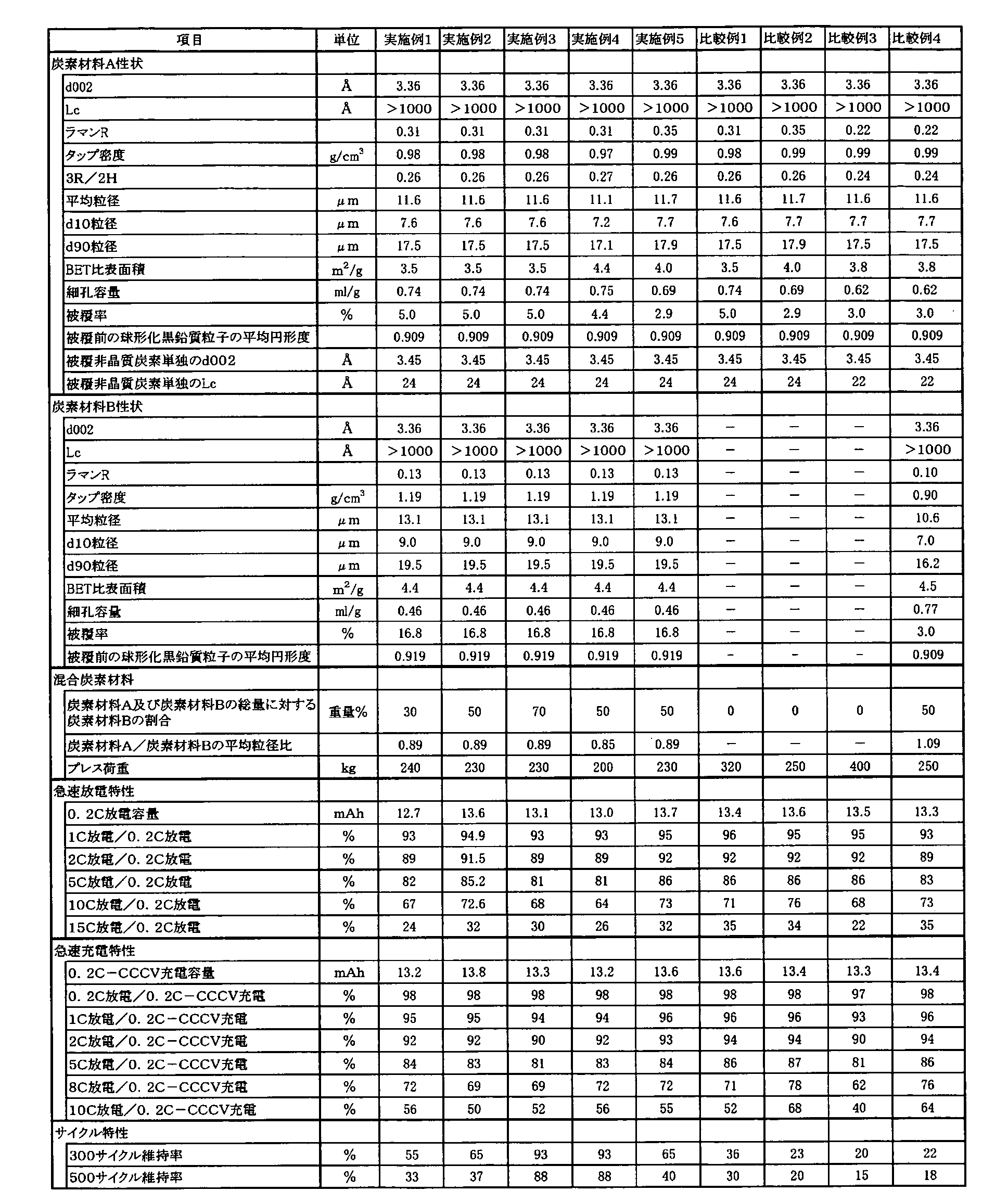
なお本出願は、2009年3月27日付で出願された日本特許出願(特願2009-079950)に基づいており、その全体が引用により援用される。 Although the invention has been described in detail using specific embodiments, it will be apparent to those skilled in the art that various modifications and variations can be made without departing from the spirit and scope of the invention.
This application is based on a Japanese patent application (Japanese Patent Application No. 2009-079950) filed on March 27, 2009, which is incorporated by reference in its entirety.
Claims (13)
- 以下の炭素材料Aおよび炭素材料Bを含む非水電解液二次電池用負極材料。
(炭素材料A)黒鉛質粒子及びその表面を被覆する非晶質炭素を含む複層構造炭素材料であり、X線広角回折法による002面の面間隔(d002)が3.37Å以下、Lcが900Å以上、タップ密度が0.8g/cm3以上、アルゴンイオンレーザーラマンスペクトルにおける1580cm-1付近のピーク強度に対する1360cm-1付近のピーク強度比であるラマンR値が0.25~0.6である炭素材料。
(炭素材料B)X線広角回折法による002面の面間隔(d002)が3.37Å以下、Lcが900Å以上、タップ密度が0.8g/cm3以上、アルゴンイオンレーザーラマンスペクトルにおける1580cm-1付近のピーク強度に対する1360cm-1付近のピーク強度比であるラマンR値が0.11~0.2である炭素材料。 A negative electrode material for a non-aqueous electrolyte secondary battery comprising the following carbon material A and carbon material B.
(Carbon material A) is a multi-layer structure carbon material containing graphite particles and amorphous carbon covering the surface thereof, and has a 002 plane spacing (d002) of 3.37 mm or less and Lc of X-ray wide angle diffraction method. 900Å or more, the tap density is 0.8 g / cm 3 or more, in the Raman R value is from 0.25 to 0.6 which is the peak intensity ratio in the vicinity of 1360 cm -1 to the peak intensity near 1580 cm -1 in the argon ion laser Raman spectrum A carbon material.
(Carbon material B) 002 plane spacing (d002) by X-ray wide angle diffraction method is 3.37 mm or less, Lc is 900 mm or more, tap density is 0.8 g / cm 3 or more, and 1580 cm −1 in an argon ion laser Raman spectrum. A carbon material having a Raman R value of 0.11 to 0.2, which is a peak intensity ratio in the vicinity of 1360 cm −1 to a peak intensity in the vicinity. - 炭素材料Aと炭素材料Bの平均粒径の比(炭素材料Aの平均粒径/炭素材料Bの平均粒径)が0.7~1.3の範囲内にある請求項1に記載の非水電解液二次電池用負極材料。 The ratio of the average particle diameter of the carbon material A and the carbon material B (average particle diameter of the carbon material A / average particle diameter of the carbon material B) is in the range of 0.7 to 1.3. Negative electrode material for water electrolyte secondary battery.
- 炭素材料A及び炭素材料Bの総量に対する炭素材料Bの割合が30~70重量%である請求項1又は2に記載の非水電解液二次電池用負極材料。 3. The negative electrode material for a non-aqueous electrolyte secondary battery according to claim 1, wherein the ratio of the carbon material B to the total amount of the carbon material A and the carbon material B is 30 to 70% by weight.
- 炭素材料(A)に用いる黒鉛質粒子のX線広角回折法による002面の面間隔(d002)が3.37Å以下、Lcが900Å以上、タップ密度が0.8g/cm3以上、アルゴンイオンレーザーラマンスペクトルにおける1580cm-1付近のピーク強度に対する1360cm-1付近のピーク強度比であるラマンR値が0.2~0.5である請求項1~3のいずれか1項に記載の非水電解液二次電池用負極材料。 Graphite particles used for the carbon material (A) have an 002 plane spacing (d002) of 3.37 mm or less, an Lc of 900 mm or more, a tap density of 0.8 g / cm 3 or more, and an argon ion laser. nonaqueous according to any one of claims 1 to 3 Raman R value is the peak intensity ratio in the vicinity of 1360 cm -1 to the peak intensity near 1580 cm -1 is 0.2-0.5 in the Raman spectrum Negative electrode material for liquid secondary batteries.
- 炭素材料(B)が球形化黒鉛質粒子とその表面を被覆する黒鉛質炭素を含む複層構造炭素材料である請求項1~4のいずれか1項に記載の非水電解液二次電池用負極材料。 The non-aqueous electrolyte secondary battery according to any one of claims 1 to 4, wherein the carbon material (B) is a multi-layer structure carbon material containing spherical graphite particles and graphitic carbon covering the surface thereof. Negative electrode material.
- 球形化黒鉛質粒子のX線広角回折法による002面の面間隔(d002)が3.37Å以下、Lcが900Å以上、タップ密度が0.8g/cm3以上、アルゴンイオンレーザーラマンスペクトルにおける1580cm-1付近のピーク強度に対する1360cm-1付近のピーク強度比であるラマンR値が0.2~0.5の範囲にある請求項5に記載の非水電解液二次電池用負極材料。 The 002 plane spacing (d002) of spheroidized graphite particles is 3.37 mm or less, Lc is 900 mm or more, tap density is 0.8 g / cm 3 or more, and 1580 cm − in an argon ion laser Raman spectrum. anode material for non-aqueous electrolyte secondary battery of claim 5 the Raman R value is the peak intensity ratio in the vicinity of 1360 cm -1 is in the range of 0.2-0.5 to the peak intensity near 1.
- 炭素材料Aの比表面積が0.5~8m2/gである請求項1~6のいずれか1項に記載の非水電解液二次電池用負極材料。 The negative electrode material for a non-aqueous electrolyte secondary battery according to any one of claims 1 to 6, wherein the specific surface area of the carbon material A is 0.5 to 8 m 2 / g.
- 炭素材料Aに用いる黒鉛質粒子の、フロー式粒子解析計で求められる平均円形度が0.88以上である請求項1~7のいずれか1項に記載の非水電解液二次電池用負極材料。 The negative electrode for a non-aqueous electrolyte secondary battery according to any one of claims 1 to 7, wherein the graphite particles used in the carbon material A have an average circularity determined by a flow particle analyzer of 0.88 or more. material.
- 炭素材料Bに用いる球形化黒鉛質粒子の、フロー式粒子解析計で求められる平均円形度が0.88以上である請求項1~8のいずれか1項に記載の非水電解液二次電池用負極材料。 The nonaqueous electrolyte secondary battery according to any one of claims 1 to 8, wherein the spheroidized graphite particles used for the carbon material B have an average circularity determined by a flow type particle analyzer of 0.88 or more. Negative electrode material.
- 炭素材料A及び炭素材料Bの水銀圧入法による10nm~100000nmの範囲の細孔容量が、0.4ml/g以上である請求項1~9のいずれか1項に記載の非水電解液二次電池用負極材料。 The non-aqueous electrolyte secondary solution according to any one of claims 1 to 9, wherein the pore volume of carbon material A and carbon material B in the range of 10 nm to 100000 nm by mercury porosimetry is 0.4 ml / g or more. Negative electrode material for batteries.
- 炭素材料Aの平均粒径が2~30μmの範囲にある請求項1~10のいずれか1項に記載の非水電解液二次電池用負極材料。 11. The negative electrode material for a non-aqueous electrolyte secondary battery according to claim 1, wherein the average particle diameter of the carbon material A is in the range of 2 to 30 μm.
- 請求項1~11のいずれか1項に記載の非水電解液二次電池用負極材料及び結着樹脂を含有する負極層、並びに集電体を含む非水電解液二次電池用負極。 A negative electrode for a non-aqueous electrolyte secondary battery comprising the negative electrode layer for a non-aqueous electrolyte secondary battery according to any one of claims 1 to 11 and a binder layer containing a binder resin, and a current collector.
- 請求項12に記載の負極、リチウムイオンを吸蔵放出できる正極及び非水電解液を備える非水電解液二次電池。 A non-aqueous electrolyte secondary battery comprising the negative electrode according to claim 12, a positive electrode capable of occluding and releasing lithium ions, and a non-aqueous electrolyte.
Priority Applications (3)
| Application Number | Priority Date | Filing Date | Title |
|---|---|---|---|
| EP10756239.9A EP2413404B1 (en) | 2009-03-27 | 2010-03-26 | Negative electrode material for nonaqueous electrolyte secondary battery and nonaqueous electrolyte secondary battery using the same |
| CN201080013295.6A CN102362380B (en) | 2009-03-27 | 2010-03-26 | Negative electrode material for non-aqueous electrolyte secondary battery and non-aqueous electrolyte secondary battery using same |
| US13/242,608 US8974969B2 (en) | 2009-03-27 | 2011-09-23 | Negative electrode material for nonaqueous electrolyte secondary battery, and nonaqueous electrolyte secondary battery using the same |
Applications Claiming Priority (2)
| Application Number | Priority Date | Filing Date | Title |
|---|---|---|---|
| JP2009-079950 | 2009-03-27 | ||
| JP2009079950 | 2009-03-27 |
Related Child Applications (1)
| Application Number | Title | Priority Date | Filing Date |
|---|---|---|---|
| US13/242,608 Continuation US8974969B2 (en) | 2009-03-27 | 2011-09-23 | Negative electrode material for nonaqueous electrolyte secondary battery, and nonaqueous electrolyte secondary battery using the same |
Publications (1)
| Publication Number | Publication Date |
|---|---|
| WO2010110443A1 true WO2010110443A1 (en) | 2010-09-30 |
Family
ID=42781133
Family Applications (1)
| Application Number | Title | Priority Date | Filing Date |
|---|---|---|---|
| PCT/JP2010/055423 WO2010110443A1 (en) | 2009-03-27 | 2010-03-26 | Negative electrode material for non-aqueous electrolyte secondary battery and non-aqueous electrolyte secondary battery using same |
Country Status (6)
| Country | Link |
|---|---|
| US (1) | US8974969B2 (en) |
| EP (1) | EP2413404B1 (en) |
| JP (1) | JP5589489B2 (en) |
| KR (1) | KR101641749B1 (en) |
| CN (1) | CN102362380B (en) |
| WO (1) | WO2010110443A1 (en) |
Cited By (3)
| Publication number | Priority date | Publication date | Assignee | Title |
|---|---|---|---|---|
| WO2013146144A1 (en) * | 2012-03-30 | 2013-10-03 | 日本電気株式会社 | Negative electrode material for secondary cell, and secondary cell |
| JP2017050184A (en) * | 2015-09-02 | 2017-03-09 | 三菱化学株式会社 | Carbon material for nonaqueous secondary battery, and lithium ion secondary battery |
| WO2022264384A1 (en) * | 2021-06-17 | 2022-12-22 | 昭和電工マテリアルズ株式会社 | Negative electrode material for lithium ion secondary batteries, negative electrode for lithium ion secondary batteries, and lithium ion secondary battery |
Families Citing this family (29)
| Publication number | Priority date | Publication date | Assignee | Title |
|---|---|---|---|---|
| JP5799710B2 (en) | 2010-09-29 | 2015-10-28 | 三菱化学株式会社 | Non-aqueous electrolyte secondary battery negative electrode carbon material and manufacturing method thereof, non-aqueous secondary battery negative electrode and non-aqueous electrolyte secondary battery using the same |
| WO2013098962A1 (en) * | 2011-12-27 | 2013-07-04 | 株式会社日立製作所 | Nonaqueous secondary battery |
| US9537176B2 (en) | 2012-09-06 | 2017-01-03 | Kureha Corporation | Material for non-aqueous electrolyte secondary battery negative electrode |
| JP2014067625A (en) * | 2012-09-26 | 2014-04-17 | Sanyo Electric Co Ltd | Nonaqueous electrolytic secondary battery |
| JP6097706B2 (en) * | 2013-01-29 | 2017-03-15 | Jfeケミカル株式会社 | Carbonaceous coated graphite particles, production method thereof, negative electrode for lithium ion secondary battery and lithium ion secondary battery |
| KR101864904B1 (en) * | 2013-05-09 | 2018-06-05 | 주식회사 엘지화학 | Methode for measuring electrode density and porosity |
| EP3076461B1 (en) | 2013-11-27 | 2018-06-27 | Mitsubishi Chemical Corporation | Carbon material for negative electrode of nonaqueous rechargeable battery, negative electrode for nonaqueous rechargeable battery, and nonaqueous rechargeable battery |
| JP2015130324A (en) * | 2013-12-05 | 2015-07-16 | 株式会社リコー | Nonaqueous electrolyte secondary battery |
| EP3131143B1 (en) | 2014-03-25 | 2019-03-20 | Hitachi Chemical Company, Ltd. | Negative electrode material for lithium-ion secondary battery, method for manufacturing negative electrode material for lithium-ion secondary battery, negative electrode material slurry for lithium-ion secondary battery, negative electrode for lithium-ion secondary battery, and lithium-ion secondary battery |
| JP6318758B2 (en) * | 2014-03-25 | 2018-05-09 | 三菱ケミカル株式会社 | Non-aqueous secondary battery carbon material and non-aqueous secondary battery |
| CN106463727B (en) * | 2014-03-31 | 2019-03-15 | Nec 能源元器件株式会社 | Negative electrode active material, negative electrode and lithium ion secondary battery based on graphite |
| EP3168908B1 (en) * | 2014-07-07 | 2019-01-23 | Hitachi Metals, Ltd. | Lithium ion secondary battery positive electrode material, lithium ion secondary battery positive electrode and lithium ion secondary battery that use same, and method for manufacturing lithium ion secondary battery positive electrode material |
| WO2016008951A1 (en) * | 2014-07-15 | 2016-01-21 | Imerys Graphite & Carbon Switzerland Ltd. | Hydrophilic surface-modified carbonaceous particulate material |
| JP6240586B2 (en) * | 2014-10-28 | 2017-11-29 | Jfeケミカル株式会社 | Graphite particles for negative electrode material of lithium ion secondary battery, negative electrode of lithium ion secondary battery and lithium ion secondary battery |
| JP6672755B2 (en) * | 2014-12-08 | 2020-03-25 | 三菱ケミカル株式会社 | Carbon materials and non-aqueous secondary batteries |
| EP3273511B1 (en) | 2015-03-19 | 2019-12-25 | Envision AESC Energy Devices Ltd. | Negative electrode for non-aqueous electrolyte secondary cell, and non-aqueous electrolyte secondary cell in which said negative electrode is used |
| US20190237763A1 (en) * | 2016-06-23 | 2019-08-01 | Showa Denko K.K. | Graphite material and secondary battery electrode using same |
| CN110249459B (en) | 2017-01-31 | 2022-11-18 | 株式会社村田制作所 | Negative electrode for secondary battery, battery pack, electric vehicle, power storage system, electric power tool, and electronic device |
| JP6183569B1 (en) * | 2017-02-24 | 2017-08-23 | Tdk株式会社 | Negative electrode active material, negative electrode and lithium ion secondary battery |
| JP6183570B1 (en) * | 2017-02-24 | 2017-08-23 | Tdk株式会社 | Negative electrode active material, negative electrode and lithium ion secondary battery |
| JP6206611B1 (en) * | 2017-03-03 | 2017-10-04 | Tdk株式会社 | Negative electrode and lithium ion secondary battery |
| WO2018207333A1 (en) * | 2017-05-11 | 2018-11-15 | 日立化成株式会社 | Lithium ion secondary battery negative electrode material, lithium ion secondary battery negative electrode material production method, lithium ion secondary battery negative electrode, and lithium ion secondary battery |
| KR102425002B1 (en) * | 2017-11-06 | 2022-07-22 | 삼성에스디아이 주식회사 | Negative active material for rechargeable lithium battery, and rechargeable lithium battery including same |
| KR20200135340A (en) * | 2018-03-29 | 2020-12-02 | 미쯔비시 케미컬 주식회사 | Negative electrode material for non-aqueous secondary battery, negative electrode for non-aqueous secondary battery and non-aqueous secondary battery |
| CN109950474B (en) | 2018-06-29 | 2020-04-24 | 宁德时代新能源科技股份有限公司 | Lithium ion battery |
| WO2020105196A1 (en) * | 2018-11-22 | 2020-05-28 | 日立化成株式会社 | Negative electrode material for lithium-ion secondary cell, method for manufacturing negative electrode material for lithium-ion secondary cell, negative electrode material slurry for lithium-ion secondary cell, negative electrode for lithium-ion secondary cell, and lithium-ion secondary cell |
| EP4060763A4 (en) * | 2019-11-11 | 2024-02-07 | Resonac Corp | Composite material, manufacturing method therefor, negative electrode material for lithium ion secondary battery, and the like |
| JP7349346B2 (en) * | 2019-12-23 | 2023-09-22 | パナソニックホールディングス株式会社 | Negative electrode for non-aqueous electrolyte secondary batteries and non-aqueous electrolyte secondary batteries |
| JP7271598B2 (en) * | 2021-04-15 | 2023-05-11 | プライムプラネットエナジー&ソリューションズ株式会社 | Negative electrode for non-aqueous electrolyte secondary battery and non-aqueous electrolyte secondary battery |
Citations (15)
| Publication number | Priority date | Publication date | Assignee | Title |
|---|---|---|---|---|
| JPH05307977A (en) * | 1992-04-28 | 1993-11-19 | Mitsubishi Petrochem Co Ltd | Nonaqueous solvent secondary battery and electrode material thereof |
| JPH1145715A (en) * | 1997-05-30 | 1999-02-16 | Matsushita Electric Ind Co Ltd | Manufacture of nonaqueous electrolytic secondary battery and of its negative electrode |
| JPH1154123A (en) * | 1997-05-30 | 1999-02-26 | Matsushita Electric Ind Co Ltd | Nonaqueous electrolyte secondary battery |
| JP2004079344A (en) * | 2002-08-19 | 2004-03-11 | Tokai Carbon Co Ltd | Negative electrode material for non-aqueous electrolyte secondary battery |
| JP2004127913A (en) * | 2002-07-31 | 2004-04-22 | Matsushita Electric Ind Co Ltd | Lithium secondary battery |
| JP3534391B2 (en) | 1998-11-27 | 2004-06-07 | 三菱化学株式会社 | Carbon material for electrode and non-aqueous secondary battery using the same |
| JP2004253379A (en) * | 2003-01-29 | 2004-09-09 | Jfe Chemical Corp | Negative electrode material and negative electrode for lithium-ion secondary battery, and lithium-ion secondary battery |
| JP2004335302A (en) * | 2003-05-08 | 2004-11-25 | Nissan Motor Co Ltd | Polymer battery, and manufacturing method of electrode for polymer battery |
| JP2005071679A (en) * | 2003-08-21 | 2005-03-17 | Sony Corp | Battery |
| JP2005158718A (en) * | 2003-10-31 | 2005-06-16 | Showa Denko Kk | Carbon material for battery electrode, and manufacturing method and use thereof |
| JP2005294011A (en) | 2004-03-31 | 2005-10-20 | Sanyo Electric Co Ltd | Nonaqueous electrolyte secondary battery |
| JP2007169160A (en) * | 2007-02-08 | 2007-07-05 | Mitsubishi Chemicals Corp | Carbon powder having high packing property for electrode plate of nonaqueous electrolyte secondary battery |
| JP2007180025A (en) * | 2005-12-02 | 2007-07-12 | Mitsubishi Chemicals Corp | Lithium ion secondary battery |
| JP2007191389A (en) * | 2007-01-29 | 2007-08-02 | Mitsubishi Chemicals Corp | Carbon or graphite particle |
| JP2008305661A (en) * | 2007-06-07 | 2008-12-18 | Tokai Carbon Co Ltd | Negative electrode material for lithium ion secondary battery, and its manufacturing method |
Family Cites Families (9)
| Publication number | Priority date | Publication date | Assignee | Title |
|---|---|---|---|---|
| JPH03291756A (en) | 1990-04-10 | 1991-12-20 | Toshiba Corp | Picture formation storage device |
| WO1998054779A1 (en) | 1997-05-30 | 1998-12-03 | Matsushita Electric Industrial Co., Ltd. | Nonaqueous electrolyte secondary battery |
| KR100530910B1 (en) | 1997-05-30 | 2005-11-23 | 마츠시타 덴끼 산교 가부시키가이샤 | Nonaqueous electrolyte secondary battery and method for manufacturing negative electrode of the same |
| US6632569B1 (en) * | 1998-11-27 | 2003-10-14 | Mitsubishi Chemical Corporation | Carbonaceous material for electrode and non-aqueous solvent secondary battery using this material |
| US7052803B2 (en) | 2002-07-31 | 2006-05-30 | Matsushita Electric Industrial Co., Ltd. | Lithium rechargeable battery |
| JP2005044775A (en) * | 2003-01-22 | 2005-02-17 | Hitachi Maxell Ltd | Negative electrode for lithium secondary battery, manufacturing method of the same, and lithium secondary battery using the same |
| KR101930127B1 (en) | 2005-10-20 | 2018-12-17 | 미쯔비시 케미컬 주식회사 | Lithium secondary cell and nonaqueous electrolytic solution for use therein |
| JP3953502B1 (en) * | 2006-05-08 | 2007-08-08 | 真幸 芳尾 | Power storage system |
| JP5268018B2 (en) * | 2006-12-26 | 2013-08-21 | 三菱化学株式会社 | Non-aqueous secondary battery composite graphite particles, negative electrode material containing the same, negative electrode and non-aqueous secondary battery |
-
2010
- 2010-03-26 KR KR1020117022165A patent/KR101641749B1/en active IP Right Grant
- 2010-03-26 WO PCT/JP2010/055423 patent/WO2010110443A1/en active Application Filing
- 2010-03-26 CN CN201080013295.6A patent/CN102362380B/en active Active
- 2010-03-26 JP JP2010073163A patent/JP5589489B2/en active Active
- 2010-03-26 EP EP10756239.9A patent/EP2413404B1/en active Active
-
2011
- 2011-09-23 US US13/242,608 patent/US8974969B2/en active Active
Patent Citations (16)
| Publication number | Priority date | Publication date | Assignee | Title |
|---|---|---|---|---|
| JPH05307977A (en) * | 1992-04-28 | 1993-11-19 | Mitsubishi Petrochem Co Ltd | Nonaqueous solvent secondary battery and electrode material thereof |
| JP3291756B2 (en) | 1992-04-28 | 2002-06-10 | 三菱化学株式会社 | Non-aqueous solvent secondary battery and its electrode material |
| JPH1145715A (en) * | 1997-05-30 | 1999-02-16 | Matsushita Electric Ind Co Ltd | Manufacture of nonaqueous electrolytic secondary battery and of its negative electrode |
| JPH1154123A (en) * | 1997-05-30 | 1999-02-26 | Matsushita Electric Ind Co Ltd | Nonaqueous electrolyte secondary battery |
| JP3534391B2 (en) | 1998-11-27 | 2004-06-07 | 三菱化学株式会社 | Carbon material for electrode and non-aqueous secondary battery using the same |
| JP2004127913A (en) * | 2002-07-31 | 2004-04-22 | Matsushita Electric Ind Co Ltd | Lithium secondary battery |
| JP2004079344A (en) * | 2002-08-19 | 2004-03-11 | Tokai Carbon Co Ltd | Negative electrode material for non-aqueous electrolyte secondary battery |
| JP2004253379A (en) * | 2003-01-29 | 2004-09-09 | Jfe Chemical Corp | Negative electrode material and negative electrode for lithium-ion secondary battery, and lithium-ion secondary battery |
| JP2004335302A (en) * | 2003-05-08 | 2004-11-25 | Nissan Motor Co Ltd | Polymer battery, and manufacturing method of electrode for polymer battery |
| JP2005071679A (en) * | 2003-08-21 | 2005-03-17 | Sony Corp | Battery |
| JP2005158718A (en) * | 2003-10-31 | 2005-06-16 | Showa Denko Kk | Carbon material for battery electrode, and manufacturing method and use thereof |
| JP2005294011A (en) | 2004-03-31 | 2005-10-20 | Sanyo Electric Co Ltd | Nonaqueous electrolyte secondary battery |
| JP2007180025A (en) * | 2005-12-02 | 2007-07-12 | Mitsubishi Chemicals Corp | Lithium ion secondary battery |
| JP2007191389A (en) * | 2007-01-29 | 2007-08-02 | Mitsubishi Chemicals Corp | Carbon or graphite particle |
| JP2007169160A (en) * | 2007-02-08 | 2007-07-05 | Mitsubishi Chemicals Corp | Carbon powder having high packing property for electrode plate of nonaqueous electrolyte secondary battery |
| JP2008305661A (en) * | 2007-06-07 | 2008-12-18 | Tokai Carbon Co Ltd | Negative electrode material for lithium ion secondary battery, and its manufacturing method |
Non-Patent Citations (1)
| Title |
|---|
| See also references of EP2413404A4 |
Cited By (5)
| Publication number | Priority date | Publication date | Assignee | Title |
|---|---|---|---|---|
| WO2013146144A1 (en) * | 2012-03-30 | 2013-10-03 | 日本電気株式会社 | Negative electrode material for secondary cell, and secondary cell |
| JPWO2013146144A1 (en) * | 2012-03-30 | 2015-12-10 | 日本電気株式会社 | Anode material for secondary battery and secondary battery |
| US9748556B2 (en) | 2012-03-30 | 2017-08-29 | Nec Corporation | Negative electrode material for secondary battery, and secondary battery |
| JP2017050184A (en) * | 2015-09-02 | 2017-03-09 | 三菱化学株式会社 | Carbon material for nonaqueous secondary battery, and lithium ion secondary battery |
| WO2022264384A1 (en) * | 2021-06-17 | 2022-12-22 | 昭和電工マテリアルズ株式会社 | Negative electrode material for lithium ion secondary batteries, negative electrode for lithium ion secondary batteries, and lithium ion secondary battery |
Also Published As
| Publication number | Publication date |
|---|---|
| CN102362380A (en) | 2012-02-22 |
| EP2413404B1 (en) | 2016-12-14 |
| CN102362380B (en) | 2015-05-13 |
| JP2010251314A (en) | 2010-11-04 |
| JP5589489B2 (en) | 2014-09-17 |
| EP2413404A1 (en) | 2012-02-01 |
| EP2413404A4 (en) | 2015-08-26 |
| US8974969B2 (en) | 2015-03-10 |
| KR20120003442A (en) | 2012-01-10 |
| US20120064403A1 (en) | 2012-03-15 |
| KR101641749B1 (en) | 2016-07-21 |
Similar Documents
| Publication | Publication Date | Title |
|---|---|---|
| JP5943052B2 (en) | Negative electrode material for non-aqueous electrolyte secondary battery and non-aqueous electrolyte secondary battery using the same | |
| JP5589489B2 (en) | Negative electrode material for non-aqueous electrolyte secondary battery and non-aqueous electrolyte secondary battery using the same | |
| KR101952464B1 (en) | Carbon material and negative electrode for nonaqueous secondary battery and nonaqueous secondary battery | |
| JP5974573B2 (en) | Negative electrode material for non-aqueous secondary battery, negative electrode for non-aqueous secondary battery, and non-aqueous secondary battery | |
| WO2012133611A1 (en) | Negative electrode material for nonaqueous secondary battery, negative electrode using the same, and nonaqueous secondary battery | |
| JP6268729B2 (en) | Negative electrode material for non-aqueous secondary battery, negative electrode for non-aqueous secondary battery, and non-aqueous secondary battery | |
| JP6060506B2 (en) | Negative electrode material for non-aqueous secondary battery, negative electrode for non-aqueous secondary battery, and non-aqueous secondary battery | |
| KR20130113439A (en) | Carbon material for negative electrode of nonaqueous electrolyte secondary battery, method for producing same, negative electrode of nonaqueous secondary battery using same, and nonaqueous electrolyte secondary battery | |
| JP7102868B2 (en) | Artificial graphite-based negative electrode material, negative electrode for non-aqueous secondary batteries and non-aqueous secondary batteries | |
| JP2021061230A (en) | Negative electrode material for nonaqueous secondary battery, negative electrode for nonaqueous secondary battery, and nonaqueous secondary battery | |
| JP2014067680A (en) | Graphite particle for nonaqueous secondary battery, negative electrode for nonaqueous secondary battery using the same, and nonaqueous secondary battery | |
| JP5724199B2 (en) | Anode material for non-aqueous electrolyte secondary battery, method for producing the same, and non-aqueous electrolyte secondary battery | |
| JP7248019B2 (en) | Negative electrode material for non-aqueous secondary battery, negative electrode for non-aqueous secondary battery, and non-aqueous secondary battery | |
| JP2021158044A (en) | Negative electrode material raw material for nonaqueous secondary battery, negative electrode material for nonaqueous secondary battery, negative electrode for nonaqueous secondary battery, and nonaqueous secondary battery | |
| JP7388109B2 (en) | Negative electrode materials for non-aqueous secondary batteries, negative electrodes for non-aqueous secondary batteries, and non-aqueous secondary batteries | |
| JP7452140B2 (en) | Graphite-based negative electrode materials for non-aqueous secondary batteries, negative electrodes for non-aqueous secondary batteries, and non-aqueous secondary batteries | |
| JP7099005B2 (en) | Negative electrode material for non-aqueous secondary batteries and its manufacturing method, negative electrode for non-aqueous secondary batteries and non-aqueous secondary batteries | |
| JP7009049B2 (en) | Lithium-ion secondary battery Carbon material for negative electrode, its intermediate, its manufacturing method, and negative electrode or battery using it |
Legal Events
| Date | Code | Title | Description |
|---|---|---|---|
| WWE | Wipo information: entry into national phase |
Ref document number: 201080013295.6 Country of ref document: CN |
|
| 121 | Ep: the epo has been informed by wipo that ep was designated in this application |
Ref document number: 10756239 Country of ref document: EP Kind code of ref document: A1 |
|
| ENP | Entry into the national phase |
Ref document number: 20117022165 Country of ref document: KR Kind code of ref document: A |
|
| REEP | Request for entry into the european phase |
Ref document number: 2010756239 Country of ref document: EP |
|
| WWE | Wipo information: entry into national phase |
Ref document number: 2010756239 Country of ref document: EP |
|
| NENP | Non-entry into the national phase |
Ref country code: DE |