WO2010110364A1 - 絞り装置 - Google Patents
絞り装置 Download PDFInfo
- Publication number
- WO2010110364A1 WO2010110364A1 PCT/JP2010/055206 JP2010055206W WO2010110364A1 WO 2010110364 A1 WO2010110364 A1 WO 2010110364A1 JP 2010055206 W JP2010055206 W JP 2010055206W WO 2010110364 A1 WO2010110364 A1 WO 2010110364A1
- Authority
- WO
- WIPO (PCT)
- Prior art keywords
- sides
- pair
- diaphragm
- aperture
- diaphragm blade
- Prior art date
- Legal status (The legal status is an assumption and is not a legal conclusion. Google has not performed a legal analysis and makes no representation as to the accuracy of the status listed.)
- Ceased
Links
Images



Classifications
-
- G—PHYSICS
- G03—PHOTOGRAPHY; CINEMATOGRAPHY; ANALOGOUS TECHNIQUES USING WAVES OTHER THAN OPTICAL WAVES; ELECTROGRAPHY; HOLOGRAPHY
- G03B—APPARATUS OR ARRANGEMENTS FOR TAKING PHOTOGRAPHS OR FOR PROJECTING OR VIEWING THEM; APPARATUS OR ARRANGEMENTS EMPLOYING ANALOGOUS TECHNIQUES USING WAVES OTHER THAN OPTICAL WAVES; ACCESSORIES THEREFOR
- G03B9/00—Exposure-making shutters; Diaphragms
- G03B9/02—Diaphragms
Definitions
- the present invention relates to an aperture device, and more particularly, to an aperture device that is mounted on a video camera and has excellent bokeh and ghost shape.
- the opening shape formed by the diaphragm blades is usually a rhombus or a square.
- the closer the aperture shape formed by the aperture blades is to a circle the more beautiful the soft focus and the blur in portrait, and the better the quality.
- the ghost shape generated under backlight is similar to the opening shape, the closer the opening shape is to a circle, the better the quality of the ghost shape. Therefore, it is always desired to make the opening shape formed by the aperture blades as close to a circle as possible so as to improve the quality of the bokeh and ghost shape.
- an aperture device mounted on a lens used in a high-performance still camera such as a single-lens reflex camera arranges 6 or 8 aperture blades in the circumferential direction around the optical axis, and each aperture blade Many of them have a structure that drives them so as to be separated from and in contact with the optical axis in a plane orthogonal to the optical axis.
- the opening shapes formed by the diaphragm blades are hexagonal or octagonal, respectively, the quality of the bokeh and ghost shape can be improved.
- the apparatus becomes larger in the radial direction. It is difficult to adopt for video cameras.
- two of the four diaphragm blades are arranged opposite to each other with respect to the optical axis, and are driven in a direction in which they are separated from each other on one axis passing through the optical axis.
- Japanese Patent Application Laid-Open No. 2004-228688 discloses a diaphragm device that obtains the opening shape of the above.
- the diaphragm device described in Patent Document 1 Since the diaphragm device described in Patent Document 1 has a structure in which the diaphragm blades are driven so as to be separated from each other on one axis passing through the optical axis, it can be thinned in a direction perpendicular to the one axis.
- the aperture shape formed by the aperture blades is a hexagon, the quality of the bokeh and ghost shape is better than in the case of a rhombus or a square.
- the apex angle is an acute angle in the shape of the diaphragm blade, the stroke for closing the opposed diaphragm blade is long, and the device is downsized. There is room for improvement.
- An object of the present invention is to provide an aperture device that can further improve the quality of the bokeh and ghost shape.
- Another object of the present invention is to provide a diaphragm device that can further improve the quality of the bokeh and ghost shape and can be further miniaturized.
- the aperture device of the present invention has the following configurations (1) to (5).
- a rotation arm that rotates clockwise / counterclockwise around a predetermined rotation axis, and is connected to the rotation arm, and has a V-shaped apex angle that is far from the rotation axis.
- a first diaphragm blade having a first pair of sides formed so as to be closer to each other, and connected to the rotating arm, the apex angle is an obtuse V shape, and the closer to the rotating shaft, the closer to each other.
- a second diaphragm blade having a second pair of sides formed as described above and a pivot arm connected to the pivot arm and formed so as to approach each other as the apex angle is an acute V-shape and is farther from the pivot shaft.
- a third pair of diaphragm blades having a third pair of sides and a fourth pair connected to the rotating arm and formed so as to approach each other as the apex angle is an acute V-shape and closer to the rotating shaft.
- a fourth diaphragm blade having the sides of the first to fourth portions as the rotary arm rotates.
- Throttle apparatus characterized by the area of the open window formed by being surrounded by the pair of sides changes.
- the third diaphragm blade has a connecting side that connects the third pair of sides so that the third pair of sides does not intersect at the apex.
- the fourth diaphragm blade has a connecting side that connects the fourth pair of sides so that the fourth pair of sides does not intersect at the apex.
- the aperture device of the present invention it is possible to further improve the quality of the bokeh and ghost shape. Further, according to the aperture device of the present invention, it is possible to further improve the quality of the bokeh and ghost shape, and to further reduce the size.
- FIG. 6 is a plan view for explaining first to fourth diaphragm blades of the diaphragm device according to the embodiment of the present invention. It is a top view for demonstrating the effect of the aperture_diaphragm
- a throttling device according to an embodiment of the present invention will be described in detail with reference to FIGS.
- FIG. 1 is an external perspective view of a diaphragm device according to an embodiment of the present invention.
- the base plate 6 is a plate-like member formed with the axis CLn direction as the longitudinal direction.
- the base plate 6 has a circular opening 6k centered on the intersection of the axis CLt and the axis CLt orthogonal to the axis CLn.
- the aperture device 50 is disposed on the optical path of the imaging device so that the center of the opening 6k coincides with the optical axis of the imaging device such as a video camera.
- the base plate 6 has two pairs of guide pins 6a and 6b and guide pins 6c and 6d that are provided so as to project symmetrically with respect to the axis CLn along the axis CLn.
- a rotating arm 5 is provided on the lower side of the base plate 6 in FIG.
- the rotation arm 5 is connected to the galvanometer 7 and is driven to rotate in the direction of the arrow RT1 within a predetermined angle range about the rotation axis CL1 by the galvanometer 7.
- the rotation by the galvanometer 7 is controlled from the imaging device side so that the imaging device on which the aperture device 50 is mounted has an aperture value for capturing a good image.
- the rotating arm 5 is provided with four projecting drive pins. Specifically, drive pins 5b and 5a are provided from the rotation axis CL1 side on the left side of FIG. 1 with respect to the rotation axis CL1, and the rotation axis CL1 side is provided on the right side of FIG. Drive pins 5c and 5d are provided.
- the base plate 6 is provided with four diaphragm blades engaged with the guide pins 6a to 6d and the drive pins 5a to 5d, respectively. Specifically, the four diaphragm blades are arranged in order from the side farther from the base plate 6 (the front side in FIG. 1), the first diaphragm blade 1, the second diaphragm blade 2, the third diaphragm blade 3, and the third diaphragm blade. 4 aperture blades 4.
- the first to fourth diaphragm blades 1 to 4 are light shielding means for moving light back and forth inside the opening 6k, shielding light passing through the opening 6k, and controlling the amount of light passing therethrough.
- the first to fourth aperture blades 1 to 4 are provided with slits that are long in the direction of the axis CLn and engage with the guide pins 6a to 6d. Accordingly, the first to fourth aperture blades 1 to 4 are guided by the guide pins 6a to 6d, respectively, and are movable in the direction of the axis CLn.
- the first to fourth aperture blades 1 to 4 are engaged with the drive pins 5a to 5d as follows.
- the first aperture blade 1 is engaged only with the drive pin 5b.
- the second aperture blade 2 is engaged only with the drive pin 5c.
- the third aperture blade 3 is engaged only with the drive pin 5a.
- the fourth diaphragm blade 4 is engaged only with the drive pin 5d. Accordingly, the first to fourth aperture blades 1 to 4 are positioned at predetermined positions in the direction of the axis CLn according to the rotation angle of the rotation arm 5 as the rotation arm 5 rotates.
- 2A and 2B show the rotating arm 5 and the first and second aperture blades 1 and 2, respectively.
- FIGS. 2C and 2D show the rotating arm 5 and the third and fourth aperture blades 3 and 4.
- the first aperture blade 1 is a member surrounded by a thick solid line in FIG.
- the first diaphragm blade 1 has a pair of sides 1a and 1b that are symmetrical with respect to the axis CLn and form an apex angle ⁇ 1 at the edge.
- the apex angle ⁇ 1 is an obtuse angle and is 135 degrees in the present embodiment.
- the vertex P1 is on the side far from the rotation axis CL1 with respect to the sides 1a and 1b.
- the first aperture blade 1 is engaged with the drive pin 5b in the lower part of FIG.
- the second diaphragm blade 2 is a member surrounded by a thick solid line and a thick dotted line in FIG.
- the second diaphragm blade 2 has a pair of sides 2a and 2b that are symmetrical with respect to the axis line CLn and form an apex angle ⁇ 2.
- the apex angle ⁇ 2 is an obtuse angle and is 135 degrees in the present embodiment.
- the vertex P2 is on the side close to the rotation axis CL1 with respect to the sides 2a and 2b.
- the second aperture blade 2 is engaged with the drive pin 5c in the lower part of FIG.
- the third aperture blade 3 is a member surrounded by a thick solid line in FIG.
- the third diaphragm blade 3 has a pair of sides 3a and 3b which are symmetrical with respect to the axis line CLn and form an apex angle ⁇ 3 at the edge.
- the apex angle ⁇ 3 is an acute angle and is 45 degrees in the present embodiment.
- the vertex P3 is on the side far from the rotation axis CL1 with respect to the sides 3a and 3b.
- the third aperture blade 3 has a side 3c that is orthogonal to the axis CLn and connects the ends of the sides 3a and 3b on the side far from the rotation axis CL1.
- the third aperture blade 3 is engaged with the drive pin 5a in the lower part of FIG.
- the fourth diaphragm blade 4 is a member surrounded by a thick solid line and a thick dotted line in FIG.
- the fourth diaphragm blade 4 has a pair of sides 4a and 4b that are symmetrical with respect to the axis CLn and form an apex angle ⁇ 4 at the edge.
- the apex angle ⁇ 4 is an acute angle and is 45 degrees in the present embodiment.
- the vertex P4 is on the side closer to the rotation axis CL1 than the sides 4a and 4b.
- the fourth aperture blade 4 has a side 4c that is orthogonal to the axis CLt and connects ends of the sides 4a and 4b closer to the rotation axis CL1.
- the fourth blade 4 is engaged with the drive pin 5d in the lower part of FIG.
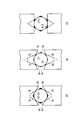
- FIG. 3A shows a regular octagonal opening window K1 inscribed in the opening window K1.
- the region between the opening window K1 and the circle C1 is painted black. The smaller the area of the black coating, the closer the aperture shape of the diaphragm is to a circle, and the quality of the bokeh and ghost shape can be further improved.
- FIG. 3A shows a circle C1 inscribed in the opening window K1.
- the region between the opening window K1 and the circle C1 is painted black. The smaller the area of the black coating, the closer the aperture shape of the diaphragm is to a circle, and the quality of the bokeh and ghost shape can be further improved.
- FIG. 3A shows a comparative example.
- FIG. 3C shows a regular hexagonal opening window K10 and a circle C10 inscribed therein in a conventional diaphragm device. Similarly, the region between the opening window K10 and the circle C10 is painted black. Comparing the black areas of FIG. 3 (a) and FIG. 3 (c), it is clear that the opening window K1 of the present embodiment is closer to the circular opening. Therefore, it can be seen that the aperture device according to the present embodiment can improve the quality of the blur and the ghost shape.
- the size of the opening window K1 can be arbitrarily changed according to the rotation angle of the rotation lever 5.
- the sides 1 a and 1 b of the first diaphragm blade 1 and the sides 2 a and 2 b of the second diaphragm blade 2 are separated from each other by the rotation of the rotation lever 5.
- the sides 3 a and 3 b of the third diaphragm blade 3 and the sides 4 a and 4 b of the fourth diaphragm blade 4 are brought into contact with each other by the rotation of the rotation lever 5.
- the sides 1a, 1b, 2a, 2b, 3a, 3b, 4a, 4b By performing the separation of the sides 1a, 1b and the sides 2a, 2b and the separation of the sides 3a, 3b and the sides 4a, 4b at the same time, the sides 1a, 1b, 2a, 2b, 3a, 3b, 4a, 4b.
- the size of the enclosed opening window 1k changes.
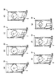
- FIG. 4A (a) shows a state in which the rotation lever 5 is at the maximum clockwise position within the allowable rotation range.
- FIG. 4B (n) shows a state in which the rotation lever 5 is at the maximum counterclockwise position.
- FIGS. 4A (b) to 4 (g) and FIGS. 4B (h) to (m) are rotations in which the rotation allowable range of the rotation lever 5 is substantially equally divided from the maximum clockwise position to the maximum counterclockwise position. The position and state of the lever 5 are shown respectively. That is, in FIG. 4A (a), the aperture window K1 has a minimum aperture (open end), and in FIG. 4B (n), the aperture window K1 has a maximum aperture (minimum aperture).
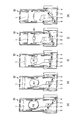
- FIGS. 4A (a), (d), (f), and FIG. 4B (j) are perspective views corresponding to FIGS. 4A (a), (d), (f), and FIG. 4B (j), respectively.
- FIG. 5 (n) shows a state where the stroke is further expanded from the state of FIG. 4B (n) to completely close the opening window K1.
- the opening window K2 is composed of eight sides of the sides 1a, 1b, 2a, 2b, 3a, 3b, 4a, and 4b, and has an octagonal shape with inner angles of 120 degrees and 150 degrees. .
- FIG. 3B shows the opening window K2 and a circle C2 inscribed therein.
- region between the opening window K2 and the circle C2 is painted black. Comparing the black areas of FIG. 3A and FIG. 3B, the opening window K2 of the modification of the present embodiment is blacker than the regular octagonal opening window K1 (see FIG. 3A). Although the paint area is large, the black paint area is smaller than that of the conventional opening window K10 (see FIG. 3C). It can be seen that the quality of the shape can be improved.
- the distances from the rotation axis CL1 of the rotation lever 5 to the drive pins 5b, 5a, 5c, 5d are Lb, La, Lc, Ld, respectively.
- the shape of the opening window K2 is independent of the rotational position of the rotating lever 5. It will be similar.
- the third diaphragm blade 3 is provided with a side 3c
- the fourth diaphragm blade 4 is provided with a side 4c. That is, the side 3a and the side 3b of the third diaphragm blade 3 are connected so as not to intersect at the vertex P3 via the side 3c, and the side 4a and the side 4b of the fourth diaphragm blade 4 define the side 4c. Are connected so as not to intersect at the vertex P4.
- the fourth diaphragm blade 4 has a side with respect to a stroke which is a movement distance in the direction of the axis CLn necessary to completely close the opening window K1 when there is no side 4c.
- the stroke in the direction of the axis CLn necessary to completely close the opening window K1 is shortened by ⁇ St4.
- the diaphragm device 50 shortens the outer dimension in the direction of the axis CLn by the length indicated by ⁇ St3 + ⁇ St4. It is possible to reduce the size.
- the sides 3c and 4c function as stroke shortening means.
- the sides 3c and 4c do not contribute to the formation of the opening window K1.
- the sides 3c and 4c constitute the sides of the opening window K1, and thus the octagon is not maintained.
- the position where the stroke shortening means is provided is preferably within a range where the aperture window K1 shape on the small aperture side does not practically affect the image quality.
- the configuration of the first to fourth diaphragm blades is as follows.
- the first diaphragm blade is connected to the rotating arm, and has a first pair of sides formed so as to approach each other as the distance from the rotating shaft increases.
- the second diaphragm blade is connected to the rotating arm, and has a second pair of sides formed such that the apex angle is an obtuse V shape and the closer to the rotating shaft, the closer to each other.
- the third diaphragm blade is connected to the rotating arm, and has a third pair of sides formed so as to approach each other as the apex angle becomes an acute V-shape and the distance from the rotating shaft increases.
- the fourth diaphragm blade is connected to the rotation arm, and has a fourth pair of sides formed so that the apex angle is an acute V-shape and the closer to the rotation axis, the closer to each other.
- the ends of the sides 3a and 3b far from the rotation axis CL1 are connected by arcs and / or the sides 4a and 4b on the side closer to the rotation axis CL1. You may connect an edge part.
- the apex angles ⁇ 1 to ⁇ 4 of the first to fourth aperture blades 1 to 4 are not limited to the angles described above. Although a regular octagon cannot be obtained by increasing the apex angles ⁇ 3 and ⁇ 4 of the third and fourth aperture blades 3 and 4, the stroke can be shortened, so priority is given to circular approximation of the aperture window, or the axis CLn A numerical value may be determined based on whether or not priority is given to miniaturization by shortening the stroke in the direction. Regardless of the value of the apex angles ⁇ 1 to ⁇ 4, the ratio of the distances Lb, La, Lc, and Ld can be set so that the size of the aperture window is changed in a similar manner.
- the stroke shortening means is provided without restricting the shape of the opening window to an octagon, the moving distance of the diaphragm blades is shortened and the diaphragm device can be miniaturized.
Landscapes
- Physics & Mathematics (AREA)
- General Physics & Mathematics (AREA)
- Diaphragms For Cameras (AREA)
Abstract
絞り装置は、回動アーム及び第1~4の絞り羽根を備える。回動アームは、所定の回動軸の回りに回動する。第1の絞り羽根は、回動アームに連結され、頂角が鈍角のV字状で回動軸より遠いほど互いに接近するよう形成された第1の一対の辺を有する。第2の絞り羽根は、回動アームに連結され、頂角が鈍角のV字状で回動軸に近いほど互いに接近するよう形成された第2の一対の辺を有する。第3の絞り羽根は、回動アームに連結され、頂角が鋭角のV字状で回動軸より遠いほど互いに接近するよう形成された第3の一対の辺を有する。第4の絞り羽根は、回動アームに連結され、頂角が鋭角のV字状で回動軸に近いほど互いに接近するよう形成された第4の一対の辺を有する。回動アームの回動に伴い、第1~4の一対の辺に囲まれて形成された開口窓の面積が変化する。
Description
本発明は、絞り装置に係り、特に、ビデオカメラに搭載されボケ味やゴースト形状の品位が良好な絞り装置に関する。
従来、ビデオカメラの絞り装置は、絞り羽根が2枚で構成されるものが多い。絞り羽根が2枚の場合、絞り羽根により形成される開口形状は、通常、菱形または正方形とされる。一般に、絞り羽根で形成される開口形状が円に近い程、ソフトフォーカスやポートレートでのボケ味は美しく、品位が良好となる。また、逆光下で生じるゴースト形状は、開口形状と相似になるため、開口形状が円に近い程、ゴースト形状の品位は良好になる。従って、絞り羽根で形成される開口形状をできるだけ円に近づけて、ボケ味やゴースト形状の品位をより良好にすることが、常に望まれている。
これに応えて、一眼レフ等の高性能なスチルカメラに用いられるレンズに搭載される絞り装置は、光軸を中心として周方向に6枚、あるいは8枚の絞り羽根を配接し、各絞り羽根を光軸に直交する面内で光軸に対して離接するように駆動する構造を有するものが多い。この構造によれば、絞り羽根により形成される開口形状がそれぞれ六角形、あるいは八角形になるので、ボケ味やゴースト形状の品位を良化することができる。
しかしながら、絞り羽根を光軸に対して周方向に配設して径方向に離接させる構造を採用すると、装置は径方向へ大型化するので、小型化や薄型化が要求されるスチルカメラやビデオカメラへの採用は難しい。
そこで、4枚の絞り羽根のうち2枚の絞り羽根を1組にした2組を光軸に対して互いに対向配置し、光軸を通る一軸上で互いに離接する方向に駆動して、六角形の開口形状を得る絞り装置が特許文献1に開示されている。
特許文献1に記載された絞り装置は、絞り羽根を、光軸を通る一軸上で互いに離接させるよう駆動する構造であるため、その一軸に直交する方向の薄型化が可能である。また、絞り羽根により形成される開口形状が六角形であるから、菱形や正方形の場合と比べてボケ味やゴースト形状の品位は良好となる。一方、特許文献1に記載された絞り装置は、絞り羽根の形状において、頂角が鋭角とされているために、対向する絞り羽根を閉じきるためのストロークが長くなっており、装置の小型化については改善の余地がある。さらに、近年、高精細画像が一般に普及するに伴い、ビデオカメラに対しては、小型化、薄型化に加え、画質の品位向上についても要求が高くなっている。そのため、絞り装置に対しては、更なる小型化とボケ味やゴースト形状の更なる品位向上とが望まれている。
本発明の目的は、ボケ味やゴースト形状の更なる品位向上が可能な絞り装置を提供することにある。本発明の別の目的は、ボケ味やゴースト形状の更なる品位向上が可能で、かつ、更なる小型化も可能な絞り装置を提供することにある。
上記の課題を解決するために、本発明の絞り装置は次の(1)~(5)の構成を有する。
(1)所定の回動軸のまわりに時計回り/反時計回り方向に回動する回動アームと、前記回動アームに連結され、頂角が鈍角のV字状で前記回動軸より遠いほど互いに接近するよう形成された第1の一対の辺を有する第1の絞り羽根と、前記回動アームに連結され、頂角が鈍角のV字状で前記回動軸に近いほど互いに接近するよう形成された第2の一対の辺を有する第2の絞り羽根と、前記回動アームに連結され、頂角が鋭角のV字状で前記回動軸より遠いほど互いに接近するよう形成された第3の一対の辺を有する第3の絞り羽根と、前記回動アームに連結され、頂角が鋭角のV字状で前記回動軸に近いほど互いに接近するよう形成された第4の一対の辺を有する第4の絞り羽根と、を備え、前記回動アームの回動に伴い、前記第1~4の一対の辺に囲まれて形成された開口窓の面積が変化することを特徴とする絞り装置。
(2)前記回動アームの回動に伴い、前記第1の一対の辺と前記第2の一対の辺とが互いに離接し、かつ、前記第3の一対の辺と前記第4の一対の辺とが互いに離接することを特徴とする(1)に記載の絞り装置。
(3)前記開口窓が正八角形であることを特徴とする(1)または(2)に記載の絞り装置。
(4)前記第3の絞り羽根は、前記第3の一対の辺が頂点で交わらないように、前記第3の一対の辺を連結する連結辺を有することを特徴とする(1)~(3)のいずれかに記載の絞り装置。
(5)前記第4の絞り羽根は、前記第4の一対の辺が頂点で交わらないように、前記第4の一対の辺を連結する連結辺を有することを特徴とする(1)~(3)のいずれかに記載の絞り装置。
本発明の絞り装置によれば、ボケ味やゴースト形状の更なる品位向上が可能になる。また、本発明の絞り装置によれば、ボケ味やゴースト形状の更なる品位向上が可能で、かつ更なる小型化も可能になる。
本発明の実施の形態に係る絞り装置を図1~図5を用いて詳細に説明する。
図1は、本発明の実施の形態に係る絞り装置の外観斜視図である。
図1において、ベース板6は軸線CLn方向を長手方向として形成された板状部材である。ベース板6は、軸線CLnと直交する軸線CLtとの交点を中心とする円形の開口部6kを有している。絞り装置50は、開口部6kの中心をビデオカメラなどの撮像装置の光軸に一致するように、撮像装置の光路上に配置される。ベース板6は、軸線CLnに沿って、軸線CLnに対して対称な位置に突設された2対の案内ピン6a,6bと案内ピン6c,6dを有している。ベース板6の図1における下方側には、回動アーム5が回動軸CL1のまわりの時計回り及び反時計回り(矢印RT1方向)に回動可能に設けられている。回動アーム5は、ガルバノメータ7と連結されており、ガルバノメータ7により回動軸CL1を中心として所定の角度範囲で矢印RT1方向に回動駆動される。ガルバノメータ7による回動は、絞り装置50が搭載された撮像装置が良好な画像を撮像する絞り値となるように、撮像装置側から制御される。
回動アーム5には、突出する4つの駆動ピンが設けられている。具体的には、回動軸CL1に対して図1の左方側に、回動軸CL1側から駆動ピン5b,5aが設けられており、図1の右方側に、回動軸CL1側から駆動ピン5c,5dが設けられている。
ベース板6には、案内ピン6a~6dと駆動ピン5a~5dとにそれぞれ係合した4枚の絞り羽根が備えられている。具体的には、4枚の絞り羽根は、ベース板6から遠い側(図1の手前側)から順に、第1の絞り羽根1,第2の絞り羽根2,第3の絞り羽根3,第4の絞り羽根4である。第1~4の絞り羽根1~4は、開口部6kの内部に進退して、開口部6kを通過する光を遮光し、通過する光量を制御する遮光手段である。
第1~4の絞り羽根1~4には、軸線CLn方向に長く開口して、案内ピン6a~6dと係合するスリットがそれぞれ設けられている。従って、第1~4の絞り羽根1~4は、案内ピン6a~6dにそれぞれ案内されて、軸線CLn方向に移動可能とされている。
第1~4の絞り羽根1~4は駆動ピン5a~5dと以下のようにそれぞれ係合している。第1の絞り羽根1は駆動ピン5bのみと係合している。第2の絞り羽根2は駆動ピン5cのみと係合している。第3の絞り羽根3は駆動ピン5aのみと係合している。第4の絞り羽根4は駆動ピン5dとのみ係合している。従って、第1~4の絞り羽根1~4は、回動アーム5の回動に伴い、回動アーム5の回動角度に応じた軸線CLn方向の所定の場所に位置する。
次に、図2(a)~(d)を用いて第1~4の絞り羽根1~4の形状を説明する。図2(a),(b)は、回動アーム5と第1,第2の絞り羽根1,2を示している。図2(c),(d)は、回動アーム5と第3,第4の絞り羽根3,4を示している。
第1の絞り羽根1は、図2(a)において太い実線で囲った部材である。第1の絞り羽根1は、縁部に、軸線CLnに対して対称であって頂角θ1をなす一対の辺1a,1bを有している。頂角θ1は鈍角とされ、本実施の形態においては135度である。頂点P1は辺1a,1bに対して回動軸CL1から遠い側にある。第1の絞り羽根1は、図2(a)の下方において駆動ピン5bと係合している。
第2の絞り羽根2は、図2(b)において太い実線及び太い点線で囲った部材である。第2の絞り羽根2は、縁部に、軸線CLnについて対称であって頂角θ2をなす一対の辺2a,2bを有している。頂角θ2は鈍角とされ、本実施の形態においては135度である。頂点P2は辺2a,2bに対して回動軸CL1に近い側にある。第2の絞り羽根2は、図2(b)の下方において駆動ピン5cと係合している。
第3の絞り羽根3は、図2(c)において太い実線で囲った部材である。第3の絞り羽根3は、縁部に、軸線CLnについて対称であって頂角θ3をなす一対の辺3a,3bを有している。頂角θ3は鋭角とされ、本実施の形態においては45度である。頂点P3は辺3a,3bに対して回動軸CL1から遠い側にある。第3の絞り羽根3は、軸線CLnに直交して辺3a,3bの回動軸CL1から遠い側の端部を連結する辺3cを有している。第3の絞り羽根3は、図2(c)の下方において駆動ピン5aと係合している。
第4の絞り羽根4は、図2(d)において太い実線及び太い点線で囲った部材である。第4の絞り羽根4は、縁部に、軸線CLnについて対称であって頂角θ4をなす一対の辺4a,4bを有している。頂角θ4は鋭角とされ、本実施の形態においては45度である。頂点P4は辺4a,4bに対して回動軸CL1から近い側にある。第4の絞り羽根4は、軸線CLtに直交して辺4a,4bの回動軸CL1から近い側の端部を連結する辺4cを有している。第4の羽根4は、図2(d)の下方において駆動ピン5dと係合している。
上述した構成において、第1~4の絞り羽根1~4を組み合わせると、図3(a)に示すように、辺1a,1b,2a,2b,3a,3b,4a,4bの8つの辺からなる正八角形の開口窓K1が得られる。図3(a)は、その開口窓K1に内接する円C1も示している。開口窓K1と円C1との間の領域には黒色を塗っている。この黒塗りの面積が小さい程、絞りの開口形状が円に近いことになり、ボケ味やゴースト形状の品位をより良化できる。図3(c)に比較例として、従来の絞り装置における正六角形の開口窓K10と、それに内接する円C10とを示している。同様に、開口窓K10と円C10との間の領域には黒色を塗っている。図3(a)と図3(c)との黒塗りの面積を比較すると、本実施の形態の開口窓K1の方が円形開口により近いことが明らかである。従って、本実施の形態の絞り装置により良好にボケ味やゴースト形状の品位を向上できることがわかる。
開口窓K1の大きさは、回動レバー5の回動角度により任意に変えることができる。第1の絞り羽根1における辺1a,1bと第2の絞り羽根2における辺2a,2bとは、回動レバー5の回動により互いに離接する。第3の絞り羽根3における辺3a,3bと第4の絞り羽根4における辺4a,4bとは、回動レバー5の回動により、互いに離接する。辺1a,1bと辺2a,2bの離接と辺3a,3bと辺4a,4bの離接が同時に実行されることにより、辺1a,1b,2a,2b,3a,3b,4a,4bで囲まれた開口窓1kの大きさが変化する。
図4A(a)は、回動レバー5が回動許容範囲の最大右回り位置にある状態を示している。図4B(n)は、回動レバー5が最大左回り位置にある状態を示している。図4A(b)~(g)及び図4B(h)~(m)は、回動レバー5の回動許容範囲の最大右回り位置から最大左回り位置までの間を概ね等分割した回動レバー5の位置及び状態をそれぞれ示している。すなわち、図4A(a)で開口窓K1は最小絞り(開放端)となり、図4B(n)で開口窓K1は最大絞り(最小開口)となっている。
図5(a),(d),(f),(j)は、それぞれ図4A(a),(d),(f),図4B(j)にそれぞれ対応する斜視図である。図5(n)は、図4B(n)の状態からさらにストロークを拡張して開口窓K1を閉じきった状態を示している。
ここで、回動レバー5の回動軸CL1から駆動ピン5b,5a,5c,5dまでの距離をそれぞれLb,La,Lc,Ldとしたときに、互いの比率を、Lb:La:Lc:Ld=1:2.41:-2.41:-1と設定すると、開口窓K1の形状は、回動レバー5の回転位置に拘わらず相似となる。
第1~4の絞り羽根1~4の頂角θ1~θ4は次のように設定してもよい:θ1=θ2=120度,θ3=θ4=60度。この条件の場合に、開口窓K2は、辺1a,1b,2a,2b,3a,3b,4a,4bの8つの辺からなり、内角が120度と150度とで構成された八角形となる。
図3(b)は、開口窓K2とそれに内接する円C2とを示している。図3(b)において、開口窓K2と円C2との間の領域を黒色を塗っている。図3(a)と図3(b)との黒塗りの面積を比較すると、本実施の形態の変形例の開口窓K2は、正八角形の開口窓K1(図3(a)参照)より黒塗りの面積が大きいものの、従来の開口窓K10(図3(c)参照〕より黒塗りの面積は小さくなっている。従って、本実施の形態の変形例の絞り装置により良好にボケ味やゴースト形状の品位を向上できることがわかる。
θ1=θ2=120度,θ3=θ4=60度とした場合、回動レバー5の回動軸CL1から駆動ピン5b,5a,5c,5dまでの距離をそれぞれLb,La,Lc,Ldとしたときに、互いの比率を、Lb:La:Lc:Ld=1:1.73:-1.73:-1と設定すると、開口窓K2の形状は、回動レバー5の回転位置に拘わらず相似となる。
本実施の形態において、第3の絞り羽根3に辺3cを設け、第4の絞り羽根4に辺4cを設けている。すなわち、第3の絞り羽根3の辺3aと辺3bとは、辺3cを介して頂点P3で交わらないように連結され、第4の絞り羽根4の辺4aと辺4bとは、辺4cを介して頂点P4で交わらないように連結されている。
これにより、第3の絞り羽根3について、図2(c)に示すように、辺3cがない場合に開口窓K1を閉じきるために必要な軸線CLn方向の移動距離であるストロークSt1に対し、辺3cを設けた場合に開口窓K1を閉じきるために必要な軸線CLn方向のストロークSt2はΔSt3だけ短くなっている。同様に、第4の絞り羽根4について、図2(d)に示すように、辺4cがない場合に開口窓K1を閉じきるために必要な軸線CLn方向の移動距離であるストロークに対し、辺4cを設けた場合に開口窓K1を閉じきるために必要な軸線CLn方向のストロークはΔSt4だけ短くなっている。
従って、第3の絞り羽根3及び第4の絞り羽根4に辺3c及び辺4cをそれぞれ設けたことにより、絞り装置50は、軸線CLn方向の外形寸法を、ΔSt3+ΔSt4で示される長さだけ短くすることができ、小型化が可能となっている。
このように、辺3c,辺4cは、ストローク短縮手段として機能する。開口窓K1が有る程度面積が確保されている段階(例えば、図4A(a)~図4B(l)で示される段階)では、辺3c,辺4cは、開口窓K1の形成に寄与しない。これに対して、開口窓K1の面積が極小になる図4B(m),(n)の状態では、辺3c,辺4cが開口窓K1の辺を構成するので、八角形が維持されない。従って、ストローク短縮手段を設ける位置は、小絞り側の、開口窓K1形状が実用上画質に影響を及ぼさない範囲内であることが好ましい。
第1~4の絞り羽根の構成は以下のとおりである。第1の絞り羽根は、回動アームに連結されており、頂角が鈍角のV字状で回動軸より遠いほど互いに接近するよう形成された第1の一対の辺を有している。第2の絞り羽根は、回動アームに連結されており、頂角が鈍角のV字状で回動軸に近いほど互いに接近するよう形成された第2の一対の辺を有している。第3の絞り羽根は、回動アームに連結されており、頂角が鋭角のV字状で回動軸より遠いほど互いに接近するよう形成された第3の一対の辺を有している。第4の絞り羽根は、回動アームに連結されており、頂角が鋭角のV字状で回動軸に近いほど互いに接近するよう形成された第4の一対の辺を有している。
本発明の実施例は、上述した構成及び手順に限定されるものではなく、本発明の要旨を逸脱しない範囲において変形例としてもよい。
辺3c,4cを設ける代わりに、円弧で辺3aと辺3bとの回動軸CL1から遠い側の端部を連結し、及び/又は辺4aと辺4bとの回動軸CL1から近い側の端部を連結してもよい。
第1~4の絞り羽根1~4の頂角θ1~θ4は、上述した角度に限定されない。第3,4の絞り羽根3,4の頂角θ3,θ4を大きくすることで正八角形は得られないものの、ストロークを短縮することができるので、開口窓の円近似を優先するか、軸線CLn方向のストローク短縮による小型化を優先するかに基づいて数値を決定すればよい。頂角θ1~θ4がいずれの値をとっても、距離Lb,La,Lc,Ldの比率を開口窓の大きさを相似形で変化させるように設定することができる。
開口窓の形状を八角形に制限せずにストローク短縮手段を設ければ、絞り羽根の移動距離が短くなって絞り装置を小型化できる。
1~4 第1~4の絞り羽根
1a,2a,3a,4a 辺
1b,2b,3b,4b 辺
1c,2c 辺(ストローク短縮手段)
5 回動アーム
5a~5d 駆動ピン
6 ベース板
6a~6d 案内ピン
6k 開口部
7 ガルバノメータ
50 絞り装置
CL1 回動軸
CLn,CLt 軸線
K1 開口窓
P1~P4 頂点
θ1~θ4 頂角
1a,2a,3a,4a 辺
1b,2b,3b,4b 辺
1c,2c 辺(ストローク短縮手段)
5 回動アーム
5a~5d 駆動ピン
6 ベース板
6a~6d 案内ピン
6k 開口部
7 ガルバノメータ
50 絞り装置
CL1 回動軸
CLn,CLt 軸線
K1 開口窓
P1~P4 頂点
θ1~θ4 頂角
Claims (5)
- 所定の回動軸まわりに時計回り/反時計回り方向に回動する回動アームと、
前記回動アームに連結され、頂角が鈍角のV字状で前記回動軸より遠いほど互いに接近するよう形成された第1の一対の辺を有する第1の絞り羽根と、
前記回動アームに連結され、頂角が鈍角のV字状で前記回動軸に近いほど互いに接近するよう形成された第2の一対の辺を有する第2の絞り羽根と、
前記回動アームに連結され、頂角が鋭角のV字状で前記回動軸より遠いほど互いに接近するよう形成された第3の一対の辺を有する第3の絞り羽根と、
前記回動アームに連結され、頂角が鋭角のV字状で前記回動軸に近いほど互いに接近するよう形成された第4の一対の辺を有する第4の絞り羽根と、
を備え、
前記回動アームの回動に伴い、前記第1~4の一対の辺に囲まれて形成された開口窓の面積が変化することを特徴とする絞り装置。 - 前記回動アームの回動に伴い、前記第1の一対の辺と前記第2の一対の辺とが互いに離接し、かつ、前記第3の一対の辺と前記第4の一対の辺とが互いに離接することを特徴とする請求項1記載の絞り装置。
- 前記開口窓が正八角形であることを特徴とする請求項1または請求項2記載の絞り装置。
- 前記第3の絞り羽根は、前記第3の一対の辺が頂点で交わらないように、前記第3の一対の辺を連結する連結辺を有することを特徴とする請求項1~3のいずれか1項に記載の絞り装置。
- 前記第4の絞り羽根は、前記第4の一対の辺が頂点で交わらないように、前記第4の一対の辺を連結する連結辺を有することを特徴とする請求項1~3のいずれか1項に記載の絞り装置。
Applications Claiming Priority (2)
| Application Number | Priority Date | Filing Date | Title |
|---|---|---|---|
| JP2009078536A JP2010230980A (ja) | 2009-03-27 | 2009-03-27 | 絞り装置 |
| JP2009-078536 | 2009-03-27 |
Publications (1)
| Publication Number | Publication Date |
|---|---|
| WO2010110364A1 true WO2010110364A1 (ja) | 2010-09-30 |
Family
ID=42781058
Family Applications (1)
| Application Number | Title | Priority Date | Filing Date |
|---|---|---|---|
| PCT/JP2010/055206 Ceased WO2010110364A1 (ja) | 2009-03-27 | 2010-03-25 | 絞り装置 |
Country Status (2)
| Country | Link |
|---|---|
| JP (1) | JP2010230980A (ja) |
| WO (1) | WO2010110364A1 (ja) |
Citations (5)
| Publication number | Priority date | Publication date | Assignee | Title |
|---|---|---|---|---|
| JPH05241224A (ja) * | 1992-02-26 | 1993-09-21 | Minolta Camera Co Ltd | 絞り装置 |
| JPH1062835A (ja) * | 1996-08-19 | 1998-03-06 | Sony Corp | 光量絞り装置 |
| JP2002162665A (ja) * | 2000-11-27 | 2002-06-07 | Canon Inc | 光量調節装置 |
| JP2006178366A (ja) * | 2004-12-24 | 2006-07-06 | Nidec Copal Corp | カメラ用羽根駆動装置 |
| JP2009031664A (ja) * | 2007-07-30 | 2009-02-12 | Nidec Copal Corp | 光学機器用羽根駆動装置 |
-
2009
- 2009-03-27 JP JP2009078536A patent/JP2010230980A/ja active Pending
-
2010
- 2010-03-25 WO PCT/JP2010/055206 patent/WO2010110364A1/ja not_active Ceased
Patent Citations (5)
| Publication number | Priority date | Publication date | Assignee | Title |
|---|---|---|---|---|
| JPH05241224A (ja) * | 1992-02-26 | 1993-09-21 | Minolta Camera Co Ltd | 絞り装置 |
| JPH1062835A (ja) * | 1996-08-19 | 1998-03-06 | Sony Corp | 光量絞り装置 |
| JP2002162665A (ja) * | 2000-11-27 | 2002-06-07 | Canon Inc | 光量調節装置 |
| JP2006178366A (ja) * | 2004-12-24 | 2006-07-06 | Nidec Copal Corp | カメラ用羽根駆動装置 |
| JP2009031664A (ja) * | 2007-07-30 | 2009-02-12 | Nidec Copal Corp | 光学機器用羽根駆動装置 |
Also Published As
| Publication number | Publication date |
|---|---|
| JP2010230980A (ja) | 2010-10-14 |
Similar Documents
| Publication | Publication Date | Title |
|---|---|---|
| CN103080830B (zh) | 光量调节装置和光学设备 | |
| US20150160438A1 (en) | Imaging apparatus having bending optical element | |
| US4797700A (en) | Diaphragm device | |
| CN120491270A (zh) | 光路转换模块及包括其的相机模块和便携式终端 | |
| US9004786B2 (en) | Light quantity adjusting device and imaging apparatus | |
| JP6624786B2 (ja) | 絞り装置及びそれを有するレンズ装置及び撮像装置 | |
| JP6810443B2 (ja) | 絞り装置、レンズ鏡筒及び撮像装置又は投影装置 | |
| WO2018105401A1 (ja) | 絞り装置、レンズ鏡筒及び撮像装置又は投影装置 | |
| TW202321737A (zh) | 相機模組 | |
| JP2003005248A (ja) | 虹彩型光量調節装置、レンズ鏡筒および撮影装置 | |
| US7307803B2 (en) | Zoom lens device | |
| JP2006184775A (ja) | 反射型光学系およびこれを用いた投写型表示装置 | |
| JP2021021802A (ja) | 絞り装置及びそれを有するレンズ装置及び撮像装置 | |
| US4974001A (en) | Diaphragm device | |
| WO2010110364A1 (ja) | 絞り装置 | |
| US20240152035A1 (en) | Optical system | |
| JP5355073B2 (ja) | レンズバリア装置 | |
| US10754118B2 (en) | Lens barrel and imaging device equipped with same | |
| JP3605175B2 (ja) | 光量制御装置 | |
| JP5897887B2 (ja) | レンズ鏡筒 | |
| JPH10301159A (ja) | 絞り装置 | |
| JP2015132723A (ja) | 投射光学系および画像表示装置 | |
| WO2020039759A1 (ja) | 撮像装置、及び撮像システム | |
| JP2007140250A (ja) | 撮影レンズの絞り装置 | |
| KR20150006291A (ko) | 조리개 조립체 |
Legal Events
| Date | Code | Title | Description |
|---|---|---|---|
| 121 | Ep: the epo has been informed by wipo that ep was designated in this application |
Ref document number: 10756160 Country of ref document: EP Kind code of ref document: A1 |
|
| NENP | Non-entry into the national phase |
Ref country code: DE |
|
| 122 | Ep: pct application non-entry in european phase |
Ref document number: 10756160 Country of ref document: EP Kind code of ref document: A1 |