WO2010110132A1 - ガイドワイヤーおよびガイドワイヤー挿入システム - Google Patents
ガイドワイヤーおよびガイドワイヤー挿入システム Download PDFInfo
- Publication number
- WO2010110132A1 WO2010110132A1 PCT/JP2010/054461 JP2010054461W WO2010110132A1 WO 2010110132 A1 WO2010110132 A1 WO 2010110132A1 JP 2010054461 W JP2010054461 W JP 2010054461W WO 2010110132 A1 WO2010110132 A1 WO 2010110132A1
- Authority
- WO
- WIPO (PCT)
- Prior art keywords
- guide wire
- blood vessel
- puncture
- bending portion
- main body
- Prior art date
- Legal status (The legal status is an assumption and is not a legal conclusion. Google has not performed a legal analysis and makes no representation as to the accuracy of the status listed.)
- Ceased
Links
Images





Classifications
-
- A—HUMAN NECESSITIES
- A61—MEDICAL OR VETERINARY SCIENCE; HYGIENE
- A61M—DEVICES FOR INTRODUCING MEDIA INTO, OR ONTO, THE BODY; DEVICES FOR TRANSDUCING BODY MEDIA OR FOR TAKING MEDIA FROM THE BODY; DEVICES FOR PRODUCING OR ENDING SLEEP OR STUPOR
- A61M25/00—Catheters; Hollow probes
- A61M25/01—Introducing, guiding, advancing, emplacing or holding catheters
- A61M25/09—Guide wires
-
- A—HUMAN NECESSITIES
- A61—MEDICAL OR VETERINARY SCIENCE; HYGIENE
- A61M—DEVICES FOR INTRODUCING MEDIA INTO, OR ONTO, THE BODY; DEVICES FOR TRANSDUCING BODY MEDIA OR FOR TAKING MEDIA FROM THE BODY; DEVICES FOR PRODUCING OR ENDING SLEEP OR STUPOR
- A61M25/00—Catheters; Hollow probes
- A61M25/01—Introducing, guiding, advancing, emplacing or holding catheters
- A61M25/09—Guide wires
- A61M25/09041—Mechanisms for insertion of guide wires
Definitions
- the present invention relates to a guide wire and a guide wire insertion system used when a catheter, in particular, a central venous catheter is placed in a blood vessel.
- the Seldinger method is a method in which a catheter is introduced and placed in a blood vessel along a guide wire introduced and placed in the blood vessel.
- the guide wire is housed in the guide wire supply device with the distal end protruding from the guide wire supply device, and enters the blood vessel through the puncture device such as a puncture needle or an indwelling needle connected to the guide wire supply device. be introduced.
- a guide wire having the following configuration As a guide wire used in such a Seldinger method, a guide wire having the following configuration has been proposed.
- the shape of the distal end portion of the guide wire protruding from the guide wire supply tool is bent at a predetermined angle (for example, 45 degrees) from the wire axis direction in the state of being housed in the guide wire supply tool.
- a guide wire having a shape (angle shape) is described.
- tip part of the guide wire which protrudes from a guide wire supply tool in the state accommodated in the guide wire supply tool curves in J shape from a wire axial direction, and the front-end
- tip Describes a guide wire having a shape open to the outside (J shape).
- a guide wire having a linear shape (straight shape) instead of a bent or curved shape is also used.
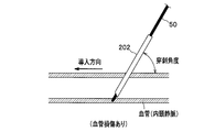
- the guide wire 50 introduced into the needle tube portion 202 (puncture needle) at the time of blood vessel puncture with a large puncture angle as described above is intended in the blood vessel. It may not be smoothly introduced in the direction of introduction and may excessively contact the inner wall of the blood vessel, resulting in blood vessel damage.
- the placement of the central venous catheter is usually placed in the thickest blood vessel in the vicinity of the heart, such as the superior vena cava and the inferior vena cava, and not placed in the thin blood vessel.
- the guide wire 50 may not be introduced from the introduction blood vessel BA into the thick blood vessel BB but may be introduced into the thin blood vessel BC at the blood vessel branching portion. This is because the shape of the distal end portion of the conventional guide wire 50 is easy to be introduced into the thin blood vessel BC from the introduction blood vessel BA, specifically, the angle shape or J shape where the distal end portion of the guide wire 50 is small. Or due to the straight shape.
- the present invention has been made in view of such a problem, and an object of the present invention is to provide a guide that does not cause puncture blood vessel damage even when the puncture angle is increased and does not introduce a thin blood vessel at a blood vessel branching portion. It is to provide a wire.
- a guide wire according to the present invention is a guide wire that is housed in a guide wire supply tool and introduced into a blood vessel via a puncture needle connected to the guide wire supply tool. And a first curved portion provided in a curved shape continuously on the distal end side of the main body portion, and a radius of curvature r1 of the first curved portion is equal to or less than a blade surface length R of the puncture needle. It is characterized by being.
- the guide wire since the guide wire has the first curved portion with the radius of curvature r smaller than the blade surface length of the puncture needle, the distal end portion of the guide wire is smoothly in the intended introduction direction in the puncture blood vessel having a large puncture angle. In this way, excessive contact with the puncture blood vessel (inner blood vessel wall) is suppressed, the size of the tip of the guide wire is increased, and introduction of the guide wire into a thin blood vessel at the blood vessel bifurcation is suppressed. Is done.
- the guide wire according to the present invention is characterized in that a radius of curvature r1 of the first curved portion is 1.8 to 3 mm. According to the above configuration, since the first curved portion has a predetermined range of curvature radius r1, the distal end portion of the guide wire is introduced more smoothly in the intended introduction direction, and contact with the puncture blood vessel (blood vessel inner wall) is further suppressed. Is done.
- the guide wire according to the present invention further includes a second bending portion that is continuously provided in a curved shape between the main body portion and the first bending portion.
- the guide wire is characterized in that the formation angle ⁇ 2 of the second bending portion is 180 to 270 degrees. Further, the guide wire is characterized in that the first bending portion is bent inward so that a tip thereof approaches the main body portion.
- the puncture is performed by further including the second bending portion, and the tip of the first bending portion being bent inward or outward, or the formation angle of the second bending portion being within a predetermined range.
- the guide wire can be further introduced, and excessive contact with the puncture vessel (inner vessel wall) is further suppressed, and the size of the tip of the guide wire is further increased, resulting in vessel branching.
- the guide wire is further suppressed from being introduced into the thin blood vessel.
- the guide wire according to the present invention is characterized in that it further has a linear portion that is provided in a straight line continuously between the first curved portion and the second curved portion.
- the guide wire is characterized in that the formation angle ⁇ 2 of the second bending portion is 180 to 270 degrees.
- the guide wire is characterized in that the first bending portion is bent outward or inward so that the tip thereof approaches the main body portion or away from the main body portion.
- the puncture has a large puncture angle by further having a straight portion and the tip of the first curved portion being curved inward or the formation angle of the second curved portion being within a predetermined range.
- the guide wire introduction property is further improved, excessive contact with the puncture blood vessel (inner blood vessel inner wall) is further suppressed, and the size of the tip of the guide wire is further increased. It is further suppressed that the wire is introduced into a thin blood vessel.
- the guide wire insertion system includes the guide wire, a puncture needle for introducing the guide wire into a blood vessel, a guide wire storage portion for storing the guide wire, and the guide wire connected to the puncture needle. And a guide wire supply device having a guide wire introducing portion for introducing the guide wire accommodated in the accommodating portion into the puncture needle.
- the guide wire since the guide wire is provided, when the guide wire is introduced into the blood vessel through the puncture needle from the guide wire supply tool, the distal end portion of the guide wire is oriented in the intended introduction direction even for a puncture blood vessel having a large puncture angle. It is smoothly introduced and excessive contact with the puncture blood vessel (inner blood vessel wall) is suppressed. Moreover, the size of the distal end portion of the guide wire is also increased at the blood vessel branching portion, and introduction of the guide wire into a thin blood vessel is suppressed.
- the puncture blood vessel is not damaged even when the puncture angle is increased, and the introduction into the thin blood vessel at the blood vessel branching portion is eliminated.
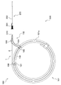
- FIG. 1 It is a side view which shows the structure of the guide wire insertion system which concerns on this invention. It is a side view which shows the structure of the guide wire of 1st Embodiment which concerns on this invention.
- (A), (b) is a schematic diagram which shows the structure of the guide wire of 2nd Embodiment which concerns on this invention.
- (A), (b) is a schematic diagram which shows the structure of the guide wire of 3rd Embodiment which concerns on this invention. It is a schematic diagram which shows the introduction state in the puncture blood vessel of the guide wire which concerns on this invention. It is a schematic diagram which shows the operation
- the guide wire 1 is a guide wire introduced into a blood vessel via a puncture needle (puncture device) 200 connected to the guide wire supply device 100.
- the guide wire supply tool 100 includes a guide wire storage unit 101 and a guide wire introduction unit 102.
- the guide wire storage unit 101 is, for example, a flexible tube (tubular body) 101a wound in a spiral shape (curved), and stores most of the guide wire 1 in the length direction therein.
- the guide wire introduction unit 102 is connected to the puncture needle (puncture device) 200 and introduces the guide wire 1 stored in the guide wire storage unit 101 into the puncture needle (puncture device) 200.
- a connection unit 103 connected to the needle (puncture tool) 200 and a delivery unit 106 that is provided at a position separated from the connection unit 103 and sends out the guide wire 1 stored in the guide wire storage unit 101 are provided. Then, the guide wire 1 delivered from the delivery unit 106 is introduced into the puncture needle (puncture device) 200 via the connection unit 103.
- the guide wire introduction unit 102 is provided at a lower portion of the delivery unit 106 and a fixing unit 105 that detachably fixes the guide wire storage unit 101 via an arm unit 104 protruding from the connection unit 103.
- the puncture device is used to puncture a predetermined part of a patient (human body) and secure a blood vessel into which the guide wire 1 is introduced, and a puncture needle or an indwelling needle is used.
- the puncture needle 200 includes a needle tube portion 202 and a hub 201 in which a lumen for fixing the needle tube portion 202 and connecting the guide wire supply tool 100 (guide wire introducing portion 102) is formed.
- the guide wire 1 of the first embodiment has a main body portion 2 and a first bending portion 3.
- a first bending portion 3 Each configuration will be described below.
- the main body 2 is linear in the natural state and has flexibility.
- the main body 2 is a part that is accommodated in the guide wire supply tool 100 in the length direction of the guide wire 1.
- the main body 2 is housed in a tube (tubular body) 101 a constituting the guide wire housing 101 while being housed in the guide wire supply tool 100.
- tip part 6 is comprised by the front-end
- FIG. As shown in FIG.
- the distal end portion 6 has a two-layer structure of a core wire 1 a and a coil 1 b. Moreover, it is preferable that the length L of the front-end
- the first bending portion 3 is a portion that is provided in a curved shape continuously to the distal end side of the main body portion 2 in the length direction of the guide wire 1.
- the distal end side of the main body portion 2 is not the side stored in the guide wire storage portion 101 but protrudes from the connection portion 103 of the guide wire introduction portion 102 and enters the blood vessel via the puncture needle (puncture device) 200.
- the side to be introduced is referred to (see FIG. 1).
- the curvature radius r1 of the first bending portion 3 is equal to or less than the blade surface length R of the puncture needle 200.
- the blade surface length R is 1.8 to 3 mm because a puncture needle 200 having an outer diameter of 18 to 22G is usually used.
- the blood vessel eg, internal jugular vein
- a large puncture angle eg, 60 to 90 degrees.
- the distal end portion 6 of the guide wire 1 has a predetermined size, and as shown in FIG.
- the wire 1 is not introduced from the introduction blood vessel BA into the thin blood vessel BC, but is introduced into the thick blood vessel BB (for example, the superior vena cava side).
- the radius of curvature r1 of the first curved portion 3 exceeds the blade surface length R, the size of the tip portion 6 of the guide wire 1 becomes too large, and the guide wire 1 is intended to be introduced in a puncture vessel having a large puncture angle.
- the blood vessel is excessively brought into contact with the blood vessel wall, causing blood vessel damage (see FIG. 8) and hindering smooth movement of the guide wire 1 in the blood vessel.
- the first bending portion 3 preferably has a formation angle ⁇ 1 of 50 to 100 degrees. In terms of the length LA, it is about 1 to 5 mm. When the formation angle ⁇ 1 is less than 50 degrees, the size of the distal end portion 6 of the guide wire 1 is small, and it is easy to be introduced into a thin blood vessel at the blood vessel branching portion. If the formation angle ⁇ 1 exceeds 100 degrees, the first bending portion 3 is likely to be entangled with the main body portion 2 (the distal end portion 2a), and smooth movement of the guide wire 1 in the blood vessel is likely to be hindered.
- the guide wires 10a and 10b of the second embodiment further include a second bending portion 4 in addition to the main body portion 2 and the first bending portion 3. That is, the 2nd bending part 4 is provided between the main-body part 2 and the 1st bending part 3 of the guide wire 1 of 1st Embodiment.
- the distal end portion 6 includes the distal end portion 2 a of the main body portion 2, the second bending portion 4, and the first bending portion 3.
- the second bending portion 4 is a portion that is continuously provided in a curved shape between the main body portion 2 (tip portion 2a) and the first bending portion 3 in the length direction of the guide wires 10a and 10b.
- the guide wires 10a and 10b can be further introduced, and excessive contact with the puncture blood vessel (inner wall of the blood vessel) is further suppressed.
- the size of the distal end portion 6 of the guide wires 10a and 10b is further increased, and the guide wires 10a and 10b are further prevented from being introduced into thin blood vessels at the blood vessel branching portion.
- the curvature radius r2 of the second bending portion 4 is preferably 2 to 5 mm, which is substantially equal to 1 ⁇ 2 of the inner diameter of the blood vessel in which the guide wire 1 is placed. This further suppresses the introduction of the guide wires 10a and 10b into the thin blood vessel at the blood vessel branching portion.
- the formation angle ⁇ 2 of the second bending portion 4 is preferably 50 to 270 degrees, and more preferably 180 to 270 degrees.
- the first bending portion 3 is likely to be entangled with the main body portion 2 (tip portion 2a), and smooth movement of the guide wire 1 in the blood vessel is likely to be hindered.
- the guide wires 11 a and 11 b of the third embodiment further include the linear portion 5 in addition to the main body portion 2, the first bending portion 3 and the second bending portion 4.
- the linear part 5 is provided between the 1st bending part 3 and the 2nd bending part 4 of the guide wires 10a and 10b of 2nd Embodiment.
- the distal end portion 6 includes a distal end portion 2 a of the main body portion 2, a second bending portion 4, a straight portion 5, and a first bending portion 3.
- the straight portion 5 is a portion that is continuously provided in a straight line between the first bending portion 3 and the second bending portion 4 in the length direction of the guide wires 11a and 11b. Since the guide wires 11a and 11b have the straight portions 5, the introduction of the guide wires 11a and 11b is further improved in a puncture blood vessel having a large puncture angle. And it is preferable that the length LB of the linear part 5 is 20 mm or less. When the length LB exceeds 20 mm, the first bending portion 3 is likely to be entangled with the main body portion 2 (tip portion 2a), and smooth movement of the guide wires 11a and 11b in the blood vessel is likely to be hindered.
- the guide wires 10a, 10b, 11a, 11b of the second embodiment and the third embodiment have the first bending portion 3 as shown in FIGS. 3 (a), 3 (b), 4 (a), 4 (b). And the second bending portion 4. And in guide wire 10a, 11a, the front-end
- tip 3a of the 1st bending part 3 takes the form curved outward so that it may distance from the main-body part 2 (front-end
- Any of the above forms may be used, but a form in which the tip 3a of the first bending portion 3 is curved inward (see the guide wires 10a and 11b, FIGS. 3A and 4A) is preferable. In this way, by bending the distal end 3a of the first bending portion 3 inward, the introduction property of the guide wire 1 in the puncture blood vessel having a large puncture angle can be further improved.
- the structure of the guide wires 1, 10 a, 10 b, 11 a, 11 b is not particularly limited, but as shown in FIG. 2, the main body 2 (excluding the tip 2 a) is made of metal (for example, Ni—Ti alloy) Single-layer structure consisting only of the core wire 1a made of the product, the tip portion 6 (the tip portion 2a and the first bending portion 3, or in addition to this, the second bending portion 4 and the straight portion 5 (FIG. 4 (a), ( The reference wire b)) is preferably a two-layer guide wire comprising a core wire 1a and a metal (for example, stainless steel) coil 1b provided on the outer periphery of the core wire 1a.
- a metal for example, stainless steel
- the guide wires 1, 10 a, 10 b, 11 a, 11 b may have a two-layer structure of the core wire 1 a and the coil 1 b as a whole in the length direction, or the whole length direction may be the core wire 1 a. It may be a guide wire having a single-layer structure made of only.
- the guide wires 1, 10a, 10b, 11a and 11b may constitute the core wire 1a and the coil 1b with synthetic resin instead of metal.
- synthetic resin elastomers such as polyolefin, polyester, polyamide, polyurethane, silicone rubber, polyvinyl chloride, fluororesin, latex rubber, and composite materials thereof can be used.
- a guide wire insertion system 300 includes a guide wire 1, a puncture needle (puncture tool) 200 for introducing the guide wire 1 into a blood vessel, a guide wire storage unit 101 for storing the guide wire 1,
- a guide wire supply device 100 having a guide wire introducing unit 102 which is connected to a puncture needle (puncture device) 200 and introduces the guide wire 1 stored in the guide wire storage unit 101 into the puncture needle (puncture device) 200; It is characterized by providing.
- the guide wire 1, the puncture needle 200, and the guide wire supply tool 100 are as described above, and thus description thereof is omitted.
- a puncture needle (puncture device) 200 is punctured while confirming an echo image at a predetermined site (for example, internal jugular vein) of a patient (human body), and the needle tube portion 202 of the puncture needle 200 is inserted into a blood vessel ( (See FIG. 5). Then, blood is sucked with a syringe or the like, and it is confirmed that the needle tube portion 202 is located in the blood vessel.
- a part of the main body 2 of the guide wire 1 stored in the guide wire storage 101 is gripped with fingers or the like, and the tip 6 (the tip 2a and part of the first bending part 3 are connected to the connection 103 (guide The connecting portion 103 is inserted into the hub 201 of the puncture needle (puncture tool) 200.
- the main body portion 2 of the guide wire 1 is grasped with fingers or the like, and the guide wire is inserted. 1 is introduced into a blood vessel via a puncture needle (puncture tool) 200.
- the puncture needle (puncture device) 200 is removed, the guide wire 1 is removed from the guide wire introducing portion 102 (connecting portion 103), and the guide wire 1 is placed in the blood vessel. Detained. Then, a central venous catheter is inserted into the blood vessel along the guide wire 1 using a dilator (not shown). Next, the guide wire 1 is removed while leaving the central venous catheter, and the central venous catheter is placed in the blood vessel. Since the guide wires 10a and 10b of the second embodiment and the guide wires 11a and 11b of the third embodiment also have the first bending portion 3, they are introduced into the blood vessel in the same manner as the guide wire 1 of the first embodiment. can do.
- Example 1 After the tip of Ni-Ti core wire (outer diameter: 0.38 mm, length: 600 mm) is tapered or machined, a stainless steel coil (outer diameter: 0.38 mm, length: 35 mm) is formed on the outer periphery of the tip.
- a stainless steel coil (outer diameter: 0.38 mm, length: 35 mm) is formed on the outer periphery of the tip.
- Example 2 A guide wire similar to that of Example 1 was produced except that the shape of the tip portion of the guide wire was changed to the shape shown in FIG. And the shape of the front-end
- Example 3 As shown in FIG. 3B, the guide wire similar to that of Example 2 was manufactured except that the first bending portion was bent outward as shown in FIG.
- Example 4 A guide wire similar to that of Example 1 was produced except that the shape of the tip portion of the guide wire was changed to the shape shown in FIG.
- the shape of the distal end portion of the guide wire is as follows: the length of the distal end portion: 40 mm, the radius of curvature of the second curve: 5 mm (formation angle: 180 degrees), the length of the straight portion: 4 mm, the radius of curvature of the first curved portion : 2 mm (length: 2 mm, curved inward).
- Example 5 A guide wire similar to that of Example 4 was produced except that the shape of the distal end portion of the guide wire was curved outward as shown in FIG. 4B.
- a guide wire was prepared by welding a stainless steel coil (outer diameter: 0.8 mm, length: 600 mm) to the outer periphery of a stainless core wire (outer diameter: 0.28 mm, length: 600 mm). And the shape of the front-end
- a pseudo blood vessel model branched from the introduced blood vessel BA (inner diameter dA: 7 mm) into a thick blood vessel BB (inner diameter dB: 8 mm) and a thin blood vessel BC (inner diameter dC: 3 mm) is prepared.
- Guide wires (number: 5 each) were introduced from the introduction blood vessel BA toward the thick blood vessel BB, and the introduction property was evaluated.
- the evaluation criteria for introduction are “ ⁇ : excellent” when all guide wires are introduced from the introduction blood vessel BA into the thick blood vessel BB, and a thin blood vessel BC is introduced from the introduction blood vessel BA with two or less guide wires. In some cases, “ ⁇ : good”, and when all the guide wires were introduced from the introduction blood vessel BA into the thin blood vessel BC, “x: bad”.
- the guide wire of Comparative Example 2 has the first curved part (bent part) as in Example 1, but its curvature radius is larger than the blade surface length of the puncture needle, so the introduction property at the blood vessel branching part is good. However, the introduction into the puncture vessel was poor.
Landscapes
- Health & Medical Sciences (AREA)
- Life Sciences & Earth Sciences (AREA)
- Biophysics (AREA)
- Pulmonology (AREA)
- Engineering & Computer Science (AREA)
- Anesthesiology (AREA)
- Biomedical Technology (AREA)
- Heart & Thoracic Surgery (AREA)
- Hematology (AREA)
- Animal Behavior & Ethology (AREA)
- General Health & Medical Sciences (AREA)
- Public Health (AREA)
- Veterinary Medicine (AREA)
- Media Introduction/Drainage Providing Device (AREA)
Abstract
ガイドワイヤー供給具に収納され、ガイドワイヤー供給具に接続される穿刺針を介して血管内に導入されるガイドワイヤー(1)であって、直線状の本体部(2)と、本体部の先端側に連続して湾曲状に設けられる第1湾曲部(3)とを有し、第1湾曲部(3)の曲率半径(r1)は、穿刺針の刃面長(R)以下であることを特徴とする。
Description
本発明は、カテーテル、特に、中心静脈用カテーテルを血管内に留置する際に使用されるガイドワイヤーおよびガイドワイヤー挿入システムに関するものである。
従来、中心静脈栄養術に使用される中心静脈用カテーテルを血管内に留置する方法には、セルジンガー法がある。セルジンガー法とは、血管内に導入、留置したガイドワイヤーに沿わせてカテーテルを血管内に導入、留置する方法である。そして、通常、ガイドワイヤーは、先端側をガイドワイヤー供給具から突出させた状態でガイドワイヤー供給具に収納され、ガイドワイヤー供給具と接続された穿刺針や留置針等の穿刺具を通じて血管内に導入される。
このようなセルジンガー法で使用されるガイドワイヤーとしては、以下のような構成のガイドワイヤーが提案されている。例えば、特許文献1には、ガイドワイヤー供給具に収納された状態で、ガイドワイヤー供給具から突出するガイドワイヤーの先端部の形状が、ワイヤー軸方向から所定角度(例えば、45度)で屈曲した形状(アングル形状)を有するガイドワイヤーが記載されている。また、特許文献2、3には、ガイドワイヤー供給具に収納された状態で、ガイドワイヤー供給具から突出するガイドワイヤーの先端部の形状が、ワイヤー軸方向からJ字状に湾曲し、その先端が外側に開いた形状(J形状)を有するガイドワイヤーが記載されている。なお、特許文献4に記載されているようにガイドワイヤーの先端部の形状が、屈曲または湾曲した形状ではなく、直線状の形状(ストレート形状)を有するガイドワイヤーも使用されている。
しかしながら、従来、中心静脈栄養術における血管(例えば、内頸静脈)の穿刺は盲目的に行われており、その成功率は術者の技量によるところが大きい上、患者によって血管走行が異なるため、100%ではない。その結果、動脈誤穿刺や気胸などの合併症が発生する可能性が少なくない。最近、確実な穿刺を行うため、エコー装置を併用した穿刺が行われるようになってきている。その結果、従来の盲目的な穿刺よりも穿刺角度が大きくなり、具体的には、従来の穿刺角度:30~40度が、穿刺角度:60~90度で行うようになってきている。
図8に示すように、従来のガイドワイヤー50では、前記のような穿刺角度の大きい血管穿刺の際に、針管部202(穿刺針)内に導入されたガイドワイヤー50が、血管内で意図した導入方向にスムーズに導入されず、血管内壁に過度に接触し、血管損傷が発生することがある。
また、中心静脈用カテーテルの留置は、通常、上大静脈や下大静脈のように心臓近傍のもっとも太い血管に留置され、細い血管には留置されない。そして、図9に示すように、従来のガイドワイヤー50では、血管分岐部において、ガイドワイヤー50が導入血管BAから太い血管BBに導入されず、細い血管BCに導入されることがある。これは、従来のガイドワイヤー50の先端部の形状が、導入血管BAから細い血管BCに導入され易い形状、具体的には、ガイドワイヤー50の先端部の大きさが小さい、アングル形状、J形状またはストレート形状であることに起因する。
本発明は、かかる問題点に鑑みてなされたもので、その目的は、穿刺角度が大きくなっても穿刺血管の損傷が発生せず、かつ、血管分岐部での細い血管への導入がないガイドワイヤーを提供することにある。
前記課題を解決するため、本発明に係るガイドワイヤーは、ガイドワイヤー供給具に収納され、前記ガイドワイヤー供給具に接続される穿刺針を介して血管内に導入されるガイドワイヤーであって、直線状の本体部と、前記本体部の先端側に連続して湾曲状に設けられる第1湾曲部とを有し、前記第1湾曲部の曲率半径r1は、前記穿刺針の刃面長R以下であることを特徴とする。
前記構成によれば、ガイドワイヤーが穿刺針の刃面長よりも小さい曲率半径rの第1湾曲部を有するため、穿刺角度の大きい穿刺血管において、ガイドワイヤーの先端部が意図した導入方向にスムーズに導入され、穿刺血管(血管内壁)への過度の接触が抑制されると共に、ガイドワイヤーの先端部の大きさが大きくなり、血管分岐部において、ガイドワイヤーが細い血管へ導入されることが抑制される。
本発明に係るガイドワイヤーは、前記第1湾曲部の曲率半径r1が、1.8~3mmであることを特徴とする。
前記構成によれば、第1湾曲部が所定範囲の曲率半径r1を有するため、ガイドワイヤーの先端部が意図した導入方向にさらにスムーズに導入され、穿刺血管(血管内壁)への接触がさらに抑制される。
前記構成によれば、第1湾曲部が所定範囲の曲率半径r1を有するため、ガイドワイヤーの先端部が意図した導入方向にさらにスムーズに導入され、穿刺血管(血管内壁)への接触がさらに抑制される。
本発明に係るガイドワイヤーは、前記本体部と前記第1湾曲部との間に連続して湾曲状に設けられる第2湾曲部をさらに有することを特徴とする。また、ガイドワイヤーは、前記第2湾曲部の形成角度θ2が、180~270度であることを特徴とする。さらに、ガイドワイヤーは、前記第1湾曲部が、その先端が前記本体部に近づくように内側に湾曲していることを特徴とする。
前記構成によれば、第2湾曲部をさらに有すると共に、第1湾曲部の先端が内側または外側に湾曲していること、または、第2湾曲部の形成角度が所定範囲であることによって、穿刺角度が大きい穿刺血管において、ガイドワイヤーの導入性がさらに向上し、穿刺血管(血管内壁)への過度の接触がさらに抑制されると共に、ガイドワイヤーの先端部の大きさがさらに大きくなり、血管分岐部において、ガイドワイヤーが細い血管へ導入されることがさらに抑制される。
本発明に係るガイドワイヤーは、前記第1湾曲部と前記第2湾曲部との間に連続して直線状に設けられる直線部をさらに有することを特徴とする。また、ガイドワイヤーは、前記第2湾曲部の形成角度θ2が、180~270度であることを特徴とする。さらに、ガイドワイヤーは、前記第1湾曲部が、その先端が前記本体部に近づくように内側または前記本体部に遠ざかるように外側に湾曲していることを特徴とする。
前記構成によれば、直線部をさらに有すると共に、第1湾曲部の先端が内側に湾曲していること、または、第2湾曲部の形成角度が所定範囲であることによって、穿刺角度が大きい穿刺血管において、ガイドワイヤーの導入性がさらに向上し、穿刺血管(血管内壁)への過度の接触がさらに抑制されると共に、ガイドワイヤーの先端部の大きさがさらに大きくなり、血管分岐部において、ガイドワイヤーが細い血管へ導入されることがさらに抑制される。
本発明に係るガイドワイヤー挿入システムは、前記ガイドワイヤーと、前記ガイドワイヤーを血管内に導入する穿刺針と、前記ガイドワイヤーを収納するガイドワイヤー収納部と、前記穿刺針と接続して前記ガイドワイヤー収納部に収納された前記ガイドワイヤーを前記穿刺針の内部に導入するガイドワイヤー導入部とを有するガイドワイヤー供給具とを備えることを特徴とする。
前記構成によれば、前記ガイドワイヤーを備えるため、ガイドワイヤー供給具から穿刺針を介して血管内に導入される際、穿刺角度の大きい穿刺血管でも、ガイドワイヤーの先端部が意図した導入方向にスムーズに導入され、穿刺血管(血管内壁)への過度の接触が抑制される。また、血管分岐部においても、ガイドワイヤーの先端部の大きさが大きくなり、ガイドワイヤーが細い血管へ導入されることが抑制される。
本発明に係るガイドワイヤーおよびガイドワイヤー挿入シシテムによれば、穿刺角度が大きくなっても穿刺血管の損傷が発生せず、かつ、血管分岐部での細い血管への導入がなくなる。
本発明に係るガイドワイヤーの実施の形態について、図面を参照して詳細に説明する。
図1に示すように、ガイドワイヤー1は、ガイドワイヤー供給具100に接続される穿刺針(穿刺具)200を介して血管内に導入されるガイドワイヤーである。
図1に示すように、ガイドワイヤー1は、ガイドワイヤー供給具100に接続される穿刺針(穿刺具)200を介して血管内に導入されるガイドワイヤーである。
ここで、ガイドワイヤー供給具100は、ガイドワイヤー収納部101と、ガイドワイヤー導入部102とを備えるものが好ましい。
ガイドワイヤー収納部101は、例えば、可撓性のチューブ(管状体)101aを渦巻状に巻いたもの(湾曲したもの)で、その内部にガイドワイヤー1の長さ方向の大部分を収納する。
ガイドワイヤー導入部102は、穿刺針(穿刺具)200と接続して、ガイドワイヤー収納部101に収納されたガイドワイヤー1を穿刺針(穿刺具)200の内部に導入するためのもので、穿刺針(穿刺具)200に接続する接続部103と、接続部103と離間する位置に設けられ、ガイドワイヤー収納部101に収納されたガイドワイヤー1を送り出す送り出し部106とを備える。そして、送り出し部106から送り出されたガイドワイヤー1は、接続部103を介して、穿刺針(穿刺具)200に導入される。
また、ガイドワイヤー導入部102は、接続部103から突設する腕部104を介してガイドワイヤー収納部101を着脱自在に固定する固定部105と、送り出し部106の下部に設けられてガイドワイヤー収納部101を着脱自在に固定する固定部107と、固定部105と固定部107を連結する連結部108とを備えてもよい。
穿刺具は、患者(人体)の所定の部位に穿刺して、ガイドワイヤー1を導入する血管を確保するためのもので、穿刺針または留置針等が使用される。穿刺針200は、針管部202と、針管部202を固定すると共に、ガイドワイヤー供給具100(ガイドワイヤー導入部102)を接続するための内腔が形成されたハブ201からなる。
図2に示すように、第1実施形態のガイドワイヤー1は、本体部2と、第1湾曲部3とを有する。以下、各構成について説明する。
(本体部)
本体部2は、自然状態において、直線状であり、可撓性を有する。また、本体部2は、ガイドワイヤー1の長さ方向において、ガイドワイヤー供給具100に収納される部分である。具体的には、図1に示すように、本体部2は、ガイドワイヤー供給具100に収納された状態で、ガイドワイヤー収納部101を構成するチューブ(管状体)101aの内部に収納される部分と、ガイドワイヤー導入部102を構成する送り出し部106から接続部103に送り出される部分と、接続部103の内部に収納される部分とで構成される。そして、先端部分2aと、第1湾曲部3とで先端部6が構成される。先端部6は、図2に示すように、コアワイヤー1aと、コイル1bとの二層構造で構成されている。また、先端部分2aは、その長さLが3mm以上であることが好ましい。長さLが3mm未満であると、ガイドワイヤー1の先端部6の柔軟性が不足して操作性が低下する。
本体部2は、自然状態において、直線状であり、可撓性を有する。また、本体部2は、ガイドワイヤー1の長さ方向において、ガイドワイヤー供給具100に収納される部分である。具体的には、図1に示すように、本体部2は、ガイドワイヤー供給具100に収納された状態で、ガイドワイヤー収納部101を構成するチューブ(管状体)101aの内部に収納される部分と、ガイドワイヤー導入部102を構成する送り出し部106から接続部103に送り出される部分と、接続部103の内部に収納される部分とで構成される。そして、先端部分2aと、第1湾曲部3とで先端部6が構成される。先端部6は、図2に示すように、コアワイヤー1aと、コイル1bとの二層構造で構成されている。また、先端部分2aは、その長さLが3mm以上であることが好ましい。長さLが3mm未満であると、ガイドワイヤー1の先端部6の柔軟性が不足して操作性が低下する。
(第1湾曲部)
第1湾曲部3は、ガイドワイヤー1の長さ方向において、本体部2の先端側に連続して湾曲状に設けられる部分である。ここで、本体部2の先端側とは、ガイドワイヤー収納部101に収納される側ではなく、ガイドワイヤー導入部102の接続部103から突出して、穿刺針(穿刺具)200を介して血管に導入される側をいう(図1参照)。
第1湾曲部3は、ガイドワイヤー1の長さ方向において、本体部2の先端側に連続して湾曲状に設けられる部分である。ここで、本体部2の先端側とは、ガイドワイヤー収納部101に収納される側ではなく、ガイドワイヤー導入部102の接続部103から突出して、穿刺針(穿刺具)200を介して血管に導入される側をいう(図1参照)。
第1湾曲部3は、その曲率半径r1が穿刺針200の刃面長R以下である。ここで、刃面長Rは、通常、穿刺針200として外径18~22Gのものが使用されるため、1.8~3mmである。このような所定の曲率半径r1を持った第1湾曲部3を有することによって、図5に示すように、大きな穿刺角度(例えば、60~90度)で血管(例えば、内頸静脈)に穿刺された針管部202(穿刺針200)内にガイドワイヤー1を導入しても、ガイドワイヤー1が意図した導入方向にスムーズに導入され、血管内壁との接触も小さくできるため、血管損傷が発生することを抑制できる。また、所定の曲率半径r1を持った第1湾曲部3を有することによって、ガイドワイヤー1の先端部6が所定の大きさを有することとなり、図6に示すように、血管分岐部において、ガイドワイヤー1が、導入血管BAから細い血管BCに導入されず、太い血管BB(例えば、上大静脈側)に導入される。
第1湾曲部3の曲率半径r1が刃面長Rを超えると、ガイドワイヤー1の先端部6の大きさが大きくなりすぎて、穿刺角度の大きい穿刺血管において、ガイドワイヤー1が意図した導入方向にスムーズに導入されず、血管壁に過度に接触することとなり、血管損傷を発生すると共に(図8参照)、血管内でのガイドワイヤー1のスムーズな移動の妨げになる。
第1湾曲部3は、その形成角度θ1が50~100度であることが好ましい。長さLAで表すと、1~5mm程度となる。形成角度θ1が50度未満であると、ガイドワイヤー1の先端部6の大きさが小さく、血管分岐部において、細い血管に導入され易くなる。また、形成角度θ1が100度を超えると、第1湾曲部3が本体部2(先端部分2a)に絡み易くなり、血管内でのガイドワイヤー1のスムーズな移動の妨げになり易い。
図3(a)、(b)に示すように、第2実施形態のガイドワイヤー10a、10bは、本体部2および第1湾曲部3に加えて、第2湾曲部4をさらに有する。すなわち、第1実施形態のガイドワイヤー1の本体部2と第1湾曲部3との間に、第2湾曲部4を設けたものである。そして、先端部6は、本体部2の先端部分2aと、第2湾曲部4と、第1湾曲部3とで構成される。
(第2湾曲部)
第2湾曲部4は、ガイドワイヤー10a、10bの長さ方向において、本体部2(先端部分2a)と第1湾曲部3との間に連続して湾曲状に設けられる部分である。ガイドワイヤー1が第2湾曲部4を有することによって、穿刺角度の大きい穿刺血管において、ガイドワイヤー10a、10bの導入性がさらに向上し、穿刺血管(血管内壁)への過度の接触がさらに抑制されると共に、ガイドワイヤー10a、10bの先端部6の大きさがさらに大きくなり、血管分岐部において、ガイドワイヤー10a、10bが細い血管へ導入されることがさらに抑制される。また、第2湾曲部4は、その曲率半径r2が、ガイドワイヤー1を留置する血管内径の1/2にほぼ等しい、2~5mmであること好ましい。これによって、血管分岐部におけるガイドワイヤー10a、10bの細い血管への導入が一層抑制される。
第2湾曲部4は、ガイドワイヤー10a、10bの長さ方向において、本体部2(先端部分2a)と第1湾曲部3との間に連続して湾曲状に設けられる部分である。ガイドワイヤー1が第2湾曲部4を有することによって、穿刺角度の大きい穿刺血管において、ガイドワイヤー10a、10bの導入性がさらに向上し、穿刺血管(血管内壁)への過度の接触がさらに抑制されると共に、ガイドワイヤー10a、10bの先端部6の大きさがさらに大きくなり、血管分岐部において、ガイドワイヤー10a、10bが細い血管へ導入されることがさらに抑制される。また、第2湾曲部4は、その曲率半径r2が、ガイドワイヤー1を留置する血管内径の1/2にほぼ等しい、2~5mmであること好ましい。これによって、血管分岐部におけるガイドワイヤー10a、10bの細い血管への導入が一層抑制される。
第2湾曲部4は、その形成角度θ2が、50~270度であることが好ましく、180~270度であることがさらに好ましい。形成角度θ2が50度未満または270度超えると、第1湾曲部3が本体部2(先端部分2a)に絡み易くなり、血管内におけるガイドワイヤー1のスムーズな移動の妨げになり易い。
図4(a)、(b)に示すように、第3実施形態のガイドワイヤー11a、11bは、本体部2、第1湾曲部3および第2湾曲部4に加えて、直線部5をさらに有する。すなわち、第2実施形態のガイドワイヤー10a、10bの第1湾曲部3と第2湾曲部4との間に、直線部5を設けたものである。そして、先端部6は、本体部2の先端部分2aと、第2湾曲部4と、直線部5と、第1湾曲部3とで構成される。
(直線部)
直線部5は、ガイドワイヤー11a、11bの長さ方向において、第1湾曲部3と第2湾曲部4との間に連続して直線状に設けられる部分である。ガイドワイヤー11a、11bが直線部5を有することによって、穿刺角度が大きい穿刺血管において、ガイドワイヤー11a、11bの導入性がさらに向上する。そして、直線部5は、その長さLBが20mm以下であることが好ましい。長さLBが20mmを超えると、第1湾曲部3が本体部2(先端部分2a)に絡み易くなり、ガイドワイヤー11a、11bの血管内でのスムーズな移動の妨げになり易い。
直線部5は、ガイドワイヤー11a、11bの長さ方向において、第1湾曲部3と第2湾曲部4との間に連続して直線状に設けられる部分である。ガイドワイヤー11a、11bが直線部5を有することによって、穿刺角度が大きい穿刺血管において、ガイドワイヤー11a、11bの導入性がさらに向上する。そして、直線部5は、その長さLBが20mm以下であることが好ましい。長さLBが20mmを超えると、第1湾曲部3が本体部2(先端部分2a)に絡み易くなり、ガイドワイヤー11a、11bの血管内でのスムーズな移動の妨げになり易い。
第2実施形態および第3実施形態のガイドワイヤー10a、10b、11a、11bは、図3(a)、(b)、図4(a)、(b)に示すように、第1湾曲部3および第2湾曲部4の両者を有する。そして、ガイドワイヤー10a、11aにおいては、第1湾曲部3の先端3aが本体部2(先端部分2a)に近づくように内側に湾曲した形態をとる(図3(a)、図4(a)参照)。また、ガイドワイヤー10b、11bにおいては、第1湾曲部3の先端3aが本体部2(先端部分2a)から遠ざかるように外側に湾曲した形態をとる(図3(b)、図4(b)参照)。前記のいずれの形態でもよいが、第1湾曲部3の先端3aが内側に湾曲した形態(ガイドワイヤー10a、11b、図3(a)、図4(a)参照)が好ましい。このように第1湾曲部3の先端3aを内側に湾曲させることによって、穿刺角度の大きい穿刺血管におけるガイドワイヤー1の導入性をさらに向上させることができる。
ガイドワイヤー1、10a、10b、11a、11bは、その構造は特に限定されないが、図2に示すように、本体部2(先端部分2aを除く)は、金属製(例えば、Ni-Ti系合金製)のコアワイヤー1aのみからなる単層構造、先端部6(先端部分2aおよび第1湾曲部3、または、これに加えて第2湾曲部4および直線部5(図4(a)、(b)参照))は、コアワイヤー1aと、そのコアワイヤー1aの外周に設けられた金属製(例えば、ステンレス製)のコイル1bとからなる二層構造のガイドワイヤーが好ましい。そして、先端部6の両端部には、コアワイヤー1aとコイル1bが溶接によって接合された接合部1c、1dが設けられている。なお、ガイドワイヤー1、10a、10b、11a、11bは、その長さ方向の全体がコアワイヤー1aとコイル1bとの二層構造であってもよいし、その長さ方向の全体がコアワイヤー1aのみからなる単層構造のガイドワイヤーであってもよい。
ガイドワイヤー1、10a、10b、11a、11bは、金属の代わりに合成樹脂でコアワイヤー1a、コイル1bを構成してもよい。合成樹脂としては、ポリオレフィン、ポリエステル、ポリアミド、ポリウレタン、シリコーンゴム、ポリ塩化ビニル、フッ素樹脂、ラテックスゴム等の各エラストマーおよびそれらの複合材料が使用できる。
次に、本発明に係るガイドワイヤー挿入システム300について、図1を参照して説明する。図1に示すように、ガイドワイヤー挿入システム300は、ガイドワイヤー1と、ガイドワイヤー1を血管内に導入する穿刺針(穿刺具)200と、ガイドワイヤー1を収納するガイドワイヤー収納部101と、穿刺針(穿刺具)200と接続してガイドワイヤー収納部101に収納されたガイドワイヤー1を穿刺針(穿刺具)200の内部に導入するガイドワイヤー導入部102とを有するガイドワイヤー供給具100とを備えることを特徴とする。
なお、ガイドワイヤー1、穿刺針200、ガイドワイヤー供給具100(ガイドワイヤー収納部101およびガイドワイヤー導入部102)については、前記したとおりであるので、説明を省略する。
なお、ガイドワイヤー1、穿刺針200、ガイドワイヤー供給具100(ガイドワイヤー収納部101およびガイドワイヤー導入部102)については、前記したとおりであるので、説明を省略する。
次に、第1実施形態のガイドワイヤー1およびガイドワイヤー挿入システム300の使用方法の一例について、図1を参照して説明する。
まず、穿刺針(穿刺具)200を患者(人体)の所定の部位(例えば、内頸静脈)にエコー画像を確認しながら穿刺し、その穿刺針200の針管部202を血管内へ挿入する(図5参照)。そして、シリンジ等で血液を吸引し、針管部202が血管内に位置していることを確認する。
次いで、ガイドワイヤー収納部101に収納されたガイドワイヤー1の本体部2の一部を手指等で把持し、先端部6(先端部分2aおよび第1湾曲部3の一部を接続部103(ガイドワイヤー導入部102)内に後退させる。そして、接続部103を、穿刺針(穿刺具)200のハブ201内に挿入する。そして、ガイドワイヤー1の本体部2を手指等で把持し、ガイドワイヤー1を血管内へ穿刺針(穿刺具)200を介して導入する。
次に、ガイドワイヤー1を血管内に残したまま、穿刺針(穿刺具)200を抜去し、ガイドワイヤー1をガイドワイヤー導入部102(接続部103)から取り外して、ガイドワイヤー1を血管内に留置する。そして、ガイドワイヤー1に沿って、図示しないダイレーターを用いて中心静脈用カテーテルを血管内へ挿入する。次いで、中心静脈用カテーテルを残したまま、ガイドワイヤー1を抜去し、中心静脈用カテーテルを血管内へ留置する。
なお、第2実施形態のガイドワイヤー10a、10bおよび第3実施形態のガイドワイヤー11a、11bについても、第1湾曲部3を有するため、第1実施形態のガイドワイヤー1と同様に血管内に導入することができる。
なお、第2実施形態のガイドワイヤー10a、10bおよび第3実施形態のガイドワイヤー11a、11bについても、第1湾曲部3を有するため、第1実施形態のガイドワイヤー1と同様に血管内に導入することができる。
次に、本発明に係るガイドワイヤーの実施例について、説明する。
(実施例1)
Ni-Ti製コアワイヤー(外径:0.38mm、長さ:600mm)の先端部をテーパーか加工した後に、先端部の外周にステンレス製コイル(外径:0.38mm、長さ:35mm)を溶接接合した図2に示すガイドワイヤーを作製した。そして、そのガイドワイヤーの先端部の形状は、先端部分の長さ:40mm、第1湾曲部の曲率半径:2mm(長さ:2mm)とした。
(実施例1)
Ni-Ti製コアワイヤー(外径:0.38mm、長さ:600mm)の先端部をテーパーか加工した後に、先端部の外周にステンレス製コイル(外径:0.38mm、長さ:35mm)を溶接接合した図2に示すガイドワイヤーを作製した。そして、そのガイドワイヤーの先端部の形状は、先端部分の長さ:40mm、第1湾曲部の曲率半径:2mm(長さ:2mm)とした。
(実施例2)
ガイドワイヤーの先端部の形状を、図3(a)に示す形状にしたこと以外は、実施例1と同様のガイドワイヤーを作製した。そして、そのガイドワイヤーの先端部の形状は、先端部分の長さ:40mm、第2湾曲の曲率半径:5mm(形成角度:180度)、第1湾曲部の曲率半径:2mm(長さ:2mm、内側に湾曲)とした。
ガイドワイヤーの先端部の形状を、図3(a)に示す形状にしたこと以外は、実施例1と同様のガイドワイヤーを作製した。そして、そのガイドワイヤーの先端部の形状は、先端部分の長さ:40mm、第2湾曲の曲率半径:5mm(形成角度:180度)、第1湾曲部の曲率半径:2mm(長さ:2mm、内側に湾曲)とした。
(実施例3)
ガイドワイヤーの先端部の形状を、図3(b)に示すように、第1湾曲部を外側に湾曲させたこと以外は、実施例2と同様のガイドワイヤーを作製した。
ガイドワイヤーの先端部の形状を、図3(b)に示すように、第1湾曲部を外側に湾曲させたこと以外は、実施例2と同様のガイドワイヤーを作製した。
(実施例4)
ガイドワイヤーの先端部の形状を、図4(a)に示す形状にしたこと以外は、実施例1と同様のガイドワイヤーを作製した。そして、ガイドワイヤーの先端部の形状は、先端部分の長さ:40mm、第2湾曲の曲率半径:5mm(形成角度:180度)、直線部の長さ:4mm、第1湾曲部の曲率半径:2mm(長さ:2mm、内側に湾曲)とした。
ガイドワイヤーの先端部の形状を、図4(a)に示す形状にしたこと以外は、実施例1と同様のガイドワイヤーを作製した。そして、ガイドワイヤーの先端部の形状は、先端部分の長さ:40mm、第2湾曲の曲率半径:5mm(形成角度:180度)、直線部の長さ:4mm、第1湾曲部の曲率半径:2mm(長さ:2mm、内側に湾曲)とした。
(実施例5)
ガイドワイヤーの先端部の形状を、図4(b)に示すように、第1湾曲部を外側に湾曲させたこと以外は、実施例4と同様のガイドワイヤーを作製した。
ガイドワイヤーの先端部の形状を、図4(b)に示すように、第1湾曲部を外側に湾曲させたこと以外は、実施例4と同様のガイドワイヤーを作製した。
(比較例1)
ステンレス製コアワイヤー(外径:0.28mm、長さ:600mm)の外周にステンレス製コイル(外径:0.8mm、長さ:600mm)を溶接接合したガイドワイヤーを作製した。そして、そのガイドワイヤーの先端部の形状は、ストレート形状(特許文献4に記載された形状で、第1湾曲部なし)とした。
ステンレス製コアワイヤー(外径:0.28mm、長さ:600mm)の外周にステンレス製コイル(外径:0.8mm、長さ:600mm)を溶接接合したガイドワイヤーを作製した。そして、そのガイドワイヤーの先端部の形状は、ストレート形状(特許文献4に記載された形状で、第1湾曲部なし)とした。
(比較例2)
ステンレス製コアワイヤー(外径:0.28mm、長さ:600mm)の先端から22mmを平板状に加工した後に、全長にわたって、その外周にステンレス製コイル(外径:0.8mm、長さ:600mm)を溶接接合したガイドワイヤーを作製した。そして、そのガイドワイヤーの先端部の形状は、特許文献1に記載されたアングル形状(屈曲角度:45度)とした。なお、このアングル形状は、図2に示すガイドワイヤーの先端部における第1湾曲部の曲率半径:5mm(長さ:8mm)としたものである。
ステンレス製コアワイヤー(外径:0.28mm、長さ:600mm)の先端から22mmを平板状に加工した後に、全長にわたって、その外周にステンレス製コイル(外径:0.8mm、長さ:600mm)を溶接接合したガイドワイヤーを作製した。そして、そのガイドワイヤーの先端部の形状は、特許文献1に記載されたアングル形状(屈曲角度:45度)とした。なお、このアングル形状は、図2に示すガイドワイヤーの先端部における第1湾曲部の曲率半径:5mm(長さ:8mm)としたものである。
前記の実施例1~5、比較例1~2のガイドワイヤーを用いて、穿刺血管および血管分岐部での導入性について、以下の手順で評価した。その結果を表1に示す。
(穿刺血管での導入性)
穿刺血管へのガイドワイヤーの導入を模擬して以下のような実験を行った。図7に示すように、穿刺針(内径:0.58mm、刃面長:2mm)をシリコーンゴムの上に配置し、穿刺針とシリコーンゴムとが90度の角度(導入角度)をなすように、穿刺針を保持した。保持した穿刺針の内部に前記ガイドワイヤーを導入し、ガイドワイヤーの導入性を評価した。そして、導入性の評価基準は、ガイドワイヤーの先端部が、穿刺針の先端から導入方向に突出した場合を、通過性が良好で、血管損傷の恐れなしと判断し、「◎:優良」とした。また、ガイドワイヤーの先端部が穿刺針の先端から導入方向に突出しにくい場合を、通過性が不良で、血管損傷の恐れありと判断し、「×:不良」とした。
穿刺血管へのガイドワイヤーの導入を模擬して以下のような実験を行った。図7に示すように、穿刺針(内径:0.58mm、刃面長:2mm)をシリコーンゴムの上に配置し、穿刺針とシリコーンゴムとが90度の角度(導入角度)をなすように、穿刺針を保持した。保持した穿刺針の内部に前記ガイドワイヤーを導入し、ガイドワイヤーの導入性を評価した。そして、導入性の評価基準は、ガイドワイヤーの先端部が、穿刺針の先端から導入方向に突出した場合を、通過性が良好で、血管損傷の恐れなしと判断し、「◎:優良」とした。また、ガイドワイヤーの先端部が穿刺針の先端から導入方向に突出しにくい場合を、通過性が不良で、血管損傷の恐れありと判断し、「×:不良」とした。
(血管分岐部での導入性)
図6、図9に示すように、導入血管BA(内径dA:7mm)から太い血管BB(内径dB:8mm)と細い血管BC(内径dC:3mm)に分岐した擬似血管モデルを作製し、前記ガイドワイヤー(本数:各5本)を導入血管BAから太い血管BBに向って導入し、その導入性を評価した。
図6、図9に示すように、導入血管BA(内径dA:7mm)から太い血管BB(内径dB:8mm)と細い血管BC(内径dC:3mm)に分岐した擬似血管モデルを作製し、前記ガイドワイヤー(本数:各5本)を導入血管BAから太い血管BBに向って導入し、その導入性を評価した。
導入性の評価基準は、全てのガイドワイヤーが導入血管BAから太い血管BBに導入された場合を「◎:優良」、2本以下のガイドワイヤーで導入血管BAから細い血管BC導入されることがある場合を「○:良好」、全てのガイドワイヤーが導入血管BAから細い血管BCに導入された場合を「×:不良」とした。

表1の結果から、実施例1のガイドワイヤーは、第1湾曲部を有するため、穿刺血管での導入性は優良で、血管分岐部での導入性が良好であった。実施例2~5のガイドワイヤーは、第1湾曲部および第2湾曲部、または、第1湾曲部、直線部および第2湾曲部を有するため、穿刺血管および血管分岐部のいずれにおいても導入性が優良であった。
比較例1のガイドワイヤーは、第1湾曲部を有していないため、穿刺血管および血管分岐部のいずれにおいても導入性が不良であった。
比較例2のガイドワイヤーは、実施例1のような第1湾曲部(屈曲部)を有するが、その曲率半径が穿刺針の刃面長より大きいため、血管分岐部での導入性は良好であったが、穿刺血管での導入性が不良であった。
1 ガイドワイヤー
1a コアワイヤー
1b コイル
1c、1d 接合部
2 本体部
2a 先端部分
3 第1湾曲部
4 第2湾曲部
5 直線部
100 ガイドワイヤー供給具
101 ガイドワイヤー収納部
102 ガイドワイヤー導入部
200 穿刺針(穿刺具)
300 ガイドワイヤー挿入システム
1a コアワイヤー
1b コイル
1c、1d 接合部
2 本体部
2a 先端部分
3 第1湾曲部
4 第2湾曲部
5 直線部
100 ガイドワイヤー供給具
101 ガイドワイヤー収納部
102 ガイドワイヤー導入部
200 穿刺針(穿刺具)
300 ガイドワイヤー挿入システム
Claims (11)
- ガイドワイヤー供給具に収納され、前記ガイドワイヤー供給具に接続される穿刺針を介して血管内に導入されるガイドワイヤーであって、
直線状の本体部と、
前記本体部の先端側に連続して湾曲状に設けられる第1湾曲部とを有し、
前記第1湾曲部の曲率半径r1は、前記穿刺針の刃面長R以下であることを特徴とするガイドワイヤー。 - 前記第1湾曲部の曲率半径r1は、1.8~3mmであることを特徴とする請求の範囲第1項に記載のガイドワイヤー。
- 前記本体部と前記第1湾曲部との間に連続して湾曲状に設けられる第2湾曲部をさらに有することを特徴とする請求の範囲第1項に記載のガイドワイヤー。
- 前記第2湾曲部の形成角度θ2が、180~270度であることを特徴とする請求の範囲第3項に記載のガイドワイヤー。
- 前記第1湾曲部は、その先端が前記本体部に近づくように内側に湾曲していることを特徴とする請求の範囲第3項に記載のガイドワイヤー。
- 前記第1湾曲部は、その先端が前記本体部から遠ざかるように外側に湾曲していることを特徴とする請求の範囲第3項に記載のガイドワイヤー。
- 前記第1湾曲部と前記第2湾曲部との間に連続して直線状に設けられる直線部をさらに有することを特徴とする請求の範囲第3項に記載のガイドワイヤー。
- 前記第2湾曲部の形成角度θ2が、180~270度であることを特徴とする請求の範囲第7項に記載のガイドワイヤー。
- 前記第1湾曲部は、その先端が前記本体部に近づくように内側に湾曲していることを特徴とする請求の範囲第7項に記載のガイドワイヤー。
- 前記第1湾曲部は、その先端が前記本体部から遠ざかるように外側に湾曲していることを特徴とする請求の範囲第7項に記載のガイドワイヤー。
- 請求の範囲第1項に記載のガイドワイヤーと、
前記ガイドワイヤーを血管内に導入する穿刺針と、
前記ガイドワイヤーを収納するガイドワイヤー収納部と、前記穿刺針と接続して前記ガイドワイヤー収納部に収納された前記ガイドワイヤーを前記穿刺針の内部に導入するガイドワイヤー導入部とを有するガイドワイヤー供給具とを備えることを特徴とするガイドワイヤー挿入システム。
Priority Applications (1)
| Application Number | Priority Date | Filing Date | Title |
|---|---|---|---|
| JP2011505992A JP5519637B2 (ja) | 2009-03-27 | 2010-03-16 | ガイドワイヤーおよびガイドワイヤー挿入システム |
Applications Claiming Priority (2)
| Application Number | Priority Date | Filing Date | Title |
|---|---|---|---|
| JP2009078709 | 2009-03-27 | ||
| JP2009-078709 | 2009-03-27 |
Publications (1)
| Publication Number | Publication Date |
|---|---|
| WO2010110132A1 true WO2010110132A1 (ja) | 2010-09-30 |
Family
ID=42780824
Family Applications (1)
| Application Number | Title | Priority Date | Filing Date |
|---|---|---|---|
| PCT/JP2010/054461 Ceased WO2010110132A1 (ja) | 2009-03-27 | 2010-03-16 | ガイドワイヤーおよびガイドワイヤー挿入システム |
Country Status (2)
| Country | Link |
|---|---|
| JP (1) | JP5519637B2 (ja) |
| WO (1) | WO2010110132A1 (ja) |
Cited By (5)
| Publication number | Priority date | Publication date | Assignee | Title |
|---|---|---|---|---|
| JP2013183984A (ja) * | 2012-03-09 | 2013-09-19 | Terumo Corp | ガイドワイヤ |
| CN107174722A (zh) * | 2013-09-25 | 2017-09-19 | 朝日英达科株式会社 | 导丝 |
| US11324931B2 (en) * | 2018-02-27 | 2022-05-10 | Johan Willem Pieter Marsman | Autonomous guidewire |
| CN116615266A (zh) * | 2019-10-16 | 2023-08-18 | 安布雷斯医疗有限公司 | 脉管接入套件 |
| EP4504319A4 (en) * | 2022-04-07 | 2026-03-18 | Venocare Inc | INTRAVASCULAR CATHETER WITH INTEGRATED GUIDANCE STRUCTURE |
Citations (2)
| Publication number | Priority date | Publication date | Assignee | Title |
|---|---|---|---|---|
| JP2003530132A (ja) * | 1999-03-08 | 2003-10-14 | エンドガッド リサーチ ピーティーワイ リミテッド | 指向性ガイドワイヤ |
| WO2008005618A2 (en) * | 2006-07-06 | 2008-01-10 | Vascular Pathways, Inc. | Intravenous catheter insertion device and method of use |
-
2010
- 2010-03-16 JP JP2011505992A patent/JP5519637B2/ja not_active Expired - Fee Related
- 2010-03-16 WO PCT/JP2010/054461 patent/WO2010110132A1/ja not_active Ceased
Patent Citations (2)
| Publication number | Priority date | Publication date | Assignee | Title |
|---|---|---|---|---|
| JP2003530132A (ja) * | 1999-03-08 | 2003-10-14 | エンドガッド リサーチ ピーティーワイ リミテッド | 指向性ガイドワイヤ |
| WO2008005618A2 (en) * | 2006-07-06 | 2008-01-10 | Vascular Pathways, Inc. | Intravenous catheter insertion device and method of use |
Cited By (7)
| Publication number | Priority date | Publication date | Assignee | Title |
|---|---|---|---|---|
| JP2013183984A (ja) * | 2012-03-09 | 2013-09-19 | Terumo Corp | ガイドワイヤ |
| CN107174722A (zh) * | 2013-09-25 | 2017-09-19 | 朝日英达科株式会社 | 导丝 |
| CN107174722B (zh) * | 2013-09-25 | 2020-08-25 | 朝日英达科株式会社 | 导丝 |
| US11324931B2 (en) * | 2018-02-27 | 2022-05-10 | Johan Willem Pieter Marsman | Autonomous guidewire |
| CN116615266A (zh) * | 2019-10-16 | 2023-08-18 | 安布雷斯医疗有限公司 | 脉管接入套件 |
| JP2023546432A (ja) * | 2019-10-16 | 2023-11-02 | エンブレイス メディカル エルティーディー. | 血管アクセスキット |
| EP4504319A4 (en) * | 2022-04-07 | 2026-03-18 | Venocare Inc | INTRAVASCULAR CATHETER WITH INTEGRATED GUIDANCE STRUCTURE |
Also Published As
| Publication number | Publication date |
|---|---|
| JP5519637B2 (ja) | 2014-06-11 |
| JPWO2010110132A1 (ja) | 2012-09-27 |
Similar Documents
| Publication | Publication Date | Title |
|---|---|---|
| JP7743285B2 (ja) | カニューレの配置のためのガイドワイヤ | |
| US8353849B2 (en) | Guide wire | |
| JP5639580B2 (ja) | 医療用ガイドワイヤ | |
| TW201922310A (zh) | 導管及導管套件 | |
| JP5023067B2 (ja) | 連結ワイヤガイド | |
| JP5519637B2 (ja) | ガイドワイヤーおよびガイドワイヤー挿入システム | |
| JP2007061181A (ja) | 体腔内挿入医療機器 | |
| US20120029526A1 (en) | Shapeable retrieval device and method of using | |
| CN104689457A (zh) | 导线 | |
| KR20170018761A (ko) | 카테터 및 벌룬 카테터 | |
| US20190224456A1 (en) | Graded stiffness guidewire | |
| US12397129B2 (en) | Coronary guide catheter | |
| JP5022374B2 (ja) | 遠位連結先端を有するワイヤガイド | |
| WO2019073570A1 (ja) | ガイドワイヤ | |
| JP7651579B2 (ja) | カテーテル | |
| JP2010227288A (ja) | ガイドワイヤー | |
| WO2021177053A1 (ja) | 経皮カテーテル | |
| WO2024139753A1 (zh) | 医用插管 | |
| CN111163832B (zh) | 导丝 | |
| WO2022158366A1 (ja) | 多層コイル | |
| JP4260058B2 (ja) | 医療用チューブの挿入具 | |
| WO2008012914A1 (fr) | Cathéter | |
| CN221750594U (zh) | 一种介入指引导丝组件及介入系统 | |
| JP5230223B2 (ja) | 管状器官治療具の搬送具 | |
| JP2012000239A (ja) | 医療用穿刺針 |
Legal Events
| Date | Code | Title | Description |
|---|---|---|---|
| 121 | Ep: the epo has been informed by wipo that ep was designated in this application |
Ref document number: 10755930 Country of ref document: EP Kind code of ref document: A1 |
|
| WWE | Wipo information: entry into national phase |
Ref document number: 2011505992 Country of ref document: JP |
|
| NENP | Non-entry into the national phase |
Ref country code: DE |
|
| 122 | Ep: pct application non-entry in european phase |
Ref document number: 10755930 Country of ref document: EP Kind code of ref document: A1 |