WO2010106834A1 - ネブライザ、および、ネブライザに着脱可能な機能ユニット - Google Patents
ネブライザ、および、ネブライザに着脱可能な機能ユニット Download PDFInfo
- Publication number
- WO2010106834A1 WO2010106834A1 PCT/JP2010/051088 JP2010051088W WO2010106834A1 WO 2010106834 A1 WO2010106834 A1 WO 2010106834A1 JP 2010051088 W JP2010051088 W JP 2010051088W WO 2010106834 A1 WO2010106834 A1 WO 2010106834A1
- Authority
- WO
- WIPO (PCT)
- Prior art keywords
- unit
- nebulizer
- atomization
- atomizing
- oscillation signal
- Prior art date
- Legal status (The legal status is an assumption and is not a legal conclusion. Google has not performed a legal analysis and makes no representation as to the accuracy of the status listed.)
- Ceased
Links
Images







Classifications
-
- A—HUMAN NECESSITIES
- A61—MEDICAL OR VETERINARY SCIENCE; HYGIENE
- A61M—DEVICES FOR INTRODUCING MEDIA INTO, OR ONTO, THE BODY; DEVICES FOR TRANSDUCING BODY MEDIA OR FOR TAKING MEDIA FROM THE BODY; DEVICES FOR PRODUCING OR ENDING SLEEP OR STUPOR
- A61M11/00—Sprayers or atomisers specially adapted for therapeutic purposes
- A61M11/005—Sprayers or atomisers specially adapted for therapeutic purposes using ultrasonics
-
- A—HUMAN NECESSITIES
- A61—MEDICAL OR VETERINARY SCIENCE; HYGIENE
- A61M—DEVICES FOR INTRODUCING MEDIA INTO, OR ONTO, THE BODY; DEVICES FOR TRANSDUCING BODY MEDIA OR FOR TAKING MEDIA FROM THE BODY; DEVICES FOR PRODUCING OR ENDING SLEEP OR STUPOR
- A61M15/00—Inhalators
- A61M15/0001—Details of inhalators; Constructional features thereof
- A61M15/0013—Details of inhalators; Constructional features thereof with inhalation check valves
- A61M15/0015—Details of inhalators; Constructional features thereof with inhalation check valves located upstream of the dispenser, i.e. not traversed by the product
-
- A—HUMAN NECESSITIES
- A61—MEDICAL OR VETERINARY SCIENCE; HYGIENE
- A61M—DEVICES FOR INTRODUCING MEDIA INTO, OR ONTO, THE BODY; DEVICES FOR TRANSDUCING BODY MEDIA OR FOR TAKING MEDIA FROM THE BODY; DEVICES FOR PRODUCING OR ENDING SLEEP OR STUPOR
- A61M16/00—Devices for influencing the respiratory system of patients by gas treatment, e.g. ventilators; Tracheal tubes
- A61M16/0003—Accessories therefor, e.g. sensors, vibrators, negative pressure
- A61M2016/0015—Accessories therefor, e.g. sensors, vibrators, negative pressure inhalation detectors
- A61M2016/0018—Accessories therefor, e.g. sensors, vibrators, negative pressure inhalation detectors electrical
- A61M2016/0024—Accessories therefor, e.g. sensors, vibrators, negative pressure inhalation detectors electrical with an on-off output signal, e.g. from a switch
-
- A—HUMAN NECESSITIES
- A61—MEDICAL OR VETERINARY SCIENCE; HYGIENE
- A61M—DEVICES FOR INTRODUCING MEDIA INTO, OR ONTO, THE BODY; DEVICES FOR TRANSDUCING BODY MEDIA OR FOR TAKING MEDIA FROM THE BODY; DEVICES FOR PRODUCING OR ENDING SLEEP OR STUPOR
- A61M16/00—Devices for influencing the respiratory system of patients by gas treatment, e.g. ventilators; Tracheal tubes
- A61M16/0003—Accessories therefor, e.g. sensors, vibrators, negative pressure
- A61M2016/0027—Accessories therefor, e.g. sensors, vibrators, negative pressure pressure meter
-
- A—HUMAN NECESSITIES
- A61—MEDICAL OR VETERINARY SCIENCE; HYGIENE
- A61M—DEVICES FOR INTRODUCING MEDIA INTO, OR ONTO, THE BODY; DEVICES FOR TRANSDUCING BODY MEDIA OR FOR TAKING MEDIA FROM THE BODY; DEVICES FOR PRODUCING OR ENDING SLEEP OR STUPOR
- A61M2205/00—General characteristics of the apparatus
- A61M2205/50—General characteristics of the apparatus with microprocessors or computers
Definitions
- the present invention relates to a nebulizer and a functional unit that can be attached to and detached from the nebulizer, and more particularly to a nebulizer in which a main unit and an atomizing unit can be separated, and a functional unit that can be attached to and detached from such a nebulizer.
- a nebulizer in which the main unit and the atomizing unit can be separated is commercially available (for example, a mesh type nebulizer NE-U22 manufactured and sold by the applicant).
- a mesh type nebulizer NE-U22 manufactured and sold by the applicant.
- the nebulizer composed of the main unit and the atomization unit as described above realizes the basic function of the nebulizer, which is the atomization of chemicals.
- nebulizers equipped with additional functions such as changing the spray state.
- a nebulizer that has an exhalation detection function for detecting a breathing state (exhalation, inspiration) of a patient and can be sprayed only during inspiration.
- WO 2006/128567 pamphlet discloses that respiration is detected by a structure that opens and closes a spray gas opening from an inhaler internal pressure due to respiration.
- Patent Document 2 discloses detecting respiration by sound.
- the medical device includes a common function unit including at least one of a display unit, an operation unit, and a power supply unit, and a module connection unit that replaceably connects a functional module having an individual medical function.
- the module's medical functions can be used in the common function section.
- Patent Document 3 in a technical field other than a nebulizer, a medical medical device (dental device) capable of replacing a functional module having an individual medical function is proposed.
- a medical medical device dental device capable of replacing a functional module having an individual medical function.
- No proposal has been made for nebulizers that can be added to or removed from additional functions specific to nebulizers, i.e., changes to highly therapeutic specifications and / or functions to optimize according to the user's situation.
- the present invention has been made to solve the above-described problems, and its purpose is to change the specification to a high therapeutic effect and / or to optimize it according to the user's situation. It is to provide a nebulizer in which functions (additional functions) can be easily added or removed by the user himself / herself.
- a nebulizer is a nebulizer for spraying a chemical solution, and includes a first unit and a second unit, the first unit and the second unit are separable, and the first unit is The second unit includes a storage unit for storing the chemical solution and an atomization unit for spraying the chemical solution by atomizing the chemical solution in the storage unit, and the second unit performs control for operating the atomization unit. And a third unit for realizing an additional function of the nebulizer. The third unit is detachable between the first unit and the second unit.
- the third unit includes a relay unit for electrically connecting the control unit and the atomization unit.
- the third unit realizes a function of changing the spray state by the atomizing unit as an additional function.
- the third unit is configured to detect the breathing state of the user, and in accordance with the detection result by the detection unit, atomization for causing the atomizing unit to atomize the chemical only in the case of inhalation. And a control unit.
- the atomizing unit has a vibrator that is driven to atomize the chemical solution, and the second unit outputs an oscillation signal for vibrating the vibrator in response to an instruction from the control unit.
- the atomization control unit receives the oscillation signal output from the oscillation unit, and transfers the input oscillation signal to the vibrator only in the case of intake air.
- the third unit has an adjustment unit for adjusting the spray amount per unit time by the atomization unit.
- the atomization unit includes a vibrator that is driven to atomize the chemical solution, and the second unit outputs an oscillation signal for vibrating the vibrator in response to an instruction from the control unit.
- the adjustment unit further adjusts the amplitude or frequency of the oscillation signal output from the oscillation unit, and transfers the adjusted oscillation signal to the vibrator.
- the third unit further includes an operation unit for receiving an instruction from the user regarding the spray amount per unit time.
- the third unit realizes a function of changing the usage method of the nebulizer as an additional function.
- a functional unit according to another aspect of the present invention is a functional unit for realizing an additional function of a nebulizer that can be attached to and detached from a nebulizer including the first and second units, and the first unit is a chemical solution.
- the second unit includes a storage unit for storing the liquid and an atomizing unit for spraying the chemical liquid by atomizing the chemical liquid in the storage unit.
- the control part is included and the relay part for electrically connecting a control part and an atomization part is provided.
- a functional unit for realizing an additional function can be freely attached and detached between the first unit and the second unit.
- the user can easily add or remove functions (additional functions) to the existing nebulizer to change to specifications with high therapeutic effects and / or to optimize according to the user's situation. It becomes possible to do.
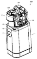
- Embodiment 1 of this invention It is an external appearance perspective view of the nebulizer in the use condition in Embodiment 1 of this invention. It is an external appearance perspective view showing the unit structural example of the nebulizer in Embodiment 1 of this invention. It is a figure which shows a mode that each unit of the nebulizer in Embodiment 1 of this invention was isolate
- FIG. 3 It is a block diagram which shows an example of the circuit structure of the nebulizer in Embodiment 1 of this invention.
- A is a cross-sectional view of the atomization unit shown in FIG. 3 on the IXA-IXA plane
- B is a cross-sectional view of the breath detection unit shown in FIG. 3 on the IXB-IXB plane
- C Is a partial cross-sectional view of the main unit shown in FIG. 3 on the IXC-IXC plane.
- FIG. 4 is a cross-sectional view of the breath detection unit shown in FIG. 3 on the XX plane. It is sectional drawing for demonstrating operation
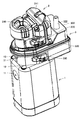
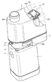
- the nebulizer 1000 includes a main unit 1, an atomization unit 2, an expiration detection unit 3, and a cover unit 4.
- the main unit 1 and the atomization unit 2 realize the basic function of the nebulizer, and the breath detection unit 3 realizes an additional function.
- the main unit 1 includes a power supply circuit and a control circuit, as will be described in detail later.
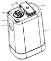
- a power switch 11 for switching ON / OFF of the power supply of the nebulizer 1000 is provided on the front surface of the main unit 1.
- two LEDs (Light Emitting Diodes) 12 and 13 for emitting different colors are provided on the upper surface.
- the LED 12 outputs green light, and the LED 13 outputs orange light. For example, the LED 12 is lit when the power is turned on, and the LED 13 is lit when the battery capacity is low (when the battery is low).
- the atomization unit 2 includes a chemical solution storage unit for storing a chemical solution and an atomization unit (mesh and vibrator) for atomizing the chemical solution.
- the atomization unit 2 is provided with a spray port 240 for spraying a chemical and an opening / closing operation unit 241 that can be opened and closed by the user.
- opening and closing the opening / closing operation unit 241 it is possible to easily supply the chemical solution to the chemical solution storage unit or to clean the chemical solution storage unit.
- the chemical solution can also be supplied by opening and closing the spray port 240.
- the expiration detection unit 3 detects the breathing state (exhalation, inspiration) of the user. And the atomization by an atomization part is performed only in the case of intake. In the present embodiment, for example, a respiratory state is detected by a pressure sensor.
- a second tube portion 322 connected to the first tube portion 321 (see FIG. 9 and the like) in the housing 300 is disposed.
- An LED 31 is also provided on the front surface of the breath detection unit 3. For example, the LED 31 is lit when the capacity of a button-type battery 350 (see FIG. 9 and the like) in the expiration detection unit 3 is low (when the battery is low).
- the cover unit 4 covers the entire atomization unit 2 and a part of the breath detection unit 3.
- the cover part 4 is an auxiliary tool for assisting breath detection and inhalation of a chemical solution, and is integrally formed of a resin material.
- the cover unit 4 is attached to the expiration detection unit 3 by being fitted into a fitting unit 320 provided on the side surface of the expiration detection unit 3.
- a packing is interposed between the cover part 4 and the breath detection unit 3. Thereby, the space inside cover part 4 and the exterior are kept airtight.
- a mouthpiece (suction port) 41 for the user to hold in the mouth can be attached to the cylindrical portion 420 (see FIG. 11 and the like) on the upper surface of the cover portion 4.
- the user holds the nebulizer 1000 in the state as shown in FIG. 1 and tilts it slightly toward the front so that the mouthpiece 41 of the cover 4 can be held.
- the atomized chemical liquid sprayed from the spray port 240 of the atomization unit 2 passes through the cylindrical portion 420 (see FIG. 11 and the like) and the mouthpiece 41.
- a ventilation part 42 for allowing the gas inside and outside the cover part 4 to vent is further arranged.
- the ventilation part 42 is formed so that gas is exhausted behind the nebulizer 1000.
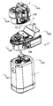
- the main unit 1, the breath detection unit 3 and the atomization unit 2 can be separated from each other.
- the breath detection unit 3 as a functional unit is mounted (inserted) between the main unit 1 and the atomization unit 2.
- the atomizing unit 2 and the breath detection unit 3 may be provided with attachments 230 and 330 for fixing the connection state with the unit located immediately below, respectively.
- the units can be connected or separated.
- connection terminals are provided on the connection surfaces between the units.
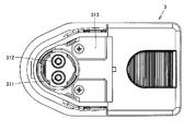
- connection terminals 101 and 102 are provided on the upper surface of main unit 1 (the connection surface with the lower surface of breath detection unit 3). Further, a convex portion 103 is provided for facilitating mounting and positioning of the expiration detection unit 3.
- connection terminals 311 and 312 that can contact the connection terminals 101 and 102 of the main unit 1 are provided on the lower surface (connection surface with the main unit 1) of the breath detection unit 3. Moreover, the recessed part 313 which can fit the convex part 103 of the main body unit 1 is provided.
- connection terminals 301 and 302 are provided on the upper surface of the breath detection unit 3 (connection surface with the atomization unit 2). Moreover, the convex part 303 for making mounting
- connection terminals 301 and 302 is the same as that of the connection terminals 101 and 102 of the main unit 1.
- the shape of the convex portion 303 is the same as that of the convex portion 103 of the main unit 1.
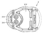
- connection terminals 211 and 212 that can come into contact with connection terminals 301 and 302 of breath detection unit 3 are provided on the lower surface (connection surface with breath detection unit 3) of atomization unit 2. Moreover, the recessed part 213 which can fit the convex part 303 of the breath detection unit 3 is provided.
- connection terminals 211 and 212 are the same as the connection terminals 311 and 312 of the breath detection unit 3.
- the shape of the recess 213 is the same as that of the recess 313 of the breath detection unit 3.
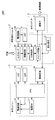
- main unit 1 includes a power supply circuit 14, a CPU (Central Processing Unit) 15 and an oscillation circuit 16 in addition to the power switch 11 and LEDs 12 and 13.
- CPU Central Processing Unit
- the power supply circuit 14 includes, for example, a battery and supplies power to each unit in the main unit 1.
- the CPU 15 controls each unit. Based on the control signal from the CPU 15, the oscillation circuit 16 outputs an oscillation signal to the breath detection unit 3 (switch circuit 36 described later).
- the oscillation signal is output for a certain time after the power switch 11 is pressed, for example.
- the measurement for a certain time may be performed by a timer (not shown).
- the atomization unit 2 includes a vibrator 21 that is driven to atomize the chemical.
- the vibrator 21 vibrates according to the oscillation signal.
- the breath detection unit 3 includes a power supply circuit 38, a pressure sensor 33, an amplifier circuit 34, a comparison circuit 35, a switch circuit 36, and a pseudo resistor 37 in addition to the LED 31.
- the pressure sensor 33 detects the atmospheric pressure accompanying breathing.
- the detected pressure signal is output to the amplifier circuit 34.
- the amplifier circuit 34 amplifies the pressure signal output from the pressure sensor 33.
- the amplified pressure signal is output to the comparison circuit 35.
- the comparison circuit 35 compares the value of the pressure signal output from the amplification circuit 34 (hereinafter “pressure value”) with a predetermined reference value, and outputs the result to the switch circuit 36. More specifically, if the pressure value is equal to or higher than the reference value (during expiration), a Low signal is output, and if the pressure value is less than the reference value (during inspiration), a High signal is output.
- the switch circuit 36 is configured by, for example, a field effect transistor (FET).
- FET field effect transistor
- the switch circuit 36 inputs the oscillation signal output from the oscillation circuit 16 of the main unit 1.
- the switch circuit 36 selects the output destination of the input oscillation signal according to the signal (High or Low) from the comparison circuit 35.
- the atomization unit 2 (vibrator 21) is selected as an output destination. Therefore, during intake, the oscillation signal is transferred to the vibrator 21 and the vibrator 21 vibrates. Thereby, a chemical
- the pseudo resistor 37 is selected as the output destination. Therefore, at the time of expiration, the oscillation signal is not transferred to the vibrator 21, so the vibrator 21 does not vibrate and no chemical is sprayed from the spray port 240.
- the expiration detection unit 3 has a configuration for detecting the user's breathing state (pressure sensor 33 and the like) and a configuration for causing the atomizing unit to atomize the chemical only in the case of inspiration (comparison circuit 35). , Switch circuit 36, etc.). Therefore, according to the nebulizer 1000, even if the oscillation circuit 16 outputs an oscillation signal continuously, the atomization unit 2 sprays intermittently (only during intake). As a result, the chemical liquid can be efficiently sprayed.
- the power supply circuit 38 of the breath detection unit 3 includes, for example, a button type battery 350 (FIG. 9). Power is supplied from the power supply circuit 38 to the pressure sensor 33, the amplification circuit 34, and the comparison circuit 35.
- the breath detection unit 3 is also provided with the power supply circuit 38, but when connected to the main unit 1, the power supply circuit 14 in the main unit 1 connects the breath detection unit 3 in the breath detection unit 3. Power may be supplied to each part.
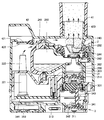
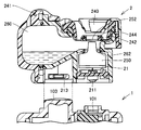
- FIGS. 9A to 9C show a cross section of the atomizing unit 2 along the line IXA-IXA shown in FIG. 3, and FIG. 9B shows an expiration detection unit along the line IXB-IXB shown in FIG. 3 shows a cross section.
- FIG. 9C partially shows a cross section of the main unit 1 along the line IXC-IXC shown in FIG.
- connection terminal 101 is included in the cross section of the main unit 1.
- cross section of the breath detection unit 3 includes the cross sections of the connection terminals 301 and 311, and the cross section of the atomization unit 2 includes the cross section of the connection terminal 211.
- the atomization unit 2 includes an ultrasonic mesh type atomization mechanism immediately below the spray port 240.
- the ultrasonic mesh type atomization mechanism includes a vibrator (piezoelectric element) 21, a step horn 250, and a mesh 252.
- the mesh 252 has a large number of fine holes, and is in contact with one end of the step horn 250 on its lower surface.
- the vibrator 21 vibrates by an oscillation signal obtained from the connection terminal 211. By propagating this vibration to the step horn 250, the chemical solution is atomized on the contact surface between the step horn 250 and the mesh 252.
- the atomized chemical liquid is ejected vigorously from the fine holes toward the spray port 240.
- a liquid reservoir 242 for storing liquid chemicals and drooling of the user is formed at the periphery of the spray port 240.
- the chemical solution and the drool stored in the liquid reservoir 242 are separated by a partition plate 244 so as not to be mixed into the mesh 252 located inside thereof.
- a chemical solution storage unit 260 for storing a chemical solution is formed inside the atomization unit 2.
- the medicinal solution stored in the medicinal solution storage unit 260 is atomized without being inclined by being inclined during use. For this reason, a watertight structure is provided by the O-ring 262 so that the chemical solution does not spill out into the apparatus.
- the concave part 213 formed in the lower part of the atomization unit 2 is fitted into the convex part 303 of the breath detection unit 3. Moreover, when the recessed part 213 and the convex part 303 are fitted, the connection terminal 211 will contact the connection terminal 301 of the breath detection unit 3, and these will be in electrical continuity.
- the breath detection unit 3 is provided with a sheet metal terminal 343 electrically connected to the connection terminal 301 and a sheet metal terminal 342 electrically connected to the connection terminal 311. . Since these sheet metal terminals 342 and 343 are electrically connected to the substrate 341, the main unit 1 and the atomizing unit 2 can be electrically connected. As described above, the substrate 341 and the sheet metal terminals 342 and 343 serve as a relay unit for electrically connecting the main unit 1 and the atomizing unit 2.
- the breath detection unit 3 further includes a substrate 344 on which the above-described circuit units (at least a part of the power supply circuit 38, the amplifier circuit 34, the comparison circuit 35, and the switch circuit 36) are assembled.
- a power line (not shown) is connected from the substrate 341 to the substrate 344, and both the substrates 341 and 344 are electrically connected.
- the substrates 341 and 344 and the sheet metal terminals 342 and 343 are built in the housing 300.
- the second pipe portion 322 provided so as to protrude from the housing 300 takes in the gas from the outside (exhalation of the user) or discharges the gas inside.
- the gas that has passed through the second tube portion 322 flows into the first tube portion 321 and is guided to the pressure sensor 33 provided on the substrate 344.
- the pressure sensor 33 detects the state of breathing by detecting the atmospheric pressure in the first tube portion 321.
- the exhalation detection unit includes a first tube unit 321, a second tube unit 322, and a pressure sensor 33.
- the configuration of the expiration detection unit is not limited to such a form.
- the recess 313 formed in the lower part of the breath detection unit 3 is fitted into the protrusion 103 of the main unit 1. Moreover, when the recessed part 313 and the convex part 103 are fitted, the connection terminal 311 will contact the connection terminal 101 of the main body unit 1, and these will be in a conduction
- FIGS. 10, 11 and 12 and FIG. 11 and 12 show cross sections of the nebulizer 1000 (excluding the main unit 1) taken along lines XI, XII-XI, and XII shown in FIG. 11 and 12 both include the cross sections shown in FIGS. 9A and 9B.
- an exhalation valve 421 for preventing inflow of gas from the outside is provided at the lower portion of the ventilation portion 42 of the cover portion 4.
- the exhalation-valve 421 is attached to the lower part of the ventilation part 42 of the cover part 4 via the attachment member 422, and is opened and closed by the atmospheric pressure in the cover part 4.
- a cylindrical part 420 for mounting the mouthpiece 41 is provided on the upper part of the cover part 4.
- gas flows from the cylindrical part 420 into the cover part 4. Then, the inflowing gas flows into the air path constituted by the first and second pipe portions 321 and 322, as indicated by arrows in FIG. In addition, the gas that has flowed in pushes up the exhalation valve 421. As a result, the exhalation valve 421 is opened, and the gas in the cover part 4 flows out through the exhalation valve 421 and the ventilation part 42.
- the pressure sensor 33 since the gas flows into the air path, the pressure sensor 33 outputs a voltage higher than the reference voltage. Therefore, the output of the comparison circuit 35 is a Low signal. In such a case, the oscillation signal is output to the pseudo resistor 37. Therefore, the oscillation signal does not reach the connection terminal 301 (302), and the vibrator 21 does not vibrate. Therefore, the drug solution in the drug solution storage unit 260 is not sprayed during expiration.
- the operation of the nebulizer 1000 at the time of inhalation (when the user inhales while holding the mouthpiece 41) will be described.
- the exhalation valve 421 When the user breathes in with the mouthpiece 41 held, the exhalation valve 421 is closed. Thereby, the inflow of the gas from the ventilation part 42 to the inside of the cover part 4 is suppressed. Moreover, since the gas which had been inside the cover part 4 is sucked up until then, the gas flows out from the air path.
- the output of the comparison circuit 35 is a High signal.
- the oscillation signal is transmitted to the substrate 341 via a power line (not shown).
- the oscillation signal is output from the substrate 341 to the connection terminal 301 (302) via the sheet metal terminal 343.
- an oscillation signal is transmitted to the vibrator 21 and the vibrator 21 vibrates. .
- the gas containing the chemical liquid atomized by the mesh 252 flows into the mouth of the user through the mouthpiece 41.
- nebulizer 2000 does not include exhalation detection unit 3 and includes main body unit 1 and atomization unit 2 that can be separated from main body unit 1.
- the nebulizer 2000 can be said to be a device that realizes only a basic function as a nebulizer. In the present embodiment, such a nebulizer is also referred to as a “basic specification nebulizer”.
- the nebulizer 2000 may have the same configuration as that of the mesh nebulizer NE-U22 manufactured and sold by the applicant, for example.
- an inhalation mask portion (not shown) for assisting inhalation may be mounted so as to cover the atomization unit 2 in place of the cover portion 4 described above. .
- nebulizer 2000 when oscillation circuit 16 of main unit 1 outputs an oscillation signal, it is transmitted to vibrator 21 of atomization unit 2 as it is. Therefore, when the oscillation signal is continuously output, the drug solution is continuously sprayed regardless of the user's breathing state.
- connection terminal 101 (102) and projection 103 on the upper surface of main unit 1 can be connected to connection terminal 211 (212) and recess 213 on the lower surface of atomizing unit 2, respectively. It is.
- connection terminals 101 and 102 and the convex portion 103 on the upper surface of the main unit 1 are the same as the shapes of the connection terminals 301 and 302 and the convex portion 303 on the upper surface of the breath detection unit 3, respectively.
- the main unit 1 and the atomization unit 2 can be connected both physically and electrically.
- the nebulizer 2000 has been described as a device that realizes only a basic function.
- the nebulizer 2000 is not limited to a device that realizes only a basic function as long as the two units can be separated.
- at least one of the main body unit 1 and the atomization unit 2 may include another configuration capable of realizing an additional function other than the basic function of atomization of a chemical solution.
- it is a condition that the apparatus is not enlarged by including other configurations.
- the breath detection unit is employed as a functional unit that can be attached to and detached from the basic nebulizer (the main unit and the atomization unit).
- the basic nebulizer the main unit and the atomization unit.
- power for controlling the strength of the spray is used.
- Adopt control unit is used.
- the configuration and operation other than the power control unit are basically the same as those of the nebulizer 1000 of the first embodiment. Therefore, only the parts different from the first embodiment will be described below.
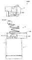
- nebulizer 1000A in the present embodiment includes a main body unit 1, an atomization unit 2, and a power control unit 5 that can be mounted between these units.
- the power control unit 5 has an operation unit 50 that is operated by the user to adjust the spray intensity on the front surface thereof.
- the operation unit 50 includes, for example, three switches for receiving instructions of three levels of strength, that is, a strong (High setting) switch 51, a normal switch 52, and a weak (Low setting) switch 53.
- the normal switch 52 may not be provided.
- FIG. 18 is a block diagram showing an example of the circuit configuration of the nebulizer 1000A.
- the configurations of the main unit 1 and the atomizing unit 2 are the same as those in the first embodiment.
- the power control unit 5 further includes an amplitude adjustment unit 57 for adjusting the spray amount per unit time by the atomization unit (vibrator 21, step horn 250, mesh 252) in addition to the operation unit 50.
- the amplitude adjusting unit 57 receives the oscillation signal from the oscillation circuit 16 of the main unit 1 and amplifies / reduces the input oscillation signal in accordance with an instruction from the user. That is, when the user presses the strong switch 51, the input oscillation signal is amplified. When the user presses the weak switch 53, the input oscillation signal is reduced. When the user presses the normal switch 52, the amplitude is not adjusted.
- the amplitude adjusting unit 57 includes, for example, a variable resistor 54, a switch terminal 55, and an operational amplifier 56 in order to realize the above function.
- a variable resistor 54 When the user presses one of the switches, one of the three switch terminals 55 is selected according to the pressed switch.
- the amplitude adjusting unit 57 outputs an oscillation signal whose amplitude has been adjusted to the vibrator 21.
- an appropriate spray amount or inhalation time can be selected according to the characteristics (viscosity) of the drug, the age of the user, or the physical condition of the user.
- An appropriate spray amount can be realized by setting High (strong switch 51) when the viscosity of the chemical stored in the chemical reservoir 260 is high, and conversely setting Low (weak switch 53) when low. it can.
- the High setting can be used, and if the user is a child or an elderly person, the Low setting can be used to obtain a spray amount suitable for the user.
- the High setting is set, and when the user inhales slowly, the Low setting is set so that the user selects an optimal inhalation time according to the user's physical condition and mood at that time. Can do.
- an appropriate spray amount can be set by setting High or Low. Or it can be an inhalation time.
- the configuration for allowing the power control unit 5 to be electrically connected to the main unit 1 and the atomization unit 2 may be the same as that of the breath detection unit 3.
- the upper surface of the power control unit 5 has a convex portion (not shown) having the same shape as the convex portion 303 of the breath detection unit 3, and the lower surface of the power control unit 5 has the breath detection unit 3. It is assumed that a concave portion (not shown) having the same shape as the concave portion 313 is provided.
- the spray amount and the suction time can be adjusted by adjusting the amplitude of the oscillation signal, but the frequency of the oscillation signal may be adjusted.
- an extension cord unit is adopted as a functional unit that can be attached to and detached from the basic specification nebulizer (main unit and atomizing unit).
- the configuration and operation other than the extension cord unit are basically the same as those in the first embodiment. Therefore, only the parts different from the first embodiment will be described below.
- nebulizer 1000B in the present embodiment includes a main body unit 1, an atomizing unit 2, and an extension cord unit 6 that can be mounted between these units.
- the extension cord unit 6 includes an extension cord 620 and a housing 600 that includes a storage portion for storing the extension cord 620.
- connection terminals 611 and 612 for connecting to the connection terminals 101 and 102 of the main unit 1 are disposed on the lower surface of the housing 600.
- One end of the extension cord 620 is connected to the connection terminals 611 and 612.
- the other end of the extension cord 620 is connected to the connection terminals 601 and 602.
- connection terminals 611 and 612 have the same shape as the connection terminals 311 and 312 of the breath detection unit 3.
- the connection terminals 601 and 602 have the same shape as the connection terminals 301 and 302 of the breath detection unit 3. Therefore, even if the main body unit 1 and the atomization unit 2 are separated, the extension cord unit 6 can be electrically connected.
- the extension cord unit 6 fulfills the function of the relay unit described in the first and second embodiments.
- the atomization unit 2 (or an unillustrated suction mask portion) can be gripped and used while the main unit 1 is placed on the desk. As a result, it is possible to facilitate inhalation while the patient is lying. In addition, even a user with weak grip strength can inhale medicine alone.
- Embodiments 1 to 3 of the present invention the functional unit for changing the spray state (the expiration detection unit, the power control unit) and the functional unit for changing the usage method are added to the nebulizer of the basic specification. (Extension cord unit) can be inserted. Thereby, the additional function suitable for the characteristic of a user or a chemical
- the nebulizer of the basic specification it is only necessary to purchase an additional functional unit that can fulfill the desired additional function.
- the vibrator and mesh of the atomizing unit are expensive. Therefore, by adding the functional unit to the nebulizer of the basic specification, it is possible to reduce the financial burden on the user. As a result, the nebulizer owned by the user can be used efficiently.
- the apparatus can be reduced in size as compared with the case where a plurality of additional functions are incorporated in the nebulizer body (when the unit cannot be separated).
- the user can use the basic nebulizer while the functional unit is out for repair. Therefore, the inconvenience that the nebulizer cannot be used can be solved even when it is necessary to inhale the medicine urgently at the time of the attack.
- nebulizers are used at home and in the hospital, and when nebulizers are carried in preparation for emergency inhalation.
- a desired functional unit can be inserted and used, and in the latter case, only the basic specification nebulizer can be carried.
- the user can use the nebulizer in various forms depending on the usage situation.
- the manufacturer can manufacture and sell various functional units as a single unit.
- the functional unit is not limited to the examples shown in the first to third embodiments. If the functional unit has at least a relay unit (configuration for electrically connecting the main body unit and the atomizing unit) as described in the first embodiment, it realizes other additional functions. It may be.
- a unit that detects the amplitude of the oscillation signal at the time of no adjustment and adjusts the amplitude of the oscillation signal according to the detected amplitude may be provided as the functional unit that changes the spray state of the atomization unit.
- the impedance of the vibrator may change depending on the type of chemical and drought. When the impedance changes, the oscillation signal is affected. Therefore, when the amplitude of the oscillation signal without adjustment is smaller than the reference value by a predetermined value or more, the amplitude of the oscillation signal may be amplified. This is because in such a case, the chemical liquid to be atomized is considered to have a higher viscosity than the standard.
- the amplitude of the oscillation signal without adjustment is larger than the reference value by a predetermined value or more, the amplitude of the oscillation signal may be reduced. This is because in such a case, the chemical liquid to be atomized is considered to have a lower viscosity than the standard.
- the change in the amplitude of the oscillation signal may be detected, and the operation of the main unit may be stopped when the amplitude suddenly increases.
- a second atomizing unit for spraying a chemical liquid different from the chemical liquid sprayed by the atomizing unit may be provided as a functional unit for changing the usage method of the nebulizer. Thereby, it becomes applicable also to the treatment method which inhales two different types of chemical
- a unit having an informing unit for informing (for example, displaying) inhalation time progress information and optimum inhalation timing may be provided.
- Embodiments 1 to 3 the example in which one functional unit is inserted between the main unit and the atomizing unit has been described. However, since all the functional units have connection terminals with a uniform shape, it is possible to insert two or more functional units. For example, a power control unit may be inserted on the main unit side, and an expiration detection unit may be inserted on the atomization unit side. In that case, the oscillation signal after power control can be output to the atomization unit according to the breathing state.
- a mesh nebulizer has been described as an example, but an ultrasonic nebulizer may be used.
Landscapes
- Health & Medical Sciences (AREA)
- Engineering & Computer Science (AREA)
- Animal Behavior & Ethology (AREA)
- Anesthesiology (AREA)
- Biomedical Technology (AREA)
- Heart & Thoracic Surgery (AREA)
- Hematology (AREA)
- Life Sciences & Earth Sciences (AREA)
- General Health & Medical Sciences (AREA)
- Public Health (AREA)
- Veterinary Medicine (AREA)
- Pulmonology (AREA)
- Bioinformatics & Cheminformatics (AREA)
- Special Spraying Apparatus (AREA)
Abstract
Description
(概略について)
はじめに、図1~図2を参照して、本実施の形態におけるネブライザ1000の概略について説明する。本実施の形態におけるネブライザ1000は、いわゆるメッシュ式であると想定する。
図8を参照して、本体ユニット1は、上記電源スイッチ11およびLED12,13に加え、電源回路14、CPU(Central Processing Unit)15および発振回路16を含む。
図9(A)~(C)を参照して、霧化ユニット2と呼気検知ユニット3の内部構造の一例について説明する。図9(A)は、図3に示したIXA-IXA線に沿った霧化ユニット2の断面を示し、図9(B)は、図3に示したIXB-IXB線に沿った呼気検知ユニット3の断面を示している。また、図9(C)は、図3に示したIXC-IXC線に沿った本体ユニット1の断面を部分的に示している。
次に、図10、図11および図12の断面図、および、図13を参照して、使用時におけるネブライザ1000の動作について説明する。図11および図12は、図1に示したXI,XII-XI,XII線に沿ったネブライザ1000(本体ユニット1を除く)の断面を示している。なお、図11および図12の断面は、いずれも、図9(A),(B)に示した断面を含んでいる。
機能ユニットすなわち呼気検知ユニット3を装着しない場合のネブライザの構成について説明する。
次に、本発明の実施の形態2について説明する。
次に、本発明の実施の形態3について説明する。
以上のように、本発明の実施の形態1~3によると、基本仕様のネブライザに、噴霧状態を変えるための機能ユニット(呼気検知ユニット,パワー制御ユニット)や、使用方法を変えるための機能ユニット(延長コードユニット)を挿入することができる。これにより、薬液の霧化という基本機能に、ユーザや薬剤の特性に適した付加的機能を容易に追加することができる。
<変形例>
なお、機能ユニットは、実施の形態1~3に示した例に限定されない。機能ユニットは、実施の形態1で説明したような中継部(本体ユニットと霧化ユニットとを電気的に接続するための構成)を少なくとも有していれば、他の付加的機能を実現するものであってもよい。
Claims (10)
- 薬液を噴霧するためのネブライザ(1000,1000A,1000B)であって、
第1および第2のユニット(2,1)を備え、
前記第1および第2のユニットは、分離可能であり、
前記第1のユニットは、
薬液を貯留するための貯留部(260)と、
前記貯留部内の薬液を霧化することにより、薬液を噴霧するための霧化部(21)とを含み、
前記第2のユニットは、前記霧化部を動作させる制御を行なうための制御部(15)を含み、
ネブライザの付加的機能を実現するための第3のユニット(3,5,6)をさらに備え、
前記第3のユニットは、前記第1のユニットと前記第2のユニットとの間に着脱可能である、ネブライザ。 - 前記第3のユニットは、前記制御部と前記霧化部とを電気的に接続するための中継部(341,342,343)を含む、請求の範囲第1項に記載のネブライザ。
- 前記第3のユニットは、前記付加的機能として、前記霧化部による噴霧状態を変更する機能を実現する、請求の範囲第2項に記載のネブライザ。
- 前記第3のユニットは、
ユーザの呼吸状態を検知するための検知部(33)と、
前記検知部による検知結果に応じて、吸気の場合にのみ、前記霧化部に薬液を霧化させるための霧化制御部とをさらに含む、請求の範囲第3項に記載のネブライザ。 - 前記霧化部は、薬液を霧化するために駆動される振動子(21)を有し、
前記第2のユニットは、前記制御部からの指示に応じて、前記振動子を振動させるための発振信号を出力する発振部(16)をさらに含み、
前記霧化制御部は、前記発振部が出力した前記発振信号を入力し、吸気の場合にのみ入力した前記発振信号を前記振動子に転送する、請求の範囲第4項に記載のネブライザ。 - 前記第3のユニットは、前記霧化部による単位時間当たりの噴霧量を調整するための調整部(57)を有する、請求の範囲第3項に記載のネブライザ。
- 前記霧化部は、薬液を霧化するために駆動される振動子(21)を有し、
前記第2のユニットは、前記制御部からの指示に応じて、前記振動子を振動させるための発振信号を出力する発振部(16)をさらに含み、
前記調整部は、前記発振部が出力した前記発振信号の振幅または周波数を調整し、調整後の発振信号を前記振動子に転送する、請求の範囲第6項に記載のネブライザ。 - 前記第3のユニットは、単位時間当たりの噴霧量について、ユーザからの指示を受け付けるための操作部(50)をさらに含む、請求の範囲第6項に記載のネブライザ。
- 前記第3のユニットは、前記付加的機能として、前記ネブライザの使用方法を変更する機能を実現する、請求の範囲第2項に記載のネブライザ。
- 第1および第2のユニット(2,1)を備えたネブライザに着脱可能な、ネブライザの付加的機能を実現するための機能ユニット(3,5,6)であって、前記第1のユニットは、薬液を貯留するための貯留部(260)と、前記貯留部内の薬液を霧化することにより、薬液を噴霧するための霧化部(21)とを含み、前記第2のユニットは、前記霧化部を動作させる制御を行なうための制御部(15)を含んでおり、
前記制御部と前記霧化部とを電気的に接続するための中継部(341,342,343)を備える、機能ユニット。
Priority Applications (4)
| Application Number | Priority Date | Filing Date | Title |
|---|---|---|---|
| RU2011141826/14A RU2524130C2 (ru) | 2009-03-17 | 2010-01-28 | Распылители и функциональные модули, присоединяемые к распылителю |
| CN201080012397.6A CN102355915B (zh) | 2009-03-17 | 2010-01-28 | 雾化器及能够相对于雾化器装卸的功能单元 |
| DE112010001198T DE112010001198T5 (de) | 2009-03-17 | 2010-01-28 | Inhalatoren und Funktionseinheiten, die an Inhalator anbringbar sind |
| US13/207,881 US9155847B2 (en) | 2009-03-17 | 2011-08-11 | Nebulizers and function units attachable to nebulizer |
Applications Claiming Priority (2)
| Application Number | Priority Date | Filing Date | Title |
|---|---|---|---|
| JP2009064615A JP5267245B2 (ja) | 2009-03-17 | 2009-03-17 | ネブライザ、および、ネブライザに着脱可能な機能ユニット |
| JP2009-064615 | 2009-03-17 |
Related Child Applications (1)
| Application Number | Title | Priority Date | Filing Date |
|---|---|---|---|
| US13/207,881 Continuation US9155847B2 (en) | 2009-03-17 | 2011-08-11 | Nebulizers and function units attachable to nebulizer |
Publications (1)
| Publication Number | Publication Date |
|---|---|
| WO2010106834A1 true WO2010106834A1 (ja) | 2010-09-23 |
Family
ID=42739500
Family Applications (1)
| Application Number | Title | Priority Date | Filing Date |
|---|---|---|---|
| PCT/JP2010/051088 Ceased WO2010106834A1 (ja) | 2009-03-17 | 2010-01-28 | ネブライザ、および、ネブライザに着脱可能な機能ユニット |
Country Status (6)
| Country | Link |
|---|---|
| US (1) | US9155847B2 (ja) |
| JP (1) | JP5267245B2 (ja) |
| CN (1) | CN102355915B (ja) |
| DE (1) | DE112010001198T5 (ja) |
| RU (1) | RU2524130C2 (ja) |
| WO (1) | WO2010106834A1 (ja) |
Cited By (4)
| Publication number | Priority date | Publication date | Assignee | Title |
|---|---|---|---|---|
| JP2015062454A (ja) * | 2013-09-24 | 2015-04-09 | オムロンヘルスケア株式会社 | ネブライザ用メッシュ選定方法、装置、及びプログラム |
| WO2016152199A1 (ja) * | 2015-03-25 | 2016-09-29 | オムロンヘルスケア株式会社 | 超音波式ネブライザ |
| WO2016152198A1 (ja) * | 2015-03-25 | 2016-09-29 | オムロンヘルスケア株式会社 | 超音波式ネブライザ |
| WO2016152197A1 (ja) * | 2015-03-25 | 2016-09-29 | オムロンヘルスケア株式会社 | 超音波式ネブライザ |
Families Citing this family (27)
| Publication number | Priority date | Publication date | Assignee | Title |
|---|---|---|---|---|
| WO2012056398A1 (en) | 2010-10-29 | 2012-05-03 | Koninklijke Philips Electronics N.V. | A nebulizer, a control unit for controlling the same, and a method of controlling a nebulizer |
| DE102011113126B4 (de) * | 2011-09-14 | 2015-05-13 | Olaf Storz | Leistungseinheit und medizinisches Handgerät |
| GB2558102B (en) * | 2013-12-20 | 2018-11-28 | Fisher & Paykel Healthcare Ltd | Humidification system connections |
| EP2910268A1 (en) * | 2014-02-25 | 2015-08-26 | PARI Pharma GmbH | Inhalator and inhalator set |
| US9278365B2 (en) | 2014-03-26 | 2016-03-08 | S.C. Johnson & Son, Inc. | Volatile material dispenser and method of emitting a volatile material |
| CN104623770A (zh) * | 2014-11-21 | 2015-05-20 | 无锡科思电子科技有限公司 | 一种自适应雾化装置 |
| TWI609706B (zh) * | 2015-06-11 | 2018-01-01 | 台達電子工業股份有限公司 | 霧化系統、霧化器及其驅動方法 |
| EP3103496B1 (en) * | 2015-06-11 | 2018-08-15 | Delta Electronics, Inc. | Nebulization system |
| EP3368112B1 (en) | 2015-10-30 | 2019-10-23 | Johnson & Johnson Consumer Inc. | Aseptic aerosol misting device |
| CA3003438C (en) | 2015-10-30 | 2024-01-02 | Johnson & Johnson Consumer Inc. | Aseptic aerosol misting device |
| MA43112A (fr) | 2015-10-30 | 2018-09-05 | Johnson & Johnson Consumer Inc | Pulvérisateur d'aérosol aseptique de dose unitaire |
| EP3397329B1 (en) * | 2015-12-28 | 2023-03-08 | Koninklijke Philips N.V. | Air-flow in a nebulizer head |
| CN105477752B (zh) * | 2016-01-05 | 2019-06-14 | 湖南明康中锦医疗科技发展有限公司 | 可检测呼吸状态的雾化器 |
| WO2018022660A2 (en) * | 2016-07-26 | 2018-02-01 | Prolitec Inc. | Air treatment appliance |
| US10675373B2 (en) * | 2016-07-27 | 2020-06-09 | Newmarket Concepts, Llc | Fragrance dispenser having a disposable piezoelectric cartridge with a snap-in bottle containing aromatic liquid |
| EA038837B1 (ru) * | 2016-08-04 | 2021-10-27 | Джапан Тобакко Инк. | Ароматический ингалятор |
| JP6776761B2 (ja) * | 2016-09-20 | 2020-10-28 | オムロンヘルスケア株式会社 | メッシュ式ネブライザおよび薬液パック |
| CN109091729B (zh) * | 2017-06-20 | 2021-02-02 | 台达电子工业股份有限公司 | 具有按压式药杯的喷雾器 |
| CN107213538B (zh) * | 2017-07-12 | 2023-03-21 | 圣诺生物医药技术(广州)有限公司 | 雾化吸入给药用的储药及雾化装置 |
| TWI653064B (zh) * | 2017-08-30 | 2019-03-11 | 心誠鎂行動醫電股份有限公司 | 霧化器及其噴嘴組件 |
| US10786633B2 (en) | 2017-09-08 | 2020-09-29 | Hcmed Innovations Co., Ltd. | Nebulizer and nozzle assembly thereof |
| JP7053004B2 (ja) * | 2018-02-05 | 2022-04-12 | 株式会社星光技研 | 超音波式噴霧器 |
| EP3628354A1 (en) * | 2018-09-27 | 2020-04-01 | Ttp Plc. | Aerosol delivery system with perforate membrane |
| EP4007627B1 (en) * | 2019-08-02 | 2024-02-14 | Stamford Devices Limited | Nebulizer comprising a manually adjustable user interface |
| GB2600980B (en) * | 2020-11-14 | 2024-03-06 | Inspired Ventilation Ltd | A breathing system for a patient to breathe through and inhale a substance from |
| CN116173359B (zh) * | 2022-12-13 | 2025-12-23 | 深圳市尚进电子科技有限公司 | 一种药物雾化吸入装置及其控制系统和控制方法 |
| CN116328140A (zh) * | 2023-01-09 | 2023-06-27 | 湖南明康中锦医疗科技股份有限公司 | 一种同步雾化控制系统及控制方法与呼吸湿化治疗设备 |
Citations (5)
| Publication number | Priority date | Publication date | Assignee | Title |
|---|---|---|---|---|
| JPS61179158A (ja) * | 1984-10-16 | 1986-08-11 | ユニバ−シテイ オブ オ−クランド | 投与方法及び/又はデイスペンサ− |
| JPH06190044A (ja) * | 1992-09-11 | 1994-07-12 | Medic Aid Ltd | 薬剤給送装置 |
| JP2003102837A (ja) * | 2001-09-28 | 2003-04-08 | Omron Corp | 霧化装置用吸入補助具およびこれを備えた霧化装置 |
| JP2005102899A (ja) * | 2003-09-30 | 2005-04-21 | Alfresa Pharma Corp | 超音波霧化装置 |
| JP2005278742A (ja) * | 2004-03-29 | 2005-10-13 | A & D Co Ltd | 霧放出器 |
Family Cites Families (14)
| Publication number | Priority date | Publication date | Assignee | Title |
|---|---|---|---|---|
| US6029659A (en) * | 1995-04-17 | 2000-02-29 | Solar Shield Corporation | Inhalation device with counter |
| US5511539A (en) * | 1995-06-19 | 1996-04-30 | Lien; Su-Chu | Dose inhaler |
| WO2004096328A1 (ja) * | 1995-07-12 | 2004-11-11 | Hiroyuki Yokoi | ハンディ型吸入器 |
| US6234167B1 (en) * | 1998-10-14 | 2001-05-22 | Chrysalis Technologies, Incorporated | Aerosol generator and methods of making and using an aerosol generator |
| US6283118B1 (en) * | 1999-10-13 | 2001-09-04 | Hsueh-Yu Lu | Ultrasonic nebulizer |
| GB0026646D0 (en) * | 2000-10-31 | 2000-12-13 | Glaxo Group Ltd | Medicament dispenser |
| JP4590128B2 (ja) | 2001-05-18 | 2010-12-01 | 株式会社モリタ製作所 | 機能モジュール型の歯科用診療機器、この診療機器用の機能モジュール、この機能モジュールを用いる歯科用診療装置及び診療用機能モジュールユニット |
| JP2005034021A (ja) * | 2003-07-17 | 2005-02-10 | Seiko Epson Corp | 電子タバコ |
| US7721729B2 (en) * | 2005-03-09 | 2010-05-25 | Ric Investments, Llc | Nebulizing drug delivery device for ventilator |
| US8056557B2 (en) * | 2005-03-09 | 2011-11-15 | Ric Investments, Llc | Nebulizing drug delivery device with barrier |
| DE102005024779B4 (de) | 2005-05-31 | 2008-02-21 | Pari GmbH Spezialisten für effektive Inhalation | Atemzuggesteuerte Inhalationstherapievorrichtung |
| CN2905088Y (zh) * | 2006-04-10 | 2007-05-30 | 陈清甫 | 便携式雾化给药装置 |
| US7673812B2 (en) * | 2007-01-24 | 2010-03-09 | Taidoc Technology Corporation | Ultrasonic nebulizer apparatus and method for adjusting an operation frequency and checking an operating state thereof |
| CN201067728Y (zh) * | 2007-07-17 | 2008-06-04 | 朱晓春 | 一种口吸式家用雾化器 |
-
2009
- 2009-03-17 JP JP2009064615A patent/JP5267245B2/ja not_active Expired - Fee Related
-
2010
- 2010-01-28 DE DE112010001198T patent/DE112010001198T5/de active Pending
- 2010-01-28 RU RU2011141826/14A patent/RU2524130C2/ru active
- 2010-01-28 WO PCT/JP2010/051088 patent/WO2010106834A1/ja not_active Ceased
- 2010-01-28 CN CN201080012397.6A patent/CN102355915B/zh not_active Expired - Fee Related
-
2011
- 2011-08-11 US US13/207,881 patent/US9155847B2/en active Active
Patent Citations (5)
| Publication number | Priority date | Publication date | Assignee | Title |
|---|---|---|---|---|
| JPS61179158A (ja) * | 1984-10-16 | 1986-08-11 | ユニバ−シテイ オブ オ−クランド | 投与方法及び/又はデイスペンサ− |
| JPH06190044A (ja) * | 1992-09-11 | 1994-07-12 | Medic Aid Ltd | 薬剤給送装置 |
| JP2003102837A (ja) * | 2001-09-28 | 2003-04-08 | Omron Corp | 霧化装置用吸入補助具およびこれを備えた霧化装置 |
| JP2005102899A (ja) * | 2003-09-30 | 2005-04-21 | Alfresa Pharma Corp | 超音波霧化装置 |
| JP2005278742A (ja) * | 2004-03-29 | 2005-10-13 | A & D Co Ltd | 霧放出器 |
Cited By (12)
| Publication number | Priority date | Publication date | Assignee | Title |
|---|---|---|---|---|
| JP2015062454A (ja) * | 2013-09-24 | 2015-04-09 | オムロンヘルスケア株式会社 | ネブライザ用メッシュ選定方法、装置、及びプログラム |
| WO2016152199A1 (ja) * | 2015-03-25 | 2016-09-29 | オムロンヘルスケア株式会社 | 超音波式ネブライザ |
| WO2016152198A1 (ja) * | 2015-03-25 | 2016-09-29 | オムロンヘルスケア株式会社 | 超音波式ネブライザ |
| WO2016152197A1 (ja) * | 2015-03-25 | 2016-09-29 | オムロンヘルスケア株式会社 | 超音波式ネブライザ |
| JP2016182192A (ja) * | 2015-03-25 | 2016-10-20 | オムロンヘルスケア株式会社 | 超音波式ネブライザ |
| JP2016182195A (ja) * | 2015-03-25 | 2016-10-20 | オムロンヘルスケア株式会社 | 超音波式ネブライザ |
| JP2016182191A (ja) * | 2015-03-25 | 2016-10-20 | オムロンヘルスケア株式会社 | 超音波式ネブライザ |
| CN107206192A (zh) * | 2015-03-25 | 2017-09-26 | 欧姆龙健康医疗事业株式会社 | 超声波式雾化器 |
| CN107206192B (zh) * | 2015-03-25 | 2020-03-31 | 欧姆龙健康医疗事业株式会社 | 超声波式雾化器 |
| US10744279B2 (en) | 2015-03-25 | 2020-08-18 | Omron Healthcare Co., Ltd. | Ultrasonic nebulizer |
| US10758685B2 (en) | 2015-03-25 | 2020-09-01 | Omron Healthcare Co., Ltd. | Ultrasonic nebulizer |
| US10799902B2 (en) | 2015-03-25 | 2020-10-13 | Omron Healthcare Co., Ltd. | Ultrasonic nebulizer |
Also Published As
| Publication number | Publication date |
|---|---|
| DE112010001198T5 (de) | 2012-04-26 |
| JP5267245B2 (ja) | 2013-08-21 |
| RU2524130C2 (ru) | 2014-07-27 |
| US9155847B2 (en) | 2015-10-13 |
| JP2010213920A (ja) | 2010-09-30 |
| CN102355915A (zh) | 2012-02-15 |
| US20110290241A1 (en) | 2011-12-01 |
| RU2011141826A (ru) | 2013-04-27 |
| CN102355915B (zh) | 2014-09-10 |
Similar Documents
| Publication | Publication Date | Title |
|---|---|---|
| JP5267245B2 (ja) | ネブライザ、および、ネブライザに着脱可能な機能ユニット | |
| JP5439629B1 (ja) | 吸入装置 | |
| CN100569310C (zh) | 吸入设备 | |
| JP5746625B2 (ja) | 音声指示を供給する呼吸器系薬物送達装置 | |
| JP2006212203A (ja) | 吸入装置、及び液剤吐出カートリッジ | |
| JP4846976B2 (ja) | 吸入器の機能を改善するためのアダプタ | |
| CN213048754U (zh) | 主动递送式吸入给药装置 | |
| US6705312B2 (en) | Inhalator attachment and nebulizer equipped with same | |
| US11752277B2 (en) | Nebulization device having dual modules | |
| US8371289B2 (en) | Inhaler | |
| JP2020500632A (ja) | 吸入器 | |
| JP5328242B2 (ja) | 薬剤吐出装置の洗浄装置 | |
| JP2006255308A (ja) | 吸入器 | |
| JP4695940B2 (ja) | 吸入装置 | |
| CN210933209U (zh) | 超声科雾化器 | |
| EP4282452B1 (en) | Nebulizer with detecting structure | |
| CN222623473U (zh) | 一种佩戴式便携电子雾化装置 | |
| CN116649658A (zh) | 一种新风超声波雾化医用保健口罩装置 | |
| JP2006198127A (ja) | 吸入装置 | |
| CN121288107A (zh) | 一种高精度呼吸感应的雾化器 | |
| KR20230111092A (ko) | 에어로졸 흡입기 | |
| HK40007762A (en) | Inhaler | |
| JP2006280802A (ja) | 吸入装置 |
Legal Events
| Date | Code | Title | Description |
|---|---|---|---|
| WWE | Wipo information: entry into national phase |
Ref document number: 201080012397.6 Country of ref document: CN |
|
| 121 | Ep: the epo has been informed by wipo that ep was designated in this application |
Ref document number: 10753329 Country of ref document: EP Kind code of ref document: A1 |
|
| WWE | Wipo information: entry into national phase |
Ref document number: 112010001198 Country of ref document: DE Ref document number: 1120100011982 Country of ref document: DE |
|
| ENP | Entry into the national phase |
Ref document number: 2011141826 Country of ref document: RU Kind code of ref document: A |
|
| 122 | Ep: pct application non-entry in european phase |
Ref document number: 10753329 Country of ref document: EP Kind code of ref document: A1 |