WO2010106696A1 - 連続鋳造方法及び連続鋳造鋳型 - Google Patents
連続鋳造方法及び連続鋳造鋳型 Download PDFInfo
- Publication number
- WO2010106696A1 WO2010106696A1 PCT/JP2009/056215 JP2009056215W WO2010106696A1 WO 2010106696 A1 WO2010106696 A1 WO 2010106696A1 JP 2009056215 W JP2009056215 W JP 2009056215W WO 2010106696 A1 WO2010106696 A1 WO 2010106696A1
- Authority
- WO
- WIPO (PCT)
- Prior art keywords
- casting
- taper
- short side
- continuous casting
- side mold
- Prior art date
Links
Images


Classifications
-
- B—PERFORMING OPERATIONS; TRANSPORTING
- B22—CASTING; POWDER METALLURGY
- B22D—CASTING OF METALS; CASTING OF OTHER SUBSTANCES BY THE SAME PROCESSES OR DEVICES
- B22D11/00—Continuous casting of metals, i.e. casting in indefinite lengths
- B22D11/04—Continuous casting of metals, i.e. casting in indefinite lengths into open-ended moulds
- B22D11/041—Continuous casting of metals, i.e. casting in indefinite lengths into open-ended moulds for vertical casting
-
- B—PERFORMING OPERATIONS; TRANSPORTING
- B22—CASTING; POWDER METALLURGY
- B22D—CASTING OF METALS; CASTING OF OTHER SUBSTANCES BY THE SAME PROCESSES OR DEVICES
- B22D11/00—Continuous casting of metals, i.e. casting in indefinite lengths
- B22D11/16—Controlling or regulating processes or operations
- B22D11/168—Controlling or regulating processes or operations for adjusting the mould size or mould taper
-
- B—PERFORMING OPERATIONS; TRANSPORTING
- B22—CASTING; POWDER METALLURGY
- B22D—CASTING OF METALS; CASTING OF OTHER SUBSTANCES BY THE SAME PROCESSES OR DEVICES
- B22D11/00—Continuous casting of metals, i.e. casting in indefinite lengths
- B22D11/16—Controlling or regulating processes or operations
- B22D11/20—Controlling or regulating processes or operations for removing cast stock
Definitions
- the present invention relates to a continuous casting method and continuous casting mold for continuously casting molten metal.
- molten metal such as steel
- the molten metal part in contact with the mold is solidified to form a solidified shell, which is pulled out below the mold, and then cooled secondary below the mold. Solidification proceeds in the band and finally a continuous cast slab is formed.
- the mold is formed of a water-cooled copper plate on the side in contact with the molten metal.
- a continuous casting apparatus for casting a slab it has two long-side mold plates and two short-side mold plates, and the width of the short-side mold plate is approximately equal to the thickness of a cast piece to be cast.
- the continuous casting mold is formed by assembling the two long side mold plates so as to sandwich the two short side mold plates.
- the solidified shell solidifies and contracts as solidification proceeds. Therefore, the solidified shell that has started solidification at the meniscus position of the molten metal in the mold contracts when it reaches the lower end of the mold, and the width and thickness of the slab during solidification are smaller than the meniscus position. .
- the amount of solidification shrinkage in the slab width direction is large. If there is a gap between the mold and the solidified shell at the bottom of the mold due to the solidification shrinkage of the solidified shell, heat removal from the solidified shell to the mold will be hindered, and sufficient cooling of the mold will not be possible.
- a taper is provided at least on the short side of the mold. Providing the taper means that the distance between the lower ends of the mold is reduced with respect to the distance between the opposing short sides with respect to the distance at the meniscus position above the mold. In the present invention, as shown in FIG.
- W 0 may be anywhere as long as it has a fixed length according to a certain width.
- the upper end width of the mold and the lower end width of the mold can be used.
- W 0 (m) was defined as the meniscus width (W M ).
- the short side taper amount is too small, the contact between the solidified shell and the short side mold plate will be uneven, cooling imbalance will occur, the solidified shell growth will be uneven, the slab surface due to molten metal static pressure Cracking occurs.
- the short side taper amount is smaller than the appropriate amount, in the thickness distribution of the solidified shell near the lower end of the mold, as shown in FIG. Longitudinal cracks are likely to occur on the slab surface corresponding to this part.
- the short side taper amount is too large, the contact between the solidified shell and the short side mold plate becomes strong, excessive stress is applied to the solidified shell, and breakage of the solidified shell and breakout due to shell breakage occur. .
- the mold life may be reduced due to an increase in frictional force between the solidified shell and the mold.
- an appropriate short side taper for example, in Japanese Patent Application Laid-Open No. 2005-21936, it is said that operation is performed with a short side taper ratio ⁇ n of 0.7 to 1.3% / m.
- the surface (hereinafter also referred to as “taper surface 6”) of the conventional short-side mold plate 2 facing the solidified shell is processed in a plane from the upper part to the lower part as shown in FIG.
- the solidification shrinkage rate of the solidification shell is not constant at each position in the casting direction in the mold, and the solidification shrinkage rate is fast near the meniscus, and the solidification shrinkage rate becomes slower as it approaches the lower end of the mold.
- Japanese Patent Laid-Open No. 2-247059 discloses a taper control method for controlling the taper of the mold short side as a curved surface.
- the short side mold is supported at at least three points on the back surface and deformed.
- a pressure device is attached to at least one of the three points, for example, the central portion, and the surface of the short side copper plate and the free contraction profile are matched in advance and during operation, so that more uniform heat removal is possible.
- the maximum amount of deflection reaches 0.33 to 0.83 mm, which is considered to be a sufficient amount considering the amount of solidification shrinkage of the molten steel.
- the optimum short side taper is obtained by theoretical analysis. The optimum short side taper depends on the distance Z along the casting direction from the meniscus and the casting speed V. The optimum taper rate (% / m) is proportional to Z ⁇ 1/2 and is proportional to (4-V) (m / min). According to Example 1 and FIG.
- the short side of the mold having a cross-sectional dimension of 20.8 cm ⁇ 105 cm is formed into a shape having a taper of three stages, and the taper rate is 2% / m, 0.7% / m, 0.4% / m.
- the short side of the mold having a cross-sectional dimension of 22 cm ⁇ 124 cm is formed into a shape having a three-step taper, and the taper rate is 4% / m, 1.3% / m,. 8% / m.
- a mold having a taper of two stages or three or more stages in the casting direction is called a multistage taper mold
- a short side mold plate having such a taper is called a multistage taper short side mold plate.
- the higher the casting speed the higher the productivity.
- the casting speed has increased from around 2.0 m / min to about 3.0 m / min recently.
- the optimum shape of the multistage tapered short side mold plate changes as the casting speed increases, and the casting method using the multistage tapered short side mold plate also changes. For example, according to Japanese Patent Laid-Open No.
- the short-side mold plate 2 has a short-side driving device 4 for moving the short-side mold plate 2 in the long-side direction, and the short-side mold plate 2 is sandwiched between the long-side mold plates 3.
- the slab width can be changed during casting. That is, cast pieces having various widths can be cast using the same continuous casting mold 1 without exchanging both the long side mold plate 3 and the short side mold plate 2.
- Japanese Patent Application Laid-Open No. 2006-346735 and Japanese Patent Application Laid-Open No. 2006-34636 describe a method for estimating the solidification behavior of a slab in a mold by calculation.
- the speed is set to an arbitrary value
- the thickness of the solidified shell at each part of the four rounds of the mold is calculated. Based on this result, the ratio between the maximum and minimum values of the solidified shell thickness at the lower end of the mold, and between the solidified shell and the mold It is said that the binding force and the gap amount can be obtained.
- the preferred degree of curvature of the short side mold plate decreases as the casting speed increases. Therefore, as the short side mold plate used for continuous casting where the maximum casting speed V M (m / min) for casting is high, a short side plate formed by a short side taper with a small degree of curvature is used.
- slab continuous casting casting can be performed in accordance with various casting widths by using the same short side mold plate and changing the position of the short side mold plate in the mold. Casting slabs of various casting widths using a short side mold plate with a short side face with a small curvature corresponding to the high speed casting speed described above, good continuous casting was possible with narrow and intermediate widths.
- An object of the present invention is to provide a continuous casting method, a multistage tapered short side mold plate, and a continuous casting apparatus. That is, the gist of the present invention is as follows.
- continuous casting method for the distance to the first tapered point of change and the change point position x (mm) the following equation (1) x as a function of V M, it is characterized in that in the range of (2).
- the continuous casting method according to (1) further comprising casting a slab having a plurality of slab widths.
- the short-side mold plate for continuous casting as described in (4) above which is a two-step tapered short-side mold plate.
- It has a long side mold plate 3 and a multistage tapered short side mold plate 2 having two or more tapers different in the casting direction, and the maximum casting speed for casting is V M (m / min). and distance change point position from the meniscus position of the taper short side mold plate 2 to the first taper transition points in the casting direction x (mm), the following equation (1) x as a function of V M, the range of (2) A continuous casting mold characterized by being inside.
- FIG. 1A and 1B are diagrams for explaining a taper surface of a short-side mold plate, where FIG. 1A is a two-step taper short-side mold plate, FIG. 1B is a three-step taper short-side mold plate, and FIG. It is a figure which shows a side mold plate.
- FIG. 2 is a diagram showing changes in solidification uniformity and binding force when the up / down taper ratio and the casting speed are changed in a slab width of 1100 mm.
- FIG. 3 is a diagram showing changes in solidification uniformity and binding force when the up / down taper ratio and the casting speed are changed in a slab width of 2200 mm.
- FIG. 2 is a diagram showing changes in solidification uniformity and binding force when the up / down taper ratio and the casting speed are changed in a slab width of 1100 mm.
- FIG. 3 is a diagram showing changes in solidification uniformity and binding force when the up / down taper ratio and the casting speed are changed in a slab width of
- FIG. 4 is a diagram showing changes in solidification uniformity and restraining force when the change point position x and the casting speed are changed in a slab width of 1100 mm.
- FIG. 5 is a diagram showing changes in solidification uniformity and restraining force when the change point position x and the casting speed are changed in a slab width of 2200 mm.
- FIG. 6 is a diagram showing changes in solidification uniformity and binding force when the total taper rate is changed.
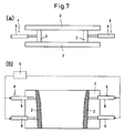
- FIG. 7 is a view showing a continuous casting mold of the present invention, in which (a) is a plan view and (b) is a sectional front view.
- FIG. 8 is a diagram showing a solidified shell shape at the lower end of the mold obtained by calculation.
- the present invention reduces the taper change point position from the meniscus as the maximum casting speed becomes faster, and thus in a wide casting width range from narrow to wide. Both the solidification uniformity and the restraining force can be maintained in a favorable range.
- the maximum casting speed for casting is V M (m / min), and the distance from the meniscus position of the multistage tapered short side mold plate to the first taper changing point in the casting direction is the changing point position x (mm). .
- the total taper rate T T , the upper taper rate T U , the lower taper rate T L , and the vertical taper ratio are defined as follows.
- W in the lower tapered face 6 L of the casting direction lowermost multistage tapered short side mold plate optionally define the upper and lower positions, the distance between both short sides, W 3 in the upper position (m), in the lower position 4 (m), when the distance from the upper position to the lower position is set to ⁇ L (m) (FIGS.
- JP 2006-346735 A and JP 2006-34636 A describe a method of estimating the solidification behavior of a slab in a mold by calculation. When the slope of the casting or the casting speed is set to an arbitrary value, the thickness of the solidified shell at each part around the four sides of the mold is calculated as shown in FIG.
- the ratio B / A between the maximum value A and the minimum value B of the solidified shell thickness at the lower end of the mold, the binding force between the solidified shell and the mold, and the gap amount can be obtained.
- the shape of the solidified shell at the lower end of the mold and the binding force between the solidified shell and the mold were determined for continuous casting using a multistage tapered short side mold plate.
- the shape of the solidified shell at the lower end of the mold is derived as shown in FIG. 8 by calculation.
- a portion with a thin solidified shell thickness may be formed on the long side of the solidified shell in the vicinity of the slab corner, and the solidified shell thickness at this portion can be set to the minimum value B of the shell thickness.
- the ratio B / A between the maximum value A and the minimum value B of the solidified shell thickness is referred to herein as “solidification uniformity”.
- solidification uniformity The ratio B / A between the maximum value A and the minimum value B of the solidified shell thickness.
- the calculation method of the present invention solidification uniformity and binding force.
- the distance L from the meniscus position to the lower end of the mold is about 900 mm
- the change point position x is about 300 mm.
- the casting width is 1100 mm (narrow), the total taper rate is 1.6% / m, the changing point position x of the two-step taper short side mold plate is constant 300 mm, and the casting speed is 1.0 to 3.0 m / min.
- the bending condition of the short side mold plate was changed by changing the vertical taper ratio of the two-step taper short side mold plate, and the solidification uniformity and the binding force were calculated by the calculation method of the present invention. As shown in FIG. 2, if the taper ratio is the same, the solidification uniformity improves as the casting speed increases, but the binding force also increases.
- the upper and lower taper ratio preferable range is 5.0 or less and the casting speed is 2 at a casting speed of 2.0 m / min.
- the preferable range of the upper and lower taper ratio was 4.0 or less at 0.5 m / min, and the preferable range of the upper and lower taper ratio was 3.0 or less at the casting speed of 3.0 m / min.
- the shape of a short side mold plate having a casting width of 1100 mm and good solidification uniformity and restraining force (a mold shape having an up / down taper ratio of 3.0 optimized for a casting speed in the range of 3.0 m / min)
- the casting width was as wide as 2200 mm.
- the total taper ratio was kept at 1.6% / m.
- the width was 2200 mm and the up / down taper ratio was 1.7.
- the casting speed was 3.0 m / in when the slab width was widened while keeping the total taper constant.
- the preferred range of the vertical taper ratio was reduced to less than 1.7 and the solidification uniformity was also reduced (FIG. 3). That is, it was found that in a mold optimized for high-speed casting up to a casting speed of 3.0 m / min at a width of 1100 mm, if the casting width was 2200 mm, it was out of the optimum range. Therefore, when the multi-step taper is optimized for each casting speed in the width of 1100 mm, the change is not made by fixing the change point position x and changing the vertical taper ratio but by keeping the vertical taper ratio constant at 4.0. I tried changing the point position x.
- the total taper rate was 1.6% / m
- the change point position x was changed, and the solidification uniformity and the binding force were calculated by the calculation method of the present invention.
- the result is shown in FIG.
- the change point position preferred range was 300 mm or less
- the change point position preferred range was 200 mm or less.
- the vertical taper ratio was 2.5 at the cast width of 2200 mm. Therefore, in the 2200 mm width, the total taper rate is set to 1.6% / m, and the vertical taper ratio is kept constant at 2.5 as described above, and the change point position x is changed by the calculation method of the present invention.
- the calculation result of solidification uniformity and binding force is shown (FIG. 5). As is apparent from FIG. 5, it was found that if the change point position x is 200 mm or less, a good range can be secured at a casting speed of 3.0 m / min or less even if the casting width is 2200 mm.
- the change point position x when comparing the upper and lower taper ratio at the time of narrow width with a suitable upper limit taper ratio when applied at the time of wide width using a mold optimized by changing the vertical ratio for each casting speed, the change point position x
- a mold optimized by changing the width it is possible to increase the preferred vertical taper ratio, and when the change point x is changed, the width is wider than the narrow width.
- the coagulation uniformity increased conversely although the preferred vertical taper ratio decreased. That is, when determining the optimum taper shape of the multi-stage tapered short side mold plate when the casting speed becomes high, as shown in FIGS. 4 and 5, the change point position x is raised upward as the casting speed becomes higher.
- V M is a solution eliminates exceeds 3.75 m / min. That is, the upper limit of V M in the present invention is 3.75 m / min.
- the upper limit of x is set to 300 mm because when the upper and lower taper ratio is to be secured above a certain value, when the upper strong taper region becomes longer, the taper rate of the lower taper portion becomes smaller and the total taper rate is constant and the width is increased. This is because when the width is reduced and the casting is narrow, the lower taper ratio becomes extremely small, and it tends to become a reverse taper (expands as the taper goes down), which easily causes trouble that the slab bulges at the bottom of the mold. .
- the effect is remarkable as the maximum casting speed V M is increased. Maximum casting speed V M can exhibit particularly remarkable effects in the high-speed casting of 2.5 m / min greater.
- the casting speed is fixed at 1.5 m / min
- the casting width is fixed at 1100 mm
- the total taper ratio is changed to solidify.
- Uniformity and binding force were calculated.
- the slab thickness was 240 mm. The results are shown in FIG. As is clear from the figure, the solidification uniformity can be maintained well if the total taper rate is 0.5% / m or more. Further, if the total taper rate is 2.0% / m or less, the restraining force is small, and it can be held well.
- the multi-stage tapered short side mold plate used in the present invention a mold plate having a taper of three or more stages may be used, but as a result of setting the change point position upward, the two-stage tapered short side mold plate is sufficient.
- the cast slab thickness is preferably 220 mm to 300 mm, more preferably 240 mm to 300 mm.
- the slab thickness exceeds 300 mm, excessive equipment is required as a continuous casting mold for changing the width during casting, which is substantially difficult to realize. If the casting thickness is less than 240 mm, the diameter of the immersion nozzle for injecting the molten metal from the tundish must be reduced, so that uniform injection of the molten metal becomes difficult.
- the continuous casting mold 1 of the present invention includes a long-side mold plate 3 and a multistage tapered short-side mold plate 2 having two or more short-side taper ratios (unit:% / m) different in the casting direction.
- the long-side mold plate 3 and the short-side mold plate 2 are each composed of a pair, and the side facing the solidified shell is preferably a water-cooled copper plate, and the opposite surface is a steel back frame.
- the width of the short side mold plate 2 is substantially equal to the thickness of the cast piece to be cast.
- the continuous casting mold 1 of the present invention further includes a short side driving device 4 that can change the width of the cast slab and the inclination of the short side, and a control device 5 for the short side driving device.
- the taper ratio at the uppermost short side in the casting direction is the upper taper ratio
- the taper ratio at the lowermost side is the lower taper ratio
- the taper ratio at the short side surface connecting the meniscus part and the lower end of the mold with a straight line is the total taper ratio.
- the value obtained by dividing the upper taper rate by the lower taper rate is defined as the upper and lower taper ratio, which is the same as in the continuous casting method of the present invention.
- the control device 5 of the short side drive device drives the short side mold plate so that the same total taper ratio is obtained in any slab width during casting, and the vertical taper ratio is 4 or less in any slab width. Control is preferable as a practical operation mode.
- the short-side drive device 4 has, for example, two upper and lower drive actuators 9 and holds the short-side mold plate 2 by the actuator 9 from the back frame side. By determining the position of the short-side mold plate by the movement of the upper and lower actuators 9, the total taper ratio of the short-side mold plate 2 can be set to a predetermined value for each casting width.
- an electric cylinder, a hydraulic cylinder, or the like can be used. Or it is good also as an apparatus which has a drive means which performs a reciprocating motion and a swing motion of a short side mold plate as a short side drive device.
- the continuous casting mold of the present invention is preferable because the minimum castable slab width is 1100 mm or less and the maximum castable slab width is 2200 mm or more, because a slab having a wide range can be cast. .
- the minimum castable slab width is preferably 800 mm or less.
- the minimum castable slab width is practically 600 mm.
- the maximum castable slab width is realistic 2500 mm.
- the solidification level is reduced in a wide casting width range from narrow to wide by shortening the taper change point position from the meniscus as the maximum casting speed increases. It is possible to maintain the binding force in a good range once.
Landscapes
- Engineering & Computer Science (AREA)
- Mechanical Engineering (AREA)
- Continuous Casting (AREA)
Priority Applications (4)
| Application Number | Priority Date | Filing Date | Title |
|---|---|---|---|
| BRPI0924937-0A BRPI0924937B1 (pt) | 2009-03-19 | 2009-03-19 | Method of continuous casting, laterally narrow molding plate, and mold for continuous casting |
| PCT/JP2009/056215 WO2010106696A1 (ja) | 2009-03-19 | 2009-03-19 | 連続鋳造方法及び連続鋳造鋳型 |
| CN200980158156.XA CN102355964B (zh) | 2009-03-19 | 2009-03-19 | 连铸方法、连铸用的短边铸模板和连铸铸模 |
| KR1020117019262A KR20110103474A (ko) | 2009-03-19 | 2009-03-19 | 연속 주조 방법 및 연속 주조 주형 |
Applications Claiming Priority (1)
| Application Number | Priority Date | Filing Date | Title |
|---|---|---|---|
| PCT/JP2009/056215 WO2010106696A1 (ja) | 2009-03-19 | 2009-03-19 | 連続鋳造方法及び連続鋳造鋳型 |
Publications (1)
| Publication Number | Publication Date |
|---|---|
| WO2010106696A1 true WO2010106696A1 (ja) | 2010-09-23 |
Family
ID=42739362
Family Applications (1)
| Application Number | Title | Priority Date | Filing Date |
|---|---|---|---|
| PCT/JP2009/056215 WO2010106696A1 (ja) | 2009-03-19 | 2009-03-19 | 連続鋳造方法及び連続鋳造鋳型 |
Country Status (4)
| Country | Link |
|---|---|
| KR (1) | KR20110103474A (zh) |
| CN (1) | CN102355964B (zh) |
| BR (1) | BRPI0924937B1 (zh) |
| WO (1) | WO2010106696A1 (zh) |
Cited By (1)
| Publication number | Priority date | Publication date | Assignee | Title |
|---|---|---|---|---|
| JP2013220443A (ja) * | 2012-04-17 | 2013-10-28 | Nippon Steel & Sumitomo Metal Corp | 連続鋳造用鋳型およびこれを用いた鋼の連続鋳造方法 |
Citations (1)
| Publication number | Priority date | Publication date | Assignee | Title |
|---|---|---|---|---|
| JP2007175769A (ja) * | 2005-11-30 | 2007-07-12 | Kobe Steel Ltd | 連続鋳造方法 |
Family Cites Families (8)
| Publication number | Priority date | Publication date | Assignee | Title |
|---|---|---|---|---|
| US4306610A (en) * | 1979-10-03 | 1981-12-22 | Korf Technologies, Inc. | Method of controlling continuous casting rate |
| ATE105750T1 (de) * | 1991-02-06 | 1994-06-15 | Concast Standard Ag | Kokille zum stranggiessen von metallen, insbesondere von stahl. |
| CN2250210Y (zh) * | 1996-01-24 | 1997-03-26 | 章仲禹 | 水平连铸高效耐磨结晶器铜套 |
| CN2288798Y (zh) * | 1996-10-25 | 1998-08-26 | 冶金工业部北京冶金设备研究院 | 管式连铸结晶器 |
| KR100376504B1 (ko) * | 1998-08-04 | 2004-12-14 | 주식회사 포스코 | 연속주조방법및이에이용되는연속주조장치 |
| US7493936B2 (en) * | 2005-11-30 | 2009-02-24 | Kobe Steel, Ltd. | Continuous casting method |
| JP5047714B2 (ja) * | 2007-07-18 | 2012-10-10 | 新日本製鐵株式会社 | 連続鋳造方法及び連続鋳造鋳型 |
| JP4608558B2 (ja) * | 2008-01-10 | 2011-01-12 | 新日本製鐵株式会社 | 連続鋳造方法及び連続鋳造鋳型 |
-
2009
- 2009-03-19 BR BRPI0924937-0A patent/BRPI0924937B1/pt active IP Right Grant
- 2009-03-19 KR KR1020117019262A patent/KR20110103474A/ko active Search and Examination
- 2009-03-19 WO PCT/JP2009/056215 patent/WO2010106696A1/ja active Application Filing
- 2009-03-19 CN CN200980158156.XA patent/CN102355964B/zh active Active
Patent Citations (1)
| Publication number | Priority date | Publication date | Assignee | Title |
|---|---|---|---|---|
| JP2007175769A (ja) * | 2005-11-30 | 2007-07-12 | Kobe Steel Ltd | 連続鋳造方法 |
Cited By (1)
| Publication number | Priority date | Publication date | Assignee | Title |
|---|---|---|---|---|
| JP2013220443A (ja) * | 2012-04-17 | 2013-10-28 | Nippon Steel & Sumitomo Metal Corp | 連続鋳造用鋳型およびこれを用いた鋼の連続鋳造方法 |
Also Published As
| Publication number | Publication date |
|---|---|
| CN102355964A (zh) | 2012-02-15 |
| BRPI0924937B1 (pt) | 2017-07-18 |
| CN102355964B (zh) | 2014-02-19 |
| KR20110103474A (ko) | 2011-09-20 |
Similar Documents
| Publication | Publication Date | Title |
|---|---|---|
| JP5047714B2 (ja) | 連続鋳造方法及び連続鋳造鋳型 | |
| JP4608558B2 (ja) | 連続鋳造方法及び連続鋳造鋳型 | |
| KR101941506B1 (ko) | 연속 주조용 주형 및 강의 연속 주조 방법 | |
| RU2547775C2 (ru) | Устройство и способ непрерывного литья | |
| JP5428902B2 (ja) | 連続鋳造方法及び連続鋳造装置 | |
| WO2010106696A1 (ja) | 連続鋳造方法及び連続鋳造鋳型 | |
| KR101149370B1 (ko) | 연속주조기용 세그먼트 | |
| JP5825084B2 (ja) | 高炭素鋼スラブの連続鋳造方法 | |
| JP4337565B2 (ja) | 鋼のスラブ連続鋳造方法 | |
| JP5042785B2 (ja) | 連続鋳造用鋳型の短辺テーパー制御方法 | |
| JP2016022521A (ja) | 連続鋳造用鋳型装置 | |
| JP2964560B2 (ja) | 垂直連続鋳造装置 | |
| CN114734007B (zh) | 一种高牌号硅钢连铸坯窄侧鼓肚控制方法 | |
| JP5423434B2 (ja) | 連続鋳造方法及び連続鋳造装置 | |
| JP4836303B2 (ja) | 連続鋳造鋳型 | |
| JP6743872B2 (ja) | 連続鋳造時の鋳片幅の拡大方法 | |
| US20090178777A1 (en) | Casting machine for production of casting bars in the shape of billets or blocks | |
| KR101435034B1 (ko) | 후판 압연 제어 방법 | |
| KR100840284B1 (ko) | 연속주조설비의 더미바 | |
| JP2022065814A (ja) | 連続鋳造用鋳型及び鋼の連続鋳造方法 | |
| JP3020538B2 (ja) | 連続鋳造時における幅拡大方法 | |
| KR101969112B1 (ko) | 주형 | |
| JP3601591B2 (ja) | 内部割れの少ない鋼の連続鋳造方法 | |
| JPH10249492A (ja) | 鋼の連続鋳造用鋳型 | |
| JPH08257715A (ja) | 連続鋳造方法 |
Legal Events
| Date | Code | Title | Description |
|---|---|---|---|
| WWE | Wipo information: entry into national phase |
Ref document number: 200980158156.X Country of ref document: CN |
|
| 121 | Ep: the epo has been informed by wipo that ep was designated in this application |
Ref document number: 09841898 Country of ref document: EP Kind code of ref document: A1 |
|
| ENP | Entry into the national phase |
Ref document number: 20117019262 Country of ref document: KR Kind code of ref document: A |
|
| WWE | Wipo information: entry into national phase |
Ref document number: 6386/CHENP/2011 Country of ref document: IN |
|
| NENP | Non-entry into the national phase |
Ref country code: DE |
|
| 122 | Ep: pct application non-entry in european phase |
Ref document number: 09841898 Country of ref document: EP Kind code of ref document: A1 |
|
| NENP | Non-entry into the national phase |
Ref country code: JP |
|
| REG | Reference to national code |
Ref country code: BR Ref legal event code: B01A Ref document number: PI0924937 Country of ref document: BR |
|
| ENP | Entry into the national phase |
Ref document number: PI0924937 Country of ref document: BR Kind code of ref document: A2 Effective date: 20110919 |