WO2010106627A1 - 画像処理装置、画像処理方法、画像処理プログラム、および、監視装置 - Google Patents
画像処理装置、画像処理方法、画像処理プログラム、および、監視装置 Download PDFInfo
- Publication number
- WO2010106627A1 WO2010106627A1 PCT/JP2009/055081 JP2009055081W WO2010106627A1 WO 2010106627 A1 WO2010106627 A1 WO 2010106627A1 JP 2009055081 W JP2009055081 W JP 2009055081W WO 2010106627 A1 WO2010106627 A1 WO 2010106627A1
- Authority
- WO
- WIPO (PCT)
- Prior art keywords
- cover
- image
- plate
- image processing
- color
- Prior art date
- Legal status (The legal status is an assumption and is not a legal conclusion. Google has not performed a legal analysis and makes no representation as to the accuracy of the status listed.)
- Ceased
Links
Images






Classifications
-
- G—PHYSICS
- G08—SIGNALLING
- G08G—TRAFFIC CONTROL SYSTEMS
- G08G1/00—Traffic control systems for road vehicles
- G08G1/01—Detecting movement of traffic to be counted or controlled
- G08G1/017—Detecting movement of traffic to be counted or controlled identifying vehicles
- G08G1/0175—Detecting movement of traffic to be counted or controlled identifying vehicles by photographing vehicles, e.g. when violating traffic rules
-
- G—PHYSICS
- G06—COMPUTING OR CALCULATING; COUNTING
- G06V—IMAGE OR VIDEO RECOGNITION OR UNDERSTANDING
- G06V20/00—Scenes; Scene-specific elements
- G06V20/60—Type of objects
- G06V20/62—Text, e.g. of license plates, overlay texts or captions on TV images
- G06V20/63—Scene text, e.g. street names
-
- G—PHYSICS
- G06—COMPUTING OR CALCULATING; COUNTING
- G06V—IMAGE OR VIDEO RECOGNITION OR UNDERSTANDING
- G06V40/00—Recognition of biometric, human-related or animal-related patterns in image or video data
- G06V40/40—Spoof detection, e.g. liveness detection
-
- G—PHYSICS
- G06—COMPUTING OR CALCULATING; COUNTING
- G06V—IMAGE OR VIDEO RECOGNITION OR UNDERSTANDING
- G06V20/00—Scenes; Scene-specific elements
- G06V20/60—Type of objects
- G06V20/62—Text, e.g. of license plates, overlay texts or captions on TV images
- G06V20/625—License plates
Definitions
- This case relates to an automobile registration number mark image processing apparatus, an image processing method thereof, an image processing program thereof, and an automobile registration number mark monitoring apparatus.
- plate reading systems that automatically read automobile registration numbers (number plates, hereinafter also referred to as plates) of automobiles (including motorcycles and motorbikes) on roads and parking lots have become widespread.
- Many types of plate reading systems employ near-infrared cameras that have sensitivity in the near-infrared region.
- a license plate cover (hereinafter also referred to as a cover) for disturbing reading by a plate reading system is in circulation.
- a cover includes a type manufactured so that the transmittance in the near-infrared region is lower than that in the visible light region.
- the present invention aims to provide a technique for detecting whether or not a cover is attached to a plate.
- the disclosed monitoring apparatus employs the following means in order to solve the above-described problems.
- the disclosed aspect is: An image processing apparatus for determining whether a cover is attached to a license plate, From a color photographed image of the surface of the license plate, a calculation unit that calculates a color feature amount of a predetermined region in the surface; If the color feature amount indicates a color when a cover is not attached, it is determined that a cover is not attached to the surface of the license plate. Otherwise, a cover is attached to the surface of the license plate.
- the image processing apparatus includes a determination unit that determines that it is attached.
- FIG. 1 is a diagram showing an example of the transmittance of a license plate cover having a low transmittance in the near infrared region.
- FIG. 2 is a diagram illustrating an example of a monitoring system.
- FIG. 3 is a diagram illustrating an example of functional blocks of the image processing apparatus.
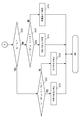
- FIG. 4 is a diagram illustrating an example of an overall operation flow of the image processing apparatus.
- FIG. 5 is a diagram illustrating an example of an image of the extracted plate portion.
- FIG. 6 is a diagram illustrating an example of a mask image.
- FIG. 7 is a diagram illustrating an example of information stored in the storage unit.
- FIG. 1 is a diagram showing an example of the transmittance of a license plate cover having a low transmittance in the near infrared region.
- FIG. 2 is a diagram illustrating an example of a monitoring system.
- FIG. 3 is a diagram illustrating an example of functional blocks of the image processing apparatus.
- FIG. 4 is a diagram
- FIG. 8 is a diagram illustrating a specific example (1) of the operation flow of the calculation unit of the cover identification unit when determining which of the character part and the background part is used for determination is made. is there.
- FIG. 9 is a diagram illustrating a specific example (2) of the operation flow of the calculating unit of the cover identifying unit when determining which of the character part and the background part is used for determination is made. is there.
- FIG. 10 is a diagram illustrating an example of an operation flow of the calculation unit 221 of the cover identification unit 220 when calculating the average value and color feature amount of the R component, G component, and B component of the background portion of the image of the plate portion. is there.
- FIG. 11 is a diagram illustrating a specific example of the condition of the color feature amount that determines that the cover is not attached to the plate.
- FIG. 12 is a diagram illustrating an example of a determination operation flow of the determination unit 222 of the cover identification unit.
- FIG. 13 is a diagram showing, on the coordinate plane, the condition of the color feature amount determined that the cover is not attached.
- FIG. 1 is a diagram showing an example of the transmittance of a license plate cover having a low transmittance in the near infrared region.
- the horizontal axis of the coordinate plane in FIG. 1 is the wavelength, and the vertical axis is the transmittance.
- the transmittance in the visible light region of a license plate cover (hereinafter also referred to as a cover) having a low transmittance in the near infrared region varies depending on the wavelength of light. Therefore, when a plate with a cover is photographed with a color camera that shoots in the visible light region, the color of the plate on the photographed image is different from the color when the plate is photographed without the cover attached. Taken at. Therefore, it is determined whether or not the cover is attached to the plate by checking whether or not the color of the plate on the image taken with the color camera is the original plate color (color when the cover is not attached). be able to. It is assumed that the color of the plate when the cover is not attached is known.
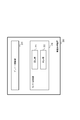
- FIG. 2 is a diagram illustrating an example of an embodiment of the monitoring system.
- the monitoring system 10 in FIG. 2 includes an imaging device 100 and an image processing device 200.
- the monitoring system 10 may be a monitoring device including the imaging device 100 and the image processing device 200.
- the imaging device 100 includes a color camera 1A, an illumination device 1B, and an image data generation circuit 1C.
- the color camera 1A is installed at a position where the plate P can be satisfactorily photographed on a road, a parking lot, or the like where the automobile C with the plate P is traveling.
- the color camera 1A has sensitivity at least in the visible light region.
- the color camera 1A may be a still camera that shoots a still image or a video camera that shoots a moving image (video).
- a video camera is applied as the color camera 1A.
- the color camera 1A performs video shooting. Video shooting is performed, for example, at 30 frames per second. A video signal (video data) in a predetermined signal format obtained by photographing with the color camera 1A is sent to the image data generation circuit 1C.
- the lighting device 1B illuminates the subject (plate P) in conjunction with the shooting operation of the color camera 1A in order to obtain a good shot image with the color camera 1A.
- a light is applied as the illumination device 1B.
- a strobe may be applied to capture a still image.
- the image data generation circuit 1C is connected to the color camera 1A and receives a video signal from the color camera 1A.
- the image data generation circuit 1C generates image data having a predetermined format from the video signal.
- image data for example, image data having RGB (Red Green Blue) for each pixel, that is, a color image in RGB (Red Green Blue) format is generated.
- RGB red component
- G component green component
- B component blue component
- YUV YUV Parameters according to the color system
- the image data generated by the image data generation circuit 1C is sent to the image processing apparatus 200 via a signal line.
- the image data includes information on the date and time taken by the color camera 1A.
- the image processing apparatus 200 includes a CPU (Central Processing Unit) 2A, a memory 2B, a storage unit 2C, and an IF (Interface) 2D.
- a CPU Central Processing Unit
- memory 2B a memory 2B
- storage unit 2C a storage unit 2C
- IF Interface
- the CPU 2A performs processing according to the program in the storage unit 2C.
- the CPU 2A caches programs and data and develops a work area.
- the storage unit 2C records various programs and various data on a recording medium in a readable and writable manner.
- the storage unit 2C there is a solid state drive device, a hard disk drive device, a DVD (Digital Versatile Disk) drive device, a + R / + RW drive device, or a BD (Blu-ray Disk) drive device.
- the recording medium there are a silicon disk including a nonvolatile semiconductor memory (flash memory), a hard disk, a DVD, + R / + RW, or a BD. DVDs include DVD-R (Recordable) and DVD-RAM (Random Access Memory).
- the BD there are a BD-R, a BD-RE (Rewritable), and a BD-ROM.
- the storage unit 2C may be an external storage device connected to the image processing apparatus 200 via a network.
- IF2D exchanges data with external devices.
- IF2D is connected to imaging device 100 via a signal line.
- FIG. 3 is a diagram illustrating an example of functional blocks of the image processing apparatus.
- the image processing apparatus 200 includes a plate recognition unit 210 and a cover identification unit 220.
- the cover identification unit 220 includes a calculation unit 221 and a determination unit 222.
- the plate recognition unit 210 and the cover identification unit 220 may be realized by a program executed by the image processing apparatus 200.
- the plate recognition unit 210 is realized by cooperation of hardware such as the CPU 2A and a program stored in the storage unit 2C.
- the cover identification unit 220 is realized by cooperation of hardware such as the CPU 2A and a program stored in the storage unit 2C.
- the plate recognition unit 210 extracts an image of the plate portion from the image data received from the imaging device 100.
- the plate recognition unit 210 separates the extracted plate portion into a character portion and a background portion.
- the plate recognition unit 210 reads characters in the character portion of the image of the plate portion.
- the cover identification unit 220 includes a calculation unit 221 and a determination unit 222.
- the calculation unit 221 of the cover identification unit 220 calculates a color feature amount from the image of the plate portion.
- the determination unit 222 of the cover identification unit 220 determines whether or not a cover is attached to the plate.
- the determination unit 222 of the cover identification unit 220 can perform determination using the luminance of the character portion or the color feature amount of the background portion in the image of the plate portion of the photographed image.
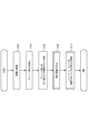
- FIG. 4 is a diagram showing an example of the overall operation flow of the image processing apparatus.
- the plate recognition unit 210 of the image processing device 200 receives image data from the imaging device 100 every predetermined time (S102).
- the plate recognition unit 210 of the image processing device 200 extracts an image of the plate portion from the image data received from the imaging device 100 (S104). Any method may be used as a method for extracting the image of the plate portion. For example, a method described in Non-Patent Document 1 may be used as a method for extracting an image of a plate portion. When the plate recognition unit 210 cannot extract the image of the plate portion from the image data received from the imaging device 100, the plate recognition unit 210 discards the image data and extracts the image of the plate portion for the next received image.
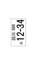
- FIG. 5 is a diagram showing an example of the extracted image of the plate portion.
- the plate recognition unit 210 of the image processing apparatus 200 can extract the image of the plate portion from the image data received from the imaging apparatus 100 as shown in FIG.
- the plate recognition unit 210 of the image processing apparatus 200 separates the extracted image of the plate portion into a character portion and a background portion (S106). Any method may be used as a method for separating the extracted image of the plate portion into the character portion and the background portion. As a method for separating the extracted image of the plate portion into the character portion and the background portion, for example, a method described in Non-Patent Document 1 may be used.
- the plate recognition unit 210 generates information indicating the character part area. For example, the plate recognition unit 210 may generate an image (hereinafter also referred to as a mask image) in which the pixel value of the background portion is 0 and the pixel value of the character portion is 1 as information indicating the character portion area. it can.
- the mask image is an image that clearly shows the area of the character part in the image of the plate part.
- the mask image is the same size as the image of the plate portion. The same coordinates are used for the mask image and the image of the plate portion.
- the plate recognizing unit 210 may generate information indicating the character part area by another method without using the mask image.
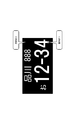
- FIG. 6 is a diagram showing an example of a mask image.
- the background portion is displayed in black and the character portion is displayed in white.
- the plate recognition unit 210 of the image processing apparatus 200 can generate a mask image in which the pixel value of the background portion is 0 and the pixel value of the character portion is 1.
- the plate recognition unit 210 of the image processing apparatus 200 reads character information from the character part of the image of the plate part, and stores information on the read character such as the character, the character position, and the character size in the storage unit 2C. Any method may be used as a method by which the plate recognition unit 210 reads character information from the character portion of the image of the plate portion.
- the character portion of the image of the plate portion is mainly an automobile registration number.
- the plate recognizing unit 210 associates the date and time when the image received from the image capturing apparatus 100 was captured with information related to the read character, and stores them in the storage unit 2C.
- the calculating unit 221 of the cover identifying unit 220 of the image processing apparatus 200 determines to perform determination using the color feature amount of the character part or the background part from the image of the plate part extracted by the plate recognizing unit 210.
- the color feature amount of the portion thus obtained is calculated (S108). The operation of the calculation unit 221 will be described later.
- the cover identification unit 220 of the image processing apparatus 200 determines whether or not the cover is attached to the plate from the information indicating the area of the character part (S110).
- the determination unit 222 of the cover identification unit 220 determines whether or not a cover is attached to the plate.
- the determination unit 222 of the cover identification unit 220 associates the determination result with the date and time when the original image of the plate part used for the determination was captured and the characters that the plate recognition unit 210 read from the image of the plate part. And stored in the storage unit 2C. The operation of the determination unit 222 will be described later.
- FIG. 7 is a diagram illustrating an example of information stored in the storage unit.
- the storage unit 2C covers the date and time when the image received from the imaging device 100 was captured, the characters read by the plate recognition unit 210 from the image of the plate portion, and the plate determined by the determination unit 222 of the cover identification unit 220. Is stored in association with each other. By storing these pieces of information in association with each other, the automobile that has the cover attached to the plate and the date and time thereof are specified.
- FIG. 8 and FIG. 9 are diagrams illustrating a specific example of the operation flow of the calculation unit of the cover identification unit when determining which of the character part and the background part to use for determining the color feature amount. is there. “A” in FIG. 8 is connected to “A” in FIG.
- the calculation unit 221 of the cover identification unit 220 obtains the average value of the luminance of the character part and the background part of the image of the plate part, and uses which color feature amount to determine whether or not the cover is attached. decide. It is difficult to correctly determine the color of the plate in a portion where the luminance of the image is low.
- the calculation unit 221 compares the average luminance values of the character portion and the background portion, and determines to determine the higher luminance average value.
- the calculation unit 221 initializes variables to be used (FIG. 8: S202).
- the calculation unit 221 substitutes the value 0 for the number of pixels Nc of the character portion in the image of the plate portion and the integrated value Sc of the luminance of the character portion of the image of the plate portion. Further, the calculation unit 221 substitutes a value of 0 for the number of pixels Nb of the background portion in the plate portion image and the integrated value Sb of the luminance of the background portion in the plate portion image.
- the calculation unit 221 confirms whether all the pixels of the image of the plate portion have been processed (S204).
- the calculation unit 221 selects the coordinates (i, j) of unprocessed pixels when all the pixels are not processed among the pixels of the image of the plate portion (S204; NO) (S206).
- the calculation unit 221 can store the coordinates (i, j) of the processed pixel among the pixels of the image of the plate portion.
- the calculation unit 221 confirms whether or not the coordinates (i, j) of the image of the plate part are the character part based on the information indicating the position of the character part such as the mask image (S208).
- the calculation unit 221 adds a value 1 to the number of pixels Nc of the character part.
- the calculation unit 221 adds the value of the green component (G component) of the coordinates (i, j) of the image of the plate portion as the luminance value to the integrated value Sc of the luminance of the character portion (S210).
- the calculation unit 221 adds the value 1 to the number of pixels Nb in the background part. Further, the calculation unit 221 adds the value of the green component (G component) of the coordinates (i, j) of the image of the plate portion as the luminance value to the integrated luminance value Sb of the background portion (S212).
- the green component is used as the luminance value, but other values may be used.
- the sum of a red component, a green component, and a blue component may be used as the luminance value.
- the calculation unit 221 confirms again whether all the pixels among the pixels of the image of the plate portion have been processed after the processing of step S210 or step S212 (S204).
- the calculation unit 221 substitutes Sb / Nb for the average luminance value Ib of the background portion, and calculates the average luminance value of the character portion. Sc / Nc is substituted for Ic (S220).
- the calculating unit 221 compares the average luminance value Ib of the background portion of the plate portion image with the average luminance value Ic of the character portion of the plate portion image (FIG. 9: S222).
- the calculation unit 221 checks whether the average value Ib is greater than the first threshold Th1 or whether the average value Ib is less than the second threshold Th2 ( S224).
- the average value Ib being larger than the first threshold Th1 means that the background portion of the image of the plate portion is very bright. If the background portion of the plate portion image is very bright, it is difficult to determine the color of the background portion of the plate portion image.
- the average value Ib being smaller than the second threshold Th2 means that the background portion of the image of the plate portion is very dark. If the background portion of the plate portion image is very dark, it is difficult to determine the color of the background portion of the plate portion image.
- the calculation unit 221 is unclear whether or not the cover is attached to the plate. Determination is made (S226).
- the calculating unit 221 determines whether or not the cover is attached using the color feature amount of the background portion. Is determined (S228).
- the first threshold Th1 is larger than the second threshold Th2.
- the calculation unit 221 checks whether the average value Ic is larger than the first threshold Th1 or whether the average value Ic is smaller than the second threshold Th2 ( S230). When the average value Ic is larger than the first threshold value or smaller than the second threshold value (S230; YES), it is determined whether it is unknown whether or not the cover is attached to the plate (S232). When the average value Ic is equal to or less than the first threshold value and the average value Ic is equal to or greater than the second threshold value (S230; NO), the calculation unit 221 determines whether or not the cover is attached using the color feature amount of the character portion. Is determined (S234).
- the calculation unit 221 determines that it is unknown whether or not the cover is attached to the plate (S226 and S232)
- the calculation unit 221 stores the fact that it is unknown in the storage unit 2C.
- the calculation unit 221 stores the fact that it is unknown in the storage unit 2C in association with the date and time when the original image of the plate portion was captured and the characters read from the plate portion image.
- FIG. 10 is a diagram illustrating an example of an operation flow of the calculation unit 221 of the cover identification unit 220 when calculating the average value and color feature amount of the R component, G component, and B component of the background portion of the image of the plate portion. is there.
- the R component, G component, and B component of the character part of the image of the plate part are performed in the same operation flow.
- An average value is obtained.
- required here is used when determining whether the cover is mounted
- the calculation unit 221 uses the color feature amount to determine a portion for determining whether or not the cover is mounted, and then calculates an average value and a color feature amount for the portion.
- the calculation unit 221 obtains the luminance value of each color (red, green, and blue) in the background portion area on the plate portion image from the information indicating the plate portion image and the character portion area.
- the average values of the red, green, and blue luminance values in the region of the background portion on the image of the plate portion are Ar, Ag, and Ab, respectively.
- the calculation unit 221 initializes variables to be used (S302).
- the calculation unit 221 substitutes a value of 0 for the number N of pixels in the background portion of the plate portion image. Further, the calculation unit 221 calculates the value of the integrated value R of the red component (R component) of the background portion, the integrated value G of the green component (G component), and the integrated value B of the blue component (B component) in the image of the plate portion. Substitute 0.
- the calculation unit 221 confirms whether or not all the pixels in the image of the plate portion have been processed (S304).
- the calculation unit 221 selects coordinates (i, j) of unprocessed pixels when not processing all the pixels among the pixels of the image of the plate portion (S304; NO) (S306).
- the calculation unit 221 confirms whether or not the coordinates (i, j) of the image of the plate portion are the background portion based on information indicating the position of the character portion such as a mask image (S308).
- the coordinate (i, j) is a character part (S308; NO)
- the calculation unit 221 confirms again whether all the pixels of the pixels of the image of the plate part have been processed (S304).
- the coordinates (i, j) are the background part (S308; YES)
- the calculation unit 221 adds 1 to the number N of pixels in the background part.
- the calculation unit 221 adds the values of the red component, the green component, and the blue component of the coordinates (i, j) of the image of the plate portion to the integrated value R, the integrated value G, and the integrated value B, respectively. (S310).
- step S310 the calculation unit 221 checks again whether all the pixels of the image of the plate portion have been processed (S304).
- the calculation unit 221 When all of the pixels in the image of the plate portion are processed (S304; YES), the calculation unit 221 performs R / N for the average luminance value Ar of the red component and G for the average luminance value Ag of the green component. / N and B / N are substituted into the average luminance value Ab of the blue component (S320).
- the calculation unit 221 calculates a color feature amount from the average values Ar, Ag, and Ab (S322).
- a color feature amount for example, a ratio Ar / Ag of the red luminance value Ar to the green luminance value Ag and a ratio Ab / Ag of the blue luminance value Ab to the green luminance value Ag are used. Further, a green luminance value Ag is used as a luminance value representative of the background portion area.
- the color feature amount is defined as a ratio to the green luminance value.
- the human eye has sensitivity in a visible light region, a region near red, a region near green, and a region near blue. Among these, since the red wavelength and the green wavelength are close to each other, the color change with respect to the wavelength change is large between the green region and the red region. If the color feature amount is defined as a ratio to the green luminance value, the color change can be easily identified. Even when the overall luminance value of the image is lowered due to a decrease in the amount of illumination light around the camera where the image is taken, the color feature amount of the image does not change greatly. Therefore, the cover identifying unit 220 does not need to change the determination condition as to whether or not the cover is attached by increasing or decreasing the amount of illumination light around the camera.
- the color feature amount calculated here is used by the determination unit 222 of the cover identification unit 220 when determining whether or not the cover is attached to the plate.
- FIG. 11 is a diagram showing a specific example of the condition of the color feature amount that determines that the cover is not attached to the plate.
- the condition of the color feature amount that determines that the cover is not attached to the plate is stored in the storage unit 2C.
- the ratio Ar / Ag of the red luminance value Ar to the green luminance value Ag and the ratio Ab / Ag of the blue luminance value Ab to the green luminance value Ag are used as the color feature amount.
- two types of conditions are set.
- the condition of number 1 in FIG. 11 is a condition of a color feature amount indicating white.
- the condition of number 2 in FIG. 11 is a condition of a color feature amount indicating yellow.
- the color of the background portion and the character portion of the Japanese plate is mainly one of white and dark green, dark green and white, yellow and black, black and yellow, respectively.
- the luminance is high in white or yellow. Therefore, here, the condition of white and yellow is adopted as the condition of the color feature amount. If the plate is a combination of other colors, the color feature amount of the color having the higher luminance among the color combinations is a condition.
- condition of the color feature amount may be changed depending on the surrounding environment conditions (for example, light source, location, time, etc.) where the camera is installed. For example, at the evening time, the amount of red for blue and green in natural light increases. Further, depending on illumination such as a tunnel, the luminance of light in a specific wavelength region may be larger than the luminance of light in other regions. Such an event may be considered as a condition of the color feature amount for determining that the cover is not attached to the plate.
- FIG. 12 is a diagram illustrating an example of a determination operation flow of the determination unit 222 of the cover identification unit.
- the determination unit 222 of the cover identification unit performs determination after the color feature amount is calculated by the calculation unit 221.
- the determination unit 222 of the cover identification unit 220 determines whether or not the cover is attached to the plate based on the color feature amount of the portion determined to be used for the determination by the calculation unit 221.
- the determination unit 222 takes out one or more conditions for determining that the cover is not mounted on the plate from the storage unit 2C.
- the determination unit 222 confirms whether or not all the determination conditions among one or more determination conditions have been checked (S402). When there is a determination condition that has not been checked yet (S402; NO), the determination unit 222 selects one of the determination conditions that have not been checked yet (S404).
- the determination unit 222 confirms whether or not the color feature amount of the part (background part or character part) determined to be used for the determination satisfies the determination condition selected in step S404 (S406).
- the determination unit 222 determines that the cover is not attached to the plate (S408) when the color feature amount of the portion determined to be used for the determination satisfies the determination condition selected in step S404 (S406; YES).
- the determination unit 222 stores the determination result in the storage unit 2 ⁇ / b> C in association with the date and time when the original image of the plate part image used for the determination was captured and the characters read from the image of the plate part.
- the determination unit 222 determines that the cover is not attached to the plate here. Can not. The determination unit 222 returns to step S402 and examines another determination condition.
- the determination unit 222 determines that the cover is attached to the plate (S410) when all the determination conditions among the one or more determination conditions are examined (S402; YES).
- the determination unit 222 stores the determination result in the storage unit 2 ⁇ / b> C in association with the date and time when the original image of the plate part image used for the determination was captured and the characters read from the image of the plate part.
- FIG. 13 is a diagram showing, on the coordinate plane, the condition of the color feature amount determined that the cover is not attached.
- the ratio Ar / Ag of the red luminance value Ar to the green luminance value Ag and the ratio Ab / Ag of the blue luminance value Ab to the green luminance value Ag are used as the color feature amount.
- the horizontal axis of the coordinate plane in FIG. 13 is the color feature amount Ab / Ag, and the vertical axis is the color feature amount Ar / Ag.
- a range determined to be white and a range determined to be yellow are shown.
- the range determined to be white and the range determined to be yellow are ranges surrounded by a solid line.
- the determination unit 222 determines that the cover is not attached to the plate when the color feature amount of the image of the plate portion is within a range of a condition for determining white or within a range of a condition for determining yellow. .
- the determination unit 222 determines that the cover is attached to the plate. judge.
- the red transmittance and blue transmittance of the cover as shown in FIG. 1 are smaller than the green transmittance. Therefore, the blue luminance with respect to the green luminance and the red luminance with respect to the green luminance in the image of the plate portion both decrease when the cover having the transmittance as shown in FIG. 1 is attached to the plate. It is considered that the color feature amount of the image of the plate portion of the plate to which the cover is attached exists in the range surrounded by the dotted line in FIG.
- the range of the color feature amount determined as white or yellow is the range of the color feature amount (dotted line) of the image of the plate portion when the cover is attached.
- the determination unit 222 can determine whether or not the cover is mounted using the color feature amount.
- color feature amounts Ar / Ag and Ab / Ag are used as the conditions of the color feature amount used for the determination.
- the above color feature amounts may be used.
- one type of color feature amount it is easy to calculate whether or not the cover is attached to the plate.
- two or more kinds of color feature values the condition of the plate color can be set in more detail, so that the accuracy of determining whether or not the cover is attached to the plate is improved.
- the cover identifying unit uses the portion with high luminance, so that the determination can be performed even when the overall luminance of the plate portion image is low.
- the present embodiment it is possible to determine whether or not the cover is attached to the plate using the color feature amount that is the ratio of the color components of the image. According to the present embodiment, by using the color feature amount, it is possible to perform the determination without changing the determination condition even when the brightness around the camera that captures the plate changes.
- a cover is attached to the plate using an image of one plate portion taken in the visible light region. This image of the plate portion may be used when reading characters on the plate. According to the present embodiment, it is possible to determine whether or not a cover is attached to the plate and to read characters on the plate using an image of one plate portion.
- Any function in the present embodiment described above may be encoded and stored in a storage area of a computer-readable medium.
- a program for realizing the function can be provided to a computer or a computer incorporated in a machine or apparatus via the computer-readable medium.
- a computer or a computer incorporated in a machine or apparatus can realize its functions by reading a program from a storage area of a computer-readable medium and executing the program.
- the computer-readable medium stores information such as programs and data by an electrical, magnetic, optical, chemical, physical, or mechanical action, and can be read by the computer.
- the computer Refers to a recording medium that holds
- An example of the electrical or magnetic action is writing data to an element on a ROM [Read Only Memory] composed of fuses.
- Examples of the magnetic or physical action include development of toner on a latent image on a paper medium.
- the information recorded on the paper medium can be read optically, for example.
- Examples of the optical and chemical action include thin film formation or uneven formation on the substrate.
- Information recorded in the form of irregularities can be read optically, for example.
- Examples of the chemical action include oxidation-reduction reaction on the substrate, oxide film formation, nitride film formation, or photoresist development on the semiconductor substrate.
- Examples of the physical or mechanical action include formation of irregularities on the embossed card or punch punching on a paper medium.
- Some computer-readable media can be detachably attached to a computer or a computer incorporated in a machine or apparatus.
- Removable computer readable media include DVD (including DVD-R, DVD-RW, DVD-ROM, DVD-RAM), + R / + WR, BD (including BD-R, BD-RE, BD-ROM) , CD [Compact Disk] (including CD-R, CD-RW, CD-ROM), MO [Magneto Optical] disk, other optical disk media, flexible disk (floppy disk (floppy is a trademark of Hitachi, Ltd.) ), Other magnetic disk media, memory cards (compact flash (trademark of SanDisk Corporation, USA), smart media (trademark of Toshiba Corporation), SD card (trademark of SanDisk Corporation, Matsushita Electric Industrial Co., Ltd.), Memory Stick (trademark of Sony Corporation), MMC (Trademark of Siemens, USA, SanDisk, USA), etc., Air tape, and other tape media, as well as a storage device incorporating any of these can
- Some computer-readable media are fixedly attached to a computer or a computer incorporated in a machine or apparatus. Examples of this type of computer readable medium include hard disks, DRAMs, SRAMs, ROMs, EEPROMs (Electronically Erasable and Programmable Read Only Memory), and flash memories.
Landscapes
- Engineering & Computer Science (AREA)
- Physics & Mathematics (AREA)
- General Physics & Mathematics (AREA)
- Multimedia (AREA)
- Theoretical Computer Science (AREA)
- Human Computer Interaction (AREA)
- Closed-Circuit Television Systems (AREA)
- Traffic Control Systems (AREA)
- Image Analysis (AREA)
Abstract
ナンバープレートにカバーが装着されているか否かを判定する画像処理装置であって、ナンバープレートの表面のカラー撮影画像から、前記表面中の所定領域の色特徴量を算出する算出部と、前記色特徴量がカバーが装着されていない場合における色を示す場合には、前記ナンバープレートの表面にカバーが装着されていないと判定し、そうでない場合には、前記ナンバープレートの表面にカバーが装着されていると判定する判定部とを備えた画像処理装置とした。
Description
本件は、自動車登録番号標の画像処理装置、その画像処理方法、その画像処理プログラム、および、自動車登録番号標の監視装置に関する。
近年、道路や駐車場などで、自動車(自動二輪、原動機付き自転車を含む)の自動車登録番号標(ナンバープレート、以下、プレートともいう)を自動的に読み取るプレート読み取りシステムが普及している。プレート読み取りシステムのタイプの多くは、近赤外線領域に感度を有する近赤外線カメラを採用している。これに対して、プレート読み取りシステムによる読み取り妨害用のナンバープレートカバー(以下、カバーともいう)が流通している。このようなカバーには、近赤外線領域の透過率が可視光領域よりも低い特性を持つように作製されたタイプがある。このタイプのカバーが装着されたプレートを近赤外線カメラで撮影した場合、その撮影画像からナンバープレートの文字を判読することが困難となる。
特開2008-41017号公報
尾上ほか,"自動車画像からのナンバープレートの抽出とその漢字を含む全文字の切り出しと認識",電子情報通信学会論文誌,Vol.J77-D-II, No.3, pp.483-492, 1994
従来、撮影された画像におけるプレートの輝度が所定のしきい値よりも低い場合に、カバーがプレートに装着されていると判定する方法がある。しかしながら、日照変化などによって撮影部分の照明光量が変化した場合にもプレートの輝度が低下する。このため、輝度値に基づく判断ではカバーの装着と照明光量の低下との区別ができず、判定を正しく行うことが難しい場合があった。さらに、プレートとして、装着される自動車のタイプに応じて用意された異なる塗装色を有する複数種類のプレートがある。例えば、プレートの文字部分の輝度が高く背景部分の輝度が低い場合には、プレート全体としての輝度が低いため、輝度値に基づく判断ではカバーの有無の判定が困難となる。
本発明は、プレートにカバーが装着されているか否かを検出する技術を提供することを目的とする。
開示の監視装置は、上記課題を解決するために、以下の手段を採用する。
即ち、開示の態様は、
ナンバープレートにカバーが装着されているか否かを判定する画像処理装置であって、
ナンバープレートの表面のカラー撮影画像から、前記表面中の所定領域の色特徴量を算出する算出部と、
前記色特徴量がカバーが装着されていない場合における色を示す場合には、前記ナンバープレートの表面にカバーが装着されていないと判定し、そうでない場合には、前記ナンバープレートの表面にカバーが装着されていると判定する判定部とを備えた
画像処理装置とした。
ナンバープレートにカバーが装着されているか否かを判定する画像処理装置であって、
ナンバープレートの表面のカラー撮影画像から、前記表面中の所定領域の色特徴量を算出する算出部と、
前記色特徴量がカバーが装着されていない場合における色を示す場合には、前記ナンバープレートの表面にカバーが装着されていないと判定し、そうでない場合には、前記ナンバープレートの表面にカバーが装着されていると判定する判定部とを備えた
画像処理装置とした。
開示によれば、プレートにカバーが装着されているか否かを検出する技術を提供することができる。
10 監視システム
100 撮像装置
1A カラーカメラ
1B 照明装置
1C 画像データ生成回路
200 画像処理装置
2A CPU
2B メモリ
2C 記憶部
2D IF
210 プレート認識部
220 カバー識別部
221 算出部
222 判定部
100 撮像装置
1A カラーカメラ
1B 照明装置
1C 画像データ生成回路
200 画像処理装置
2A CPU
2B メモリ
2C 記憶部
2D IF
210 プレート認識部
220 カバー識別部
221 算出部
222 判定部
以下、図面を参照して実施形態について説明する。実施形態の構成は例示であり、開示の実施形態の構成に限定されない。
〔実施形態〕
図1は、近赤外線領域の透過率が低いナンバープレートカバーの透過率の例を示す図である。図1の座標平面の横軸は波長であり、縦軸は透過率である。
図1は、近赤外線領域の透過率が低いナンバープレートカバーの透過率の例を示す図である。図1の座標平面の横軸は波長であり、縦軸は透過率である。
図1の座標平面上のグラフに示されるように、近赤外線領域の透過率が低いナンバープレートカバー(以下、カバーともいう)の可視光領域における透過率は、光の波長によって異なる。従って、可視光領域で撮影するカラーカメラで、カバーが装着されたプレートを撮影すると、撮影画像上でのプレートの色は、カバーが装着されていない状態でプレートを撮影した場合の色と異なる色で撮影される。そこで、カラーカメラで撮影した画像上でのプレートの色が本来のプレートの色(カバーの非装着時の色)か否かを調べることで、プレートにカバーが装着されているか否かを判定することができる。カバーが装着されていない場合のプレートの色は、既知であるとする。
図2は、監視システムの実施形態の一例を示す図である。図2の監視システム10は、撮像装置100、画像処理装置200を含む。監視システム10は、撮像装置100、画像処理装置200を含む監視装置としてもよい。 撮像装置100は、カラーカメラ1Aと、照明装置1Bと、画像データ生成回路1Cとを含む。カラーカメラ1Aは、プレートPが装着された自動車Cが走行する道路や駐車場等において、プレートPを良好に撮影可能な位置に設置される。
カラーカメラ1Aは、少なくとも可視光領域に感度を有する。カラーカメラ1Aは、静止画像を撮影するスチルカメラであっても良く、動画(ビデオ)撮影を行うビデオカメラであっても良い。ここでは、カラーカメラ1Aとしてビデオカメラが適用されている。
カラーカメラ1Aは、ビデオ撮影を行う。ビデオ撮影は例えば1秒間に30フレームで行われる。カラーカメラ1Aによる撮影で得られた所定の信号形式の映像信号(映像データ)は、画像データ生成回路1Cに送られる。
照明装置1Bは、カラーカメラ1Aで良好な撮影映像を得るために、カラーカメラ1Aの撮影動作に連動して被写体(プレートP)を照明する。照明装置1Bとして、ライトが適用される。但し、静止画像を撮影するためにストロボが適用されても良い。
画像データ生成回路1Cは、カラーカメラ1Aに接続されており、カラーカメラ1Aから映像信号を受け取る。画像データ生成回路1Cは、映像信号から所定フォーマットを有する画像データを生成する。画像データとして、例えば、画素毎にRGB(Red Green Blue)を有する画像データ、すなわち、RGB(Red Green Blue)フォーマットのカラー画像が生成される。
RGBフォーマットでは、1画素が、RGB表色系の赤色、緑色、および、青色の3色で表現される。画像として、他のフォーマットのカラー画像が使用されてもよい。以下の説明では、RGB表色系のパラメータ(赤成分(R成分)、緑成分(G成分)、および、青成分(B成分))が使用されるが、他の表色系(例えば、YUV表色系)によるパラメータが使用されてもよい。YUV表色系によるパラメータが使用された場合、輝度値として、Y成分が使用されてもよい。
画像データ生成回路1Cで生成された画像データは、信号線を介して画像処理装置200に送られる。画像データは、カラーカメラ1Aで撮影された日時の情報を含む。
画像処理装置200は、CPU(Central Processing Unit)2A、メモリ2B、記憶部2C、IF(Interface)2Dを含む。
CPU2Aは、記憶部2C内のプログラムに従って処理を行う。メモリ2Bは、CPU2Aがプログラムやデータをキャッシュしたり作業領域を展開したりする。
記憶部2Cは、各種のプログラム及び各種のデータを読み書き自在に記録媒体に記録する。記憶部2Cとしては、ソリッドステートドライブ装置、ハードディスクドライブ装置、DVD(Digital Versatile Disk)ドライブ装置、+R/+RWドライブ装置、または、BD(Blu-ray Disk)ドライブ装置がある。また、記録媒体としては、不揮発性半導体メモリ(フラッシュメモリ)を含むシリコンディスク、ハードディスク、DVD、+R/+RW、または、BDがある。DVDとしては、DVD-R(Recordable)、DVD-RAM(Random Access Memory)がある。BDとしては、BD-R、BD-RE(Rewritable)、BD-ROMがある。記憶部2Cは、画像処理装置200とネットワークを介して接続される外部記憶装置としてもよい。
IF2Dは、外部装置とデータの送受信を行う。IF2Dは、信号線を介して、撮像装置100と接続される。
図3は、画像処理装置の機能ブロックの例を示す図である。画像処理装置200は、プレート認識部210、カバー識別部220を含む。カバー識別部220は、算出部221、判定部222を含む。プレート認識部210及びカバー識別部220は、画像処理装置200で実行されるプログラムによって実現されてもよい。
プレート認識部210は、CPU2A等のハードウェアと、記憶部2Cに格納されるプログラムとが協働して、実現される。カバー識別部220は、CPU2A等のハードウェアと、記憶部2Cに格納されるプログラムとが協働して、実現される。
プレート認識部210は、撮像装置100から受信される画像データからプレート部分の画像を抽出する。プレート認識部210は、抽出したプレート部分を、文字部分と背景部分とに分離する。プレート認識部210は、プレート部分の画像の文字部分の文字を読み取る。
カバー識別部220は、算出部221及び判定部222を含む。カバー識別部220の算出部221は、プレート部分の画像から、色特徴量を算出する。カバー識別部220の判定部222は、プレートにカバーが装着されているか否かを判定する。カバー識別部220の判定部222は、撮影された画像のプレート部分の画像における文字部分の輝度または背景部分の色特徴量を使用して、判定を行うことができる。
(動作例)
ここで、画像処理装置200の動作例について説明する。
ここで、画像処理装置200の動作例について説明する。
図4は、画像処理装置の全体の動作フローの例を示す図である。
画像処理装置200のプレート認識部210は、撮像装置100から、所定時間毎に、画像データを受信する(S102)。
画像処理装置200のプレート認識部210は、撮像装置100から受信された画像データから、プレート部分の画像を抽出する(S104)。プレート部分の画像の抽出方法として、どのような方法が使用されてもよい。プレート部分の画像の抽出方法として、例えば、非特許文献1に記載される方法が使用されてもよい。プレート認識部210は、撮像装置100から受信された画像データからプレート部分の画像を抽出できない場合、当該画像データを廃棄し、次に受信された画像について、プレート部分の画像の抽出を行う。
図5は、抽出されたプレート部分の画像の例を示す図である。画像処理装置200のプレート認識部210は、図5のように、撮像装置100から受信された画像データから、プレート部分の画像を抽出することができる。
画像処理装置200のプレート認識部210は、抽出したプレート部分の画像を、文字部分と背景部分とに分離する(S106)。抽出したプレート部分の画像を、文字部分と背景部分とに分離する方法として、どのような方法が使用されてもよい。抽出したプレート部分の画像を、文字部分と背景部分とに分離する方法として、例えば、非特許文献1に記載される方法が使用されてもよい。プレート認識部210は、文字部分の領域を示す情報を生成する。プレート認識部210は、文字部分の領域を示す情報として、例えば、背景部分の画素値が値0、文字部分の画素値が値1である画像(以下、マスク画像ともいう)を生成することができる。マスク画像は、プレート部分の画像における文字部分の領域を、明示する画像である。マスク画像は、プレート部分の画像と同じ大きさである。マスク画像とプレート部分の画像とでは、同じ座標が使用される。プレート認識部210は、文字部分の領域を示す情報を、マスク画像によらずに他の方法で、生成してもよい。
図6は、マスク画像の例を示す図である。図6の例では、背景部分を黒色、文字部分を白色として、表示している。画像処理装置200のプレート認識部210は、例えば、背景部分の画素値が値0、文字部分の画素値が値1であるマスク画像を生成することができる。
画像処理装置200のプレート認識部210は、プレート部分の画像の文字部分から文字情報を読み取り、文字、文字の位置、文字の大きさなどの読み取った文字に関する情報を、記憶部2Cに格納する。プレート認識部210がプレート部分の画像の文字部分から文字情報を読み取る方法として、どのような方法が使用されてもよい。プレート部分の画像の文字部分は、主に、自動車登録番号である。プレート認識部210は、撮像装置100から受信された画像が撮影された日時と、読み取った文字に関する情報とを対応付けて、記憶部2Cに格納する。
画像処理装置200のカバー識別部220の算出部221は、プレート認識部210が抽出したプレート部分の画像から、文字部分または背景部分の色特徴量を使用して判定を行うことを決定し、決定された部分の色特徴量を算出する(S108)。算出部221の動作については、後に説明する。
画像処理装置200のカバー識別部220は、および、文字部分の領域を示す情報から、プレートにカバーが装着されているか否かを判定する(S110)。カバー識別部220の判定部222が、プレートにカバーが装着されているか否かの判定を行う。カバー識別部220の判定部222は、判定結果を、判定に用いたプレート部分の画像の元の画像が撮影された日時及びプレート認識部210が当該プレート部分の画像から読み取った文字に対応付けて、記憶部2Cに格納する。判定部222の動作については、後に説明する。
図7は、記憶部に格納される情報の例を示す図である。記憶部2Cは、撮像装置100から受信された画像が撮影された日時、プレート認識部210がプレート部分の画像から読み取った文字、及び、カバー識別部220の判定部222が判定した当該プレートにカバーが装着されているか否かを、対応付けて格納する。これらの情報が対応付けられて格納されることで、プレートにカバーを装着していた自動車とその日時が、特定される。
図8及び図9は、文字部分及び背景部分のうちどちらの部分の色特徴量を使用して判定するかを決定する際の、カバー識別部の算出部の動作フローの具体例を示す図である。図8の「A」は、図9の「A」に接続する。
カバー識別部220の算出部221は、プレート部分の画像の文字部分及び背景部分の輝度の平均値をそれぞれ求め、どちらの部分の色特徴量を使用してカバー装着の有無の判定を行うかを決定する。画像の輝度が低い部分でプレートの色を正しく判定することは難しい。算出部221は、文字部分及び背景部分の輝度の平均値を比較し、輝度の平均値が高い方で判定することを決定する。
算出部221は、使用する変数の初期化を行う(図8:S202)。算出部221は、プレート部分の画像における文字部分の画素数Nc、プレート部分の画像における文字部分の輝度の積算値Scに、値0を代入する。また、算出部221は、プレート部分の画像における背景部分の画素数Nb、プレート部分の画像における背景部分の輝度の積算値Sbに、値0を代入する。
算出部221は、プレート部分の画像の画素のうち、すべての画素を処理したかを確認する(S204)。算出部221は、プレート部分の画像の画素のうち、すべての画素を処理していない場合(S204;NO)、未処理の画素の座標(i,j)を選択する(S206)。算出部221は、プレート部分の画像の画素のうち、処理した画素の座標(i,j)を記憶することができる。
算出部221は、マスク画像等の文字部分の位置を示す情報により、プレート部分の画像の座標(i,j)が文字部分か否かを確認する(S208)。算出部221は、座標(i,j)が文字部分である場合(S208;YES)、文字部分の画素数Ncに値1を加算する。また、算出部221は、文字部分の輝度の積算値Scに、プレート部分の画像の座標(i,j)の緑成分(G成分)の値を、輝度値として、加算する(S210)。算出部221は、座標(i,j)が文字部分でない場合(S208;NO)、背景部分の画素数Nbに値1を加算する。また、算出部221は、背景部分の輝度の積算値Sbに、プレート部分の画像の座標(i,j)の緑成分(G成分)の値を、輝度値として、加算する(S212)。
ここでは、輝度値として緑成分を使用したが、他の値が使用されてもよい。例えば、輝度値として、赤成分、緑成分、および、青成分の和が使用されてもよい。
算出部221は、ステップS210又はステップS212の処理の後、再び、プレート部分の画像の画素のうち、すべての画素を処理したかを確認する(S204)。
算出部221は、プレート部分の画像の画素のうち、すべての画素を処理した場合(S204;YES)、背景部分の輝度の平均値IbにSb/Nbを代入し、文字部分の輝度の平均値IcにSc/Ncを代入する(S220)。
算出部221は、プレート部分の画像の背景部分の輝度の平均値Ibとプレート部分の画像の文字部分の輝度の平均値Icとを比較する(図9:S222)。
算出部221は、平均値Ibが平均値Ic以上の場合(S222;NO)、平均値Ibが第1閾値Th1より大きいか、又は、平均値Ibが第2閾値Th2より小さいかを確認する(S224)。平均値Ibが第1閾値Th1より大きいことは、プレート部分の画像の背景部分が非常に明るいことを意味する。プレート部分の画像の背景部分が非常に明るいと、プレート部分の画像の背景部分の色の判定を行うことが難しい。また、平均値Ibが第2閾値Th2より小さいことは、プレート部分の画像の背景部分が非常に暗いことを意味する。プレート部分の画像の背景部分が非常に暗いと、プレート部分の画像の背景部分の色の判定を行うことが難しい。よって、算出部221は、平均値Ibが第1閾値より大きい場合、若しくは、平均値Ibが第2閾値より小さい場合(S224;YES)、プレートにカバーが装着されているか否か不明であると判定する(S226)。算出部221は、平均値Ibが第1閾値以下、かつ、平均値Ibが第2閾値以上の場合(S224;NO)、背景部分の色特徴量を使用してカバー装着の有無の判定を行うことを決定する(S228)。ここで、第1閾値Th1は、第2閾値Th2よりも大きい。
算出部221は、平均値Ibが平均値Icより小さい場合(S222;YES)、平均値Icが第1閾値Th1より大きいか、又は、平均値Icが第2閾値Th2より小さいかを確認する(S230)。平均値Icが第1閾値より大きい、もしくは、第2閾値より小さい場合(S230;YES)、プレートにカバーが装着されているか否か不明であると判定する(S232)。算出部221は、平均値Icが第1閾値以下、かつ、平均値Icが第2閾値以上の場合(S230;NO)、文字部分の色特徴量を使用してカバー装着の有無の判定を行うことを決定する(S234)。
算出部221は、プレートにカバーが装着されているか否かが不明であると判断した場合(S226及びS232)、不明である旨を、記憶部2Cに格納する。算出部221は、不明である旨を、プレート部分の画像の元の画像が撮影された日時、および、プレート部分の画像から読み取られた文字に対応付けて、記憶部2Cに格納する。
図10は、プレート部分の画像の背景部分のR成分、G成分、B成分の平均値及び色特徴量を算出する際の、カバー識別部220の算出部221の動作フローの例を示す図である。ここでは、図8及び図9の動作フローにより、背景部分の色特徴量を使用してカバー装着の有無の判定を行うことが、決定されているとする。文字部分の色特徴量を使用してカバー装着の有無の判定を行うことが決定されている場合も、同様の動作フローにより、プレート部分の画像の文字部分のR成分、G成分、B成分の平均値が求められる。ここで求めた各成分の平均値は、プレートにカバーが装着されているか否かの判定の際に使用される。
算出部221は、色特徴量を使用してカバー装着の有無の判定を行う部分を決定した後、その部分の平均値及び色特徴量を算出する。
算出部221は、プレート部分の画像、および、文字部分の領域を示す情報から、プレート部分の画像上の背景部分の領域における各色(赤色、緑色、および、青色)の輝度値を求める。プレート部分の画像上の背景部分の領域における赤色、緑色、および、青色の輝度値の平均値は、それぞれ、Ar、Ag、および、Abとする。
算出部221は、使用する変数の初期化を行う(S302)。算出部221は、プレート部分の画像における背景部分の画素数Nに、値0を代入する。また、算出部221は、プレート部分の画像における背景部分の赤成分(R成分)の積算値R、緑成分(G成分)の積算値G、青成分(B成分)の積算値Bに、値0を代入する。
算出部221は、プレート部分の画像の画素のうち、すべての画素を処理したかを確認する(S304)。算出部221は、プレート部分の画像の画素のうち、すべての画素を処理していない場合(S304;NO)、未処理の画素の座標(i,j)を選択する(S306)。
算出部221は、マスク画像等の文字部分の位置を示す情報により、プレート部分の画像の座標(i,j)が背景部分か否かを確認する(S308)。算出部221は、座標(i,j)が文字部分である場合(S308;NO)、再び、プレート部分の画像の画素のうち、すべての画素を処理したかを確認する(S304)。算出部221は、座標(i,j)が背景部分である場合(S308;YES)、背景部分の画素数Nに値1を加算する。また、算出部221は、積算値R、積算値G、及び、積算値Bに、それぞれ、プレート部分の画像の座標(i,j)の赤成分、緑成分、青成分の値を、加算する(S310)。
算出部221は、ステップS310の処理の後、再び、プレート部分の画像の画素のうち、すべての画素を処理したかを確認する(S304)。
算出部221は、プレート部分の画像の画素のうち、すべての画素を処理した場合(S304;YES)、赤成分の輝度の平均値ArにR/N、緑成分の輝度の平均値AgにG/N、青成分の輝度の平均値AbにB/Nを代入する(S320)。
算出部221は、平均値Ar、Ag、および、Abから、色特徴量を算出する(S322)。色特徴量として、例えば、緑色の輝度値Agに対する赤色の輝度値Arの割合Ar/Ag、および、緑色の輝度値Agに対する青色の輝度値Abの割合Ab/Agが使用される。また、背景部分の領域を代表する輝度値として、緑色の輝度値Agが使用される。
ここでは、色特徴量が、緑色の輝度値に対する割合として規定されている。人間の目は、可視光領域のうち、赤色付近の領域、緑色付近の領域、および、青色付近の領域に、感度を有する。このうち赤色の波長と緑色の波長とは近接しているため、緑色の領域から赤色の領域までの間では、波長の変化に対する色の変化が大きい。緑色の輝度値に対する割合として色特徴量を規定すると、色の変化の識別が容易になる。撮影を行うカメラ周辺の照明光量が低くなること等により、画像の全体の輝度値が低下した場合でも、当該画像の色特徴量は大きく変化しない。従って、カバー識別部220は、カメラ周辺の照明光量の増減によって、カバーが装着されているか否かの判定条件を変更しなくてもよい。
ここで算出された色特徴量は、カバー識別部220の判定部222によって、プレートにカバーが装着されているか否かの判定の際に使用される。
図11は、プレートにカバーが装着されていないと判定する色特徴量の条件の具体例を示す図である。プレートにカバーが装着されていないと判定する色特徴量の条件は、記憶部2Cに格納されている。ここでは、色特徴量として、緑色の輝度値Agに対する赤色の輝度値Arの割合Ar/Ag、および、緑色の輝度値Agに対する青色の輝度値Abの割合Ab/Agが使用される。図11の例では、2種類の条件が設定されている。図11の番号1の条件は、白色であることを示す色特徴量の条件である。また、図11の番号2の条件は、黄色であることを示す色特徴量の条件である。日本のプレートの背景部分及び文字部分の色は、主に、それぞれ、白色及び濃緑色、濃緑色及び白色、黄色及び黒色、黒色及び黄色のいずれかである。ここで、輝度が大きいのは、白色もしくは黄色である。よって、ここでは、色特徴量の条件として、白色、及び、黄色を示す条件が採用されている。仮に、プレートが他の色の組み合わせによる場合、当該色の組み合わせのうち輝度が高い方の色の色特徴量が条件とされる。
また、カメラが設置される周辺の環境の条件(例えば、光源、場所、時刻など)により、色特徴量の条件が変更されてもよい。例えば、夕方の時刻には、自然光における青色および緑色に対する赤色の量が大きくなる。また、トンネルなどの照明によっては、特定の波長領域の光の輝度が他の領域の光の輝度と比較して大きくなることがある。これらのような事象が、プレートにカバーが装着されていないと判定する色特徴量の条件として、考慮されてもよい。
図12は、カバー識別部の判定部222の判定の動作フローの例を示す図である。カバー識別部の判定部222は、算出部221で、色特徴量が算出された後、判定を行う。カバー識別部220の判定部222は、算出部221で判定に使用すると決定された部分の色特徴量に基づいて、プレートにカバーが装着されているか否かを判定する。
判定部222は、1または複数の、プレートにカバーが装着されていないと判定する条件を、記憶部2Cから取り出す。
判定部222は、1または複数の判定条件のうち、すべての判定条件について調べたか否かを確認する(S402)。判定部222は、まだ調べていない判定条件が存在する場合(S402;NO)、まだ調べていない判定条件の1つを選択する(S404)。
判定部222は、判定に使用すると決定された部分(背景部分または文字部分)の色特徴量がステップS404で選択された判定条件を満たすか否かを確認する(S406)。判定部222は、判定に使用すると決定された部分の色特徴量がステップS404で選択された判定条件を満たす場合(S406;YES)、プレートにカバーが装着されていないと判定する(S408)。判定部222は、判定結果を、判定に用いたプレート部分の画像の元の画像が撮影された日時、及び、当該プレート部分の画像から読み取った文字に対応付けて、記憶部2Cに格納する。
判定部222は、判定に使用すると決定された部分の色特徴量がステップS404で選択された判定条件を満たさない場合(S406;NO)、ここでは、プレートにカバーが装着されていないとは判定できない。判定部222は、ステップS402に戻り、別の判定条件を調べる。
判定部222は、1または複数の判定条件のうち、すべての判定条件について調べた場合(S402;YES)、プレートにカバーが装着されていると判定する(S410)。判定部222は、判定結果を、判定に用いたプレート部分の画像の元の画像が撮影された日時及び当該プレート部分の画像から読み取った文字に対応付けて、記憶部2Cに格納する。
図13は、カバーが装着されていないと判定される色特徴量の条件を座標平面に示した図である。ここでは、色特徴量として、緑色の輝度値Agに対する赤色の輝度値Arの割合Ar/Ag、および、緑色の輝度値Agに対する青色の輝度値Abの割合Ab/Agが使用される。図13の座標平面の横軸は色特徴量Ab/Agであり、縦軸は色特徴量Ar/Agである。
図13の例では、白色と判定される範囲、及び、黄色と判定される範囲が、示されている。図13の例では、白色と判定される範囲、及び、黄色と判定される範囲は、実線で囲まれる範囲である。判定部222は、プレート部分の画像の色特徴量が白色と判定される条件の範囲内若しくは黄色と判定される条件の範囲内に存在する場合、当該プレートにカバーが装着されていないと判定する。また、判定部222は、プレート部分の画像の色特徴量が白色と判定される条件の範囲内及び黄色と判定される条件の範囲内に存在しない場合、当該プレートにカバーが装着されていると判定する。
図1に示されるようなカバーの赤色の透過率及び青色の透過率は、緑色の透過率よりも小さい。よって、プレート部分の画像の、緑色の輝度に対する青色の輝度及び緑色の輝度に対する赤色の輝度は、図1に示されるような透過率を有するカバーがプレートに装着されると、共に小さくなる。カバーが装着されたプレートのプレート部分の画像の色特徴量は、図13の点線で囲まれる範囲に、存在すると考えられる。ここで、図13の座標平面における、白色又は黄色と判定される色特徴量の範囲(実線で囲まれる範囲)は、カバーが装着された場合のプレート部分の画像の色特徴量の範囲(点線で囲まれる範囲)と重複しない。従って、判定部222は、色特徴量を使用して、カバー装着の有無を判定することができる。
ここでは、判定に使用する色特徴量の条件として2種類の色特徴量(Ar/Ag及びAb/Ag)が使用されているが、1種類の色特徴量のみが使用されても、3種類以上の色特徴量が使用されてもよい。1種類の色特徴量が使用される場合は、プレートにカバーが装着されているか否かの判定の演算が容易になる。2種類以上の色特徴量が使用される場合は、より詳細にプレートの色の条件が設定され得るため、プレートにカバーが装着されているか否かの判定の精度がよくなる。
(実施形態の作用効果)
本実施形態によると、プレート部分の画像の文字部分及び背景部分のうち、輝度が高い方の部分を使用して、プレートにカバーが装着されているか否かを判定することができる。本実施形態によれば、カバー識別部が輝度の高い部分を使用することで、プレート部分の画像の全体の輝度が低い場合でも、判定を行うことができる。
本実施形態によると、プレート部分の画像の文字部分及び背景部分のうち、輝度が高い方の部分を使用して、プレートにカバーが装着されているか否かを判定することができる。本実施形態によれば、カバー識別部が輝度の高い部分を使用することで、プレート部分の画像の全体の輝度が低い場合でも、判定を行うことができる。
本実施形態によると、画像の色成分の比である色特徴量を使用して、プレートにカバーが装着されているか否かを判定することができる。本実施形態によれば、色特徴量を使用することで、プレートを撮影するカメラの周辺の明るさが変化した場合であっても、判定条件を変えることなく判定を行うことができる。
本実施形態によると、可視光領域で撮影された1つのプレート部分の画像を使用して、プレートにカバーが装着されているか否かを判定することができる。このプレート部分の画像は、プレートの文字を読み取る際に使用されてもよい。本実施形態によれば、1つプレート部分の画像を使用して、プレートにカバーが装着されているか否かの判定及びプレートの文字の読み取りを行うことができる。
《コンピュータ可読媒体に関する説明》
以上に説明した本実施形態における何れかの機能は、コード化されてコンピュータ可読媒体の記憶領域に格納されていてもよい。この場合、その機能を実現するためのプログラムが、このコンピュータ可読媒体を介して、コンピュータ、又は、機械若しくは装置に組み込まれたコンピュータに、提供され得る。コンピュータ、又は、機械若しくは装置に組み込まれたコンピュータは、コンピュータ可読媒体の記憶領域からプログラムを読み出してそのプログラムを実行することによって、その機能を実現することができる。
以上に説明した本実施形態における何れかの機能は、コード化されてコンピュータ可読媒体の記憶領域に格納されていてもよい。この場合、その機能を実現するためのプログラムが、このコンピュータ可読媒体を介して、コンピュータ、又は、機械若しくは装置に組み込まれたコンピュータに、提供され得る。コンピュータ、又は、機械若しくは装置に組み込まれたコンピュータは、コンピュータ可読媒体の記憶領域からプログラムを読み出してそのプログラムを実行することによって、その機能を実現することができる。
ここで、コンピュータ可読媒体とは、電気的、磁気的、光学的、化学的、物理的又は機械的な作用によって、プログラム及びデータ等の情報を蓄積するとともに、コンピュータに読み取られ得る状態でその情報を保持する記録媒体をいう。
電気的又は磁気的な作用としては、ヒューズによって構成されるROM[Read Only Memory]上の素子へのデータの書き込みが、例示できる。磁気的又は物理的な作用としては、紙媒体上の潜像へのトナーの現像が、例示できる。なお、紙媒体に記録された情報は、例えば、光学的に読み取ることができる。光学的且つ化学的な作用としては、基盤上での薄膜形成又は凹凸形成が、例示できる。なお、凹凸の形態で記録された情報は、例えば、光学的に読み取ることができる。化学的な作用としては、基板上での酸化還元反応、又は、半導体基板上での酸化膜形成、窒化膜形成、若しくは、フォトレジスト現像が、例示できる。物理的又は機械的な作用としては、エンボスカードへの凹凸形成、又は、紙媒体へのパンチの穿孔が、例示できる。
また、コンピュータ可読媒体の中には、コンピュータ、又は、機械若しくは装置に組み込まれたコンピュータに着脱自在に装着できるものがある。着脱自在なコンピュータ可読媒体としては、DVD(DVD-R、DVD-RW、DVD-ROM、DVD-RAMを含む)、+R/+WR、BD(BD-R、BD-RE、BD-ROMを含む)、CD[Compact Disk](CD-R、CD-RW、CD-ROMを含む)、MO[Magneto Optical]ディスク、その他の光ディスク媒体、フレキシブルディスク(フロッピーディスク(フロッピーは日立製作所社の商標)を含む)、その他の磁気ディスク媒体、メモリーカード(コンパクトフラッシュ(米国サンディスク社の商標)、スマートメディア(東芝社の商標)、SDカード(米国サンディスク社、松下電器産業社、東芝社の商標)、メモリースティック(ソニー社の商標)、MMC(米国ジーメンス社、米国サンディスク社の商標)など)、磁気テープ、及び、その他のテープ媒体、並びに、これらのうちの何れかを内蔵した記憶装置が、例示できる。記憶装置には、DRAM[Dynamic Random Access Memory]又はSRAM[Static Random Access Memory]がさらに内蔵されたものもある。
また、コンピュータ可読媒体の中には、コンピュータ、又は、機械若しくは装置に組み込まれたコンピュータに固定的に装着されたものがある。この種のコンピュータ可読媒体としては、ハードディスク、DRAM、SRAM、ROM、EEPROM[Electronically Erasable and Programmable Read Only Memory]、フラッシュメモリなどが、例示できる。
Claims (13)
- ナンバープレートにカバーが装着されているか否かを判定する画像処理装置であって、
ナンバープレートの表面のカラー撮影画像から、前記表面中の所定領域の色特徴量を算出する算出部と、
前記色特徴量がカバーが装着されていない場合における色を示す場合には、前記ナンバープレートの表面にカバーが装着されていないと判定し、そうでない場合には、前記ナンバープレートの表面にカバーが装着されていると判定する判定部とを備えた
画像処理装置。 - 前記ナンバープレートの表面は、文字部分と背景部分とを有し、
前記算出部は、前記文字部分と前記背景部分の輝度が高い方の部分を前記所定領域として決定する、
請求項1に記載の画像処理装置。 - 前記色特徴量として、複数種類の前記色特徴量を使用する、
請求項1または2に記載の画像処理装置。 - 前記色特徴量として、緑成分に対する赤成分の割合、および、緑成分に対する青成分の割合を使用する、
請求項1から3のいずれか1つに記載の画像処理装置。 - コンピュータが、
ナンバープレートにカバーが装着されているか否かを判定する画像処理方法であって、
ナンバープレートの表面のカラー撮影画像から、前記表面中の所定領域の色特徴量を算出し、
前記色特徴量が前記所定領域にカバーが装着されていない場合における色を示す場合には、前記ナンバープレートの表面にカバーが装着されていないと判定し、そうでない場合には、前記ナンバープレートの表面にカバーが装着されていると判定する
ことを実行する画像処理方法。 - 前記ナンバープレートの表面は、文字部分と背景部分とを有し、
前記所定領域は、前記文字部分と前記背景部分の輝度が高い方の部分として決定される、
請求項5に記載の画像処理方法。 - 前記色特徴量として、複数種類の前記色特徴量を使用する、
請求項5または6に記載の画像処理方法。 - 前記色特徴量として、緑成分に対する赤成分の割合、および、緑成分に対する青成分の割合を使用する、
請求項5から7のいずれか1つに記載の画像処理方法。 - コンピュータに、
ナンバープレートにカバーが装着されているか否かを判定させることを実行させる画像処理プログラムであって、
コンピュータに、
ナンバープレートの表面のカラー撮影画像から、前記表面中の所定領域の色特徴量を算出させ、
前記色特徴量が前記所定領域にカバーが装着されていない場合における色を示す場合には、前記ナンバープレートの表面にカバーが装着されていないと判定し、そうでない場合には、前記ナンバープレートの表面にカバーが装着されていると判定させる
ことを実行させる画像処理プログラム。 - 前記ナンバープレートの表面は、文字部分と背景部分とを有し、
前記所定領域は、前記文字部分と前記背景部分の輝度が高い方の部分として決定させる、
請求項9に記載の画像処理プログラム。 - 前記色特徴量として、複数種類の前記色特徴量を使用する、
請求項9または10に記載の画像処理プログラム。 - 前記色特徴量として、緑成分に対する赤成分の割合、および、緑成分に対する青成分の割合を使用する、
請求項9から11のいずれか1つに記載の画像処理プログラム。 - プレートの表面を撮影する撮像装置と、
前記撮像装置によって撮影されたプレートの表面のカラー撮影画像から、前記表面中の所定領域の色特徴量を算出する算出部,前記色特徴量が前記所定領域にカバーが装着されていない場合における色を示す場合には、前記プレートの表面にカバーが装着されていないと判定し、そうでない場合には、前記プレートの表面にカバーが装着されていると判定する判定部,前記文字部分に示された情報を読みとる読み取り部,及び、前記判定部の判定結果と前記読み取り部の読み取り結果とを関連づけて記憶装置に書き込む書き込み部とを含む画像処理装置と
を備える監視装置。
Priority Applications (2)
| Application Number | Priority Date | Filing Date | Title |
|---|---|---|---|
| JP2011504639A JP5310840B2 (ja) | 2009-03-16 | 2009-03-16 | 画像処理装置、画像処理方法、画像処理プログラム、および、監視装置 |
| PCT/JP2009/055081 WO2010106627A1 (ja) | 2009-03-16 | 2009-03-16 | 画像処理装置、画像処理方法、画像処理プログラム、および、監視装置 |
Applications Claiming Priority (1)
| Application Number | Priority Date | Filing Date | Title |
|---|---|---|---|
| PCT/JP2009/055081 WO2010106627A1 (ja) | 2009-03-16 | 2009-03-16 | 画像処理装置、画像処理方法、画像処理プログラム、および、監視装置 |
Publications (1)
| Publication Number | Publication Date |
|---|---|
| WO2010106627A1 true WO2010106627A1 (ja) | 2010-09-23 |
Family
ID=42739298
Family Applications (1)
| Application Number | Title | Priority Date | Filing Date |
|---|---|---|---|
| PCT/JP2009/055081 Ceased WO2010106627A1 (ja) | 2009-03-16 | 2009-03-16 | 画像処理装置、画像処理方法、画像処理プログラム、および、監視装置 |
Country Status (2)
| Country | Link |
|---|---|
| JP (1) | JP5310840B2 (ja) |
| WO (1) | WO2010106627A1 (ja) |
Cited By (4)
| Publication number | Priority date | Publication date | Assignee | Title |
|---|---|---|---|---|
| CN102682607A (zh) * | 2012-04-08 | 2012-09-19 | 李甫文 | 车辆主动识别系统及车辆主动识别方法 |
| JP2013196392A (ja) * | 2012-03-19 | 2013-09-30 | Fujitsu Ltd | 車両画像認識装置、及び車両画像認識方法 |
| WO2016113991A1 (ja) * | 2015-01-14 | 2016-07-21 | オムロン株式会社 | 違反情報選別システム、通報受付システム、及び違反情報選別方法 |
| JP2017142737A (ja) * | 2016-02-12 | 2017-08-17 | 旭精工株式会社 | ディスクの色判別装置および色判別方法 |
Citations (5)
| Publication number | Priority date | Publication date | Assignee | Title |
|---|---|---|---|---|
| JPH03265985A (ja) * | 1990-03-15 | 1991-11-27 | Sumitomo Electric Ind Ltd | 車番自動読取装置におけるプレート切出し装置 |
| JP2003331384A (ja) * | 2002-05-15 | 2003-11-21 | Fujitsu Ltd | 車種識別装置 |
| JP2008041017A (ja) * | 2006-08-10 | 2008-02-21 | Sumitomo Electric Ind Ltd | 監視システムおよび監視装置 |
| JP2008108063A (ja) * | 2006-10-25 | 2008-05-08 | Hitachi Ltd | 車両認識装置 |
| JP2008299645A (ja) * | 2007-05-31 | 2008-12-11 | Panasonic Corp | ナンバー読取装置 |
-
2009
- 2009-03-16 WO PCT/JP2009/055081 patent/WO2010106627A1/ja not_active Ceased
- 2009-03-16 JP JP2011504639A patent/JP5310840B2/ja not_active Expired - Fee Related
Patent Citations (5)
| Publication number | Priority date | Publication date | Assignee | Title |
|---|---|---|---|---|
| JPH03265985A (ja) * | 1990-03-15 | 1991-11-27 | Sumitomo Electric Ind Ltd | 車番自動読取装置におけるプレート切出し装置 |
| JP2003331384A (ja) * | 2002-05-15 | 2003-11-21 | Fujitsu Ltd | 車種識別装置 |
| JP2008041017A (ja) * | 2006-08-10 | 2008-02-21 | Sumitomo Electric Ind Ltd | 監視システムおよび監視装置 |
| JP2008108063A (ja) * | 2006-10-25 | 2008-05-08 | Hitachi Ltd | 車両認識装置 |
| JP2008299645A (ja) * | 2007-05-31 | 2008-12-11 | Panasonic Corp | ナンバー読取装置 |
Cited By (6)
| Publication number | Priority date | Publication date | Assignee | Title |
|---|---|---|---|---|
| JP2013196392A (ja) * | 2012-03-19 | 2013-09-30 | Fujitsu Ltd | 車両画像認識装置、及び車両画像認識方法 |
| CN102682607A (zh) * | 2012-04-08 | 2012-09-19 | 李甫文 | 车辆主动识别系统及车辆主动识别方法 |
| WO2016113991A1 (ja) * | 2015-01-14 | 2016-07-21 | オムロン株式会社 | 違反情報選別システム、通報受付システム、及び違反情報選別方法 |
| JPWO2016113991A1 (ja) * | 2015-01-14 | 2017-06-22 | オムロン株式会社 | 違反情報選別システム、通報受付システム、及び違反情報選別方法 |
| CN107111932A (zh) * | 2015-01-14 | 2017-08-29 | 欧姆龙株式会社 | 违章信息筛选系统、通报受理系统以及违章信息筛选方法 |
| JP2017142737A (ja) * | 2016-02-12 | 2017-08-17 | 旭精工株式会社 | ディスクの色判別装置および色判別方法 |
Also Published As
| Publication number | Publication date |
|---|---|
| JP5310840B2 (ja) | 2013-10-09 |
| JPWO2010106627A1 (ja) | 2012-09-20 |
Similar Documents
| Publication | Publication Date | Title |
|---|---|---|
| CN101454814B (zh) | 车型判定装置以及车型判定方法 | |
| US7868922B2 (en) | Foreground/background segmentation in digital images | |
| JP4664432B2 (ja) | ショットサイズ識別装置及び方法、電子機器、並びにコンピュータプログラム | |
| CN107749268B (zh) | 屏幕检测方法及设备 | |
| CN111175318A (zh) | 屏幕划痕碎裂检测方法及设备 | |
| IES20070820A2 (en) | Method for improved red eye detection in ISO images | |
| WO2021000948A1 (zh) | 配重重量的检测方法与系统、获取方法与系统及起重机 | |
| CN107644538B (zh) | 交通信号灯的识别方法及装置 | |
| JP2013140428A (ja) | エッジ検出装置、エッジ検出プログラム、およびエッジ検出方法 | |
| JP5310840B2 (ja) | 画像処理装置、画像処理方法、画像処理プログラム、および、監視装置 | |
| JP2009064175A (ja) | 物体検出装置および物体検出方法 | |
| CN113794815A (zh) | 用于提取视频关键帧的方法、装置及控制器 | |
| JP2009175848A (ja) | ドライブレコーダ装置、ドライブレコード方法、プログラム、及び記録媒体 | |
| CN111563516A (zh) | 行人掩码与三维场景融合显示的方法、终端及存储介质 | |
| CN105279511A (zh) | 基于颜色时变特征的交通信号灯重定位方法及装置 | |
| CN111243003A (zh) | 车载双目摄像机及其检测道路限高杆的方法、装置 | |
| JP2018142828A (ja) | 付着物検出装置および付着物検出方法 | |
| CN103824078A (zh) | 复杂场景多车牌定位方法 | |
| CN114841874A (zh) | 一种图像处理方法、装置、设备及存储介质 | |
| CN112241660B (zh) | 一种基于视觉的防盗监测方法和装置 | |
| JP6451263B2 (ja) | 画像処理装置、画像処理システム、画像処理方法および画像処理プログラム | |
| JP5637058B2 (ja) | 棒材の計数方法 | |
| CN113869292B (zh) | 用于自动驾驶的目标检测方法、装置及设备 | |
| JP5929282B2 (ja) | 画像処理装置及び画像処理プログラム | |
| CN114067291A (zh) | 信号灯检测方法和装置 |
Legal Events
| Date | Code | Title | Description |
|---|---|---|---|
| 121 | Ep: the epo has been informed by wipo that ep was designated in this application |
Ref document number: 09841833 Country of ref document: EP Kind code of ref document: A1 |
|
| WWE | Wipo information: entry into national phase |
Ref document number: 2011504639 Country of ref document: JP |
|
| NENP | Non-entry into the national phase |
Ref country code: DE |
|
| 122 | Ep: pct application non-entry in european phase |
Ref document number: 09841833 Country of ref document: EP Kind code of ref document: A1 |