WO2010104012A1 - 糸継ぎ方法、糸継ぎ装置、ならびに自動ワインダ装置 - Google Patents
糸継ぎ方法、糸継ぎ装置、ならびに自動ワインダ装置 Download PDFInfo
- Publication number
- WO2010104012A1 WO2010104012A1 PCT/JP2010/053687 JP2010053687W WO2010104012A1 WO 2010104012 A1 WO2010104012 A1 WO 2010104012A1 JP 2010053687 W JP2010053687 W JP 2010053687W WO 2010104012 A1 WO2010104012 A1 WO 2010104012A1
- Authority
- WO
- WIPO (PCT)
- Prior art keywords
- adhesive
- yarn
- yarns
- thread
- yarn splicing
- Prior art date
- Legal status (The legal status is an assumption and is not a legal conclusion. Google has not performed a legal analysis and makes no representation as to the accuracy of the status listed.)
- Ceased
Links
Images








Classifications
-
- B—PERFORMING OPERATIONS; TRANSPORTING
- B65—CONVEYING; PACKING; STORING; HANDLING THIN OR FILAMENTARY MATERIAL
- B65H—HANDLING THIN OR FILAMENTARY MATERIAL, e.g. SHEETS, WEBS, CABLES
- B65H69/00—Methods of, or devices for, interconnecting successive lengths of material; Knot-tying devices ;Control of the correct working of the interconnecting device
- B65H69/02—Methods of, or devices for, interconnecting successive lengths of material; Knot-tying devices ;Control of the correct working of the interconnecting device by means of adhesives
-
- B—PERFORMING OPERATIONS; TRANSPORTING
- B65—CONVEYING; PACKING; STORING; HANDLING THIN OR FILAMENTARY MATERIAL
- B65H—HANDLING THIN OR FILAMENTARY MATERIAL, e.g. SHEETS, WEBS, CABLES
- B65H2701/00—Handled material; Storage means
- B65H2701/30—Handled filamentary material
- B65H2701/31—Textiles threads or artificial strands of filaments
Definitions
- the present invention relates to a yarn joining method, a yarn joining device, and an automatic winder device for joining two yarns to each other using an adhesive.
- a knotting method for linking two yarns As a technique for joining yarns, a knotting method for linking two yarns, an air splicer method for twisting by using a swirling air flow after aligning two yarn ends, and the like are known. Although the knotting method is excellent in the strength of the seam, since a knot can be formed, an operation of pushing the knot into the lining is necessary. In addition, the air splicer method has a drawback that the joint is not conspicuous because it is twisted and joined, but the strength is poor or dyeing unevenness may occur.
- the resin supply means used in the yarn splicing method shown in Patent Document 1 is a syringe type composed of a main body and a cylinder for storing resin as an adhesive
- the present invention provides a yarn joining method, a yarn joining device, and an automatic winder device capable of accurately adjusting the amount of adhesive applied to a yarn.
- the first invention is A method of joining two yarns with an adhesive, An adhesive application step of spraying droplets of adhesive on one or both of the two yarns; A butting process of butting the two yarns; A curing treatment step of curing an adhesive layer interposed between the two yarns; It is characterized by comprising.
- the second invention is The adhesive application step includes The adhesive droplets are ejected onto the end face of the yarn.
- the third invention is The adhesive is a photocurable adhesive, In the curing process, the adhesive layer is irradiated with light.
- the fourth invention is: A yarn splicing device that joins two yarns with an adhesive, An adhesive jetting unit that jets droplets of the adhesive to one or both of the two yarns; A control unit for controlling the number of droplets from the adhesive injection unit; It is characterized by comprising.
- the fifth invention is: The adhesive jetting unit jets droplets of the adhesive onto the end face of the yarn.
- the sixth invention is:
- the adhesive is a photocurable adhesive, It further comprises a light irradiation part for irradiating light to the adhesive layer interposed between the two yarns.
- the seventh invention An automatic winder device comprising a yarn splicing device according to the first to third aspects of the invention.
- the amount of adhesive applied to the yarn can be accurately adjusted by controlling the number of droplets of adhesive sprayed.
- the adhesive droplets are jetted onto the end face of the yarn, the adhesive easily penetrates between the fibers of the yarn. For this reason, generation
- an adhesive agent is hardened at a desired timing and two thread
- the strip can be spliced and the time required for the splicing operation can be shortened.
- control unit can control the number of adhesive droplets ejected from the adhesive ejecting unit, the amount of adhesive applied to the yarn can be accurately adjusted. .
- the adhesive droplets are jetted onto the end face of the yarn, the adhesive easily penetrates between the fibers of the yarn. For this reason, generation
- an adhesive is hardened at a desired timing, and two yarns
- the strip can be spliced and the time required for the splicing operation can be shortened.
- the amount of the adhesive used for the splicing operation can be adjusted with high accuracy, and the strength of the bonded portion of the yarn to be wound can be stabilized.
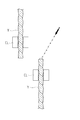
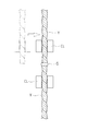
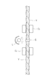
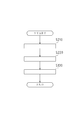
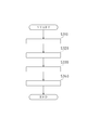
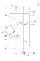
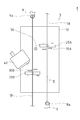
- movement of the automatic winder apparatus which concerns on one Embodiment. 1 is a front view showing a first embodiment of a yarn splicing device according to the present invention. Sectional drawing which shows an adhesive agent injection part. The figure which shows the operation
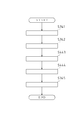
- the yarn splicing method of this embodiment mainly includes an adhesive application step S110, a butting step S120, a curing step S130, and the like.
- Adhesive application step S110 is a step of ejecting droplets of adhesive onto one of the two yarns Y.
- the adhesive in the following description is a photocurable adhesive that cures when irradiated with light of a predetermined wavelength.
- the light may be visible light or invisible light.
- the adhesive liquid is applied to the end surface of one of the two yarns Y and Y fixed by the movable clamps CL and CL. Drops are jetted.
- the adhesive droplet is a predetermined amount of droplets on the order of picoliters. In other words, each droplet of adhesive is a fine droplet that can be measured in picoliter units.
- the butting step S120 is a step of matching the two yarns Y and Y. As shown in FIG. 3, in the butting step S120, the clamp CL moves to a position where the two yarns Y and Y are butted. At this time, the clamp CL is such that the adhesive applied to one yarn Y adheres to the other yarn Y, and an adhesive layer G is formed between the two yarns Y and Y. Move to position. After the end of the matching process S120, the process proceeds to the curing process S130.
- the curing treatment step S130 is a step of curing the adhesive layer G interposed between the two yarns Y and Y.
- the light irradiation unit L irradiates the adhesive layer G interposed between the two yarns Y and Y with light including a wavelength at which the adhesive is cured. Is done.
- the adhesive layer G is cured and the two yarns Y and Y are joined.
- the adhesive layer G is cured, so that the adhesive can be cured at a desired timing and the two yarns Y and Y can be joined.
- the time required for the splicing operation can be shortened.
- the adhesive droplets are ejected onto one of the two yarns Y and Y.
- the present invention is not limited to this.
- the adhesive droplets may be ejected to both the two yarns Y and Y.
- the yarn splicing method of the present embodiment mainly includes a butting process S210, an adhesive application process S220, a curing process S130, and the like.
- the yarn splicing method of the present embodiment is different from the yarn splicing method of the first embodiment in that the order of the matching step and the adhesive application step is reversed.
- the matching step S210 is a step of matching the two yarns Y and Y. As shown in FIG. 6, in the abutting step S210, the clamp CL moves to a position where the two yarns Y and Y are abutted. At this time, the distance between the two yarns Y and Y is as short as possible, or an adhesive layer G (see FIG. 7) is applied between the yarns to be applied later. The distance is adjusted so that it can be formed. After the end of the matching step S210, the process proceeds to the adhesive application step S220.
- Adhesive application step S220 is a step of spraying adhesive droplets onto the two yarns Y and Y. As shown in FIG. 7, in the adhesive application step S ⁇ b> 220, adhesive droplets are jetted onto the portion where the two yarns Y and Y are abutted. As a result, an adhesive layer G is formed between the two yarns Y and Y.
- the adhesive droplet is a predetermined amount of droplets on the order of picoliters. In other words, each droplet of adhesive is a fine droplet that can be measured in picoliter units.
- the curing treatment step S130 is a step of curing the adhesive layer G interposed between the two yarns Y and Y.
- the light irradiation unit L irradiates the adhesive layer G interposed between the two yarns Y and Y with light including a wavelength at which the adhesive is cured. Is done.
- the adhesive layer G is cured and the two yarns Y and Y are joined.
- the adhesive layer G is cured by irradiating light from the light irradiation part L, the adhesive can be cured at a desired timing and the two yarns Y and Y can be joined. The time required for the splicing work can be shortened.
- a photo-curable adhesive is used as the adhesive, but the present invention is not limited to this. That is, various adhesives such as a dry adhesive and a moisture curable adhesive can be used as the adhesive, and the curing process S130 is performed between, for example, two yarns Y and Y. It is also possible to set it as the process of drying the interposed adhesive bond layer G.
- FIGS. 8 and 10 to 12 are right side views in which the action direction of gravity is the vertical direction, the arrow direction at the upper right in the drawing is the upward direction, and the right side in the drawing is the front side.
- the automatic winder device 100 cuts and removes the defect portion 1E (see FIG. 13) to remove the yarn. It is to improve quality.
- the automatic winder device 100 is mainly provided with a unwinding assisting device 2, a yarn splicing device 3, a yarn defect removing device 4, a traverse drum 5 and the like along the feed direction of the yarn 1. Further, one upper thread suction arm 8 and one lower thread suction arm 9 are provided in the vicinity of the yarn path of the yarn 1.
- the unwinding assisting device 2 enables high-speed winding of the yarn 1 by always applying an appropriate tension to the yarn 1 from the start to the end of winding.
- the yarn splicing device 3 cuts and removes the portion including the defective portion 1E of the yarn 1, and joins the yarn 1 divided into the upper yarn 1A and the lower yarn 1B (see FIGS. 10 and 11) by the cutting. Is.
- the yarn defect removing apparatus 4 detects the defect portion 1E of the yarn 1.
- the yarn defect removing device 4 is electrically connected to a control unit (not shown). For example, by detecting the amount of light reflected from the yarn 1 using a light emitting diode as a light source, the presence or absence of a defect portion 1E such as foreign matter is detected. Judgment.
- the traverse drum 5 is in contact with the package 7 that winds the yarn 1, and is rotated by a motor (not shown) so that the package 7 is driven to rotate and the yarn 1 is traversed (the yarn is By winding it while swinging left and right, it is possible to prevent bias when winding the package 7.
- the upper thread suction arm 8 is an intake duct that is rotatably attached to the main body of the automatic winder device 100.
- An air suction port 8a is provided at the tip of the upper yarn suction arm 8, and the upper yarn 1A can be adsorbed and held by sucking air from the air suction port 8a. Further, the upper thread suction arm 8 rotates while holding the upper thread 1A, thereby disposing the upper thread 1A at a predetermined position at the time of piecing.
- the lower thread suction arm 9 is an intake duct that is rotatably attached to the main body of the automatic winder device 100.
- An air suction port 9a is provided at the tip of the lower thread suction arm 9, and the lower thread 1B can be adsorbed and held by sucking air from the air suction port 9a. Further, the lower thread suction arm 9 rotates while holding the lower thread 1B, thereby disposing the lower thread 1B at a predetermined position at the time of piecing.
- the automatic winder apparatus 100 mainly performs a detection operation S310, a cutting operation S320, an arrangement operation S330, a yarn splicing operation S340, and the like.
- Detecting operation S310 is an operation for detecting the defective portion 1E of the yarn 1 supplied from the yarn supplying bobbin 6.
- the yarn 1 that has been unwound with appropriate assistance from the yarn feeding bobbin 6 by the unwinding assisting device 2 passes through the yarn defect removing device 4 and the traverse drum 5 sequentially. And is wound on the package 7.
- the defect 1E is detected by the yarn defect removal device 4. As described above, this is detected by changing the amount of light reflected from the yarn 1 at the defect portion 1E using a light emitting diode or the like as a light source. After completion of the detection operation S310, the process proceeds to the cutting operation S320.
- the cutting operation S320 is an operation of cutting the yarn 1 when the defective portion 1E of the yarn 1 is detected.
- the yarn defect removing device 4 detects a change in the amount of reflected light corresponding to the yarn defect, that is, when the defect portion 1E is detected, the vicinity of the yarn defect removing device 4
- the cutter (not shown) provided in the section cuts the yarn 1, and the traverse drum 5 stops rotating.
- the upper yarn 1A downstream from the cut portion of the yarn 1 is wound around the package 7, and the lower yarn 1B upstream from the cut portion of the yarn 1 is transferred to the lower yarn suction arm 9. It will be held. Since the cutting timing is delayed from the detection of the defective portion 1E, the defective portion 1E is wound around the package 7 as the upper thread 1A.
- Arrangement operation S330 is an operation of arranging the upper yarn 1A and the lower yarn 1B at predetermined positions of the yarn splicing device 3.
- the upper thread suction arm 8 is rotated upward (counterclockwise in the drawing) to bring the air suction port 8a closer to the surface of the package 7, thereby winding it around the package 7.
- the thread end of the upper thread 1A is sucked into the air suction port 8a of the upper thread suction arm 8 and held.
- the upper thread 1 ⁇ / b> A is rotated by the upper thread suction arm 8 downward (clockwise in the drawing) while holding the thread end of the upper thread 1 ⁇ / b> A, so that the upper thread 1 ⁇ / b> A is It is arranged at the position. Since the upper end of the upper thread 1A is sucked by the upper thread suction arm 8, the upper end of the upper thread 1A is stretched up and down.
- the lower thread 1B held by the lower thread suction arm 9 rotates the lower thread suction arm 9 upward while holding the lower thread 1B. It is arranged at a predetermined position of the yarn splicing device 3 by rotating counterclockwise in the figure. In addition, since the lower thread 1B is sucked by the lower thread suction arm 9, the lower thread 1B is stretched in the vertical direction. After the arrangement operation S330 is completed, the process proceeds to the yarn splicing operation S340.
- Yarn splicing operation S340 is an operation of splicing the upper thread 1A and the lower thread 1B.
- the yarn joining operation S340 the upper yarn 1A and the lower yarn 1B are joined by the yarn joining device 3 so that one yarn 1 is formed. Details of the yarn splicing operation S340 will be described later.
- the yarn 1 spliced in the splicing operation S340 is wound around the package 7 again.
- the yarn splicing device 3 which is the first embodiment of the yarn splicing device according to the present invention will be described with reference to FIGS.
- the action direction of gravity is the vertical direction
- the upper right arrow direction is the upward direction.
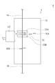
- the yarn splicing device 3 mainly includes a base 10, a clamp 20A for clamping the upper thread 1A, a clamp 20B for clamping the lower thread 1B, a cutter 30A for cutting the upper thread 1A, the yarn 1 and A cutter 30B that cuts the lower thread 1B, an adhesive injection unit 40 that supplies an adhesive for joining the upper thread 1A and the lower thread 1B, a light irradiation unit 50 for curing the adhesive, and the like are provided. These units are electrically connected to a control unit (not shown), and their operations are controlled according to a control program or the like stored in advance in the control unit.
- the adhesive in the present embodiment is a photocurable adhesive that cures when irradiated with light of a predetermined wavelength.
- the light may be visible light or invisible light.
- the base 10 is a main structure of the yarn splicing device.
- the base 10 supports the clamps 20A and 20B, the cutters 30A and 30B, and the like.
- the clamp 20A is composed of a pair of arm members arranged to face each other.
- the clamp 20A can open and close the arm member, and can close the upper member 1A disposed between the arm members by closing the arm member. Further, the clamp 20A can also move on the base 10 in the horizontal direction.
- the clamp 20B is composed of a pair of arm members arranged to face each other.
- the clamp 20B can open and close the arm member, and can close the lower thread 1B disposed between the arm members by closing the arm member.
- the clamp 20B can also move on the base 10 in the up-down direction.
- the cutter 30A is a blade using a ceramic material and cuts the upper thread 1A.
- the cutter 30A is disposed below and in the vicinity of the clamp 20A.
- the cutter 30B is a blade using a ceramic material, and cuts the lower thread 1B.
- the cutter 30B is disposed above and in the vicinity of the clamp 20B.
- the adhesive ejecting unit 40 applies the adhesive to the lower thread 1B by ejecting a droplet of adhesive onto the lower thread 1B.
- the adhesive injection unit 40 is disposed above the cutter 30B.
- the adhesive injection unit 40 mainly includes a head 41, a connecting pipe 42, a heat ray 43, a piezo element 44, a nozzle 45, and the like.
- the head 41 is a main structure of the adhesive injection unit 40.
- the head 41 includes a connection chamber 41a that receives an adhesive fed from a connection pipe 42, which will be described later, a storage chamber 41b that is connected to the connection chamber 41a and stores the adhesive, and a pressure chamber 41c branched from the storage chamber 41b. It is formed.
- connection pipe 42 is a pipe for supplying the adhesive stored in a tank (not shown) to the connection chamber 41a.
- the hot wire 43 is disposed in the connection chamber 41a and heats the adhesive to maintain a predetermined temperature.
- the temperature sensor (not shown) that detects the temperature of the heat wire 43 and the connection chamber 41a is electrically connected to a control unit (not shown).
- the control unit compares the detection result of the temperature sensor with a preset threshold value, and maintains the adhesive at a predetermined temperature by controlling on / off of the hot wire 43 based on the comparison result. Can do.
- the piezo element 44 serves as a pressure generation source for the pressure chamber 41c.
- the piezo element 44 is disposed on an upper portion of a diaphragm 44a that becomes a partition wall (an upper wall in FIG. 14) of the pressure chamber 41c.
- the piezo element 44 is electrically connected to a control unit (not shown) and expands and contracts based on a signal from the control unit.
- the nozzle 45 is opened in the pressure chamber 41c and serves as an adhesive outlet.
- the frequency of the pulse signal transmitted to the piezo element 44 and the transmission time of the pulse signal are controlled by the control unit, thereby being injected from the adhesive injection unit 40.
- the number of adhesive droplets can be controlled. Thereby, the amount of the adhesive applied by the adhesive injection unit 40 can be accurately controlled.
- the light irradiation unit 50 includes a light emitting diode or the like corresponding to the wavelength at which the adhesive is cured, and cures the photocurable adhesive.
- the light irradiation unit 50 is disposed on the side of the clamp 20A (left side in FIG. 13) and above the clamp 20B.
- the mode of the yarn splicing operation S340 performed by the yarn splicing device 3 will be described with reference to FIG. 13 and FIGS. 15 to 22.
- the action direction of gravity is the vertical direction
- the arrow direction at the upper right in the drawing is the upward direction.
- FIG. 13 shows a pair of arm members that the lower thread 1B constitutes the clamp 20B so that the upper thread 1A passes between the pair of arm members that constitute the clamp 20A by the arrangement operation S330 of the automatic winder device 100.
- Each state is shown so as to pass between the two.
- the upper thread 1 ⁇ / b> A and the lower thread 1 ⁇ / b> B are arranged so as to be parallel to each other and have the same height with respect to the base 10.
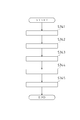
- the yarn splicing device 3 mainly performs a clamping operation S341, a cutting operation S342, an adhesive application operation S343, a butting operation S344, a curing processing operation S345, and the like in the yarn splicing operation S340.
- the clamping operation S341 is an operation for fixing the upper thread 1A and the lower thread 1B arranged at predetermined positions of the yarn splicing device 3, respectively. As shown in FIG. 16, in the clamp operation S341, the upper thread 1A and the lower thread 1B are clamped when the clamps 20A and the clamps 20B are driven to close. The defective portion 1E at the yarn end portion of the upper yarn 1A is located between the air suction port 8a of the upper yarn suction arm 8 and the clamp 20A. After the end of the clamp operation S341, the operation proceeds to the excision operation S342.
- the cutting operation S342 is an operation of cutting the upper thread 1A and the lower thread 1B at predetermined positions. As shown in FIG. 17, in cutting operation S342, the cutter 30A is driven to cut the upper thread 1A below and in the vicinity of the clamp 20A. Further, by driving the cutter 30B, the lower thread 1B is cut above and in the vicinity of the clamp 20B. As a result, the defective portion 1E is sucked into the air suction port 8a of the upper thread suction arm 8 and can be removed. Further, a portion of the lower thread 1B located above the cutter 30B is sucked and removed by the air suction port 9a of the lower thread suction arm 9. After the cutting operation S342 ends, the process proceeds to the adhesive application operation S343.
- the adhesive application operation S343 is an operation of applying an adhesive to the lower thread 1B by ejecting droplets of the adhesive onto the lower thread 1B. As shown in FIG. 18, in the adhesive application operation S343, an adhesive is applied to the lower thread 1B by the adhesive injection unit 40.
- the adhesive injection unit 40 injects an adhesive onto the end surface of the lower thread 1B (hereinafter simply referred to as “thread end surface 1n”).
- the adhesive injection unit 40 By using the adhesive injection unit 40 according to the present embodiment and adjusting the number of adhesive droplets to be injected, the supply amount of the adhesive applied to the lower thread 1B can be accurately adjusted. Accordingly, the amount of the adhesive can be accurately adjusted according to the type and diameter of the lower thread 1B (yarn 1), and useless use of the adhesive can be prevented.
- the adhesive when an adhesive is applied from the side of the yarn 1, the adhesive may not completely penetrate the yarn 1, and the inside of the yarn 1 (inside the adhesive applied to the yarn 1) ) Has a problem that the adhesive strength is reduced due to the generation of voids.
- the adhesive since the adhesive is applied to the yarn end surface 1n as described above, the adhesive easily penetrates between the fibers of the lower yarn 1B. For this reason, generation
- the adhesive injection unit 40 injects the adhesive toward the center of the yarn end surface 1n.
- the angle X formed by the axial direction of the lower thread 1B and the ejection path through which the adhesive droplet ejected by the adhesive ejecting section 40 passes is 0 degree or more and 90 degrees from the viewpoint of the configuration of the apparatus. It can be set arbitrarily in less than.
- the butting operation S344 is an operation for butting the upper thread 1A and the lower thread 1B.
- the clamp 20A moves in the horizontal direction (left direction in FIG. 20) with the upper thread 1A being clamped.
- the clamp 20B moves upward while sandwiching the lower thread 1B.
- the clamp 20A and the clamp 20B move to a position where the cut surface of the upper thread 1A and the cut surface (thread end surface 1n) of the lower thread 1B are abutted.
- the distance between the cut surface of the upper thread 1A and the cut surface (thread end surface 1n) of the lower thread 1B is such a distance that the adhesive applied to the lower thread 1B adheres to the upper thread 1A.
- the curing processing operation S345 is an operation of curing the adhesive applied to the lower thread 1B and joining the upper thread 1A and the lower thread 1B.
- the light irradiation unit 50 irradiates light, so that the adhesive applied to the lower thread 1B and attached to the upper thread 1A is cured.
- the upper thread 1A and the lower thread 1B are spliced to become one yarn 1 again.
- the time required for the yarn splicing operation can be shortened by curing the adhesive at a desired timing using the light irradiation unit 50.
- the adhesive is applied only to the lower thread 1B, but the present invention is not limited to this.
- the adhesive may be applied only to the upper thread 1A, or may be applied to the upper thread 1A and the lower thread 1B.
- the yarn splicing device 3 which is the second embodiment of the yarn splicing device according to the present invention will be described with reference to FIG.
- the action direction of gravity is the vertical direction
- the upper right arrow direction is the upward direction.
- the yarn splicing device 3 according to the second embodiment is different from the yarn splicing device 3 according to the first embodiment (see FIG. 13) in that the adhesive injection unit 40 is connected to the upper yarn 1A. It is a point arrange
- the direction of gravity action is the vertical direction
- the upper right arrow direction is the upward direction.
- the yarn splicing device 3 mainly performs a clamping operation S341, a cutting operation S342, a butting operation S443, an adhesive application operation S444, a curing processing operation S345, and the like in the yarn splicing operation S340.
- the mode of the piecing operation S340 by the piecing device 3 according to the second embodiment is different from the mode of the piecing operation S340 by the piecing device 3 according to the first embodiment (see FIG. 15).
- the point is that the order of the matching operation S443 and the adhesive application operation S444 is reversed. Since other operations are the same as the aspect of the splicing operation S340 according to the first embodiment, the same reference numerals are given and description thereof is omitted.
- the butting operation S443 is an operation in which the upper thread 1A and the lower thread 1B are butted.
- the clamp 20A moves in the horizontal direction (left direction in FIG. 23) with the upper thread 1A being sandwiched.
- the clamp 20B moves upward while sandwiching the lower thread 1B.
- the clamp 20A and the clamp 20B move to a position where the cut surface of the upper thread 1A and the cut surface (thread end surface 1n) of the lower thread 1B are abutted.
- the distance between the cut surface of the upper thread 1A and the cut surface (thread end surface 1n) of the lower thread 1B is made as close as possible, and the adhesive applied later sufficiently penetrates between the two cut surfaces. It is desirable that the distance is adjusted so that After the end of the butting operation S443, the process proceeds to the adhesive application operation S444.
- the adhesive application operation S444 is an operation of applying an adhesive to the upper thread 1A and the lower thread 1B by ejecting adhesive droplets onto the upper thread 1A and the lower thread 1B. As shown in FIG. 25, in the adhesive application operation S444, the adhesive is applied to the abutted portion between the upper thread 1A and the lower thread 1B by the adhesive injection unit 40.
- FIG. 26 it is possible to employ a configuration in which a plurality (two in FIG. 26) of adhesive injection units 40 are used.
- an adhesive agent can be osmose
- a photocurable adhesive is used as the adhesive.
- the present invention is not limited to this, and various adhesives such as a dry adhesive and a moisture curable adhesive can be used. It is also possible to use other adhesives.
- the present invention can be applied to a yarn joining method, a yarn joining device, and an automatic winder device for joining two yarns to each other using an adhesive.
Landscapes
- Spinning Or Twisting Of Yarns (AREA)
Abstract
2本の糸条を接着剤で継ぐ糸継ぎ方法であって、糸条に塗布する接着剤の供給量を正確に調節することができる糸継ぎ方法を提供することを目的とし、2本の糸条(Y・Y)を接着剤で継ぐ糸継ぎ方法であって、2本の糸条(Y・Y)のうち一方又は双方に対して接着剤の液滴を噴射する接着剤塗布工程と、2本の糸条(Y・Y)を突き合わせる突き合わせ工程と、2本の糸条(Y・Y)の間に介在する接着剤層を硬化させる硬化処理工程と、を具備する。
Description
本発明は、接着剤を用いて2本の糸条を互いに継ぐ糸継ぎ方法、糸継ぎ装置、ならびに自動ワインダ装置に関する。
従来、糸条を継ぐ技術として、2本の糸条を結ぶノッティング方式や、2本の糸端部を揃えた後に旋回気流を用いることで撚り上げるエアスプライサ方式等が知られている。ノッティング方式では、継ぎ目の強度に優れるものの、結び目ができるために、この結び目を裏地に押し込む作業等が必要であった。また、エアスプライサ方式では、撚り上げて継ぐために、継ぎ目は目立たないが強度に劣る場合や染めムラが生じる場合がある等の欠点があった。
そこで、2本の糸条の糸端部同士を突き合わせて、突き合わせ部分に接着剤を付与することで糸条を継ぐ糸継ぎ方法が提案されている(例えば特許文献1参照)。
しかしながら、特許文献1に示す糸継ぎ方法に用いられる樹脂供給手段は、接着剤となる樹脂を貯溜する本体とシリンダとから構成される注射器型のものであるため、糸条に塗布する接着剤の供給量を正確に調節し難い点で不利であった。このため、接着剤の供給量が多くなることにより、糸条の継ぎ目が硬くなる問題や、接着剤の供給量が少なくなることにより、糸条の継ぎ目の強度が低くなる問題等があった。
本発明は以上の如き状況に鑑み、糸条に塗布する接着剤の供給量を正確に調節することができる糸継ぎ方法、糸継ぎ装置、ならびに自動ワインダ装置を提供するものである。
本発明の解決しようとする課題は以上の如くであり、次にこの課題を解決するための手段を説明する。
即ち、第1の発明は、
2本の糸条を接着剤で継ぐ糸継ぎ方法であって、
前記2本の糸条のうち一方又は双方に対して接着剤の液滴を噴射する接着剤塗布工程と、
前記2本の糸条を突き合わせる突き合わせ工程と、
前記2本の糸条の間に介在する接着剤層を硬化させる硬化処理工程と、
を具備することを特徴とするものである。
2本の糸条を接着剤で継ぐ糸継ぎ方法であって、
前記2本の糸条のうち一方又は双方に対して接着剤の液滴を噴射する接着剤塗布工程と、
前記2本の糸条を突き合わせる突き合わせ工程と、
前記2本の糸条の間に介在する接着剤層を硬化させる硬化処理工程と、
を具備することを特徴とするものである。
第2の発明は、
前記接着剤塗布工程は、
前記糸条の端面に対して前記接着剤の液滴を噴射することを特徴とするものである。
前記接着剤塗布工程は、
前記糸条の端面に対して前記接着剤の液滴を噴射することを特徴とするものである。
第3の発明は、
前記接着剤は、光硬化性接着剤であり、
前記硬化処理工程は、前記接着剤層に光を照射することを特徴とするものである。
前記接着剤は、光硬化性接着剤であり、
前記硬化処理工程は、前記接着剤層に光を照射することを特徴とするものである。
第4の発明は、
2本の糸条を接着剤で継ぐ糸継ぎ装置であって、
前記2本の糸条のうち一方又は双方に対して前記接着剤の液滴を噴射する接着剤噴射部と、
前記接着剤噴射部からの液滴の数量を制御する制御部と、
を具備することを特徴とするものである。
2本の糸条を接着剤で継ぐ糸継ぎ装置であって、
前記2本の糸条のうち一方又は双方に対して前記接着剤の液滴を噴射する接着剤噴射部と、
前記接着剤噴射部からの液滴の数量を制御する制御部と、
を具備することを特徴とするものである。
第5の発明は、
前記接着剤噴射部は、前記糸条の端面に対して前記接着剤の液滴を噴射することを特徴とするものである。
前記接着剤噴射部は、前記糸条の端面に対して前記接着剤の液滴を噴射することを特徴とするものである。
第6の発明は、
前記接着剤は、光硬化性接着剤であり、
前記2本の糸条の間に介在する接着剤層に光を照射させる光照射部を更に具備することを特徴とするものである。
前記接着剤は、光硬化性接着剤であり、
前記2本の糸条の間に介在する接着剤層に光を照射させる光照射部を更に具備することを特徴とするものである。
第7の発明は、
第1から第3の発明に係る糸継ぎ装置を具備する自動ワインダ装置である。
第1から第3の発明に係る糸継ぎ装置を具備する自動ワインダ装置である。
本発明の効果として、以下に示すような効果を奏する。
第1の発明においては、噴射する接着剤の液滴の数量を制御することによって、糸条に塗布する接着剤の量を精度良く調節することができる。
第2の発明においては、糸条の端面に対して接着剤の液滴を噴射するため、糸条の繊維間に接着剤が浸透しやすい。このため、糸条の接着部分における空隙の発生を防止することができ、空隙の発生による接着力の低下を防止することができる。
第3の発明においては、光照射部から光を照射することで、2本の糸条の間に介在する接着剤層を硬化させるため、所望のタイミングで接着剤を硬化させて2本の糸条を継ぐことができ、糸継ぎ作業にかかる時間を短縮することができる。
第4の発明においては、制御部により、接着剤噴射部から噴射する接着剤の液滴の数量を制御することができるため、糸条に塗布する接着剤の量を精度良く調節することができる。
第5の発明においては、糸条の端面に対して接着剤の液滴を噴射するため、糸条の繊維間に接着剤が浸透しやすい。このため、糸条の接着部分における空隙の発生を防止することができ、空隙の発生による接着力の低下を防止することができる。
第6の発明においては、光照射部から光を照射することで、2本の糸条の間に介在する接着剤層を硬化させるため、所望のタイミングで接着剤を硬化させて2本の糸条を継ぐことができ、糸継ぎ作業にかかる時間を短縮することができる。
第7の発明においては、糸継ぎ作業に使用する接着剤の量を精度良く調節することができ、巻き取る糸条の接着部の強度を安定させることができる。
まず、図1から図4までを用いて、本発明に係る糸継ぎ方法の第1実施形態について説明する。
図1に示すように、本実施形態の糸継ぎ方法は、主に接着剤塗布工程S110、突き合わせ工程S120、硬化処理工程S130等を具備する。
接着剤塗布工程S110は、2本の糸条Yのうち一方に対して接着剤の液滴を噴射する工程である。なお、以下の説明における接着剤は、所定の波長の光を照射されることによって硬化する光硬化性の接着剤である。また、当該光は、可視光又は不可視光のいずれであってもよい。
図2に示すように、接着剤塗布工程S110において、移動自在なクランプCL・CLによって固定された2本の糸条Y・Yのうち、一方の糸条Yの端面に対し、接着剤の液滴が噴射される。前記接着剤の液滴は、ピコリットルオーダーの所定量の液滴である。つまり、接着剤の各液滴は、ピコリットル単位で計測できる程度の微細な液滴である。噴射される接着剤の液滴の数量を制御することによって、糸条Yに塗布する接着剤の量を精度良く調節することができる。また、糸条Yの端面に対して接着剤の液滴を噴射するため、糸条Yの繊維間に接着剤が浸透しやすい。このため、糸条Yの接着部分における空隙の発生を防止することができ、空隙の発生による接着力の低下を防止することができる。
接着剤塗布工程S110の終了後、突き合わせ工程S120へと移行する。
接着剤塗布工程S110の終了後、突き合わせ工程S120へと移行する。
突き合わせ工程S120は、2本の糸条Y・Yを突き合わせる工程である。図3に示すように、突き合わせ工程S120において、クランプCLは2本の糸条Y・Yが突き合わされる位置まで移動する。この際、クランプCLは、一方の糸条Yに塗布された接着剤がもう一方の糸条Yに付着し、2本の糸条Y・Yの間に接着剤層Gが形成される程度の位置まで移動する。
突き合わせ工程S120の終了後、硬化処理工程S130へと移行する。
突き合わせ工程S120の終了後、硬化処理工程S130へと移行する。
硬化処理工程S130は、2本の糸条Y・Yの間に介在する接着剤層Gを硬化させる工程である。図4に示すように、硬化処理工程S130において、光照射部Lにより2本の糸条Y・Yの間に介在する接着剤層Gに対して、接着剤が硬化する波長を含む光が照射される。これによって、接着剤層Gが硬化され、2本の糸条Y・Yが継がれる。このように、光照射部Lから光を照射することで、接着剤層Gを硬化させるため、所望のタイミングで接着剤を硬化させて当該2本の糸条Y・Yを継ぐことができ、糸継ぎ作業にかかる時間を短縮することができる。
なお、本実施形態に係る接着剤塗布工程S110においては、2本の糸条Y・Yのうち一方に対して接着剤の液滴を噴射するものとしたが、本発明はこれに限るものではなく、2本の糸条Y・Y双方に対して接着剤の液滴を噴射するものとしてもよい。
以下では、図5から図7までを用いて、本発明に係る糸継ぎ方法の第2実施形態について説明する。
図5に示すように、本実施形態の糸継ぎ方法は、主に突き合わせ工程S210、接着剤塗布工程S220、硬化処理工程S130等を具備する。
本実施形態の糸継ぎ方法は、突き合わせ工程と接着剤塗布工程の順序が逆である点で、第1実施形態の糸継ぎ方法と異なる。
突き合わせ工程S210は、2本の糸条Y・Yを突き合わせる工程である。図6に示すように、突き合わせ工程S210において、クランプCLは2本の糸条Y・Yが突き合わされる位置まで移動する。この際、当該2本の糸条Y・Yの間の距離は、可能な限り短い距離か、あるいは、後に塗布される接着剤が両糸条の間に接着剤層G(図7参照)を形成できる程度の距離に調節される。
突き合わせ工程S210の終了後、接着剤塗布工程S220へと移行する。
突き合わせ工程S210の終了後、接着剤塗布工程S220へと移行する。
接着剤塗布工程S220は、2本の糸条Y・Yに対して接着剤の液滴を噴射する工程である。図7に示すように、接着剤塗布工程S220において、2本の糸条Y・Yが突き合わされた部分に、接着剤の液滴が噴射される。これによって、当該2本の糸条Y・Yの間に接着剤層Gが形成される。前記接着剤の液滴は、ピコリットルオーダーの所定量の液滴である。つまり、接着剤の各液滴は、ピコリットル単位で計測できる程度の微細な液滴である。噴射される接着剤の液滴の数量を制御することによって、2本の糸条Y・Yに塗布する接着剤の量を精度良く調節することができる。
硬化処理工程S130は、2本の糸条Y・Yの間に介在する接着剤層Gを硬化させる工程である。図4に示すように、硬化処理工程S130において、光照射部Lにより2本の糸条Y・Yの間に介在する接着剤層Gに対して、接着剤が硬化する波長を含む光が照射される。これによって、接着剤層Gが硬化され、2本の糸条Y・Yが継がれる。このように、光照射部Lから光を照射することで、接着剤層Gを硬化させるため、所望のタイミングで接着剤を硬化させて2本の糸条Y・Yを継ぐことができ、糸継ぎ作業にかかる時間を短縮することができる。
なお、上述した実施形態においては、接着剤として光硬化性の接着剤を用いる構成としたが、本発明はこれに限るものではない。すなわち、接着剤として乾燥性の接着剤や湿気硬化性の接着剤等、種々の接着剤を用いることが可能であり、硬化処理工程S130を、例えば、2本の糸条Y・Yの間に介在する接着剤層Gを乾燥させる工程等とすることも可能である。
次に、図8から図12までを用いて本発明に係る自動ワインダ装置の実施の一形態である自動ワインダ装置100について説明する。図8及び図10から図12までは、重力の作用方向を上下方向として、図示右上の矢印方向を上方向としており、図示右方を前側とした右側面図となっている。
図8に示すように、自動ワインダ装置100は、給糸ボビン6から供給された糸条1に欠点が発見された場合に、当該欠点部1E(図13参照)を切断、除去することによって糸品質を整えるものである。自動ワインダ装置100には、糸条1の送り方向に沿って、主に解舒補助装置2、糸継ぎ装置3、糸欠点除去装置4、ならびに綾振ドラム5等が備えられている。また、糸条1の糸道の近傍には上糸用サクションアーム8ならびに下糸用サクションアーム9が各1台備えられている。
解舒補助装置2は、糸条1に対して巻き始めから巻き終わりまで常に適切な張力を掛けることにより糸条1の高速巻取りを可能とするものである。
糸継ぎ装置3は、糸条1の欠点部1Eを含む部分の切断ならびに除去を行い、切断により上糸1Aと下糸1B(図10ならびに図11参照)とに分割された糸条1を継ぐものである。
糸欠点除去装置4は、糸条1の欠点部1Eを検出するものである。糸欠点除去装置4は、図示せぬ制御部に電気的に接続されており、例えば発光ダイオードを光源として糸条1からの反射光量を検出することで、異物混入等の欠点部1Eの有無を判断するものである。
綾振ドラム5は、糸条1を巻き取るパッケージ7に接触しており、図示せぬモータにより回転することで、パッケージ7を従動回転させるとともに、糸条1を綾振すること(糸条を左右に振りながら巻き取ること)でパッケージ7に巻き取る際の偏りを防ぐものである。
上糸用サクションアーム8は、自動ワインダ装置100の本体部に回動可能に取付けられた吸気ダクトである。上糸用サクションアーム8の先端部には、空気吸い込み口8aが設けられており、該空気吸い込み口8aより空気を吸引することによって上糸1Aを吸着して保持することができる。また、上糸用サクションアーム8は、上糸1Aを保持したまま回動することにより、糸継ぎ時における所定の位置に上糸1Aを配置する。
下糸用サクションアーム9は、自動ワインダ装置100の本体部に回動可能に取付けられた吸気ダクトである。下糸用サクションアーム9の先端部には、空気吸い込み口9aが設けられており、該空気吸い込み口9aより空気を吸引することによって下糸1Bを吸着して保持することができる。また、下糸用サクションアーム9は、下糸1Bを保持したまま回動することにより、糸継ぎ時における所定の位置に下糸1Bを配置する。
以下では、図8から図12までを用いて、自動ワインダ装置100の動作態様について説明する。
図9に示すように、自動ワインダ装置100は、主に検出動作S310、切断動作S320、配置動作S330、糸継ぎ動作S340等を行う。
検出動作S310は、給糸ボビン6から供給される糸条1の欠点部1Eを検出する動作である。
図8に示すように、検出動作S310において、給糸ボビン6から解舒補助装置2によって適切に補助されて解舒された糸条1は、糸欠点除去装置4、綾振ドラム5を順次介してパッケージ7に巻き取られる。
検出動作S310において、給紙ボビン6から供給された糸条1に異物混入等の欠点部1Eがある場合は、糸欠点除去装置4によって該欠点部1Eが検出される。これは、前述のように発光ダイオード等を光源として糸条1からの反射光量が、欠点部1Eの部分で変化することにより検出される。
検出動作S310の終了後、切断動作S320へと移行する。
検出動作S310の終了後、切断動作S320へと移行する。
切断動作S320は、糸条1の欠点部1Eを検出した際に当該糸条1を切断する動作である。
図10に示すように、切断動作S320において、糸欠点除去装置4が糸欠点に相当する反射光量の変化を検出した際、つまり、欠点部1Eを検出した際には、糸欠点除去装置4近傍に備えられた図示しないカッターが糸条1を切断し、綾振ドラム5は回転を停止する。これにより、糸条1の切断部より下流側である上糸1Aはパッケージ7に巻き取られた状態となり、糸条1の切断部より上流側である下糸1Bは下糸用サクションアーム9に保持された状態となる。なお、欠点部1Eの検出より、切断のタイミングが遅れるために、欠点部1Eは上糸1Aとしてパッケージ7に巻き取られている。
切断動作S320の終了後、配置動作S330へと移行する。
切断動作S320の終了後、配置動作S330へと移行する。
配置動作S330は、上糸1A及び下糸1Bを糸継ぎ装置3の所定の位置へ配置する動作である。
図11に示すように、配置動作S330において、上糸用サクションアーム8を上方へ回動(図示反時計回転)して空気吸い込み口8aをパッケージ7の表面に近づけることで、パッケージ7に巻き取られた上糸1Aの糸端は、上糸用サクションアーム8の空気吸い込み口8aに吸引されて、保持される。
そして、図12に示すように、上糸1Aの糸端を保持した状態で上糸用サクションアーム8を下方へ回動(図示時計回転)することで、上糸1Aは糸継ぎ装置3の所定の位置へ配置される。なお、上糸1Aの糸端は、上糸用サクションアーム8により吸引されているために上下方向に架け渡された状態となる。
一方、図12に示すように、配置動作S330において、下糸用サクションアーム9に保持されている下糸1Bは、該下糸1Bを保持した状態で下糸用サクションアーム9を上方へ回動(図示反時計回転)することで糸継ぎ装置3の所定の位置へ配置される。なお、下糸1Bは、下糸用サクションアーム9により吸引されているために上下方向に架け渡された状態となる。
配置動作S330の終了後、糸継ぎ動作S340へと移行する。
配置動作S330の終了後、糸継ぎ動作S340へと移行する。
糸継ぎ動作S340は、上糸1Aと下糸1Bとを継ぐ動作である。糸継ぎ動作S340において、糸継ぎ装置3によって上糸1Aと下糸1Bとが継がれ、1本の糸条1が形成される。糸継ぎ動作S340の詳細については、後述する。
図8に示すように、糸継ぎ動作S340において継がれた糸条1は、再びパッケージ7に巻き取られる。
次に、図13ならびに図14を用いて、本発明に係る糸継ぎ装置の第1実施形態である糸継ぎ装置3について説明する。図13においては、重力の作用方向を上下方向として、図示右上の矢印方向を上方向としている。
図13に示すように、糸継ぎ装置3は、主に基台10、上糸1Aを挟持するクランプ20A、下糸1Bを挟持するクランプ20B、上糸1Aを切断するカッター30A、糸条1ならびに下糸1Bを切断するカッター30B、上糸1Aと下糸1Bとを継ぐための接着剤を供給する接着剤噴射部40、接着剤を硬化させるための光照射部50等を備える。なお、これらは図示せぬ制御部に電気的に接続されており、当該制御部に予め記憶される制御プログラム等に従って、その動作を制御される。
なお、本実施形態における接着剤は、所定の波長の光を照射されることによって硬化する光硬化性の接着剤である。また、当該光は、可視光又は不可視光のいずれであってもよい。
基台10は、糸継ぎ装置の主たる構造体となるものである。基台10は、クランプ20A・20B、カッター30A・30B等を支持する。
クランプ20Aは、対向するように配置された一対のアーム部材から構成される。クランプ20Aは、当該アーム部材を開閉することができ、アーム部材を閉じることにより、当該アーム部材間に配置される上糸1Aを挟持することができる。また、クランプ20Aは、基台10上を水平方向に移動することもできる。
クランプ20Bは、対向するように配置された一対のアーム部材から構成される。クランプ20Bは、当該アーム部材を開閉することができ、アーム部材を閉じることにより、当該アーム部材間に配置される下糸1Bを挟持することができる。また、クランプ20Bは、基台10上を上下方向に移動することもできる。
カッター30Aは、セラミック素材を用いた刃物であって、上糸1Aを切断するものである。カッター30Aは、クランプ20Aの下方かつ近傍に配置される。また、カッター30Bは、セラミック素材を用いた刃物であって、下糸1Bを切断するものである。カッター30Bは、クランプ20Bの上方かつ近傍に配置される。
図13ならびに図14に示すように、接着剤噴射部40は、接着剤の液滴を下糸1Bに対して噴射することにより、当該下糸1Bに前記接着剤を塗布するものである。接着剤噴射部40は、カッター30Bの上方に配置される。接着剤噴射部40は、主にヘッド41、接続管42、熱線43、ピエゾ素子44、ノズル45等を備える。
図14に示すように、ヘッド41は、接着剤噴射部40の主たる構造体となるものである。ヘッド41には、後述する接続管42から送り込まれる接着剤を受ける接続室41a、接続室41aに連設されて接着剤が溜められる貯溜室41b、ならびに貯溜室41bから分岐された圧力室41cが形成される。
接続管42は、図示せぬタンクに溜められる接着剤を、接続室41aへと供給するための配管である。
熱線43は、接続室41a内に配置され、接着剤を加熱して所定の温度に維持するものである。熱線43、ならびに接続室41a内の温度を検出する図示せぬ温度センサは、図示せぬ制御部に電気的に接続される。前記制御部は、前記温度センサによる検出結果と、予め設定される閾値と、を比較し、この比較結果に基づいて熱線43をオン・オフ制御することにより、接着剤を所定の温度に保つことができる。
ピエゾ素子44は、圧力室41cに対する圧力の発生源となるものである。ピエゾ素子44は、圧力室41cの隔壁(図14における上壁)となる振動板44aの上部に配置される。ピエゾ素子44は、図示せぬ制御部に電気的に接続され、当該制御部からの信号に基づいて伸縮する。
ノズル45は、圧力室41cに開設され、接着剤の噴き出し口となるものである。
このような構成の接着剤噴射部40において、ピエゾ素子44の伸縮を受けて、図14に二点鎖線で示すごとく振動板44aが図面下方に膨らむ凸状に変位されると、圧力室41c内の容積が減少する。これによって、ノズル45から、ピコリットルオーダーの所定量の液滴からなる接着剤が噴射される。
この状態から、図14に実線で示すごとく振動板44aが平らに戻されると、圧力室41c内の容積が増加する。これによって、貯溜室41bから圧力室41cへと接着剤が供給される。これに伴って、接着剤が、図示せぬタンクから接続管42、接続室41aを介して貯溜室41bへと供給される。
このような構成の接着剤噴射部40において、前記制御部によってピエゾ素子44へと発信されるパルス信号の周波数、及び当該パルス信号の発信時間を制御することにより、接着剤噴射部40から噴射される接着剤の液滴の数量を制御することができる。これによって、接着剤噴射部40により塗布される接着剤の量を精度良く制御することができる。
図13に示すように、光照射部50は、接着剤が硬化する波長に応じた発光ダイオード等を具備し、光硬化性の接着剤を硬化させるものである。光照射部50は、クランプ20Aの側方(図13における左方)かつクランプ20Bの上方に配置される。
以下では、図13、ならびに図15から図22までを用いて、糸継ぎ装置3による糸継ぎ動作S340の態様について説明する。図16から図18、図20から図22においては、重力の作用方向を上下方向として、図示右上の矢印方向を上方向としている。
なお、図13には、自動ワインダ装置100の配置動作S330によって、上糸1Aがクランプ20Aを構成する一対のアーム部材の間を通るように、下糸1Bがクランプ20Bを構成する一対のアーム部材の間を通るように、それぞれ配置されている状態を示す。このとき、上糸1Aならびに下糸1Bは互いに平行であって、基台10に対して等しい高さとなるように配置される。このように上糸1A及び下糸1Bを配置することによって、後の突き合わせ動作S344における突き合わせを容易に行うことができる。
図15に示すように、糸継ぎ装置3は、糸継ぎ動作S340において、主にクランプ動作S341、切除動作S342、接着剤塗布動作S343、突き合わせ動作S344、硬化処理動作S345等を行う。
クランプ動作S341は、糸継ぎ装置3の所定の位置へと配置された上糸1A及び下糸1Bを、それぞれ固定する動作である。図16に示すように、クランプ動作S341において、上糸1Aならびに下糸1Bは、各クランプ20Aならびにクランプ20Bがそれぞれ閉駆動することによって挟持される。なお、上糸1Aの糸端部分にある欠点部1Eは、上糸用サクションアーム8の空気吸い込み口8aとクランプ20Aの間に位置することとなる。
クランプ動作S341の終了後、切除動作S342へと移行する。
クランプ動作S341の終了後、切除動作S342へと移行する。
切除動作S342は、上糸1Aならびに下糸1Bを、それぞれ所定の位置で切断する動作である。図17に示すように、切除動作S342において、カッター30Aが駆動されることにより、上糸1Aがクランプ20Aの下方かつ近傍において切断される。また、カッター30Bが駆動されることにより、下糸1Bがクランプ20Bの上方かつ近傍において切断される。これによって、欠点部1Eは、上糸用サクションアーム8の空気吸い込み口8aに吸引され、除去することができる。また、下糸1Bのうち、カッター30Bの上方に位置する部分は、下糸用サクションアーム9の空気吸い込み口9aに吸引されて除去される。
切除動作S342の終了後、接着剤塗布動作S343へと移行する。
切除動作S342の終了後、接着剤塗布動作S343へと移行する。
接着剤塗布動作S343は、下糸1Bに対して接着剤の液滴を噴射することにより、当該下糸1Bに接着剤を塗布する動作である。図18に示すように、接着剤塗布動作S343において、接着剤噴射部40によって接着剤が下糸1Bに塗布される。
図19に示すように、接着剤噴射部40は、下糸1Bの端面(以下、単に「糸端面1n」と記す)に対して接着剤を噴射する。本実施形態に係る接着剤噴射部40を用いて、噴射する接着剤の液滴の数量を調節することにより、下糸1Bに塗布する接着剤の供給量を正確に調節することができる。これによって、下糸1B(糸条1)の種類や径等に合わせて、接着剤の量を正確に調節することができ、無駄な接着剤の使用を防止することができる。
また、従来、糸条1の側面から接着剤を塗布する場合、当該接着剤が糸条1に完全に浸透しない場合があり、糸条1の内部(糸条1に塗布された接着剤の内部)に空隙が発生することによって接着強度が低下するという問題があった。しかし、上述の如く、糸端面1nに対して接着剤を塗布するため、下糸1Bの繊維間に接着剤が浸透しやすい。このため、糸条1の接着部分における空隙の発生を防止することができ、空隙の発生による接着力の低下を防止することができる。
また、接着剤噴射部40は、糸端面1nの中心に向けて接着剤を噴射することが望ましい。これによって、周囲の空気の流れ等の外因によって接着剤の噴射方向が多少変化した場合であっても、糸端面1nに接着剤を塗布することができる。なお、下糸1Bの軸線方向と、接着剤噴射部40により噴射される接着剤の液滴が経る噴射経路と、が成す角度Xは、装置の構成上の観点等から、0度以上90度未満で任意に設定することができる。
接着剤塗布動作S343の終了後、突き合わせ動作S344へと移行する。
接着剤塗布動作S343の終了後、突き合わせ動作S344へと移行する。
突き合わせ動作S344は、上糸1Aと下糸1Bとを突き合わせる動作である。図20に示すように、突き合わせ動作S344において、クランプ20Aは、上糸1Aを挟持した状態で水平方向(図20における左方向)に移動する。また、クランプ20Bは、下糸1Bを挟持した状態で上方向に移動する。クランプ20Aならびにクランプ20Bは、上糸1Aの切断面と、下糸1Bの切断面(糸端面1n)と、が突き合わされる位置まで移動する。この際における上糸1Aの切断面と下糸1Bの切断面(糸端面1n)との間の距離は、下糸1Bに塗布された接着剤が上糸1Aに付着する程度の距離である。
突き合わせ動作S344の終了後、硬化処理動作S345へと移行する。
突き合わせ動作S344の終了後、硬化処理動作S345へと移行する。
硬化処理動作S345は、下糸1Bに塗布された接着剤を硬化させ、上糸1Aと下糸1Bとを継ぐ動作である。図21に示すように、硬化処理動作S345において、光照射部50が光を照射することによって、下糸1Bに塗布され上糸1Aに付着した接着剤が硬化される。これによって、上糸1Aと下糸1Bとが継がれ、再び1本の糸条1となる。このように、光照射部50を用いて所望のタイミングで接着剤を硬化させることで、糸継ぎ作業にかかる時間を短縮することができる。
硬化処理動作S345の終了後、図22に示すように、クランプ20Aならびにクランプ20Bによる糸条1の固定が解除され、糸条1は再びパッケージ7に巻き取られる。クランプ20Aならびにクランプ20Bは、元の位置(図13参照)まで移動する。
なお、本実施形態においては、接着剤を下糸1Bにのみ塗布する構成としたが、本発明はこれに限るものではない。すなわち、接着剤を上糸1Aにのみ塗布する構成とすることや、上糸1Aならびに下糸1Bに塗布する構成とすることも可能である。この場合、接着部の軸径が糸条1の軸径よりも極端に大きくならないように、接着剤噴射部40による接着剤の噴射量を調節することが好ましい。
以下では、図23を用いて、本発明に係る糸継ぎ装置の第2実施形態である糸継ぎ装置3について説明する。図23においては、重力の作用方向を上下方向として、図示右上の矢印方向を上方向としている。
図23に示すように、第2実施形態に係る糸継ぎ装置3が、第1実施形態に係る糸継ぎ装置3(図13参照)と異なる点は、接着剤噴射部40が、上糸1Aと下糸1Bとが突き合わされる部分の側方に配置される点である。
以下では、図23から図26までを用いて、本実施形態に係る糸継ぎ装置3による糸継ぎ動作S340の態様について説明する。図25においては、重力の作用方向を上下方向として、図示右上の矢印方向を上方向としている。
図24に示すように、糸継ぎ装置3は、糸継ぎ動作S340において、主にクランプ動作S341、切除動作S342、突き合わせ動作S443、接着剤塗布動作S444、硬化処理動作S345等を行う。
図24に示すように、第2実施形態に係る糸継ぎ装置3による糸継ぎ動作S340の態様が、第1実施形態に係る糸継ぎ装置3による糸継ぎ動作S340の態様(図15参照)と異なる点は、突き合わせ動作S443と接着剤塗布動作S444の順序が逆である点である。その他の動作においては、第1実施形態に係る糸継ぎ動作S340の態様と同一であるため、同一の符号を付し、説明は省略する。
突き合わせ動作S443は、上糸1Aと下糸1Bとを突き合わせる動作である。図23に示すように、突き合わせ動作S443において、クランプ20Aは、上糸1Aを挟持した状態で水平方向(図23における左方向)に移動する。また、クランプ20Bは、下糸1Bを挟持した状態で上方向に移動する。クランプ20Aならびにクランプ20Bは、上糸1Aの切断面と、下糸1Bの切断面(糸端面1n)と、が突き合わされる位置まで移動する。この際における上糸1Aの切断面と下糸1Bの切断面(糸端面1n)との間の距離は、可能な限り近づけられ、後に塗布される接着剤が両切断面間に十分浸透することができる程度の距離に調節されることが望ましい。
突き合わせ動作S443の終了後、接着剤塗布動作S444へと移行する。
突き合わせ動作S443の終了後、接着剤塗布動作S444へと移行する。
接着剤塗布動作S444は、上糸1Aならびに下糸1Bに対して接着剤の液滴を噴射することにより、当該上糸1Aならびに下糸1Bに接着剤を塗布する動作である。図25に示すように、接着剤塗布動作S444において、接着剤噴射部40によって、接着剤が上糸1Aと下糸1Bとの突き合わされた部分に塗布される。
また、図26に示すように、接着剤噴射部40を複数(図26においては2台)用いる構成とすることも可能である。このように構成することにより、上糸1Aならびに下糸1Bに対して複数方向から接着剤を浸透させることができ、接着剤の空隙の発生を防止し、接着強度の低下を抑制することができる。
上述した実施形態に係る糸継ぎ装置3を、自動ワインダ装置100に具備することにより、糸条1のうち糸継ぎを行った部分の接着強度を安定させることができる。
なお、上述した実施形態においては、接着剤として光硬化性の接着剤を用いる構成としたが、本発明はこれに限るものではなく、乾燥性の接着剤や湿気硬化性の接着剤等、種々の接着剤を用いることも可能である。
本発明は、接着剤を用いて2本の糸条を互いに継ぐ糸継ぎ方法、糸継ぎ装置、ならびに自動ワインダ装置に適用できる。
Y 糸条
CL クランプ
G 接着剤層
L 光照射部
1 糸条
1A 上糸
1B 下糸
1n 糸端面
3 糸継ぎ装置
20A クランプ
20B クランプ
30A カッター
30B カッター
40 接着剤噴射部
50 光照射部
S110 接着剤塗布工程
S120 突き合わせ工程
S130 硬化処理工程
S340 糸継ぎ動作
S343 接着剤塗布動作
S344 突き合わせ動作
S345 硬化処理動作
CL クランプ
G 接着剤層
L 光照射部
1 糸条
1A 上糸
1B 下糸
1n 糸端面
3 糸継ぎ装置
20A クランプ
20B クランプ
30A カッター
30B カッター
40 接着剤噴射部
50 光照射部
S110 接着剤塗布工程
S120 突き合わせ工程
S130 硬化処理工程
S340 糸継ぎ動作
S343 接着剤塗布動作
S344 突き合わせ動作
S345 硬化処理動作
Claims (7)
- 2本の糸条を接着剤で継ぐ糸継ぎ方法であって、
前記2本の糸条のうち一方又は双方に対して接着剤の液滴を噴射する接着剤塗布工程と、
前記2本の糸条を突き合わせる突き合わせ工程と、
前記2本の糸条の間に介在する接着剤層を硬化させる硬化処理工程と、
を具備することを特徴とする糸継ぎ方法。 - 前記接着剤塗布工程は、
前記糸条の端面に対して前記接着剤の液滴を噴射することを特徴とする請求項1に記載の糸継ぎ方法。 - 前記接着剤は、光硬化性接着剤であり、
前記硬化処理工程は、前記接着剤層に光を照射することを特徴とする請求項1又は請求項2に記載の糸継ぎ方法。 - 2本の糸条を接着剤で継ぐ糸継ぎ装置であって、
前記2本の糸条のうち一方又は双方に対して前記接着剤の液滴を噴射する接着剤噴射部と、
前記接着剤噴射部からの液滴の数量を制御する制御部と、
を具備することを特徴とする糸継ぎ装置。 - 前記接着剤噴射部は、前記糸条の端面に対して前記接着剤の液滴を噴射することを特徴とする請求項4に記載の糸継ぎ装置。
- 前記接着剤は、光硬化性接着剤であり、
前記2本の糸条の間に介在する接着剤層に光を照射させる光照射部を更に具備することを特徴とする請求項4又は請求項5に記載の糸継ぎ装置。 - 請求項4から請求項6までのいずれか一項に記載の糸継ぎ装置を具備することを特徴とする自動ワインダ装置。
Applications Claiming Priority (2)
| Application Number | Priority Date | Filing Date | Title |
|---|---|---|---|
| JP2009062093A JP5312993B2 (ja) | 2009-03-13 | 2009-03-13 | 糸継ぎ方法、糸継ぎ装置、ならびに自動ワインダ装置 |
| JP2009-062093 | 2009-03-13 |
Publications (1)
| Publication Number | Publication Date |
|---|---|
| WO2010104012A1 true WO2010104012A1 (ja) | 2010-09-16 |
Family
ID=42728302
Family Applications (1)
| Application Number | Title | Priority Date | Filing Date |
|---|---|---|---|
| PCT/JP2010/053687 Ceased WO2010104012A1 (ja) | 2009-03-13 | 2010-03-05 | 糸継ぎ方法、糸継ぎ装置、ならびに自動ワインダ装置 |
Country Status (2)
| Country | Link |
|---|---|
| JP (1) | JP5312993B2 (ja) |
| WO (1) | WO2010104012A1 (ja) |
Citations (2)
| Publication number | Priority date | Publication date | Assignee | Title |
|---|---|---|---|---|
| JP2003012232A (ja) * | 2000-10-03 | 2003-01-15 | Murata Mach Ltd | 糸条の糸継ぎ方法とその継ぎ目及び糸継ぎ装置を備えた自動ワインダ |
| JP2004074153A (ja) * | 2003-08-04 | 2004-03-11 | Ricoh Co Ltd | 液状樹脂噴射装置及び樹脂接着剤を含む構造体 |
Family Cites Families (1)
| Publication number | Priority date | Publication date | Assignee | Title |
|---|---|---|---|---|
| JP4154668B2 (ja) * | 2003-05-28 | 2008-09-24 | ノードソン株式会社 | 糸状体への接着剤塗布ノズル |
-
2009
- 2009-03-13 JP JP2009062093A patent/JP5312993B2/ja not_active Expired - Fee Related
-
2010
- 2010-03-05 WO PCT/JP2010/053687 patent/WO2010104012A1/ja not_active Ceased
Patent Citations (2)
| Publication number | Priority date | Publication date | Assignee | Title |
|---|---|---|---|---|
| JP2003012232A (ja) * | 2000-10-03 | 2003-01-15 | Murata Mach Ltd | 糸条の糸継ぎ方法とその継ぎ目及び糸継ぎ装置を備えた自動ワインダ |
| JP2004074153A (ja) * | 2003-08-04 | 2004-03-11 | Ricoh Co Ltd | 液状樹脂噴射装置及び樹脂接着剤を含む構造体 |
Also Published As
| Publication number | Publication date |
|---|---|
| JP5312993B2 (ja) | 2013-10-09 |
| JP2010215322A (ja) | 2010-09-30 |
Similar Documents
| Publication | Publication Date | Title |
|---|---|---|
| KR101331016B1 (ko) | 실이음 방법 및 실이음 장치 | |
| US20140251528A1 (en) | Apparatus and methods for forming a butt splice on a running web | |
| JP2020520866A (ja) | ボビンに巻かれた材料シートを供給および接合するための方法および装置 | |
| EP2573235A2 (en) | Spinning machine | |
| JP5790541B2 (ja) | シートのスプライス装置及びスプライス方法 | |
| JP5312993B2 (ja) | 糸継ぎ方法、糸継ぎ装置、ならびに自動ワインダ装置 | |
| CN104229560B (zh) | 接纱装置、卷绕单元、纤维机械及接纱方法 | |
| JP2015172256A (ja) | ラップ自動継ぎ装置 | |
| JP2013067474A (ja) | 糸巻取機及び糸巻取ユニット | |
| EP2966022B1 (en) | Yarn winding machine and yarn winding method | |
| WO2015115384A1 (ja) | ノズル、塗布装置、及び流動物の塗布方法 | |
| JP2016102005A (ja) | 糸継装置、糸巻取機及び糸継方法 | |
| JP2003267632A (ja) | コアヤーンの糸継ぎ方法とその継ぎ目、及びコアヤーン用糸継ぎ装置を備えた自動ワインダ | |
| JP2010168192A (ja) | 糸条の糸継ぎ方法と糸条の糸継ぎ装置ならびに糸条の糸継ぎ装置を備えた自動ワインダ装置 | |
| CN100417757C (zh) | 纱条的接头方法和接头装置及设有接头装置的自动络纱机 | |
| EP2539262A1 (en) | Spliced carbon fiber tow and method and apparatus for splicing carbon fiber tow | |
| JP2006144136A (ja) | 紡績装置の運転方法及び紡績装置 | |
| JP2016102268A (ja) | 芯糸供給装置及び紡績機 | |
| JP2010137945A (ja) | トラバースガイド及びこのトラバースガイドを備える糸巻取機 | |
| JP2015224397A (ja) | 紡績機及び紡績方法 | |
| JP3697537B2 (ja) | 糸条の糸継ぎ方法とその継ぎ目及び糸継ぎ装置を備えた自動ワインダ | |
| JP2008221724A (ja) | 繊維束及びその接合方法、並びに、frp成形体の製造方法 | |
| TW201943633A (zh) | 合成纖維紗用接合器 | |
| TWI746960B (zh) | 合成纖維紗用捻接器 | |
| JP4120169B2 (ja) | 糸継ぎ装置 |
Legal Events
| Date | Code | Title | Description |
|---|---|---|---|
| 121 | Ep: the epo has been informed by wipo that ep was designated in this application |
Ref document number: 10750766 Country of ref document: EP Kind code of ref document: A1 |
|
| NENP | Non-entry into the national phase |
Ref country code: DE |
|
| 122 | Ep: pct application non-entry in european phase |
Ref document number: 10750766 Country of ref document: EP Kind code of ref document: A1 |