WO2010100724A1 - 電気泳動前処理方法及び装置 - Google Patents
電気泳動前処理方法及び装置 Download PDFInfo
- Publication number
- WO2010100724A1 WO2010100724A1 PCT/JP2009/054024 JP2009054024W WO2010100724A1 WO 2010100724 A1 WO2010100724 A1 WO 2010100724A1 JP 2009054024 W JP2009054024 W JP 2009054024W WO 2010100724 A1 WO2010100724 A1 WO 2010100724A1
- Authority
- WO
- WIPO (PCT)
- Prior art keywords
- sample
- reservoir
- buffer
- obstacle
- buffer solution
- Prior art date
- Legal status (The legal status is an assumption and is not a legal conclusion. Google has not performed a legal analysis and makes no representation as to the accuracy of the status listed.)
- Ceased
Links
Images




Classifications
-
- G—PHYSICS
- G01—MEASURING; TESTING
- G01N—INVESTIGATING OR ANALYSING MATERIALS BY DETERMINING THEIR CHEMICAL OR PHYSICAL PROPERTIES
- G01N27/00—Investigating or analysing materials by the use of electric, electrochemical, or magnetic means
- G01N27/26—Investigating or analysing materials by the use of electric, electrochemical, or magnetic means by investigating electrochemical variables; by using electrolysis or electrophoresis
- G01N27/416—Systems
- G01N27/447—Systems using electrophoresis
- G01N27/44704—Details; Accessories
Definitions
- the present invention relates to a pretreatment method and apparatus in electrophoretic analysis for analyzing a very small amount of protein, nucleic acid, drug and the like using an electrophoresis plate in fields such as biochemistry, molecular biology, and clinical practice.
- Electrophoresis plates have been proposed and used in order to facilitate the handling of the apparatus and to realize high-speed analysis and miniaturization of the apparatus (see Patent Documents 1 and 2).
- the electrophoresis plate is provided with one or a plurality of flow paths composed of capillaries for separating a sample in a substrate.
- the electrophoresis plate targeted by the present invention includes both one and a plurality of capillaries formed inside the substrate.
- the capillary formed inside is used as a separation flow path for electrophoresis.
- electrophoretic analysis using an electrophoresis plate there is a sample introduction step into the separation channel as a pretreatment for analysis.
- a method for introducing a sample into the separation channel there are a cross injection method having a sample introduction channel intersecting with the separation channel and a method for introducing a sample from one end of the separation channel.
- the sample introduction method targeted by the present invention is a method of introducing a sample from one end of the latter separation channel.
- one opening at both ends of the capillary opened on the substrate surface serves as a sample injection reservoir.
- the sample injection reservoir is formed at the bottom of the buffer reservoir that stores a buffer solution that comes into contact with the electrode during electrophoretic separation.
- a sample solution is injected into a sample injection reservoir in a state where the capillary is filled with a separation medium, and the sample is sandwiched between the samples.
- a voltage is applied between the reservoir filled with the buffer solution on the side opposite to the side and the sample solution, and the sample is introduced into the capillary by electrophoresis.
- the sample injection reservoir is washed. After washing, the reservoir is filled with a buffer solution, and then a voltage is applied from both ends of the capillary to perform electrophoretic analysis of the sample.
- the sample injection reservoir is washed after sample injection.
- a method for removing the sample remaining in the sample injection reservoir after the sample is introduced from the sample injection reservoir into the electrophoresis medium in the capillary a method called a suction removal method instead of cleaning is being studied.
- a suction removal method after a sample is introduced into the electrophoresis medium, a buffer solution is injected into a buffer reservoir provided with a sample injection reservoir at the bottom.
- the sample solution remaining in the sample injection reservoir is removed by aspirating and removing a solution larger than the volume of the sample injection reservoir, for example, twice the volume of the sample injection reservoir from the sample injection reservoir. To do. Thereafter, a voltage is applied from both ends of the capillary to perform an electrophoretic analysis of the sample.
- This suction removal method for removing the sample remaining in the sample injection reservoir is a novel method and has less influence on the end surface of the separation medium facing the reservoir than the cleaning method.
- the electrode is brought into contact with the buffer solution in the buffer reservoir 12 and the buffer solution in the buffer reservoir on the opposite side across the flow path 6, and a voltage is applied between both electrodes to cause the sample of the sample plug 18 to be separated by the separation medium 14. Electrophoretically separate.
- step (c) When supplying the buffer solution 24 to the buffer reservoir 12 in step (c), if the buffer solution 24 flows into the sample reservoir 8 vigorously, the end surface of the sample plug 18 facing the sample reservoir 8 is disturbed. When such a situation occurs, the electrophoretic separation performance is deteriorated.
- the present invention relates to an improvement in a method for replacing a residual sample solution in a sample reservoir, and prevents the end face of the sample plug from being disturbed by the flow of the buffer solution when the residual sample solution in the sample reservoir is replaced with a buffer solution.
- the object is to improve the separation performance of electrophoresis.
- the present invention is a pretreatment method for electrophoretic analysis using an electrophoretic plate having a flow path composed of capillaries for separating a sample.
- the electrophoresis plate to be used includes a first buffer reservoir for containing a buffer solution on one end side of the flow path, and a sample reservoir for introducing a sample formed at the bottom of the buffer reservoir and connected to the flow path.
- a second buffer reservoir for containing a buffer solution is provided at the other end.
- This pretreatment method includes the following steps (A) to (D).
- A filling the flow path with a separation medium;
- B filling the sample reservoir with a sample solution and filling the second buffer reservoir with a buffer solution;
- C An electrode is brought into contact with the sample solution and the buffer solution filled in the step (B), a voltage is applied between both electrodes to introduce the sample into the separation medium, and an end of the separation medium on the sample reservoir side And
- D removing the electrode on the sample side from the sample reservoir and then supplying the buffer solution to the first buffer reservoir to remove the sample solution remaining in the sample reservoir. Step of replacing with buffer solution.
- the filling of the buffer solution into the first buffer reservoir in the step (D) obstructs the opening of the sample reservoir so that the gap through which the buffer solution flows into the sample reservoir is 0.5 to 3.0 mm. This is done with the objects placed.
- An example of an obstacle is a lid member that covers the opening of the sample reservoir. In that case, it is achieved by arranging the lid member at such a height that the distance between the front end surface of the lid member and the edge of the opening of the sample reservoir is 0.5 to 3.0 mm in the gap through which the buffer solution flows. Is done. Such an obstacle is arranged so that the tip surface thereof is located above the opening of the sample reservoir.
- Another example of the obstacle is a rod-like body having a similar cross-sectional shape smaller than the opening of the sample reservoir, and the size of the cross-sectional shape of the rod-like body when the rod-like body is inserted into the opening.
- the distance between the side surface of the rod-like body and the edge of the opening of the sample reservoir is such that the gap is 0.5 to 3.0 mm.
- it is arranged so that the tip of the rod-like body is inserted into the opening of the sample reservoir.
- Step (D) is preferably performed in a state where the inner surface of the sample reservoir is hydrophilically treated. In that case, it is preferable that the bottom surface of the first buffer reservoir is also hydrophilically treated.
- the hydrophilic treatment method for example, a method using a bifunctional compound having a first functional group that reacts with the glass surface and a second functional group that polymerizes can be employed (see Patent Document 3).
- the second functional group is polymerized by bonding a monomer for imparting hydrophilicity to the second functional group.
- a monomolecular layer of a hydrophilic polymer is formed on the glass surface.
- this method for example, when ⁇ -methacryloxypropyltrimethoxysilane is used as a bifunctional compound and acrylamide is bonded as a monomer, the glass surface can be covered with a monolayer of polyacrylamide. .
- the pretreatment apparatus of the present invention is for realizing the process after the flow path is filled with the separation medium in the pretreatment method of the present invention, and the electrophoresis plate filled with the separation medium is mounted thereon.
- a substrate holding unit, a sample supply unit for supplying a sample solution to the sample reservoir of the electrophoresis plate placed on the substrate holding unit, and a first buffer reservoir of the electrophoresis plate placed on the substrate holding unit A first buffer solution supply unit configured to supply a buffer solution; a second buffer solution supply unit configured to supply a buffer solution to a second buffer reservoir of the electrophoresis plate placed on the substrate holding unit; a sample solution; and a second buffer reservoir.
- a voltage application unit including an electrode and a power supply device for applying a voltage when applying a voltage to the buffer solution and introducing a sample into the separation medium and forming a sample plug at the end of the separation medium on the sample reservoir side
- the gap through which the buffer solution flows into the sample reservoir is 0.5 to 3.0 mm, or within the opening of the sample reservoir or above the opening.
- an obstacle placement section for placing obstacles.
- the obstacle placement unit When the obstacle is a lid member that covers the opening of the sample reservoir, the obstacle placement unit includes a moving mechanism that moves the lid member in the vertical direction, and the first buffer solution supply unit buffers the first buffer reservoir.
- the lid member When the liquid is supplied, the lid member is lowered, and the lid member is arranged at a height where the distance between the front end surface of the lid member and the edge of the opening becomes the gap into which the buffer liquid flows.
- the obstacle placement unit may place the obstacle at a position where the tip surface is above the opening of the sample reservoir.
- the obstacle is a rod-like body having a similar cross-sectional shape that is smaller than the opening of the sample reservoir, and the size of the cross-sectional shape is such that when the obstacle is inserted into the sample reservoir,
- the obstacle placement unit includes a moving mechanism for moving the obstacle in the vertical direction, and the first buffer liquid supply unit is the first buffer reservoir.
- the injection port for discharging the buffer solution of the first buffer solution supply unit may be configured separately from the obstacle arrangement unit, or the obstacle arrangement unit so as to move in the vertical direction simultaneously with the obstacle. It may be attached to.
- the buffer solution can be supplied to the sample reservoir without disturbing the end surface of the sample plug on the sample reservoir side, thereby improving the separation performance without causing deterioration of the plug shape.
- FIG. 1B is an enlarged cross-sectional view showing a sample reservoir and a buffer reservoir on the cathode side in the electrophoresis plate of FIG. 1A.
- FIG. 2 is a cross-sectional view showing an example of an obstacle applied to an electrophoresis plate having a plurality of flow paths.
- Electrophoresis plate 6 Capillary 8 Sample reservoir 10 Anode-side buffer reservoir (second buffer reservoir) 12 Cathode side buffer reservoir (first buffer reservoir) DESCRIPTION OF SYMBOLS 13 Electrode 16 Sample solution 18 Sample plug by the introduced sample 20, 20a, 20b Obstacle 22 Buffer liquid injection
- the electrophoresis plate 2 has only one separation channel for separating a sample.
- the capillary 6 as a separation channel is formed inside the glass substrate 3.
- the capillary 6 has a width of 50 to 150 ⁇ m, a height of 20 to 100 ⁇ m, and a length of 10 to 500 mm, and is filled with hydroxyethyl cellulose, polyvinyl pyrrolidone, polydimethylacrylamide, polyacrylamide or the like as a separation medium.
- a buffer reservoir (first buffer reservoir) 12 that stores a buffer solution is formed on the substrate surface on one end side (cathode side) of the capillary 6.
- the buffer reservoir 12 has a cylindrical member fixed to the surface of the substrate 3.
- a sample reservoir 8 is formed at the bottom of the buffer reservoir 12 to store the sample solution for injecting the sample into the separation medium filled in the capillary 6.
- the sample reservoir 8 is connected to one end of the capillary 6 and is formed as a recess opened on the surface of the substrate 3.
- the sample reservoir 8 has a cylindrical shape with a depth of 0.5 to 2 mm and
- the inner surfaces of the buffer reservoir 12 and the sample reservoir 8 are subjected to surface treatment so as to be hydrophilic.
- surface treatment for hydrophilicity ⁇ -methacryloxypropyltrimethoxysilane was bonded to the glass surface, and then the acrylamide solution was allowed to act to cover the glass surface with a polyacrylamide monolayer.
- a buffer reservoir (second buffer reservoir) 10 that stores a buffer solution is formed on the substrate surface on the other end side (anode side) of the capillary 6.
- the buffer reservoir 10 also has a cylindrical member fixed to the surface of the substrate 3.
- a concave portion 9 is also formed at the bottom of the buffer reservoir 10, which is connected to the other end of the capillary 6 and opened on the surface of the substrate 3.
- the size of the recess 9 may be the same as or different from the size of the sample reservoir 8.
- the substrate 3 is a laminate of two glass substrates, the capillary 6 is formed as a groove on one of the opposing surfaces of the two substrates, and the sample reservoir 8 and the recess 9 are formed as through holes in one substrate. It is formed as.
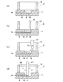
- FIG. 2 is a cross-sectional view showing the vicinity of the sample reservoir of the electrophoresis plate in order of steps in order to explain the pretreatment procedure in the electrophoresis analysis using the electrophoresis plate shown in FIGS. 1A to 1C.
- the obstacle 20 is placed above the sample reservoir 8.
- the obstacle 20 has a bottom area larger than the opening of the sample reservoir 8. Its bottom area is a flat surface.
- the position where the obstacle 20 is disposed is a position where the gap through which the buffer solution flows into the sample reservoir 8 is 0.5 to 3.0 mm.
- the buffer solution 24 is supplied from the supply port 22 of the buffer solution supply unit to the buffer reservoir 12 with the obstacle 20 placed above the sample reservoir 8.
- the buffer solution 24 enters the sample reservoir 8 through the gap between the obstacle 20 and the sample reservoir 8.
- the electrodes After removing the suction nozzle, the electrodes are brought into contact with the buffer solution 24 in the buffer reservoir 12 on the opposite side across the flow path 6 with the buffer solution 24 in the buffer reservoir 12, and a voltage is applied between the electrodes to apply the sample plug 18.
- the sample is electrophoresed and separated by the separation medium 14.
- the sample components separated by electrophoresis are detected at an appropriate position on the anode side of the flow path 6 (the side opposite to the side where the sample reservoir 8 is present).
- the detection is performed, for example, by a fluorescence measurement unit that detects fluorescence generated by irradiating the flow path 6 with excitation light.
- TTE 1-fold concentration TTE (TRIS-TAPS-EDTA) solution
- TRIS and TAPS are buffer agents
- EDTA is ethylenediaminetetraacetic acid.
- the sample solution 16 remaining in the sample reservoir 8 can be replaced with the buffer solution 24 without disturbing the end face of the sample plug 18 formed in the separation medium in the capillary 6.
- 3A-3C show some examples of obstacles.
- FIG. 3A represents the obstacle 20 shown in FIG.
- the obstacle 20 is a lid member that is disposed above the opening of the sample reservoir 8 and covers the opening.
- the front end surface 21 of the obstacle 20 is a flat surface, and the front end surface 21 is similar to the opening of the sample reservoir 8.
- a distance L between the front end surface 21 and the edge of the opening is a gap into which the buffer solution flows.
- the size of the distal end surface 21 may be larger or smaller than the opening of the sample reservoir 8, but if it is small, it cannot be so small that a predetermined gap cannot be formed.
- the obstacle 20a in FIG. 3B is a curved surface that is curved so that its tip surface 21a is convex in the tip direction. Also in this case, the distance L between the tip surface 21a and the edge of the opening is a gap into which the buffer solution flows. If the tip surface 21a is curved, the flow of the buffer solution flowing into the sample reservoir 8 is stabilized.
- 3C is a rod-like body having a similar cross-sectional shape smaller than the opening of the sample reservoir 8.
- the size of the cross-sectional shape of the obstacle 20c is such that when the obstacle 20b is inserted into the opening of the sample reservoir 8, the distance L between the side surface of the obstacle 20b and the edge of the opening becomes a gap into which the buffer solution flows. Is set to In this case, the distance L is preferably in the range of 0.5 mm to 3.0 mm, and preferably not more than 1 ⁇ 2 of the diameter of the opening of the sample reservoir 8.
- These obstacles 20, 20a, 20b are automatically arranged above or in the opening of the sample reservoir 12 when the buffer solution is supplied to the sample reservoir 12.
- FIG. 4 shows a first example of the obstacle placement unit for placing the obstacles 20, 20a, 20b.
- FIG. 4 shows a state after the buffer liquid 24 is supplied to the buffer reservoir 12.
- the electrophoresis plate 2 in which the flow path is filled with the separation medium 14 is disposed on the substrate holding unit 25 of the pretreatment apparatus of the present invention, and the separation medium 14 is transferred from the sample reservoir 12.
- the sample is introduced to form a sample plug 18 and the sample solution remains in the sample reservoir 12.
- the obstacle placement unit includes a moving mechanism 26 that is driven by a motor to move the support rod 28 in the vertical direction.
- the obstacle 20 is fixed to the tip of the support bar 28 and can be moved in the vertical direction.
- the injection nozzle 22 which is an injection port for discharging the buffer solution 24 is fixed to the support rod 28 together with the obstacle 20 so as to move in the vertical direction simultaneously with the obstacle 20.
- the obstacle 20 When supplying the buffer solution 24 to the buffer reservoir 12, as shown in FIG. 4A, the obstacle 20 is lowered and positioned at a predetermined position with respect to the opening of the sample reservoir 12. At this time, the injection nozzle 22 is also lowered and positioned at a predetermined position for supplying the buffer liquid 24 to the buffer reservoir 12. When the buffer liquid 24 is discharged from the injection nozzle 22 in this state, the buffer liquid 24 enters the sample reservoir 12 through the gap between the opening of the sample reservoir 12 and the obstacle 20.
- FIG. 5 shows the same mechanism as FIG. 4 for positioning the obstacle 20 by moving it vertically.
- the injection nozzle 22 is fixed at a predetermined position with respect to the buffer reservoir 12. Only the obstacle 20 moves up and down.
- FIG. 5 shows the case where the obstacle shown in FIG. 3A is used as an obstacle, but it can also be applied to the case where the one shown in FIG. 3B or 3C is used.
- FIGS. 6A to 6C show an example of an electrophoresis plate having a plurality of flow paths.
- a plurality of capillaries 6 are formed as separation channels for separating a sample.
- a sample reservoir 8 formed on one end side (cathode side) of each capillary 6 is formed on the bottom of a common buffer reservoir 12 formed on the surface of the substrate 3 and having a larger capacity than the sample reservoir 8.
- a recess 9 on the other end side (anode side) of each capillary 6 is shown in FIGS. 1A to 1C for each capillary 6 arranged at the bottom of a common reservoir 10 formed on the surface of the substrate 3. Same as the electrophoresis plate.
- the obstacle 20 c has as many tip surfaces as the plurality of sample reservoirs 8 arranged in the buffer reservoir 12, and supplies the buffer 24 to the buffer reservoir 12.
- the sample reservoirs 8 are positioned at predetermined positions in the openings.
- Only one injection nozzle 22 for supplying the buffer 24 is provided for the buffer reservoir 12.
- the injection nozzle 22 may be attached to the obstacle arrangement portion so as to move in the vertical direction together with the obstacle 20c, or may be fixed to a predetermined position of the buffer reservoir 12.
- FIG. 8 shows an example of an electrophoretic analyzer that includes the pretreatment device of one embodiment and performs the electrophoretic analysis after the separation medium is filled in the electrophoretic plate in the pretreatment.
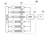
- the electrophoretic analyzer 122 includes a substrate holding unit (described in FIGS. 4 and 5), a sample supply unit 124, a second buffer solution supply unit 126, a first buffer solution supply unit 128, and a voltage application unit 130. , A fluorescence measurement unit 132, an obstacle arrangement unit 133, and a control unit 134 are provided.
- the electrophoresis plate 136 in a state where the flow path is filled with the separation medium is placed on the substrate holder.
- the sample supply unit 124 supplies a sample solution prepared in advance by an analyst at a predetermined position to the sample reservoir of the electrophoresis plate 136 placed on the substrate holding unit.
- the second buffer solution supply unit 126 supplies the buffer solution to the anode buffer reservoir (second buffer reservoir) of the electrophoresis plate 136 placed on the substrate holding unit.
- the first buffer solution supply unit 128 supplies the buffer solution to the cathode buffer reservoir (first buffer reservoir) of the electrophoresis plate 136 placed on the substrate holding unit.
- the voltage application unit 130 applies a voltage to the sample solution and the buffer solution of the second buffer reservoir to introduce the sample into the separation medium to form a sample plug at the end of the separation medium on the sample reservoir side, It includes an electrode and a power supply device for applying a voltage when the voltage is applied between the buffer solutions in the second buffer reservoir and the sample of the sample plug is electrophoretically separated by the separation medium.
- the fluorescence measuring unit 132 is for detecting the sample component electrophoretically separated by the capillary.
- the obstacle placement unit 133 is configured so that the gap in which the buffer solution flows into the sample reservoir when the first buffer solution supply unit 128 supplies the buffer solution to the first buffer reservoir is 0.5 to 3.0 mm. Place obstacles in the openings.
- the control unit 134 controls operations of the sample supply unit 124, the buffer solution supply unit 126, the replacement solution supply unit 128, the voltage application unit 130, the fluorescence measurement unit 132, and the obstacle arrangement unit 133.
- control unit 134 is connected to a personal computer (PC) 138 so that the analyst can operate while looking at the monitor.
- PC personal computer
- the sample supply unit 124, the second buffer solution supply unit 126, and the first buffer solution supply unit 128 are provided with a tank for storing each solution and a solution pump for supplying them.
- the control unit 34 controls, for example, the following operation.
- the capillary of the electrophoresis plate 136 placed on the substrate holder is already filled with the separation medium.
- the sample solution is supplied to the sample reservoir of the electrophoresis plate 136 by the sample supply unit 124, and a voltage is applied from the electrode by the voltage application unit 130 to introduce a part of the sample into the separation medium in the capillary.
- the obstacle placement unit 133 places the obstacle in a predetermined position of the opening of the sample reservoir, and the first buffer solution supply unit 128 supplies the buffer solution from the buffer reservoir on the sample side to the sample reservoir. The obstacle is removed from the sample reservoir by the obstacle placement unit 133.
- a voltage is applied between both ends of the capillary by the voltage application unit 126, and the sample is electrophoretically separated in the capillary.
- the sample component electrophoretically separated by the capillary is detected by the fluorescence measuring unit 132, and the data is transmitted to the PC 138.
- the analyst places the electrophoresis plate 136 filled with the separation medium on the substrate holding unit, prepares the sample solution and the buffer solution at predetermined positions, and causes the control unit 134 to execute the control method as described above.
- the electrophoresis analyzer can automatically perform from pretreatment to analysis.
- FIG. 9 shows the result of electrophoretic separation using the electrophoresis plate 2 of FIGS. 1A to 1C.
- the black triangle data are for the example in which the obstacle 20 shown in FIG. 3A is arranged.
- the obstacle 20 was larger than the opening of the sample reservoir 8 and was arranged so that the distance L between the edge of the opening and the front end surface of the obstacle 20 was about 0.5 mm.
- the white square data is a comparative example in which such an obstacle is not arranged.
- the horizontal axis in this graph represents the number of bases corresponding to the elapsed time from the start of measurement, and the vertical axis represents the degree of separation.
- an electrophoresis plate 2 having a volume of the sample reservoir 8 of 2.5 ⁇ L (microliter) was used.
- a sample solution a solution obtained by dissolving an ethanol-purified reaction product using BigDye (trademark) Terminator V3.1 Cycle Sequencing Kit (product of Applied Biosystems) in a solution containing 50% ethylene glycol was used.
- the buffer solution supplied from the second buffer solution supply unit 126 of FIG. 8 50 mM Tris / 50 mM TAPS / 2 mM EDTA was used.
- a solution having the same composition was used as the buffer solution supplied from the first buffer solution supply unit 128.
- the degree of separation can be improved by placing an obstacle at the opening of the sample reservoir. .
- the improvement in the separation degree in the long chain region is remarkable.
Landscapes
- Health & Medical Sciences (AREA)
- Life Sciences & Earth Sciences (AREA)
- Molecular Biology (AREA)
- Chemical & Material Sciences (AREA)
- Chemical Kinetics & Catalysis (AREA)
- Electrochemistry (AREA)
- Physics & Mathematics (AREA)
- Analytical Chemistry (AREA)
- Biochemistry (AREA)
- General Health & Medical Sciences (AREA)
- General Physics & Mathematics (AREA)
- Immunology (AREA)
- Pathology (AREA)
- Sampling And Sample Adjustment (AREA)
Abstract
試料リザーバに試料溶液を供給し、流路の分離媒体へ試料を導入した後、バッファ液を試料リザーバへ供給する。その際、試料リザーバへバッファ液が流れ込む隙間が0.5~3.0mmとなるように試料リザーバの開口部に障害物を配置した状態で、試料リザーバへバッファ液を供給する。
Description
本発明は、生化学、分子生物学、臨床などの分野において、電気泳動プレートを用いてごく微量のタンパク質や核酸、薬物などを分析する電気泳動分析における前処理方法と装置に関する。
ごく微量のタンパク質や核酸などを分析する場合、従来から電気泳動装置が用いられている。装置の取扱いを容易にし、分析の高速化と装置の小型化を実現するために、電気泳動プレートが提案され、使用されている(特許文献1,2参照。)。電気泳動プレートは基板内に試料を分離するためのキャピラリからなる流路を1又は複数個備えたものである。電気泳動プレートには、小型の基板内部に1本のキャピラリを形成したマイクロチップと、複数のキャピラリを一枚の基板に形成したマルチキャピラリー電気泳動プレートがある。本発明が対象にする電気泳動プレートは、基板内部に形成されるキャピラリが1本のものも複数のものもともに含んでいる。
電気泳動プレートでは内部に形成されたキャピラリが電気泳動用の分離流路として用いられる。電気泳動プレートを用いた電気泳動分析では、分析の前処理として分離流路への試料導入工程がある。分離流路に試料を導入する方式として、分離流路に交差する試料導入流路を備えたクロスインジェクション方式と、分離流路の一端から試料を導入する方式がある。本発明が対象にする試料導入方式は後者の分離流路の一端から試料を導入する方式である。分離流路の一端から試料を導入する方式では、基板表面に開口したキャピラリの両端の一方の開口部が試料注入用リザーバとなる。試料注入用リザーバは電気泳動分離の際に電極と接触するバッファ液が収容されるバッファリザーバの底部に形成されている。
分離流路の一端から試料を導入する方法の1つであるエレクトロカイネティックインジェクション法では、キャピラリ内が分離媒体で満たされた状態で試料注入用リザーバに試料溶液が注入され、キャピラリを挟んで試料側とは反対側でバッファ液が充填されたリザーバと試料溶液との間に電圧が印加されて電気泳動によりキャピラリ内に試料が導入される。その後、試料注入用のリザーバに残留する試料溶液を除去するために、試料注入用リザーバが洗浄される。洗浄後、そのリザーバにもバッファ液が充填された後、キャピラリの両端から電圧が印加されて試料の電気泳動分析が行われる。試料注入後に試料注入用リザーバを洗浄するのは、キャピラリ端面近傍に試料溶液が残留していると、電気泳動分析時にその残留試料がキャピラリ内に導入されてしまい、これが信号のバックグラウンドとなって現れるからである。
特開2002-310990号公報
特開2003-166975号公報
米国特許第4680201号公報
試料注入後の試料注入用リザーバの洗浄の際にキャピラリに充填されている分離媒体のリザーバに面している端面が乱されると、電気泳動により得られる電気泳動バンドの形成に影響を及ぼし、分離性能の悪化を招くという問題がある。そこで、試料注入用リザーバからキャピラリ内の泳動媒体に試料を導入した後、試料注入用リザーバに残留した試料を除去する方法として、洗浄に代わる吸引除去法と称する方法を検討している。吸引除去法では、泳動媒体に試料を導入した後、底部に試料注入用リザーバが設けられているバッファリザーバにバッファ液を注入する。そして、試料注入用リザーバ内から試料注入用リザーバの容積以上、例えば試料注入用リザーバの容積の2倍量、の溶液を吸引除去することにより、試料注入用リザーバに残留していた試料溶液を除去する。その後、キャピラリの両端から電圧が印加されて試料の電気泳動分析が行われる。試料注入用リザーバに残留した試料を除去するこの吸引除去法は新規な方法であり、洗浄法に比べて分離媒体のリザーバに面している端面に対する影響の少ない方法である。
吸引除去法を適用した電気泳動法分離方法を図10により説明する。
(a)電気泳動プレート2の流路6に分離媒体14を充填した後、試料リザーバ8に試料溶液16、流路6を挟んで反対側にあるバッファリザーバ(図示略)にバッファ液を充填する。
(a)電気泳動プレート2の流路6に分離媒体14を充填した後、試料リザーバ8に試料溶液16、流路6を挟んで反対側にあるバッファリザーバ(図示略)にバッファ液を充填する。
(b)試料溶液16に電極13を接触させ、流路6を挟んで反対側にあるバッファリザーバのバッファ液にも電極(図示略)を接触させ、両電極間に電圧を印加して分離媒体14へ試料を導入して分離媒体14の試料リザーバ8側の端部に試料プラグ18を形成する。
(c)試料側の電極13を試料リザーバ8から除去した後、試料リザーバ8につながるバッファリザーバ12へバッファ液24を供給する。このときバッファ液24は試料リザーバ8にも入っていく。
(d)試料リザーバ内の溶液を吸引ノズル23により試料リザーバ8の等量以上吸引することにより試料リザーバ8内に残っていた試料溶液16を除去し、試料リザーバ8内をバッファ液24で置換する。
(d)試料リザーバ内の溶液を吸引ノズル23により試料リザーバ8の等量以上吸引することにより試料リザーバ8内に残っていた試料溶液16を除去し、試料リザーバ8内をバッファ液24で置換する。
その後、バッファリザーバ12のバッファ液と流路6を挟んで反対側にあるバッファリザーバのバッファ液にそれぞれ電極を接触させ、両電極間に電圧を印加して試料プラグ18の試料を分離媒体14により電気泳動分離させる。
工程(c)でバッファリザーバ12にバッファ液24を供給する際、バッファ液24が勢いよく試料リザーバ8に流れ込むと、試料リザーバ8に面している試料プラグ18の端面が乱される。そのような事態が起こると、電気泳動分離性能が低下するという結果になる。
本発明は、試料リザーバの残留試料溶液の置換方法の改良に関し、試料リザーバの残留試料溶液をバッファ液で置換する際にそのバッファ液の流れによって試料プラグの端面が乱されることを防いで電気泳動の分離性能を向上させることを目的とするものである。
本発明は試料を分離するためのキャピラリからなる流路をもった電気泳動プレートを用いた電気泳動分析のための前処理方法である。使用する電気泳動プレートは流路の一端側にバッファ液を収容するための第1バッファリザーバ及びそのバッファリザーバの底部に形成されて前記流路につながる試料導入用の試料リザーバを備え、前記流路の他端にバッファ液を収容するための第2バッファリザーバを備えたものである。この前処理方法は次の工程(A)から(D)を備えている。
(A)前記流路に分離媒体を充填する工程、
(B)前記試料リザーバに試料溶液、第2バッファリザーバにバッファ液を充填する工程、
(C)工程(B)で充填された試料溶液とバッファ液にそれぞれ電極を接触させ、両電極間に電圧を印加して前記分離媒体へ試料を導入して前記分離媒体の試料リザーバ側の端部に試料プラグを形成する工程、及び
(D)試料側の電極を前記試料リザーバから除去した後、第1バッファリザーバへバッファ液を供給することにより前記試料リザーバ内に残っていた試料溶液をそのバッファ液で置換する工程。
(B)前記試料リザーバに試料溶液、第2バッファリザーバにバッファ液を充填する工程、
(C)工程(B)で充填された試料溶液とバッファ液にそれぞれ電極を接触させ、両電極間に電圧を印加して前記分離媒体へ試料を導入して前記分離媒体の試料リザーバ側の端部に試料プラグを形成する工程、及び
(D)試料側の電極を前記試料リザーバから除去した後、第1バッファリザーバへバッファ液を供給することにより前記試料リザーバ内に残っていた試料溶液をそのバッファ液で置換する工程。
そして、本発明では、工程(D)において第1バッファリザーバへのバッファ液の充填は、試料リザーバへバッファ液が流れ込む隙間が0.5~3.0mmとなるように試料リザーバの開口部に障害物を配置した状態で行われる。
障害物の一例は試料リザーバの開口部を被う蓋部材である。その場合、蓋部材の先端面と試料リザーバの開口部の縁との距離がバッファ液の流れ込む隙間の0.5~3.0mmとなるような高さの位置に蓋部材を配置することにより達成される。このような障害物はその先端面が試料リザーバの開口部の上方にくるように配置される。
障害物の他の例は、試料リザーバの開口部よりも小さい相似形の断面形状をもつ棒状体であり、その棒状体の断面形状の大きさがその棒状体が開口部内に挿入されたときその棒状体の側面と試料リザーバの開口部の縁との距離が隙間の0.5~3.0mmとなる大きさのものである。この障害物の場合、その棒状体の先端部が試料リザーバの開口部内に挿入されるように配置される。
工程(D)は試料リザーバの内面が親水性処理された状態で行われることが好ましい。その場合、さらに第1バッファリザーバの底面も親水性処理されていることが好ましい。
親水性処理方法としては、例えばガラス表面と反応する第1官能基と重合化する第2官能基をもつ二官能性化合物を使用する方法を採用することができる(特許文献3参照。)。その方法では、二官能性化合物の第1官能基をガラス表面に結合させた後、第2官能基に親水性を付与するための単量体を結合させて第2官能基を重合させることにより、ガラス表面に親水性をもつポリマーの単分子層を形成する。この方法で、例えば、二官能性化合物としてγ-メタクリルオキシプロピルトリメトキシシラン(Methacryloxypropyltrimethoxysilane)を使用し、単量体としてアクリルアミドを結合させると、ガラス表面をポリアクリルアミドの単分子層で覆うことができる。
親水性処理は試料リザーバのみに施すよりも試料リザーバと試料リザーバが底部に設けられている第1バッファリザーバの両方に同時に施す方が容易であり、またその方が本発明の目的達成の上から好都合である。
本発明の前処理装置は本発明の前処理方法のうち、流路に分離媒体が充填された後の工程を実現するためのものであり、分離媒体が充填された状態の電気泳動プレートが載置される基板保持部と、基板保持部に載置された電気泳動プレートの試料リザーバに試料溶液を供給する試料供給部と、基板保持部に載置された電気泳動プレートの第1バッファリザーバにバッファ液を供給する第1バッファ液供給部と、基板保持部に載置された電気泳動プレートの第2バッファリザーバにバッファ液を供給する第2バッファ液供給部と、試料溶液と第2バッファリザーバのバッファ液に電圧を印加して分離媒体へ試料を導入して分離媒体の試料リザーバ側の端部に試料プラグを形成する際に電圧を印加するための電極及び電源装置を含む電圧印加部と、第1バッファ液供給部が第1バッファリザーバにバッファ液を供給する際に試料リザーバへバッファ液が流れ込む隙間が0.5~3.0mmとなるように試料リザーバの開口部内又は開口部の上方に障害物を配置する障害物配置部とを備えている。
障害物が試料リザーバの前記開口部を被う蓋部材である場合、前記障害物配置部は蓋部材を上下方向に移動させる移動機構を備え、第1バッファ液供給部が第1バッファリザーバにバッファ液を供給する際に蓋部材を下降させて蓋部材の先端面と前記開口部の縁との距離がバッファ液の流れ込む前記隙間となる高さの位置に蓋部材を配置するものである。その場合、障害物配置部は障害物をその先端面が試料リザーバの開口部の上方にくる位置に配置するものとすることができる。
障害物が試料リザーバの開口部よりも小さい相似形の断面形状をもつ棒状体であり、その断面形状の大きさが、障害物が試料リザーバ内に挿入されたとき障害物の側面と開口部の縁との距離が前記隙間となる大きさに設定されているものである場合、障害物配置部は障害物を上下方向に移動させる移動機構を備え、第1バッファ液供給部が第1バッファリザーバにバッファ液を供給する際に障害物を下降させて障害物の先端部が試料リザーバの開口部の位置又はそれより下方に挿入される位置に障害物を配置するものである。
第1バッファ液供給部のバッファ液を吐出する注入口は障害物配置部とは別体として構成されたものであってもよく、又は障害物と同時に上下方向に移動するように障害物配置部に取りつけられているものであってもよい。
試料リザーバに残留する試料溶液をバッファ液で置換する際に第1バッファリザーバへのバッファ液の供給を、試料リザーバへバッファ液が流れ込む隙間が0.5~3.0mmとなるように試料リザーバの開口部に障害物を配置した状態で行われるようにすると、その障害物によって試料リザーバへ流れ込むバッファ液の流れが緩和され、試料プラグの端面の乱れが抑制される。
このようにして、試料プラグの試料リザーバ側の端面を乱すことなく試料リザーバにバッファ液を供給でき、これによってプラグ形状の劣化を招くことなく、分離性能を改善することができる。
2 電気泳動プレート
6 キャピラリ
8 試料リザーバ
10 アノード側のバッファリザーバ(第2のバッファリザーバ)
12 カソード側のバッファリザーバ(第1のバッファリザーバ)
13 電極
16 試料溶液
18 導入された試料による試料プラグ
20,20a,20b 障害物
22 バッファ液注入部
24 バッファ液
122 電気泳動分析装置
124 試料供給部
126 第2バッファ液供給部
128 第1バッファ液供給部
130 電圧印加部
132 蛍光測定部
133 障害物配置部
134 制御部
136 電気泳動プレート
6 キャピラリ
8 試料リザーバ
10 アノード側のバッファリザーバ(第2のバッファリザーバ)
12 カソード側のバッファリザーバ(第1のバッファリザーバ)
13 電極
16 試料溶液
18 導入された試料による試料プラグ
20,20a,20b 障害物
22 バッファ液注入部
24 バッファ液
122 電気泳動分析装置
124 試料供給部
126 第2バッファ液供給部
128 第1バッファ液供給部
130 電圧印加部
132 蛍光測定部
133 障害物配置部
134 制御部
136 電気泳動プレート
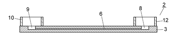
電気泳動方法におけるエレクトロカイネティック法により試料を注入する本発明の前処理方法で使用する電気泳動プレートの一例を図1A~1Cにより説明する。この電気泳動プレート2は試料を分離するための分離流路を1つだけ備えたものである。
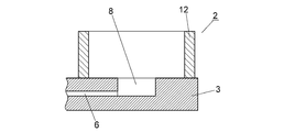
分離流路としてのキャピラリ6はガラス基板3の内部に形成されている。キャピラリ6は幅が50~150μm、高さが20~100μm、長さが10~500mmであり、内部にヒドロキシエチルセルロース、ポリビニルピロリドン、ポリジメチルアクリルアミド、ポリアクリルアミドなどが分離媒体として充填される。キャピラリ6の一端側(カソード側)の基板表面上にバッファ液を収容するバッファリザーバ(第1のバッファリザーバ)12が形成されている。バッファリザーバ12は基板3の表面に円筒部材を固着したものである。バッファリザーバ12の底部にはキャピラリ6に充填された分離媒体に試料を注入するために試料溶液を収容する試料リザーバ8が形成されている。試料リザーバ8はキャピラリ6の一端につながり、基板3の表面に開口した凹部として形成されている。試料リザーバ8は深さが0.5~2mm、直径が1~5mmの円筒状である。
バッファリザーバ12及び試料リザーバ8の内面は親水性になるように表面処理が施されている。親水性のための表面処理として、ガラス表面にγ-メタクリルオキシプロピルトリメトキシシランを結合させた後、アクリルアミド溶液を作用させることにより、ガラス表面をポリアクリルアミドの単分子層で覆った。
キャピラリ6の他端側(アノード側)の基板表面上にバッファ液を収容するバッファリザーバ(第2のバッファリザーバ)10が形成されている。バッファリザーバ10も基板3の表面に円筒部材を固着したものである。バッファリザーバ10の底部にもキャピラリ6の他端につながり、基板3の表面に開口した凹部9が形成されている。凹部9のサイズは試料リザーバ8のサイズと同じであってもよく、異なっていてもよい。
基板3は2枚のガラス基板が貼りあわされたものであり、キャピラリ6はそれらの2枚の基板の対向面の一方に溝として形成され、試料リザーバ8と凹部9は一方の基板に貫通穴として形成されている。
図2は図1Aから図1Cに示された電気泳動プレートを用いた電気泳動分析における前処理の手順を説明するために電気泳動プレートの試料リザーバ付近を工程順に示す断面図である。
(A)電気泳動プレート2の流路6に分離媒体14を充填した後、試料リザーバ8に試料溶液16、流路6を挟んで反対側にあるバッファリザーバ(図示略)にバッファ液を充填する。
(B)試料溶液16に電極13を接触させ、流路6を挟んで反対側にあるバッファリザーバのバッファ液にも電極(図示略)を接触させ、両電極間に電圧を印加して分離媒体14へ試料を導入して分離媒体14の試料リザーバ8側の端部に試料プラグ18を形成する。
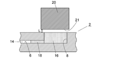
(C)試料側の電極13を試料リザーバ8から除去した後、試料リザーバ8の上方に障害物20を配置する。障害物20は試料リザーバ8の開口よりも大きい底面積をもつ。その底面積は平坦面である。障害物20を配置する位置は、試料リザーバ8へバッファ液が流れ込む隙間が0.5~3.0mmとなる位置である。
試料リザーバ8の上方に障害物20を配置した状態でバッファ液供給部の供給口22からバッファリザーバ12へバッファ液24を供給する。バッファ液24は障害物20と試料リザーバ8との隙間から試料リザーバ8に浸入する。
(D)試料リザーバ8に浸入したバッファ液24は試料リザーバ8内に残っていた試料溶液16を排除していき、試料リザーバ8内がバッファ液24で充填される。
(E)試料リザーバ8に残っている試料溶液を除去するために、試料リザーバ8に吸引ノズルを挿入し、試料リザーバ8の容量の2倍程度の量のバッファ液24を吸引して排出する。
吸引ノズルを除去した後、バッファリザーバ12のバッファ液24と流路6を挟んで反対側にあるバッファリザーバのバッファ液にそれぞれ電極を接触させ、両電極間に電圧を印加して試料プラグ18の試料を分離媒体14により電気泳動させ分離させる。
電気泳動により分離した試料成分は、流路6のアノード側(試料リザーバ8がある側とは反対側)の適当な位置で検出される。検出は例えば流路6に励起光を照射し発生する蛍光を検出する蛍光測定部により行われる。
試料溶液16の溶媒として例えばサンガー反応物の蒸留水溶解液を使用し、バッファ液24としては例えば1倍濃度TTE(TRIS‐TAPS‐EDTA)溶液を使用する。ここで、TRISとTAPSは緩衝剤、EDTAはエチレンジアミン四酢酸である。
図2に示した前処理方法では、キャピラリ6内の分離媒体に形成された試料プラグ18の端面を乱すことなく試料リザーバ8に残留した試料溶液16をバッファ液24で置換することができる。
図3A~3Cに障害物のいくつかの例を示す。
図3Aは図2に示されている障害物20を表わしている。障害物20は試料リザーバ8の開口部に上方に配置されて開口部を被う蓋部材である。障害物20の先端面21は平坦面であり、先端面21は試料リザーバ8の開口部と相似形である。先端面21と開口部の縁との距離Lがバッファ液の流れ込む隙間となる。先端面21の大きさは試料リザーバ8の開口部に対して大きくても小さくてもよいが、小さい場合は所定の隙間を形成することができないほど小さくすることはできない。
図3Bの障害物20aはその先端面21aが先端方向に凸形状になるように湾曲した曲面となったものである。この場合も先端面21aと開口部の縁との距離Lがバッファ液の流れ込む隙間となる。湾曲した先端面21aであれば、試料リザーバ8に流れ込むバッファ液の流れが安定する。
図3Cの障害物20bは試料リザーバ8の開口部よりも小さい相似形の断面形状をもつ棒状体である。この障害物20cの断面形状の大きさは障害物20bが試料リザーバ8の開口部内に挿入されたとき障害物20bの側面と開口部の縁との距離Lがバッファ液の流れ込む隙間となる大きさに設定されている。この場合、距離Lの大きさは0.5mm~3.0mmの範囲内であり、また試料リザーバ8の開口部の直径の1/2以下とすることが好ましい。
これらの障害物20,20a,20bは試料リザーバ12へバッファ液が供給されるときに自動的に試料リザーバ12の開口部の上方又は開口部内に配置されるものである。
障害物20,20a,20bを配置する障害物配置部の第1の例は図4に示されたものである。図4はバッファリザーバ12にバッファ液24が供給された後の状態を示している。バッファ液24が供給されるときは、流路に分離媒体14が充填された状態の電気泳動プレート2が本発明の前処理装置の基板保持部25上に配置され、試料リザーバ12から分離媒体14に試料が導入されて試料プラグ18が形成され、試料リザーバ12には試料溶液が残留した状態となっている。障害物配置部はモータにより駆動されて支持棒28を上下方向に移動させる移動機構26を備えている。障害物20は支持棒28の先端に固定されて上下方向に移動させられるようになっている。
バッファ液24を吐出する注入口である注入ノズル22は障害物20と同時に上下方向に移動するように、障害物20とともに支持棒28に固定されている。
バッファ液24をバッファリザーバ12に供給するときは、図4の(A)に示されるように、障害物20が下降して試料リザーバ12の開口部に対する所定の位置に位置決めされる。このとき注入ノズル22も同時に下降し、バッファリザーバ12にバッファ液24を供給する所定の位置に位置決めされる。その状態で注入ノズル22からバッファ液24が吐出されると、バッファ液24は試料リザーバ12の開口部と障害物20の隙間を経て試料リザーバ12内に進入する。
バッファ液24の供給が完了すると、図4の(B)に示されるように、障害物20と注入ノズル22がバッファリザーバ12の上方まで同時に上昇させられる。
図5は障害物20を上下方向に移動させて位置決めする機構は図4のものと同じである。この例では、注入ノズル22はバッファリザーバ12に対する所定の位置に固定されている。障害物20のみが上下方向に移動する。
図4と図5の障害物配置部は障害物として図3Aのものを用いる場合を示しているが、図3B又は図3Cのものを使用する場合にも適用することができる。
ここまでの説明は図1A~1Cに示された1本の流路をもつ電気泳動プレートを用いる場合を示しているが、複数本の流路をもつ電気泳動プレートを用いる場合にも適用することができる。
図6A~6Cは複数本の流路をもつ電気泳動プレートの一例を示したものである。この電気泳動プレート2では、試料を分離するための分離流路としてのキャピラリ6が複数本形成されている。それぞれのキャピラリ6の一端側(カソード側)に形成された試料リザーバ8は、基板3の表面に形成されて試料リザーバ8よりも大きい容量をもつ共通のバッファリザーバ12の底部に形成されている。それぞれのキャピラリ6の他端側(アノード側)の凹部9は基板3の表面に形成された共通のリザーバ10の底部に配置されている1本ずつのキャピラリ6については図1A~1Cに示された電気泳動プレートと同じである。
この電気泳動プレートの場合、図7に示されるように、障害物20cはバッファリザーバ12内に配置された複数の試料リザーバ8の数だけの先端面をもち、バッファリザーバ12にバッファ24を供給するときは全ての試料リザーバ8の開口部の所定の位置に位置決めされる。バッファ24を供給する注入ノズル22はバッファリザーバ12について1個のみが設けられている。注入ノズル22は障害物20cとともに上下方向に移動するように障害物配置部に取り付けられたものであってもよく、バッファリザーバ12の所定の位置に固定されたものであってもよい。
図8は一実施例の前処理装置を含み、前処理のうちの電気泳動プレートへの分離媒体充填後から電気泳動分析までを行なう電気泳動分析装置の一例を示している。この電気泳動分析装置122は、基板保持部(図4、図5に記載されている。)、試料供給部124、第2バッファ液供給部126、第1バッファ液供給部128、電圧印加部130、蛍光測定部132、障害物配置部133及び制御部134を備えている。
基板保持部には流路に分離媒体が充填された状態の電気泳動プレート136が載置される。
試料供給部124は、分析者によって予め所定の位置に用意された試料溶液を基板保持部に載置された電気泳動プレート136の試料リザーバに供給するものである。
第2バッファ液供給部126は、基板保持部に載置された電気泳動プレート136のアノード側バッファリザーバ(第2バッファリザーバ)にバッファ液を供給するものである。
第1バッファ液供給部128は、基板保持部に載置された電気泳動プレート136のカソード側バッファリザーバ(第1バッファリザーバ)にバッファ液を供給するものである。
電圧印加部130は試料溶液と第2バッファリザーバのバッファ液に電圧を印加して分離媒体へ試料を導入して分離媒体の試料リザーバ側の端部に試料プラグを形成する際と、第1、第2バッファリザーバ内のバッファ液間に電圧を印加して試料プラグの試料を分離媒体により電気泳動分離させる際に電圧を印加するための電極及び電源装置を含んでいる。
蛍光測定部132はキャピラリで電気泳動分離された試料成分を検出するためのものである。
障害物配置部133は、第1バッファ液供給部128が第1バッファリザーバにバッファ液を供給する際に試料リザーバへバッファ液が流れ込む隙間が0.5~3.0mmとなるように試料リザーバの開口部に障害物を配置する。
制御部134は、試料供給部124、バッファ液供給部126、置換用液供給部128、電圧印加部130、蛍光測定部132及び障害物配置部133の動作を制御する。
また、分析者がモニタを見ながら操作することができるように、制御部134はパーソナルコンピュータ(PC)138に接続されている。
試料供給部124、第2バッファ液供給部126及び第1バッファ液供給部置128はそれぞれの溶液を貯留するタンクとそれらを送液する送液ポンプなどを備えている。
制御部34は例えば以下の動作を行なうように制御する。
基板保持部に載置された電気泳動プレート136のキャピラリにはすでに分離媒体が充填されている。
まず試料供給部124によって電気泳動プレート136の試料リザーバに試料溶液を供給させ、電圧印加部130によって電極から電圧を印加させてキャピラリ内の分離媒体に試料の一部を導入させる。その後、障害物配置部133によって試料リザーバの開口部の所定の位置に障害部を配置し、第1バッファ液供給部128によってバッファ液を試料側のバッファリザーバから試料リザーバに供給させる。障害物配置部133によって障害物を試料リザーバから除去する。第2バッファ液供給部126によって試料側と反対側のバッファリザーバにバッファ液を供給させた後、電圧印加部126によってキャピラリの両端間に電圧を印加して、キャピラリにおいて試料を電気泳動分離させる。キャピラリで電気泳動分離された試料成分を蛍光測定部132によって検出し、PC138にそのデータを送信する。
分析者は、分離媒体が充填された電気泳動プレート136を基板保持部に載置し、試料溶液及びバッファ液を所定の位置に用意して上記のような制御方法を制御部134により実行させることにより、電気泳動分析装置が前処理から分析までを自動で行なうことができる。
図1A~1Cの電気泳動プレート2を使用した電気泳動分離の結果を図9に示す。黒三角のデータは図3Aに示された障害物20を配置した実施例のものである。障害物20は試料リザーバ8の開口部よりも大きいものを使用し、その開口部の縁と障害物20の先端面との距離Lが0.5mm程度となるように配置した。一方、白四角のデータはそのような障害物を配置しなかった比較例である。このグラフにおける横軸は測定開始からの経過時間に対応する塩基数を表わし、縦軸は分離度を表わしている。実施例と比較例のデータを得た測定では、ともに試料リザーバ8の残留試料溶液を除去するために吸引ノズルにより試料リザーバ8から試料リザーバ8の容量の2倍程度のバッファ液を吸引して除去する吸引除去法を適用した。
ここで、(分離度)=0.25×S×(N)1/2
である。Sは分離選択性、Nは理論段数を表し、以下のように定義される。
S=2(Ti-Tj)/(Ti+Tj)(i-j)
T:移動時間
i,j:塩基数
N=5.5×(Ti/WW0.5)
WW0.5:塩基数iのピークの半値幅
である。Sは分離選択性、Nは理論段数を表し、以下のように定義される。
S=2(Ti-Tj)/(Ti+Tj)(i-j)
T:移動時間
i,j:塩基数
N=5.5×(Ti/WW0.5)
WW0.5:塩基数iのピークの半値幅
この測定では、試料リザーバ8の容量が2.5μL(マイクロリットル)の電気泳動プレート2を使用した。試料溶液として、BigDye(商標) Terminator V3.1 Cycle Sequencing Kit(Applied Biosystems社の製品)を用いてエタノール精製した反応生成物を、50%エチレングリコールを含む溶解液に溶解したものを用いた。図8の第2バッファ液供給部126から供給されるバッファ液として、50mM Tris/50mM TAPS/2mM EDTAを用いた。第1バッファ液供給部128から供給されるバッファ液として、同じ組成の溶液を使用した。
図9の結果によれば、キャピラリ内の分離媒体への試料導入後、試料リザーバ内にバッファ液を供給する際に試料リザーバの開口部に障害物を配置することにより分離度の向上がみられる。特に長鎖領域での分離度の向上が著しい。
Claims (12)
- 試料を分離するためのキャピラリからなる流路をもった電気泳動プレートを用いた電気泳動分析のための前処理方法であって、
前記電気泳動プレートは前記流路の一端側にバッファ液を収容するための第1バッファリザーバ及びそのバッファリザーバの底部に形成されて前記流路につながる試料導入用の試料リザーバを備え、前記流路の他端にバッファ液を収容するための第2バッファリザーバ一を備えたものであり、
(A)前記流路に分離媒体を充填する工程、
(B)前記試料リザーバに試料溶液、第2バッファリザーバにバッファ液を充填する工程、
(C)工程(B)で充填された試料溶液とバッファ液にそれぞれ電極を接触させ、両電極間に電圧を印加して前記分離媒体へ試料を導入して前記分離媒体の試料リザーバ側の端部に試料プラグを形成する工程、及び
(D)試料側の電極を前記試料リザーバから除去した後、第1バッファリザーバへバッファ液を供給する工程を順に備え、
前記工程(D)において第1バッファリザーバへのバッファ液の供給は、前記試料リザーバへバッファ液が流れ込む隙間が0.5~3.0mmとなるように前記試料リザーバの開口部に障害物を配置した状態で行われる前処理方法。 - 前記障害物は前記試料リザーバの前記開口部を被う蓋部材であり、
前記蓋部材の先端面と前記開口部の縁との距離がバッファ液の流れ込む前記隙間となる高さの位置に前記蓋部材を配置する請求項1に記載の前処理方法。 - 前記障害物はその先端面が前記試料リザーバの前記開口部の上方にくるように配置される請求項2に記載の前処理方法。
- 前記障害物は前記試料リザーバの前記開口部よりも小さい相似形の断面形状をもつ棒状体であり、前記棒状体の前記断面形状の大きさは前記棒状体が前記開口部内に挿入されたとき前記棒状体の側面と前記開口部の縁との距離が前記隙間となる大きさであり、
前記棒状体はその先端部が前記開口部内に挿入される請求項1に記載の前処理方法。 - 前記工程(D)は前記試料リザーバの内面が親水性処理された状態で行われる請求項1から4のいずれか一項に記載の前処理方法。
- 前記工程(D)は第1バッファリザーバの底面も親水性処理された状態で行われる請求項5に記載の前処理方法。
- 前記工程(D)の後、前記障害物を除去し、前記試料リザーバ内から試料リザーバの容量以上のバッファ液を吸引して除去することにより試料リザーバの残留試料溶液を除去する請求項1から6のいずれか一項に記載の前処理方法。
- 試料を分離するためのキャピラリからなる流路をもった電気泳動プレートを用いた電気泳動分析のための前処理装置であって、
前記電気泳動プレートは前記流路の一端側にバッファ液を収容するための第1バッファリザーバ及びそのバッファリザーバの底部に形成されて前記流路につながる試料導入用の試料リザーバを備え、前記流路の他端にバッファ液を収容するための第2バッファリザーバ一を備えたものであり、
該前処理装置は、
前記流路に分離媒体が充填された状態の前記電気泳動プレートが載置される基板保持部と、
前記基板保持部に載置された電気泳動プレートの前記試料リザーバに試料溶液を供給する試料供給部と、
前記基板保持部に載置された電気泳動プレートの第1バッファリザーバにバッファ液を供給する第1バッファ液供給部と、
前記基板保持部に載置された電気泳動プレートの第2バッファリザーバにバッファ液を供給する第2バッファ液供給部と、
試料溶液と第2バッファリザーバのバッファ液に電圧を印加して分離媒体へ試料を導入して分離媒体の試料リザーバ側の端部に試料プラグを形成する際に電圧を印加するための電極及び電源装置を含む電圧印加部と、
第1バッファ液供給部が第1バッファリザーバにバッファ液を供給する際に前記試料リザーバへバッファ液が流れ込む隙間が0.5~3.0mmとなるように前記試料リザーバの開口部内又は開口部の上方に障害物を配置する障害物配置部と、を備えている前処理装置。 - 前記障害物は前記試料リザーバの前記開口部を被う蓋部材であり、
前記障害物配置部は前記蓋部材を上下方向に移動させる移動機構を備え、第1バッファ液供給部が第1バッファリザーバにバッファ液を供給する際に前記蓋部材を下降させて前記蓋部材の先端面と前記開口部の縁との距離がバッファ液の流れ込む前記隙間となる高さの位置に前記蓋部材を配置するものである請求項8に記載の前処理装置。 - 前記障害物配置部は前記障害物をその先端面が前記試料リザーバの前記開口部の上方にくる位置に配置するものである請求項9に記載の前処理装置。
- 前記障害物は前記試料リザーバの前記開口部よりも小さい相似形の断面形状をもつ棒状体であり、前記断面形状の大きさは前記障害物が前記試料リザーバ内に挿入されたとき前記障害物の側面と前記開口部の縁との距離が前記隙間となる大きさに設定されており、
前記障害物配置部は前記障害物を上下方向に移動させる移動機構を備え、第1バッファ液供給部が第1バッファリザーバにバッファ液を供給する際に前記障害物を下降させて前記障害物の先端部が前記開口部の位置又はそれより下方に挿入される位置に前記障害物を配置するものである請求項8に記載の前処理装置。 - 第1バッファ液供給部のバッファ液を吐出する注入口は前記障害物と同時に上下方向に移動するように前記障害物配置部に取りつけられている請求項9から11のいずれか一項に記載の前処理装置。
Priority Applications (1)
| Application Number | Priority Date | Filing Date | Title |
|---|---|---|---|
| PCT/JP2009/054024 WO2010100724A1 (ja) | 2009-03-04 | 2009-03-04 | 電気泳動前処理方法及び装置 |
Applications Claiming Priority (1)
| Application Number | Priority Date | Filing Date | Title |
|---|---|---|---|
| PCT/JP2009/054024 WO2010100724A1 (ja) | 2009-03-04 | 2009-03-04 | 電気泳動前処理方法及び装置 |
Publications (1)
| Publication Number | Publication Date |
|---|---|
| WO2010100724A1 true WO2010100724A1 (ja) | 2010-09-10 |
Family
ID=42709302
Family Applications (1)
| Application Number | Title | Priority Date | Filing Date |
|---|---|---|---|
| PCT/JP2009/054024 Ceased WO2010100724A1 (ja) | 2009-03-04 | 2009-03-04 | 電気泳動前処理方法及び装置 |
Country Status (1)
| Country | Link |
|---|---|
| WO (1) | WO2010100724A1 (ja) |
Citations (2)
| Publication number | Priority date | Publication date | Assignee | Title |
|---|---|---|---|---|
| JP2002310990A (ja) * | 2001-04-13 | 2002-10-23 | Shimadzu Corp | 電気泳動装置 |
| JP2003166975A (ja) * | 2001-11-30 | 2003-06-13 | Shimadzu Corp | 電気泳動部材用リザーバ部材及び電気泳動部材 |
-
2009
- 2009-03-04 WO PCT/JP2009/054024 patent/WO2010100724A1/ja not_active Ceased
Patent Citations (2)
| Publication number | Priority date | Publication date | Assignee | Title |
|---|---|---|---|---|
| JP2002310990A (ja) * | 2001-04-13 | 2002-10-23 | Shimadzu Corp | 電気泳動装置 |
| JP2003166975A (ja) * | 2001-11-30 | 2003-06-13 | Shimadzu Corp | 電気泳動部材用リザーバ部材及び電気泳動部材 |
Similar Documents
| Publication | Publication Date | Title |
|---|---|---|
| US8187442B2 (en) | Microchip processing method and apparatus | |
| JPH11502618A (ja) | キャピラリー電気泳動装置および方法 | |
| JP4362987B2 (ja) | マイクロチップ電気泳動におけるサンプル導入方法 | |
| US6517696B1 (en) | Capillary electrophoretic apparatus, sample plate and sample injection method | |
| US20100116661A1 (en) | Electrophoretic chip and a method of electrophoresis | |
| US20060266649A1 (en) | Electrophoretic member, electrophoretic device, electrophoretic method and sample dispensing probe | |
| US7651599B2 (en) | High density fluidic chip design and method of sample injection | |
| JP3562460B2 (ja) | 電気泳動装置 | |
| WO2010100724A1 (ja) | 電気泳動前処理方法及び装置 | |
| JP4457919B2 (ja) | 電気泳動プレート | |
| JP6072619B2 (ja) | 電気泳動装置 | |
| JP2003156475A (ja) | チップ型電気泳動装置 | |
| JP4645255B2 (ja) | 分析試料調製用溶媒 | |
| JP4692628B2 (ja) | 電気泳動の前処理方法及び電気泳動用前処理装置 | |
| JP4507922B2 (ja) | キャピラリープレートを用いた試料注入方法 | |
| JP5310605B2 (ja) | マイクロチップ電気泳動方法及び装置 | |
| US6994778B2 (en) | Microfluidic device and analyzing method using the same | |
| JP2002303605A (ja) | サンプルの前処理方法及び電気泳動用チップ | |
| KR20090027650A (ko) | 전기영동의 전처리 방법, 분석용 기판 및 전기영동용 전처리 장치 | |
| GB2439233A (en) | Electrophoretic Separation Method | |
| JP2012202805A (ja) | 電気泳動装置 |
Legal Events
| Date | Code | Title | Description |
|---|---|---|---|
| 121 | Ep: the epo has been informed by wipo that ep was designated in this application |
Ref document number: 09841089 Country of ref document: EP Kind code of ref document: A1 |
|
| NENP | Non-entry into the national phase |
Ref country code: DE |
|
| 122 | Ep: pct application non-entry in european phase |
Ref document number: 09841089 Country of ref document: EP Kind code of ref document: A1 |
|
| NENP | Non-entry into the national phase |
Ref country code: JP |