WO2010098455A1 - 排出係数算定器および排出係数算定方法 - Google Patents
排出係数算定器および排出係数算定方法 Download PDFInfo
- Publication number
- WO2010098455A1 WO2010098455A1 PCT/JP2010/053128 JP2010053128W WO2010098455A1 WO 2010098455 A1 WO2010098455 A1 WO 2010098455A1 JP 2010053128 W JP2010053128 W JP 2010053128W WO 2010098455 A1 WO2010098455 A1 WO 2010098455A1
- Authority
- WO
- WIPO (PCT)
- Prior art keywords
- emission
- power
- power generation
- coefficient
- generation amount
- Prior art date
- Legal status (The legal status is an assumption and is not a legal conclusion. Google has not performed a legal analysis and makes no representation as to the accuracy of the status listed.)
- Ceased
Links
Images


Classifications
-
- G—PHYSICS
- G06—COMPUTING OR CALCULATING; COUNTING
- G06Q—INFORMATION AND COMMUNICATION TECHNOLOGY [ICT] SPECIALLY ADAPTED FOR ADMINISTRATIVE, COMMERCIAL, FINANCIAL, MANAGERIAL OR SUPERVISORY PURPOSES; SYSTEMS OR METHODS SPECIALLY ADAPTED FOR ADMINISTRATIVE, COMMERCIAL, FINANCIAL, MANAGERIAL OR SUPERVISORY PURPOSES, NOT OTHERWISE PROVIDED FOR
- G06Q30/00—Commerce
- G06Q30/04—Billing or invoicing
-
- G—PHYSICS
- G06—COMPUTING OR CALCULATING; COUNTING
- G06Q—INFORMATION AND COMMUNICATION TECHNOLOGY [ICT] SPECIALLY ADAPTED FOR ADMINISTRATIVE, COMMERCIAL, FINANCIAL, MANAGERIAL OR SUPERVISORY PURPOSES; SYSTEMS OR METHODS SPECIALLY ADAPTED FOR ADMINISTRATIVE, COMMERCIAL, FINANCIAL, MANAGERIAL OR SUPERVISORY PURPOSES, NOT OTHERWISE PROVIDED FOR
- G06Q50/00—Information and communication technology [ICT] specially adapted for implementation of business processes of specific business sectors, e.g. utilities or tourism
- G06Q50/06—Energy or water supply
-
- H—ELECTRICITY
- H02—GENERATION; CONVERSION OR DISTRIBUTION OF ELECTRIC POWER
- H02J—ELECTRIC POWER NETWORKS; CIRCUIT ARRANGEMENTS OR SYSTEMS FOR SUPPLYING OR DISTRIBUTING ELECTRIC POWER; SYSTEMS FOR STORING ELECTRIC ENERGY
- H02J13/00—Circuit arrangements for providing remote monitoring or remote control of equipment in a power distribution network
- H02J13/12—Monitoring network conditions, e.g. electrical magnitudes or operational status
-
- H—ELECTRICITY
- H02—GENERATION; CONVERSION OR DISTRIBUTION OF ELECTRIC POWER
- H02J—ELECTRIC POWER NETWORKS; CIRCUIT ARRANGEMENTS OR SYSTEMS FOR SUPPLYING OR DISTRIBUTING ELECTRIC POWER; SYSTEMS FOR STORING ELECTRIC ENERGY
- H02J3/00—Circuit arrangements for AC mains or AC distribution networks
- H02J3/28—Arrangements for balancing of the load in networks by storage of energy
- H02J3/32—Arrangements for balancing of the load in networks by storage of energy using batteries or super capacitors with converting means
-
- H—ELECTRICITY
- H02—GENERATION; CONVERSION OR DISTRIBUTION OF ELECTRIC POWER
- H02J—ELECTRIC POWER NETWORKS; CIRCUIT ARRANGEMENTS OR SYSTEMS FOR SUPPLYING OR DISTRIBUTING ELECTRIC POWER; SYSTEMS FOR STORING ELECTRIC ENERGY
- H02J13/00—Circuit arrangements for providing remote monitoring or remote control of equipment in a power distribution network
- H02J13/10—Circuit arrangements for providing remote monitoring or remote control of equipment in a power distribution network characterised by displaying of information or by user interaction, e.g. supervisory control and data acquisition [SCADA] systems
-
- H—ELECTRICITY
- H02—GENERATION; CONVERSION OR DISTRIBUTION OF ELECTRIC POWER
- H02J—ELECTRIC POWER NETWORKS; CIRCUIT ARRANGEMENTS OR SYSTEMS FOR SUPPLYING OR DISTRIBUTING ELECTRIC POWER; SYSTEMS FOR STORING ELECTRIC ENERGY
- H02J2101/00—Supply or distribution of decentralised, dispersed or local electric power generation
- H02J2101/20—Dispersed power generation using renewable energy sources
-
- H—ELECTRICITY
- H02—GENERATION; CONVERSION OR DISTRIBUTION OF ELECTRIC POWER
- H02J—ELECTRIC POWER NETWORKS; CIRCUIT ARRANGEMENTS OR SYSTEMS FOR SUPPLYING OR DISTRIBUTING ELECTRIC POWER; SYSTEMS FOR STORING ELECTRIC ENERGY
- H02J3/00—Circuit arrangements for AC mains or AC distribution networks
- H02J3/38—Arrangements for feeding a single network from two or more generators or sources in parallel; Arrangements for feeding already energised networks from additional generators or sources in parallel
- H02J3/381—Dispersed generators
-
- Y—GENERAL TAGGING OF NEW TECHNOLOGICAL DEVELOPMENTS; GENERAL TAGGING OF CROSS-SECTIONAL TECHNOLOGIES SPANNING OVER SEVERAL SECTIONS OF THE IPC; TECHNICAL SUBJECTS COVERED BY FORMER USPC CROSS-REFERENCE ART COLLECTIONS [XRACs] AND DIGESTS
- Y02—TECHNOLOGIES OR APPLICATIONS FOR MITIGATION OR ADAPTATION AGAINST CLIMATE CHANGE
- Y02E—REDUCTION OF GREENHOUSE GAS [GHG] EMISSIONS, RELATED TO ENERGY GENERATION, TRANSMISSION OR DISTRIBUTION
- Y02E40/00—Technologies for an efficient electrical power generation, transmission or distribution
- Y02E40/70—Smart grids as climate change mitigation technology in the energy generation sector
-
- Y—GENERAL TAGGING OF NEW TECHNOLOGICAL DEVELOPMENTS; GENERAL TAGGING OF CROSS-SECTIONAL TECHNOLOGIES SPANNING OVER SEVERAL SECTIONS OF THE IPC; TECHNICAL SUBJECTS COVERED BY FORMER USPC CROSS-REFERENCE ART COLLECTIONS [XRACs] AND DIGESTS
- Y02—TECHNOLOGIES OR APPLICATIONS FOR MITIGATION OR ADAPTATION AGAINST CLIMATE CHANGE
- Y02E—REDUCTION OF GREENHOUSE GAS [GHG] EMISSIONS, RELATED TO ENERGY GENERATION, TRANSMISSION OR DISTRIBUTION
- Y02E60/00—Enabling technologies; Technologies with a potential or indirect contribution to GHG emissions mitigation
-
- Y—GENERAL TAGGING OF NEW TECHNOLOGICAL DEVELOPMENTS; GENERAL TAGGING OF CROSS-SECTIONAL TECHNOLOGIES SPANNING OVER SEVERAL SECTIONS OF THE IPC; TECHNICAL SUBJECTS COVERED BY FORMER USPC CROSS-REFERENCE ART COLLECTIONS [XRACs] AND DIGESTS
- Y02—TECHNOLOGIES OR APPLICATIONS FOR MITIGATION OR ADAPTATION AGAINST CLIMATE CHANGE
- Y02E—REDUCTION OF GREENHOUSE GAS [GHG] EMISSIONS, RELATED TO ENERGY GENERATION, TRANSMISSION OR DISTRIBUTION
- Y02E70/00—Other energy conversion or management systems reducing GHG emissions
- Y02E70/30—Systems combining energy storage with energy generation of non-fossil origin
-
- Y—GENERAL TAGGING OF NEW TECHNOLOGICAL DEVELOPMENTS; GENERAL TAGGING OF CROSS-SECTIONAL TECHNOLOGIES SPANNING OVER SEVERAL SECTIONS OF THE IPC; TECHNICAL SUBJECTS COVERED BY FORMER USPC CROSS-REFERENCE ART COLLECTIONS [XRACs] AND DIGESTS
- Y02—TECHNOLOGIES OR APPLICATIONS FOR MITIGATION OR ADAPTATION AGAINST CLIMATE CHANGE
- Y02P—CLIMATE CHANGE MITIGATION TECHNOLOGIES IN THE PRODUCTION OR PROCESSING OF GOODS
- Y02P90/00—Enabling technologies with a potential contribution to greenhouse gas [GHG] emissions mitigation
- Y02P90/80—Management or planning
- Y02P90/84—Greenhouse gas [GHG] management systems
-
- Y—GENERAL TAGGING OF NEW TECHNOLOGICAL DEVELOPMENTS; GENERAL TAGGING OF CROSS-SECTIONAL TECHNOLOGIES SPANNING OVER SEVERAL SECTIONS OF THE IPC; TECHNICAL SUBJECTS COVERED BY FORMER USPC CROSS-REFERENCE ART COLLECTIONS [XRACs] AND DIGESTS
- Y04—INFORMATION OR COMMUNICATION TECHNOLOGIES HAVING AN IMPACT ON OTHER TECHNOLOGY AREAS
- Y04S—SYSTEMS INTEGRATING TECHNOLOGIES RELATED TO POWER NETWORK OPERATION, COMMUNICATION OR INFORMATION TECHNOLOGIES FOR IMPROVING THE ELECTRICAL POWER GENERATION, TRANSMISSION, DISTRIBUTION, MANAGEMENT OR USAGE, i.e. SMART GRIDS
- Y04S10/00—Systems supporting electrical power generation, transmission or distribution
- Y04S10/12—Monitoring or controlling equipment for energy generation units, e.g. distributed energy generation [DER] or load-side generation
- Y04S10/123—Monitoring or controlling equipment for energy generation units, e.g. distributed energy generation [DER] or load-side generation the energy generation units being or involving renewable energy sources
-
- Y—GENERAL TAGGING OF NEW TECHNOLOGICAL DEVELOPMENTS; GENERAL TAGGING OF CROSS-SECTIONAL TECHNOLOGIES SPANNING OVER SEVERAL SECTIONS OF THE IPC; TECHNICAL SUBJECTS COVERED BY FORMER USPC CROSS-REFERENCE ART COLLECTIONS [XRACs] AND DIGESTS
- Y04—INFORMATION OR COMMUNICATION TECHNOLOGIES HAVING AN IMPACT ON OTHER TECHNOLOGY AREAS
- Y04S—SYSTEMS INTEGRATING TECHNOLOGIES RELATED TO POWER NETWORK OPERATION, COMMUNICATION OR INFORMATION TECHNOLOGIES FOR IMPROVING THE ELECTRICAL POWER GENERATION, TRANSMISSION, DISTRIBUTION, MANAGEMENT OR USAGE, i.e. SMART GRIDS
- Y04S10/00—Systems supporting electrical power generation, transmission or distribution
- Y04S10/14—Energy storage units
-
- Y—GENERAL TAGGING OF NEW TECHNOLOGICAL DEVELOPMENTS; GENERAL TAGGING OF CROSS-SECTIONAL TECHNOLOGIES SPANNING OVER SEVERAL SECTIONS OF THE IPC; TECHNICAL SUBJECTS COVERED BY FORMER USPC CROSS-REFERENCE ART COLLECTIONS [XRACs] AND DIGESTS
- Y04—INFORMATION OR COMMUNICATION TECHNOLOGIES HAVING AN IMPACT ON OTHER TECHNOLOGY AREAS
- Y04S—SYSTEMS INTEGRATING TECHNOLOGIES RELATED TO POWER NETWORK OPERATION, COMMUNICATION OR INFORMATION TECHNOLOGIES FOR IMPROVING THE ELECTRICAL POWER GENERATION, TRANSMISSION, DISTRIBUTION, MANAGEMENT OR USAGE, i.e. SMART GRIDS
- Y04S10/00—Systems supporting electrical power generation, transmission or distribution
- Y04S10/30—State monitoring, e.g. fault, temperature monitoring, insulator monitoring, corona discharge
-
- Y—GENERAL TAGGING OF NEW TECHNOLOGICAL DEVELOPMENTS; GENERAL TAGGING OF CROSS-SECTIONAL TECHNOLOGIES SPANNING OVER SEVERAL SECTIONS OF THE IPC; TECHNICAL SUBJECTS COVERED BY FORMER USPC CROSS-REFERENCE ART COLLECTIONS [XRACs] AND DIGESTS
- Y04—INFORMATION OR COMMUNICATION TECHNOLOGIES HAVING AN IMPACT ON OTHER TECHNOLOGY AREAS
- Y04S—SYSTEMS INTEGRATING TECHNOLOGIES RELATED TO POWER NETWORK OPERATION, COMMUNICATION OR INFORMATION TECHNOLOGIES FOR IMPROVING THE ELECTRICAL POWER GENERATION, TRANSMISSION, DISTRIBUTION, MANAGEMENT OR USAGE, i.e. SMART GRIDS
- Y04S10/00—Systems supporting electrical power generation, transmission or distribution
- Y04S10/40—Display of information, e.g. of data or controls
-
- Y—GENERAL TAGGING OF NEW TECHNOLOGICAL DEVELOPMENTS; GENERAL TAGGING OF CROSS-SECTIONAL TECHNOLOGIES SPANNING OVER SEVERAL SECTIONS OF THE IPC; TECHNICAL SUBJECTS COVERED BY FORMER USPC CROSS-REFERENCE ART COLLECTIONS [XRACs] AND DIGESTS
- Y04—INFORMATION OR COMMUNICATION TECHNOLOGIES HAVING AN IMPACT ON OTHER TECHNOLOGY AREAS
- Y04S—SYSTEMS INTEGRATING TECHNOLOGIES RELATED TO POWER NETWORK OPERATION, COMMUNICATION OR INFORMATION TECHNOLOGIES FOR IMPROVING THE ELECTRICAL POWER GENERATION, TRANSMISSION, DISTRIBUTION, MANAGEMENT OR USAGE, i.e. SMART GRIDS
- Y04S50/00—Market activities related to the operation of systems integrating technologies related to power network operation or related to communication or information technologies
- Y04S50/12—Billing, invoicing, buying or selling transactions or other related activities, e.g. cost or usage evaluation
Definitions
- the present invention relates to an emission coefficient calculator and a calculation method that enable active DSM (Demand Side Management) control around a carbon dioxide emission coefficient.
- DSM Demand Side Management
- the present invention has been made in view of the above-described circumstances, and provides an emission coefficient calculator for eliminating the inconsistency in supply and demand, realizing reduction of CO 2 emissions and active use of excessive power.
- the purpose is to do.
- the emission coefficient calculator of the present invention includes a receiving unit that receives the emission coefficient in the upper system at regular intervals, and a received amount that measures the accumulated electric energy received from the upper system as the received amount.
- a measurement unit a power generation amount measurement unit for measuring a power generation amount generated by zero emission power in the system, and a substantial emission of the system according to a ratio between the power reception amount and the power generation amount and an emission factor of a higher system.
- an emission coefficient calculating means for calculating the coefficient at regular intervals, wherein the emission coefficient calculating means notifies the substantial emission coefficient to a load or a subordinate system.
- the emission coefficient calculator of the present invention it is possible to eliminate the inconsistency in supply and demand, to reduce CO 2 emissions and to actively use excessive power.
- the block diagram of the emission coefficient calculator of embodiment The figure which shows the simplified example of the change of the effective emission coefficient of one day.
- the same numbered portions are assumed to perform the same operation, and repeated description is omitted.
- the load maximizes the adjustable output at a timing at which cheaper and less discharged power can be used.
- zero emission power refers to power from a power source that does not emit CO 2 or the like for power generation, such as wind power or solar cells.
- the emission coefficient calculator of this embodiment realizes local production and local consumption of power supply by installing various power supply sources such as microgrid devices, that is, storage batteries, fuel cells, solar cells, wind power generation, etc., close to consumers.
- a microgrid device is installed between the customer side and the upper power system, the effect is calculated, and an emission coefficient calculator is installed in order to match supply and demand.
- the emission factor calculator calculates the carbon dioxide emission factor, etc. according to the efficiency of the microgrid equipment that changes from moment to moment, and communicates it to the lower level system or load by communication means (or makes it available to the lower level system or load). (Acquired by communication means).
- the lower system or load performs load control independently based on the value or change amount of the transmitted emission coefficient. Needless to say, the load control may not be performed independently, and the controller may perform the centralized control by looking at the discharge coefficient.
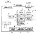
- the emission coefficient calculator of the embodiment will be described with reference to FIG.
- a device part without hatching is an essential component
- a device part with hatching is an optional element that is not an essential component.
- the essential components are a higher system emission coefficient reception unit 101, a higher system power reception amount measurement unit 102, a zero emission power generation amount measurement unit 103, and an energy mix emission coefficient calculation unit 104.
- non-essential components include a battery discharge coefficient calculation unit 111, a battery charge / discharge amount measurement unit 112, a fuel cell discharge coefficient calculation unit 113, a fuel cell power generation amount measurement unit 114, a neighboring ZE past power generation amount measurement value reception unit 115, The neighborhood ZE past power generation actual value accumulation unit 116, the neighborhood ZE future power generation amount estimation unit 117, and the energy mix emission coefficient forecast unit 118.
- These non-essential components will be described later in the fifth and sixth embodiments.
- the higher system emission coefficient receiving unit 101 has a function of receiving emission coefficient information separately calculated in the upper system and holding the emission coefficient for a certain period of time.
- This has communication means that can obtain the emission coefficient of the higher system (for example, if it is a B2B cooperation API by WebService, its WSDL URL and SOAP Proxy object, etc.), and this is inquired every fixed time or from the upper system The latest value is updated as much as possible by pushing the data, and the latest value and a finite number of the past values are held in the memory. Past values are overwritten in order from the oldest. The value of this memory is returned at the time of inquiry from the energy mix emission coefficient calculation unit 104.
- the emission coefficient of the upper system is calculated by the ratio of the CO 2 emission amount of the used fuel and the amount of power sold, which is obtained from the operation plan and the operation results of each generator in the commercial system.
- the value at this time may be a rough value according to the operation plan, or may be a detailed value obtained as a result of measuring the fuel at regular intervals.
- the emission coefficient calculator 100 according to the embodiment of the present invention may be used in a regional system or an in-house system.
- the upper system power reception amount measurement unit 102 In response to the inquiry from the energy mix emission coefficient calculation unit 104, the upper system power reception amount measurement unit 102 returns the integrated power amount received from the upper system.
- the zero emission power generation amount measurement unit 103 calculates the power generation amount by an electric power source such as wind power or a solar cell that does not emit CO 2 to the power generation. Return in form.
- the energy mix emission coefficient calculation unit 104 operates at regular time intervals (measurement intervals). Assume that at a certain time t, an upper system emission coefficient Fs (t), an upper system power reception amount Ps (t), and a zero emission power generation amount Pz (t) are given. For the two operations t (current measurement time) and t ⁇ 1 (previous measurement time) that are operated with a certain interval, the calculation unit 104 calculates a substantial emission coefficient F at time t according to the following equation (1). (T) is calculated.
- the energy mix emission coefficient calculation unit 104 notifies the emission coefficient.
- a communication means such as Publish-Subscribe may be used, or a WebService API may be prepared to wait for an inquiry from a load or a subordinate system.
- the emission coefficient information (emission coefficient information) calculated by the emission coefficient calculator 100 according to the embodiment of the present invention includes the following items.
- Measurement section start time Last measurement time (t-1 in equation (1))
- Measurement section end time current measurement time (t in equation (1))
- Emission factor Emission factor calculated for the time interval (F (t) in equation (1))
- the emission coefficient information obtained from the upper level may include the above three items.
- the emission coefficient transmission unit in the higher-level system has a function of returning emission coefficient information of a plurality of latest sections in response to the inquiry. This is because it is possible to perform a compensation measure when the section is shifted in the calculation on the lower side.
- the transmission of the emission factor in a simple upper system may be a single emission factor that does not include a time interval.
- the CO 2 emission coefficient that changes every moment is fed back to the demand side, whereby the mismatch in supply and demand can be resolved. If the load side performs control such that electric power is used when the emission coefficient is low, it is inevitably possible to achieve both reduction of CO 2 emission and active use of excess electric power.
- Example 1 Utilization for load control in demand area systems
- an adjustable load such as an electric vehicle, an air conditioner, a water heater, etc.
- an emission coefficient calculator according to the embodiment of the present invention. The following shows an example of controlling the load that does not easily affect the convenience of residents even if the use of the service is temporarily stopped.
- FIG. 4 consider air conditioning control in a home where a microgrid device is introduced.
- the air conditioning control controls the air temperature toward the set temperature.
- electric power is required in proportion to the control amount, the control timing and temperature accuracy are not strict. There is a certain degree that the user feels uncomfortable even before and after a little.
- a simple model is considered in which the emission coefficient calculator 100 of the microgrid operation unit 401 has a web server, and a real emission coefficient at that time can be obtained by accessing a specific URL by HTTP.
- other communication forms including the Publish-Subscribe type may be used.
- Advantages of the known Push type communication such as controlling the communication only when the change amount of the CO 2 emission coefficient exceeds a certain threshold (or rate) by using the publish-subscribe type communication mode. Can be used.
- the air conditioner 403 can be controlled by ECHONET (registered trademark) or a similar protocol.
- Bluetooth (registered trademark) or the like is used for communication between the home server 402 and the air conditioner 403.
- the home server communicates using a local network such as a VDSL network.
- the home server existing in each house knows the network address (in this case, the URL for access) of the emission coefficient calculator 100 of the microgrid operation unit 401 connected to the home.
- the air conditioner 403 has a mode setting function for performing a load adjustment function.
- the eco operation mode is a mode in which air conditioning is weaker than usual. In summer, it is not very cold, and in winter it can be done with minimal heating. Energy consumption is the lowest.
- the normal operation mode is as usual, and the acceleration operation mode uses higher energy than usual to reach the target set temperature sooner, or excessively considering future energy savings (cooler in summer and hotter in winter) )Control.
- the control may be returned to the normal control after making the excessive control state once. That is, the state of performing control exceeding the temperature target value set by the user may or may not be continued.
- ECHONET in ECHONET SPECIFICATION APPENDIX ECHONET device object detailed specification Version 3.21Release b published from ECHONET CONSORTIUM, the device object details of the home air conditioner class are specified in section 1.2.1.
- rapid operation mode setting there is an item of rapid operation mode setting, and three exclusive operation modes of normal operation / rapid / silent are defined.
- a property for setting three modes of “eco / normal / acceleration” as an eco-drive mode may be prepared, or it may be redefined that the same control is performed within the interpretation range of the rapid operation mode setting. .
- the eco-operation mode is set. Note that F decreases when the connected microgrid equipment sufficiently generates zero emission power, so TL is determined assuming the level of the decrease.
- protection logic is introduced such that a random waiting time is set when switching to eco-operation mode, and switching is performed only when the emission coefficient continues to meet the threshold condition during the waiting time. May be.
- each load device acquires the emission factor from the emission factor calculator and performs an operation corresponding to the emission factor.
- the threshold value is not directly determined by the home server 402 as described here, but the emission coefficient is directly read, and the average emission coefficient is calculated. You may determine how much electric power is used by calculating
- the method of using the emission factor calculator in a system composed of a microgrid device in a condominium and the like, a home server 402 of each house, and a load has been shown. This is a microgrid device in an office or factory. The same effect can be achieved by constructing an equivalent system in a system composed of a control panel and a load of each device.
- a calculation load in a data center or the like can be considered.
- FIG. 5 shows an example in which a load is connected via a commercial system, an intermediate system having jurisdiction over a region, etc., or a customer system existing in a condominium or a business office.
- the emission factor information calculated by the commercial grid is used by the intermediate grid, and the eco-efficiency of the power generated by the microgrid equipment in the intermediate grid is divided into the lower-ranked emission factor information that is prorated from the commercial grid. Passed to the customer system.
- Example 3 Accounting for carbon dioxide emissions
- the causes are diverse and cannot be easily rejected, but one of the causes is that the individual load is small, and the results of the reduction efforts and the cost may not be balanced.
- incentives for reduction which is one reason why efforts to reduce emissions do not progress.
- the amount of carbon dioxide emission can be calculated by multiplying the amount of power consumption (kWh) by the current emission coefficient (kg / kWh). More precisely, a sufficiently accurate polynomial approximation to the emission coefficient and power consumption with respect to time can be considered, and it can be obtained by integrating this, but measurement and modeling to obtain its accuracy It is difficult. Therefore, in the embodiment of the present invention, the emission amount is obtained by the method described below.
- the time synchronization mechanism (NTP: NetworkTime Protocol or IEEE 1588 or other known means may be used) is used to synchronize the time and synchronize the measurement section of the higher system with the measurement section of the lower system with high accuracy. .
- the power received from the host system and the power of various power supply devices in the microgrid device are measured at fixed time intervals synchronized with the host system, and the corresponding memory is secured and recorded. At this time, since a higher emission coefficient has not been obtained, a value meaning “uncalculated” (minus 1 in this embodiment) is entered.
- the energy mix emission coefficient calculation unit has a memory or a database constituting an array having the following structure as a unit.
- the array can be indexed in time series, and ⁇ Ps (t) and ⁇ Pz (t) are calculated based on this (formula (1)).
- Measurement time-Upper system power received Integrated amount of power received from upper system at measurement time-Upper system emission coefficient: Emission coefficient calculated in upper system (minus means uncalculated) ⁇
- Zero emission power generation measurement part Zero emission power generation integrated value at the time of measurement ⁇
- Emission factor Real emission factor in this system for the measurement section (minus means uncalculated)
- Emissions Real emissions below this system for the measurement section. Also, regarding inquiries about emission factor information from the load or subordinate system, the latest memory structure for which emission factor calculation has been completed and the previous one. Emission factor information is constructed from the memory structure and responds.
- the calculation of the substantial and automatic emission coefficient and load control based on the present invention is an original device that enhances the effect of introducing microgrid equipment. It is.
- the baseline of CO 2 emissions related to electricity use is the average power factor of the power system multiplied by the total power consumption: the average power system emissions as the baseline amount in the baseline and credit method Use the coefficient (current emission factor) multiplied by the total power consumption.
- Emission credit allocation (emission transfer from electric power company) is automatically performed from the contracted amount of power: Emission credit allocation is automatically performed by the cap-and-trade method. It is a method that requires a reasonable burden according to the amount of electricity contract, and may have a stronger emission reduction effect. On the other hand, it is considered difficult for energy companies to impose restrictions on emission credits on their customers, so appropriate system design is necessary.
- the discharge amount that can be calculated in the embodiment of the present invention is the total amount of all loads below the system of each hierarchy. Therefore, in the case of multiple layers, if the emission reduction effect is calculated in each layer, the effect is calculated in multiple. Therefore, the following method is considered for the amount of emissions at each level.
- the intermediate hierarchy has a subordinate system that includes the emission coefficient calculator according to the present invention and a subordinate system that does not include the subordinate system.
- Emissions and emission credits in the middle tier are obtained by subtracting the sum of the emission amounts and emission rights of the subordinate systems with emission coefficient calculators from their own emission amounts and emission rights.
- the emission reduction effect due to the introduction of the microgrid equipment in the middle hierarchy is the sum of the reduction effects for the lower systems not equipped with the emission coefficient calculator.
- Method 2 in the subordinate system including the emission factor calculator according to the embodiment of the present invention, including the emission calculation based on the emission factor given from the upper level of the middle tier, and the effect of the microgrid equipment in the middle tier The amount of emissions is calculated based on the emission factor, and this difference is transferred as a contribution of the middle class from the emission rights or credits of the lower grid to the middle class.
- the calculation function of the real emission coefficient in the embodiment of the present invention and the calculation function of the real emission amount in a configuration in which this is combined in multiple layers are the implementation of the present invention. This is due to the effect of the energy mix emission coefficient calculation unit 104 specific to the form.
- Fourth embodiment Handling three or more energy sources
- two energy sources of power reception from the upper system and zero emission power generation are considered.
- mixed utilization of heat and electric power (cogeneration) using a gas turbine engine or a fuel cell is considered.
- the hot water supply is the first purpose and the supply of electric power is the second purpose, the power supplied as a secondary by supplying the necessary amount of hot water is zero emission. You can also think about it.
- the consumption of fuel such as gas will certainly lead to the emission of carbon dioxide gas, so we measure this and count the loss calculated from the heat utilization efficiency and the amount of hot water stored as the amount of electricity discharged There is also.
- Example 5 Handling of rechargeable batteries
- a rechargeable battery or a capacitor such as SCiB (registered trademark) is taken into the microgrid device. Due to the presence of the rechargeable battery, a time shift of the electric energy can be performed. It can store excessively generated electricity, such as short-term sunny days in winter, and release it when heating energy demand such as rain and snow increases. At this time, the rechargeable battery is both a load and a power source.
- the basic algorithm of rechargeable battery control is to maintain the median capacity within a possible range in order to suppress short-time fluctuations.
- the load frequency is monitored by monitoring the power supply frequency and voltage.
- overload frequency delay or voltage drop occurs
- discharge starts, and underload (advance frequency or voltage increase) Recharge at some times.
- underload advanced frequency or voltage increase
- there is an apparatus that periodically performs an automatic refresh operation full charge ⁇ discharge cycle).
- control is performed so that the median value of the capacity is maintained in the long term.
- the median capacity is the center point.
- a method of allocating from the capacity zero to full charge and charging / discharging up to the capacity corresponding to the current voltage / frequency is considered for either of the allowable voltage / frequency fluctuations or their combination. That is, when the complete discharge is 0 and the full charge is 1 with respect to the capacity c, for example, whether to charge or discharge when the voltage v is applied, the following equation (voltage charge / discharge function Cv (c , V)).
- This algorithm uses the emission coefficient calculator in the embodiment of the present invention.
- power may be stored when the amount of power generation connected to the microgrid device is high, and may be discharged when the amount of power generation connected to the microgrid device is low.
- the amount of power generation varies depending on the nature of each microgrid device and the operating status of the connected device. Therefore, in this algorithm, the power quality of the system, that is, the emission coefficient is used.
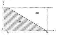
- This algorithm uses a past statistical value of the emission coefficient. It is assumed that the upper 95% value F h and the lower 95% value F l of the emission coefficient are known from the operation history so far. In particular, charging / discharging is controlled from the relationship between the current capacity c and the discharge coefficient F under the condition of F h >F> F l . For example, in FIG. 6, charging is performed in a hatched region, and discharging is performed in other regions. Thus, by controlling charging / discharging using the emission coefficient F, it is possible to perform control in consideration of the carbon dioxide emission amount.
- the correct calculation of the discharge coefficient of the electric power supplied to the rechargeable battery helps to spread a better operation algorithm.
- the power quality at the time of charging is prorated, and the power loss is further added to the charging loss.
- the discharge coefficient at the time of discharge is assumed to be zero.
- the discharge coefficient F b (N) of the electric power after charging N times in the rechargeable battery can be obtained, for example, by the following recurrence pair.
- c p (i) is the charging rate (real number from 0 to 1) immediately before the i + 1th charge start.
- the emission factor of input power in the i-th charging that is, the emission factor calculator determined based on the emission factors and power amounts of all power sources connected to the grid
- the charge rate difference corresponding to the amount of charge is represented by c c (i).
- the charge rate difference d (i) at the time of discharge represents the amount of discharge discharged in the section after the i-th charge and before the (i + 1) th charge, by a decrease in the charge rate.
- F c (i) is effective only in the measurement section, it is necessary for calculation to end one charge within the measurement section. Even for electrically continuous charging, the calculation according to equation (4) is performed once at the end of the weighing section.
- the battery discharge coefficient calculation unit 111 and the battery charge / discharge amount measurement unit 112 are provided to perform the above calculation.
- the calculation of Expression (4) is performed in synchronization with the measurement section of the energy mix discharge coefficient calculation unit 104, and the discharge coefficient F c (i) obtained from the energy mix discharge coefficient calculation unit 104, etc. Is used to update F b (i) and c p (i) stored in the internal memory according to charge / discharge.
- the battery charge / discharge amount measuring unit 112 measures d (i) and c c (i) of Expression (4) and passes them to the battery discharge coefficient calculation unit 111.
- Example 6 Future prediction by cooperation between zero emission grids It is known that the amount of power generated by natural energy such as solar cells and wind power generation has a strong correlation with the amount of power generated in the nearby space-time. Simply put, if the neighborhood is clear, the future is likely to be clear in the near future or the past, and if a strong wind blows in the neighborhood, a strong wind will blow in the near past or future as well. Probability is high.
- the ZE power generation amount in the near future can be determined along with its reliability from the current ZE power generation amount in the vicinity.
- a future emission coefficient may be predicted, and emission coefficient prediction information may be transmitted as information to be added to the emission coefficient information.
- the neighboring ZE past power generation actual value receiving unit 115 receives the actual power generation amount from the ZE power generation amount measuring unit existing in the vicinity, and the neighboring ZE past power generation actual value accumulation unit 116 stores the past actual measurement.
- the neighborhood ZE future power generation amount estimation unit 117 updates the spatio-temporal correlation analysis model, and predicts the near future power generation amount
- the energy mix emission coefficient forecast unit 118 calculates the ZE power generation in the equation (1) Assuming that the amount ⁇ Pz is replaced with the estimated value of the ZE power generation amount, the estimated value of the near-future energy mix emission coefficient is calculated.
- the load or subordinate system knows whether the current emission factor is on an upward trend or a downward trend from the difference between the current emission factor and the future emission factor forecast, and advances or delays the timing for operating the load. it can. Roughly speaking, it is reasonable to use an adjustable load (such as air conditioning) early when the emission factor is on the rise, and late if the emission factor is on the decline. Is reasonable. For example, in the policy of the home server mentioned in Section 3.1, if the emission factor is a downward trend or a rise, or to determine whether flat, using different T R and T L in each such as A method is conceivable.
- the present invention is not limited to the above-described embodiment as it is, and can be embodied by modifying constituent elements without departing from the scope of the invention in the implementation stage.
- various inventions can be formed by appropriately combining a plurality of components disclosed in the embodiment. For example, some components may be deleted from all the components shown in the embodiment.
- constituent elements over different embodiments may be appropriately combined.
- DESCRIPTION OF SYMBOLS 100 Emission coefficient calculator, 101 ... Upper system emission coefficient receiving part, 102 ... Upper system power received amount measuring part, 103 ... Zero emission power generation amount measuring part, 104 ... Energy mix emission coefficient Calculation unit 111 ... Battery discharge coefficient calculation unit 112 ... Battery charge / discharge amount measurement unit 113 ... Fuel cell discharge coefficient calculation unit 114 ... Fuel cell power generation amount measurement unit 115 ... Past power generation actual value reception unit 116 ... Past power generation actual value storage unit 117 ... Future power generation amount estimation unit 118 118 Energy mix emission coefficient forecast unit 401 401 Microgrid operation unit 402: Home server, 403: Air conditioner.
Landscapes
- Business, Economics & Management (AREA)
- Engineering & Computer Science (AREA)
- Economics (AREA)
- Physics & Mathematics (AREA)
- Power Engineering (AREA)
- Health & Medical Sciences (AREA)
- Development Economics (AREA)
- Theoretical Computer Science (AREA)
- General Physics & Mathematics (AREA)
- Marketing (AREA)
- General Business, Economics & Management (AREA)
- Strategic Management (AREA)
- Public Health (AREA)
- Tourism & Hospitality (AREA)
- Primary Health Care (AREA)
- Human Resources & Organizations (AREA)
- General Health & Medical Sciences (AREA)
- Water Supply & Treatment (AREA)
- Accounting & Taxation (AREA)
- Finance (AREA)
- Management, Administration, Business Operations System, And Electronic Commerce (AREA)
- Remote Monitoring And Control Of Power-Distribution Networks (AREA)
- Supply And Distribution Of Alternating Current (AREA)
Abstract
当該系統の上位系統における排出係数を一定時間ごとに受信する受信部101と、上位系統からの受電した積算電力量を計測する受電量計測部102と、当該系統におけるゼロエミッション電力によって発電した発電量を計測する発電量計測部103と、積算電力量と発電量との比と上位系統の排出係数に応じて、当該系統の実質的排出係数を一定時間ごとに算出する排出係数算出部104と、を具備し、前記排出係数算出部は、負荷または下位系統に前記実質的排出係数を通知する。
Description
本発明は、二酸化炭素排出係数を軸としたアクティブDSM(Demand Side Management)制御を可能とする排出係数算定器および算定方法に関する。
CO2排出量を利用者に自覚させるために、利用電力に対するCO2排出量を表示する技術がある(例えば、特許文献1参照)。
実際には表示されるだけでは消費者の行動に頼らざるを得ない。家電や工場ライン等の制御において、CO2排出量を最小化するための制御ができない。特に、太陽光発電・燃料電池・風力やマイクログリッド機器などを混合した環境において、刻々と変わるエネルギーミックスに対応した需要側制御は存在しない。その結果、需要側での動作を効率化させる手法も、マイクログリッド機器において過剰に発電した電力を有効活用する方法も存在しない(マイクログリッド機器における需給の不一致)。
この発明は、上述した事情を考慮してなされたものであり、需給の不一致を解消し、CO2排出量の削減と過剰な電力の積極的な利用を実現するための排出係数算定器を提供することを目的とする。
上述の課題を解決するため、本発明の排出係数算定器は、上位系統における排出係数を一定時間ごとに受信する受信手段と、上位系統からの受電した積算電力量を受電量として計測する受電量計測手段と、当該系統におけるゼロエミッション電力によって発電した発電量を計測する発電量計測手段と、前記受電量と前記発電量との比と上位系統の排出係数に応じて、当該系統の実質的排出係数を一定時間ごとに算出する排出係数算出手段と、を具備し、前記排出係数算出手段は、負荷または下位系統に前記実質的排出係数を通知することを特徴とする。
本発明の排出係数算定器によれば、需給の不一致を解消し、CO2排出量の削減と過剰な電力の積極的な利用を実現することができる。
以下、図面を参照しながら本発明の実施形態に係る排出係数算定器について詳細に説明する。なお、以下の実施形態では、同一の番号を付した部分については同様の動作を行うものとして、重ねての説明を省略する。
本実施形態では、頻繁に変化するゼロエミッション電力の発電量をはじめ、特性の異なる電力機器それぞれについて、実稼働ベースのエネルギーミックス(電力源の比率)からCO2等の排出係数(kg/kWh)を算出する。この算出結果を用いることで、負荷は調整可能な出力をより安価でかつ低排出な電力が利用可能なタイミングで最大化する。ここで、ゼロエミッション電力とは、風力や太陽電池など、発電に対してCO2などを排出しない電力源による電力を示す。
本実施形態では、頻繁に変化するゼロエミッション電力の発電量をはじめ、特性の異なる電力機器それぞれについて、実稼働ベースのエネルギーミックス(電力源の比率)からCO2等の排出係数(kg/kWh)を算出する。この算出結果を用いることで、負荷は調整可能な出力をより安価でかつ低排出な電力が利用可能なタイミングで最大化する。ここで、ゼロエミッション電力とは、風力や太陽電池など、発電に対してCO2などを排出しない電力源による電力を示す。
本実施形態の排出係数算定器は、マイクログリッド機器、すなわち蓄電池、燃料電池、太陽電池、風力発電などといった様々な電力供給源を需要家に近い所に設置し電力供給の地産地消を実現するものである。ここで、需要家側と上位の電力系統の間に、マイクログリッド機器を設置し、その効果を算定し、また需給マッチングをとるために、排出係数算定器を設置する。排出係数算定器は、時々刻々と変化するマイクログリッド機器の効率に従い二酸化炭素排出係数などを算定し、下位の系統あるいは負荷に通信手段により伝達する(あるいは公開し、下位の系統あるいは負荷がこれを通信手段により取得する)。下位の系統あるいは負荷は、伝達された排出係数の値もしくは変化量に基づき、それぞれ独立して負荷制御を行う。もちろん、独立して負荷制御を行わず、コントローラにおいて排出係数を見て集中制御を行ってもよい。
実施形態の排出係数算定器について図1を参照して説明する。
図1に示す要素のうち、斜線が入っていない装置部分は必須構成要素であり、斜線が入っている装置部分は必須構成要素ではないオプショナルな要素である。必須構成要素は、上位系統排出係数受信部101、上位系統受電量計測部102、ゼロエミッション発電量計測部103、エネルギーミックス排出係数算出部104である。一方、必須でない構成要素は、電池排出係数算出部111、電池充放電量計測部112、燃料電池排出係数算出部113、燃料電池発電量計測部114、近傍ZE過去発電量実測値受信部115、近傍ZE過去発電量実測値蓄積部116、近傍ZE未来発電量推定部117、エネルギーミックス排出係数予報部118である。これらの必須でない構成要素については、後の第5実施例および第6実施例で説明する。
図1に示す要素のうち、斜線が入っていない装置部分は必須構成要素であり、斜線が入っている装置部分は必須構成要素ではないオプショナルな要素である。必須構成要素は、上位系統排出係数受信部101、上位系統受電量計測部102、ゼロエミッション発電量計測部103、エネルギーミックス排出係数算出部104である。一方、必須でない構成要素は、電池排出係数算出部111、電池充放電量計測部112、燃料電池排出係数算出部113、燃料電池発電量計測部114、近傍ZE過去発電量実測値受信部115、近傍ZE過去発電量実測値蓄積部116、近傍ZE未来発電量推定部117、エネルギーミックス排出係数予報部118である。これらの必須でない構成要素については、後の第5実施例および第6実施例で説明する。
上位系統排出係数受信部101は、上位系統において別途算出された排出係数情報を受信し、一定時間、排出係数を保持する機能を持つ。これは、上位系統の排出係数を得ることができる通信手段(例えば、WebServiceによるB2B連携APIであれば、そのWSDL URLとSOAP Proxyオブジェクト等)を持ち、これを一定時間毎問い合わせ、あるいは上位系からのデータのプッシュ等によりできうる限り最新の値を更新し、最新の値と有限数の直近の過去の値を、メモリに保持する。過去の値は、古いものから順に上書きされる。本メモリの値は、エネルギーミックス排出係数算出部104からの問い合わせ時に返される。
なお、上位系統の排出係数は、商用系統においては運転計画や各発電機の運転実績から得られる、利用燃料のCO2排出量と、売電量との比により計算する。このときの値は、運転計画によるラフな値でもよいし、一定時間毎に燃料の計量を行った結果による詳細な値でもよい。また、地域系統や事業所内系統においては、本発明の実施形態による排出係数算定器100を用いてもよい。
上位系統受電量計測部102は、エネルギーミックス排出係数算出部104からの問い合わせに応じて、上位系統から受電した積算電力量を返す。
ゼロエミッション発電量計測部103は、エネルギーミックス排出係数算出部104からの問い合わせに応じて、風力や太陽電池など、発電に対してCO2などを排出しない電力源による発電量を、積算電力量の形で返す。
エネルギーミックス排出係数算出部104は、一定時間(計量区間)毎に動作する。ある時刻tにおいて、上位系統排出係数Fs(t)、上位系統受電量Ps(t)、ゼロエミッション発電量Pz(t)がそれぞれ与えられるとする。算出部104は、一定間隔を空けて動作した2回の動作t(今回の計量時刻)およびt-1(前回の計量時刻)について、以下の式(1)により時刻tにおける実質的排出係数F(t)を算出する。なおここでは、任意の値Xについて、ΔX(t)=X(t)-X(t-1)と定義する。
F(t)=Fs(t)・ΔPs(t)/(ΔPs(t)+ΔPz(t)) (1)
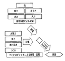
なお、本発明では電力量積算計を用いるため、一定時間毎の差分により電力消費量や、これに基づく排出量の計算を行うが、十分に詳細な電力流量計の値が利用できるのであれば、これの時間積分による計算を行ってもよい。ここで、実質的排出係数の一日の変化の単純化した一例を図2に示し、多彩なエネルギー源からのエネルギーをミックスする概念を図3に示す。
なお、本発明では電力量積算計を用いるため、一定時間毎の差分により電力消費量や、これに基づく排出量の計算を行うが、十分に詳細な電力流量計の値が利用できるのであれば、これの時間積分による計算を行ってもよい。ここで、実質的排出係数の一日の変化の単純化した一例を図2に示し、多彩なエネルギー源からのエネルギーをミックスする概念を図3に示す。
負荷、ないし下位系統に対しては、エネルギーミックス排出係数算出部104により排出係数を通知する。これは、Publish-Subscribeのような通信手段を用いてもよいし、WebService APIを用意して負荷、ないし下位系統からの問い合わせを待ってもよい。また、本発明の実施形態における排出係数算定器100が算出する排出係数の情報(排出係数情報)は、以下の項目を含むものである。
測定区間開始時刻:前回の測定時刻(式(1)におけるt-1)
測定区間終了時刻:今回の測定時刻(式(1)におけるt)
排出係数:時刻区間に対して算定された排出係数(式(1)におけるF(t))
なお、上位から得られる排出係数情報は、以上3項目を含むものであってもよい。その場合は、上位系統にある排出係数送信部は、問い合わせに対して直近の複数の区間の排出係数情報を返す機能を持つ。これは、下位側の計算において、区間がずれた場合の補償措置を行うことを可能とするためである。また、単純な(変化の少ない)上位系統における、排出係数の送信は、時刻区間を含まない単一の排出係数であってもよい。
測定区間開始時刻:前回の測定時刻(式(1)におけるt-1)
測定区間終了時刻:今回の測定時刻(式(1)におけるt)
排出係数:時刻区間に対して算定された排出係数(式(1)におけるF(t))
なお、上位から得られる排出係数情報は、以上3項目を含むものであってもよい。その場合は、上位系統にある排出係数送信部は、問い合わせに対して直近の複数の区間の排出係数情報を返す機能を持つ。これは、下位側の計算において、区間がずれた場合の補償措置を行うことを可能とするためである。また、単純な(変化の少ない)上位系統における、排出係数の送信は、時刻区間を含まない単一の排出係数であってもよい。
なお、排出係数はアカウンティング用途を除いては多少ずれても傾向が合っていれば利用価値を減じるものではないので、ここでは即時性を重視して上位の最新の排出係数を式(1)におけるFs(t)として利用する。一方、アカウンティングのための計算には、式(1)におけるFs(t)は、正しくその時刻区間に基づく計量を行った結果に基づいた排出係数を利用する必要がある。そのための方法については後の第3実施例で述べる。
なお、排出係数算定器動作開始時には、積算電力量の差分(ΔPs(t)およびΔPz(t))が計算できないため、F(t)の計算は、tがゼロから始まるとして、t=1のタイミングから行う。
以上の実施形態によれば、マイクログリッド機器を含めた電力ネットワークにおいて、刻々と変化するCO2排出係数を需要側にフィードバックすることにより、需給の不一致を解消できる。負荷側は、排出係数が低い時に電力を使うような制御を行うと、必然的にCO2排出量の削減と、過剰な電力の積極的な利用とを両立できる。
第1実施例:需要地系統における負荷制御への活用
本発明の実施形態として、需要地系統あるいはマイクログリッド機器に存在するゼロエミッション電源の利用において、本発明の実施形態による排出係数算定器により、電気自動車やエアコン、給湯器などといった調整可能負荷(電気の利用を一時的に停止しても住人の利便性に影響の出にくい負荷)を制御する事例を以下に示す。
本発明の実施形態として、需要地系統あるいはマイクログリッド機器に存在するゼロエミッション電源の利用において、本発明の実施形態による排出係数算定器により、電気自動車やエアコン、給湯器などといった調整可能負荷(電気の利用を一時的に停止しても住人の利便性に影響の出にくい負荷)を制御する事例を以下に示す。
以下では例として、図4を参照して、マイクログリッド機器を導入した家庭における空調制御を考える。空調制御は、設定温度にむけて気温を制御する。制御量に比例して電力が必要であるが、制御のタイミングや温度精度は厳格ではない。多少前後しても利用者が不快に感じることがある程度である。
そこで、マイクログリッド機器において、本発明の実施形態における排出係数算定器100を具備するマイクログリッド運用部401と、各戸に導入されたホームサーバ402とが通信を行い、負荷としてのエアコン403の運用を制御することを考える。本実施例では、マイクログリッド運用部401の排出係数算定器100がウェブサーバを持ち、特定URLにHTTPによりアクセスすることでその時点の実質排出係数を得られる、という簡単なモデルで考える。もちろん、Publish-Subscribe型を含む他の通信形態を用いてもよい。Publish-Subscribe型の通信形態を用いることで、CO2排出係数の変化量が一定の閾値(あるいは割合)を超えたときのみに通信を行うように制御する、などといった既知のPush型通信の利点を活用できる。
エアコン403は、ECHONET(登録商標)あるいは類似プロトコルにより制御が可能であるとする。ホームサーバ402とエアコン403の間の通信にはBluetooth(登録商標)などを用いる。また、ホームサーバはVDSL網などのローカルネットワークを用いて通信を行う。また、各戸に存在するホームサーバは自宅に接続されたマイクログリッド運用部401の排出係数算定器100のネットワークアドレス(この場合はアクセスのためのURL)を知っているものとする。
また、エアコン403には負荷調整機能を行うモード設定機能が存在するものとする。例えば、エコ運転モード、通常運転モード、加速運転モードのように識別するものとする。エコ運転モードは、通常よりも空調を弱くするモードである。夏ならばあまり冷やさず、冬ならば最低限の暖房で済ませる。エネルギー消費はもっとも少ない。通常運転モードは通常のとおりであり、加速運転モードは通常より高エネルギーを用いてより早く目標設定温度付近に到達させ、あるいは将来の省エネを考えて過剰に(夏はより涼しく、冬はより熱く)制御する。ただし、加速運転が継続しているときは、いちど過剰制御状態にした後は通常と同様の制御に戻してもよい。つまり、利用者が設定した温度目標値を超えた制御を行う状態は継続してもしなくてもよい。
例えばECHONETを想定すると、ECHONET CONSORTIUMより公開されているECHONET SPECIFICATION APPENDIX ECHONET機器オブジェクト詳細規定Version3.21Release bにおいては、節1.2.1において家庭用エアコンクラスの機器オブジェクト詳細が規定されている。ここで、急速動作モード設定という項目があり、通常運転/急速/静音の3つの排他的な動作モードが規定されている。同様に、エコ運転モードとして「エコ/通常/加速」の3モードを設定するプロパティを用意してもよいし、急速動作モード設定の解釈の範囲で同様の制御を行うよう規定しなおしてもよい。
さて、ここで、ホームサーバ402は以下のポリシで負荷を制御するとする。
・排出係数Fが閾値TLと等しいか、下回っていたら、稼働中のエアコンのエコ運転モードを「加速」にする
・排出係数Fが閾値TRに対してTR≧F>TLの範囲であれば、稼働中のエアコンのエコ運転モードを「通常」にする
・排出係数Fが閾値TRよりも高ければ、稼働中のエアコンのエコ運転モードを「エコ」にする
なお、以上のTR、TLについて、TR>TLである。
・排出係数Fが閾値TRに対してTR≧F>TLの範囲であれば、稼働中のエアコンのエコ運転モードを「通常」にする
・排出係数Fが閾値TRよりも高ければ、稼働中のエアコンのエコ運転モードを「エコ」にする
なお、以上のTR、TLについて、TR>TLである。
例えばTRを商用系統の電力に対して定数で適用する際の平均排出係数であるとすると、夜間など、比較的電力に余裕がある(平均よりも排出係数が低い)時は通常モードで、昼間など、火力発電所を稼動する必要がある時はエコ運転モードとなる。なお、接続されたマイクログリッド機器が十分にゼロエミッション発電するとFが低下するので、その低下の水準を想定してTLを決定する。
なお、マンション等、たくさんの住戸が接続されたマイクログリッド系統において、全戸が同じロジックで制御を行うと、電力がちょっと余り気味になると一斉に電力を使い、排出係数が悪化し、また一斉に電力消費を停止し、また電力を使う、というサイクルを繰り返す。そこで、一般的なロジックと同様にエコ運転モードの切り替え時にはランダムな待ち時間をおいて、待ち時間の間排出係数が閾値の条件をみたし続けた場合のみに切り替えを行う、といった保護ロジックを導入してもよい。
以上で述べたホームサーバの機能は、各負荷機器に搭載しても発明の本質は同じである。つまり、各負荷機器が排出係数算定器から排出係数を取得し、それに応じた動作を行う。
また、負荷制御について、単純な三段階ではなくより高い柔軟性を持つ負荷を持つ場合は、ここで述べたようなホームサーバ402による閾値判定ではなく、排出係数を直接読み取り、平均排出係数との比を求めることでどれだけの電力を使うかを決定してもよい。また、以上の事例では、マンション等におけるマイクログリッド機器と各戸のホームサーバ402および負荷から構成されるシステムにおける排出係数算定器の利用方法を示したが、これは事業所や工場などにおけるマイクログリッド機器と、各装置の制御盤と負荷から構成されるシステムにおいても同等のシステムを構築することで、同様の効果が発揮できる。
特に、調整可能負荷として、データセンタ等における計算負荷を考えることもできる。この場合、計算負荷と環境負荷(排出係数)との関係からサービス品質を決定することが考えられる。与えられたサービス品質を実現しうる物理計算機数を、仮想化による計算機台数制御やデータセンタ間での負荷のマイグレーションなどにより確保することにより、サービス品質と電力消費量のバランスを実現できる。
第2実施例:多層系統におけるCO2排出係数の算出
図5に、商用系統、地域などを管轄する中間系統、マンション内や事業所内に存在する需要家系統を経由して負荷が繋っている例を示す。この例では、商用系統が算出した排出係数情報を中間系統が利用し、中間系統におけるマイクログリッド機器が発電した電力の環境効率を、商用系統から受けた分と案分した排出係数情報を下位の需要家系統に渡している。
このように、上位-下位の関係において、上位で算定した排出係数を下位系統においてエネルギーソースの一つとして案分に用いることは、本発明の実施形態から考えて自然な拡張である。
図5に、商用系統、地域などを管轄する中間系統、マンション内や事業所内に存在する需要家系統を経由して負荷が繋っている例を示す。この例では、商用系統が算出した排出係数情報を中間系統が利用し、中間系統におけるマイクログリッド機器が発電した電力の環境効率を、商用系統から受けた分と案分した排出係数情報を下位の需要家系統に渡している。
このように、上位-下位の関係において、上位で算定した排出係数を下位系統においてエネルギーソースの一つとして案分に用いることは、本発明の実施形態から考えて自然な拡張である。
第3実施例:二酸化炭素排出量のアカウンティング
本発明の実施形態の一つとして、二酸化炭素排出量のアカウンティングへの応用がある。京都議定書などにより、二酸化炭素排出の削減が強く求められている一方、工場を除く事業所・店舗や、一般家庭への二酸化炭素排出量削減の取り組み状況は芳しくない。原因は多様であり、簡単に断じることはできないが、原因の一つには個々の負荷が小さいため、削減の取り組みの成果とコストが釣り合わないことがある。また、削減のインセンティブが得られづらい点も排出量削減の取り組みが進まない一因である。
本発明の実施形態の一つとして、二酸化炭素排出量のアカウンティングへの応用がある。京都議定書などにより、二酸化炭素排出の削減が強く求められている一方、工場を除く事業所・店舗や、一般家庭への二酸化炭素排出量削減の取り組み状況は芳しくない。原因は多様であり、簡単に断じることはできないが、原因の一つには個々の負荷が小さいため、削減の取り組みの成果とコストが釣り合わないことがある。また、削減のインセンティブが得られづらい点も排出量削減の取り組みが進まない一因である。
ここで、工場を除く事業所・店舗および一般家庭の二酸化炭素排出の多くが、電力により行われていることに注目し、電力による実質排出量を削減する取り組みを行う。そのための手段の一つとして、太陽電池等のゼロエミッションエネルギーを積極的に導入し、特に夏場の昼間のピークを抑えることで、電力消費を平滑化する。平滑化により、特に日本においては原子力発電の比率を高め、排出量を削減する効果がある。
ゼロエミッションエネルギーの効果的な導入には、二酸化炭素排出権取引への参加によるインセンティブの付与が有効であると考えられている。ここで、従来は消費電力量に対して、一つの定数である排出係数をかけることで、排出量を決定していたが、家庭あるいは事業所の、ピークが明確な利用パターンに対しては本発明による動的な排出係数により、実質的排出量を算出することで、ピークカットの効果が生み出せる。また、本発明の実施形態に固有の、排出係数を他の負荷の負荷制御のシグナルとする技術により、ピークカットによる排出権削減は、自動的に達成できる。
ここで、二酸化炭素排出量の算定方法について再度述べる。二酸化炭素排出量は、その時点での排出係数(kg/kWh)を、消費電力量(kWh)に乗じることによって算出できる。より厳密には時刻に対する排出係数と利用電力量に対して十分に正確な多項式近似を行い、これを積分することによって求める、などといった方法が考えられるが、その精度を求めるための測定やモデル化は困難である。そこで、本発明の実施形態においては、以下に述べる方法により排出量を求める。
まず、計量区間の同期を行う。別途導入する時刻同期機構(NTP:NetworkTime ProtocolやIEEE1588など、既知の手段を用いてもよい)により、時刻を同期させ、上位の系統の計量区間と、下位の系統の計量区間を高い精度で合わせる。
ゼロでない排出係数を持つ全ての電源(上位系統やガスを燃料とする燃料電池などを含む)について、計量区間に対応する排出係数を、計量区間内に消費された電力量に乗じる。これらを加算することで、その計量区間において排出した排出量が算定できる。なお、そのために、上位の系統の排出係数の算定が終了し、その結果を受信した後に下位の系統の排出量および排出係数を算定する必要がある。そのため、計量に用いる排出係数算定器のエネルギーミックス排出係数算出部は、次の2つの処理が個別に動作する。
1.上位系統と同期した一定時間毎に、上位系統からの受電量およびマイクログリッド機器内の各種電源機器の電力を測定し、対応するメモリを確保し、記録する。なお、この時上位排出係数は得られていないので、未算出を意味する値(本実施例ではマイナス1)を記入しておく。
2.上位系統の計算が終了するのを待ち、排出係数情報を受信し、該当するメモリの上位系統排出係数の項目に排出係数を記録すると同時に、式(1)に基づいた排出係数の計算を行い、メモリに記録する。
なお、この場合、エネルギーミックス排出係数算出部は、以下の構造を単位とする配列を構成する、メモリないしデータベースを持つ。配列は時系列に索引可能で、これに基づきΔPs(t)およびΔPz(t)を算出する(式(1))。
・測定区間終了時刻:測定時刻
・上位系統受電量:測定時刻における上位系統からの受電量積算値
・上位系統排出係数:上位系統において算出された排出係数(マイナスは未算出を意味する)
・ゼロエミッション発電量計測部:測定時刻におけるゼロエミッション発電量積算値
・排出係数:計量区間に対する、本系統における実質排出係数(マイナスは未算出を意味する)
・排出量:計量区間に対する、本系統以下における実質排出量
また、負荷ないし下位系統からの排出係数情報の問い合わせに関しては、排出係数の計算が完了している最新のメモリ構造と、その一つ前のメモリ構造から、排出係数情報を構成し、応答する。
・上位系統受電量:測定時刻における上位系統からの受電量積算値
・上位系統排出係数:上位系統において算出された排出係数(マイナスは未算出を意味する)
・ゼロエミッション発電量計測部:測定時刻におけるゼロエミッション発電量積算値
・排出係数:計量区間に対する、本系統における実質排出係数(マイナスは未算出を意味する)
・排出量:計量区間に対する、本系統以下における実質排出量
また、負荷ないし下位系統からの排出係数情報の問い合わせに関しては、排出係数の計算が完了している最新のメモリ構造と、その一つ前のメモリ構造から、排出係数情報を構成し、応答する。
ここで、排出量の算定から排出権取引の枠組に含めるために、以下の方式を提案する。実際にどの方式、あるいはこれに類似した方式になるとしても、本発明による実質的かつ自動的な排出係数の算出と、それに基づく負荷の制御は、マイクログリッド機器の導入効果を高める独創的な工夫である。
1.電力使用にかかるCO2排出量のベースラインは、電力系統の平均排出係数に総消費電力量を乗じた量であるもの:ベースライン・アンド・クレジット方式におけるベースライン量として、電力系統の平均排出係数(現在使われている排出係数)を全消費電力量に乗じたものを利用する。これにより、一般家庭に対して排出権と言う複雑な概念を適用することなく、マイクログリッド機器を導入した分それだけのクレジットが与えられ、マイクログリッド機器導入および利活用のインセンティブとなり得る。
2.電力の契約量から自動的に排出権割り当て(電力会社からの排出量移転)が行われるもの:キャップ・アンド・トレード方式により、自動的に排出権割り当てが行われるもの。電力契約量に応じて応分の負担を求める方式であり、より強い排出量削減効果を持つ可能性がある。一方で、エネルギー会社が顧客に排出権という制約を課すことに困難があると考えられるので、適切な制度設計が必要である。
また、第2実施例で述べたように、マイクログリッド機器が多層に存在する場合が考えられる。このとき、本発明の実施形態において算出できる排出量は、各階層の系統以下の全ての負荷の合計量となる。従って、多層に構成されている場合、排出量削減効果の算定を各層で行うと、効果を多重に算定してしまう。そこで、各階層における排出量の案分について、以下の方式を考える。
1.中間階層は、本発明による排出係数算定器を備える下位系統と、これを備えない下位系統を持つ。中間階層の排出量および排出権は、自身の排出量および排出権から排出係数算定器を備える下位系統の排出量および排出権の各々の合計を引いたものであるとする。これにより、中間階層におけるマイクログリッド機器導入による排出量削減効果は、排出係数算定器を備えない下位系統に対する削減効果の合計であるとする。
2.方式1に加えて、本発明の実施形態による排出係数算定器を備える下位系統において、中間階層のより上位から与えられた排出係数に基づく排出量算定と、中間階層のマイクログリッド機器の効果を含めた排出係数に基づく排出量算定を行い、この差分を中間階層の貢献として、下位の系統の排出権ないしクレジットから中間階層に移転するもの。
以上のいずれの方式、あるいは類似の方式を取ったとしても、本発明の実施形態における実質排出係数の算定機能と、これを多層に組み合わせた構成における実質排出量の計算機能は、本発明の実施形態に固有のエネルギーミックス排出係数算出部104の効果によるものである。
第4実施例:3つ以上のエネルギー源の取り扱い
以上の実施例では、簡単のため上位系統からの受電と、ゼロエミッション発電の2つのエネルギー源のみを考慮した。実際には、ガスタービンエンジンや燃料電池などを利用した熱・電力のミックス利用(コジェネ)が考えられている。この場合、熱による給湯を第一の目的とし、電力の供給を第二の目的とするならば、必要な量の給湯を行うことをもって副次的に供給された電力は、ゼロエミッションであると考えることもできる。一方で、ガスなどの燃料の消費は確かに二酸化炭素ガスの排出に繋がるので、これを計量し、熱利用効率や貯湯量から算出されるロス分を電力による排出分としてカウントする、などといった考え方もある。
以上の実施例では、簡単のため上位系統からの受電と、ゼロエミッション発電の2つのエネルギー源のみを考慮した。実際には、ガスタービンエンジンや燃料電池などを利用した熱・電力のミックス利用(コジェネ)が考えられている。この場合、熱による給湯を第一の目的とし、電力の供給を第二の目的とするならば、必要な量の給湯を行うことをもって副次的に供給された電力は、ゼロエミッションであると考えることもできる。一方で、ガスなどの燃料の消費は確かに二酸化炭素ガスの排出に繋がるので、これを計量し、熱利用効率や貯湯量から算出されるロス分を電力による排出分としてカウントする、などといった考え方もある。
後者の考え方のように、マイクログリッド機器電力に基づく温暖化ガス排出が発生する場合、排出係数算定器における算出式(実施形態における式(1))は、以下のように一般化する必要がある。
N個の電力源の時刻tにおける積算電力量をそれぞれPi(t)(ただしiは1からNまでの電力源識別番号)とし、それぞれの電力源の時刻区間t-1:tの排出係数をFi(t)とする。また、時刻区間t-1:tの電力消費量の合計を下記の式(2)で与えられるとする。
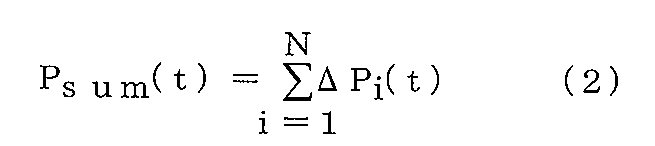
とする。ある系統における時刻区間t-1:tの実質排出係数F(t)は以下の式(3)により算出する。

第5実施例:充電池の取り扱い
SCiB(登録商標)のような、充電池あるいはキャパシタ(以下同等な機能を持つ構成要素を単に充電池と呼ぶ)をマイクログリッド機器に取り込むことを考える。充電池の存在により、電力量のタイムシフトが可能となる。冬季の短期的な晴れ間など、過剰に発電した電力を蓄え、雨や雪など暖房エネルギー需要が高まる時に放出することができる。このとき、充電池は負荷でもあり電力源でもある。
SCiB(登録商標)のような、充電池あるいはキャパシタ(以下同等な機能を持つ構成要素を単に充電池と呼ぶ)をマイクログリッド機器に取り込むことを考える。充電池の存在により、電力量のタイムシフトが可能となる。冬季の短期的な晴れ間など、過剰に発電した電力を蓄え、雨や雪など暖房エネルギー需要が高まる時に放出することができる。このとき、充電池は負荷でもあり電力源でもある。
以下、本発明の実施形態に基づく充電池の制御方法について述べた後、充電池の排出係数の算定方法について説明する。
充電池制御の基本的なアルゴリズムは短時間の揺動を抑えるために、できる範囲において容量の中央値を維持する、というものである。例えば電源周波数や電圧をモニタすることにより負荷のかかりかたをモニタし、過負荷(周波数の遅れあるいは電圧降下の発生)であるときには放電を開始し、負荷過少(周波数の進みあるいは電圧上昇)であるときには充電を行う。また、定期的に自動リフレッシュ動作(満充電→放電のサイクル)を行うものもある。ただし、これらはあくまで短期的な揺動に対応するためのものであるため、長期的には容量の中央値を維持するように制御する。具体的には、正常値(例えば電圧なら101V、周波数なら50HZあるいは60HZ)と許容振れ幅(例えば電圧ならプラスマイナス6V、周波数ならばプラスマイナス0.2HZ)に対して、容量中央値を中心点として、電圧・周波数の許容振れ幅いずれかまたはその合成について、容量ゼロから満充電までに割り振り、現在の電圧・周波数に対応する容量まで充放電を行う、といった方式が考えられる。つまり、容量cに対して、完全放電を0、満充電を1としたときに、例えば電圧vが与えられたときに充電すべきか放電すべきかは、以下の式(電圧充放電関数Cv(c,v))の正負によって求まる。
充電池制御の基本的なアルゴリズムは短時間の揺動を抑えるために、できる範囲において容量の中央値を維持する、というものである。例えば電源周波数や電圧をモニタすることにより負荷のかかりかたをモニタし、過負荷(周波数の遅れあるいは電圧降下の発生)であるときには放電を開始し、負荷過少(周波数の進みあるいは電圧上昇)であるときには充電を行う。また、定期的に自動リフレッシュ動作(満充電→放電のサイクル)を行うものもある。ただし、これらはあくまで短期的な揺動に対応するためのものであるため、長期的には容量の中央値を維持するように制御する。具体的には、正常値(例えば電圧なら101V、周波数なら50HZあるいは60HZ)と許容振れ幅(例えば電圧ならプラスマイナス6V、周波数ならばプラスマイナス0.2HZ)に対して、容量中央値を中心点として、電圧・周波数の許容振れ幅いずれかまたはその合成について、容量ゼロから満充電までに割り振り、現在の電圧・周波数に対応する容量まで充放電を行う、といった方式が考えられる。つまり、容量cに対して、完全放電を0、満充電を1としたときに、例えば電圧vが与えられたときに充電すべきか放電すべきかは、以下の式(電圧充放電関数Cv(c,v))の正負によって求まる。
Cv(c,v)=v-95+12・c
これが正のときに放電し、負のときに充電すればよい。ただし、当然、c≧1の時には充電せず、c≦0のときには放電できない。
これが正のときに放電し、負のときに充電すればよい。ただし、当然、c≧1の時には充電せず、c≦0のときには放電できない。
ここで、マイクログリッド機器に接続された電源機器の発電量に連動しつつ、様々な環境で動作する、排出量低減のための充電池制御の一般的アルゴリズムを説明する。本アルゴリズムは、本発明の実施形態における排出係数算定器を用いる。
簡単に考えて、マイクログリッド機器に接続された発電量が高いときには電力を蓄積し、マイクログリッド機器に接続された発電量が低いときには電力を放電すればよい。ただし、各マイクログリッド機器の性質や接続された機器の運転状況によって、発電量は異なる。そこで、本アルゴリズムでは、系統の電力品質、すなわち排出係数を用いる。
本アルゴリズムは、排出係数の過去の統計値を用いる方法である。今までの運転履歴から、排出係数の上位95%の値Fh、下位95%の値Flがわかるとする。特に、Fh>F>Flの条件において、現容量cと排出係数Fとの関係から充放電を制御する。例えば、図6において、斜線が引いてある領域であれば充電を行い、それ以外の領域であれば放電を行うなどである。このように、排出係数Fを用いて充放電を制御することで、二酸化炭素排出量を考慮した制御が可能になる。
本アルゴリズムの自然な拡張として、図6を変更し、より環境品質の良い電力のみを積極的に蓄えることや、環境悪化時のみに放電を行うよう変更することも考えられる。
本発明の実施形態で示したアルゴリズムであれ、他のアルゴリズムであれ、充電池に投入した電力の排出係数の正しい算定は、より良い運用アルゴリズムの普及を助ける。排出係数の算定においては、充電時の電力品質を案分して、さらにこれに充電ロス分を加味したものを電力品質とする。ただし、第3実施例で述べたアカウンティング用途においては、充電時に排出が終了したと見做すのが自然であるため、放電時の排出係数はゼロであるとする。
需要側制御に排出係数を用いる場合、充電池における、N回充電した後の電力の排出係数Fb(N)は、例えば次の漸化式ペアで求めることができる。ここでは、cp(i)をi+1番目の充電開始直前の充電率(0から1の実数)であるとする。i回目の充電における入力電力の排出係数(つまり、系統に接続された全ての電源の排出係数と電力量をもとに排出係数算定器が決定したもの)はFc(i)であり、その時の充電量に対応する充電率差分はcc(i)で表すものとする。また、放電時充電率差分d(i)は、i回目の充電後i+1回目の充電前の区間で放電される放電量を、充電率の低下分により表したものである。
Fb(0)=0
cp(0)=0
Fb(i+1)=(Fb(i)・cp(i)+Fc(i)・cc(i))/(cp(i)+cc(i))
cp(i+1)=cp(i)+cc(i)-d(i) (4)
なお、実際には、Fc(i)は計量区間内においてのみ有効であるため、計算上は一回の充電は計量区間内に終了させる必要がある。電気的に連続した充電であっても、式(4)による計算は、計量区間終了時に一旦行う。
cp(0)=0
Fb(i+1)=(Fb(i)・cp(i)+Fc(i)・cc(i))/(cp(i)+cc(i))
cp(i+1)=cp(i)+cc(i)-d(i) (4)
なお、実際には、Fc(i)は計量区間内においてのみ有効であるため、計算上は一回の充電は計量区間内に終了させる必要がある。電気的に連続した充電であっても、式(4)による計算は、計量区間終了時に一旦行う。
本発明の実施形態の排出係数算定器においては、電池排出係数算出部111と、電池充放電量計測部112を具備することにより、上記の計算を行う。電池排出係数算出部111においては、エネルギーミックス排出係数算出部104の計量区間に同期して式(4)の計算を行い、エネルギーミックス排出係数算出部104から得た排出係数Fc(i)などを用い、充放電に応じた内部メモリに蓄えたFb(i)およびcp(i)を更新する。電池充放電量計測部112は、式(4)のd(i)およびcc(i)を測定し、電池排出係数算出部111に渡す。
以上の構成により、変動する電力の環境品質を加味した充電池の排出係数算定が可能になる。
以上の構成により、変動する電力の環境品質を加味した充電池の排出係数算定が可能になる。
第6実施例:ゼロエミッショングリッド間連携による未来予想
太陽電池や風力発電などといった自然エネルギーの発電量は、近傍の時空間における発電量と強い相関があることが知られている。簡単に言えば、近所が晴れれば近い未来か過去に自分の居るところが晴れである可能性が高く、また近所に強い風が吹けば、同じく近い過去か未来に自分の居るところに強い風が吹く可能性が高い。
太陽電池や風力発電などといった自然エネルギーの発電量は、近傍の時空間における発電量と強い相関があることが知られている。簡単に言えば、近所が晴れれば近い未来か過去に自分の居るところが晴れである可能性が高く、また近所に強い風が吹けば、同じく近い過去か未来に自分の居るところに強い風が吹く可能性が高い。
この特性を用い、当該系統には属していない周辺にある近傍のゼロエミッション(ZE)発電の発電量を集め、既知の時空間相関分析手法を適用することで、自系統のZE発電の発電量と、近い過去(例えば5分前)の近傍のZE発電の発電量との相関モデルを求めることができる。
ここで、相関モデルが求まったとすると、現在の近傍のZE発電量から、近い将来の自身のZE発電量を、その信頼度と共に求めることができる。これを利用して、将来の排出係数を予測し、排出係数情報に付加する情報として排出係数予測情報を発信してもよい。図1においては、近傍ZE過去発電量実測値受信部115が、近傍に存在するZE発電量計測部から発電量の実測値を受信し、近傍ZE過去発電量実測値蓄積部116が過去の実測値を保管し、近傍ZE未来発電量推定部117が、時空間相関分析モデルを更新しつつ、近未来の発電量を予測し、エネルギーミックス排出係数予報部118が、式(1)におけるZE発電量ΔPzをZE発電量の推測値と置き換えると仮定して近未来のエネルギーミックス排出係数の推定値を算出する。
負荷あるいは下位系統は、現在の排出係数と将来の排出係数予報の差から、現在排出係数は上昇傾向にあるのか下降傾向にあるのかを把握し、負荷を作動させるべきタイミングを早めたり遅めたりできる。おおまかに言って、排出係数が上昇傾向にあるときは調整可能な負荷(空調など)は早めに使うのが合理的であり、また、排出係数が下降傾向にあるのであれば、遅めに使うのが合理的である。例えば、節3.1で述べたホームサーバのポリシにおいて、排出係数が上昇傾向であるか下降傾向であるか、それとも横這いかを判定して、それぞれにおいて異なるTRおよびTLを用いる、などといった方法が考えられる。
なお、本発明は上記実施形態そのままに限定されるものではなく、実施段階ではその要旨を逸脱しない範囲で構成要素を変形して具体化できる。また、上記実施形態に開示されている複数の構成要素の適宜な組み合わせにより、種々の発明を形成できる。例えば、実施形態に示される全構成要素から幾つかの構成要素を削除してもよい。さらに、異なる実施形態にわたる構成要素を適宜組み合わせてもよい。
100・・・排出係数算定器、101・・・上位系統排出係数受信部、102・・・上位系統受電量計測部、103・・・ゼロエミッション発電量計測部、104・・・エネルギーミックス排出係数算出部、111・・・電池排出係数算出部、112・・・電池充放電量計測部、113・・・燃料電池排出係数算出部、114・・・燃料電池発電量計測部、115・・・過去発電量実測値受信部、116・・・過去発電量実測値蓄積部、117・・・未来発電量推定部、118・・・エネルギーミックス排出係数予報部、401・・・マイクログリッド運用部、402・・・ホームサーバ、403・・・エアコン。
Claims (5)
- 上位系統における排出係数を一定時間ごとに受信する受信手段と、
上位系統からの受電した積算電力量を受電量として計測する受電量計測手段と、
当該系統におけるゼロエミッション電力によって発電した発電量を計測する発電量計測手段と、
前記受電量と前記発電量との比と上位系統の排出係数に応じて、当該系統の実質的排出係数を一定時間ごとに算出する排出係数算出手段と、を具備し、
前記排出係数算出手段は、負荷または下位系統に前記実質的排出係数を通知することを特徴とする排出係数算定器。 - 当該系統には属していない周辺にある、ゼロエミッションの発電量の実測値を受信する発電量受信手段と、
受信した前記発電量の実測値を蓄積する受信蓄積手段と、
前記発電量の実測値と前記発電量計測手段により計測した発電量との時空間相関から当該系統の未来のゼロエミッションによって発電すると想定される未来の電力量を推測する推測手段と、
前記未来の電力量に応じて、未来の実質的排出係数を算出する排出係数推定算出手段と、をさらに具備することを特徴とする請求項1に記載の排出係数算定器。 - 前記ゼロエミッション電力は充電池によるものであり、
前記ゼロエミッション電力は充電池によるものである場合には、前記排出係数算出手段は、該充電池の排出係数にも応じて、前記実質的排出係数を算出することを特徴とする請求項2に記載の排出係数算定器。 - 前記ゼロエミッション電力は燃料電池によるものであり、
前記ゼロエミッション電力は燃料電池によるものである場合には、前記排出係数算出手段は、該燃料電池の排出係数にも応じて、前記実質的排出係数を算出することを特徴とする請求項2に記載の排出係数算定器。 - 受信手段が上位系統における排出係数を一定時間ごとに受信するステップと、
受電量計測手段が上位系統からの受電した積算電力量を受電量として計測するステップと、
発電量計測手段が当該系統におけるゼロエミッション電力によって発電した発電量を計測するステップと、
排出係数算出手段が、前記受電量と前記発電量との比と上位系統の排出係数に応じて、当該系統の実質的排出係数を一定時間ごとに算出するステップと、
前記排出係数算出手段が負荷または下位系統に前記実質的排出係数を通知するステップを含むことを特徴とする排出係数算定方法。
Priority Applications (2)
| Application Number | Priority Date | Filing Date | Title |
|---|---|---|---|
| CN201080009427.8A CN102334037B (zh) | 2009-02-27 | 2010-02-26 | 排放系数计算器与排放系数计算方法 |
| US13/217,934 US8880355B2 (en) | 2009-02-27 | 2011-08-25 | Emission factor calculating apparatus and emission factor calculating method |
Applications Claiming Priority (2)
| Application Number | Priority Date | Filing Date | Title |
|---|---|---|---|
| JP2009045932A JP5355147B2 (ja) | 2009-02-27 | 2009-02-27 | 排出係数算定器および排出係数算定方法 |
| JP2009-045932 | 2009-02-27 |
Related Child Applications (1)
| Application Number | Title | Priority Date | Filing Date |
|---|---|---|---|
| US13/217,934 Continuation US8880355B2 (en) | 2009-02-27 | 2011-08-25 | Emission factor calculating apparatus and emission factor calculating method |
Publications (1)
| Publication Number | Publication Date |
|---|---|
| WO2010098455A1 true WO2010098455A1 (ja) | 2010-09-02 |
Family
ID=42665659
Family Applications (1)
| Application Number | Title | Priority Date | Filing Date |
|---|---|---|---|
| PCT/JP2010/053128 Ceased WO2010098455A1 (ja) | 2009-02-27 | 2010-02-26 | 排出係数算定器および排出係数算定方法 |
Country Status (4)
| Country | Link |
|---|---|
| US (1) | US8880355B2 (ja) |
| JP (1) | JP5355147B2 (ja) |
| CN (1) | CN102334037B (ja) |
| WO (1) | WO2010098455A1 (ja) |
Cited By (5)
| Publication number | Priority date | Publication date | Assignee | Title |
|---|---|---|---|---|
| CN102545203A (zh) * | 2010-09-30 | 2012-07-04 | 株式会社东芝 | 用户能源管理系统 |
| JP2012135121A (ja) * | 2010-12-22 | 2012-07-12 | Chubu Electric Power Co Inc | 逆潮流想定方法 |
| JP7369494B1 (ja) | 2023-05-08 | 2023-10-26 | 株式会社電力シェアリング | 環境価値評価システム、環境価値評価方法、及び環境価値評価プログラム |
| CN116955916A (zh) * | 2023-09-19 | 2023-10-27 | 中汽研汽车检验中心(武汉)有限公司 | 一种轻型车蒸发排放总量计算方法 |
| US12141820B2 (en) * | 2023-02-09 | 2024-11-12 | Peak Power, Inc. | Greenhouse gas emissions control based on marginal emission factor data and energy storage systems |
Families Citing this family (20)
| Publication number | Priority date | Publication date | Assignee | Title |
|---|---|---|---|---|
| WO2011118607A1 (ja) * | 2010-03-24 | 2011-09-29 | 三洋電機株式会社 | 電力供給装置、蓄電装置並びに電力制御装置 |
| US20130015703A1 (en) * | 2011-07-16 | 2013-01-17 | Rouse Gregory C | Microgrid |
| JP2013090485A (ja) * | 2011-10-19 | 2013-05-13 | Hitachi Ltd | Co2排出量監視装置、co2排出量監視方法、co2排出量監視プログラム、およびco2排出量監視システム |
| JP5843572B2 (ja) * | 2011-11-10 | 2016-01-13 | 株式会社東芝 | 運転計画システム及び運転計画作成方法 |
| WO2013086411A1 (en) * | 2011-12-09 | 2013-06-13 | The Aes Corporation | Frequency responsive charge sustaining control of electricity storage systems for ancillary services on an electrical power grid |
| CN103530701B (zh) * | 2013-10-12 | 2016-06-22 | 国家电网公司 | 一种基于季节指数法的用户月用电量预测方法和系统 |
| JP2016040007A (ja) * | 2015-12-22 | 2016-03-24 | 大阪瓦斯株式会社 | ミストサウナ装置 |
| JP2018163542A (ja) * | 2017-03-27 | 2018-10-18 | 日本電気株式会社 | 予測装置、予測システム、予測方法、および予測プログラム |
| CN111855901A (zh) * | 2020-06-27 | 2020-10-30 | 同济大学 | 一种基于功率排放因子的船舶排放测试方法 |
| EP3937112A1 (en) * | 2020-07-06 | 2022-01-12 | Karl Kull | Method for energy consumption management based on the principle of primary energy share in the system |
| US11694258B2 (en) | 2020-10-19 | 2023-07-04 | Tergo, Llc | Systems, methods, and devices for generating and trading environmental credits |
| TWI776596B (zh) * | 2021-07-15 | 2022-09-01 | 逢甲大學 | 整合智慧製造與碳排放最佳化決策資訊管理系統 |
| CN114202114A (zh) * | 2021-12-01 | 2022-03-18 | 新奥数能科技有限公司 | 一种分布式光伏电站的结算数据获取方法及装置 |
| CN114548562B (zh) * | 2022-02-24 | 2025-12-19 | 清华大学 | 基于碳排放流的碳排放响应计算方法及装置 |
| CN115593420B (zh) * | 2022-09-29 | 2024-04-12 | 南京领行科技股份有限公司 | 一种碳减排量确定方法、装置、电子设备及存储介质 |
| CN116227822B (zh) * | 2022-12-20 | 2025-12-12 | 国网福建省电力有限公司 | 一种基于省级电网边际排放因子的电网规划方法及终端 |
| JP2024099201A (ja) * | 2023-01-12 | 2024-07-25 | トヨタ自動車株式会社 | 電力網の管理システム |
| US20240313534A1 (en) * | 2023-03-17 | 2024-09-19 | Enersponse Inc | System and method for automated adjustment of energy usage |
| CN116823295B (zh) * | 2023-08-31 | 2024-04-19 | 国网山东省电力公司营销服务中心(计量中心) | 一种钢铁行业碳排放测量方法、系统、设备及介质 |
| CN119739761B (zh) * | 2024-12-10 | 2025-08-22 | 图迹科技有限公司 | 基于InfluxDB的储能系统累计电量差值计算方法和装置 |
Citations (3)
| Publication number | Priority date | Publication date | Assignee | Title |
|---|---|---|---|---|
| JP2004138516A (ja) * | 2002-10-18 | 2004-05-13 | Yokogawa Electric Corp | 電力測定装置 |
| JP2007037226A (ja) * | 2005-07-25 | 2007-02-08 | Mitsubishi Electric Corp | 電源システムおよびその制御方法 |
| JP2008009489A (ja) * | 2006-06-27 | 2008-01-17 | Chugoku Electric Power Co Inc:The | 環境管理システム |
Family Cites Families (12)
| Publication number | Priority date | Publication date | Assignee | Title |
|---|---|---|---|---|
| JP2731953B2 (ja) * | 1989-08-07 | 1998-03-25 | キヤノン株式会社 | エネルギー量制御装置 |
| JP2001332463A (ja) * | 2000-05-24 | 2001-11-30 | Tokyo Electron Ltd | 半導体製造に用いられる装置の管理装置及びその管理方法 |
| US20030229572A1 (en) * | 2001-12-28 | 2003-12-11 | Icf Consulting | Measurement and verification protocol for tradable residential emissions reductions |
| JP3783859B2 (ja) * | 2002-07-19 | 2006-06-07 | 日立プラント建設株式会社 | 空調設備及びその制御方法 |
| US7343341B2 (en) * | 2002-07-20 | 2008-03-11 | Chicago Climate Exchange, Inc. | Systems and methods for trading emission reductions |
| US8000938B2 (en) * | 2002-12-09 | 2011-08-16 | Verisae, Inc. | Method and system for tracking and managing destruction, reconstitution, or reclamation of regulated substances |
| US7877235B2 (en) * | 2003-01-31 | 2011-01-25 | Verisae, Inc. | Method and system for tracking and managing various operating parameters of enterprise assets |
| US8615381B2 (en) * | 2005-11-15 | 2013-12-24 | Robert Bosch Healthcare Systems, Inc. | Home power management system |
| JP2008097303A (ja) | 2006-10-11 | 2008-04-24 | Chugoku Electric Power Co Inc:The | Co2排出量表示装置 |
| JP2008192103A (ja) * | 2007-02-08 | 2008-08-21 | Yokogawa Electric Corp | 二酸化炭素排出量算出システムおよび二酸化炭素排出量算出方法 |
| JP2008243110A (ja) * | 2007-03-29 | 2008-10-09 | Hitachi Ltd | 燃料環境影響物排出量評価システム |
| US20100191998A1 (en) * | 2009-01-23 | 2010-07-29 | Microsoft Corporation | Apportioning and reducing data center environmental impacts, including a carbon footprint |
-
2009
- 2009-02-27 JP JP2009045932A patent/JP5355147B2/ja active Active
-
2010
- 2010-02-26 CN CN201080009427.8A patent/CN102334037B/zh not_active Expired - Fee Related
- 2010-02-26 WO PCT/JP2010/053128 patent/WO2010098455A1/ja not_active Ceased
-
2011
- 2011-08-25 US US13/217,934 patent/US8880355B2/en not_active Expired - Fee Related
Patent Citations (3)
| Publication number | Priority date | Publication date | Assignee | Title |
|---|---|---|---|---|
| JP2004138516A (ja) * | 2002-10-18 | 2004-05-13 | Yokogawa Electric Corp | 電力測定装置 |
| JP2007037226A (ja) * | 2005-07-25 | 2007-02-08 | Mitsubishi Electric Corp | 電源システムおよびその制御方法 |
| JP2008009489A (ja) * | 2006-06-27 | 2008-01-17 | Chugoku Electric Power Co Inc:The | 環境管理システム |
Cited By (7)
| Publication number | Priority date | Publication date | Assignee | Title |
|---|---|---|---|---|
| CN102545203A (zh) * | 2010-09-30 | 2012-07-04 | 株式会社东芝 | 用户能源管理系统 |
| JP2012135121A (ja) * | 2010-12-22 | 2012-07-12 | Chubu Electric Power Co Inc | 逆潮流想定方法 |
| US12141820B2 (en) * | 2023-02-09 | 2024-11-12 | Peak Power, Inc. | Greenhouse gas emissions control based on marginal emission factor data and energy storage systems |
| JP7369494B1 (ja) | 2023-05-08 | 2023-10-26 | 株式会社電力シェアリング | 環境価値評価システム、環境価値評価方法、及び環境価値評価プログラム |
| JP2024161843A (ja) * | 2023-05-08 | 2024-11-20 | 株式会社電力シェアリング | 環境価値評価システム、環境価値評価方法、及び環境価値評価プログラム |
| CN116955916A (zh) * | 2023-09-19 | 2023-10-27 | 中汽研汽车检验中心(武汉)有限公司 | 一种轻型车蒸发排放总量计算方法 |
| CN116955916B (zh) * | 2023-09-19 | 2023-12-26 | 中汽研汽车检验中心(武汉)有限公司 | 一种轻型车蒸发排放总量计算方法 |
Also Published As
| Publication number | Publication date |
|---|---|
| US20120053848A1 (en) | 2012-03-01 |
| CN102334037B (zh) | 2014-07-02 |
| US8880355B2 (en) | 2014-11-04 |
| JP2010197355A (ja) | 2010-09-09 |
| JP5355147B2 (ja) | 2013-11-27 |
| CN102334037A (zh) | 2012-01-25 |
Similar Documents
| Publication | Publication Date | Title |
|---|---|---|
| JP5355147B2 (ja) | 排出係数算定器および排出係数算定方法 | |
| CN107851994B (zh) | 电力供需预测系统、方法及计算机可读存储介质 | |
| CN107103401B (zh) | 控制配电网络中的电能消耗的方法和节点 | |
| Zhu et al. | Sharing renewable energy in smart microgrids | |
| CN102436602B (zh) | 能量管理系统以及能量管理方法 | |
| JP4938750B2 (ja) | 消費電力予測装置、消費電力予測方法およびプログラム | |
| EP2953230A1 (en) | Energy management system, energy management method, program and server | |
| Rajasekharan et al. | Optimal energy consumption model for smart grid households with energy storage | |
| JPWO2017217466A1 (ja) | 電力管理システム | |
| JP7297004B2 (ja) | 電力供給システム及び、電力管理方法 | |
| JP5645442B2 (ja) | 電力需要管理システムおよび電力需要管理方法 | |
| WO2014034391A1 (ja) | エネルギー管理システム、サーバ、エネルギー管理方法および記憶媒体 | |
| Wu et al. | Impact of model predictive control-enabled home energy management on large-scale distribution systems with photovoltaics | |
| JP2014176161A (ja) | エネルギー管理システム、エネルギー管理方法、プログラムおよびサーバ | |
| JP5622924B2 (ja) | 電力需要管理システム及び電力需要管理方法 | |
| JP2017229233A (ja) | エネルギー管理システム、エネルギー管理方法、プログラム、サーバおよびクライアント装置 | |
| Oviedo et al. | A residential PHEV load coordination mechanism with renewable sources in smart grids | |
| Ghorbani et al. | Multi-agent autonomous decision making in smart micro-grids’ energy management: a decentralized approach | |
| JP5484621B1 (ja) | 蓄電装置の放電開始時刻決定システム | |
| Fattaheian-Dehkordi et al. | Incentive-based flexible-ramp-up management in multi-microgrid distribution systems | |
| Hao et al. | Locational marginal pricing in the campus power system at the power distribution level | |
| JP2016046922A (ja) | 電力需給調整システム、上位地域電力管理装置、および、下位地域電力管理装置 | |
| Xue et al. | Interactive building load management for smart grid | |
| JPWO2019182016A1 (ja) | 電力情報管理システム、管理方法、プログラム、電力情報管理サーバ、通信端末、及び、電力システム | |
| Yaghmaee et al. | Power consumption scheduling for future connected smart homes using bi-level cost-wise optimization approach |
Legal Events
| Date | Code | Title | Description |
|---|---|---|---|
| WWE | Wipo information: entry into national phase |
Ref document number: 201080009427.8 Country of ref document: CN |
|
| 121 | Ep: the epo has been informed by wipo that ep was designated in this application |
Ref document number: 10746334 Country of ref document: EP Kind code of ref document: A1 |
|
| NENP | Non-entry into the national phase |
Ref country code: DE |
|
| 122 | Ep: pct application non-entry in european phase |
Ref document number: 10746334 Country of ref document: EP Kind code of ref document: A1 |