WO2010090182A1 - Système de commutation d'application et procédé de commutation d'application - Google Patents
Système de commutation d'application et procédé de commutation d'application Download PDFInfo
- Publication number
- WO2010090182A1 WO2010090182A1 PCT/JP2010/051424 JP2010051424W WO2010090182A1 WO 2010090182 A1 WO2010090182 A1 WO 2010090182A1 JP 2010051424 W JP2010051424 W JP 2010051424W WO 2010090182 A1 WO2010090182 A1 WO 2010090182A1
- Authority
- WO
- WIPO (PCT)
- Prior art keywords
- relay device
- relay
- server
- controller
- switch
- Prior art date
Links
Images


Classifications
-
- H—ELECTRICITY
- H04—ELECTRIC COMMUNICATION TECHNIQUE
- H04W—WIRELESS COMMUNICATION NETWORKS
- H04W40/00—Communication routing or communication path finding
- H04W40/02—Communication route or path selection, e.g. power-based or shortest path routing
- H04W40/22—Communication route or path selection, e.g. power-based or shortest path routing using selective relaying for reaching a BTS [Base Transceiver Station] or an access point
-
- H—ELECTRICITY
- H04—ELECTRIC COMMUNICATION TECHNIQUE
- H04L—TRANSMISSION OF DIGITAL INFORMATION, e.g. TELEGRAPHIC COMMUNICATION
- H04L45/00—Routing or path finding of packets in data switching networks
- H04L45/42—Centralised routing
-
- H—ELECTRICITY
- H04—ELECTRIC COMMUNICATION TECHNIQUE
- H04L—TRANSMISSION OF DIGITAL INFORMATION, e.g. TELEGRAPHIC COMMUNICATION
- H04L67/00—Network arrangements or protocols for supporting network services or applications
- H04L67/50—Network services
- H04L67/56—Provisioning of proxy services
- H04L67/563—Data redirection of data network streams
-
- H—ELECTRICITY
- H04—ELECTRIC COMMUNICATION TECHNIQUE
- H04L—TRANSMISSION OF DIGITAL INFORMATION, e.g. TELEGRAPHIC COMMUNICATION
- H04L69/00—Network arrangements, protocols or services independent of the application payload and not provided for in the other groups of this subclass
- H04L69/16—Implementation or adaptation of Internet protocol [IP], of transmission control protocol [TCP] or of user datagram protocol [UDP]
- H04L69/161—Implementation details of TCP/IP or UDP/IP stack architecture; Specification of modified or new header fields
-
- H—ELECTRICITY
- H04—ELECTRIC COMMUNICATION TECHNIQUE
- H04L—TRANSMISSION OF DIGITAL INFORMATION, e.g. TELEGRAPHIC COMMUNICATION
- H04L69/00—Network arrangements, protocols or services independent of the application payload and not provided for in the other groups of this subclass
- H04L69/16—Implementation or adaptation of Internet protocol [IP], of transmission control protocol [TCP] or of user datagram protocol [UDP]
- H04L69/163—In-band adaptation of TCP data exchange; In-band control procedures
-
- H—ELECTRICITY
- H04—ELECTRIC COMMUNICATION TECHNIQUE
- H04L—TRANSMISSION OF DIGITAL INFORMATION, e.g. TELEGRAPHIC COMMUNICATION
- H04L67/00—Network arrangements or protocols for supporting network services or applications
- H04L67/01—Protocols
- H04L67/10—Protocols in which an application is distributed across nodes in the network
- H04L67/1001—Protocols in which an application is distributed across nodes in the network for accessing one among a plurality of replicated servers
- H04L67/1038—Load balancing arrangements to avoid a single path through a load balancer
Definitions
- the present invention relates to an application switch system, and more particularly to an application switch system that performs network path control.
- Patent Document 1 discloses a method for relaying two TCP sessions called TCP (Transmission Control Protocol) splicing.
- TCP splicing is a high-speed processing method of a TCP proxy device such as an application gateway, and is a method of shortcuting two TCP sessions for performing TCP proxy to packet-level relay processing.
- Patent Document 2 (US Patent No. 7000027) is based on another form of TCP splicing.
- Patent Document 2 discloses a method in which one of the back-end nodes performs TCP termination processing, interprets an application-level request, determines which back-end node the processing is allocated, and hands off to that node. Has been.
- An application that performs proxy processing is running on the back-end node, and describes a distributed processing method for determination of processing allocation at the back-end node and TCP splicing processing at the front-end node.
- TCP splicing as shown in Patent Document 1 is used in a relay device called an application switch.
- TCP termination processing is performed on the first TCP session with the client, and the next node is determined after interpreting the application level message.
- HTTP Hyper Text Transfer Protocol
- the request message from the client to the server after establishing TCP is interpreted to determine what resource access request is requested, and the actual back-end server To switch to and load balance processing.
- a second TCP session is established with the back-end server, and the first TCP session and the second TCP session with the client are relayed at the packet level.
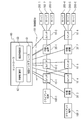
- FIG. 1 shows a conventional system that performs server load balancing processing using an application switch.
- client terminals 100-1 to 100-2 are shown as client terminals 100.
- switches 10-1 to 10-3 are shown.
- servers 200-1 to 200-6 are shown.
- the servers 200-1 to 200-3 are connected to the application switch 20, and the servers 200-4 to 200-6 are connected to the switch 10-3.
- the application switch 20 interprets an application layer message, and the server 200 A server to be actually accessed is selected from -1 to 200-6, and relay connection is performed.
- the servers 200-1 to 200-3 are typically provided near the application switch 20 (on the application switch side). When any one of 200-1 to 200-3 is selected, the network traffic (communication amount) does not become inefficient.
- VM Virtual Machine
- the network path is the switch 10-1, the application switch 20, The switch 10-1, the switch 10-2, the switch 10-3, and the server 200-6.
- the conventional system as shown in FIG. 1 has a problem that the network path becomes inefficient when the switch process is performed using the application switch.
- Patent Document 2 is a distribution splicing unit in an application switch deployed in a back-end node in TCP splicing processing. Thereby, it is possible to distribute the load of determination processing in the application switch.
- this method there is a problem that the front-end processing for performing TCP splicing needs to be on a route to a plurality of back-end nodes, and relay processing becomes inefficient when servers are distributed over a wide area.
- An object of the present invention is to provide a method for efficiently performing application relay processing, and when an object to be distributed by an application switch is distributed over a wide area, an optimum relay node is selected without going through a single relay node. And providing efficient network accommodation.
- the application switch system of the present invention includes a switch that controls connection between a plurality of client terminals and a plurality of servers existing on the network, a relay device that performs protocol relay, and a controller.
- the controller includes means for centrally controlling a routing table for determining a transfer destination in the switch, means for controlling relay processing of the relay device, means for selecting a server to be a connection destination among a plurality of servers, Means for connecting a client of one of the client terminals and the selected server, selecting a route including the relay device, and setting the selected route in the route table in the switch, and the relay device relaying the protocol Means for setting the relay information used in performing the relay to the relay device.
- another application switch system of the present invention includes a switch that controls connection between a plurality of client terminals and a plurality of servers existing on a network, a relay device that performs protocol relay, and a controller.
- a controller for centrally controlling a routing table for determining a transfer destination in the switch; means for controlling relay processing of a relay device; and means for determining a server group that is a candidate for a connection destination among a plurality of servers; Selecting a relay device that connects a client of a plurality of client terminals and each connection destination candidate server and performs a relay process to a plurality of server groups, and selects a route including the relay device.
- the switch controls the connection between a plurality of client terminals and a plurality of servers existing on the network.
- protocol relay is performed by the relay device.
- the controller centrally controls the route table for determining the transfer destination in the switch.
- the relay process of the relay device is controlled by the controller.
- the server selects a connection destination server from among the plurality of servers.
- the controller connects one client of the plurality of client terminals and the selected server, and selects a route including the relay device.
- the selected route is set in the route table in the switch by the controller.
- the relay information used when the relay device performs protocol relay is set in the relay device by the controller.
- the computer performs the following operations by executing the program according to the present invention.
- the computer causes a plurality of servers, switches, and relay devices to operate as virtual machine applications on the computer.
- the switch controls connections between a plurality of client terminals and a plurality of servers existing on the network.
- protocol relay is performed by the relay device.
- centralized control is performed on a route table for determining a transfer destination in the switch. It also controls relay processing of the relay device.
- a server to be a connection destination among a plurality of servers is selected.
- a route including one of the plurality of client terminals is connected to the selected server and the relay device is selected. The selected route is set in the route table in the switch.
- relay information used when the relay device performs protocol relay is set in the relay device.
- the program according to the present invention can be stored in a storage medium or a storage device.
- FIG. 10 is a sequence diagram illustrating an operation of the application switch system in the third embodiment.
- a relay device 30, a control line 50, a controller 60, and a server 200 (200-i, i 1 to N).
- the client terminal 100 is connected to the server 200 via the switch 10 and the relay device 30.
- the switch 10 and the relay device 30 exist on the network.
- the numbers of the client terminal 100, the switch 10, the relay device 30, and the server 200 are different.
- the numbers of the client terminal 100, the switch 10, the relay device 30, and the server 200 may be the same.
- Switch 10 is an application switch.
- the relay device 30 relays transfer data between the client terminal 100 and the server 200 by TCP (Transmission Control Protocol) splicing processing.
- TCP Transmission Control Protocol
- the controller 60 is connected to the switch 10 and the relay device 30 via the control line 50, and centrally manages the switch 10 and the relay device 30.
- the controller 60 includes a control interface 61, a relay control unit 62, and a route control unit 63.
- the control interface 61 is connected to the switch 10 and the relay device 30 via the control line 50.
- the relay control unit 62 performs application distribution determination. Further, the relay control unit 62 performs control (relay control) on the relay device 30. Here, the relay control unit 62 performs handoff processing on the relay device 30. For example, the relay control unit 62 instructs the relay device 30 to start relaying. The relay device 30 starts relay processing in response to the relay start instruction.
- the route control unit 63 centrally manages network routes. Further, the path control unit 63 calculates a path from the connection source client terminal 100 to the server 200 and selects one of the relay apparatuses 30 on the path. Here, after the relay control unit 62 determines the application distribution destination, the path control unit 63 selects the relay device 30 closest to the distribution destination server and sets a route to the selected relay device 30.
- the controller 60 optimizes the network path by selecting a distribution to an arbitrary server distributed in a wide area, selecting an optimal network path at that time, and selecting a relay position.
- Examples of the client terminal 100 include a PC (personal computer), a mobile notebook PC, a thin client terminal, a workstation, a mobile phone, a car navigation system (car navigation system), a portable game machine, a home game machine, an interactive TV, a digital tuner, a digital A recorder, an information home appliance, an OA (Office Automation) device, etc. can be considered.
- the client terminal 100 may be mounted on a moving body such as a vehicle, a ship, or an aircraft. However, actually, it is not limited to these examples.
- Examples of the communication line on the network to which the switch 10 and the relay device 30 belong, and the control line 50 include the Internet, a LAN (Local Area Network), a wireless LAN (Wireless LAN), a WAN (Wide Area Network), a backbone (Backbone), Cable TV (CATV) line, fixed telephone network, mobile phone network, WiMAX (IEEE 802.16a), 3G (3rd Generation), dedicated line (lease line), IrDA (Infrared Data Association), Bluetooth (registered trademark), serial A communication line, a data bus, etc. can be considered. However, actually, it is not limited to these examples.
- a computer such as a PC (personal computer), a thin client server, a workstation, a mainframe, and a supercomputer can be considered. However, actually, it is not limited to these examples.
- each device at the time of connection connection from the client terminal 100 to the server 200 will be described by taking as an example a case where the client terminal 100-1 connects to a predetermined service in the application switch system as shown in FIG. .
- the client terminal 100-1 makes a TCP connection request to the controller 60.
- the client terminal 100-1 transmits a packet destined for the controller 60 and attempts TCP connection.
- the controller 60 appears to the server 200 when viewed from the terminal 100-1. That is, the terminal 100-1 regards the controller 60 as the server 200.
- the switch 10-1 When the switch 10-1 receives the packet transmitted from the client terminal 100-1, the switch 10-1 performs a transfer process based on the flow entry of the switch 10.
- the switch 10-1 sends the packet transmitted from the client terminal 100-1 to the controller 60 through the control line 50.
- the controller 60 processes the TCP connection request from the client terminal 100-1 using the TCP protocol stack.
- the controller 60 also transmits the packet addressed to the client terminal 100-1 via the switch 10-1.
- the controller 60 selects the server 200 to be connected (accessed) based on the content of the transmission data from the client terminal 100-1.
- the selection determination there are a method of smoothing the load of the server 200, a method of selecting an item close to the client terminal 100-1, and the like.
- the controller 60 After the controller 60 selects the server 200, the controller 60 connects the second TCP connection between the controller 60 and the server 200.
- the controller 60 selects the relay device 30 on the route between the client terminal 100-1 and the server 200 or the relay device 30 located near the route, and the first TCP information and the second TCP information. To perform the splicing process. As a result, the access process between the client terminal 100-1 and the server 200 changes from the proxy process via the controller 60 to the packet relay process via the relay process.
- the switch processing unit 11 extracts the header information of the packet input from the line 14 and refers to the flow table 12 to determine the output line.
- the switch processing unit 11 connects to the client terminal 100, another switch 10, the relay device 30, and the server 200 via the line 14.
- the flow table 12 has an entry for registering information obtained from a MAC (Media Access Control) header, an IP (Internet Protocol) header, and a layer 4 header as flow identification information and storing output information for the flow.
- MAC Media Access Control
- IP Internet Protocol
- the flow table 12 may be based on a flow identifier such as flow information specified by an IP address and a TCP port number, and other labels.
- the switch control unit 13 is connected to the controller 60 via the control interface 61. At this time, the switch control unit 13 is connected to the control interface 61 via the control line 50. That is, the switch control unit 13 receives instructions, operations, and other data from the controller 60 via the control line 50. Here, the switch control unit 13 performs control communication with the controller 60 and controls the inside of the switch 10. The controller 60 performs control such as registration and deletion of the flow entry via the switch control unit 13. Further, the switch control unit 13 transmits a packet that does not hit the flow entry to the controller 60 via the control interface, or performs a transmission process to a designated output line by a packet transmission command from the controller 60.
- the relay device 30 includes a TCP header conversion processing unit 31, a conversion table 32, a relay protocol processing unit 33, a line 34, and a line 35.
- the TCP header conversion processing unit 31 is connected to the outside via the line 34 and the line 35.
- the TCP header conversion processing unit 31 is connected to the client terminal 100, another switch 10, the relay device 30, and the server 200 via the line 34 and the line 35.
- the TCP header conversion processing unit 31 performs TCP header conversion processing on packets transmitted and received between the line 34 and the line 35 based on the conversion table 32.
- the TCP header conversion processing unit 31 refers to the conversion table 32 for the packet received from the line 34 or 35 and the header of the received packet hits the header described in the conversion table 32. Performs header conversion processing to replace the header of the received packet with the header described in the conversion table 32.
- the conversion table 32 describes information necessary for the TCP splicing process.
- the conversion table 32 has an input key, output information, and state information as entries.
- the TCP header conversion processing unit 31 refers to the conversion table 32, searches using the IP address and TCP port number as input keys, rewrites the IP address and TCP port number, and a correction value for recalculating the sequence number. To get.
- the relay protocol processing unit 33 is connected to the controller 60 via the control interface 61. At this time, the relay protocol processing unit 33 is connected to the control interface 61 via the control line 50. That is, the relay protocol processing unit 33 receives instructions, operations, and other data from the controller 60 via the control line 50.
- the relay protocol processing unit 33 performs protocol processing related to relay control such as a handoff request command from the controller 60 and a relay start instruction.
- the relay protocol processing unit 33 sets the conversion table 32 necessary for the TCP splicing process in accordance with the handoff command. Further, the relay protocol processing unit 33 validates the splicing process for the corresponding flow in accordance with the relay start instruction and transmits the packet held in the buffer.
- the lines 34 and 35 are communication lines connected to the client terminal 100, the other switch 10, the relay device 30, the server 200, and the like.
- the relay device 30 may also have a switching function.
- a device having a relay processing function according to the present invention is specifically referred to as a relay device 30, and a line switch not having the relay processing function is referred to as a switch 10.
- the switch 10 and the relay device 30 are distinguished.
- the conversion table 32 includes, as input keys, a line number, an IP destination address (IPDA: IP Destination Address), an IP source address (IPSA), and a TCP source port number (TCPSP: TCP Source Port). And a TCP destination port number (TCPDP: TCP Destination Port).
- IPDA IP Destination Address
- IP source address IP source address
- TCP destination port number TCP Destination Port
- the TCP header conversion processing unit 31 refers to the conversion table 32 and determines whether or not there is an entry by checking the header of the received packet with these input keys.
- the conversion table 32 includes, as output information, an output line number, an IP destination address (IPDA), an IP source address (IPSA), a TCP source port number (TCPSP), a TCP destination port number (TCPDP), It includes the difference value of the sequence number and the difference value of the ACK number.
- the TCP header conversion processing unit 31 refers to the conversion table 32 and outputs an IP destination address (IPDA), an IP transmission source address (IPSA), a TCP transmission source port number (TCPSP), and a TCP destination port number (TCPDP). Append to packet. Further, the difference value between the sequence numbers and the difference value between the ACK numbers are recorded for the TCP splicing process.
- the conversion table 32 includes flow management information as state information.
- the TCP header conversion processing unit 31 records the TCP state as flow management information in the conversion table 32.
- switch 10 and the relay device 30 may be realized as a program that operates on a CPU (Central Processing Unit). Further, the switch 10 and the relay device 30 may be realized as a hardware circuit.
- CPU Central Processing Unit
- the processing of the controller 60 will be described with reference to FIG. 6A. In FIG. 6A, only the portion related to the present invention is shown in the processing of the controller 60.
- Step S11 The controller 60 starts event processing in response to a trigger such as external packet input.
- Step S12 The controller 60 determines the type of event in event processing. Here, the controller 60 determines whether or not the event is a first TCP connection establishment event between the client terminal 100 and the controller 60.
- Step S13 When the event is the first TCP connection establishment event, the controller 60 performs a relay process initialization process.
- the controller 60 establishes a second TCP connection with the server 200 that is the connection destination after performing suspension setting for the first TCP connection. Further, the controller 60 calculates a route from the connection source client terminal 100 to the connection destination server 200, selects one of the relay devices 30 on the route, and selects the selected relay device 30. The handoff processing request is transmitted based on the first and second TCP connection information. Details of the relay process initialization process will be described later. The controller 60 returns to the event process again after the relay process initialization process.
- Step S14 The controller 60 determines whether the event is a handoff process completion.
- Step S15 When the event is the handoff process completion, the controller 60 performs flow entry setting for each switch 10 on the route determined in the relay process initialization process.
- the flow entry represents first and second TCP flow information.
- First TCP information is set in the switch 10 between the client terminal 100 and the relay device 30.
- Second TCP information is set in the switch 10 between the relay device 30 and the server 200.
- Step S16 The controller 60 determines whether the event is a flow entry setting completion.
- Step S17 If the event is a flow entry setting completion, or if a packet of a TCP connection suspended by the relay process initialization process has been received, the controller 60 transmits the packet to the relay device 30. At this time, the controller 60 performs packet transmission from the controller 60 to the switch 10 in order to send the packet of the TCP connection set to be interrupted to the relay device 30, and the packet transmission processing refers to the flow entry to relay the packet. Packet transmission toward the device 30 can be realized.
- Step S18 The controller 60 transmits a relay start request to the relay device 30 simultaneously with packet transmission or without delay thereafter.
- Step S19 The controller 60 determines whether or not the event is a session end notification.
- Step S20 When the event is a session end notification, the controller 60 deletes the management tables related to the first and second TCPs managed for the relay.
- Step S21 In the relay process initialization process, the control interface 61 of the controller 60 reads data from the client terminal 100 after establishing a first TCP connection with the client terminal 100. Further, the controller 60 reads connection information (destination, source IP address, destination, source TCP port number, initial value of sequence number) regarding the first TCP connection from the TCP processing stack.
- connection information destination, source IP address, destination, source TCP port number, initial value of sequence number
- Step S22 When data is read from the client terminal 100, the control interface 61 of the controller 60 interrupts the termination process of the first TCP connection, and buffers the same TCP connection packet received thereafter as received. Keep it.
- Step S23 The relay control unit 62 of the controller 60 checks the content of the read data, compares it with the setting policy, and determines the server 200 as the connection destination.
- Step S24 The control interface 61 of the controller 60 establishes a second TCP connection with the determined server 200 (the connection destination server 200). At this time, the controller 60 reads the second TCP connection information from the TCP processing stack. As an example of the second TCP connection information, a destination, a source IP address, a destination, a source TCP port number, an initial value of a sequence number, and the like can be considered. Furthermore, the controller 60 transmits the data read from the client terminal 100 through the first TCP connection to the server 200 that is the connection destination through the second TCP connection.
- Step S25 The path control unit 63 of the controller 60 calculates a path from the connection source client terminal 100 to the connection destination server 200 and selects one of the relay apparatuses 30 on the path.
- a selection method of the relay device 30 a method of selecting the relay device 30 closest to the server 200, the relay device 30 closest to the client terminal 100, or the relay device 30 having the most margin for relayable connections is conceivable. .
- Step S26 The relay control unit 62 of the controller 60 transmits a handoff processing request to the selected relay device 30 based on the first and second TCP connection information.
- the first and second connection information include the IP address of the client terminal 100, the IP address of the controller 60, the IP address of the server 200, the port number of the TCP connection, the difference value of the sequence number, and the ACK. A difference value between numbers is considered. The difference value of the sequence number and the difference value of the ACK number are obtained from the initial value of the sequence number.
- the controller 60 transmits the connection information as a handoff processing request to the determined relay device 30. After transmitting the handoff process request, the controller 60 completes the handoff process.
- Specific methods for operating the flow table 12 in the switch 10 from the controller 60 include “Openflow” (http://www.openflowswitch.org/), “GMPLS” (Generalized Multi-Protocol Label Switching), “ MIB + VLAN "(Management Information Base + Virtual LAN).
- the control interface 61 in the controller 60 corresponds to “Openflow Controller”.
- the interface for the controller 60 of the control line 50 and the switch control unit 13 corresponds to “Secure Channel”.
- the controller 60 corresponds to “MIB”.
- the switch 10 corresponds to a “GMPLS switch”.
- the switch control unit 13 corresponds to a table management unit in the “GMPLS switch”.
- the controller 60 can also operate the “VLAN setting” of the switch 10 using the “MIB interface” of the switch 10.
- This embodiment is applied even when the interface between the control interface 61 in the controller 60 and the switch control unit 13 in the switch 10 corresponds to any of “Openflow”, “GMPLS”, and “MIB + VLAN”. it can.
- the relay device 30 and the server 200 are realized as applications of a virtual machine (VM) on a computer, not as single devices.
- VM virtual machine
- a plurality of virtual machines are operated on the server 200, and one of these virtual machines realizes a relay function.
- Other virtual machines implement server functions.
- the relay function and the server function are connected by an internal network between virtual machines.
- the main function unit 210 includes a CPU 211 and a virtual machine monitor (VMM (Virtual Machine Monitor) or Hypervisor) 212.
- VMM Virtual Machine Monitor
- Hypervisor Hypervisor
- the virtual machine monitor 212 operates on the CPU 211
- the server function units 220-1 to 220-N and the relay function unit 230 operate on it.
- the relay function unit 230 has a relay function and a switch function.
- the relay function unit 230 and the server function unit 220 can communicate with each other through a communication channel.
- the relay function unit 230 holds a network interface and a control interface with the outside of the apparatus.
- the control interface and the network interface may use the same physical line.
- the server 200, the switch 10, and the relay function unit 230 operate on one computer, so that the relay function unit 230 is closest to the server 200.
- the relay device 30 When the relay device 30 is deployed in the network as a physical device, the position of the conversion table 32 for relay is on the network route and the position cannot be changed. Since the functional unit 230 is physically located at the same position as the server 200 and the conversion table 32 is not provided on the network, the network path can be selected flexibly. Also, by implementing the relay function unit 230 on a virtual machine, the server 200 application and the protocol stack of the server 200 can be changed even though the relay function unit 230 is deployed on the same computer as the server 200. This is unnecessary and has the effect of improving portability.
- Example 1 With reference to FIG. 8, a case where the client terminal 100-1 in FIG. 2 connects to the server 200-3 will be described.
- Step S101 The client terminal 100-1 issues a TCP connection request in order to receive a service provided by the server 200.
- the initial state of the switch 10-1 is a state where there is no flow entry. Accordingly, the flow search results in a miss hit, and data is sent to the controller 60.
- the controller 60 can communicate with the client terminal 100-1 via the switch 10-1.
- a connection is established in a sequence called “3-way handshake”.
- Step S102 When the connection is established, the client terminal 100-1 transmits request data to the controller 60.
- Step S103 When the data segment is correctly received, the controller 60 performs TCP protocol processing and returns an ACK for the position indicating the sequence number of the received data.
- Step S104 The controller 60 checks the content of the request data and selects the server 200 to be connected based on the content. For example, in the case of HTTP, the controller 60 compares the URI (Uniform Resource Identifier) included in the GET message with the policy database included in the relay control unit 62 to determine which server 200 to connect to Based on the determination result, the server 200 to be connected is selected. Here, the controller 60 selects the server 200-3 and establishes a second TCP session with the selected server 200.
- URI Uniform Resource Identifier
- Step S105 The controller 60 transmits the request data received and held from the client terminal 100-1 to the server 200-3. At this time, the controller 60 transmits data via the switch 10-3 serving as an edge to which the selected server 200-3 is connected.
- Step S106 The server 200-3 notifies normal reception by returning ACK to the request data. At this time, the server 200-3 searches the flow entry in the switch 10-3, and sends a return packet to the controller 60 using the control line if there is a miss hit.
- Step S107 When receiving an ACK from the server 200-3, the controller 60 interrupts the TCP termination process, and if there is data to be received from the client terminal 100-1, holds the packet as it is in the buffer.
- Step S108 when receiving an ACK from the server 200-3, the controller 60 interrupts the TCP termination process, and if there is data to be received from the server 200-3, holds the packet as it is in the buffer.
- Step S109 the controller 60 inquires of the route control unit 63 about the route from the client terminal 100-1 to the server 200-3, and determines the relay device 30 that performs TCP splicing.
- the controller 60 selects access from the client terminal 100-1 to the server 200-3, and switches 10-1, switch 10-2, relay device 30-1, and switch 10-3 are used as paths. Is obtained.
- the controller 60 determines to use the relay device 30-1.
- the controller 60 transmits a handoff request for TCP splicing to the relay device 30-1.
- the handoff request includes the first and second TCP information.
- the difference information between the IP address (destination, transmission source), the TCP port number (destination, transmission source) and the initial sequence number in the first and second TCPs for specifying the TCP session, and the sequence There are two types of number difference information: the direction from the client terminal 100-1 to the server 200-3 and the direction from the server 200-3 to the client terminal 100-1.
- Step S110 When the relay device 30-1 receives the handoff request, the relay device 30-1 registers the parameter included in the request in the conversion table 32.
- the conversion table 32 is registered using the input header information as a key.
- the relay device 30-1 registers in the conversion table 32 two types of conversion rules: a direction conversion rule from the client terminal 100-1 to the server 200-3 and a direction conversion rule from the server 200-3 to the client terminal 100-1. .
- An example of this is shown in FIG. In this example, there is a first TCP connection between the IP address “10.2.1.1” of the client terminal 100-1 and the IP address “10.1.1.1” of the controller 60.
- the TCP destination port number is “80”.
- the transmission source port number is “1500”.
- the TCP destination port number is “80”.
- the transmission source port number is “2000”.
- the relay device 30-1 sets the value of the sequence number to “ ⁇ 4000” in order to perform the conversion from the first TCP to the second TCP in the direction from the client terminal 100-1 to the server 200-3. Then, the fact that the value of the ACK number is “+2000” is registered in the conversion table 32. Note that if the destination, the address of the transmission source, and the port number are switched according to the direction at the time of the search, only one type of entry in the table is sufficient. When the registration of the conversion table 32 is completed, the relay device 30-1 transmits a completion notification to the controller 60.
- Step S111 The controller 60 registers a flow entry in the switch 10 on the path from the client terminal 100-1 to the server 200-3.
- the flow entry is used to determine which port to output using the header information of the input packet as a key.
- the controller 60 sets a flow entry for transferring the first TCP connection in the switch 10-2.
- Step S112 Similarly, the controller 60 sets a flow entry for transferring the first TCP connection in the switch 10-1.
- Step S113 The controller 60 sets a flow entry for transferring the second TCP connection in the switch 10-3.
- Step S114 When the subsequent data of the first and second TCP connections is held in the controller 60 when the flow entry is completed, the controller 60 transfers the subsequent data to the switch 10-1 according to the flow entry. To do.
- Step S115 the controller 60 transfers subsequent data to the switch 10-3 according to the flow entry.
- Step S116 the controller 60 sends a relay start request to the relay device 30-1.
- Step S117 In response to the relay start request, the relay device 30-1 starts TCP splicing processing for the designated TCP connection. Thereafter, the device 30-1 relays transfer data between the client terminal 100-1 and the server 200-3 by TCP splicing processing. Specifically, the device 30-1 converts the IP address and TCP port number, and converts the sequence number and ACK number. The device 30-1 adds the difference value described in the table to the sequence number and the ACK number. After completing the header conversion, the device 30-1 recalculates and corrects the TCP sequence number.
- the server 200-3 transfers data to the client terminal 100-1 via the relay device 30-1, and receives ACK from the client terminal 100-1.
- Step S118 the client terminal 100-1 transfers data to the server 200-3 via the relay device 30-1, and receives ACK from the server 200-3.
- Step S119 Further, the server 200-3 transfers data to the client terminal 100-1 via the relay device 30-1, and receives an ACK from the client terminal 100-1.
- Step S120 When executing the TCP splicing process, the relay device 30-1 monitors the FIN flag included in the TCP header and determines the end of the connection. Specifically, the relay device 30-1 determines that the TCP state has ended when receiving FIN and the corresponding ACK for each of the two directions, deletes the conversion table 32, and sends a session to the controller 60. Notify the end.
- the client terminal 100-1 transmits FIN to the server 200-3 via the relay device 30-1.
- Step S121 the server 200-3 returns an ACK to the client terminal 100-1 via the relay device 30-1.
- Step S122 Further, the server 200-3 transmits the FIN to the client terminal 100-1 via the relay device 30-1.
- Step S123 The client terminal 100-1 returns an ACK to the server 200-3 via the relay device 30-1.
- Step S124 When the relay device 30-1 determines that the connection has ended, the relay device 30-1 notifies the controller 60 of the end of the session.
- Example 2 With reference to FIG. 9, a case where the client terminal 100-2 in FIG. 2 connects to the server 200-6 will be described. In this example, the relay position is on the client terminal side.
- the paths required by the controller 60 are the relay device 30-3, the switch 10-4, the switch 10-5, and the switch 10-6.
- the relay device 30 on the route is only the relay device 30-3 located closest to the client terminal 100.
- the relay device 30-3 is used for TCP splicing processing.
- the first connection establishment data passes through the relay device 30-3, then to the switch 10-4, and from the switch 10-4 to the controller 60. Therefore, the relay device 30-3 and the switch 10-4 pass the packet that has missed the conversion table 32 without discarding it.
- step S214 when the controller 60 holds a packet from the client terminal 100-2 belonging to the first connection, the controller 60 does not use the switch 10-4 but performs the header conversion of the packet in order to perform header conversion of the packet. 3 and has a function of transmitting to the switch 10-4 after the splicing process.
- Step S201 The client terminal 100-2 issues a TCP connection request in order to receive a service provided by the server 200.
- the initial state of the switch 10-4 is a state where there is no flow entry. Accordingly, the flow search results in a miss hit, and data is sent to the controller 60.
- the controller 60 can communicate with the client terminal 100-2 via the switch 10-4.
- Step S202 When the connection is established, the client terminal 100-2 transmits request data to the controller 60.
- Step S203 When the data segment is correctly received, the controller 60 performs TCP protocol processing and returns an ACK for the position indicating the sequence number of the received data.
- Step S204 The controller 60 checks the content of the request data and selects the server 200 to be connected based on the content. Here, the controller 60 selects the server 200-6 and establishes a second TCP session with the selected server 200-6.
- Step S205 The controller 60 transmits the request data received and held from the client terminal 100-2 to the server 200-6. At this time, the controller 60 transmits data via the switch 10-6 that is an edge to which the selected server 200-6 is connected.
- Step S206 The server 200-6 notifies normal reception by returning an ACK to the request data. At this time, the server 200-6 searches for a flow entry in the switch 10-6, and sends a return packet to the controller 60 using the control line when there is a miss hit.
- Step S207 When receiving an ACK from the server 200-6, the controller 60 interrupts the TCP termination process, and when there is data to be received from the client terminal 100-2, holds the packet as it is in the buffer.
- Step S208 when receiving an ACK from the server 200-6, the controller 60 interrupts the TCP termination process, and when there is data to be received from the server 200-6, holds the packet in the buffer.
- Step S209 the controller 60 inquires the route control unit 63 about the route from the client terminal 100-2 to the server 200-6, and determines the relay device 30 that performs TCP splicing. Here, the controller 60 determines to use the relay device 30-3. The controller 60 transmits a handoff request for TCP splicing to the relay device 30-3.
- the handoff request includes the first and second TCP information.
- the difference information between the IP address (destination, transmission source), the TCP port number (destination, transmission source) and the initial sequence number in the first and second TCPs for specifying the TCP session, and the sequence There are two types of number difference information: the direction from the client terminal 100-2 to the server 200-6 and the direction from the server 200-6 to the client terminal 100-2.
- Step S210 When receiving the handoff request, the relay device 30-3 registers the parameter included in the request in the conversion table 32.
- the conversion table 32 is registered using the input header information as a key.
- the relay apparatus 30-3 registers two types of conversion rules in the conversion table 32: a conversion rule in the direction from the client terminal 100-2 to the server 200-6 and a conversion rule in the direction from the server 200-6 to the client terminal 100-2. .
- the relay device 30-3 transmits a completion notification to the controller 60.
- Step S211 The controller 60 registers the flow entry in the switch 10 on the path from the client terminal 100-2 to the server 200-6. Here, the controller 60 sets a flow entry for transferring the first TCP connection in the switch 10-4.
- Step S212 Similarly, the controller 60 sets a flow entry for transferring the first TCP connection in the switch 10-5.
- Step S213 The controller 60 sets a flow entry for transferring the second TCP connection in the switch 10-6.
- Step S214 If the controller 60 holds subsequent data of the first and second TCP connections when the flow entry is completed, the controller 60 sends the subsequent data to the relay device 30-3 according to the flow entry. Forward.
- Step S215 Similarly, the controller 60 transfers subsequent data to the switch 10-6 according to the flow entry.
- Step S216 the controller 60 sends a relay start request to the relay device 30-3.
- Step S217 In response to the relay start request, the relay device 30-3 starts the TCP splicing process for the designated TCP connection. Thereafter, the device 30-3 relays transfer data between the client terminal 100-2 and the server 200-6 by TCP splicing processing. Specifically, the device 30-3 performs conversion of the IP address and TCP port number, and conversion of the sequence number and ACK number. The device 30-3 adds the difference value described in the table to the sequence number and the ACK number. After completing the header conversion, the device 30-3 recalculates and corrects the TCP sequence number.
- the server 200-6 transfers data to the client terminal 100-2 via the relay device 30-3, and receives an ACK from the client terminal 100-2.
- Step S218 Further, the client terminal 100-2 transfers data to the server 200-6 via the relay device 30-3, and receives ACK from the server 200-6.
- Step S219 Further, the server 200-6 transfers data to the client terminal 100-2 via the relay device 30-3, and receives an ACK from the client terminal 100-2.
- Step S220 When executing the TCP splicing process, the relay device 30-3 monitors the FIN flag included in the TCP header and determines the end of the connection. Specifically, the relay device 30-3 determines that the TCP state has ended when receiving FIN and the corresponding ACK for each of the two directions, deletes the conversion table 32, and sends a session to the controller 60. Notify the end.
- the client terminal 100-2 transmits FIN to the server 200-6 via the relay device 30-3.
- Step S221 the server 200-6 returns an ACK to the client terminal 100-2 via the relay device 30-3.
- Step S222 Further, the server 200-6 transmits the FIN to the client terminal 100-2 via the relay device 30-3.
- Step S223 The client terminal 100-2 returns an ACK to the server 200-6 via the relay device 30-3.
- Step S224 When the relay device 30-3 determines that the connection has ended, the relay device 30-3 notifies the controller 60 of the end of the session.
- the controller does not perform TCP splicing processing on one selected relay device after establishing two TCP connections, but the controller does not terminate the TCP connection, and does not terminate the TCP connection.
- One is selected, and relay processing is performed using the switch function of the selected relay device.
- the relay device 40 is connected to the switch 10. Note that the switch 10 and the relay device 40 do not correspond one-to-one. For example, there is a case where the relay device 40 is not connected to the switch 10 or a plurality of relay devices 40 are connected to one switch.
- FIG. 11 shows a configuration example of the relay device 40.
- the relay device 40 includes an address translation unit 41, an address translation table 42, a TCP termination unit 43, a server selection processing unit 44, a line 45, and a line 46.
- the address conversion unit 41 converts the header of a packet transmitted / received to / from the outside through two TCP lines corresponding to the line 45 and the line 46 with reference to the address conversion table 42 as necessary. .
- the address conversion unit 41 is connected to the controller 60 via the control interface 61.
- the address conversion unit 41 converts a packet in which a virtual address representing a plurality of server groups (servers 200) is assigned to a destination address into two lines corresponding to the line 45 and the line 46.
- servers 200 server groups
- the address conversion processing unit 41 converts the destination address of the packet into a destination address that can be received by the relay device 40 so that the TCP terminal processing can be performed by receiving the packet having this address.
- the address conversion table 42 holds conversion information for this address conversion.
- the address conversion table 42 may be registered in advance as a setting of the relay device 40.
- the address conversion table 42 may be set when the relay device 40 is selected.
- the TCP termination unit 43 terminates two TCP lines corresponding to the line 45 and the line 46, and extracts a payload signal (application layer communication message).
- the TCP termination unit 43 includes a first TCP termination unit 431 and a second TCP termination unit 432.
- the server selection processing unit 44 switches based on the content of the message extracted by the TCP termination unit 43. For example, the server selection processing unit 44 considers information such as a URI (Unified Resource Identifier), a keyword such as a cookie, a character string, and the like included in the message, server load information, and the like from a plurality of server candidates. Determine one destination server.
- a URI Uniform Resource Identifier
- a keyword such as a cookie, a character string, and the like included in the message
- server load information and the like from a plurality of server candidates. Determine one destination server.
- the lines 45 and 46 are logical lines that connect between the relay device 40 and the outside.
- the server, the switch, and the relay processing unit may be configured as a virtual machine on the same computer as illustrated in FIG. 7 of the second embodiment.
- the switch 10-6, the relay device 40-6, the server 200-4, the server 200-5, and the server 200-6 in FIG. Realized as a virtual server.
- Example 3 A case where a client terminal connects to a server will be described with reference to FIG.
- the four servers are switch destination servers.
- the address that virtually represents these four servers is assumed to be “VIP1”.
- Step S301 The client terminal 100-1 starts communication addressed to “VIP1”.
- Step S302 When the switch 10-1 receives the packet from the client terminal 100-1, the switch 10-1 refers to the flow table 12 and, if the packet does not hit the flow entry, transmits the packet to the controller 60 via the control line 50.
- Step S303 When the controller 60 recognizes that the destination of the packet is “VIP1”, the controller 60 searches for a server associated with “VIP1”. When the controller 60 obtains that the corresponding servers are four servers 200-1, 200-2, 200-4, and 200-5, the client terminal 100-1 to these four servers. The route is determined with reference to the topology information.
- the controller 60 defines a route that can be realized by connecting all servers through the same route as a common route, and obtains a relay device connected to the switch on the common route.
- the common path is a path that passes through the switch 10-1 and the switch 10-2 or a path that passes through the switch 10-1 and the switch 10-5.
- the controller 60 can reach the server 200-1 and the server 200-2 via the switch 10-3, and can reach the server 200-4 and the server 200-5 via the switch 10-6. However, these are considered not on the common path. Accordingly, there are three relay devices connected to the switch on the common path, that is, the relay device 40-1, the relay device 40-2, and the relay device 40-5.
- Step S304 the controller 60 selects one of the three devices, the relay device 40-1, the relay device 40-2, and the relay device 40-5.
- a selection method there is a method of monitoring the load of these three relay devices and selecting the relay device with the lowest load.
- the relay device 40-2 is selected as an example. In this case, a possible common route is a route passing through the switch 10-1 and the switch 10-2.
- Step S305 The controller 60 sets the communication path from the client terminal 100-1 to the relay device 40-2, and switches 10-1 and 10-2 between the client terminal 100-1 and the relay device 40-2. Set the flow entry for.
- the flow entry is based on the header information of the packet transmitted from the client terminal 100-1 with “VIP1” as the destination and transferred to the controller 60.
- the flow entry is based on the source, destination MAC address, IP address, and layer 4 header information, and is set in the flow table 12 in each switch.
- a TCP or UDP (User Datagram Protocol) port number can be considered.
- the controller 60 sets the address translation table 42 of the relay device 40-2 so that it can receive packets destined for “VIP1”. Assuming that the address of the relay device 40-2 is IP-40-2, the controller 60 sets the setting for converting the destination from “VIP1” to IP-40-2 in the address conversion table 42 via the control interface 61. To do.
- Step S306 The controller 60 transmits the packet transferred from the switch 10-1 to the switch 10-1 or the switch 10-2.
- FIG. 12 shows a case where a packet is transmitted from the controller 60 to the switch 10-1.
- Step S307 The switch 10-1 transfers the packet transmitted from the controller 60 to the switch 10-2 according to the flow entry.
- the switch 10-2 transmits the packet to the relay device 40-2.
- Step S308 When receiving the packet, the relay apparatus 40-2 starts communication with the client terminal 100-1 by “Fast Path” transfer. Thereafter, communication by “Fast Path” transfer is performed between the client terminal 100-1 and the relay device 40-2.
- Step S309 The relay device 40-2 terminates layer 4 and determines the switch destination based on the message information.
- layer 4 protocols include TCP and UDP.
- the switch destination is any one of the server 200-1, the server 200-2, the server 200-4, and the server 200-5.
- Information indicating the correspondence relationship between “VIP1” and these four servers is set in the relay device 40-2 in advance, or is notified from the controller 60 at a timing prior to the switch determination. Thereby, the relay device 40-2 selects an appropriate destination server.
- a method of selecting a destination server based on the message content there is a method of selecting based on a keyword, a selection policy, and server load information as known in application load distribution devices.
- the relay apparatus 40-2 selects 200-5 as the destination server.
- the relay device 40-2 issues a new connection connection request destined for the server 200-5.
- the relay device 40-2 sends this packet to the switch 10-2.
- the destination of this connection request packet is the server 200-5, and the transmission source address is the address (IP-40-2) of the relay device 40-2.
- the address conversion processing unit 41 can also convert the source address into the address of the client.
- the server selection processing unit 44 registers the address information of the client obtained by the first TCP termination unit 431 in the address conversion table, thereby transmitting the source of the packet transmitted from the second TCP termination unit 432 The address is replaced with that of the client terminal 100-1.
- Step S310 Upon receiving this packet, the switch 10-2 transfers the packet to the controller 60.
- the controller 60 sets a transfer path from the relay device 40-2 to the server 200-5. Specifically, the controller 60 calculates a route from the relay device 40-2 to the server 200-5, and sets a flow entry in a switch constituting the route.
- Step S311 In this example, it is assumed that the controller 60 selects a route passing through the switch 10-2 and the switch 10-6 as one of the routes. The controller 60 sets a flow entry for each switch (switch 10-2 and switch 10-6).
- Step S312 Furthermore, the controller 60 transmits the held packet to the switch 10-2 or the switch 10-3. In this example, the controller 60 transmits the held packet to the switch 10-2.
- Step S313 The switch 10-2 sends the transmitted packet to the server 200-5 via the switch 10-6 according to the flow entry.
- Step S314 The server 200-5 receives the transmitted packet.
- the relay device 40-2 sets a transfer path with the server 200-5, relays a request from the client terminal 100-1, and processes an application with the server 200-5.
- the relay processing from the client terminal 100-1 to the server group represented by “VIP1” can be realized.
- the virtual address is “VIP1” and that the servers 200-1, 200-2, 200-4, and 200-5 as destinations are included in “VIP1”.
- An application switch system of the present invention is an application switch system that controls connection between a plurality of client terminals and a plurality of servers, and includes one or more switches, one or more relay devices that perform protocol relay, and a controller.
- the switch is an application switch.
- the controller includes means for centrally controlling a routing table for determining a transfer destination in the switch, means for controlling relay processing of the relay device, means for selecting a connection destination server, and between the client and the selected server. In this way, a route that includes one relay device is selected, the selected route is set in the route table in the switch, and the relay information required when the relay device performs protocol relay is set in the relay device. Means are provided.
- another application switch system of the present invention includes a switch that controls connection between a plurality of client terminals and a plurality of servers existing on a network, a relay device that performs protocol relay, and a controller.
- the controller has a plurality of means for centrally controlling a routing table for determining a transfer destination in the switch, a means for controlling the relay processing of the relay device, and a plurality of destination addresses of packets transmitted from the selected client.
- Select at least one of the servers connect each of the clients of the plurality of client terminals and the selected at least one server, select a network path including the relay device, and select It is characterized by comprising means for setting a route in a route table in the switch, and means for setting relay information used when the relay device performs protocol relay in the relay device.
- the controller is characterized in that, when there are a plurality of relay devices as the relay device, the controller selects the one deployed at the position closest to the server on the network path.
- the controller when there are a plurality of relay devices on the network, the controller has the lowest relay device processing load among two or more relay devices existing on a common path from the client terminal to the plurality of servers. It is characterized by selecting.
- the controller is characterized in that, when there are a plurality of relay devices as the relay device, the controller selects the one deployed at the position closest to the client on the network route.
- the controller terminates the connection from the client, retrieves the message, and, based on the content of the message, the plurality of servers corresponding to the destination addresses of the connection request.
- One server as a connection destination is selected from among them, a TCP connection request is issued to the selected server, and header conversion information necessary for relaying two TCPs is handed off to the relay apparatus.
- the controller sets correspondence information between the destination address of the packet and the address provided in the relay device in the address conversion table or filter as relay information used when performing the protocol relay set in the relay control unit, and performs relay control.
- the unit is characterized in that the corresponding packet can be received.
- the relay apparatus is characterized in that when the protocol to be relayed is TCP (Transmission Control Protocol), the TCP header of the packet to be relayed is converted.
- TCP Transmission Control Protocol
- the relay device includes a TCP termination unit for a packet to be relayed when the protocol to be relayed is TCP.
- the relay device selects one server from a plurality of servers based on the content of the terminated message. Further, the relay device establishes a TCP connection between the relay device and the selected server and relays the message.
- the relay device operates as a program on a virtual machine different from the server on the same computer as the server operating on the virtual machine, performs protocol relay, and communicates between the relay device and the server on the same computer.
- the present invention relates to an application switch system in which relay processing such as application level gateways and proxies are distributed over a wide area when data processing of network traffic (communication amount) is performed.
- application switch processing is performed by using relay control means for performing application distribution determination, path control means for centrally managing network paths, and one or more relay devices distributed on the network.
- the relay position is optimally selected.
- the relay control means selects the relay device closest to the distribution destination server. Further, the route control means sets a route to the selected relay device and performs handoff processing on the relay device. As a result, the network route is optimized by selecting a distribution for an arbitrary server distributed in a wide area, selecting an optimal network route, and selecting a relay position.
- the controller that determines the application switch and the relay device that performs relay processing by TCP splicing are separated, and among the relay devices that are distributed, the optimum relay device is used to efficiently accommodate the network route. Then, TCP relay processing is performed.
- the present invention it is possible to deploy a TCP relay node at an arbitrary position by separating the switch determination processing means and the relay position in the application switch process and by linking with the network path control process.
- the network path between the client and the server is optimized.
- the relay control means determines an application distribution destination candidate, selects one relay apparatus from a plurality of relay apparatuses existing on a common path from the client terminal to the distribution destination,
- the route control means sets the route of the relay packet to the selected relay device, the relay device performs destination determination processing of the received packet, and performs application switching, so that a plurality of distributed application switches A switch existing at an optimal position is selected without deciding processing assignment in advance, and the network path is optimized.
Abstract
Priority Applications (4)
| Application Number | Priority Date | Filing Date | Title |
|---|---|---|---|
| CN201080006568.4A CN102308534A (zh) | 2009-02-03 | 2010-02-02 | 应用交换机系统和应用交换机方法 |
| JP2010549471A JP5561173B2 (ja) | 2009-02-03 | 2010-02-02 | アプリケーションスイッチシステム、及びアプリケーションスイッチ方法 |
| EP10738514A EP2395712A4 (fr) | 2009-02-03 | 2010-02-02 | Système de commutation d'application et procédé de commutation d'application |
| US13/196,579 US8930552B2 (en) | 2009-02-03 | 2011-08-02 | Application switch system and application switch method |
Applications Claiming Priority (4)
| Application Number | Priority Date | Filing Date | Title |
|---|---|---|---|
| JP2009023112 | 2009-02-03 | ||
| JP2009-023112 | 2009-02-03 | ||
| JP2009140082 | 2009-06-11 | ||
| JP2009-140082 | 2009-06-11 |
Related Child Applications (1)
| Application Number | Title | Priority Date | Filing Date |
|---|---|---|---|
| US13/196,579 Continuation US8930552B2 (en) | 2009-02-03 | 2011-08-02 | Application switch system and application switch method |
Publications (1)
| Publication Number | Publication Date |
|---|---|
| WO2010090182A1 true WO2010090182A1 (fr) | 2010-08-12 |
Family
ID=42542076
Family Applications (1)
| Application Number | Title | Priority Date | Filing Date |
|---|---|---|---|
| PCT/JP2010/051424 WO2010090182A1 (fr) | 2009-02-03 | 2010-02-02 | Système de commutation d'application et procédé de commutation d'application |
Country Status (5)
| Country | Link |
|---|---|
| US (1) | US8930552B2 (fr) |
| EP (1) | EP2395712A4 (fr) |
| JP (1) | JP5561173B2 (fr) |
| CN (1) | CN102308534A (fr) |
| WO (1) | WO2010090182A1 (fr) |
Cited By (24)
| Publication number | Priority date | Publication date | Assignee | Title |
|---|---|---|---|---|
| WO2012033117A1 (fr) * | 2010-09-09 | 2012-03-15 | 日本電気株式会社 | Système de réseau et procédé de gestion de réseau |
| WO2012039176A1 (fr) * | 2010-09-22 | 2012-03-29 | Nec Corporation | Appareil de commande, système de communication, procédé de communication et support d'enregistrement sur lequel est enregistré un programme de communication |
| WO2012101890A1 (fr) * | 2011-01-26 | 2012-08-02 | 日本電気株式会社 | Système de réseau, dispositif de commande et procédé de commande de trajet optimum |
| JP2012186649A (ja) * | 2011-03-04 | 2012-09-27 | Nec Corp | 通信切替システム、通信切替方法、及びプログラム |
| JP2012195807A (ja) * | 2011-03-17 | 2012-10-11 | Nec Corp | 制御サーバ、通信システム、制御方法およびプログラム |
| WO2012169164A1 (fr) | 2011-06-06 | 2012-12-13 | Nec Corporation | Système de communication, dispositif de commande, et procédé et programme de configuration de règle de traitement |
| CN102959908A (zh) * | 2010-11-22 | 2013-03-06 | 日本电气株式会社 | 用于控制分组流的转发路径的通信系统、通信设备、控制器和方法以及程序 |
| CN103250449A (zh) * | 2010-12-02 | 2013-08-14 | 日本电气株式会社 | 通信系统、控制设备、通信方法和程序 |
| JP2013175996A (ja) * | 2012-02-27 | 2013-09-05 | Hitachi Ltd | 管理計算機、転送経路管理方法及び計算機システム |
| EP2637363A1 (fr) * | 2010-11-01 | 2013-09-11 | Nec Corporation | Système de communication, dispositif de commande, procédé et programme permettant de commander une voie de transfert de paquets |
| EP2652914A1 (fr) * | 2010-12-17 | 2013-10-23 | Big Switch Networks, Inc. | Procédés de configuration de commutateurs de réseau |
| CN103380600A (zh) * | 2011-02-17 | 2013-10-30 | 日本电气株式会社 | 网络系统和网络流跟踪方法 |
| JP2014039141A (ja) * | 2012-08-15 | 2014-02-27 | Nec Corp | アプリケーション通信制御システムおよびアプリケーション通信制御方法 |
| JP2014507820A (ja) * | 2011-01-28 | 2014-03-27 | 日本電気株式会社 | 通信システム、制御情報中継装置、制御装置、制御情報の送信方法およびプログラム |
| JP2014135662A (ja) * | 2013-01-11 | 2014-07-24 | Fujitsu Ltd | 転送プログラム,転送装置,転送方法 |
| JP2014233091A (ja) * | 2010-12-01 | 2014-12-11 | 日本電気株式会社 | 通信システム、制御装置、通信方法及びプログラム |
| JP2015053610A (ja) * | 2013-09-06 | 2015-03-19 | エヌ・ティ・ティ・コミュニケーションズ株式会社 | 接続制御装置、中継装置、接続制御方法、及びプログラム |
| CN104702502A (zh) * | 2013-12-09 | 2015-06-10 | 中兴通讯股份有限公司 | 网络路径计算方法及装置 |
| JP2015519025A (ja) * | 2012-10-03 | 2015-07-06 | エヌイーシー ラボラトリーズ アメリカ インクNEC Laboratories America, Inc. | 低レイテンシの一方向バイパス通信を伴うソフトウェア定義ネットワーキング(software−definednetworking)のためのジェネリック集中化アーキテクチャ |
| JP2015146598A (ja) * | 2011-11-15 | 2015-08-13 | ニシラ, インコーポレイテッド | ミドルボックスを備えるネットワークのアーキテクチャ |
| JP2015156697A (ja) * | 2010-09-08 | 2015-08-27 | 日本電気株式会社 | スイッチシステム、スイッチ制御方法、及び記憶媒体 |
| JP2015231059A (ja) * | 2014-06-03 | 2015-12-21 | 富士通株式会社 | 経路設定装置及び経路設定方法 |
| JPWO2017073050A1 (ja) * | 2015-10-28 | 2018-08-16 | 日本電気株式会社 | サーバ端末装置、クライアント端末装置、シンクライアントシステム、制御方法およびプログラム記録媒体 |
| JP2021103895A (ja) * | 2014-06-30 | 2021-07-15 | シーエフピーエイチ, エル.エル.シー. | 金融ネットワーク |
Families Citing this family (34)
| Publication number | Priority date | Publication date | Assignee | Title |
|---|---|---|---|---|
| US10037568B2 (en) | 2010-12-09 | 2018-07-31 | Ip Reservoir, Llc | Method and apparatus for managing orders in financial markets |
| CN102130910B (zh) * | 2011-02-28 | 2015-04-29 | 华为技术有限公司 | Tcp代理插入和卸载方法及业务网关设备 |
| US9106511B1 (en) | 2011-08-22 | 2015-08-11 | Star2Star Communications, LLC | Systems and methods for optimizing application data delivery over third party networks |
| US10116709B1 (en) | 2011-08-22 | 2018-10-30 | Star2Star Communications, LLC | Systems and methods for optimizing application data delivery over third party networks |
| US10230679B1 (en) | 2011-08-22 | 2019-03-12 | Star2Star Communications, LLC | Systems and methods for optimizing application data delivery over third party networks |
| CN103975561B (zh) * | 2011-12-02 | 2017-02-22 | 华为技术有限公司 | 发送消息的方法、接收消息方法、开放流控制器及第一开放流交换机 |
| EP2787694B1 (fr) | 2011-12-02 | 2016-06-15 | Huawei Technologies Co., Ltd. | Procédé de transmission de message, procédé de réception de message, contrôleur openflow et premier commutateur openflow |
| US10121196B2 (en) | 2012-03-27 | 2018-11-06 | Ip Reservoir, Llc | Offload processing of data packets containing financial market data |
| US10650452B2 (en) | 2012-03-27 | 2020-05-12 | Ip Reservoir, Llc | Offload processing of data packets |
| US9990393B2 (en) | 2012-03-27 | 2018-06-05 | Ip Reservoir, Llc | Intelligent feed switch |
| US11436672B2 (en) * | 2012-03-27 | 2022-09-06 | Exegy Incorporated | Intelligent switch for processing financial market data |
| KR20150075118A (ko) * | 2012-04-27 | 2015-07-02 | 닛본 덴끼 가부시끼가이샤 | 통신 시스템 및 경로 제어 방법 |
| US20140070955A1 (en) * | 2012-09-11 | 2014-03-13 | Derek Brener | System and method for sending a visual notification from a stage performer to an audio engineer |
| JP6299754B2 (ja) * | 2012-09-13 | 2018-03-28 | 日本電気株式会社 | 制御装置、制御方法、通信システム及びプログラム |
| US9178715B2 (en) | 2012-10-01 | 2015-11-03 | International Business Machines Corporation | Providing services to virtual overlay network traffic |
| CN102932376B (zh) * | 2012-11-26 | 2015-06-17 | 北京神州绿盟信息安全科技股份有限公司 | 文件传输系统与方法 |
| KR101746316B1 (ko) * | 2012-12-19 | 2017-06-12 | 닛본 덴끼 가부시끼가이샤 | 패킷 처리 장치, 플로 엔트리 배치 방법 및 프로그램 |
| US9407557B2 (en) * | 2012-12-22 | 2016-08-02 | Edgewater Networks, Inc. | Methods and systems to split equipment control between local and remote processing units |
| US9203748B2 (en) | 2012-12-24 | 2015-12-01 | Huawei Technologies Co., Ltd. | Software defined network-based data processing method, node, and system |
| CN106170024B (zh) * | 2012-12-24 | 2019-12-24 | 华为技术有限公司 | 一种基于软件定义网络中数据处理的系统、方法和节点 |
| US9571610B2 (en) * | 2013-03-15 | 2017-02-14 | International Business Machines Corporation | Dynamic port type detection |
| US10027586B2 (en) * | 2013-03-15 | 2018-07-17 | Star2Star Communications, LLC | Network address family translation method and system |
| CN105052098B (zh) * | 2013-04-05 | 2019-04-23 | 索尼公司 | 中继管理装置、中继管理方法以及中继管理系统 |
| US9674315B2 (en) | 2013-05-07 | 2017-06-06 | Futurewei Technologies, Inc. | Methods for dynamically binding header field identifiers in a network control protocol |
| WO2014198020A1 (fr) * | 2013-06-14 | 2014-12-18 | Telefonaktiebolaget L M Ericsson(Publ) | Migration embms dans un système informatique en nuage |
| CN104838624B (zh) * | 2013-11-22 | 2017-12-08 | 华为技术有限公司 | 一种控制业务数据在虚拟网络中转发的方法、装置及系统 |
| US9397883B2 (en) * | 2013-12-23 | 2016-07-19 | Red Hat Israel, Ltd. | Modifying network settings of an unreachable host |
| JP6507572B2 (ja) * | 2014-10-31 | 2019-05-08 | 富士通株式会社 | 管理サーバの経路制御方法、および管理サーバ |
| CN104580472B (zh) * | 2015-01-09 | 2018-04-06 | 新华三技术有限公司 | 流表项处理方法以及装置 |
| US10412040B2 (en) * | 2015-02-06 | 2019-09-10 | Google Llc | Systems and methods for direct dispatching of mobile messages |
| US20160285970A1 (en) * | 2015-03-27 | 2016-09-29 | International Business Machines Corporation | Network communication between virtual machine applications via direct memory access |
| JP5975135B1 (ja) | 2015-03-31 | 2016-08-23 | ダイキン工業株式会社 | 制御システム |
| US10476980B2 (en) * | 2015-08-07 | 2019-11-12 | Dell Products L.P. | Remote socket splicing system |
| US10263951B2 (en) * | 2017-01-09 | 2019-04-16 | Star2Star Communications, LLC | Network address family translation method and system |
Citations (4)
| Publication number | Priority date | Publication date | Assignee | Title |
|---|---|---|---|---|
| US5941988A (en) | 1997-01-27 | 1999-08-24 | International Business Machines Corporation | Session and transport layer proxies via TCP glue |
| US20030101273A1 (en) * | 2001-11-29 | 2003-05-29 | International Business Machines Corporation | System and method for knowledgeable node initiated TCP splicing |
| JP2003304293A (ja) * | 2002-04-10 | 2003-10-24 | Hitachi Ltd | パケット中継装置 |
| US20060130064A1 (en) | 2002-03-19 | 2006-06-15 | Srivastava Sunil K | Method providing server affinity and client stickiness in a server load balancing device without TCP termination and without keeping flow states |
Family Cites Families (21)
| Publication number | Priority date | Publication date | Assignee | Title |
|---|---|---|---|---|
| US6006264A (en) | 1997-08-01 | 1999-12-21 | Arrowpoint Communications, Inc. | Method and system for directing a flow between a client and a server |
| JP2000316025A (ja) * | 1999-03-03 | 2000-11-14 | Hitachi Ltd | 通信品質保証型ネットワークシステム |
| JP3391291B2 (ja) * | 1999-03-30 | 2003-03-31 | 日本電気株式会社 | 光波ネットワークデータ通信方式 |
| JP2001111619A (ja) * | 1999-10-12 | 2001-04-20 | Sony Corp | 送信装置、通信システム及びその通信方法 |
| US6788696B2 (en) * | 2000-03-10 | 2004-09-07 | Nortel Networks Limited | Transparent QoS using VC-merge capable access modules |
| DE60113539T2 (de) * | 2000-07-05 | 2006-06-22 | Ernst & Young Llp | Verfahren und vorrichtung zum bereitstellen von rechnerdiensten |
| JP3578209B2 (ja) * | 2000-11-20 | 2004-10-20 | 日本電気株式会社 | QoSサーバ及びリソース割当て制御方法 |
| US6944678B2 (en) * | 2001-06-18 | 2005-09-13 | Transtech Networks Usa, Inc. | Content-aware application switch and methods thereof |
| US20030002863A1 (en) | 2001-07-02 | 2003-01-02 | Sony Corporation | System and method for presenting updated DVD information screen |
| US7043632B2 (en) * | 2001-12-12 | 2006-05-09 | Nortel Networks Limited | End-to-end security in data networks |
| US20030149755A1 (en) * | 2002-02-06 | 2003-08-07 | Emek Sadot | Client-controlled load balancer |
| US7512702B1 (en) * | 2002-03-19 | 2009-03-31 | Cisco Technology, Inc. | Method and apparatus providing highly scalable server load balancing |
| JP2004140539A (ja) * | 2002-10-17 | 2004-05-13 | Hitachi Ltd | 情報ルーティング方式および情報中継装置 |
| CN100346605C (zh) * | 2003-06-26 | 2007-10-31 | 华为技术有限公司 | 一种组播源控制的方法和系统 |
| JP4284199B2 (ja) * | 2004-01-26 | 2009-06-24 | 株式会社日立コミュニケーションテクノロジー | 光クロスコネクト装置及び網管理装置 |
| EP1840748A4 (fr) * | 2004-12-20 | 2012-08-22 | Fujitsu Ltd | Programme de repetition, programme de communication et systeme pare-feu |
| US7788378B2 (en) * | 2005-04-22 | 2010-08-31 | Microsoft Corporation | Apparatus and method for community relay node discovery |
| US7802000B1 (en) * | 2005-08-01 | 2010-09-21 | Vmware | Virtual network in server farm |
| JP4966603B2 (ja) * | 2006-02-08 | 2012-07-04 | 株式会社エヌ・ティ・ティ・ドコモ | 移動端末、無線通信システム及び移動端末の制御方法 |
| US20080235382A1 (en) * | 2007-01-22 | 2008-09-25 | The Regents Of The University Of Colorado | Fault tolerant tcp splice systems and methods |
| US8081610B2 (en) * | 2007-05-09 | 2011-12-20 | Vlad Stirbu | Modifying remote service discovery based on presence |
-
2010
- 2010-02-02 WO PCT/JP2010/051424 patent/WO2010090182A1/fr active Application Filing
- 2010-02-02 EP EP10738514A patent/EP2395712A4/fr not_active Withdrawn
- 2010-02-02 CN CN201080006568.4A patent/CN102308534A/zh active Pending
- 2010-02-02 JP JP2010549471A patent/JP5561173B2/ja not_active Expired - Fee Related
-
2011
- 2011-08-02 US US13/196,579 patent/US8930552B2/en not_active Expired - Fee Related
Patent Citations (5)
| Publication number | Priority date | Publication date | Assignee | Title |
|---|---|---|---|---|
| US5941988A (en) | 1997-01-27 | 1999-08-24 | International Business Machines Corporation | Session and transport layer proxies via TCP glue |
| US20030101273A1 (en) * | 2001-11-29 | 2003-05-29 | International Business Machines Corporation | System and method for knowledgeable node initiated TCP splicing |
| US7000027B2 (en) | 2001-11-29 | 2006-02-14 | International Business Machines Corporation | System and method for knowledgeable node initiated TCP splicing |
| US20060130064A1 (en) | 2002-03-19 | 2006-06-15 | Srivastava Sunil K | Method providing server affinity and client stickiness in a server load balancing device without TCP termination and without keeping flow states |
| JP2003304293A (ja) * | 2002-04-10 | 2003-10-24 | Hitachi Ltd | パケット中継装置 |
Non-Patent Citations (1)
| Title |
|---|
| See also references of EP2395712A4 |
Cited By (72)
| Publication number | Priority date | Publication date | Assignee | Title |
|---|---|---|---|---|
| JP2015156697A (ja) * | 2010-09-08 | 2015-08-27 | 日本電気株式会社 | スイッチシステム、スイッチ制御方法、及び記憶媒体 |
| US9577931B2 (en) | 2010-09-08 | 2017-02-21 | Nec Corporation | Switching system, switching control system, and storage medium |
| TWI472187B (zh) * | 2010-09-09 | 2015-02-01 | Nec Corp | 網路系統、控制器、網路管理方法、儲存媒體、通信系統及通信方法 |
| CN104780070B (zh) * | 2010-09-09 | 2018-04-24 | 日本电气株式会社 | 网络系统和网络管理方法 |
| KR101464900B1 (ko) * | 2010-09-09 | 2014-11-24 | 닛본 덴끼 가부시끼가이샤 | 네트워크 시스템 및 네트워크 관리 방법 |
| US9313088B2 (en) | 2010-09-09 | 2016-04-12 | Nec Corporation | Network system and network managing method |
| JP5652475B2 (ja) * | 2010-09-09 | 2015-01-14 | 日本電気株式会社 | ネットワークシステム、及びネットワーク管理方法 |
| CN104780070A (zh) * | 2010-09-09 | 2015-07-15 | 日本电气株式会社 | 网络系统和网络管理方法 |
| CN103081409A (zh) * | 2010-09-09 | 2013-05-01 | 日本电气株式会社 | 网络系统和网络管理方法 |
| WO2012033117A1 (fr) * | 2010-09-09 | 2012-03-15 | 日本電気株式会社 | Système de réseau et procédé de gestion de réseau |
| CN103081409B (zh) * | 2010-09-09 | 2015-07-08 | 日本电气株式会社 | 网络系统和网络管理方法 |
| CN103119897A (zh) * | 2010-09-22 | 2013-05-22 | 日本电气株式会社 | 控制装置、通信系统、通信方法和其上记录有通信程序的记录介质 |
| EP2619953A4 (fr) * | 2010-09-22 | 2016-12-07 | Nec Corp | Appareil de commande, système de communication, procédé de communication et support d'enregistrement sur lequel est enregistré un programme de communication |
| CN103119897B (zh) * | 2010-09-22 | 2016-05-25 | 日本电气株式会社 | 控制装置、通信系统、通信方法和其上记录有通信程序的记录介质 |
| JP2013541235A (ja) * | 2010-09-22 | 2013-11-07 | 日本電気株式会社 | 制御装置、通信システム、通信方法、および通信プログラムを記録する記録媒体 |
| WO2012039176A1 (fr) * | 2010-09-22 | 2012-03-29 | Nec Corporation | Appareil de commande, système de communication, procédé de communication et support d'enregistrement sur lequel est enregistré un programme de communication |
| EP2637363A1 (fr) * | 2010-11-01 | 2013-09-11 | Nec Corporation | Système de communication, dispositif de commande, procédé et programme permettant de commander une voie de transfert de paquets |
| EP3297212A1 (fr) * | 2010-11-01 | 2018-03-21 | NEC Corporation | Système de communication, appareil de commande, procédé de commande de trajet de réacheminement de paquets et programme |
| EP2637363A4 (fr) * | 2010-11-01 | 2014-06-25 | Nec Corp | Système de communication, dispositif de commande, procédé et programme permettant de commander une voie de transfert de paquets |
| US10541920B2 (en) | 2010-11-22 | 2020-01-21 | Nec Corporation | Communication system, communication device, controller, and method and program for controlling forwarding path of packet flow |
| US9231868B2 (en) | 2010-11-22 | 2016-01-05 | Nec Corporation | Communication system, communication device, controller, and method and program for controlling forwarding path of packet flow |
| JP2013522934A (ja) * | 2010-11-22 | 2013-06-13 | 日本電気株式会社 | 通信システム、通信装置、制御装置、パケットフローの転送経路の制御方法及びプログラム |
| US11134012B2 (en) | 2010-11-22 | 2021-09-28 | Nec Corporation | Communication system, communication device, controller, and method and program for controlling forwarding path of packet flow |
| US8842673B2 (en) | 2010-11-22 | 2014-09-23 | Nec Corporation | Communication system, communication device, controller, and method and program for controlling forwarding path of packet flow |
| US8842674B2 (en) | 2010-11-22 | 2014-09-23 | Nec Corporation | Communication system, communication device, controller, and method and program for controlling forwarding path of packet flow |
| CN105657773A (zh) * | 2010-11-22 | 2016-06-08 | 日本电气株式会社 | 通信系统、通信设备、控制器和方法 |
| CN102959908A (zh) * | 2010-11-22 | 2013-03-06 | 日本电气株式会社 | 用于控制分组流的转发路径的通信系统、通信设备、控制器和方法以及程序 |
| US9203754B2 (en) | 2010-11-22 | 2015-12-01 | Nec Corporation | Communication system, communication device, controller, and method and program for controlling forwarding path of packet flow |
| US9497118B2 (en) | 2010-11-22 | 2016-11-15 | Nec Corporation | Communication system, communication device, controller, and method and program for controlling forwarding path of packet flow |
| JP2014233091A (ja) * | 2010-12-01 | 2014-12-11 | 日本電気株式会社 | 通信システム、制御装置、通信方法及びプログラム |
| EP2647165A4 (fr) * | 2010-12-02 | 2016-10-19 | Nec Corp | Système de communication, dispositif de commande, procédé et programme de communication |
| CN103250449A (zh) * | 2010-12-02 | 2013-08-14 | 日本电气株式会社 | 通信系统、控制设备、通信方法和程序 |
| US10164862B2 (en) | 2010-12-02 | 2018-12-25 | Nec Corporation | Communication system, control device, communication method and program |
| EP2652914A1 (fr) * | 2010-12-17 | 2013-10-23 | Big Switch Networks, Inc. | Procédés de configuration de commutateurs de réseau |
| EP2652914A4 (fr) * | 2010-12-17 | 2016-09-28 | Big Switch Networks Inc | Procédés de configuration de commutateurs de réseau |
| EP2670093A4 (fr) * | 2011-01-26 | 2017-02-08 | Nec Corporation | Système de réseau, dispositif de commande et procédé de commande de trajet optimum |
| CN103348635A (zh) * | 2011-01-26 | 2013-10-09 | 日本电气株式会社 | 网络系统、控制单元和最优路由控制方法 |
| WO2012101890A1 (fr) * | 2011-01-26 | 2012-08-02 | 日本電気株式会社 | Système de réseau, dispositif de commande et procédé de commande de trajet optimum |
| JP5598688B2 (ja) * | 2011-01-26 | 2014-10-01 | 日本電気株式会社 | ネットワークシステム、制御装置、及び最適経路制御方法 |
| JPWO2012101890A1 (ja) * | 2011-01-26 | 2014-06-30 | 日本電気株式会社 | ネットワークシステム、制御装置、及び最適経路制御方法 |
| JP2014507820A (ja) * | 2011-01-28 | 2014-03-27 | 日本電気株式会社 | 通信システム、制御情報中継装置、制御装置、制御情報の送信方法およびプログラム |
| US9560177B2 (en) | 2011-02-17 | 2017-01-31 | Nec Corporation | Network system and network flow tracing method |
| CN103380600A (zh) * | 2011-02-17 | 2013-10-30 | 日本电气株式会社 | 网络系统和网络流跟踪方法 |
| US9313128B2 (en) | 2011-02-17 | 2016-04-12 | Nec Corporation | Network system and network flow tracing method |
| JP2012186649A (ja) * | 2011-03-04 | 2012-09-27 | Nec Corp | 通信切替システム、通信切替方法、及びプログラム |
| JP2012195807A (ja) * | 2011-03-17 | 2012-10-11 | Nec Corp | 制御サーバ、通信システム、制御方法およびプログラム |
| EP2719130A1 (fr) * | 2011-06-06 | 2014-04-16 | NEC Corporation | Système de communication, dispositif de commande, et procédé et programme de configuration de règle de traitement |
| EP2719130A4 (fr) * | 2011-06-06 | 2015-04-15 | Nec Corp | Système de communication, dispositif de commande, et procédé et programme de configuration de règle de traitement |
| WO2012169164A1 (fr) | 2011-06-06 | 2012-12-13 | Nec Corporation | Système de communication, dispositif de commande, et procédé et programme de configuration de règle de traitement |
| US10089127B2 (en) | 2011-11-15 | 2018-10-02 | Nicira, Inc. | Control plane interface for logical middlebox services |
| US10310886B2 (en) | 2011-11-15 | 2019-06-04 | Nicira, Inc. | Network control system for configuring middleboxes |
| US10949248B2 (en) | 2011-11-15 | 2021-03-16 | Nicira, Inc. | Load balancing and destination network address translation middleboxes |
| US11593148B2 (en) | 2011-11-15 | 2023-02-28 | Nicira, Inc. | Network control system for configuring middleboxes |
| US11372671B2 (en) | 2011-11-15 | 2022-06-28 | Nicira, Inc. | Architecture of networks with middleboxes |
| JP2015146598A (ja) * | 2011-11-15 | 2015-08-13 | ニシラ, インコーポレイテッド | ミドルボックスを備えるネットワークのアーキテクチャ |
| US10977067B2 (en) | 2011-11-15 | 2021-04-13 | Nicira, Inc. | Control plane interface for logical middlebox services |
| US10922124B2 (en) | 2011-11-15 | 2021-02-16 | Nicira, Inc. | Network control system for configuring middleboxes |
| US10191763B2 (en) | 2011-11-15 | 2019-01-29 | Nicira, Inc. | Architecture of networks with middleboxes |
| US10235199B2 (en) | 2011-11-15 | 2019-03-19 | Nicira, Inc. | Migrating middlebox state for distributed middleboxes |
| US11740923B2 (en) | 2011-11-15 | 2023-08-29 | Nicira, Inc. | Architecture of networks with middleboxes |
| US10884780B2 (en) | 2011-11-15 | 2021-01-05 | Nicira, Inc. | Architecture of networks with middleboxes |
| JP2013175996A (ja) * | 2012-02-27 | 2013-09-05 | Hitachi Ltd | 管理計算機、転送経路管理方法及び計算機システム |
| JP2014039141A (ja) * | 2012-08-15 | 2014-02-27 | Nec Corp | アプリケーション通信制御システムおよびアプリケーション通信制御方法 |
| JP2015519025A (ja) * | 2012-10-03 | 2015-07-06 | エヌイーシー ラボラトリーズ アメリカ インクNEC Laboratories America, Inc. | 低レイテンシの一方向バイパス通信を伴うソフトウェア定義ネットワーキング(software−definednetworking)のためのジェネリック集中化アーキテクチャ |
| JP2014135662A (ja) * | 2013-01-11 | 2014-07-24 | Fujitsu Ltd | 転送プログラム,転送装置,転送方法 |
| JP2015053610A (ja) * | 2013-09-06 | 2015-03-19 | エヌ・ティ・ティ・コミュニケーションズ株式会社 | 接続制御装置、中継装置、接続制御方法、及びプログラム |
| CN104702502A (zh) * | 2013-12-09 | 2015-06-10 | 中兴通讯股份有限公司 | 网络路径计算方法及装置 |
| JP2015231059A (ja) * | 2014-06-03 | 2015-12-21 | 富士通株式会社 | 経路設定装置及び経路設定方法 |
| JP2021103895A (ja) * | 2014-06-30 | 2021-07-15 | シーエフピーエイチ, エル.エル.シー. | 金融ネットワーク |
| JP7133675B2 (ja) | 2014-06-30 | 2022-09-08 | シーエフピーエイチ, エル.エル.シー. | 金融ネットワーク |
| JP7414914B2 (ja) | 2014-06-30 | 2024-01-16 | シーエフピーエイチ, エル.エル.シー. | 金融ネットワーク |
| JPWO2017073050A1 (ja) * | 2015-10-28 | 2018-08-16 | 日本電気株式会社 | サーバ端末装置、クライアント端末装置、シンクライアントシステム、制御方法およびプログラム記録媒体 |
Also Published As
| Publication number | Publication date |
|---|---|
| EP2395712A4 (fr) | 2012-07-04 |
| JP5561173B2 (ja) | 2014-07-30 |
| CN102308534A (zh) | 2012-01-04 |
| JPWO2010090182A1 (ja) | 2012-08-09 |
| US8930552B2 (en) | 2015-01-06 |
| EP2395712A1 (fr) | 2011-12-14 |
| US20110289230A1 (en) | 2011-11-24 |
Similar Documents
| Publication | Publication Date | Title |
|---|---|---|
| JP5561173B2 (ja) | アプリケーションスイッチシステム、及びアプリケーションスイッチ方法 | |
| WO2011087085A1 (fr) | Calculateur, procédé de commutation de connexion réseau, et programme | |
| JP5757324B2 (ja) | コンピュータシステム、及び通信方法 | |
| JP5645139B2 (ja) | ネットワークシステム、コントローラ、ネットワーク制御方法 | |
| JP5382451B2 (ja) | フロントエンドシステム、フロントエンド処理方法 | |
| EP3225014B1 (fr) | Systèmes et procédés de transparence des addresses ip sources | |
| WO2014208538A1 (fr) | Système, appareil, méthode et programme de communication | |
| KR100322715B1 (ko) | 호스트 그룹의 네트워크 디스패처를 이용한 데이터 전송시스템에서의 라우터 모니터링 | |
| EP2615782A1 (fr) | Système informatique et procédé de communication dans le système informatique | |
| WO2011065268A1 (fr) | Système de distribution de charge, procédé de distribution de charge et programme | |
| WO2012096131A1 (fr) | Système de réseau et procédé de commande de trajet | |
| JP5861772B2 (ja) | ネットワークアプライアンス冗長化システム、制御装置、ネットワークアプライアンス冗長化方法及びプログラム | |
| JP5691782B2 (ja) | ネットワークシステム及びフレーム通信方法 | |
| JP5438624B2 (ja) | 通信システム、制御サーバ、フロー制御方法およびそのプログラム | |
| WO2013141191A1 (fr) | Appareil de commande, système de communication, procédé et programme de commande de nœud | |
| US20050232258A1 (en) | Apparatus and method for distributing control plane functions in a multiprocessor router | |
| WO2014133025A1 (fr) | Système de communication, contrôleur hôte, procédé de gestion de réseau et programme | |
| JP4630298B2 (ja) | 機能分散型通信装置、構成要素結合制御方法、およびプログラム | |
| JP4025697B2 (ja) | パケット転送装置およびその制御方法 | |
| WO2021156983A1 (fr) | Dispositif de communication, système de communication, procédé de communication, et programme | |
| KR100560753B1 (ko) | 분산 구조 라우터의 라우터 정보 관리 방법 및 그 장치 | |
| JP5768600B2 (ja) | 通信システム、制御装置、パケット転送方法およびプログラム |
Legal Events
| Date | Code | Title | Description |
|---|---|---|---|
| WWE | Wipo information: entry into national phase |
Ref document number: 201080006568.4 Country of ref document: CN |
|
| 121 | Ep: the epo has been informed by wipo that ep was designated in this application |
Ref document number: 10738514 Country of ref document: EP Kind code of ref document: A1 |
|
| WWE | Wipo information: entry into national phase |
Ref document number: 2010549471 Country of ref document: JP |
|
| NENP | Non-entry into the national phase |
Ref country code: DE |
|
| REEP | Request for entry into the european phase |
Ref document number: 2010738514 Country of ref document: EP |
|
| WWE | Wipo information: entry into national phase |
Ref document number: 2010738514 Country of ref document: EP |