WO2010090037A1 - Internal combustion engine exhaust purifying device and exhaust purifying method - Google Patents
Internal combustion engine exhaust purifying device and exhaust purifying method Download PDFInfo
- Publication number
- WO2010090037A1 WO2010090037A1 PCT/JP2010/000703 JP2010000703W WO2010090037A1 WO 2010090037 A1 WO2010090037 A1 WO 2010090037A1 JP 2010000703 W JP2010000703 W JP 2010000703W WO 2010090037 A1 WO2010090037 A1 WO 2010090037A1
- Authority
- WO
- WIPO (PCT)
- Prior art keywords
- exhaust
- exhaust gas
- temperature
- egr
- internal combustion
- Prior art date
Links
Images


Classifications
-
- F—MECHANICAL ENGINEERING; LIGHTING; HEATING; WEAPONS; BLASTING
- F02—COMBUSTION ENGINES; HOT-GAS OR COMBUSTION-PRODUCT ENGINE PLANTS
- F02D—CONTROLLING COMBUSTION ENGINES
- F02D41/00—Electrical control of supply of combustible mixture or its constituents
- F02D41/0025—Controlling engines characterised by use of non-liquid fuels, pluralities of fuels, or non-fuel substances added to the combustible mixtures
- F02D41/0047—Controlling exhaust gas recirculation [EGR]
- F02D41/005—Controlling exhaust gas recirculation [EGR] according to engine operating conditions
- F02D41/0055—Special engine operating conditions, e.g. for regeneration of exhaust gas treatment apparatus
-
- B—PERFORMING OPERATIONS; TRANSPORTING
- B01—PHYSICAL OR CHEMICAL PROCESSES OR APPARATUS IN GENERAL
- B01D—SEPARATION
- B01D46/00—Filters or filtering processes specially modified for separating dispersed particles from gases or vapours
- B01D46/42—Auxiliary equipment or operation thereof
- B01D46/44—Auxiliary equipment or operation thereof controlling filtration
- B01D46/448—Auxiliary equipment or operation thereof controlling filtration by temperature measuring
-
- B—PERFORMING OPERATIONS; TRANSPORTING
- B01—PHYSICAL OR CHEMICAL PROCESSES OR APPARATUS IN GENERAL
- B01D—SEPARATION
- B01D46/00—Filters or filtering processes specially modified for separating dispersed particles from gases or vapours
- B01D46/42—Auxiliary equipment or operation thereof
- B01D46/44—Auxiliary equipment or operation thereof controlling filtration
- B01D46/46—Auxiliary equipment or operation thereof controlling filtration automatic
-
- B—PERFORMING OPERATIONS; TRANSPORTING
- B01—PHYSICAL OR CHEMICAL PROCESSES OR APPARATUS IN GENERAL
- B01D—SEPARATION
- B01D46/00—Filters or filtering processes specially modified for separating dispersed particles from gases or vapours
- B01D46/66—Regeneration of the filtering material or filter elements inside the filter
- B01D46/80—Chemical processes for the removal of the retained particles, e.g. by burning
- B01D46/82—Chemical processes for the removal of the retained particles, e.g. by burning with catalysts
-
- F—MECHANICAL ENGINEERING; LIGHTING; HEATING; WEAPONS; BLASTING
- F02—COMBUSTION ENGINES; HOT-GAS OR COMBUSTION-PRODUCT ENGINE PLANTS
- F02D—CONTROLLING COMBUSTION ENGINES
- F02D21/00—Controlling engines characterised by their being supplied with non-airborne oxygen or other non-fuel gas
- F02D21/06—Controlling engines characterised by their being supplied with non-airborne oxygen or other non-fuel gas peculiar to engines having other non-fuel gas added to combustion air
- F02D21/08—Controlling engines characterised by their being supplied with non-airborne oxygen or other non-fuel gas peculiar to engines having other non-fuel gas added to combustion air the other gas being the exhaust gas of engine
-
- F—MECHANICAL ENGINEERING; LIGHTING; HEATING; WEAPONS; BLASTING
- F02—COMBUSTION ENGINES; HOT-GAS OR COMBUSTION-PRODUCT ENGINE PLANTS
- F02D—CONTROLLING COMBUSTION ENGINES
- F02D41/00—Electrical control of supply of combustible mixture or its constituents
- F02D41/02—Circuit arrangements for generating control signals
- F02D41/021—Introducing corrections for particular conditions exterior to the engine
- F02D41/0235—Introducing corrections for particular conditions exterior to the engine in relation with the state of the exhaust gas treating apparatus
- F02D41/024—Introducing corrections for particular conditions exterior to the engine in relation with the state of the exhaust gas treating apparatus to increase temperature of the exhaust gas treating apparatus
- F02D41/025—Introducing corrections for particular conditions exterior to the engine in relation with the state of the exhaust gas treating apparatus to increase temperature of the exhaust gas treating apparatus by changing the composition of the exhaust gas, e.g. for exothermic reaction on exhaust gas treating apparatus
-
- F—MECHANICAL ENGINEERING; LIGHTING; HEATING; WEAPONS; BLASTING
- F02—COMBUSTION ENGINES; HOT-GAS OR COMBUSTION-PRODUCT ENGINE PLANTS
- F02D—CONTROLLING COMBUSTION ENGINES
- F02D41/00—Electrical control of supply of combustible mixture or its constituents
- F02D41/02—Circuit arrangements for generating control signals
- F02D41/021—Introducing corrections for particular conditions exterior to the engine
- F02D41/0235—Introducing corrections for particular conditions exterior to the engine in relation with the state of the exhaust gas treating apparatus
- F02D41/027—Introducing corrections for particular conditions exterior to the engine in relation with the state of the exhaust gas treating apparatus to purge or regenerate the exhaust gas treating apparatus
- F02D41/029—Introducing corrections for particular conditions exterior to the engine in relation with the state of the exhaust gas treating apparatus to purge or regenerate the exhaust gas treating apparatus the exhaust gas treating apparatus being a particulate filter
-
- F—MECHANICAL ENGINEERING; LIGHTING; HEATING; WEAPONS; BLASTING
- F02—COMBUSTION ENGINES; HOT-GAS OR COMBUSTION-PRODUCT ENGINE PLANTS
- F02M—SUPPLYING COMBUSTION ENGINES IN GENERAL WITH COMBUSTIBLE MIXTURES OR CONSTITUENTS THEREOF
- F02M26/00—Engine-pertinent apparatus for adding exhaust gases to combustion-air, main fuel or fuel-air mixture, e.g. by exhaust gas recirculation [EGR] systems
- F02M26/02—EGR systems specially adapted for supercharged engines
- F02M26/04—EGR systems specially adapted for supercharged engines with a single turbocharger
- F02M26/05—High pressure loops, i.e. wherein recirculated exhaust gas is taken out from the exhaust system upstream of the turbine and reintroduced into the intake system downstream of the compressor
-
- F—MECHANICAL ENGINEERING; LIGHTING; HEATING; WEAPONS; BLASTING
- F02—COMBUSTION ENGINES; HOT-GAS OR COMBUSTION-PRODUCT ENGINE PLANTS
- F02M—SUPPLYING COMBUSTION ENGINES IN GENERAL WITH COMBUSTIBLE MIXTURES OR CONSTITUENTS THEREOF
- F02M26/00—Engine-pertinent apparatus for adding exhaust gases to combustion-air, main fuel or fuel-air mixture, e.g. by exhaust gas recirculation [EGR] systems
- F02M26/02—EGR systems specially adapted for supercharged engines
- F02M26/04—EGR systems specially adapted for supercharged engines with a single turbocharger
- F02M26/06—Low pressure loops, i.e. wherein recirculated exhaust gas is taken out from the exhaust downstream of the turbocharger turbine and reintroduced into the intake system upstream of the compressor
-
- F—MECHANICAL ENGINEERING; LIGHTING; HEATING; WEAPONS; BLASTING
- F02—COMBUSTION ENGINES; HOT-GAS OR COMBUSTION-PRODUCT ENGINE PLANTS
- F02M—SUPPLYING COMBUSTION ENGINES IN GENERAL WITH COMBUSTIBLE MIXTURES OR CONSTITUENTS THEREOF
- F02M26/00—Engine-pertinent apparatus for adding exhaust gases to combustion-air, main fuel or fuel-air mixture, e.g. by exhaust gas recirculation [EGR] systems
- F02M26/13—Arrangement or layout of EGR passages, e.g. in relation to specific engine parts or for incorporation of accessories
- F02M26/14—Arrangement or layout of EGR passages, e.g. in relation to specific engine parts or for incorporation of accessories in relation to the exhaust system
- F02M26/15—Arrangement or layout of EGR passages, e.g. in relation to specific engine parts or for incorporation of accessories in relation to the exhaust system in relation to engine exhaust purifying apparatus
-
- F—MECHANICAL ENGINEERING; LIGHTING; HEATING; WEAPONS; BLASTING
- F02—COMBUSTION ENGINES; HOT-GAS OR COMBUSTION-PRODUCT ENGINE PLANTS
- F02M—SUPPLYING COMBUSTION ENGINES IN GENERAL WITH COMBUSTIBLE MIXTURES OR CONSTITUENTS THEREOF
- F02M26/00—Engine-pertinent apparatus for adding exhaust gases to combustion-air, main fuel or fuel-air mixture, e.g. by exhaust gas recirculation [EGR] systems
- F02M26/13—Arrangement or layout of EGR passages, e.g. in relation to specific engine parts or for incorporation of accessories
- F02M26/38—Arrangement or layout of EGR passages, e.g. in relation to specific engine parts or for incorporation of accessories with two or more EGR valves disposed in parallel
-
- B—PERFORMING OPERATIONS; TRANSPORTING
- B01—PHYSICAL OR CHEMICAL PROCESSES OR APPARATUS IN GENERAL
- B01D—SEPARATION
- B01D2279/00—Filters adapted for separating dispersed particles from gases or vapours specially modified for specific uses
- B01D2279/30—Filters adapted for separating dispersed particles from gases or vapours specially modified for specific uses for treatment of exhaust gases from IC Engines
-
- F—MECHANICAL ENGINEERING; LIGHTING; HEATING; WEAPONS; BLASTING
- F02—COMBUSTION ENGINES; HOT-GAS OR COMBUSTION-PRODUCT ENGINE PLANTS
- F02D—CONTROLLING COMBUSTION ENGINES
- F02D2200/00—Input parameters for engine control
- F02D2200/02—Input parameters for engine control the parameters being related to the engine
- F02D2200/08—Exhaust gas treatment apparatus parameters
- F02D2200/0802—Temperature of the exhaust gas treatment apparatus
-
- F—MECHANICAL ENGINEERING; LIGHTING; HEATING; WEAPONS; BLASTING
- F02—COMBUSTION ENGINES; HOT-GAS OR COMBUSTION-PRODUCT ENGINE PLANTS
- F02D—CONTROLLING COMBUSTION ENGINES
- F02D41/00—Electrical control of supply of combustible mixture or its constituents
- F02D41/02—Circuit arrangements for generating control signals
- F02D41/14—Introducing closed-loop corrections
- F02D41/1438—Introducing closed-loop corrections using means for determining characteristics of the combustion gases; Sensors therefor
- F02D41/1444—Introducing closed-loop corrections using means for determining characteristics of the combustion gases; Sensors therefor characterised by the characteristics of the combustion gases
- F02D41/1446—Introducing closed-loop corrections using means for determining characteristics of the combustion gases; Sensors therefor characterised by the characteristics of the combustion gases the characteristics being exhaust temperatures
-
- F—MECHANICAL ENGINEERING; LIGHTING; HEATING; WEAPONS; BLASTING
- F02—COMBUSTION ENGINES; HOT-GAS OR COMBUSTION-PRODUCT ENGINE PLANTS
- F02D—CONTROLLING COMBUSTION ENGINES
- F02D41/00—Electrical control of supply of combustible mixture or its constituents
- F02D41/30—Controlling fuel injection
- F02D41/38—Controlling fuel injection of the high pressure type
- F02D41/40—Controlling fuel injection of the high pressure type with means for controlling injection timing or duration
- F02D41/402—Multiple injections
- F02D41/405—Multiple injections with post injections
-
- F—MECHANICAL ENGINEERING; LIGHTING; HEATING; WEAPONS; BLASTING
- F02—COMBUSTION ENGINES; HOT-GAS OR COMBUSTION-PRODUCT ENGINE PLANTS
- F02M—SUPPLYING COMBUSTION ENGINES IN GENERAL WITH COMBUSTIBLE MIXTURES OR CONSTITUENTS THEREOF
- F02M26/00—Engine-pertinent apparatus for adding exhaust gases to combustion-air, main fuel or fuel-air mixture, e.g. by exhaust gas recirculation [EGR] systems
- F02M26/45—Sensors specially adapted for EGR systems
- F02M26/46—Sensors specially adapted for EGR systems for determining the characteristics of gases, e.g. composition
- F02M26/47—Sensors specially adapted for EGR systems for determining the characteristics of gases, e.g. composition the characteristics being temperatures, pressures or flow rates
-
- Y—GENERAL TAGGING OF NEW TECHNOLOGICAL DEVELOPMENTS; GENERAL TAGGING OF CROSS-SECTIONAL TECHNOLOGIES SPANNING OVER SEVERAL SECTIONS OF THE IPC; TECHNICAL SUBJECTS COVERED BY FORMER USPC CROSS-REFERENCE ART COLLECTIONS [XRACs] AND DIGESTS
- Y02—TECHNOLOGIES OR APPLICATIONS FOR MITIGATION OR ADAPTATION AGAINST CLIMATE CHANGE
- Y02T—CLIMATE CHANGE MITIGATION TECHNOLOGIES RELATED TO TRANSPORTATION
- Y02T10/00—Road transport of goods or passengers
- Y02T10/10—Internal combustion engine [ICE] based vehicles
- Y02T10/12—Improving ICE efficiencies
-
- Y—GENERAL TAGGING OF NEW TECHNOLOGICAL DEVELOPMENTS; GENERAL TAGGING OF CROSS-SECTIONAL TECHNOLOGIES SPANNING OVER SEVERAL SECTIONS OF THE IPC; TECHNICAL SUBJECTS COVERED BY FORMER USPC CROSS-REFERENCE ART COLLECTIONS [XRACs] AND DIGESTS
- Y02—TECHNOLOGIES OR APPLICATIONS FOR MITIGATION OR ADAPTATION AGAINST CLIMATE CHANGE
- Y02T—CLIMATE CHANGE MITIGATION TECHNOLOGIES RELATED TO TRANSPORTATION
- Y02T10/00—Road transport of goods or passengers
- Y02T10/10—Internal combustion engine [ICE] based vehicles
- Y02T10/40—Engine management systems
Definitions
- the present invention relates to an exhaust purification device and an exhaust purification method for an internal combustion engine. More specifically, the present invention relates to an exhaust gas purification apparatus and an exhaust gas purification method including an exhaust gas purification filter that collects particulate matter contained in exhaust gas discharged from an internal combustion engine.
- EGR technology a technology for reducing NOx discharged from the internal combustion engine (hereinafter referred to as EGR technology) by lowering the combustion temperature in the cylinder by mixing a part of the exhaust gas of the internal combustion engine into the intake air and mixing fresh air and exhaust gas.
- Patent Document 1 proposes an exhaust gas purification apparatus for an internal combustion engine in which the above-described EGR technique is applied to filter regeneration processing.
- the exhaust purification device during the filter regeneration process for the exhaust purification filter provided on the downstream side of the turbine of the turbocharger in the exhaust system, the exhaust purification device is operated according to the load of the internal combustion engine. Change the reflux destination.
- the exhaust gas extracted from the downstream side of the exhaust purification filter is returned to the upstream side of the intercooler of the supercharger.
- the exhaust gas taken out from the downstream side of the exhaust purification filter is returned to the downstream side of the intercooler.
- the intercooler is bypassed to return to the downstream side of the intercooler, thereby preventing the combustion temperature from being excessively lowered and the combustion becoming unstable.
- exhaust gas is always taken out from the downstream side of the exhaust gas purification filter during the filter regeneration process. Since the exhaust on the downstream side of the exhaust purification filter has passed through the turbine and the exhaust purification filter, it is cooler than the exhaust on the upstream side of the turbine, for example. Therefore, if the exhaust gas downstream of the exhaust gas purification filter is continuously recirculated during the filter regeneration process, the temperature of the exhaust gas due to the combustion also becomes lower, and the temperature of the exhaust gas becomes the particulate matter. It takes time to reach the combustion temperature. As a result, it takes an extra time to regenerate the filter, and there is a risk that the fuel consumption will deteriorate by this extra time.
- the present invention has been made in consideration of the above-described points, and an object thereof is to provide an exhaust purification device for an internal combustion engine that can regenerate an exhaust purification filter with high efficiency without deteriorating fuel consumption.
- the invention described in claim 1 includes a supercharger (8) for driving a compressor (82) by rotation of a turbine (81) provided in an exhaust system of the internal combustion engine (1),
- an exhaust gas purification apparatus for an internal combustion engine comprising an exhaust gas purification filter (32) provided downstream of the turbine in an exhaust system and collecting particulate matter in the exhaust gas.
- the exhaust emission control device includes a first EGR passage (6) that recirculates part of the exhaust upstream of the turbine into the intake passage (2, 3) of the internal combustion engine, and an exhaust gas that is recirculated through the first EGR passage.
- First EGR control means (11, 40, 43) for controlling the flow rate of the exhaust gas, a second EGR passage (10) for returning a part of the exhaust gas downstream of the exhaust purification filter into the intake passage, and the second EGR passage.
- the second EGR control means (12, 40, 44) for controlling the flow rate of the exhaust gas recirculated through the exhaust system, the exhaust system temperature detection means (22) for detecting the temperature of the exhaust system, and the exhaust purification filter.
- an oxidation catalyst (31) provided upstream of the exhaust gas purification filter in the exhaust system, and the exhaust system Based on the exhaust system temperature detected by the temperature detection means, further comprises catalyst activity determination means (40) for determining whether or not the temperature of the oxidation catalyst has reached its activation temperature.
- the EGR switching means selects exhaust gas recirculation control by the first EGR control means when it is determined that the temperature of the oxidation catalyst has not reached the activation temperature.
- the exhaust gas purification apparatus for an internal combustion engine it is determined that it is time to burn the particulate matter, and the temperature of the oxidation catalyst reaches the activation temperature. If it is determined that the exhaust gas is exhausted, the regeneration executing means (40, 41) for raising the temperature of the exhaust gas flowing into the exhaust gas purification filter by performing post injection, and the exhaust system detected by the exhaust system temperature detecting means. Combustion determining means for determining whether the temperature of the exhaust gas flowing into the exhaust gas purification filter has reached the combustion temperature of the particulate matter based on the temperature. The EGR switching means selects exhaust gas recirculation control by the first EGR control means when it is determined that the temperature of the exhaust gas has not reached the combustion temperature.
- the EGR switching means determines that the temperature of the exhaust gas has reached the combustion temperature, the first 2. Select the exhaust gas recirculation control by the EGR control means.
- the exhaust gas is recirculated by the first EGR control means while the exhaust gas recirculation control is being performed by the second EGR control means.
- the post-injection amount is reduced as compared to when the recirculation control is being performed.
- the invention described in claim 6 includes a supercharger (8) for driving a compressor (82) by rotation of a turbine (81) provided in an exhaust system of the internal combustion engine (1), and the turbine of the exhaust system. And an exhaust purification filter (32) for collecting particulate matter in the exhaust, and a part of the exhaust upstream of the turbine is returned to the intake passage (2, 3) of the internal combustion engine.
- a second EGR passage (10) that recirculates into the intake passage, a second EGR control means (12, 40, 44) that controls the flow rate of the exhaust gas recirculated through the second EGR passage, and the temperature of the exhaust system are detected Exhaust system temperature detection A stage (22), to provide an exhaust purification method for an internal combustion engine provided with a.
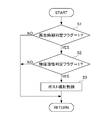
- the exhaust purification method includes a regeneration time determination step (step S1 in FIG. 2 and step S11 in FIG.
- the exhaust gas recirculation control and the second EGR control by the first EGR control means according to the exhaust system temperature detected by the exhaust system temperature detection means EGR switching step (steps S11 to S18 in FIG. 3) for switching between exhaust gas recirculation control by means.
- the first EGR passage that recirculates a part of the exhaust upstream of the turbine into the intake passage, and the first EGR control that controls the flow rate of the exhaust gas recirculated through the first EGR passage.
- a second EGR passage for recirculating a part of the exhaust downstream of the exhaust purification filter into the intake passage, and a second EGR control means for controlling the flow rate of the exhaust gas recirculated through the second EGR passage.
- the case where the exhaust gas recirculation control is performed by the first EGR control means is compared with the case where the exhaust gas recirculation control is performed by the second EGR control means.
- the exhaust gas recirculation control is performed by the first EGR control means
- the exhaust gas is taken out from the upstream side of the turbine. Therefore, the exhaust gas temperature can be quickly increased as compared with the case where the exhaust gas recirculation control is performed by the second EGR control means. Can do.
- the exhaust gas recirculation control is performed by the first EGR control means during the post injection for burning the particulate matter collected by the exhaust gas purification filter, the fuel supplied by the post injection is reduced. Since most of the fuel does not reach the oxidation catalyst and is recirculated, an extra fuel is required as compared with the case where the exhaust gas recirculation control is performed by the second EGR control means.
- the exhaust by the first EGR control means as described above.
- the exhaust gas recirculation control by the second EGR control means are switched according to the exhaust system temperature.
- the exhaust gas recirculation control is performed by the first EGR control means to quickly increase the exhaust temperature, or when the exhaust system temperature is high, the second EGR control means
- the particulate matter can be burned without consuming excess fuel.
- the exhaust purification filter can be regenerated with high efficiency without deteriorating fuel consumption.
- the NOx emission amount can also be reduced by continuing to perform the exhaust gas recirculation control by either the first EGR control means or the second EGR control means in this way.
- the exhaust gas recirculation control by the first EGR control means is selected. Therefore, since an oxidation catalyst can be activated quickly, consumption of excess fuel can be suppressed.
- the exhaust gas recirculation control by the second EGR control means when it is determined that the exhaust temperature has reached the combustion temperature of the particulate matter, the exhaust gas recirculation control by the second EGR control means is selected.
- the post-injection allows the unburned fuel supplied to the exhaust passage to efficiently reach the oxidation catalyst and be used for burning the particulate matter collected by the exhaust purification filter. Therefore, the fuel consumption required for regeneration of the exhaust purification filter can be suppressed.
- the unburned fuel can be burned by the oxidation catalyst, so that the unburned fuel adheres to the second EGR passage when the exhaust gas is recirculated. Can be suppressed.
- the post-injection amount is larger during the exhaust gas recirculation control by the second EGR control means than during the exhaust gas recirculation control by the first EGR control means. Reduced weight.
- the oxidation reaction in the oxidation catalyst can be realized with the same efficiency with less fuel than in the case where the exhaust gas recirculation control is performed by the first EGR control means. As a result, consumption of excess fuel can be suppressed.
- FIG. 1 is a diagram illustrating a configuration of an internal combustion engine and an exhaust purification device thereof according to an embodiment of the present invention. It is a flowchart which shows the procedure of the DPF regeneration process by ECU which concerns on the said embodiment. It is a flowchart which shows the procedure of the EGR switching process by ECU which concerns on the said embodiment. It is a figure which shows an EGR area
- FIG. 1 is a diagram showing a configuration of an internal combustion engine and an exhaust purification device thereof according to an embodiment of the present invention.
- An internal combustion engine (hereinafter referred to as “engine”) 1 is a diesel engine that directly injects fuel into the combustion chamber of each cylinder 7, and each cylinder 7 is provided with a fuel injection valve (not shown).
- These fuel injection valves are electrically connected by an electronic control unit (hereinafter referred to as “ECU”) 40, and the valve opening time and valve closing time of the fuel injection valve are controlled by the ECU 40.
- ECU electronice control unit
- the engine 1 includes an intake pipe 2 through which intake air flows, an exhaust pipe 4 through which exhaust flows, a high-pressure EGR passage 6 and a low-pressure EGR passage 10 that recirculate a part of the exhaust to the intake air, and pumps intake air to the intake pipe 2. And a supercharger 8 is provided.
- the intake pipe 2 is connected to the intake port of each cylinder 7 of the engine 1 through a plurality of branch portions of the intake manifold 3.
- the exhaust pipe 4 is connected to the exhaust port of each cylinder 7 of the engine 1 through a plurality of branch portions of the exhaust manifold 5.
- the supercharger 8 includes a turbine 81 provided in the exhaust pipe 4 and a compressor 82 provided in the intake pipe 2.
- the turbine 81 is driven by the kinetic energy of the exhaust flowing through the exhaust pipe 4.
- the compressor 82 is driven by the rotation of the turbine 81 to pressurize the intake air and pump it into the intake pipe 2.
- the turbine 81 includes a plurality of variable vanes (not shown), and is configured to change the rotational speed of the turbine by changing the opening of the variable vanes.
- the vane opening degree is electromagnetically controlled by the ECU 40.
- a throttle valve 9 for controlling the intake air amount of the engine 1 is provided on the upstream side of the supercharger 8 in the intake pipe 2.
- the throttle valve 9 is connected to the ECU 40 via an actuator, and the opening degree is electromagnetically controlled by the ECU 40.
- the intake air amount controlled by the throttle valve 9 is detected by the air flow meter 21.
- the high pressure EGR passage 6 connects the exhaust manifold 5 and the intake manifold 3, and returns a part of the exhaust upstream of the turbine 81 to the downstream of the compressor 82 in the intake pipe 2.
- the high pressure EGR passage 6 is provided with a high pressure EGR valve 11 for controlling the flow rate of the recirculated exhaust gas.
- the high pressure EGR valve 11 is connected to the ECU 40 via an actuator (not shown), and the valve opening degree is electromagnetically controlled by the ECU 40.
- the low pressure EGR passage 10 connects a downstream side of a DPF 32 described later in the exhaust pipe 4 and an upstream side of the compressor 82 in the intake pipe 2, and a part of the exhaust downstream of the DPF 32 is connected to the compressor 82 in the intake pipe 2. Reflux upstream.
- the low pressure EGR passage 10 is provided with a low pressure EGR valve 12 that controls the flow rate of the recirculated exhaust gas.
- the low pressure EGR valve 12 is connected to the ECU 40 via an actuator (not shown), and the valve opening degree is electromagnetically controlled by the ECU 40.
- an oxidation catalyst 31 and a DPF (Diesel Particulate Filter) 32 are provided in this order from the upstream side of the exhaust pipe 4 downstream of the turbine 81.
- the oxidation catalyst 31 raises the temperature of the exhaust gas with heat generated by the reaction with the exhaust gas.
- platinum (Pt) acting as a catalyst is supported on an alumina (Al 2 O 3 ) carrier, zeolite having excellent HC adsorption action, and steam reforming action of HC.
- a material constituted by adding rhodium (Rh) excellent in the above is used.
- the DPF 32 When the exhaust gas passes through the fine holes in the filter wall, the DPF 32 causes particulate matter (hereinafter referred to as “PM (Particulate Matter)”) in the exhaust gas to pass through the filter wall surface and the filter wall. Collect by depositing in the pores.
- PM particulate Matter
- a ceramic porous body such as silicon carbide (SiC) is used.
- the ECU 40 includes a crank angle position sensor (not shown) that detects the rotation angle of the crankshaft of the engine 1, an accelerator sensor (not shown) that detects the amount of depression of an accelerator pedal of a vehicle driven by the engine 1, and an engine 1, a cooling water temperature sensor (not shown) for detecting the cooling water temperature, an in-cylinder pressure sensor (not shown) for detecting the pressure in the combustion chamber of each cylinder 7 of the engine 1, and an intake air amount (per unit time) of the engine 1 An air flow meter 21 for detecting the amount of air newly sucked into the engine 1, and an exhaust temperature sensor 22 for detecting the temperature of the exhaust gas flowing between the oxidation catalyst 31 and the DPF 32 in the exhaust pipe 4. Detection signals from these sensors are supplied to the ECU 40.
- the rotational speed of the engine 1 is calculated by the ECU 40 based on the output of the crank angle position sensor.
- the generated torque of the engine 1, that is, the load of the engine 1 is calculated by the ECU 40 based on the fuel injection amount of the engine 1.
- the fuel injection amount is calculated by the ECU 40 based on the output of the accelerator sensor.
- the ECU 40 shapes an input signal waveform from various sensors, corrects a voltage level to a predetermined level, converts an analog signal value into a digital signal value, and a central processing unit (hereinafter, “ CPU ”).
- the ECU 40 is a memory circuit that stores various arithmetic programs executed by the CPU, arithmetic results, and the like, and a fuel injection for the throttle valve 9, the high pressure EGR valve 11, the low pressure EGR valve 12, the supercharger 8, and the engine 1.
- An output circuit that outputs a control signal to a valve or the like.
- the ECU 40 includes a module including a DPF regeneration control unit 41 and an EGR control unit 42.
- a module including a DPF regeneration control unit 41 and an EGR control unit 42 the function of each module will be described.
- the DPF regeneration control unit 41 performs a DPF regeneration process which will be described later with reference to FIG. 2 to burn PM accumulated on the DPF 32 and regenerate the DPF 32.
- the EGR control unit 42 is a high-pressure EGR control unit 43 that controls the flow rate of exhaust gas recirculated through the high-pressure EGR passage 6, and a low-pressure EGR control unit 44 that controls the flow rate of exhaust gas recirculated through the low-pressure EGR passage 10.
- the exhaust gas recirculation control of the engine 1 is performed.
- the high-pressure EGR control unit 43 controls the opening degree of the high-pressure EGR valve 11 and the flow rate of exhaust gas recirculated through the high-pressure EGR passage 6. Further, while the exhaust gas recirculation control is performed by the high pressure EGR control unit 43, the low pressure EGR valve 12 is basically closed.
- the low pressure EGR control unit 44 controls the flow rate of the exhaust gas recirculated through the low pressure EGR passage 10 by controlling the opening degree of the low pressure EGR valve 12. Further, while the exhaust gas recirculation control is performed by the low pressure EGR control unit 44, the high pressure EGR valve 11 is basically closed.
- the EGR control unit 42 includes an EGR switching unit 45 that performs an EGR switching process for selectively switching between the exhaust gas recirculation control by the high pressure EGR control unit 43 and the exhaust gas recirculation control by the low pressure EGR control unit 44. A detailed procedure of the EGR switching process will be described later with reference to FIG.
- FIG. 2 is a flowchart showing the procedure of the DPF regeneration process. This DPF regeneration process is repeatedly executed at a predetermined cycle by the DPF regeneration control unit of the ECU.
- step S1 it is determined whether or not the reproduction time determination flag is “1”. If this determination is YES, the process proceeds to step S2, and if NO, the DPF regeneration process is ended.
- This regeneration time determination flag is a flag indicating that it is time to burn PM collected in the DPF, that is, time to regenerate the DPF, and the amount of PM collected in the DPF exceeds a predetermined value. In this case, “0” is changed to “1”.
- the PM accumulation amount is estimated from, for example, the history of the engine speed and the fuel injection amount, the travel distance, and the like. In addition, the PM accumulation amount can be estimated from the differential pressure between the upstream side and the downstream side of the DPF. Further, the regeneration timing determination flag is returned from “1” to “0” when the combustion of PM collected in the DPF is completed by executing post injection control (see step S3) described later. .
- step S2 it is determined whether or not the catalyst activity determination flag is “1”. If this determination is YES, the process proceeds to step S3, and if NO, the DPF regeneration process is terminated.
- the catalyst activity determination flag is a flag indicating that the oxidation catalyst is activated, that is, the oxidation catalyst temperature is higher than the activation temperature.
- the catalyst activation determination flag is changed from “0” to “1” when the detected value of the exhaust temperature sensor exceeds the activation temperature of the oxidation catalyst, and “1” when the detected value of the exhaust temperature sensor falls below the activation temperature. To "0".
- step S3 post injection control is executed, and the DPF regeneration process is terminated. More specifically, in this step S3, fuel injection that does not contribute to torque, that is, post injection is performed, and unburned fuel is burned by the oxidation catalyst. Thereby, the temperature of the exhaust gas flowing into the DPF is raised, and the PM collected in the DPF is burned.
- the post injection amount a predetermined instruction value set in advance is used. The post injection amount instruction value is appropriately changed in steps S15 and S16 of FIG.
- FIG. 3 is a flowchart showing a procedure of EGR switching processing. This EGR switching process is repeatedly executed at a predetermined cycle by the EGR switching unit of the ECU described above.
- step S11 it is determined whether or not the reproduction time determination flag is “1”. If this determination is YES, the process proceeds to step S13. If this determination is NO, the process proceeds to step S12.
- step S12 it is determined whether or not the current operation state is the high pressure EGR region. More specifically, whether or not the operating state is the high pressure EGR region is determined based on a control map as shown in FIG. If this determination is YES, the process proceeds to step S17, and high pressure EGR control, that is, exhaust gas recirculation control via the high pressure EGR passage is selected. If this determination is NO, the process proceeds to step S18, and low pressure EGR control, that is, exhaust gas recirculation control via the low pressure EGR passage is selected.
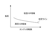
- FIG. 4 is a diagram illustrating an EGR region determination map, and is a diagram illustrating an example of a control map referred to in step S12 described above.
- the EGR region determination map is set based on a predetermined experiment and stored in the ECU.
- the engine speed and the load are used as parameters representing the operating state, and the operating state is divided into a low pressure EGR region suitable for low pressure EGR control and a high pressure EGR region suitable for high pressure EGR control.
- this control map basically, the high pressure EGR control is selected when the load is small, and the low pressure EGR control is selected when the load is large.
- the determination line that divides the high pressure EGR region and the low pressure EGR region becomes smaller as the engine speed increases. That is, when the engine speed increases, the low pressure EGR control is selected even with a small load.
- step S13 it is determined whether or not the catalyst activity determination flag is “1”. If this determination is YES, that is, if the oxidation catalyst is activated, the process proceeds to step S14. If this determination is NO, that is, if the temperature of the oxidation catalyst has not reached the activation temperature, the process proceeds to step S17, and high pressure EGR control is selected.
- step S14 it is determined whether or not the combustion determination flag is “1”. If this determination is YES, the process proceeds to step S16, and if NO, the process proceeds to step S15.
- the combustion determination flag is a flag indicating that the temperature of the exhaust gas flowing into the DPF is higher than the combustion temperature of PM. This combustion determination flag is changed from “0” to “1” when the detected value of the exhaust temperature sensor exceeds the PM combustion temperature, and “1” when the detected value of the exhaust temperature sensor falls below the PM combustion temperature. To "0". In general, the combustion temperature of PM is higher than the activation temperature of the oxidation catalyst.
- the catalyst activation determination flag is “1” and the combustion determination flag is “0”
- the oxidation catalyst is activated and the temperature of the exhaust gas flowing into the DPF is equal to or lower than the combustion temperature of PM. It can be said that there is a certain state, that is, the temperature of the exhaust gas does not reach the combustion temperature of PM, and the PM trapped in the DPF is not yet burned.
- the catalyst activity determination flag is “1” and the combustion determination flag is “1”
- the oxidation catalyst is activated and the temperature of the exhaust gas flowing into the DPF is higher than the combustion temperature of PM. It can be said that the state, that is, the temperature of the exhaust gas reaches the combustion temperature of PM and the PM trapped in the DPF is burning.
- step S15 the high pressure EGR control is selected after the post injection amount instruction value is changed to the high pressure EGR instruction value (step S17).
- step S16 the low pressure EGR control is selected after changing the instruction value of the post injection amount to the low pressure EGR instruction value smaller than the high pressure EGR instruction value described above (step S18).
- step S18 the post injection amount is reduced during the low pressure EGR control as compared with the high pressure EGR control.
- the high-pressure EGR control and the low-pressure EGR control are performed using the exhaust temperature sensor. Is switched according to the temperature of the exhaust gas detected by.
- the temperature of the exhaust gas is quickly increased by performing high pressure EGR control, or when the temperature of the exhaust gas is high, extra pressure can be obtained by performing low pressure EGR control.
- PM can be burned without consuming fuel.
- the DPF 32 can be regenerated with high efficiency without deteriorating fuel consumption.
- the NOx emission amount can also be reduced by continuing the exhaust gas recirculation control by either the high pressure EGR control or the low pressure EGR control.
- the high pressure EGR control is selected. Therefore, since the oxidation catalyst 31 can be activated quickly, consumption of excess fuel can be suppressed.
- the present embodiment when it is determined that it is time to burn PM, and when it is determined that the temperature of the oxidation catalyst 31 has reached the activation temperature, post injection is performed and the temperature of the exhaust gas is increased. To rise. Thereafter, when it is determined that the exhaust gas temperature has not reached the PM combustion temperature in the process of increasing the exhaust gas temperature, the high pressure EGR control is selected. As a result, the temperature of the exhaust gas can be quickly reached to the combustion temperature of PM, so that the fuel consumption required for regeneration of the DPF 32 can be suppressed.
- the low pressure EGR control when it is determined that the temperature of the exhaust gas has reached the combustion temperature of PM, the low pressure EGR control is selected.
- the unburned fuel supplied to the exhaust pipe 4 can efficiently reach the oxidation catalyst 31 by performing post injection, and can be used for combustion of the PM collected in the DPF 32. Therefore, the fuel consumption required for regeneration of the DPF 32 can be suppressed.
- the exhaust gas recirculation control by the low pressure EGR control the unburned fuel can be burned by the oxidation catalyst 31. Therefore, when the exhaust gas is recirculated, the unburned fuel adheres to the low pressure EGR passage 10. Can be suppressed.
- the post-injection amount is reduced during the low pressure EGR control as compared with the high pressure EGR control.
- the low pressure EGR control when the low pressure EGR control is performed, much of the fuel supplied by the post injection can reach the oxidation catalyst 31 as compared with the case where the high pressure EGR control is performed. Therefore, according to the present embodiment, the oxidation reaction in the oxidation catalyst 31 can be realized with the same efficiency with less fuel than in the case where the high pressure EGR control is performed. As a result, consumption of excess fuel can be suppressed.
- the ECU 40 constitutes a part of the first EGR control unit, a part of the second EGR control unit, a regeneration timing determination unit, an EGR switching unit, a catalyst activity determination unit, a regeneration execution unit, and a combustion determination unit.
- the high pressure EGR control unit 43 and the high pressure EGR valve 11 of the ECU 40 correspond to first EGR control means
- the low pressure EGR control unit 44 and the low pressure EGR valve 12 of the ECU 40 correspond to second EGR control means
- the EGR of the ECU 40 The switching unit 45 corresponds to EGR switching means
- the DPF regeneration control unit 41 of the ECU 40 corresponds to regeneration executing means.
- 2 corresponds to the regeneration timing determination means
- the means related to execution of step S2 in FIG. 2 and step S13 in FIG. 3 corresponds to the catalyst activity determination means.
- step S14 of FIG. 3 is equivalent to a combustion determination means.
- the exhaust temperature sensor 22 for detecting the temperature of the exhaust gas between the oxidation catalyst 31 and the DPF 32 is used as the exhaust system temperature detecting means for detecting the temperature of the exhaust system of the engine 1.
- the present invention is not limited to this.
- the temperature of the exhaust system includes not only the temperature of the exhaust gas between the oxidation catalyst and the DPF, but also the temperature of the oxidation catalyst or the DPF itself. Therefore, an exhaust system temperature detecting means that directly detects the temperature of the oxidation catalyst or DPF may be used.
- the oxidation catalyst 31 and the DPF 32 are provided separately, but the present invention is not limited to this.
- Engine internal combustion engine 2 ... Intake pipe (intake passage) 3. Intake manifold (intake passage) 4 ... Exhaust pipe 5 ... Exhaust manifold 6 ... High pressure EGR passage (first EGR passage) 11 ... High pressure EGR valve (first EGR control means) 10 ... Low pressure EGR passage (second EGR passage) 12 ... Low pressure EGR valve (second EGR control means) 8 ... supercharger 22 ... exhaust temperature sensor (exhaust system temperature detecting means) 31 ... Oxidation catalyst 32 ... DPF (Exhaust gas purification filter) 40.
- ECU first EGR control means, second EGR control means, regeneration timing determination means, EGR switching means, catalyst activity determination means, regeneration execution means, combustion determination means)
Abstract
Disclosed is an internal combustion engine exhaust purifying device that can regenerate the exhaust purifying filter with high efficiency without reducing mileage.
The exhaust purifying device of an engine (1) is provided with a supercharger (8), a DPF (32), an oxidation catalyst (31), a high pressure EGR path (6) that recirculates a portion of the upstream exhaust from a turbine (81) into an intake tube (2), a high pressure EGR valve (11) and a high pressure EGR control unit (43) that control the flow of the exhaust that is recirculated via the high pressure EGR path (6), a low pressure EGR path (10) that recirculates a portion of the downstream exhaust from the DPF (32) into the intake tube (2), a low pressure EGR valve (12) and a low pressure EGR control unit (44) that control the flow of the exhaust that is recirculated via the low pressure EGR path (10), an exhaust temperature sensor (22) that detects the temperature of the exhaust, and an EGR switching unit (45) that switches between exhaust recirculation control by the high pressure EGR control unit (43) and exhaust recirculation control by the low pressure EGR control unit (44) according to values detected by the exhaust temperature sensor when it is determined to be a period when the PM collected in the DPF will be burned.
Description
本発明は、内燃機関の排気浄化装置及び排気浄化方法に関する。詳しくは、内燃機関から排出される排気中に含まれる粒子状物質を捕集する排気浄化フィルタを備える排気浄化装置及び排気浄化方法に関する。
The present invention relates to an exhaust purification device and an exhaust purification method for an internal combustion engine. More specifically, the present invention relates to an exhaust gas purification apparatus and an exhaust gas purification method including an exhaust gas purification filter that collects particulate matter contained in exhaust gas discharged from an internal combustion engine.
ディーゼルエンジンやリーンバーンエンジンなどでは、シリンダ内における空燃比が不均質となり、局所的にリッチとなった部分において酸素が不足した状態で燃焼することにより、炭素を主成分とした粒子状物質が排出される。そこで、このような粒子状物質の排出量を低減するため、排気系に、排気中の粒子状物質を捕集する排気浄化フィルタを設ける技術が広く用いられている。この排気浄化フィルタが捕集できる粒子状物質の量には限界があるため、排気浄化フィルタに堆積した粒子状物質を燃焼させるフィルタ再生処理が適宜実行される。
In diesel engines, lean burn engines, etc., the air-fuel ratio in the cylinder becomes inhomogeneous, and combustion occurs with oxygen deficient in areas that are locally rich, thereby discharging particulate matter composed mainly of carbon. Is done. Therefore, in order to reduce the discharge amount of such particulate matter, a technique in which an exhaust gas purification filter that collects particulate matter in the exhaust gas is provided in the exhaust system is widely used. Since there is a limit to the amount of particulate matter that can be collected by the exhaust purification filter, filter regeneration processing for combusting particulate matter deposited on the exhaust purification filter is appropriately performed.
このフィルタ再生処理では、具体的には、ポスト噴射を実行し、排気中の未燃燃料を増加させる。これにより、排気浄化フィルタに担持された酸化触媒、又は、排気浄化フィルタの上流に設けられた酸化触媒での酸化反応を促進し、排気浄化フィルタに流入する排気の温度を粒子状物質の燃焼温度まで上昇させ、堆積した粒子状物質を燃焼する。
In this filter regeneration process, specifically, post injection is executed to increase the unburned fuel in the exhaust. As a result, the oxidation reaction carried out by the oxidation catalyst carried on the exhaust purification filter or the oxidation catalyst provided upstream of the exhaust purification filter is promoted, and the temperature of the exhaust flowing into the exhaust purification filter is changed to the combustion temperature of the particulate matter. And the deposited particulate matter is burned.
一方、内燃機関の排気の一部を吸気に還流し、新気と排気を混合させることによりシリンダでの燃焼温度を低下させ、内燃機関から排出されるNOxを低減する技術(以下、EGR技術という)が知られている。
On the other hand, a technology for reducing NOx discharged from the internal combustion engine (hereinafter referred to as EGR technology) by lowering the combustion temperature in the cylinder by mixing a part of the exhaust gas of the internal combustion engine into the intake air and mixing fresh air and exhaust gas. )It has been known.
例えば特許文献1には、上述のようなEGR技術をフィルタ再生処理に適用した内燃機関の排気浄化装置が提案されている。この排気浄化装置では、排気系のうち過給機のタービンの下流側に設けられた排気浄化フィルタに対し、フィルタ再生処理を行っている間は、内燃機関の負荷の大きさに応じて排気の還流先を変更する。
For example, Patent Document 1 proposes an exhaust gas purification apparatus for an internal combustion engine in which the above-described EGR technique is applied to filter regeneration processing. In this exhaust purification device, during the filter regeneration process for the exhaust purification filter provided on the downstream side of the turbine of the turbocharger in the exhaust system, the exhaust purification device is operated according to the load of the internal combustion engine. Change the reflux destination.
より具体的には、フィルタ再生処理を行っている間において、内燃機関が高負荷である場合には、排気浄化フィルタの下流側から取り出した排気を過給機のインタークーラの上流側に還流し、内燃機関が低負荷である場合には、排気浄化フィルタの下流側から取り出した排気をインタークーラの下流側に還流する。このように、内燃機関の低負荷時には、インタークーラをバイパスするようにしてインタークーラの下流側に還流することにより、燃焼温度が過剰に低下して燃焼が不安定になるのを防止している。
More specifically, when the internal combustion engine has a high load during the filter regeneration process, the exhaust gas extracted from the downstream side of the exhaust purification filter is returned to the upstream side of the intercooler of the supercharger. When the internal combustion engine has a low load, the exhaust gas taken out from the downstream side of the exhaust purification filter is returned to the downstream side of the intercooler. Thus, when the internal combustion engine is under a low load, the intercooler is bypassed to return to the downstream side of the intercooler, thereby preventing the combustion temperature from being excessively lowered and the combustion becoming unstable. .
ところで、特許文献1に記載された排気浄化装置では、フィルタ再生処理を行っている間は、常に排気浄化フィルタの下流側から排気が取り出される。排気浄化フィルタの下流側の排気は、タービン及び排気浄化フィルタを通過したものであるため、例えばタービンの上流側の排気よりも冷たい。したがって、このような排気浄化フィルタの下流側の排気を、フィルタ再生処理を行っている間、常に還流し続けると、その燃焼による排気の温度も低くなってしまい、排気の温度が粒子状物質の燃焼温度に達するまでに時間がかかってしまう。結果として、フィルタの再生に余分な時間がかかり、この余分な時間の分だけ燃費が悪化するおそれがある。
By the way, in the exhaust gas purification device described in Patent Document 1, exhaust gas is always taken out from the downstream side of the exhaust gas purification filter during the filter regeneration process. Since the exhaust on the downstream side of the exhaust purification filter has passed through the turbine and the exhaust purification filter, it is cooler than the exhaust on the upstream side of the turbine, for example. Therefore, if the exhaust gas downstream of the exhaust gas purification filter is continuously recirculated during the filter regeneration process, the temperature of the exhaust gas due to the combustion also becomes lower, and the temperature of the exhaust gas becomes the particulate matter. It takes time to reach the combustion temperature. As a result, it takes an extra time to regenerate the filter, and there is a risk that the fuel consumption will deteriorate by this extra time.
本発明は上述した点を考慮してなされたものであり、燃費を悪化することなく高効率で排気浄化フィルタを再生できる内燃機関の排気浄化装置を提供することを目的とする。
The present invention has been made in consideration of the above-described points, and an object thereof is to provide an exhaust purification device for an internal combustion engine that can regenerate an exhaust purification filter with high efficiency without deteriorating fuel consumption.
上記目的を達成するため請求項1に記載の発明は、内燃機関(1)の排気系に設けられたタービン(81)の回転によりコンプレッサ(82)を駆動する過給機(8)と、前記排気系のうち前記タービンよりも下流側に設けられ、排気中の粒子状物質を捕集する排気浄化フィルタ(32)と、を備える内燃機関の排気浄化装置を提供する。前記排気浄化装置は、前記タービンの上流の排気の一部を前記内燃機関の吸気通路(2,3)内に還流する第1EGR通路(6)と、当該第1EGR通路を介して還流される排気の流量を制御する第1EGR制御手段(11,40,43)と、前記排気浄化フィルタの下流の排気の一部を前記吸気通路内に還流する第2EGR通路(10)と、当該第2EGR通路を介して還流される排気の流量を制御する第2EGR制御手段(12,40,44)と、前記排気系の温度を検出する排気系温度検出手段(22)と、前記排気浄化フィルタに捕集された粒子状物質を燃焼させる時期であるか否かを判定する再生時期判定手段(40)と、前記粒子状物質を燃焼させる時期であると判定された場合には、前記排気系温度検出手段により検出された排気系温度に応じて前記第1EGR制御手段による排気の還流制御と前記第2EGR制御手段による排気の還流制御とを切り替えるEGR切替手段(40,45)と、を備える。
In order to achieve the above object, the invention described in claim 1 includes a supercharger (8) for driving a compressor (82) by rotation of a turbine (81) provided in an exhaust system of the internal combustion engine (1), Provided is an exhaust gas purification apparatus for an internal combustion engine, comprising an exhaust gas purification filter (32) provided downstream of the turbine in an exhaust system and collecting particulate matter in the exhaust gas. The exhaust emission control device includes a first EGR passage (6) that recirculates part of the exhaust upstream of the turbine into the intake passage (2, 3) of the internal combustion engine, and an exhaust gas that is recirculated through the first EGR passage. First EGR control means (11, 40, 43) for controlling the flow rate of the exhaust gas, a second EGR passage (10) for returning a part of the exhaust gas downstream of the exhaust purification filter into the intake passage, and the second EGR passage. The second EGR control means (12, 40, 44) for controlling the flow rate of the exhaust gas recirculated through the exhaust system, the exhaust system temperature detection means (22) for detecting the temperature of the exhaust system, and the exhaust purification filter. Regeneration time determining means (40) for determining whether it is time to burn the particulate matter, and if it is determined that it is time to burn the particulate matter, the exhaust system temperature detecting means was detected It includes an EGR switching means in accordance with the exhaust system temperature switch between recirculation control of the exhaust gas by the first 2EGR control means and recirculation control of the exhaust gas by the first 1EGR control means (40, 45), the.
請求項2に記載の発明は、請求項1に記載の内燃機関の排気浄化装置において、前記排気系のうち前記排気浄化フィルタよりも上流側に設けられた酸化触媒(31)と、前記排気系温度検出手段により検出された排気系温度に基づいて、前記酸化触媒の温度がその活性温度に達したか否かを判定する触媒活性判定手段(40)をさらに備える。前記EGR切替手段は、前記酸化触媒の温度が前記活性温度に達していないと判定された場合には、前記第1EGR制御手段による排気の還流制御を選択する。
According to a second aspect of the present invention, in the exhaust gas purification apparatus for an internal combustion engine according to the first aspect, an oxidation catalyst (31) provided upstream of the exhaust gas purification filter in the exhaust system, and the exhaust system Based on the exhaust system temperature detected by the temperature detection means, further comprises catalyst activity determination means (40) for determining whether or not the temperature of the oxidation catalyst has reached its activation temperature. The EGR switching means selects exhaust gas recirculation control by the first EGR control means when it is determined that the temperature of the oxidation catalyst has not reached the activation temperature.
請求項3に記載の発明は、請求項2に記載の内燃機関の排気浄化装置において、前記粒子状物質を燃焼させる時期であると判定され、かつ、前記酸化触媒の温度が前記活性温度に達したと判定された場合には、ポスト噴射を行うことで前記排気浄化フィルタに流入する排気の温度を上昇させる再生実行手段(40,41)と、前記排気系温度検出手段により検出された排気系温度に基づいて、前記排気浄化フィルタに流入する排気の温度が粒子状物質の燃焼温度に達したか否かを判定する燃焼判定手段と、をさらに備える。前記EGR切替手段は、前記排気の温度が前記燃焼温度に達していないと判定された場合には、前記第1EGR制御手段による排気の還流制御を選択する。
According to a third aspect of the present invention, in the exhaust gas purification apparatus for an internal combustion engine according to the second aspect, it is determined that it is time to burn the particulate matter, and the temperature of the oxidation catalyst reaches the activation temperature. If it is determined that the exhaust gas is exhausted, the regeneration executing means (40, 41) for raising the temperature of the exhaust gas flowing into the exhaust gas purification filter by performing post injection, and the exhaust system detected by the exhaust system temperature detecting means. Combustion determining means for determining whether the temperature of the exhaust gas flowing into the exhaust gas purification filter has reached the combustion temperature of the particulate matter based on the temperature. The EGR switching means selects exhaust gas recirculation control by the first EGR control means when it is determined that the temperature of the exhaust gas has not reached the combustion temperature.
請求項4に記載の発明は、請求項3に記載の内燃機関の排気浄化装置において、前記EGR切替手段は、前記排気の温度が前記燃焼温度に達したと判定された場合には、前記第2EGR制御手段による排気の還流制御を選択する。
According to a fourth aspect of the present invention, in the exhaust gas purification apparatus for an internal combustion engine according to the third aspect, when the EGR switching means determines that the temperature of the exhaust gas has reached the combustion temperature, the first 2. Select the exhaust gas recirculation control by the EGR control means.
請求項5に記載の発明は、請求項3又は4に記載の内燃機関の排気浄化装置において、前記第2EGR制御手段により排気の還流制御が行われている間は、前記第1EGR制御手段により排気の還流制御が行われている間よりも、ポスト噴射量が減量される。
According to a fifth aspect of the present invention, in the exhaust gas purification apparatus for an internal combustion engine according to the third or fourth aspect, the exhaust gas is recirculated by the first EGR control means while the exhaust gas recirculation control is being performed by the second EGR control means. The post-injection amount is reduced as compared to when the recirculation control is being performed.
請求項6記載の発明は、内燃機関(1)の排気系に設けられたタービン(81)の回転によりコンプレッサ(82)を駆動する過給機(8)と、前記排気系のうち前記タービンよりも下流側に設けられ、排気中の粒子状物質を捕集する排気浄化フィルタ(32)と、前記タービンの上流の排気の一部を前記内燃機関の吸気通路(2,3)内に還流する第1EGR通路(6)と、当該第1EGR通路を介して還流される排気の流量を制御する第1EGR制御手段(11,40,43)と、前記排気浄化フィルタの下流の排気の一部を前記吸気通路内に還流する第2EGR通路(10)と、当該第2EGR通路を介して還流される排気の流量を制御する第2EGR制御手段(12,40,44)と、前記排気系の温度を検出する排気系温度検出手段(22)と、を備える内燃機関の排気浄化方法を提供する。前記排気浄化方法は、前記排気浄化フィルタに捕集された粒子状物質を燃焼させる時期であるか否かを判定する再生時期判定工程(図2のステップS1及び図3のステップS11の工程)と、前記粒子状物質を燃焼させる時期であると判定された場合には、前記排気系温度検出手段により検出された排気系温度に応じて前記第1EGR制御手段による排気の還流制御と前記第2EGR制御手段による排気の還流制御とを切り替えるEGR切替工程(図3のステップS11~18の工程)と、を含む。
The invention described in claim 6 includes a supercharger (8) for driving a compressor (82) by rotation of a turbine (81) provided in an exhaust system of the internal combustion engine (1), and the turbine of the exhaust system. And an exhaust purification filter (32) for collecting particulate matter in the exhaust, and a part of the exhaust upstream of the turbine is returned to the intake passage (2, 3) of the internal combustion engine. A first EGR passage (6), first EGR control means (11, 40, 43) for controlling the flow rate of exhaust gas recirculated through the first EGR passage, and a part of the exhaust gas downstream of the exhaust gas purification filter A second EGR passage (10) that recirculates into the intake passage, a second EGR control means (12, 40, 44) that controls the flow rate of the exhaust gas recirculated through the second EGR passage, and the temperature of the exhaust system are detected Exhaust system temperature detection A stage (22), to provide an exhaust purification method for an internal combustion engine provided with a. The exhaust purification method includes a regeneration time determination step (step S1 in FIG. 2 and step S11 in FIG. 3) for determining whether it is time to burn the particulate matter collected by the exhaust purification filter. When it is determined that it is time to burn the particulate matter, the exhaust gas recirculation control and the second EGR control by the first EGR control means according to the exhaust system temperature detected by the exhaust system temperature detection means EGR switching step (steps S11 to S18 in FIG. 3) for switching between exhaust gas recirculation control by means.
請求項1に記載の発明によれば、タービンの上流の排気の一部を吸気通路内に還流する第1EGR通路と、この第1EGR通路を介して還流される排気の流量を制御する第1EGR制御手段と、排気浄化フィルタの下流の排気の一部を吸気通路内に還流する第2EGR通路と、この第2EGR通路を介して還流される排気の流量を制御する第2EGR制御手段と、を設けた。
According to the first aspect of the present invention, the first EGR passage that recirculates a part of the exhaust upstream of the turbine into the intake passage, and the first EGR control that controls the flow rate of the exhaust gas recirculated through the first EGR passage. And a second EGR passage for recirculating a part of the exhaust downstream of the exhaust purification filter into the intake passage, and a second EGR control means for controlling the flow rate of the exhaust gas recirculated through the second EGR passage. .
ここで、第1EGR制御手段により排気の還流制御を行った場合と、第2EGR制御手段により排気の還流制御を行った場合とを比較する。
第1EGR制御手段により排気の還流制御を行った場合、排気はタービンの上流から取り出されるため、第2EGR制御手段により排気の還流制御を行った場合と比較すると、排気の温度を速やかに上昇させることができる。
これに対し、排気浄化フィルタに捕集された粒子状物質を燃焼させるためにポスト噴射を行っている間では、第1EGR制御手段により排気の還流制御を行った場合、ポスト噴射で供給した燃料の多くが酸化触媒まで到達せず還流されてしまうため、第2EGR制御手段により排気の還流制御を行った場合と比較すると、余分な燃料が必要となる。 Here, the case where the exhaust gas recirculation control is performed by the first EGR control means is compared with the case where the exhaust gas recirculation control is performed by the second EGR control means.
When the exhaust gas recirculation control is performed by the first EGR control means, the exhaust gas is taken out from the upstream side of the turbine. Therefore, the exhaust gas temperature can be quickly increased as compared with the case where the exhaust gas recirculation control is performed by the second EGR control means. Can do.
On the other hand, when the exhaust gas recirculation control is performed by the first EGR control means during the post injection for burning the particulate matter collected by the exhaust gas purification filter, the fuel supplied by the post injection is reduced. Since most of the fuel does not reach the oxidation catalyst and is recirculated, an extra fuel is required as compared with the case where the exhaust gas recirculation control is performed by the second EGR control means.
請求項1に記載の発明によれば、排気浄化フィルタに粒子状物質が堆積し、この粒子状物質を燃焼させる時期であると判定された場合には、上述のような第1EGR制御手段による排気の還流制御と第2EGR制御手段による排気の還流制御とを、排気系温度に応じて切り替える。
これにより、例えば、排気系温度が低い場合には、第1EGR制御手段により排気の還流制御を行うことで速やかに排気の温度を上昇させたり、排気系温度が高い場合には、第2EGR制御手段により排気の還流制御を行うことで、余分な燃料を消費することなく粒子状物質を燃焼させたりすることができる。結果として、燃費を悪化することなく高効率で排気浄化フィルタを再生することができる。また、このようにして、第1EGR制御手段及び第2EGR制御手段の何れかで排気の還流制御を行い続けることにより、NOx排出量も低減することができる。 According to the first aspect of the present invention, when it is determined that it is time to deposit particulate matter on the exhaust gas purification filter and burn this particulate matter, the exhaust by the first EGR control means as described above. And the exhaust gas recirculation control by the second EGR control means are switched according to the exhaust system temperature.
Thus, for example, when the exhaust system temperature is low, the exhaust gas recirculation control is performed by the first EGR control means to quickly increase the exhaust temperature, or when the exhaust system temperature is high, the second EGR control means By performing the exhaust gas recirculation control, the particulate matter can be burned without consuming excess fuel. As a result, the exhaust purification filter can be regenerated with high efficiency without deteriorating fuel consumption. Further, the NOx emission amount can also be reduced by continuing to perform the exhaust gas recirculation control by either the first EGR control means or the second EGR control means in this way.
請求項2に記載の発明によれば、酸化触媒が活性温度に達していないと判定された場合には、第1EGR制御手段による排気の還流制御が選択される。これにより、酸化触媒を速やかに活性化させることができるので、余分な燃料の消費を抑制することができる。
According to the second aspect of the present invention, when it is determined that the oxidation catalyst has not reached the activation temperature, the exhaust gas recirculation control by the first EGR control means is selected. Thereby, since an oxidation catalyst can be activated quickly, consumption of excess fuel can be suppressed.
請求項3に記載の発明によれば、粒子状物質を燃焼させる時期であると判定され、かつ、酸化触媒の温度が活性温度に達したと判定された場合には、ポスト噴射が行われ、排気の温度が上昇する。その後、排気の温度が上昇する過程において、排気の温度が粒子状物質の燃焼温度に達していないと判定された場合には、第1EGR制御手段による排気の還流制御が選択される。これにより、排気の温度を、粒子状物質の燃焼温度に速やかに到達させることができるので、排気浄化フィルタの再生にかかる燃費を抑制することができる。
According to the invention described in claim 3, when it is determined that it is time to burn the particulate matter, and when it is determined that the temperature of the oxidation catalyst has reached the activation temperature, post injection is performed, The exhaust temperature rises. Thereafter, when it is determined that the exhaust temperature has not reached the combustion temperature of the particulate matter in the process of increasing the exhaust temperature, the exhaust gas recirculation control by the first EGR control means is selected. As a result, the temperature of the exhaust gas can be quickly reached the combustion temperature of the particulate matter, so that the fuel consumption required for regeneration of the exhaust gas purification filter can be suppressed.
請求項4に記載の発明によれば、排気の温度が粒子状物質の燃焼温度に達したと判定された場合には、第2EGR制御手段による排気の還流制御が選択される。これにより、ポスト噴射を実行することで排気通路に供給した未燃燃料を効率よく酸化触媒に到達させて、排気浄化フィルタに捕集された粒子状物質の燃焼に供することができる。したがって、排気浄化フィルタの再生にかかる燃費を抑制することができる。また、第2EGR制御手段による排気の還流制御を選択することにより、未燃燃料を酸化触媒で燃焼させることができるので、排気を還流する際に、第2EGR通路に未燃燃料が付着するのを抑制することができる。
According to the fourth aspect of the invention, when it is determined that the exhaust temperature has reached the combustion temperature of the particulate matter, the exhaust gas recirculation control by the second EGR control means is selected. As a result, the post-injection allows the unburned fuel supplied to the exhaust passage to efficiently reach the oxidation catalyst and be used for burning the particulate matter collected by the exhaust purification filter. Therefore, the fuel consumption required for regeneration of the exhaust purification filter can be suppressed. Further, by selecting the exhaust gas recirculation control by the second EGR control means, the unburned fuel can be burned by the oxidation catalyst, so that the unburned fuel adheres to the second EGR passage when the exhaust gas is recirculated. Can be suppressed.
請求項5に記載の発明によれば、第2EGR制御手段により排気の還流制御が行われている間は、第1EGR制御手段により排気の還流制御が行われている間よりも、ポスト噴射量が減量される。
上述のように、第2EGR制御手段により排気の還流制御を行った場合、第1EGR制御手段により排気の還流制御を行った場合と比較すると、ポスト噴射で供給した燃料の多くを酸化触媒まで到達させることができる。したがって、請求項5に記載の発明によれば、第1EGR制御手段により排気の還流制御を行っている場合よりも少ない燃料で、同等の効率で酸化触媒における酸化反応を実現することができる。結果として、余分な燃料の消費を抑制することができる。 According to the fifth aspect of the present invention, the post-injection amount is larger during the exhaust gas recirculation control by the second EGR control means than during the exhaust gas recirculation control by the first EGR control means. Reduced weight.
As described above, when the exhaust gas recirculation control is performed by the second EGR control means, much of the fuel supplied by the post injection reaches the oxidation catalyst as compared with the case where the exhaust gas recirculation control is performed by the first EGR control means. be able to. Therefore, according to the fifth aspect of the present invention, the oxidation reaction in the oxidation catalyst can be realized with the same efficiency with less fuel than in the case where the exhaust gas recirculation control is performed by the first EGR control means. As a result, consumption of excess fuel can be suppressed.
請求項6に記載の発明によれば、請求項1に記載の発明と同様の効果が奏される。
According to the invention described in claim 6, the same effect as the invention described in claim 1 can be obtained.
以下、本発明の実施形態について図面を参照しながら詳細に説明する。
Hereinafter, embodiments of the present invention will be described in detail with reference to the drawings.
図1は、本発明の一実施形態に係る内燃機関及びその排気浄化装置の構成を示す図である。内燃機関(以下、「エンジン」という)1は、各気筒7の燃焼室内に燃料を直接噴射するディーゼルエンジンであり、各気筒7には図示しない燃料噴射弁が設けられている。これら燃料噴射弁は、電子制御ユニット(以下、「ECU」という)40により電気的に接続されており、燃料噴射弁の開弁時間及び閉弁時間は、ECU40により制御される。
FIG. 1 is a diagram showing a configuration of an internal combustion engine and an exhaust purification device thereof according to an embodiment of the present invention. An internal combustion engine (hereinafter referred to as “engine”) 1 is a diesel engine that directly injects fuel into the combustion chamber of each cylinder 7, and each cylinder 7 is provided with a fuel injection valve (not shown). These fuel injection valves are electrically connected by an electronic control unit (hereinafter referred to as “ECU”) 40, and the valve opening time and valve closing time of the fuel injection valve are controlled by the ECU 40.
エンジン1には、吸気が流通する吸気管2と、排気が流通する排気管4と、排気の一部を吸気に還流する高圧EGR通路6及び低圧EGR通路10と、吸気管2に吸気を圧送する過給機8と、が設けられている。
The engine 1 includes an intake pipe 2 through which intake air flows, an exhaust pipe 4 through which exhaust flows, a high-pressure EGR passage 6 and a low-pressure EGR passage 10 that recirculate a part of the exhaust to the intake air, and pumps intake air to the intake pipe 2. And a supercharger 8 is provided.
吸気管2は、吸気マニホールド3の複数の分岐部を介してエンジン1の各気筒7の吸気ポートに接続されている。排気管4は、排気マニホールド5の複数の分岐部を介してエンジン1の各気筒7の排気ポートに接続されている。
The intake pipe 2 is connected to the intake port of each cylinder 7 of the engine 1 through a plurality of branch portions of the intake manifold 3. The exhaust pipe 4 is connected to the exhaust port of each cylinder 7 of the engine 1 through a plurality of branch portions of the exhaust manifold 5.
過給機8は、排気管4に設けられたタービン81と、吸気管2に設けられたコンプレッサ82と、を備える。タービン81は、排気管4を流通する排気の運動エネルギにより駆動される。コンプレッサ82は、タービン81の回転により駆動され、吸気を加圧し吸気管2内へ圧送する。また、タービン81は、図示しない複数の可変ベーンを備えており、可変ベーンの開度を変化させることにより、タービンの回転速度を変更できるように構成されている。ベーン開度は、ECU40により電磁的に制御される。
The supercharger 8 includes a turbine 81 provided in the exhaust pipe 4 and a compressor 82 provided in the intake pipe 2. The turbine 81 is driven by the kinetic energy of the exhaust flowing through the exhaust pipe 4. The compressor 82 is driven by the rotation of the turbine 81 to pressurize the intake air and pump it into the intake pipe 2. The turbine 81 includes a plurality of variable vanes (not shown), and is configured to change the rotational speed of the turbine by changing the opening of the variable vanes. The vane opening degree is electromagnetically controlled by the ECU 40.
吸気管2のうち過給機8の上流側には、エンジン1の吸入空気量を制御するスロットル弁9が設けられている。このスロットル弁9は、アクチュエータを介してECU40に接続されており、その開度はECU40により電磁的に制御される。スロットル弁9により制御された吸入空気量は、エアフローメータ21により検出される。
A throttle valve 9 for controlling the intake air amount of the engine 1 is provided on the upstream side of the supercharger 8 in the intake pipe 2. The throttle valve 9 is connected to the ECU 40 via an actuator, and the opening degree is electromagnetically controlled by the ECU 40. The intake air amount controlled by the throttle valve 9 is detected by the air flow meter 21.
高圧EGR通路6は、排気マニホールド5と吸気マニホールド3とを接続し、タービン81の上流の排気の一部を、吸気管2のうちコンプレッサ82の下流に還流する。高圧EGR通路6には、還流する排気の流量を制御する高圧EGR弁11が設けられている。高圧EGR弁11は、図示しないアクチュエータを介してECU40に接続されており、その弁開度はECU40により電磁的に制御される。
The high pressure EGR passage 6 connects the exhaust manifold 5 and the intake manifold 3, and returns a part of the exhaust upstream of the turbine 81 to the downstream of the compressor 82 in the intake pipe 2. The high pressure EGR passage 6 is provided with a high pressure EGR valve 11 for controlling the flow rate of the recirculated exhaust gas. The high pressure EGR valve 11 is connected to the ECU 40 via an actuator (not shown), and the valve opening degree is electromagnetically controlled by the ECU 40.
低圧EGR通路10は、排気管4のうち後述のDPF32の下流側と吸気管2のうちコンプレッサ82の上流側とを接続し、DPF32の下流の排気の一部を、吸気管2のうちコンプレッサ82の上流に還流する。低圧EGR通路10には、還流する排気の流量を制御する低圧EGR弁12が設けられている。低圧EGR弁12は、図示しないアクチュエータを介してECU40に接続されており、その弁開度はECU40により電磁的に制御される。
The low pressure EGR passage 10 connects a downstream side of a DPF 32 described later in the exhaust pipe 4 and an upstream side of the compressor 82 in the intake pipe 2, and a part of the exhaust downstream of the DPF 32 is connected to the compressor 82 in the intake pipe 2. Reflux upstream. The low pressure EGR passage 10 is provided with a low pressure EGR valve 12 that controls the flow rate of the recirculated exhaust gas. The low pressure EGR valve 12 is connected to the ECU 40 via an actuator (not shown), and the valve opening degree is electromagnetically controlled by the ECU 40.
この他、排気管4のうちタービン81の下流には、酸化触媒31とDPF(Diesel Particulate Filter)32と、が上流側からこの順で設けられている。
In addition, an oxidation catalyst 31 and a DPF (Diesel Particulate Filter) 32 are provided in this order from the upstream side of the exhaust pipe 4 downstream of the turbine 81.
酸化触媒31は、排気との反応により発生する熱で排気を昇温する。この酸化触媒31には、例えば、触媒として作用する白金(Pt)を、アルミナ(Al2O3)担体に担持させたものに、HCの吸着作用に優れたゼオライトと、HCの水蒸気改質作用に優れたロジウム(Rh)を加えて構成されたものが用いられる。
The oxidation catalyst 31 raises the temperature of the exhaust gas with heat generated by the reaction with the exhaust gas. In this oxidation catalyst 31, for example, platinum (Pt) acting as a catalyst is supported on an alumina (Al 2 O 3 ) carrier, zeolite having excellent HC adsorption action, and steam reforming action of HC. In addition, a material constituted by adding rhodium (Rh) excellent in the above is used.
DPF32は、排気がフィルタ壁の微細な孔を通過する際、排気中の炭素を主成分とする粒子状物質(以下、「PM(Particulate Matter)」という)を、フィルタ壁の表面及びフィルタ壁中の孔に堆積させることによって捕集する。フィルタ壁の構成材料としては、例えば、炭化珪素(SiC)などのセラミックスの多孔体が使用される。DPF32の捕集能力の限界、すなわち堆積限界までPMを捕集すると、排気管4の圧損が大きくなるので、捕集したPMを燃焼させる後述のDPF再生処理が行われる。
When the exhaust gas passes through the fine holes in the filter wall, the DPF 32 causes particulate matter (hereinafter referred to as “PM (Particulate Matter)”) in the exhaust gas to pass through the filter wall surface and the filter wall. Collect by depositing in the pores. As a constituent material of the filter wall, for example, a ceramic porous body such as silicon carbide (SiC) is used. When PM is collected up to the limit of the collection capability of the DPF 32, that is, the accumulation limit, the pressure loss of the exhaust pipe 4 increases, so that a DPF regeneration process described later for burning the collected PM is performed.
ECU40には、エンジン1のクランク軸の回転角度を検出するクランク角度位置センサ(図示せず)、エンジン1により駆動される車両のアクセルペダルの踏み込み量を検出するアクセルセンサ(図示せず)、エンジン1の冷却水温を検出する冷却水温センサ(図示せず)、エンジン1の各気筒7の燃焼室内における圧力を検出する筒内圧センサ(図示せず)、エンジン1の吸入空気量(単位時間当りにエンジン1に新規に吸入される空気量)を検出するエアフローメータ21、排気管4のうち酸化触媒31とDPF32との間を流通する排気の温度を検出する排気温度センサ22が接続されており、これらセンサの検出信号は、ECU40に供給される。
ここで、エンジン1の回転数は、クランク角度位置センサの出力に基づいてECU40により算出される。エンジン1の発生トルク、すなわちエンジン1の負荷は、エンジン1の燃料噴射量に基づいてECU40により算出される。また、この燃料噴射量はアクセルセンサの出力に基づいてECU40により算出される。 TheECU 40 includes a crank angle position sensor (not shown) that detects the rotation angle of the crankshaft of the engine 1, an accelerator sensor (not shown) that detects the amount of depression of an accelerator pedal of a vehicle driven by the engine 1, and an engine 1, a cooling water temperature sensor (not shown) for detecting the cooling water temperature, an in-cylinder pressure sensor (not shown) for detecting the pressure in the combustion chamber of each cylinder 7 of the engine 1, and an intake air amount (per unit time) of the engine 1 An air flow meter 21 for detecting the amount of air newly sucked into the engine 1, and an exhaust temperature sensor 22 for detecting the temperature of the exhaust gas flowing between the oxidation catalyst 31 and the DPF 32 in the exhaust pipe 4. Detection signals from these sensors are supplied to the ECU 40.
Here, the rotational speed of theengine 1 is calculated by the ECU 40 based on the output of the crank angle position sensor. The generated torque of the engine 1, that is, the load of the engine 1, is calculated by the ECU 40 based on the fuel injection amount of the engine 1. The fuel injection amount is calculated by the ECU 40 based on the output of the accelerator sensor.
ここで、エンジン1の回転数は、クランク角度位置センサの出力に基づいてECU40により算出される。エンジン1の発生トルク、すなわちエンジン1の負荷は、エンジン1の燃料噴射量に基づいてECU40により算出される。また、この燃料噴射量はアクセルセンサの出力に基づいてECU40により算出される。 The
Here, the rotational speed of the
ECU40は、各種センサからの入力信号波形を整形し、電圧レベルを所定のレベルに修正し、アナログ信号値をデジタル信号値に変換するなどの機能を有する入力回路と、中央演算処理ユニット(以下「CPU」という)とを備える。この他、ECU40は、CPUで実行される各種演算プログラム及び演算結果などを記憶する記憶回路と、スロットル弁9、高圧EGR弁11、低圧EGR弁12、過給機8、及びエンジン1の燃料噴射弁などに制御信号を出力する出力回路と、を備える。
The ECU 40 shapes an input signal waveform from various sensors, corrects a voltage level to a predetermined level, converts an analog signal value into a digital signal value, and a central processing unit (hereinafter, “ CPU ”). In addition, the ECU 40 is a memory circuit that stores various arithmetic programs executed by the CPU, arithmetic results, and the like, and a fuel injection for the throttle valve 9, the high pressure EGR valve 11, the low pressure EGR valve 12, the supercharger 8, and the engine 1. An output circuit that outputs a control signal to a valve or the like.
以上のようなハードウェア構成により、ECU40には、DPF再生制御部41と、EGR制御部42とのモジュールが構成される。以下では、各モジュールの機能について説明する。
With the hardware configuration as described above, the ECU 40 includes a module including a DPF regeneration control unit 41 and an EGR control unit 42. Hereinafter, the function of each module will be described.
DPF再生制御部41は、後に図2を参照して説明するDPF再生処理を実行することにより、DPF32に堆積したPMを燃焼し、このDPF32を再生する。
The DPF regeneration control unit 41 performs a DPF regeneration process which will be described later with reference to FIG. 2 to burn PM accumulated on the DPF 32 and regenerate the DPF 32.
EGR制御部42は、高圧EGR通路6を介して還流される排気の流量を制御する高圧EGR制御部43と、低圧EGR通路10を介して還流される排気の流量を制御する低圧EGR制御部44とを含んで構成され、エンジン1の排気の還流制御を行う。
The EGR control unit 42 is a high-pressure EGR control unit 43 that controls the flow rate of exhaust gas recirculated through the high-pressure EGR passage 6, and a low-pressure EGR control unit 44 that controls the flow rate of exhaust gas recirculated through the low-pressure EGR passage 10. The exhaust gas recirculation control of the engine 1 is performed.
高圧EGR制御部43は、高圧EGR弁11の開度を制御し、高圧EGR通路6を介して還流される排気の流量を制御する。また、この高圧EGR制御部43により排気の還流制御を行っている間は、基本的には低圧EGR弁12を閉じておく。
The high-pressure EGR control unit 43 controls the opening degree of the high-pressure EGR valve 11 and the flow rate of exhaust gas recirculated through the high-pressure EGR passage 6. Further, while the exhaust gas recirculation control is performed by the high pressure EGR control unit 43, the low pressure EGR valve 12 is basically closed.
低圧EGR制御部44は、低圧EGR弁12の開度を制御し、低圧EGR通路10を介して還流される排気の流量を制御する。また、この低圧EGR制御部44により排気の還流制御を行っている間は、基本的には高圧EGR弁11を閉じておく。
The low pressure EGR control unit 44 controls the flow rate of the exhaust gas recirculated through the low pressure EGR passage 10 by controlling the opening degree of the low pressure EGR valve 12. Further, while the exhaust gas recirculation control is performed by the low pressure EGR control unit 44, the high pressure EGR valve 11 is basically closed.
この他、EGR制御部42は、これら高圧EGR制御部43による排気の還流制御と低圧EGR制御部44による排気の還流制御とを選択的に切り替えるEGR切替処理を実行するEGR切替部45を備える。このEGR切替処理の詳細な手順については、後に図3を参照して説明する。
In addition, the EGR control unit 42 includes an EGR switching unit 45 that performs an EGR switching process for selectively switching between the exhaust gas recirculation control by the high pressure EGR control unit 43 and the exhaust gas recirculation control by the low pressure EGR control unit 44. A detailed procedure of the EGR switching process will be described later with reference to FIG.
図2は、DPF再生処理の手順を示すフローチャートである。このDPF再生処理は、上述のECUのDPF再生制御部により所定の周期で繰り返し実行される。
FIG. 2 is a flowchart showing the procedure of the DPF regeneration process. This DPF regeneration process is repeatedly executed at a predetermined cycle by the DPF regeneration control unit of the ECU.
ステップS1では、再生時期判定フラグが「1」であるか否かを判別する。この判別がYESの場合にはステップS2に移り、NOの場合にはDPF再生処理を終了する。
In step S1, it is determined whether or not the reproduction time determination flag is “1”. If this determination is YES, the process proceeds to step S2, and if NO, the DPF regeneration process is ended.
この再生時期判定フラグは、DPFに捕集されたPMを燃焼させる時期、すなわちDPFを再生させる時期であることを示すフラグであり、DPFに捕集されたPMの堆積量が所定値を超えた場合には「0」から「1」にされる。このPM堆積量は、例えば、エンジン回転数及び燃料噴射量の履歴や、走行距離などから推定される。この他、PM堆積量は、DPFの上流側と下流側の差圧により推定することもできる。また、この再生時期判定フラグは、後述のポスト噴射制御(ステップS3参照)を実行することにより、DPFに捕集されたPMの燃焼が完了した場合には「1」から「0」に戻される。
This regeneration time determination flag is a flag indicating that it is time to burn PM collected in the DPF, that is, time to regenerate the DPF, and the amount of PM collected in the DPF exceeds a predetermined value. In this case, “0” is changed to “1”. The PM accumulation amount is estimated from, for example, the history of the engine speed and the fuel injection amount, the travel distance, and the like. In addition, the PM accumulation amount can be estimated from the differential pressure between the upstream side and the downstream side of the DPF. Further, the regeneration timing determination flag is returned from “1” to “0” when the combustion of PM collected in the DPF is completed by executing post injection control (see step S3) described later. .
ステップS2では、触媒活性判定フラグが「1」であるか否かを判別する。この判別がYESの場合にはステップS3に移り、NOの場合にはDPF再生処理を終了する。
In step S2, it is determined whether or not the catalyst activity determination flag is “1”. If this determination is YES, the process proceeds to step S3, and if NO, the DPF regeneration process is terminated.
この触媒活性判定フラグは、酸化触媒が活性化した状態であること、すなわち、酸化触媒の温度がその活性温度より高い状態であることを示すフラグである。この触媒活性判定フラグは、排気温度センサの検出値が酸化触媒の活性温度を上回った場合に「0」から「1」にされ、排気温度センサの検出値が活性温度を下回った場合に「1」から「0」に戻される。
The catalyst activity determination flag is a flag indicating that the oxidation catalyst is activated, that is, the oxidation catalyst temperature is higher than the activation temperature. The catalyst activation determination flag is changed from “0” to “1” when the detected value of the exhaust temperature sensor exceeds the activation temperature of the oxidation catalyst, and “1” when the detected value of the exhaust temperature sensor falls below the activation temperature. To "0".
ステップS3では、ポスト噴射制御を実行し、DPF再生処理を終了する。より具体的には、このステップS3では、トルクに寄与しない燃料噴射、すなわちポスト噴射を行い、未燃の燃料を酸化触媒で燃焼させる。これにより、DPFに流入する排気の温度を上昇させ、DPFに捕集されたPMを燃焼させる。ここで、ポスト噴射量は、予め設定された所定の指示値が用いられる。なお、このポスト噴射量の指示値は、後述の図3のステップS15、S16において適宜変更される。
In step S3, post injection control is executed, and the DPF regeneration process is terminated. More specifically, in this step S3, fuel injection that does not contribute to torque, that is, post injection is performed, and unburned fuel is burned by the oxidation catalyst. Thereby, the temperature of the exhaust gas flowing into the DPF is raised, and the PM collected in the DPF is burned. Here, as the post injection amount, a predetermined instruction value set in advance is used. The post injection amount instruction value is appropriately changed in steps S15 and S16 of FIG.
図3は、EGR切替処理の手順を示すフローチャートである。このEGR切替処理は、上述のECUのEGR切替部により所定の周期で繰り返し実行される。
FIG. 3 is a flowchart showing a procedure of EGR switching processing. This EGR switching process is repeatedly executed at a predetermined cycle by the EGR switching unit of the ECU described above.
ステップS11では、再生時期判定フラグが「1」であるか否かを判別する。この判別がYESの場合にはステップS13に移る。この判別がNOの場合にはステップS12に移る。
In step S11, it is determined whether or not the reproduction time determination flag is “1”. If this determination is YES, the process proceeds to step S13. If this determination is NO, the process proceeds to step S12.
ステップS12では、現在の運転状態が高圧EGR領域であるか否かを判別する。より具体的には、この運転状態が高圧EGR領域であるか否かは、図4に示すような制御マップに基づいて判別される。この判別がYESの場合にはステップS17に移り、高圧EGR制御、すなわち高圧EGR通路を介した排気の還流制御を選択する。また、この判別がNOの場合にはステップS18に移り、低圧EGR制御、すなわち低圧EGR通路を介した排気の還流制御を選択する。
In step S12, it is determined whether or not the current operation state is the high pressure EGR region. More specifically, whether or not the operating state is the high pressure EGR region is determined based on a control map as shown in FIG. If this determination is YES, the process proceeds to step S17, and high pressure EGR control, that is, exhaust gas recirculation control via the high pressure EGR passage is selected. If this determination is NO, the process proceeds to step S18, and low pressure EGR control, that is, exhaust gas recirculation control via the low pressure EGR passage is selected.
図4は、EGR領域判定マップを示す図であり、上述のステップS12において参照される制御マップの一例を示す図である。このEGR領域判定マップは、所定の実験に基づいて設定され、ECUに格納される。
図4に示すように、エンジン回転数及び負荷を、運転状態を表すパラメータとして、運転状態は、低圧EGR制御が適した低圧EGR領域と、高圧EGR制御が適した高圧EGR領域とに分けられる。この制御マップによれば、基本的には、負荷が小さい場合には高圧EGR制御が選択され、負荷が大きい場合には低圧EGR制御が選択される。また、高圧EGR領域と低圧EGR領域とを分ける判定ラインは、エンジン回転数が大きくなるに従い小さくなる。すなわち、エンジン回転数が大きくなると、小さな負荷でも低圧EGR制御が選択される。 FIG. 4 is a diagram illustrating an EGR region determination map, and is a diagram illustrating an example of a control map referred to in step S12 described above. The EGR region determination map is set based on a predetermined experiment and stored in the ECU.
As shown in FIG. 4, the engine speed and the load are used as parameters representing the operating state, and the operating state is divided into a low pressure EGR region suitable for low pressure EGR control and a high pressure EGR region suitable for high pressure EGR control. According to this control map, basically, the high pressure EGR control is selected when the load is small, and the low pressure EGR control is selected when the load is large. Further, the determination line that divides the high pressure EGR region and the low pressure EGR region becomes smaller as the engine speed increases. That is, when the engine speed increases, the low pressure EGR control is selected even with a small load.
図3に戻って、ステップS13では、触媒活性判定フラグが「1」であるか否かを判別する。この判別がYESの場合、すなわち酸化触媒が活性化した状態である場合にはステップS14に移る。また、この判別がNOの場合、すなわち、酸化触媒の温度が活性温度に達していない場合には、ステップS17に移り、高圧EGR制御を選択する。
Referring back to FIG. 3, in step S13, it is determined whether or not the catalyst activity determination flag is “1”. If this determination is YES, that is, if the oxidation catalyst is activated, the process proceeds to step S14. If this determination is NO, that is, if the temperature of the oxidation catalyst has not reached the activation temperature, the process proceeds to step S17, and high pressure EGR control is selected.
ステップS14では、燃焼判定フラグが「1」であるか否かを判別する。この判別がYESの場合にはステップS16に移り、NOの場合にはステップS15に移る。
In step S14, it is determined whether or not the combustion determination flag is “1”. If this determination is YES, the process proceeds to step S16, and if NO, the process proceeds to step S15.
燃焼判定フラグは、DPFに流入する排気の温度がPMの燃焼温度よりも高いことを示すフラグである。この燃焼判定フラグは、排気温度センサの検出値がPMの燃焼温度を上回った場合に「0」から「1」にされ、排気温度センサの検出値がPMの燃焼温度を下回った場合に「1」から「0」に戻される。なお、一般的には、PMの燃焼温度は酸化触媒の活性温度よりも高い。
The combustion determination flag is a flag indicating that the temperature of the exhaust gas flowing into the DPF is higher than the combustion temperature of PM. This combustion determination flag is changed from “0” to “1” when the detected value of the exhaust temperature sensor exceeds the PM combustion temperature, and “1” when the detected value of the exhaust temperature sensor falls below the PM combustion temperature. To "0". In general, the combustion temperature of PM is higher than the activation temperature of the oxidation catalyst.
したがって、触媒活性判定フラグが「1」でありかつ燃焼判定フラグが「0」である場合とは、酸化触媒が活性化した状態でありかつDPFに流入する排気の温度がPMの燃焼温度以下である状態、すなわち、排気の温度がPMの燃焼温度に達しておらず、DPFに捕集されたPMが未だ燃焼していない状態であるといえる。
また、触媒活性判定フラグが「1」でありかつ燃焼判定フラグが「1」である場合とは、酸化触媒が活性化した状態でありかつDPFに流入する排気の温度がPMの燃焼温度より高い状態、すなわち、排気の温度がPMの燃焼温度に達し、DPFに捕集されたPMが燃焼している状態であるといえる。 Therefore, when the catalyst activation determination flag is “1” and the combustion determination flag is “0”, the oxidation catalyst is activated and the temperature of the exhaust gas flowing into the DPF is equal to or lower than the combustion temperature of PM. It can be said that there is a certain state, that is, the temperature of the exhaust gas does not reach the combustion temperature of PM, and the PM trapped in the DPF is not yet burned.
Further, when the catalyst activity determination flag is “1” and the combustion determination flag is “1”, the oxidation catalyst is activated and the temperature of the exhaust gas flowing into the DPF is higher than the combustion temperature of PM. It can be said that the state, that is, the temperature of the exhaust gas reaches the combustion temperature of PM and the PM trapped in the DPF is burning.
ステップS15では、ポスト噴射量の指示値を高圧EGR用指示値に変更した後、高圧EGR制御を選択する(ステップS17)。
In step S15, the high pressure EGR control is selected after the post injection amount instruction value is changed to the high pressure EGR instruction value (step S17).
ステップS16では、ポスト噴射量の指示値を、上述の高圧EGR指示値よりも小さな低圧EGR用指示値に変更した後、低圧EGR制御を選択する(ステップS18)。これにより、低圧EGR制御が行われている間は、高圧EGR制御が行われている間よりもポスト噴射量が減量される。
In step S16, the low pressure EGR control is selected after changing the instruction value of the post injection amount to the low pressure EGR instruction value smaller than the high pressure EGR instruction value described above (step S18). As a result, the post injection amount is reduced during the low pressure EGR control as compared with the high pressure EGR control.
以上詳述したように、本実施形態によれば、DPF32にPMが堆積し、このPMを燃焼させる時期であると判定された場合には、高圧EGR制御と低圧EGR制御とを、排気温度センサにより検出された排気の温度に応じて切り替える。
これにより、例えば、排気の温度が低い場合には、高圧EGR制御を行うことで速やかに排気の温度を上昇させたり、排気の温度が高い場合には、低圧EGR制御を行うことで、余分な燃料を消費することなくPMを燃焼させたりすることができる。結果として、燃費を悪化することなく高効率でDPF32を再生することができる。また、このようにして、高圧EGR制御及び低圧EGR制御の何れかで排気の還流制御を行い続けることにより、NOx排出量も低減することができる。 As described above in detail, according to the present embodiment, when it is determined that it is time to accumulate PM in theDPF 32 and burn this PM, the high-pressure EGR control and the low-pressure EGR control are performed using the exhaust temperature sensor. Is switched according to the temperature of the exhaust gas detected by.
Thus, for example, when the temperature of the exhaust gas is low, the temperature of the exhaust gas is quickly increased by performing high pressure EGR control, or when the temperature of the exhaust gas is high, extra pressure can be obtained by performing low pressure EGR control. PM can be burned without consuming fuel. As a result, theDPF 32 can be regenerated with high efficiency without deteriorating fuel consumption. Further, the NOx emission amount can also be reduced by continuing the exhaust gas recirculation control by either the high pressure EGR control or the low pressure EGR control.
これにより、例えば、排気の温度が低い場合には、高圧EGR制御を行うことで速やかに排気の温度を上昇させたり、排気の温度が高い場合には、低圧EGR制御を行うことで、余分な燃料を消費することなくPMを燃焼させたりすることができる。結果として、燃費を悪化することなく高効率でDPF32を再生することができる。また、このようにして、高圧EGR制御及び低圧EGR制御の何れかで排気の還流制御を行い続けることにより、NOx排出量も低減することができる。 As described above in detail, according to the present embodiment, when it is determined that it is time to accumulate PM in the
Thus, for example, when the temperature of the exhaust gas is low, the temperature of the exhaust gas is quickly increased by performing high pressure EGR control, or when the temperature of the exhaust gas is high, extra pressure can be obtained by performing low pressure EGR control. PM can be burned without consuming fuel. As a result, the
また本実施形態によれば、酸化触媒31が活性温度に達していないと判定された場合には、高圧EGR制御が選択される。これにより、酸化触媒31を速やかに活性化させることができるので、余分な燃料の消費を抑制することができる。
Further, according to the present embodiment, when it is determined that the oxidation catalyst 31 has not reached the activation temperature, the high pressure EGR control is selected. Thereby, since the oxidation catalyst 31 can be activated quickly, consumption of excess fuel can be suppressed.
また本実施形態によれば、PMを燃焼させる時期であると判定され、かつ、酸化触媒31の温度が活性温度に達したと判定された場合には、ポスト噴射が行われ、排気の温度が上昇する。その後、排気の温度が上昇する過程において、排気の温度がPMの燃焼温度に達していないと判定された場合には、高圧EGR制御が選択される。これにより、排気の温度を、PMの燃焼温度に速やかに到達させることができるので、DPF32の再生にかかる燃費を抑制することができる。
Further, according to the present embodiment, when it is determined that it is time to burn PM, and when it is determined that the temperature of the oxidation catalyst 31 has reached the activation temperature, post injection is performed and the temperature of the exhaust gas is increased. To rise. Thereafter, when it is determined that the exhaust gas temperature has not reached the PM combustion temperature in the process of increasing the exhaust gas temperature, the high pressure EGR control is selected. As a result, the temperature of the exhaust gas can be quickly reached to the combustion temperature of PM, so that the fuel consumption required for regeneration of the DPF 32 can be suppressed.
また本実施形態によれば、排気の温度がPMの燃焼温度に達したと判定された場合には、低圧EGR制御が選択される。これにより、ポスト噴射を実行することで排気管4に供給した未燃燃料を効率よく酸化触媒31に到達させて、DPF32に捕集されたPMの燃焼に供することができる。したがって、DPF32の再生にかかる燃費を抑制することができる。また、低圧EGR制御による排気の還流制御を選択することにより、未燃燃料を酸化触媒31で燃焼させることができるので、排気を還流する際に、低圧EGR通路10に未燃燃料が付着するのを抑制することができる。
Further, according to the present embodiment, when it is determined that the temperature of the exhaust gas has reached the combustion temperature of PM, the low pressure EGR control is selected. Thereby, the unburned fuel supplied to the exhaust pipe 4 can efficiently reach the oxidation catalyst 31 by performing post injection, and can be used for combustion of the PM collected in the DPF 32. Therefore, the fuel consumption required for regeneration of the DPF 32 can be suppressed. Further, by selecting the exhaust gas recirculation control by the low pressure EGR control, the unburned fuel can be burned by the oxidation catalyst 31. Therefore, when the exhaust gas is recirculated, the unburned fuel adheres to the low pressure EGR passage 10. Can be suppressed.
また本実施形態によれば、低圧EGR制御が行われている間は、高圧EGR制御が行われている間よりも、ポスト噴射量が減量される。
上述のように、低圧EGR制御を行った場合、高圧EGR制御を行った場合と比較すると、ポスト噴射で供給した燃料の多くを酸化触媒31まで到達させることができる。したがって、本実施形態によれば、高圧EGR制御を行っている場合よりも少ない燃料で、同等の効率で酸化触媒31における酸化反応を実現することができる。結果として、余分な燃料の消費を抑制することができる。 Further, according to the present embodiment, the post-injection amount is reduced during the low pressure EGR control as compared with the high pressure EGR control.
As described above, when the low pressure EGR control is performed, much of the fuel supplied by the post injection can reach theoxidation catalyst 31 as compared with the case where the high pressure EGR control is performed. Therefore, according to the present embodiment, the oxidation reaction in the oxidation catalyst 31 can be realized with the same efficiency with less fuel than in the case where the high pressure EGR control is performed. As a result, consumption of excess fuel can be suppressed.
上述のように、低圧EGR制御を行った場合、高圧EGR制御を行った場合と比較すると、ポスト噴射で供給した燃料の多くを酸化触媒31まで到達させることができる。したがって、本実施形態によれば、高圧EGR制御を行っている場合よりも少ない燃料で、同等の効率で酸化触媒31における酸化反応を実現することができる。結果として、余分な燃料の消費を抑制することができる。 Further, according to the present embodiment, the post-injection amount is reduced during the low pressure EGR control as compared with the high pressure EGR control.
As described above, when the low pressure EGR control is performed, much of the fuel supplied by the post injection can reach the
本実施形態では、ECU40が、第1EGR制御手段の一部、第2EGR制御手段の一部、再生時期判定手段、EGR切替手段、触媒活性判定手段、再生実行手段、及び燃焼判定手段を構成する。具体的には、ECU40の高圧EGR制御部43及び高圧EGR弁11が第1EGR制御手段に相当し、ECU40の低圧EGR制御部44及び低圧EGR弁12が第2EGR制御手段に相当し、ECU40のEGR切替部45がEGR切替手段に相当し、ECU40のDPF再生制御部41が再生実行手段に相当する。また、図2のステップS1及び図3のステップS11の実行に係る手段が再生時期判定手段に相当し、図2のステップS2及び図3のステップS13の実行に係る手段が触媒活性判定手段に相当し、図3のステップS14が燃焼判定手段に相当する。
In this embodiment, the ECU 40 constitutes a part of the first EGR control unit, a part of the second EGR control unit, a regeneration timing determination unit, an EGR switching unit, a catalyst activity determination unit, a regeneration execution unit, and a combustion determination unit. Specifically, the high pressure EGR control unit 43 and the high pressure EGR valve 11 of the ECU 40 correspond to first EGR control means, the low pressure EGR control unit 44 and the low pressure EGR valve 12 of the ECU 40 correspond to second EGR control means, and the EGR of the ECU 40 The switching unit 45 corresponds to EGR switching means, and the DPF regeneration control unit 41 of the ECU 40 corresponds to regeneration executing means. 2 corresponds to the regeneration timing determination means, and the means related to execution of step S2 in FIG. 2 and step S13 in FIG. 3 corresponds to the catalyst activity determination means. And step S14 of FIG. 3 is equivalent to a combustion determination means.
なお、本発明は上記実施形態に限定されるものではなく、本発明の目的を達成できる範囲での変形、改良などは本発明に含まれる。
It should be noted that the present invention is not limited to the above-described embodiment, but includes modifications and improvements as long as the object of the present invention can be achieved.
上記実施形態では、エンジン1の排気系の温度を検出する排気系温度検出手段として、酸化触媒31とDPF32との間の排気の温度を検出する排気温度センサ22を用いたがこれに限らない。本発明において排気系の温度とは、酸化触媒とDPFとの間の排気の温度だけでなく、酸化触媒又はDPF自体の温度も含む。したがって、排気系温度検出手段としては、酸化触媒やDPFの温度を直接検出するものを用いてもよい。
In the above embodiment, the exhaust temperature sensor 22 for detecting the temperature of the exhaust gas between the oxidation catalyst 31 and the DPF 32 is used as the exhaust system temperature detecting means for detecting the temperature of the exhaust system of the engine 1. However, the present invention is not limited to this. In the present invention, the temperature of the exhaust system includes not only the temperature of the exhaust gas between the oxidation catalyst and the DPF, but also the temperature of the oxidation catalyst or the DPF itself. Therefore, an exhaust system temperature detecting means that directly detects the temperature of the oxidation catalyst or DPF may be used.
また、上記実施形態では、酸化触媒31とDPF32とを別体で設けたが、これに限らない。例えば、DPFのフィルタ壁に酸化触媒が担持されたものを用いてもよい。
In the above embodiment, the oxidation catalyst 31 and the DPF 32 are provided separately, but the present invention is not limited to this. For example, you may use what supported the oxidation catalyst on the filter wall of DPF.
1…エンジン(内燃機関)
2…吸気管(吸気通路)
3…吸気マニホールド(吸気通路)
4…排気管
5…排気マニホールド
6…高圧EGR通路(第1EGR通路)
11…高圧EGR弁(第1EGR制御手段)
10…低圧EGR通路(第2EGR通路)
12…低圧EGR弁(第2EGR制御手段)
8…過給機
22…排気温度センサ(排気系温度検出手段)
31…酸化触媒
32…DPF(排気浄化フィルタ)
40…ECU(第1EGR制御手段、第2EGR制御手段、再生時期判定手段、EGR切替手段、触媒活性判定手段、再生実行手段、燃焼判定手段) 1. Engine (internal combustion engine)
2 ... Intake pipe (intake passage)
3. Intake manifold (intake passage)
4 ...Exhaust pipe 5 ... Exhaust manifold 6 ... High pressure EGR passage (first EGR passage)
11 ... High pressure EGR valve (first EGR control means)
10 ... Low pressure EGR passage (second EGR passage)
12 ... Low pressure EGR valve (second EGR control means)
8 ...supercharger 22 ... exhaust temperature sensor (exhaust system temperature detecting means)
31 ...Oxidation catalyst 32 ... DPF (Exhaust gas purification filter)
40. ECU (first EGR control means, second EGR control means, regeneration timing determination means, EGR switching means, catalyst activity determination means, regeneration execution means, combustion determination means)
2…吸気管(吸気通路)
3…吸気マニホールド(吸気通路)
4…排気管
5…排気マニホールド
6…高圧EGR通路(第1EGR通路)
11…高圧EGR弁(第1EGR制御手段)
10…低圧EGR通路(第2EGR通路)
12…低圧EGR弁(第2EGR制御手段)
8…過給機
22…排気温度センサ(排気系温度検出手段)
31…酸化触媒
32…DPF(排気浄化フィルタ)
40…ECU(第1EGR制御手段、第2EGR制御手段、再生時期判定手段、EGR切替手段、触媒活性判定手段、再生実行手段、燃焼判定手段) 1. Engine (internal combustion engine)
2 ... Intake pipe (intake passage)
3. Intake manifold (intake passage)
4 ...
11 ... High pressure EGR valve (first EGR control means)
10 ... Low pressure EGR passage (second EGR passage)
12 ... Low pressure EGR valve (second EGR control means)
8 ...
31 ...
40. ECU (first EGR control means, second EGR control means, regeneration timing determination means, EGR switching means, catalyst activity determination means, regeneration execution means, combustion determination means)
Claims (6)
- 内燃機関の排気系に設けられたタービンの回転によりコンプレッサを駆動する過給機と、
前記排気系のうち前記タービンよりも下流側に設けられ、排気中の粒子状物質を捕集する排気浄化フィルタと、を備える内燃機関の排気浄化装置であって、
前記タービンの上流の排気の一部を前記内燃機関の吸気通路内に還流する第1EGR通路と、
当該第1EGR通路を介して還流される排気の流量を制御する第1EGR制御手段と、
前記排気浄化フィルタの下流の排気の一部を前記吸気通路内に還流する第2EGR通路と、
当該第2EGR通路を介して還流される排気の流量を制御する第2EGR制御手段と、
前記排気系の温度を検出する排気系温度検出手段と、
前記排気浄化フィルタに捕集された粒子状物質を燃焼させる時期であるか否かを判定する再生時期判定手段と、
前記粒子状物質を燃焼させる時期であると判定された場合には、前記排気系温度検出手段により検出された排気系温度に応じて前記第1EGR制御手段による排気の還流制御と前記第2EGR制御手段による排気の還流制御とを切り替えるEGR切替手段と、を備えることを特徴とする内燃機関の排気浄化装置。 A supercharger that drives a compressor by rotation of a turbine provided in an exhaust system of the internal combustion engine;
An exhaust purification device for an internal combustion engine, comprising: an exhaust purification filter that is provided downstream of the turbine in the exhaust system and collects particulate matter in the exhaust,
A first EGR passage that recirculates part of the exhaust upstream of the turbine into the intake passage of the internal combustion engine;
First EGR control means for controlling the flow rate of exhaust gas recirculated through the first EGR passage;
A second EGR passage that recirculates a portion of the exhaust downstream of the exhaust purification filter into the intake passage;
Second EGR control means for controlling the flow rate of the exhaust gas recirculated through the second EGR passage;
Exhaust system temperature detecting means for detecting the temperature of the exhaust system;
Regeneration time determination means for determining whether it is time to burn the particulate matter collected by the exhaust gas purification filter;
When it is determined that it is time to burn the particulate matter, the exhaust gas recirculation control by the first EGR control means and the second EGR control means in accordance with the exhaust system temperature detected by the exhaust system temperature detection means An exhaust gas purifying device for an internal combustion engine, comprising: - 前記排気系のうち前記排気浄化フィルタよりも上流側に設けられた酸化触媒と、
前記排気系温度検出手段により検出された排気系温度に基づいて、前記酸化触媒の温度がその活性温度に達したか否かを判定する触媒活性判定手段と、をさらに備え、
前記EGR切替手段は、前記酸化触媒の温度が前記活性温度に達していないと判定された場合には、前記第1EGR制御手段による排気の還流制御を選択することを特徴とする請求項1に記載の内燃機関の排気浄化装置。 An oxidation catalyst provided upstream of the exhaust purification filter in the exhaust system;
Catalyst activity determination means for determining whether the temperature of the oxidation catalyst has reached its activation temperature based on the exhaust system temperature detected by the exhaust system temperature detection means;
2. The exhaust gas recirculation control according to claim 1, wherein the EGR switching unit selects exhaust gas recirculation control by the first EGR control unit when it is determined that the temperature of the oxidation catalyst has not reached the activation temperature. Exhaust gas purification device for internal combustion engine. - 前記粒子状物質を燃焼させる時期であると判定され、かつ、前記酸化触媒の温度が前記活性温度に達したと判定された場合には、ポスト噴射を行うことで前記排気浄化フィルタに流入する排気の温度を上昇させる再生実行手段と、
前記排気系温度検出手段により検出された排気系温度に基づいて、前記排気浄化フィルタに流入する排気の温度が粒子状物質の燃焼温度に達したか否かを判定する燃焼判定手段と、をさらに備え、
前記EGR切替手段は、前記排気の温度が前記燃焼温度に達していないと判定された場合には、前記第1EGR制御手段による排気の還流制御を選択することを特徴とする請求項2に記載の内燃機関の排気浄化装置。 When it is determined that it is time to burn the particulate matter and it is determined that the temperature of the oxidation catalyst has reached the activation temperature, the exhaust gas flowing into the exhaust purification filter by performing post injection Regeneration execution means for raising the temperature of
Combustion determination means for determining whether the temperature of the exhaust gas flowing into the exhaust purification filter has reached the combustion temperature of the particulate matter based on the exhaust system temperature detected by the exhaust system temperature detection means; Prepared,
3. The exhaust gas recirculation control according to claim 2, wherein the EGR switching unit selects exhaust gas recirculation control by the first EGR control unit when it is determined that the temperature of the exhaust gas does not reach the combustion temperature. An exhaust purification device for an internal combustion engine. - 前記EGR切替手段は、前記排気の温度が前記燃焼温度に達したと判定された場合には、前記第2EGR制御手段による排気の還流制御を選択することを特徴とする請求項3に記載の内燃機関の排気浄化装置。 The internal combustion engine according to claim 3, wherein the EGR switching means selects exhaust gas recirculation control by the second EGR control means when it is determined that the temperature of the exhaust gas has reached the combustion temperature. Engine exhaust purification system.
- 前記第2EGR制御手段により排気の還流制御が行われている間は、前記第1EGR制御手段により排気の還流制御が行われている間よりも、ポスト噴射量が減量されることを特徴とする請求項3又は4に記載の内燃機関の排気浄化装置。 The post-injection amount is reduced while the exhaust gas recirculation control is being performed by the second EGR control means than when the exhaust gas recirculation control is being performed by the first EGR control means. Item 5. An exhaust purification device for an internal combustion engine according to Item 3 or 4.
- 内燃機関の排気系に設けられたタービンの回転によりコンプレッサを駆動する過給機と、
前記排気系のうち前記タービンよりも下流側に設けられ、排気中の粒子状物質を捕集する排気浄化フィルタと、
前記タービンの上流の排気の一部を前記内燃機関の吸気通路内に還流する第1EGR通路と、
当該第1EGR通路を介して還流される排気の流量を制御する第1EGR制御手段と、
前記排気浄化フィルタの下流の排気の一部を前記吸気通路内に還流する第2EGR通路と、
当該第2EGR通路を介して還流される排気の流量を制御する第2EGR制御手段と、
前記排気系の温度を検出する排気系温度検出手段と、を備える内燃機関の排気浄化方法であって、
前記排気浄化フィルタに捕集された粒子状物質を燃焼させる時期であるか否かを判定する再生時期判定工程と、
前記粒子状物質を燃焼させる時期であると判定された場合には、前記排気系温度検出手段により検出された排気系温度に応じて前記第1EGR制御手段による排気の還流制御と前記第2EGR制御手段による排気の還流制御とを切り替えるEGR切替工程と、を含むことを特徴とする内燃機関の排気浄化方法。 A supercharger that drives a compressor by rotation of a turbine provided in an exhaust system of the internal combustion engine;
An exhaust purification filter that is provided downstream of the turbine in the exhaust system and collects particulate matter in the exhaust;
A first EGR passage that recirculates part of the exhaust upstream of the turbine into the intake passage of the internal combustion engine;
First EGR control means for controlling the flow rate of exhaust gas recirculated through the first EGR passage;
A second EGR passage that recirculates a portion of the exhaust downstream of the exhaust purification filter into the intake passage;
Second EGR control means for controlling the flow rate of the exhaust gas recirculated through the second EGR passage;
An exhaust system temperature detecting means for detecting the temperature of the exhaust system, and an exhaust gas purification method for an internal combustion engine comprising:
A regeneration time determination step of determining whether it is time to burn the particulate matter collected by the exhaust gas purification filter;
When it is determined that it is time to burn the particulate matter, the exhaust gas recirculation control by the first EGR control means and the second EGR control means in accordance with the exhaust system temperature detected by the exhaust system temperature detection means An exhaust gas purification method for an internal combustion engine, comprising: an EGR switching step of switching between exhaust gas recirculation control by the engine.
Priority Applications (2)
| Application Number | Priority Date | Filing Date | Title |
|---|---|---|---|
| US13/147,793 US20110289917A1 (en) | 2009-02-06 | 2010-02-05 | Internal combustion engine exhaust purifying device and exhaust purifying method |
| EP10738378.8A EP2395218B1 (en) | 2009-02-06 | 2010-02-05 | Internal combustion engine exhaust purifying device and exhaust purifying method |
Applications Claiming Priority (2)
| Application Number | Priority Date | Filing Date | Title |
|---|---|---|---|
| JP2009-026000 | 2009-02-06 | ||
| JP2009026000A JP2010180804A (en) | 2009-02-06 | 2009-02-06 | Exhaust emission control device for internal combustion engine |
Publications (1)
| Publication Number | Publication Date |
|---|---|
| WO2010090037A1 true WO2010090037A1 (en) | 2010-08-12 |
Family
ID=42541946
Family Applications (1)
| Application Number | Title | Priority Date | Filing Date |
|---|---|---|---|
| PCT/JP2010/000703 WO2010090037A1 (en) | 2009-02-06 | 2010-02-05 | Internal combustion engine exhaust purifying device and exhaust purifying method |
Country Status (4)
| Country | Link |
|---|---|
| US (1) | US20110289917A1 (en) |
| EP (1) | EP2395218B1 (en) |
| JP (1) | JP2010180804A (en) |
| WO (1) | WO2010090037A1 (en) |
Families Citing this family (6)
| Publication number | Priority date | Publication date | Assignee | Title |
|---|---|---|---|---|
| JP5701016B2 (en) * | 2010-11-09 | 2015-04-15 | 三菱重工業株式会社 | Engine exhaust gas purification device |
| US9038611B2 (en) * | 2011-11-14 | 2015-05-26 | Ford Global Technologies, Llc | NOx feedback for combustion control |
| US9567945B2 (en) | 2012-01-24 | 2017-02-14 | Toyota Jidosha Kabushiki Kaisha | Exhaust circulation apparatus for internal combustion engine |
| JP6217398B2 (en) * | 2014-01-09 | 2017-10-25 | マツダ株式会社 | Fuel injection control device for diesel engine |
| JP2019199822A (en) * | 2018-05-15 | 2019-11-21 | マツダ株式会社 | Control device of engine |
| CN114645789B (en) * | 2021-05-06 | 2022-12-20 | 长城汽车股份有限公司 | EGR control method, EGR control device, vehicle, storage medium and electronic device |
Citations (6)
| Publication number | Priority date | Publication date | Assignee | Title |
|---|---|---|---|---|
| JP2002276405A (en) * | 2001-03-19 | 2002-09-25 | Isuzu Motors Ltd | Exhaust emission control device of diesel engine |
| JP2005307744A (en) * | 2004-04-16 | 2005-11-04 | Nissan Diesel Motor Co Ltd | Exhaust emission control device |
| JP2006022770A (en) | 2004-07-09 | 2006-01-26 | Toyota Motor Corp | Exhaust emission control device for internal combustion engine |
| JP2008008205A (en) * | 2006-06-29 | 2008-01-17 | Toyota Motor Corp | Exhaust gas recirculation device for internal combustion engine |
| JP2008106658A (en) * | 2006-10-25 | 2008-05-08 | Toyota Motor Corp | Exhaust gas recirculation device for internal combustion engine |
| JP2008232073A (en) * | 2007-03-22 | 2008-10-02 | Nissan Diesel Motor Co Ltd | Exhaust emission purifier |
Family Cites Families (4)
| Publication number | Priority date | Publication date | Assignee | Title |
|---|---|---|---|---|
| JP2004162611A (en) * | 2002-11-13 | 2004-06-10 | Mitsubishi Fuso Truck & Bus Corp | Exhaust emission control device for internal combustion engine |
| JP4337809B2 (en) * | 2005-12-09 | 2009-09-30 | トヨタ自動車株式会社 | Exhaust gas purification system for internal combustion engine |
| JP4673226B2 (en) * | 2006-01-27 | 2011-04-20 | いすゞ自動車株式会社 | Exhaust gas purification method and exhaust gas purification system |
| JP2007270705A (en) * | 2006-03-31 | 2007-10-18 | Mazda Motor Corp | Egr device for engine |
-
2009
- 2009-02-06 JP JP2009026000A patent/JP2010180804A/en active Pending
-
2010
- 2010-02-05 WO PCT/JP2010/000703 patent/WO2010090037A1/en active Application Filing
- 2010-02-05 EP EP10738378.8A patent/EP2395218B1/en not_active Not-in-force
- 2010-02-05 US US13/147,793 patent/US20110289917A1/en not_active Abandoned
Patent Citations (6)
| Publication number | Priority date | Publication date | Assignee | Title |
|---|---|---|---|---|
| JP2002276405A (en) * | 2001-03-19 | 2002-09-25 | Isuzu Motors Ltd | Exhaust emission control device of diesel engine |
| JP2005307744A (en) * | 2004-04-16 | 2005-11-04 | Nissan Diesel Motor Co Ltd | Exhaust emission control device |
| JP2006022770A (en) | 2004-07-09 | 2006-01-26 | Toyota Motor Corp | Exhaust emission control device for internal combustion engine |
| JP2008008205A (en) * | 2006-06-29 | 2008-01-17 | Toyota Motor Corp | Exhaust gas recirculation device for internal combustion engine |
| JP2008106658A (en) * | 2006-10-25 | 2008-05-08 | Toyota Motor Corp | Exhaust gas recirculation device for internal combustion engine |
| JP2008232073A (en) * | 2007-03-22 | 2008-10-02 | Nissan Diesel Motor Co Ltd | Exhaust emission purifier |
Non-Patent Citations (1)
| Title |
|---|
| See also references of EP2395218A4 |
Also Published As
| Publication number | Publication date |
|---|---|
| EP2395218B1 (en) | 2013-06-26 |
| EP2395218A1 (en) | 2011-12-14 |
| JP2010180804A (en) | 2010-08-19 |
| US20110289917A1 (en) | 2011-12-01 |
| EP2395218A4 (en) | 2012-02-15 |
Similar Documents
| Publication | Publication Date | Title |
|---|---|---|
| JP3951899B2 (en) | Diesel engine exhaust purification system | |
| JP3767483B2 (en) | Exhaust gas purification device for internal combustion engine | |
| WO2010090037A1 (en) | Internal combustion engine exhaust purifying device and exhaust purifying method | |
| JP2010180802A (en) | Exhaust emission control device for internal combustion engine | |
| EP3133258B1 (en) | Control system for internal combustion engine and control method | |
| JP4309908B2 (en) | Exhaust gas purification device for internal combustion engine | |
| JP4699331B2 (en) | Exhaust gas purification device for internal combustion engine | |
| JP2004251230A (en) | Activity determining device for oxidation catalyst for engine and exhaust emission control device of engine | |
| JP2009002275A (en) | Control system of internal combustion engine | |
| JP4012043B2 (en) | Particulate filter regeneration method | |
| JP4857220B2 (en) | Exhaust gas purification device for internal combustion engine | |
| JP5009189B2 (en) | Exhaust gas purification device for internal combustion engine | |
| JP4447510B2 (en) | Exhaust gas purification device for internal combustion engine | |
| JP2009191737A (en) | Supercharger for engine | |
| JP4995154B2 (en) | Control device for internal combustion engine | |
| JP2004028030A (en) | Exhaust emission control device for internal combustion engine | |
| JP4660446B2 (en) | Exhaust gas purification device for internal combustion engine | |
| JP4107017B2 (en) | Engine control device | |
| CN112105804B (en) | Temperature control method for exhaust gas purification device of internal combustion engine, and control device for internal combustion engine | |
| JP2006214311A (en) | Exhaust emission control device of internal combustion engine | |
| JP2006214312A (en) | Exhaust emission control device of internal combustion engine | |
| JP2012026289A (en) | Exhaust emission control device for internal combustion engine | |
| JP4421360B2 (en) | Exhaust gas purification device for internal combustion engine | |
| JP2005226547A (en) | Exhaust emission control device of internal combustion engine | |
| JP4432658B2 (en) | Engine exhaust purification system |
Legal Events
| Date | Code | Title | Description |
|---|---|---|---|
| 121 | Ep: the epo has been informed by wipo that ep was designated in this application |
Ref document number: 10738378 Country of ref document: EP Kind code of ref document: A1 |
|
| WWE | Wipo information: entry into national phase |
Ref document number: 13147793 Country of ref document: US |
|
| NENP | Non-entry into the national phase |
Ref country code: DE |
|
| WWE | Wipo information: entry into national phase |
Ref document number: 6248/CHENP/2011 Country of ref document: IN |
|
| WWE | Wipo information: entry into national phase |
Ref document number: 2010738378 Country of ref document: EP |