WO2010084737A1 - Dispositif pour générer un descripteur vidéo - Google Patents
Dispositif pour générer un descripteur vidéo Download PDFInfo
- Publication number
- WO2010084737A1 WO2010084737A1 PCT/JP2010/000276 JP2010000276W WO2010084737A1 WO 2010084737 A1 WO2010084737 A1 WO 2010084737A1 JP 2010000276 W JP2010000276 W JP 2010000276W WO 2010084737 A1 WO2010084737 A1 WO 2010084737A1
- Authority
- WO
- WIPO (PCT)
- Prior art keywords
- feature
- video
- feature quantity
- feature amount
- code string
- Prior art date
Links
Images


Classifications
-
- H—ELECTRICITY
- H04—ELECTRIC COMMUNICATION TECHNIQUE
- H04N—PICTORIAL COMMUNICATION, e.g. TELEVISION
- H04N5/00—Details of television systems
- H04N5/76—Television signal recording
-
- G—PHYSICS
- G06—COMPUTING; CALCULATING OR COUNTING
- G06F—ELECTRIC DIGITAL DATA PROCESSING
- G06F16/00—Information retrieval; Database structures therefor; File system structures therefor
- G06F16/50—Information retrieval; Database structures therefor; File system structures therefor of still image data
- G06F16/58—Retrieval characterised by using metadata, e.g. metadata not derived from the content or metadata generated manually
- G06F16/583—Retrieval characterised by using metadata, e.g. metadata not derived from the content or metadata generated manually using metadata automatically derived from the content
- G06F16/5838—Retrieval characterised by using metadata, e.g. metadata not derived from the content or metadata generated manually using metadata automatically derived from the content using colour
-
- G—PHYSICS
- G06—COMPUTING; CALCULATING OR COUNTING
- G06F—ELECTRIC DIGITAL DATA PROCESSING
- G06F16/00—Information retrieval; Database structures therefor; File system structures therefor
- G06F16/50—Information retrieval; Database structures therefor; File system structures therefor of still image data
- G06F16/58—Retrieval characterised by using metadata, e.g. metadata not derived from the content or metadata generated manually
- G06F16/583—Retrieval characterised by using metadata, e.g. metadata not derived from the content or metadata generated manually using metadata automatically derived from the content
- G06F16/5854—Retrieval characterised by using metadata, e.g. metadata not derived from the content or metadata generated manually using metadata automatically derived from the content using shape and object relationship
-
- G—PHYSICS
- G06—COMPUTING; CALCULATING OR COUNTING
- G06F—ELECTRIC DIGITAL DATA PROCESSING
- G06F16/00—Information retrieval; Database structures therefor; File system structures therefor
- G06F16/70—Information retrieval; Database structures therefor; File system structures therefor of video data
- G06F16/73—Querying
- G06F16/732—Query formulation
- G06F16/7328—Query by example, e.g. a complete video frame or video sequence
-
- G—PHYSICS
- G06—COMPUTING; CALCULATING OR COUNTING
- G06F—ELECTRIC DIGITAL DATA PROCESSING
- G06F16/00—Information retrieval; Database structures therefor; File system structures therefor
- G06F16/70—Information retrieval; Database structures therefor; File system structures therefor of video data
- G06F16/78—Retrieval characterised by using metadata, e.g. metadata not derived from the content or metadata generated manually
- G06F16/783—Retrieval characterised by using metadata, e.g. metadata not derived from the content or metadata generated manually using metadata automatically derived from the content
- G06F16/7847—Retrieval characterised by using metadata, e.g. metadata not derived from the content or metadata generated manually using metadata automatically derived from the content using low-level visual features of the video content
-
- G—PHYSICS
- G06—COMPUTING; CALCULATING OR COUNTING
- G06V—IMAGE OR VIDEO RECOGNITION OR UNDERSTANDING
- G06V10/00—Arrangements for image or video recognition or understanding
- G06V10/40—Extraction of image or video features
- G06V10/42—Global feature extraction by analysis of the whole pattern, e.g. using frequency domain transformations or autocorrelation
- G06V10/421—Global feature extraction by analysis of the whole pattern, e.g. using frequency domain transformations or autocorrelation by analysing segments intersecting the pattern
-
- G—PHYSICS
- G06—COMPUTING; CALCULATING OR COUNTING
- G06V—IMAGE OR VIDEO RECOGNITION OR UNDERSTANDING
- G06V10/00—Arrangements for image or video recognition or understanding
- G06V10/40—Extraction of image or video features
- G06V10/50—Extraction of image or video features by performing operations within image blocks; by using histograms, e.g. histogram of oriented gradients [HoG]; by summing image-intensity values; Projection analysis
-
- G—PHYSICS
- G06—COMPUTING; CALCULATING OR COUNTING
- G06V—IMAGE OR VIDEO RECOGNITION OR UNDERSTANDING
- G06V20/00—Scenes; Scene-specific elements
- G06V20/40—Scenes; Scene-specific elements in video content
- G06V20/46—Extracting features or characteristics from the video content, e.g. video fingerprints, representative shots or key frames
-
- H—ELECTRICITY
- H04—ELECTRIC COMMUNICATION TECHNIQUE
- H04N—PICTORIAL COMMUNICATION, e.g. TELEVISION
- H04N5/00—Details of television systems
- H04N5/76—Television signal recording
- H04N5/91—Television signal processing therefor
Definitions
- the present invention relates to a video descriptor generation apparatus, method, and program for video search for detecting a similar or the same moving image section from a large number of moving images.
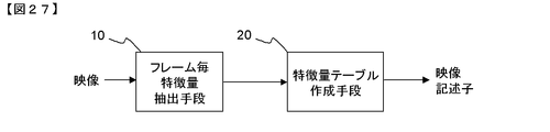
- FIG. 27 is a block diagram showing a video descriptor generation device described in Patent Document 1.
- FIG. 27 is a block diagram showing a video descriptor generation device described in Patent Document 1.
- the frame-by-frame feature quantity extraction means 10 calculates a frame-unit feature quantity from the input video and outputs it to the feature quantity table creation means 20.
- the feature quantity table creation means 20 creates a feature quantity table from the frame unit feature quantity output from the frame-by-frame feature quantity extraction means 10 and outputs it as a video descriptor.
- the frame-by-frame feature quantity extraction means 10 performs processing for extracting feature quantities such as colors for each frame from the input video.
- the obtained feature quantity is output to the feature quantity table creating means 20 as a frame unit feature quantity.
- the feature value table creating means 20 performs threshold value processing on the variation of the feature value between frames and compresses the feature value in the time direction. Specifically, the difference between frames of the frame unit feature value is calculated, and it is determined whether or not it is within a certain allowable variation range. Then, the video is divided into time sections that are within the allowable fluctuation range. For each divided time section, a set of feature amount and time section length (number of frames) is output as a video descriptor.
- the feature amount of the video obtained in units of frames can be compressed in the time direction, and the feature amount size can be reduced. Also, high-speed matching is possible.
- the first problem is that the search accuracy decreases when a black belt region or L-shaped region is added around the video.
- the reason is that there is no means for detecting the addition of a black belt region or L-shaped region and extracting a feature amount.
- black belt areas black areas
- the feature quantity is extracted as it is without being aware of that.
- the feature amount is extracted including the extra black belt region and the L-shaped region, the value of the feature amount is different from that without the feature region, and the search accuracy is lowered.
- An object of the present invention is to provide a video descriptor generation apparatus, method, and program capable of maintaining search accuracy even when a black belt region or an L-shaped region is added to a video.
- a video descriptor generation apparatus is determined by a first extraction unit that extracts a first feature amount for each picture that is a frame or a field of a video, and a boundary between images included in the video.
- a second extracting unit that extracts a second feature amount from the area; and a feature amount integrating unit that generates a video descriptor by combining the first feature amount and the second feature amount.
- the present invention is configured as described above, there is an effect that the search accuracy can be maintained even when a black belt region or an L-shaped region is added to the video.
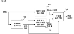
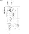
- FIG. 1 there is shown a video descriptor generating apparatus according to a first embodiment of the present invention.
- the video boundary detecting means 100, the visual feature quantity extracting means 120, and the position-corrected visual feature quantity extracting means 130 are shown.
- feature quantity integration means 140 Also is shown.
- the video boundary detection unit 100 calculates the video boundary from the video and outputs the boundary information to the position-corrected visual feature amount extraction unit 130.
- the visual feature quantity extraction unit 120 receives the video, obtains a first feature quantity from the video, and outputs the first feature quantity to the feature quantity integration unit 140.
- the position-corrected visual feature amount extraction unit 130 obtains a second feature amount from the boundary information output from the video boundary detection unit 100 and the video, and outputs the second feature amount to the feature amount integration unit 140.
- the feature quantity integration unit 140 calculates and outputs a video descriptor from the first feature quantity and the second feature quantity.
- the video is input to the visual feature quantity extraction means 120.
- the data is input in units of pictures consisting of frames or fields after being decoded by a decoder.
- the visual feature quantity extraction means 120 calculates a feature quantity vector for each picture.
- a picture is regarded as one still image, and a vector of visual feature quantities indicating features such as colors, patterns, and shapes is extracted.
- the calculated feature quantity vector is output to the feature quantity integration unit 140 as a first feature quantity.
- the video boundary detection means 100 detects whether there is a black belt region or an L-shaped region that is not originally a video, and if it exists, obtains the boundary region.
- the black belt region refers to a black margin region inserted at the top and bottom or the left and right of the screen by 4: 3 and 16: 9 aspect conversion.
- black but not necessarily black.
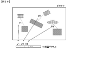
- the L-shaped (or inverted L-shaped) area is a video display technique used when reporting emergency news, etc., by creating a space by slightly reducing the actual video, and then sending breaking news there. is there. In this case, the color is often not black. In any case, it is common in that an area other than the original video is displayed. Examples of these areas are shown in FIG. In FIG. 24, a black area corresponds to a black belt area or an L-shaped area.
- a video presentation technique called Picture or when the camera is shooting a video that is displayed on the screen behind the announcer, can be included in this category because a frame appears around the main video. That is, the system of the present invention can be applied by treating the outside of the area displayed inside in Picture in Picture and the outside of the frame of the screen in the same manner as the black belt area.
- the video boundary detection means 100 obtains such a region that is not included in the original video and the boundary included in the picture.
- the boundary can be calculated by performing a Hough transform on the picture to detect a linear component of the video, and obtaining a linear component that appears at the same position in the picture continuously in time.
- Information describing the obtained video boundary is output to the position-corrected visual feature quantity extraction unit 130 as boundary information.
- the boundary information for example, the distance from the actual edge of the screen to the boundary caused by the black belt region or the L-shaped region can be used. At this time, when a band-like region enters only at the top and bottom, the distance value to the left and right boundaries may be set to zero. Alternatively, when a slightly inclined boundary is allowed, the angle may be described together.
- the boundary information may be a symbol indicating the type of black band or L character, such as L-shaped, horizontal black band, vertical black band, and parameters necessary for describing the band-like area of each pattern. For example, if there are several types of L-shaped widths in advance, a symbol representing an L-shaped pattern and an index for designating the width may be used as boundary information.
- the video is input to the position-corrected visual feature quantity extracting means 130 together with the boundary information in units of pictures.
- the position-corrected visual feature amount extraction unit 130 calculates the feature amount while ignoring the region outside the position determined by the boundary information. That is, the feature amount is extracted by assuming that the area inside the position determined by the boundary information is the entire image.
- the feature quantity to be extracted is the same as the feature quantity extracted by the visual feature quantity extraction unit 120. For example, if the visual feature amount extraction unit 120 extracts a color layout feature amount, the position-corrected visual feature amount extraction unit 130 also extracts a color layout feature amount.
- the extracted feature quantity is output to the feature quantity integration unit 140 as the second feature quantity.
- the feature amount integration unit 140 generates a video descriptor by combining the first feature amount output from the visual feature amount extraction unit 120 and the second feature amount output from the position-corrected visual feature amount extraction unit 130. And output.
- both feature amounts may be simply connected to form one feature amount, or specific encoding may be performed.
- the difference may be encoded using the fact that the correlation between the first feature value and the second feature value is high. This operation will be described in detail below.
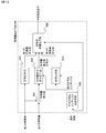
- an embodiment of the feature amount integration unit 140 includes an encoding unit 3 10, an encoding unit 320, and a code string multiplexing unit 230.
- the encoding unit 320 encodes the input first feature quantity, and outputs the obtained first feature quantity code string to the code string multiplexing unit 230.
- the encoding unit 310 encodes the input second feature quantity, and outputs the obtained second feature quantity code string to the code string multiplexing unit 230.
- the code string multiplexing unit 230 generates and outputs a video descriptor by combining the first feature quantity code string and the second feature quantity code string.
- the first feature value is input to the encoding means 320.
- the encoding unit 320 encodes the feature quantity to generate a first feature quantity code string.
- encoding means storing information in a predetermined format, and the values of feature vectors may simply be arranged for each dimension. For example, if the input vector is an N-dimensional integer vector, a format in which N integer values of each dimension are arranged may be used. Alternatively, in the case where the input vector is a floating-point value, quantization may be performed to represent a finite number of representative values, and an index (quantization index) representing the representative value may be arranged. Further, entropy coding may be performed on the obtained integer value or representative value in consideration of the appearance frequency of each value.
- entropy coding Huffman coding or arithmetic coding can be used.
- a process such as entropy coding may be performed after the process of removing the correlation. For example, a difference in values between dimensions having correlation may be obtained and differential encoding may be performed.
- the code sequence may be generated by performing quantization or entropy coding after performing transformation such as frequency transformation on the input feature vector.
- a difference from a feature quantity vector for a past picture may be calculated, and this may be encoded by the above encoding method to generate a code string. .
- the generated first feature amount code string is output to the code string multiplexing unit 230.
- the second feature amount is input to the encoding means 310.
- the operation of the encoding unit 310 is the same as that of the encoding unit 320, and the second feature amount is encoded to generate a second feature amount code string.
- the generated second feature amount code string is output to the code string multiplexing unit 230.
- the code string multiplexing unit 230 multiplexes the first feature quantity code string and the second feature quantity code string to generate a video descriptor.
- the first feature quantity code string and the second feature quantity code string are simply connected with a separable identification code interposed therebetween (however, the code string has a fixed length, When the length is described somewhere, the identification code is not necessary), or the video descriptor may be constructed by interleaving alternately in units of pictures.
- the feature amount integration unit 140 in FIG. 3 can generate a video descriptor having both feature amounts when the feature amount is extracted excluding the black belt region and when the feature amount is extracted using the entire screen. Become.
- an embodiment of the feature quantity integration unit 140 which includes a feature quantity subtraction unit 300, an encoding unit 320, a feature quantity difference encoding unit 340, and a code string multiplexing unit 330.
- the feature amount subtraction unit 300 calculates a difference between the feature amounts by subtracting the first feature amount from the second feature amount, and outputs the feature amount difference value to the feature amount difference encoding unit 340.
- the encoding unit 320 encodes the first feature quantity, and outputs the obtained first feature quantity code string to the code string multiplexing unit 330.
- the feature quantity difference encoding unit 340 encodes the feature quantity difference value output from the feature quantity subtraction unit 300 and outputs the feature quantity difference value code string to the code string multiplexing unit 330.
- the code sequence multiplexing unit 330 generates a video descriptor from the first feature amount code sequence output from the encoding unit 320 and the feature amount difference value code sequence output from the feature amount difference encoding unit 340. ,Output.
- the first feature value is input to the encoding means 320.
- the operation of the encoding unit 320 is the same as that of FIG. 3, and the first feature amount code sequence is output to the code sequence multiplexing unit 330.
- the first feature amount is also input to the feature amount subtracting means 300.
- the second feature amount is also input to the feature amount subtracting means 300.
- the first feature quantity is subtracted from the second feature quantity for each dimension of the feature quantity vector, and a difference vector is calculated.
- This difference vector is output to the feature amount difference encoding means 340 as a feature amount difference value.
- the feature amount difference encoding means 340 encodes the feature amount difference value and generates a feature amount difference value code string.
- the first feature quantity and the second feature quantity have the same correlation as the video, although there is a difference in the presence or absence of the black belt region or the L-shaped region, and therefore there is a strong correlation between the two. For this reason, when the difference between the two feature quantities is calculated, the distribution of the appearing values is considered to be concentrated in the vicinity of zero. Therefore, the amount of codes generated by entropy coding can be reduced using this property.
- a frequency distribution of difference values may be calculated in advance using learning data, and the difference values may be arithmetically encoded using the distribution.
- a Huffman encoding table may be constructed based on the frequency distribution, and the difference value may be encoded based on this table.
- the code string may be configured as a combination of a dimension index having a non-zero value and a code representing a value other than 0.
- the generated feature quantity difference value code string is output to the code string multiplexing means 330.
- the code string multiplexing means 330 connects the first feature quantity code string and the feature quantity difference value code string to generate a video descriptor. The operation is the same as that of the code string multiplexing means 230 in FIG.
- the feature amount integration unit 140 in FIG. 4 can reduce the size of the feature amount by encoding after taking the difference.
- the feature quantity subtraction unit 300 the encoding unit 310, the encoding unit 320, the feature quantity difference encoding unit 340, the code selection unit 520, And code string multiplexing means 530.
- the connection relationship between the feature amount subtracting means 300 and the encoding means 320 is the same as in FIG.
- the feature quantity difference encoding unit 340 encodes the feature quantity difference value output from the feature quantity subtraction unit 300 and outputs the feature quantity difference value code string to the code selection unit 520.
- the encoding unit 310 encodes the second feature quantity and outputs the second feature quantity code string to the code selection unit 520.
- the code selection unit 520 selects one of the feature amount difference value code sequence output from the feature amount difference encoding unit 340 and the second feature amount code sequence output from the encoding unit 310, and the third feature. It outputs to the code string multiplexing means 530 as a quantity code string.
- the code sequence multiplexing means 530 generates a video descriptor from the first feature quantity code sequence output from the encoding means 320 and the third feature quantity code sequence output from the code selection means 520, and outputs the video descriptor. To do.
- the operations of the encoding means 310 and the encoding means 320 are the same as those in FIG.
- the operations of the feature amount subtracting means 300 and the feature amount difference encoding means 340 are the same as those in FIG.
- the feature amount difference value code sequence output from the feature amount difference encoding unit 340 and the second feature amount code sequence output from the encoding unit 310 are input to the code selection unit 520.
- the code selection means 520 compares the code amount between the feature amount difference value code sequence and the second feature amount code sequence in units of pictures or a plurality of pictures, selects a code sequence having a smaller generated code amount,
- the third feature value code string is output to the code string multiplexing means 530.
- information indicating which method is used for encoding is output as mode information to the code string multiplexing means 530 in units of pictures or in units of a plurality of pictures.
- the code string multiplexing means 530 connects the first feature quantity code string and the third feature quantity code string to generate a video descriptor. The operation is almost the same as that of the code string multiplexing unit 230 of FIG. 3, except that the mode information is also included in the video descriptor.
- the feature quantity integration unit 140 of FIG. 6 has a means for encoding the second feature quantity as it is, the feature quantity differs greatly depending on the presence or absence of the black belt area or the L-shaped area, and the feature quantity difference value is encoded. Even if this is not appropriate from the viewpoint of coding efficiency, it is possible to prevent an increase in the feature size.
- the first embodiment of the video descriptor generation device it is possible to extract a video descriptor that can suppress a decrease in search accuracy even when a black belt or an L-shaped region is included.
- the reason is that the black belt region and the L-shaped region are detected, and feature amount information extracted in the region excluding them is included.
- the search accuracy can be maintained by comparing the feature amounts in the regions excluding these.
- a feature amount for the entire video without removing these areas is also held. For this reason, even if a black belt region or an L-shaped region is erroneously detected, matching between the feature amounts of the entire image becomes possible, and accuracy does not decrease.
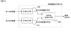
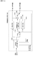
- FIG. 2 there is shown a video descriptor generating apparatus according to a second embodiment of the present invention.
- the video boundary detecting unit 100, the visual feature amount extracting unit 120, and the position-corrected visual feature amount extracting unit 130 are shown.
- feature quantity integration means 240 Also is shown.
- the configuration is almost the same as that in FIG. 1, but a feature amount integration unit 240 is used instead of the feature amount integration unit 140.
- the feature amount integration unit 240 also includes boundary information output from the video boundary detection unit 100. The input points are different.
- the operations of the video boundary detection means 100, the visual feature quantity extraction means 120, and the position-corrected visual feature quantity extraction means 130 are the same as those of the video descriptor generation apparatus in FIG. Then, the first feature amount output from the visual feature amount extraction unit 120 and the second feature amount output from the position-corrected visual feature amount extraction unit 130 are input to the feature amount integration unit 240.
- the boundary information output from the video boundary detection unit 100 is also input to the feature amount integration unit 240.
- the operation of the feature amount integration unit 240 is basically the same as the operation of the feature amount integration unit 140 of FIG. 1, except that the encoding method is controlled by boundary information to generate a video descriptor, and The boundary information or the related information is also included in the video descriptor. Details of this will be described below.
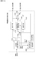
- an embodiment of the feature amount integration unit 240 which includes a feature amount subtraction unit 300, an encoding unit 320, a feature amount difference encoding unit 440, and a code string multiplexing unit 430.
- the connection relationship between the feature amount subtracting means 300 and the encoding means 320 is the same as that in FIG.
- the feature amount difference encoding unit 440 encodes the feature amount difference value from the feature amount difference value output from the feature amount subtracting unit 300 and the boundary information, and the feature amount difference value code string to the code string multiplexing unit 430. Output.
- the code string multiplexing means 430 is a video description based on the first feature quantity code string output from the encoding means 320, the feature quantity difference value code string output from the feature quantity difference encoding means 440, and the boundary information. Create and output children.
- the feature quantity difference encoding means 440 encodes the feature quantity difference value output from the feature quantity subtraction means 300 to generate a feature quantity difference value code string. This operation is basically the same as the operation of the feature amount difference encoding unit 340 described with reference to FIG. However, the feature amount difference encoding unit 440 is different from the feature amount difference encoding unit 340 in that the encoding parameter is controlled by boundary information indicating the black belt region or the L-shaped region. That is, the encoding parameter is changed according to the boundary information. The distribution of the difference value in each dimension of the feature vector changes depending on the size of the black belt region and the L-shaped region, the appearance position, and the like.
- Entropy encoding is performed.
- the generated feature quantity difference value code sequence is output to the code sequence multiplexing means 430.
- the code string multiplexing means 430 multiplexes the first feature quantity code string output from the encoding means 320, the feature quantity difference value code string output from the feature quantity difference encoding means 440, and boundary information. To generate a video descriptor. This operation is basically the same as that of the code string multiplexing means 330 in FIG. 4 except that the boundary information is multiplexed together.
- the boundary information is not the information itself but may be encoded or indexed information.
- encoding parameters such as a Huffman table and a distribution used in arithmetic encoding are classified into several classes, and when one of them is selected and used, What is necessary is just to multiplex the index which identifies this class. Alternatively, a code that can specify this index may be assigned and multiplexed.
- the feature parameter integration unit 240 can optimize the encoding parameter when encoding after taking the difference between the feature parameters, and can improve the encoding efficiency of the feature parameters.
- the connection relationship between the feature amount subtracting means 300 and the encoding means 320 is the same as that in FIG.
- the differential encoding index determination unit 600 receives the boundary information and outputs the differential encoding index to the feature amount differential encoding unit 640 and the encoding unit 610.
- the feature amount difference encoding unit 640 differentially encodes the feature amount difference value output from the feature amount subtraction unit 300 based on the difference encoding index output from the difference encoding index determination unit 600, and the feature amount difference value code The sequence is output to code sequence multiplexing means 630.
- the encoding unit 610 encodes the second feature quantity based on the differential encoding index output from the differential encoding index determination unit 600, and outputs the second feature quantity code sequence to the code sequence multiplexing unit 630.
- the code string multiplexing means 630 outputs the first feature quantity code string output from the encoding means 320, the feature quantity difference value code string output from the feature quantity difference encoding means 640, and the output from the encoding means 610.
- the second feature quantity code string and the boundary information are multiplexed to generate and output a video descriptor.
- the differential encoding index determination means 600 determines a dimension for differential encoding among the dimensions of the feature quantity based on the input boundary information, and outputs an index representing the dimension as a differential encoding index.
- the difference encoding index is output to the feature amount difference encoding unit 640 and the encoding unit 610.
- the feature amount difference encoding means 640 encodes the feature amount difference value for the dimension corresponding to the input difference encoding index, and generates a feature amount difference value code string.
- the encoding method of the feature amount difference value is the same as that of the feature amount difference encoding unit 340 in FIG.
- the generated feature quantity difference value code string is output to the code string multiplexing means 630.
- the encoding unit 610 encodes the second feature quantity for a dimension that does not correspond to the input differential encoding index, and generates a second feature quantity code string.
- the second feature quantity encoding method is the same as that of the encoding means 310 of FIG.
- the generated second feature quantity code string is output to code string multiplexing means 630.
- the first feature value code string output from the encoding means 320 the feature value difference value code string output from the feature quantity difference encoding means 640, and the output from the encoding means 610
- the video descriptor is generated by multiplexing the second feature amount code string and the boundary information. These code strings may be simply connected, or a video descriptor may be constructed by interleaving alternately in units of pictures.
- the multiplexing of the boundary information is the same as that of the code string multiplexing means 430 in FIG.
- the feature amount integration unit 240 in FIG. 7 performs more efficient encoding of feature amounts when there are dimensions where it is better to encode the difference between the feature quantities and dimensions that do not, and changes depending on the boundary information. Will be able to do.
- the feature quantity subtraction unit 300 the encoding unit 320, the differential encoding index determination unit 600, the encoding unit 610, and the feature quantity differential encoding.
- the configuration is such that the code string multiplexing means 830 is used instead of the code string multiplexing means 630, except that a differential coding index is input to the code string multiplexing means 830 instead of boundary information. This is the same as in the case of FIG.
- the feature amount integration unit 240 is shown.
- the feature amount subtraction unit 300, the encoding unit 320, the differential encoding index determination unit 600, the encoding unit 610, and the feature amount differential encoding are illustrated.
- the feature amount difference encoding unit 660 is used instead of the feature amount difference encoding unit 640, and boundary information is also input to the feature amount difference encoding unit 660. Same as the case.
- Operations other than the feature value difference encoding means 660 are the same as those in FIG.
- the operation of the feature amount difference encoding unit 660 is the same as that of the feature amount difference encoding unit 640 of FIG. 7 except that the encoding is performed by changing the encoding parameter according to the boundary information.
- the method of encoding by changing the encoding parameter according to the boundary information is the same as the case of the feature amount difference encoding means 440 in FIG.
- the feature amount subtraction unit 300 the encoding unit 320, the differential encoding index determination unit 600, the encoding unit 310, and the feature amount differential encoding are shown. It comprises means 640, code selection means 720, and code string multiplexing means 730.
- the connection relationship between the feature amount subtracting means 300, the encoding means 320, and the differential encoding index determination means 600 is the same as in the case of FIG.
- the feature amount difference encoding unit 640 differentially encodes the feature amount difference value output from the feature amount subtraction unit 300 based on the difference encoding index output from the difference encoding index determination unit 600, and the feature amount difference value code The column is output to the code selection means 720.
- the encoding unit 310 encodes the second feature quantity and outputs the second feature quantity code string to the code selection unit 720.
- the code selection unit 720 selects a code sequence based on the differential encoding index output from the differential encoding index determination unit 600, and the code sequence multiplexing unit 730 uses the selected code sequence as a third feature amount code sequence. Output to.
- the code string multiplexing means 730 obtains a video descriptor from the first feature quantity code string output from the encoding means 320, the third feature quantity code string output from the code selection means 720, and the boundary information. Generate and output.
- the operations of the feature amount subtraction unit 300, the encoding unit 320, the differential encoding index determination unit 600, and the feature amount difference encoding unit 640 are the same as those in FIG. Further, the operation of the encoding means 310 is the same as in the case of FIG.
- the difference encoding index is calculated for each of the feature amount difference value code sequence output from the feature amount difference encoding unit 640 and the second feature amount code sequence output from the encoding unit 310.
- the sum of code amounts for the dimension corresponding to the differential encoding index output from the determination unit 600 is calculated.
- a code string having a small total code amount is selected.
- the code of the second feature amount code string is selected. This is determined at a predetermined cycle. As this period, for example, a picture or a section composed of a plurality of pictures can be used.
- the selected code string is output to the code string multiplexing means 730 as a third feature value code string.
- information indicating which method is used for encoding is output as mode information to the code string multiplexing means 730 in units of pictures or in units of a plurality of pictures.
- the code sequence multiplexing means 730 the first feature quantity code sequence output from the encoding means 320, the third feature quantity code sequence output from the code selection means 720, boundary information, and mode information are obtained. Multiplexed to generate a video descriptor.
- the multiplexing method is almost the same as in the case of the code string multiplexing means 430 in FIG. 5, except that the mode information is also included in the video descriptor.
- the feature quantity integration unit 240 of FIG. 10 can encode the feature quantity as it is when the feature quantity differential encoding cannot be efficiently performed. Encoding can be performed.
- the feature amount subtraction unit 300 the encoding unit 320, the differential encoding index determination unit 600, the encoding unit 310, and the feature amount differential encoding are illustrated. It comprises means 640, code selection means 720, and code string multiplexing means 930.
- the configuration is such that the code string multiplexing means 930 is used instead of the code string multiplexing means 730, and that the differential encoding index is input to the code string multiplexing means 930 instead of the boundary information. This is the same as in the case of FIG.
- the feature amount subtraction unit 300, the encoding unit 320, the differential encoding index determination unit 600, the encoding unit 310, and the feature amount differential encoding are shown. It comprises means 660, code selection means 720, and code string multiplexing means 730.
- the feature amount difference encoding unit 660 is used instead of the feature amount difference encoding unit 640, and boundary information is also input to the feature amount difference encoding unit 660. Same as the case.
- Operations other than the feature value difference encoding means 660 are the same as those in FIG.
- the operation of the feature amount difference encoding unit 660 is the same as that of the feature amount difference encoding unit 640 of FIG. 10 except that the encoding is performed by changing the encoding parameter according to the boundary information.
- the method of encoding by changing the encoding parameter according to the boundary information is the same as the case of the feature amount difference encoding means 440 in FIG.
- the encoding method of the feature amount can be optimized according to the size of the black belt or the L-shaped region, and the encoding efficiency of the video descriptor can be improved.
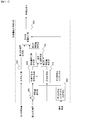
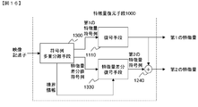
- FIG. 13 an embodiment of a moving image collating apparatus according to the present invention is shown, which comprises feature quantity restoring means 1000, 1010, feature quantity collating means 1020, 1030, 1040, 1050, and selecting means 1060.
- the feature amount restoration unit 1000 receives the first video descriptor, outputs the first feature amount of the separated first video to the feature amount matching unit 1020 and 1030, and outputs the second feature of the first video.
- the feature amount is output to the feature amount matching means 1040 and 1050.
- the feature amount restoring unit 1010 receives the second video descriptor, outputs the first feature amount of the separated second video to the feature amount collating unit 1020, 1040, and outputs the second feature of the second video.
- the feature amount is output to the feature amount matching means 1030 and 1050.
- the feature amount matching unit 1020 receives the first feature amount of the first video and the first feature amount of the second video, and outputs the first matching score to the selection unit 1060.
- the feature amount matching unit 1030 receives the first feature amount of the first video and the second feature amount of the second video, and outputs the second matching score to the selection unit 1060.
- the feature amount matching unit 1040 receives the second feature amount of the first video and the first feature amount of the second video, and outputs a third matching score to the selection unit 1060.
- the feature amount matching unit 1050 receives the second feature amount of the first video and the second feature amount of the second video, and outputs a fourth matching score to the selection unit 1060.
- the selection unit 1060 compares the first collation score to the fourth collation score, selects one, and outputs it as a collation score.
- the first video descriptor is input to the feature amount restoring unit 1000.
- the feature quantity restoration unit 1000 the feature quantity is restored from the first video descriptor, and the first feature quantity of the first video, which is the feature quantity when the black belt area is not removed, and the black belt area are obtained.
- the second feature amount of the first video which is the feature amount when removed, is extracted and output.
- the second video descriptor is input to the feature amount restoration unit 1010, and similarly, the first feature amount of the second video that is the feature amount when the black belt region is not removed, and the black belt.
- the second feature amount of the second video which is the feature amount when the region is removed, is extracted and output. Details of the feature amount restoration in the feature amount restoration units 1000 and 1010 will be described later.
- the first feature amount of the first video and the first feature amount of the second video are input to the feature amount matching unit 1020.
- the feature quantities of the first video and the second video when the black band is not removed are collated.
- feature value values are compared in units of pictures, and a scale representing the distance between feature amounts or the similarity between feature amounts is calculated.
- the distance or similarity of the video section made up of those pictures (the higher the value, the more similar the similarity is. Is calculated).
- a method of calculating the sum or average of values for each picture, calculating a maximum value, or calculating a median value can be considered.
- outliers may be determined in the score of a picture, and statistics such as sum, average, and median may be calculated by excluding them. Thereby, the collation result between video sections is calculated. Hereinafter, this result is referred to as a matching score.
- the calculated matching score is output to the selection unit 1060.
- the operations of the feature quantity matching unit 1030, the feature quantity matching unit 1040, and the feature quantity matching unit 1050 are basically the same as those of the feature quantity matching unit 1020.
- the feature amount matching unit 1030 in order to compare the first feature amount of the first video with the second feature amount of the second video, the case where the black band of the first video is not removed, A collation score with the case where the black band of the second video is removed is calculated.
- the feature amount matching means 1040 in order to compare the second feature amount of the first video with the first feature amount of the second video, the case where the black band of the first video is removed, A collation score is calculated for the case where the black belt of the video is not removed.
- the black bands of the first and second videos are removed.
- the matching score is calculated.
- the collation score is calculated while shifting the picture in the time direction. The reason for collating all combinations of the presence / absence of black band removal in this way is to avoid a decrease in collation accuracy when a black band is erroneously detected by the black band removal process.
- the matching score calculated by the feature amount matching unit 1030, 1040, 1050, 1060 is output to the selection unit 1060.
- the selection means 1060 selects a score having the highest level of matching among the input matching scores. That is, when the collation score is defined by distance, the smallest value is selected, and when the collation score is defined by similarity, the largest value is selected.
- the moving image collation apparatus in FIG. 13 makes it possible to search without reducing the search accuracy even when a black belt region or an L-shape is included.
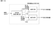
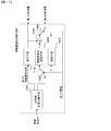
- FIG. 14 there is shown an embodiment of a feature quantity restoration unit 1000 corresponding to the feature quantity integration unit 140 of FIG. 3, which includes a code string demultiplexing unit 1100, a decoding unit 1110, and a decoding unit 1120.
- the code string demultiplexing unit 1100 receives the video descriptor, outputs the separated first feature quantity code sequence to the decoding unit 1110, and outputs the second feature quantity code sequence to the decoding unit 1120.
- the decoding unit 1110 decodes the first feature amount code string output from the code string demultiplexing unit 1100, generates a first feature amount, and outputs the first feature amount.
- the decoding unit 1120 decodes the second feature amount code string output from the code string demultiplexing unit 1100 to generate and output a second feature amount.
- the video descriptor to be collated is first input to the code string demultiplexing means 1100.
- the code string demultiplexing means 1100 separates the first feature value code string and the second feature value code string from the video descriptor by a demultiplexing method according to the method used for multiplexing. For example, in multiplexing, if the first feature quantity code sequence and the second feature quantity code sequence are simply connected with an identification code that can be separated, the identification code is identified, The front is separated as a first feature quantity code string, and the back is separated as a second feature quantity code string.
- a video descriptor is constructed by interleaving alternately in units of pictures, the code string is reconstructed by separating in units of pictures.
- the identification code is identified and separated, and if the length of the code string for each picture is included as header information, Separate by length.
- the first feature quantity code sequence and the second feature quantity code sequence separated in this way are output to the decoding unit 1110 and the decoding unit 1120, respectively.
- the decoding unit 1110 decodes the first feature quantity code string to generate a first feature quantity.
- the decoding method depends on the method used at the time of encoding. For example, when the input vector is an N-dimensional integer vector and the code string is generated in a format in which N integer values of each dimension are arranged, it is only necessary to acquire the N-dimensional vector. When the input vector is quantized and only representative values (quantization indexes) are arranged, inverse quantization may be performed after obtaining the representative values (or representative values obtained from the quantization indexes). Alternatively, when entropy coding is performed, a symbol is obtained by performing decoding corresponding thereto.
- decoding can be performed using the Huffman table used at the time of coding.
- arithmetic decoding can be performed using the symbol frequency distribution used at the time of encoding.
- entropy coding has been performed after removing the correlation between dimensions, first, entropy decoding is performed, and then a restoration process corresponding to the process performed by correlation removal is performed to calculate the feature amount. it can.
- quantization and entropy coding are performed by performing frequency conversion
- the feature amount can be calculated by performing inverse quantization and inverse conversion of frequency conversion after entropy decoding. Further, when the difference from the feature value of the past picture is obtained and encoded, the feature value of the current picture is calculated by adding the value obtained by decoding to the feature value of the past picture.
- the decoding unit 1120 decodes the second feature quantity code string to generate a second feature quantity.
- the operation of the decoding unit 1120 is the same as that of the decoding unit 1110.
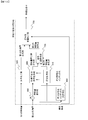
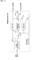
- a feature quantity restoration unit 1000 corresponding to the feature quantity integration unit 140 of FIG. 4 is shown, which includes a code string demultiplexing unit 1200, a decoding unit 1110, a feature quantity difference decoding unit 1230, It comprises feature amount adding means 1240.
- the code string demultiplexing unit 1200 receives the video descriptor, outputs the separated first feature quantity code sequence to the decoding unit 1110, and outputs the feature quantity difference value code sequence to the feature quantity difference decoding unit 1230. .
- the decoding unit 1110 decodes the first feature amount code string output from the code string demultiplexing unit 1200 and outputs the first feature amount.
- the feature amount difference decoding unit 1230 decodes the feature amount difference value code sequence output from the code string demultiplexing unit 1200 and outputs the obtained feature amount difference value to the feature amount addition unit 1240.
- the feature amount adding unit 1240 adds the first feature amount output from the decoding unit 1110 and the feature amount difference value output from the feature amount difference decoding unit 1230, calculates a second feature amount, and outputs it. To do.
- the video descriptor to be collated is first input to the code string demultiplexing means 1200.
- the code string demultiplexing means 1200 separates the first feature value code string and the feature value difference value code string from the video descriptor by a demultiplexing method according to the method used for multiplexing. This operation is the same as that of the code string demultiplexing unit 1100 of the feature amount restoring unit shown in FIG.
- the separated first feature quantity code sequence and feature quantity difference value code string are output to the decoding unit 1110 and the feature quantity difference decoding unit 1230, respectively.
- the operation of the decoding unit 1110 is the same as that in FIG. 14 and outputs the first feature amount.
- the first feature amount is also output to the feature amount addition means 1240.
- the feature amount difference decoding unit 1230 decodes the feature amount difference value code string to obtain a feature amount difference value. Again, decoding is performed by performing the reverse process of the process performed at the time of encoding. For example, when encoding is performed by performing Huffman encoding or arithmetic encoding, decoding is performed by performing a corresponding decoding process. The obtained feature quantity difference value is output to the feature quantity adding means 1240.
- the feature amount adding unit 1240 adds the first feature amount output from the decoding unit 1110 and the feature amount difference value output from the feature amount difference decoding unit 1230 to restore the second feature amount. Then, the obtained second feature amount is output.
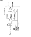
- FIG. 16 there is shown an embodiment of a feature quantity restoring unit 1000 corresponding to the feature quantity integrating unit 240 of FIG. 5, and a code string demultiplexing unit 1300, a decoding unit 1110, a feature quantity difference decoding unit 1330, It comprises feature amount adding means 1240.
- the code string demultiplexing unit 1300 receives the video descriptor, outputs the separated first feature quantity code sequence to the decoding unit 1110, and outputs the feature quantity difference value code series and the boundary information to the feature quantity difference decoding unit. Output to 1330.
- the connection relationship between the decoding unit 1110 and the feature amount addition unit 1240 is the same as that in FIG.
- the feature amount difference decoding unit 1330 decodes the feature amount difference value code sequence output from the code sequence demultiplexing unit 1300 based on the boundary information output from the code sequence demultiplexing unit 1300, and characterizes the feature amount difference value. It outputs to the quantity addition means 1240.
- the decoding unit 1110 decodes the first feature amount code string output from the code string demultiplexing unit 1300, and outputs the first feature amount.
- the feature amount adding unit 1240 adds the first feature amount output from the decoding unit 1110 and the feature amount difference value output from the feature amount difference decoding unit 1330, calculates a second feature amount, and outputs it. To do.
- the video descriptor to be collated is first input to the code string demultiplexing means 1300.
- the operation of the code string demultiplexing means 1300 is the same as that of the code string demultiplexing means 1200 of FIG. 15, but also outputs boundary information. This boundary information is output to the feature amount difference decoding means 1330.
- the operation of the feature quantity difference decoding unit 1330 is basically the same as that of the feature quantity difference decoding unit 1230 in FIG. 15, but the encoding parameter is specified using the input boundary information, and decoding is performed using this parameter. The point is different.
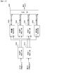
- a feature quantity restoration unit 1000 corresponding to the feature quantity integration unit 140 of FIG. 6 is shown, which includes a code string demultiplexing unit 1400, a decoding unit 1110, a decoding unit 1410, a feature quantity difference.
- the decoding unit 1430 includes a feature amount adding unit 1240, a switching unit 1440, and a switching unit 1450.
- the code string demultiplexing means 1400 receives the video descriptor, outputs the separated first feature quantity code string to the decoding means 1110, and outputs the third feature quantity code string to the switching means 1440. Further, mode information for controlling the switching means is output to the switching means 1440 and the switching means 1450.
- the decoding unit 1110 receives the first feature value code string output from the code string demultiplexing unit 1400, and outputs the first feature value.
- the switching unit 1440 converts the third feature quantity code sequence output from the code sequence demultiplexing unit 1400 into the feature amount difference decoding unit 1430 or the decoding unit 1410 according to the mode information input from the code sequence demultiplexing unit 1400. Output to either one.
- the feature amount difference decoding unit 1430 receives the third feature amount code string output from the switching unit 1440 and outputs the feature amount difference value to the feature amount addition unit 1240.
- the decoding unit 1410 receives the third feature amount code string output from the switching unit 1440 and outputs the decoding result to the switching unit 1450.
- the feature amount adding unit 1240 receives the first feature amount output from the decoding unit 1110 and the feature amount difference value output from the feature amount difference decoding unit 1430, and outputs the addition result to the switching unit 1450. .
- the switching unit 1450 receives the addition result output from the feature amount addition unit 1240 and the decoding result output from the decoding unit 1410 and inputs the second based on the mode information output from the code string demultiplexing unit 1400. Reconstruct and output feature values.
- the video descriptor to be verified is first input to the code string demultiplexing means 1400.
- the code string demultiplexing means 1400 separates the first feature value code string and the third feature value code string from the video descriptor by a demultiplexing method according to the method used for multiplexing. This operation is the same as that of the code string demultiplexing unit 1100 of the feature amount restoring unit shown in FIG.
- the separated first feature value code string and third feature value code string are output to decoding means 1110 and switching means 1440, respectively.
- the mode information is also demultiplexed from the video descriptor and output to the switching unit 1440 and the switching unit 1450.
- the operation of the decoding unit 1110 is the same as that in FIG. 14 and outputs the first feature amount.
- the first feature amount is also output to the feature amount addition means 1240.
- the switching unit 1440 changes the output destination of the third feature quantity code sequence in accordance with the mode information output from the code sequence demultiplexing unit 1400.
- the mode information indicates that the feature quantity included in the third feature quantity code string is a feature quantity difference value
- the third feature quantity code string is output to the feature quantity difference decoding unit 1430.
- the mode information indicates that the feature quantity included in the third feature quantity code string is the second feature quantity
- the third feature quantity code string is output to the decoding unit 1410.
- the timing of switching the output destination based on this mode information depends on how the third feature amount code string is created at the time of encoding. If the entire video is encoded in one mode, the output destination may be set once by mode information first.
- the mode is switched in units of pictures.
- switching is performed in units of a plurality of pictures or when switching is performed in units of regions in a picture, switching is performed in units of the units.
- the feature amount difference decoding unit 1430 decodes the third feature amount code string output from the switching unit 1440 and restores (a part of) the feature amount difference value.
- the operation of the feature quantity difference decoding unit 1430 is basically the same as that of the feature quantity difference decoding unit 1230 of FIG. However, when only a part (for example, only some pictures) of the feature quantity difference value code string is a decoding target in the feature quantity difference decoding unit 1430 depending on the mode, which picture or which region corresponds to it. Information that can identify whether a feature quantity is a decoding target is also included in the third feature quantity code string, and is decoded with reference to this information. The obtained feature quantity difference value is output to the feature quantity adding means 1240.
- the operation of the feature quantity adding means 1240 is the same as that in FIG. 15, and the addition result as the second feature quantity (a part thereof) is output to the switching means 1450.
- the decoding unit 1410 decodes the third feature quantity code string output from the switching unit 1440 and restores (part of) the second feature quantity.
- the operation of the decoding unit 1410 is basically the same as that of the decoding unit 1120 of FIG. However, when only a part (for example, only some pictures) of the third feature quantity code string is a decoding target in the decoding unit 1410 depending on the mode, the feature quantity corresponding to which picture or which area. Is also included in the third feature amount code string, and is decoded with reference to this information.
- the decoding result is output to switching means 1450.
- the switching unit 1450 switches the output source of the second feature amount in accordance with the mode information output from the code string demultiplexing unit 1400.
- the mode information indicates that the feature quantity included in the third feature quantity code string is a feature quantity difference value
- the addition result output from the feature quantity addition unit 1240 is used as the second feature quantity.
- the decoding result output from the decoding unit 1410 is used as the second feature quantity. Output as.
- a feature quantity restoration unit 1000 corresponding to the feature quantity integration unit 240 of FIG. 7 is shown, which includes a code string demultiplexing unit 1500, a decoding unit 1110, a decoding unit 1510, a feature quantity difference.
- the decoding unit 1530 includes a feature amount addition unit 1240, a switching unit 1540, a switching unit 1550, and a differential encoding index determination unit 1560.
- the code string demultiplexing unit 1500 receives the video descriptor, outputs the separated first feature quantity code sequence to the decoding unit 1110, and outputs the third feature quantity code sequence to the switching unit 1540. Further, the boundary information is output to the differential encoding index determination unit 1560.
- the differential encoding index determination unit 1560 receives the boundary information output from the code string demultiplexing unit 1500 and outputs the differential encoding index to the switching unit 1540 and the switching unit 1550.
- the decoding unit 1110 receives the first feature amount code string output from the code string demultiplexing unit 1500 and outputs the first feature amount.
- the switching unit 1540 uses the feature amount difference decoding unit 1530 to decode the third feature amount code sequence output from the code sequence demultiplexing unit 1500 according to the difference encoding index input from the difference encoding index determination unit 1560. Output to one of the means 1510.
- the decoding unit 1510 receives the third feature amount code string output from the switching unit 1540 and outputs the decoding result to the switching unit 1550.
- the feature amount difference decoding unit 1530 receives the third feature amount code string output from the switching unit 1540 and outputs a feature amount difference value to the feature amount addition unit 1240.
- the feature amount addition unit 1240 adds the first feature amount output from the decoding unit 1110 and the feature amount difference value output from the feature amount difference decoding unit 1530, and outputs the addition result to the switching unit 1550.
- the switching unit 1550 receives the addition result output from the feature amount addition unit 1240 and the decoding result output from the decoding unit 1510 as input, and based on the differential encoding index output from the differential encoding index determination unit 1560. The second feature amount is reconstructed and output.
- the video descriptor to be verified is first input to the code string demultiplexing means 1500.
- the code string demultiplexing means 1500 separates the first feature quantity code string and the third feature quantity code string from the video descriptor by a demultiplexing method corresponding to the method used for multiplexing. This operation is the same as that of the code string demultiplexing unit 1100 of the feature amount restoring unit shown in FIG.
- the separated first feature value code string and third feature value code string are output to the decoding unit 1110 and the switching unit 1540, respectively.
- boundary information which is information describing the boundary of the screen formed by the black belt region or the L character, is demultiplexed from the video descriptor and output to the differential encoding index determination means 1560.
- the difference encoding index determining means 1560 is the same as that used at the time of encoding, and among the dimensions of the feature quantity, determines the dimension for performing the difference encoding based on the boundary information, and sets the index representing the dimension as the difference. Output as coding index.
- the operation of the decoding unit 1110 is the same as that in FIG. 14 and outputs the first feature amount.
- the first feature amount is also output to the feature amount addition means 1240.
- the switching means 1540 changes the output destination of the third feature quantity code string in units of feature quantities in accordance with the differential encoding index output from the differential encoding index determination means 1560. For the dimension specified by the differential encoding index, the third feature amount code string is output to the feature amount difference decoding unit 1530. On the other hand, if the dimension is not specified by the differential encoding index, the third feature amount code string is output to the decoding unit 1510.
- the feature quantity difference decoding unit 1530 decodes the third feature quantity code string output from the switching unit 1540, and restores the dimension value specified by the differential encoding index among the feature quantity difference values.
- the operation of the feature amount difference decoding unit 1530 is basically the same as that of the feature amount difference decoding unit 1230 of FIG.
- the obtained feature quantity difference value is output to the feature quantity adding means 1240.
- the operation of the feature amount adding unit 1240 is the same as that in FIG. 15, and the addition result as the second feature amount (a part thereof) is output to the switching unit 1550.
- the decoding unit 1510 decodes the third feature amount code string output from the switching unit 1540, and restores a dimension value not designated by the differential encoding index from the second feature amount.
- the operation of the decoding unit 1510 is basically the same as that of the decoding unit 1120 of FIG.
- the decoding result is output to the switching unit 1550.
- the switching unit 1550 switches the output source of the second feature quantity according to the differential encoding index output from the differential encoding index determination unit 1560.
- the addition result output from the feature amount adding means 1240 is output as the second feature amount.
- the decoding result output from the decoding unit 1510 is output as the second feature amount.
- a feature value restoration unit 1000 corresponding to the feature value integration unit 240 of FIG. 8, which includes a code string demultiplexing unit 1600, a decoding unit 1110, a decoding unit 1510, and a feature amount difference.
- the decoding unit 1530 includes a feature amount addition unit 1240, a switching unit 1540, and a switching unit 1550.
- the configuration is the same as that of FIG. 18 except for the code string demultiplexing unit 1600, the switching unit 1540, and the switching unit 1550.
- the code string demultiplexing unit 1600 receives the video descriptor, outputs the separated first feature quantity code sequence to the decoding unit 1110, and outputs the third feature quantity code sequence to the switching unit 1540. Also, the differential encoding index is output to the switching unit 1540 and the switching unit 1550.
- the switching unit 1540 uses the feature amount difference decoding unit 1530 or the decoding unit to convert the third feature amount code sequence output from the code sequence demultiplexing unit 1500 according to the differential encoding index output from the code sequence demultiplexing unit 1600. Output to either one of 1510.
- the switching unit 1550 receives the addition result output from the feature amount addition unit 1240 and the decoding result output from the decoding unit 1510 as input, and based on the differential encoding index output from the code string demultiplexing unit 1600 The feature quantity 2 is reconstructed and output.
- a feature value restoration unit 1000 corresponding to the feature value integration unit 240 of FIG. 9 is shown, which includes a code string demultiplexing unit 1500, a decoding unit 1110, a decoding unit 1510, and a feature amount difference.
- the decoding unit 1730, the feature amount addition unit 1240, the switching unit 1540, and the switching unit 1550 are included.
- the connection relationship other than the code string demultiplexing means 1500 and the feature quantity difference decoding means 1730 is the same as in the case of FIG.
- the code string demultiplexing unit 1500 receives the video descriptor, outputs the separated first feature quantity code sequence to the decoding unit 1110, and outputs the third feature quantity code sequence to the switching unit 1540. Further, the boundary information is output to the differential encoding index determination unit 1560 and the feature amount difference decoding unit 1730.
- the feature amount difference decoding unit 1730 receives the third feature amount code string output from the switching unit 1540 and the boundary information output from the code sequence demultiplexing unit 1500, and uses the feature amount difference value as the feature amount addition unit 1240. Output to.
- Operations other than the feature amount difference decoding unit 1730 are the same as those in FIG.
- the operation of the feature amount difference decoding unit 1730 is the same as that of the feature amount difference decoding unit 1530 in FIG. 18 except that the decoding is performed by changing the encoding parameter according to the boundary information.
- a feature quantity restoration unit 1000 corresponding to the feature quantity integration unit 240 of FIG. 10 is shown, which includes a code string demultiplexing unit 1700, a decoding unit 1110, a decoding unit 1510, and a feature quantity difference.
- the decoding unit 1530 includes a feature amount addition unit 1240, a switching unit 1740, a switching unit 1750, and a differential encoding index determination unit 1560.
- the connection relationship between the decoding unit 1110, the decoding unit 1510, the feature amount difference decoding unit 1530, and the feature amount addition unit 1240 is the same as that in FIG.
- the code string demultiplexing unit 1700 receives the video descriptor, outputs the separated first feature quantity code sequence to the decoding unit 1110, and outputs the third feature quantity code sequence to the switching unit 1740. Further, the boundary information is output to the differential encoding index determination unit 1560 and the mode information is output to the switching unit 1740 and the switching unit 1750.
- the differential encoding index determination unit 1560 receives the boundary information output from the code string demultiplexing unit 1700 and outputs the differential encoding index to the switching unit 1740 and the switching unit 1750.
- the switching unit 1740 outputs the third code output from the code sequence demultiplexing unit 1700 according to the differential encoding index output from the differential encoding index determining unit 1560 and the mode information output from the code sequence demultiplexing unit 1700. Is output to either the feature amount difference decoding unit 1530 or the decoding unit 1510.
- the switching unit 1750 receives the addition result output from the feature amount addition unit 1240 and the decoding result output from the decoding unit 1510 as input, the differential encoding index output from the differential encoding index determination unit 1560, and the code Based on the mode information output from the column demultiplexing means 1700, the second feature value is reconstructed and output.
- the video descriptor to be verified is first input to the code string demultiplexing means 1700.
- the code string demultiplexing means 1700 separates the first feature value code string and the third feature value code string from the video descriptor by a demultiplexing method according to the method used for multiplexing. This operation is the same as that of the code string demultiplexing unit 1100 of the feature amount restoring unit shown in FIG.
- the separated first feature value code string and third feature value code string are output to decoding means 1110 and switching means 1740, respectively.
- boundary information which is information describing the boundary of the screen formed by the black belt region or the L character, is demultiplexed from the video descriptor and output to the differential encoding index determination means 1560.
- the mode information is also demultiplexed from the video descriptor and output to the switching unit 1740 and the switching unit 1750.
- the operation of the differential encoding index determination means 1560 is the same as that in FIG. 18 and outputs a differential encoding index.
- the operation of the decoding unit 1110 is the same as that in FIG. 14 and outputs the first feature amount.
- the first feature amount is also output to the feature amount addition means 1240.
- the output destination of the third feature quantity code string is set in accordance with the differential coding index output from the differential coding index determination means 1560 and the mode information output from the code string demultiplexing means 1700. Change in dimension units of features.
- the mode information indicates that the feature quantity included in the third feature quantity code string is a feature quantity difference value
- the third feature is provided for the dimension specified by the differential encoding index.
- the quantity code string is output to the feature quantity difference decoding unit 1530. If the dimension is not designated by the differential encoding index, the third feature quantity code string is output to the decoding unit 1510.
- the mode information indicates that the feature quantity included in the third feature quantity code sequence is the second feature quantity
- the third feature quantity code sequence is output to the decoding unit 1510.
- the operations of the feature amount difference decoding unit 1530, the feature amount addition unit 1240, and the decoding unit 1510 are the same as those in FIG.
- the switching unit 1750 switches the output source of the second feature amount according to the differential encoding index output from the differential encoding index determination unit 1560 and the mode information output from the code string demultiplexing unit 1700.
- the mode information indicates that the feature amount included in the third feature amount code string is a feature amount difference value, in the case of the dimension included in the differential encoding index, the feature amount addition unit 1240 The addition result output from is output as a second feature value, and in the case of dimensions not included in the differential encoding index, the decoding result output from the decoding unit 1510 is output as the second feature value.
- the mode information indicates that the feature quantity included in the third feature quantity code string is the second feature quantity
- the decoding result output from the decoding unit 1510 is used as the second feature quantity. Output as.
- 21 provides means for separating feature quantities integrated by the feature quantity integration means 240 shown in FIG.
- a feature quantity restoration unit 1000 corresponding to the feature quantity integration unit 240 of FIG. 11 is shown, which includes a code string demultiplexing unit 1800, a decoding unit 1110, a decoding unit 1510, and a feature quantity difference.
- the decoding unit 1530 includes a feature amount addition unit 1240, a switching unit 1740, and a switching unit 1750.
- the configuration is the same as that of FIG. 20 except for the code string demultiplexing means 1800, the switching means 1740, and the switching means 1750.
- the code string demultiplexing unit 1800 receives the video descriptor, outputs the separated first feature quantity code sequence to the decoding unit 1110, and outputs the third feature quantity code sequence to the switching unit 1540. Also, the differential encoding index and the mode information are output to the switching unit 1740 and the switching unit 1750.
- the switching unit 1740 converts the third feature amount code string output from the code sequence demultiplexing unit 1800 into the feature amount difference decoding unit 1530 according to the differential encoding index and mode information output from the code sequence demultiplexing unit 1800. Or the decoding unit 1510.
- the switching unit 1750 receives the addition result output from the feature amount addition unit 1240 and the decoding result output from the decoding unit 1510 as input, and is based on the differential encoding index output from the code string demultiplexing unit 1800 and the mode information. The second feature value is reconstructed and output.
- a feature quantity restoration unit 1000 corresponding to the feature quantity integration unit 240 of FIG. 12 is shown, which includes a code string demultiplexing unit 1700, a decoding unit 1110, a decoding unit 1510, and a feature quantity difference.
- the decoding unit 1530 includes a feature amount addition unit 1240, a switching unit 1740, a switching unit 1750, and a differential encoding index determination unit 1560.
- the connection relationships other than the code string demultiplexing means 1700 and the feature quantity difference decoding means 1730 are the same as those in FIG.
- the code sequence demultiplexing unit 1700 receives the video descriptor, outputs the separated first feature quantity code sequence to the decoding unit 1110, and outputs the third feature quantity code sequence to the switching unit 1540. Further, the boundary information is output to the differential encoding index determination unit 1560 and the feature amount difference decoding unit 1730, and the mode information is output to the switching unit 1740 and the switching unit 1750.
- the feature amount difference decoding unit 1730 receives the third feature amount code string output from the switching unit 1740 and the boundary information output from the code sequence demultiplexing unit 1700, and uses the feature amount difference value as the feature amount addition unit 1240. Output to.
- Operations other than the feature value difference decoding unit 1730 are the same as those in FIG.
- the operation of the feature quantity difference decoding unit 1730 is the same as that of the feature quantity difference decoding unit 1530 in FIG. 21 except that decoding is performed by changing the encoding parameter according to the boundary information.
- the above is the description of the embodiment of the moving image matching apparatus. According to this embodiment, it is possible to collate moving images based on the video descriptor extracted by the above-described video descriptor generation apparatus. That is, even when there is a black belt or an L-shaped region, it is possible to collate without reducing accuracy.
- FIG. 26 shows an example of a method for extracting feature values from a picture.
- two arbitrary regions in a picture are previously determined as a pair, and a feature amount difference between the paired two regions is used as a feature vector.
- each region pair is represented as P1, P2, P3,...
- a feature amount determined from the nth pair Pn is represented as Vn.
- Vn a feature amount determined from the nth pair Pn.
- Various methods for obtaining Vn from Pn are conceivable. For example, there is a method in which an average value of luminance is calculated in each paired area and shaded area and a value of Vn is determined based on the magnitude relationship.
- 0 may be used when the absolute value of the difference is smaller than the threshold value, and Vn may be expressed as a ternary value.
- Vn is ternary.
- the video boundary detection means 100 performs a Hough transform on each picture and detects a horizontal or vertical straight line close to the edge of the video. Next, the continuity between pictures is measured, and when it continues with pictures that are equal to or greater than the threshold, it is detected as a boundary of a black belt region or an L-shaped region, and boundary information is output.
- the position-corrected visual feature quantity extraction unit 130 regards the area excluding the boundary area as a full screen and performs the same processing as the visual feature quantity extraction unit 120 to obtain an N-dimensional feature quantity vector V′n.
- the feature quantity integration unit 140 or 240 integrates N-dimensional feature quantity vectors Vn and V′n obtained for each picture to generate a video descriptor.
- the video descriptor generating apparatus and the moving image collating apparatus can be realized by a computer and a program as well as by realizing the functions of the apparatus.
- the program is provided by being recorded on a computer-readable recording medium such as a magnetic disk or a semiconductor memory, and is read by the computer at the time of starting up the computer, etc. It functions as a video descriptor generation device and a moving image collation device in the form.
- the present invention can be applied to a use such as searching for a similar or identical video from many videos with high accuracy.
- the search for the same section of video can be used for the purpose of identifying an illegally copied moving image distributed on the network, or for the purpose of identifying a CM being broadcast by an actual broadcast wave.
- DESCRIPTION OF SYMBOLS 10 Frame feature-value extraction means 20 ... Feature-value table preparation means 100 ... Image
- feature quantity difference coding means 660 ... feature quantity difference coding means 720 ... code string selection means 730 ... Code string multiplexing means 830 ... code string multiplexing means 930 ... code string multiplexing means 1000 ... feature quantity restoring means 1010 ... feature quantity restoring means 020 ... Feature quantity matching means 1030 ... Feature quantity matching means 1040 ... Feature quantity matching means 1050 ... Feature quantity matching means 1060 ... Selection means 1100 ... Code string demultiplexing means 1110 ... Decoding means 1120 ... Decoding means 1200 ... Code string demultiplexing means 1230 ... Feature quantity difference decoding means 1240 ... Feature quantity addition means 1300 ... Code string demultiplexing means 1330 ...
- Feature quantity difference decoding means 1400 ... Code string demultiplexing means 1410 ... Decoding means 1430 ... Feature quantity difference decoding means 1440 ... Switching means 1450 ... switching means 1500 ... code string demultiplexing means 1510 ... decoding means 1530 ... feature quantity difference decoding means 1540 ... switching means 1550 ... switching means 1560 ... differential coding index determining means 1600 ... code string demultiplexing means 1700 ... code string demultiplexing Means 1730: Feature amount difference No. 1740 ... switching means 1750 ... switching means 1800 ... code sequence demultiplexing means
Landscapes
- Engineering & Computer Science (AREA)
- Theoretical Computer Science (AREA)
- Multimedia (AREA)
- Physics & Mathematics (AREA)
- General Physics & Mathematics (AREA)
- Library & Information Science (AREA)
- Databases & Information Systems (AREA)
- Data Mining & Analysis (AREA)
- General Engineering & Computer Science (AREA)
- Computer Vision & Pattern Recognition (AREA)
- Mathematical Physics (AREA)
- Computational Linguistics (AREA)
- Signal Processing (AREA)
- Compression Or Coding Systems Of Tv Signals (AREA)
- Television Signal Processing For Recording (AREA)
- Information Retrieval, Db Structures And Fs Structures Therefor (AREA)
- Closed-Circuit Television Systems (AREA)
- Image Analysis (AREA)
- Image Processing (AREA)
Abstract
Priority Applications (6)
| Application Number | Priority Date | Filing Date | Title |
|---|---|---|---|
| JP2010547432A JP4883226B2 (ja) | 2009-01-23 | 2010-01-20 | 映像記述子生成装置 |
| US13/144,758 US9367616B2 (en) | 2009-01-23 | 2010-01-20 | Video descriptor generation device |
| CN201080005232.6A CN102292979B (zh) | 2009-01-23 | 2010-01-20 | 视频描述符生成装置 |
| EP10733345A EP2391122A4 (fr) | 2009-01-23 | 2010-01-20 | Dispositif pour générer un descripteur vidéo |
| KR20117017376A KR101289928B1 (ko) | 2009-01-23 | 2010-01-20 | 비디오 디스크립터 생성 디바이스 |
| EP11189661.9A EP2434416B1 (fr) | 2009-01-23 | 2010-01-20 | Dispositif pour générer un descripteur vidéo |
Applications Claiming Priority (2)
| Application Number | Priority Date | Filing Date | Title |
|---|---|---|---|
| JP2009-012812 | 2009-01-23 | ||
| JP2009012812 | 2009-01-23 |
Publications (1)
| Publication Number | Publication Date |
|---|---|
| WO2010084737A1 true WO2010084737A1 (fr) | 2010-07-29 |
Family
ID=42355795
Family Applications (1)
| Application Number | Title | Priority Date | Filing Date |
|---|---|---|---|
| PCT/JP2010/000276 WO2010084737A1 (fr) | 2009-01-23 | 2010-01-20 | Dispositif pour générer un descripteur vidéo |
Country Status (6)
| Country | Link |
|---|---|
| US (1) | US9367616B2 (fr) |
| EP (2) | EP2391122A4 (fr) |
| JP (2) | JP4883226B2 (fr) |
| KR (1) | KR101289928B1 (fr) |
| CN (2) | CN102292979B (fr) |
| WO (1) | WO2010084737A1 (fr) |
Cited By (3)
| Publication number | Priority date | Publication date | Assignee | Title |
|---|---|---|---|---|
| US9367616B2 (en) | 2009-01-23 | 2016-06-14 | Nec Corporation | Video descriptor generation device |
| JP2017143425A (ja) * | 2016-02-10 | 2017-08-17 | 三菱電機株式会社 | 画像特徴記述子符号化装置、画像特徴記述子復号装置、画像特徴記述子符号化方法及び画像特徴記述子復号方法 |
| CN110758354A (zh) * | 2019-10-16 | 2020-02-07 | 刘志方 | 基于大数据采集的车辆紧急制动执行系统 |
Families Citing this family (13)
| Publication number | Priority date | Publication date | Assignee | Title |
|---|---|---|---|---|
| US9258564B2 (en) * | 2012-02-07 | 2016-02-09 | Stmicroelectronics S.R.L. | Visual search system architectures based on compressed or compact feature descriptors |
| CN108197631B (zh) * | 2012-07-23 | 2022-06-28 | 苹果公司 | 提供图像特征描述符的方法 |
| CN104144520A (zh) | 2013-05-07 | 2014-11-12 | 李东舸 | 一种设备间建立连接的方法、装置与系统 |
| CN104142939B (zh) * | 2013-05-07 | 2019-07-02 | 杭州智棱科技有限公司 | 一种基于运动特征信息匹配特征码的方法与设备 |
| EP3092796B1 (fr) | 2014-01-07 | 2020-06-17 | Canon Kabushiki Kaisha | Procédé, appareil et programme informatique pour codage de données de dépendance intercouches |
| JP6334735B2 (ja) * | 2014-05-06 | 2018-05-30 | ナント・ホールデイングス・アイ・ピー・エル・エル・シー | エッジベクトルを利用した画像特徴検出 |
| US9544621B2 (en) | 2014-09-17 | 2017-01-10 | Google Inc. | Identification of captured videos |
| US10095786B2 (en) | 2015-04-09 | 2018-10-09 | Oath Inc. | Topical based media content summarization system and method |
| CN106028158B (zh) * | 2016-05-26 | 2019-04-16 | 成都掌中全景信息技术有限公司 | 一种基于多视频源的进度识别方法 |
| JP6530002B2 (ja) * | 2017-04-12 | 2019-06-12 | 日本電信電話株式会社 | コンテンツ探索装置、コンテンツ探索方法、プログラム |
| CN108876813B (zh) * | 2017-11-01 | 2021-01-26 | 北京旷视科技有限公司 | 用于视频中物体检测的图像处理方法、装置及设备 |
| US11263261B2 (en) * | 2020-02-14 | 2022-03-01 | Alibaba Group Holding Limited | Method and system for characteristic-based video processing |
| CN113810695A (zh) * | 2020-06-15 | 2021-12-17 | 中国电信股份有限公司 | 视频编码方法、装置及计算机可读存储介质 |
Citations (5)
| Publication number | Priority date | Publication date | Assignee | Title |
|---|---|---|---|---|
| JPH10320400A (ja) | 1997-05-16 | 1998-12-04 | Hitachi Ltd | 映像の検索方法および装置 |
| JP2003122758A (ja) * | 2001-10-11 | 2003-04-25 | Canon Inc | 画像検索方法及び装置 |
| JP2004172671A (ja) * | 2002-11-15 | 2004-06-17 | Toshiba Corp | 動画像加工方法及び装置 |
| JP2007047943A (ja) * | 2005-08-08 | 2007-02-22 | Canon Inc | 画像処理装置及びその制御方法、プログラム |
| JP2009012812A (ja) | 2007-07-05 | 2009-01-22 | Sekisui Film Kk | 合成樹脂フィルム |
Family Cites Families (12)
| Publication number | Priority date | Publication date | Assignee | Title |
|---|---|---|---|---|
| JP2002117037A (ja) * | 2000-10-06 | 2002-04-19 | Nec Corp | 画像検索装置、並びに画像検索方法及びこれが書き込まれた記録媒体 |
| JP2003319177A (ja) * | 2002-04-22 | 2003-11-07 | Canon Inc | 量子化処理装置及び方法とそれを用いたインクジェット記録装置 |
| US7321623B2 (en) * | 2002-10-01 | 2008-01-22 | Avocent Corporation | Video compression system |
| US7657126B2 (en) * | 2005-05-09 | 2010-02-02 | Like.Com | System and method for search portions of objects in images and features thereof |
| US8145656B2 (en) * | 2006-02-07 | 2012-03-27 | Mobixell Networks Ltd. | Matching of modified visual and audio media |
| CN101473657A (zh) * | 2006-06-20 | 2009-07-01 | 皇家飞利浦电子股份有限公司 | 产生视频信号的指纹 |
| US8676810B2 (en) * | 2006-07-31 | 2014-03-18 | Ricoh Co., Ltd. | Multiple index mixed media reality recognition using unequal priority indexes |
| US8355569B2 (en) * | 2006-08-10 | 2013-01-15 | Nec Corporation | Object region extracting device |
| CN101548294B (zh) * | 2006-11-30 | 2012-06-27 | 杜比实验室特许公司 | 提取视频和音频信号内容的特征以提供信号的可靠识别 |
| US8498487B2 (en) * | 2008-08-20 | 2013-07-30 | Sri International | Content-based matching of videos using local spatio-temporal fingerprints |
| KR101289928B1 (ko) | 2009-01-23 | 2013-07-25 | 닛본 덴끼 가부시끼가이샤 | 비디오 디스크립터 생성 디바이스 |
| US8260055B2 (en) * | 2009-03-27 | 2012-09-04 | The Nielsen Company (Us), Llc | Methods and apparatus for identifying primary media content in a post-production media content presentation |
-
2010
- 2010-01-20 KR KR20117017376A patent/KR101289928B1/ko active IP Right Grant
- 2010-01-20 EP EP10733345A patent/EP2391122A4/fr not_active Ceased
- 2010-01-20 US US13/144,758 patent/US9367616B2/en active Active
- 2010-01-20 CN CN201080005232.6A patent/CN102292979B/zh not_active Expired - Fee Related
- 2010-01-20 CN CN201510047532.5A patent/CN104537127B/zh not_active Expired - Fee Related
- 2010-01-20 WO PCT/JP2010/000276 patent/WO2010084737A1/fr active Application Filing
- 2010-01-20 EP EP11189661.9A patent/EP2434416B1/fr not_active Not-in-force
- 2010-01-20 JP JP2010547432A patent/JP4883226B2/ja not_active Expired - Fee Related
-
2011
- 2011-11-30 JP JP2011262738A patent/JP2012084164A/ja active Pending
Patent Citations (5)
| Publication number | Priority date | Publication date | Assignee | Title |
|---|---|---|---|---|
| JPH10320400A (ja) | 1997-05-16 | 1998-12-04 | Hitachi Ltd | 映像の検索方法および装置 |
| JP2003122758A (ja) * | 2001-10-11 | 2003-04-25 | Canon Inc | 画像検索方法及び装置 |
| JP2004172671A (ja) * | 2002-11-15 | 2004-06-17 | Toshiba Corp | 動画像加工方法及び装置 |
| JP2007047943A (ja) * | 2005-08-08 | 2007-02-22 | Canon Inc | 画像処理装置及びその制御方法、プログラム |
| JP2009012812A (ja) | 2007-07-05 | 2009-01-22 | Sekisui Film Kk | 合成樹脂フィルム |
Non-Patent Citations (1)
| Title |
|---|
| See also references of EP2391122A4 |
Cited By (3)
| Publication number | Priority date | Publication date | Assignee | Title |
|---|---|---|---|---|
| US9367616B2 (en) | 2009-01-23 | 2016-06-14 | Nec Corporation | Video descriptor generation device |
| JP2017143425A (ja) * | 2016-02-10 | 2017-08-17 | 三菱電機株式会社 | 画像特徴記述子符号化装置、画像特徴記述子復号装置、画像特徴記述子符号化方法及び画像特徴記述子復号方法 |
| CN110758354A (zh) * | 2019-10-16 | 2020-02-07 | 刘志方 | 基于大数据采集的车辆紧急制动执行系统 |
Also Published As
| Publication number | Publication date |
|---|---|
| US9367616B2 (en) | 2016-06-14 |
| CN102292979B (zh) | 2015-02-04 |
| EP2434416B1 (fr) | 2018-08-15 |
| EP2434416A3 (fr) | 2012-08-29 |
| EP2434416A2 (fr) | 2012-03-28 |
| CN104537127B (zh) | 2018-04-10 |
| JP2012084164A (ja) | 2012-04-26 |
| CN102292979A (zh) | 2011-12-21 |
| CN104537127A (zh) | 2015-04-22 |
| JP4883226B2 (ja) | 2012-02-22 |
| EP2391122A4 (fr) | 2012-09-05 |
| JPWO2010084737A1 (ja) | 2012-07-12 |
| EP2391122A1 (fr) | 2011-11-30 |
| US20110274355A1 (en) | 2011-11-10 |
| KR20110106414A (ko) | 2011-09-28 |
| KR101289928B1 (ko) | 2013-07-25 |
Similar Documents
| Publication | Publication Date | Title |
|---|---|---|
| JP4883226B2 (ja) | 映像記述子生成装置 | |
| JP4725690B2 (ja) | 映像識別子抽出装置 | |
| CN102187672B (zh) | 压缩视频中的语法元素的兼容cabac/avc的水印加注 | |
| JP4687834B2 (ja) | 映像記述子生成装置 | |
| TW201304554A (zh) | 影像編碼方法、影像解碼方法、影像編碼裝置、影像解碼裝置、影像編碼程式及影像解碼程式 | |
| KR20140058643A (ko) | 강건한 낮은 복잡도 비디오 핑거프린팅을 위한 장치 및 방법 | |
| CN111434115A (zh) | 视频编码中纹理合成的聚类修正 | |
| US10445613B2 (en) | Method, apparatus, and computer readable device for encoding and decoding of images using pairs of descriptors and orientation histograms representing their respective points of interest | |
| JP5644505B2 (ja) | 照合加重情報抽出装置 | |
| JP4167245B2 (ja) | デジタル映像処理方法及びその装置 | |
| CN105847822A (zh) | 一种视频解码方法及装置 | |
| JP2005303738A (ja) | 画像処理装置 | |
| JP2015041796A (ja) | 画像処理方法、画像処理装置、画像処理プログラム、およびデータ構造 | |
| JP2005175943A (ja) | 画像処理装置、画像処理方法、コンピュータプログラム及び記録媒体 | |
| JP2007243512A (ja) | 画像処理装置および画像処理プログラム |
Legal Events
| Date | Code | Title | Description |
|---|---|---|---|
| WWE | Wipo information: entry into national phase |
Ref document number: 201080005232.6 Country of ref document: CN |
|
| 121 | Ep: the epo has been informed by wipo that ep was designated in this application |
Ref document number: 10733345 Country of ref document: EP Kind code of ref document: A1 |
|
| ENP | Entry into the national phase |
Ref document number: 2010547432 Country of ref document: JP Kind code of ref document: A |
|
| WWE | Wipo information: entry into national phase |
Ref document number: 13144758 Country of ref document: US |
|
| WWE | Wipo information: entry into national phase |
Ref document number: 2010733345 Country of ref document: EP |
|
| ENP | Entry into the national phase |
Ref document number: 20117017376 Country of ref document: KR Kind code of ref document: A |
|
| NENP | Non-entry into the national phase |
Ref country code: DE |