EP2434416B1 - Dispositif pour générer un descripteur vidéo - Google Patents
Dispositif pour générer un descripteur vidéo Download PDFInfo
- Publication number
- EP2434416B1 EP2434416B1 EP11189661.9A EP11189661A EP2434416B1 EP 2434416 B1 EP2434416 B1 EP 2434416B1 EP 11189661 A EP11189661 A EP 11189661A EP 2434416 B1 EP2434416 B1 EP 2434416B1
- Authority
- EP
- European Patent Office
- Prior art keywords
- feature
- video
- code sequence
- unit
- encoding
- Prior art date
- Legal status (The legal status is an assumption and is not a legal conclusion. Google has not performed a legal analysis and makes no representation as to the accuracy of the status listed.)
- Not-in-force
Links
Images


Classifications
-
- G—PHYSICS
- G06—COMPUTING; CALCULATING OR COUNTING
- G06F—ELECTRIC DIGITAL DATA PROCESSING
- G06F16/00—Information retrieval; Database structures therefor; File system structures therefor
- G06F16/70—Information retrieval; Database structures therefor; File system structures therefor of video data
-
- H—ELECTRICITY
- H04—ELECTRIC COMMUNICATION TECHNIQUE
- H04N—PICTORIAL COMMUNICATION, e.g. TELEVISION
- H04N5/00—Details of television systems
- H04N5/76—Television signal recording
-
- G—PHYSICS
- G06—COMPUTING; CALCULATING OR COUNTING
- G06F—ELECTRIC DIGITAL DATA PROCESSING
- G06F16/00—Information retrieval; Database structures therefor; File system structures therefor
- G06F16/50—Information retrieval; Database structures therefor; File system structures therefor of still image data
- G06F16/58—Retrieval characterised by using metadata, e.g. metadata not derived from the content or metadata generated manually
- G06F16/583—Retrieval characterised by using metadata, e.g. metadata not derived from the content or metadata generated manually using metadata automatically derived from the content
- G06F16/5838—Retrieval characterised by using metadata, e.g. metadata not derived from the content or metadata generated manually using metadata automatically derived from the content using colour
-
- G—PHYSICS
- G06—COMPUTING; CALCULATING OR COUNTING
- G06F—ELECTRIC DIGITAL DATA PROCESSING
- G06F16/00—Information retrieval; Database structures therefor; File system structures therefor
- G06F16/50—Information retrieval; Database structures therefor; File system structures therefor of still image data
- G06F16/58—Retrieval characterised by using metadata, e.g. metadata not derived from the content or metadata generated manually
- G06F16/583—Retrieval characterised by using metadata, e.g. metadata not derived from the content or metadata generated manually using metadata automatically derived from the content
- G06F16/5854—Retrieval characterised by using metadata, e.g. metadata not derived from the content or metadata generated manually using metadata automatically derived from the content using shape and object relationship
-
- G—PHYSICS
- G06—COMPUTING; CALCULATING OR COUNTING
- G06F—ELECTRIC DIGITAL DATA PROCESSING
- G06F16/00—Information retrieval; Database structures therefor; File system structures therefor
- G06F16/70—Information retrieval; Database structures therefor; File system structures therefor of video data
- G06F16/73—Querying
- G06F16/732—Query formulation
- G06F16/7328—Query by example, e.g. a complete video frame or video sequence
-
- G—PHYSICS
- G06—COMPUTING; CALCULATING OR COUNTING
- G06F—ELECTRIC DIGITAL DATA PROCESSING
- G06F16/00—Information retrieval; Database structures therefor; File system structures therefor
- G06F16/70—Information retrieval; Database structures therefor; File system structures therefor of video data
- G06F16/78—Retrieval characterised by using metadata, e.g. metadata not derived from the content or metadata generated manually
- G06F16/783—Retrieval characterised by using metadata, e.g. metadata not derived from the content or metadata generated manually using metadata automatically derived from the content
- G06F16/7847—Retrieval characterised by using metadata, e.g. metadata not derived from the content or metadata generated manually using metadata automatically derived from the content using low-level visual features of the video content
-
- G—PHYSICS
- G06—COMPUTING; CALCULATING OR COUNTING
- G06V—IMAGE OR VIDEO RECOGNITION OR UNDERSTANDING
- G06V10/00—Arrangements for image or video recognition or understanding
- G06V10/40—Extraction of image or video features
- G06V10/42—Global feature extraction by analysis of the whole pattern, e.g. using frequency domain transformations or autocorrelation
- G06V10/421—Global feature extraction by analysis of the whole pattern, e.g. using frequency domain transformations or autocorrelation by analysing segments intersecting the pattern
-
- G—PHYSICS
- G06—COMPUTING; CALCULATING OR COUNTING
- G06V—IMAGE OR VIDEO RECOGNITION OR UNDERSTANDING
- G06V10/00—Arrangements for image or video recognition or understanding
- G06V10/40—Extraction of image or video features
- G06V10/50—Extraction of image or video features by performing operations within image blocks; by using histograms, e.g. histogram of oriented gradients [HoG]; by summing image-intensity values; Projection analysis
-
- G—PHYSICS
- G06—COMPUTING; CALCULATING OR COUNTING
- G06V—IMAGE OR VIDEO RECOGNITION OR UNDERSTANDING
- G06V20/00—Scenes; Scene-specific elements
- G06V20/40—Scenes; Scene-specific elements in video content
- G06V20/46—Extracting features or characteristics from the video content, e.g. video fingerprints, representative shots or key frames
-
- H—ELECTRICITY
- H04—ELECTRIC COMMUNICATION TECHNIQUE
- H04N—PICTORIAL COMMUNICATION, e.g. TELEVISION
- H04N5/00—Details of television systems
- H04N5/76—Television signal recording
- H04N5/91—Television signal processing therefor
Definitions
- the present invention relates to video descriptor generation devices, video descriptor generation methods, and video descriptor generation programs, for retrieving videos, which are capable of detecting similar or identical moving image segments among a plurality of moving images.
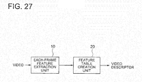
- FIG. 27 is a block diagram showing a video descriptor generation device described in this document.
- the article " TRECVID 2008 Content-Based Copy Detection By MCG-ICT-CAS" By Yongdong et al. discloses another example of video descriptor generation device.
- An each-frame feature extraction unit 10 calculates a frame unit feature from an input video, and outputs it to a feature table creation unit 20.
- the feature table creation unit 20 creates a feature table from the frame unit feature output from the each-frame feature extraction unit 10, and outputs the feature table as a video descriptor.
- the each-frame feature extraction unit 10 performs a process of extracting a feature such as the color of each frame from an input video, and outputs the obtained feature to the feature table creation unit 20 as a frame unit feature.
- the feature table creation unit 20 performs processing on variations in the feature between frames using a threshold, and compresses the feature in a time direction. Specifically, the feature table creation unit 20 calculates a difference between the frame unit features of frames, and determines whether or not the difference is within a certain allowable variation range. Then, the feature table creation unit 20 divides the video into time segments in which the video is within the allowable variation range, and for each of the divided time segments, a set of the feature and the time segment length (the number of frames) is output as a video descriptor.
- the feature of the video obtained for each frame can be compressed in a time direction, whereby the feature size can be reduced. Further, high-speed matching can also be realized.
- a first problem is that the retrieval accuracy is lowered when black bar regions or an L-shaped region is added around the video, because there is no means for performing feature extraction while detecting addition of the black bar regions or the L-shaped region.
- black bar regions black regions
- features are directly extracted without considering such a matter.
- the values of the features differ from the case of not including such regions, which deteriorates the retrieval accuracy.
- An object of the present invention is to provide a video descriptor generation device, a video descriptor generation method, and a video descriptor generation program, capable of maintaining retrieval accuracy even if black bar regions or an L-shaped region is added to a video.
- a video descriptor generation device includes a first extraction unit that extracts a first feature for each picture which is a frame or a field of a video; a second extraction unit that extracts a second feature from a region defined by an edge of an image included in the video; and a feature combining unit that combines the first feature and the second feature to generate a video descriptor.
- the present invention has an advantageous effect that retrieval accuracy can be maintained even if black bar regions or an L-shaped region is added to a video.
- the device includes a video edge detection unit 100, a visual feature extraction unit 120, a position-corrected visual feature extraction unit 130, and a feature combining unit 140.
- the video edge detection unit 100 calculates a video edge from a video, and outputs edge information to the position-corrected visual feature extraction unit 130.
- the visual feature extraction unit 120 receives the video, obtains a first feature from the video, and outputs it to the feature combining unit 140.
- the position-corrected visual feature extraction unit 130 obtains a second feature from the edge information output from the video edge detection unit 100 and the video, and outputs it to the feature combining unit 140.
- the feature combining unit 140 calculates a video descriptor from the first feature and the second feature, and outputs it.
- a video is input to the visual feature extraction unit 120. If the original video is encoded, the video is first decoded by a decoder, and then the data is input in picture units composed of frames or fields.
- the visual feature extraction unit 120 calculates a feature vector of each picture.
- the visual feature extraction unit 120 considers a picture as one still image, and extracts a vector of visual features indicating features such as colors, patterns, shapes, and the like of this picture.
- the calculated feature vector is output to the feature combining unit 140 as a first feature.
- the video is also input to the video edge detection unit 100.
- the video edge detection unit 100 detects whether or not there are black bar regions or an L-shaped region which are not originally included in the video, and if there is one, obtains the edge region thereof.
- black bar regions mean black extra regions inserted in top and bottom or right and left portions of the screen due to aspect conversion between 4:3 and 16:9. Although it is typically in black color, it is not necessarily black.
- an L-shaped (or inverse L-shaped) region is a video display technique used for broadcasting emergency news and the like, in which the actual video is slightly contracted to generate a space for broadcasting flash news. In that case, the color thereof is not black, usually. In either case, it is common that a region which is not in the original video is displayed. Examples of these regions are shown in Fig. 24 . In Fig. 24 , black regions correspond to black bar regions or L-shaped regions.
- this category also includes such cases as the case of a video presenting technique of incorporating another image into an image, which is so-called Picture in Picture, and the case of capturing by a camera a video shown on the back screen of a anchorperson, as a frame appears around the main video.
- a video presenting technique of incorporating another image into an image which is so-called Picture in Picture
- the case of capturing by a camera a video shown on the back screen of a anchorperson as a frame appears around the main video.
- the video edge detection unit 100 obtains such regions included in the picture, which have not been included in the original video, and the boundaries thereof. For example, it is possible to calculate the boundaries by applying Hough transform to the picture to detect linear components of the video, and obtaining linear components appearing at the same position within the picture in a temporarily continuous manner. Information describing the obtained video edges is output as edge information to the position-corrected visual feature extraction unit 130. As the edge information, it is possible to use a distance from an edge of the actual screen to the edge generated by a black bar region or an L-shaped region, for example. If bar regions only exist in top and bottom portions, the distance value to the boundaries of right and left should be set to 0. If an edge which is slightly tilted is also allowed, the angle thereof may be described together.
- the edge information is also possible to include symbols indicating the type of a black bar or an L-shaped region, such as an L shape, a horizontal black bar, and a vertical black bar, and parameters necessary for describing the bar regions of each pattern. For example, if the width of a portion where an L shape appears has been set to several types, the edge information should include a symbol representing the L-shape pattern and an index designating the width.
- the video is also input in picture units, along with the edge information.
- the position-corrected visual feature extraction unit 130 calculates features without regarding the region outside the position defined by the edge information. This means that features are extracted on the supposition that the region inside the position defined by the edge information is the entire image.
- the feature to be extracted is the same as that extracted by the visual feature extraction unit 120. For example, if the visual feature extraction unit 120 extracts a layout feature of color, the position-corrected visual feature extraction unit 130 also extracts a layout feature of color.
- the extracted feature is output as a second feature to the feature combining unit 140.
- the feature combining unit 140 combines the first feature output from the visual feature extraction unit 120 and the second feature output from the position-corrected visual feature extraction unit 130 to generate a video descriptor, and outputs it.
- both features may be simply combined to form one feature, or applied with particular encoding. It is also possible to encode the difference utilizing the fact that the first feature and the second feature have high correlation. This operation will be described below in detail.
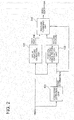
- the feature combining unit 140 includes an encoding unit 310, an encoding unit 320, and a code sequence multiplexing unit 230.
- the encoding unit 320 encodes an input first feature, and outputs a first feature code sequence obtained therefrom to the code sequence multiplexing unit 230.
- the encoding unit 310 encodes an input second feature and outputs a second feature code sequence obtained therefrom to the code sequence multiplexing unit 230.
- the code sequence multiplexing unit 230 multiplexes the first feature code sequence and the second feature code sequence to generate a video descriptor, and outputs it.
- a first feature is input to the encoding unit 320.
- the encoding unit 320 encodes the feature and generates a first feature code sequence.
- encoding means storing information in a predetermined format, including simply aligning the values of a feature vector according to the dimensions. For example, if an input vector is an integer vector in N dimensions, a format in which N pieces of integer values of the respective dimensions are aligned is acceptable. If an input vector has a float value, it is possible to perform quantization to express it as representative values of a limited number and align the indexes (quantization indexes) indicating the representative values. Further, it is also possible to perform entropy coding considering the appearance frequency of the respective values on the obtained integer values or representative values.
- entropy coding Huffman coding or arithmetic coding may be used. If there is correlation between dimensions of the feature vector, it is possible to perform entropy coding after performing a process of removing the correlation. For example, it is possible to obtain a difference of values between dimensions having correlation to perform difference encoding, or perform quantization or entropy coding after performing frequency conversion or the like on the input feature vector to generate a code sequence. Further, as a feature vector, if there is correlation between pictures, it is possible to calculate a difference from the feature vector of a past picture and encode it by means of the above encoding method to generate a code sequence. The generated first feature code sequence is output to the code sequence multiplexing unit 230.
- the second feature is input to the encoding unit 310.
- Operation of the encoding unit 310 is the same as that of the encoding unit 320.
- the encoding unit 310 encodes the second feature to generate a second feature code sequence.
- the generated second feature code sequence is output to the code sequence multiplexing unit 230.
- the code sequence multiplexing unit 230 multiplexes the first feature code sequence and the second feature code sequence to thereby generate a video descriptor.
- a video descriptor As shown in Fig. 25 , it is possible to simply integrating the first feature code sequence and the second feature code sequence with an identification code, which is used to specify a separable position, between them (however if the code sequences are in a fixed length or the length of the code sequence are described in somewhere, a code for identification is unnecessary), or constructing a video descriptor by alternately interleaving them in picture units.
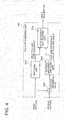
- the feature combining unit 140 includes a feature subtraction unit 300, an encoding unit 320, a feature difference encoding unit 340, and a code sequence multiplexing unit 330.
- the feature subtraction unit 300 subtracts the first feature from the second feature to calculate a difference between the features, and outputs a feature difference value to the feature difference encoding unit 340.
- the encoding unit 320 encodes the first feature, and outputs the obtained first feature code sequence to the code sequence multiplexing unit 330.
- the feature difference encoding unit 340 encodes the feature difference value output from the feature subtraction unit 300, and outputs the feature difference value code sequence to the code sequence multiplexing unit 330.
- the code sequence multiplexing unit 330 generates a video descriptor from the first feature code sequence output from the encoding unit 320 and the feature difference value code sequence output from the feature difference encoding unit 340, and outputs it.
- the first feature is input to the encoding unit 320. Operation of the encoding unit 320 is the same as that shown in Fig. 3 , and the first feature code sequence is output to the code sequence multiplexing unit 330. The first feature is also input to the feature subtraction unit 300. The second feature is also input to the feature subtraction unit 300.
- the first feature is subtracted from the second feature for each dimension of the feature vector, whereby a difference vector is calculated.
- the difference vector is output to the feature difference encoding unit 340 as a feature difference value.
- the feature difference encoding unit 340 encodes the feature difference value to generate a feature difference value code sequence.
- the first feature and the second feature are extracted from originally the same video with a difference in whether or not to include black bar regions or an L-shaped region, they have a large correlation. As such, it is considered that if differences between both features are calculated, distribution of the appeared values concentrates on the neighborhood of 0.
- a Huffman coding table based on the frequency distribution, and encode the difference values based on the table. If the feature difference values concentrate on almost 0, it is also possible to construct a code sequence as a combination of an index of a dimension having a value other than 0 and a code indicating the non-zero value.
- the generated feature difference value code sequence is output to the code sequence multiplexing unit 330.
- the code sequence multiplexing unit 330 integrates the first feature code sequence and the feature difference value code sequence to generate a video descriptor. Operation thereof is the same as that of the code sequence multiplexing unit 230 shown in Fig. 3 .
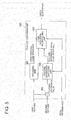
- the feature combining unit 140 includes a feature subtraction unit 300, an encoding unit 310, an encoding unit 320, a feature difference encoding unit 340, a code selection unit 520, and a code sequence multiplexing unit 530.
- the connection relation between the feature subtraction unit 300 and the encoding unit 320 is the same as that shown in Fig. 4 .
- the feature difference encoding unit 340 encodes a feature difference value output from the feature subtraction unit 300, and outputs a feature difference value code sequence to the code selection unit 520.
- the encoding unit 310 encodes a second feature, and outputs a second feature code sequence to the code selection unit 520.
- the code selection unit 520 selects one of the feature difference value code sequence output from the feature difference encoding unit 340 and the second feature code sequence output from the encoding unit 310, and outputs it to the code sequence multiplexing unit 530 as a third feature code sequence.
- the code sequence multiplexing unit 530 generates a video descriptor from the first feature code sequence output from the encoding unit 320 and the third feature code sequence output from the code selection unit 520, and outputs it.
- Operation of the encoding unit 310 and the encoding unit 320 is the same as that shown in Fig. 3 . Further, operation of the feature subtraction unit 300 and the feature difference encoding unit 340 is the same as that shown in Fig. 4 .
- the feature difference value code sequence output from the feature difference encoding unit 340 and the second feature code sequence output from the encoding unit 310 are input to the code selection unit 520.
- the code selection unit 520 compares the quantities of codes between the feature difference value code sequence and the second feature code sequence in each picture or in a unit of a plurality of pictures, selects a code sequence having smaller quantity of generated codes, and outputs it to the code sequence multiplexing unit 530 as a third feature code sequence.
- information indicating which way is used for coding is output, as mode information, to the code sequence multiplexing unit 530 in a picture unit or a unit of a plurality of pictures.
- the code sequence multiplexing unit 530 integrates the first feature code sequence and the third feature code sequence to generate a video descriptor. Although the operation thereof is almost similar to that of the code sequence multiplexing unit 230 shown in Fig. 3 , the point that mode information is also included in the video descriptor is the difference.
- the feature combining unit 140 shown in Fig. 6 has a means for directly encoding the second feature, it is possible to prevent an increase in the feature size even in the case where the features largely differ depending on black bar regions or an L-shaped region so that encoding a feature difference value is inappropriate from a viewpoint of encoding efficiency.
- the first embodiment of the video descriptor generation device has been described above. With the first embodiment, it is possible to extract a video descriptor capable of preventing deterioration in retrieval accuracy even in the case of including black bar regions or an L-shaped region. This is because the first embodiment detects black bar regions or an L-shaped region, and has information of the features extracted from the regions excluding the detected regions. As such, in the case of a moving image including black bar regions or an L-shaped region, retrieval accuracy can be maintained by comparing the features of the regions excluding those regions. Further, the first embodiment also has the features with respect to the entire video in which those regions are not removed. As such, even if there are any errors in detecting black bar regions or an L-shaped region, it is possible to perform matching between the features of entire images, whereby deterioration of the accuracy can be prevented.
- the device includes a video edge detection unit 100, a visual feature extraction unit 120, a position-corrected visual feature extraction unit 130, and a feature combining unit 240.
- a feature combining unit 240 is used instead of the feature combining unit 140 and edge information output from the video edge detection unit 100 is also input to the feature combining unit 240 differs from the case of Fig. 1 .
- Operation of the video edge detection unit 100, the visual feature extraction unit 120, and the position-corrected visual feature extraction unit 130 is the same as that of the video descriptor generation device shown in Fig. 1 .
- a first feature output from the visual feature extraction unit 120 and a second feature output from the position-corrected visual feature extraction unit 130 are input to the feature combining unit 240. Further, edge information output from the video edge detection unit 100 is also input to the feature combining unit 240.
- the operation of the feature combining unit 240 is also similar basically to that of the feature combining unit 140 shown in Fig. 1 , an aspect of generating a video descriptor by controlling an encoding method by edge information and an aspect of including the edge information or its related information in the video descriptor differ from the case shown in Fig. 1 .
- the details of these aspects will be described below.
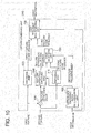
- the feature combining unit 240 includes a feature subtraction unit 300, an encoding unit 320, a feature difference encoding unit 440, and a code sequence multiplexing unit 430.
- the connection relation between the feature subtraction unit 300 and the encoding unit 320 is the same as that shown in Fig. 4 .
- the feature difference encoding unit 440 encodes a feature difference value from the feature difference value output from the feature subtraction unit 300 and edge information, and outputs a feature difference value code sequence to the code sequence multiplexing unit 430.
- the code sequence multiplexing unit 430 generates a video descriptor from the first feature code sequence output from the encoding unit 320, the feature difference value code sequence output from the feature difference encoding unit 440, and the edge information, and outputs it.
- the feature difference encoding unit 440 encodes the feature difference value output from the feature subtraction unit 300 to generate a feature difference value code sequence. This operation is basically similar to the operation of the feature difference encoding unit 340 described in Fig. 4 . However, the case of the feature difference encoding unit 440 differs from the case of the feature difference encoding unit 340 in that an encoding parameter is controlled by edge information indicating black bar regions or an L-shaped region. As such, an encoding parameter is changed according to edge information. Distribution of difference values in the respective dimensions of a feature vector is changed depending on the size of black bar regions or an L-shaped region, appearance location thereof, and the like.
- entropy coding is performed by selecting distribution of difference values to be used according to the edge information to perform arithmetic coding according to the distribution, or selecting a Huffman table to be used according to the edge information to perform Huffman coding.
- the generated feature difference value code sequence is output to the code sequence multiplexing unit 430.
- the code sequence multiplexing unit 430 generates a video descriptor by multiplexing a first feature code sequence output from the encoding unit 320, a feature difference value code sequence output from the feature difference encoding unit 440, and the edge information. While this operation is basically similar to that of the code sequence multiplexing unit 330 shown in Fig. 4 , an aspect of multiplexing the edge information together differs. It should be noted that the edge information may be one obtained by encoding the information or indexing the information, rather than the information itself.
- the feature difference encoding unit 440 if encoding parameters to be used in a Huffman table or arithmetic coding are classified into some classes and one of them is selected, it is possible to multiplex an index identifying this class, or allocate a code which can specify this index.
- the feature combining unit 240 includes a feature subtraction unit 300, an encoding unit 320, a difference encoding index determination unit 600, an encoding unit 610, a feature difference encoding unit 640, and a code sequence multiplexing unit 630.
- the connection relation between the feature subtraction unit 300 and the encoding unit 320 is the same as that shown in Fig. 4 .
- the difference encoding index determination unit 600 receives edge information, and outputs difference encoding indexes to the feature difference encoding unit 640 and the encoding unit 610.
- the feature difference encoding unit 640 encodes a feature difference value output from the feature subtraction unit 300 based on the difference encoding indexes output from the difference encoding index determination unit 600, and outputs a feature difference value code sequence to the code sequence multiplexing unit 630.
- the encoding unit 610 encodes the second feature based on the difference encoding indexes output from the difference encoding index determination unit 600, and outputs a second feature code sequence to the code sequence multiplexing unit 630.
- the code sequence multiplexing unit 630 multiplexes the first feature code sequence output from the encoding unit 320, the feature difference value code sequence output from the feature difference encoding unit 640, the second feature code sequence output from the encoding unit 610, and the edge information to generate a video descriptor, and outputs it.
- the difference encoding index determination unit 600 determines dimensions for performing difference encoding, among the respective dimensions of the features, based on the input edge information, and outputs indexes indicating the dimensions as difference encoding indexes.
- the difference encoding indexes are output to the feature difference encoding unit 640 and the encoding unit 610.
- the feature difference encoding unit 640 encodes feature difference values with respect to the dimensions corresponding to the input difference encoding indexes to generate a feature difference value code sequence.
- the method of encoding the feature difference value is the same as the feature difference encoding unit 340 shown in Fig. 4 .
- the generated feature difference value code sequence is output to the code sequence multiplexing unit 630.
- the encoding unit 610 encodes a second feature of dimensions not corresponding to the input difference encoding indexes to generate a second feature code sequence.
- the method of encoding the second feature is the same as that used by the encoding unit 310 shown in Fig. 3 .
- the generated second feature code sequence is output to the code sequence multiplexing unit 630.
- the code sequence multiplexing unit 630 multiplexes the first feature code sequence output from the encoding unit 320, the feature difference value code sequence output from the feature difference encoding unit 640, the second feature code sequence output from the encoding unit 610, and the edge information to thereby generate a video descriptor.
- the video descriptor may be generated by simply integrating those code sequences, or alternately interleaving them in picture units. Multiplexing of the edge information is the same as that performed by the code sequence multiplexing unit 430 shown in Fig. 5 .
- the feature combining unit 240 includes a feature subtraction unit 300, an encoding unit 320, a difference encoding index determination unit 600, an encoding unit 610, a feature difference encoding unit 640, and a code sequence multiplexing unit 830.
- the configuration of the feature combining unit 240 is similar to the configuration shown in Fig. 7 except that a code sequence multiplexing unit 830 is used instead of the code sequence multiplexing unit 630, and that a difference encoding index is input to the code sequence multiplexing unit 830 instead of edge information.
- Operation of the unit other than the code sequence multiplexing unit 830 is the same as that shown in Fig. 7 .
- the operation of the code sequence multiplexing unit 830 is also similar to that of the code sequence multiplexing unit 630 shown in Fig. 7 except for an aspect of multiplexing difference encoding indexes instead of edge information.
- the feature combining unit 240 shown in Fig. 8 provides another embodiment having the same advantageous effect as that of Fig. 7 .
- the feature combining unit 240 includes a feature subtraction unit 300, an encoding unit 320, a difference encoding index determination unit 600, an encoding unit 610, a feature difference encoding unit 660, and a code sequence multiplexing unit 630.
- the configuration thereof is similar to that shown in Fig. 7 except that the feature difference encoding unit 660 is used instead of the feature difference encoding unit 640, and that the feature difference encoding unit 660 also receives edge information.
- Operation other than that of the feature difference encoding unit 660 is the same as the case shown in Fig. 7 .
- Operation of the feature difference encoding unit 660 is also similar to that of the feature difference encoding unit 640 shown in Fig. 7 except that encoding is performed by changing an encoding parameter according to edge information.
- a method of performing encoding by changing an encoding parameter according to edge information is the same as the case of the feature difference encoding unit 440 shown in Fig. 5 .
- the feature combining unit 240 includes a feature subtraction unit 300, an encoding unit 320, a difference encoding index determination unit 600, an encoding unit 310, a feature difference encoding unit 640, a code selection unit 720, and a code sequence multiplexing unit 730.
- the connection relation between the feature subtraction unit 300, the encoding unit 320, and the difference encoding index determination unit 600 is the same as that shown in Fig. 7 .
- the feature difference encoding unit 640 applies difference-encoding to a feature difference value output from the feature subtraction unit 300 based on the difference encoding index output from the difference encoding index determination unit 600, and outputs a feature difference value code sequence to the code selection unit 720.
- the encoding unit 310 encodes a second feature and outputs a second feature code sequence to the code selection unit 720.
- the code selection unit 720 selects a code sequence based on the difference encoding index output from the difference encoding index determination unit 600, and outputs the selected code sequence as a third feature code sequence to the code sequence multiplexing unit 730.
- the code sequence multiplexing unit 730 generates a video descriptor from the first feature code sequence output from the encoding unit 320, the third feature code sequence output from the code selection unit 720, and the edge information, and outputs it.
- Operation of the feature subtraction unit 300, the encoding unit 320, the difference encoding index determination unit 600, and the feature difference encoding unit 640 is the same as the case shown in Fig. 7 . Further, operation of the encoding unit 310 is the same as the case shown in Fig. 6 .
- the code selection unit 720 calculates, with respect to each of the feature difference value code sequence output from the feature difference encoding unit 640 and the second feature code sequence output from the encoding unit 310, the total sum of code quantities of the dimension corresponding to the difference encoding indexes output from the difference encoding index determination unit 600. For the dimension corresponding to the difference encoding index, a code sequence with which the total sum of the code quantities becomes small is selected. On the other hand, for a dimensions not corresponding to the difference encoding index, the codes of the second feature code sequence are selected. This is determined at predetermined intervals. As the interval, it is possible to use a picture or a segment configured of a plurality of pictures may be used.
- the code selection unit 720 outputs the selected code sequence to the code sequence multiplexing unit 730 as a third feature code sequence.
- information indicating which of the ways is used for encoding is output as mode information to the code sequence multiplexing unit 730 for each picture or for each unit of pictures.
- the code sequence multiplexing unit 730 multiplexes the first feature code sequence output from the encoding unit 320, the third feature code sequence output from the code selection unit 720, the edge information, and the mode information to thereby generate a video descriptor.
- the multiplexing method is almost similar to that of the case of the code sequence multiplexing unit 430 shown in Fig. 5 , except that the mode information is also included in the video descriptor.
- the feature combining unit 240 includes a feature subtraction unit 300, an encoding unit 320, a difference encoding index determination unit 600, an encoding unit 310, a feature difference encoding unit 640, a code selection unit 720, and a code sequence multiplexing unit 930.
- the configuration thereof is similar to the case of Fig. 10 , except that the code sequence multiplexing unit 930 is used instead of the code sequence multiplexing unit 730, and that a difference encoding index is input, instead of the difference encoding index, to the code sequence multiplexing unit 930.
- Operation other than that of the code sequence multiplexing unit 930 is the same as the case of Fig. 10 .
- Operation of the code sequence multiplexing unit 930 is also similar to that of the code sequence multiplexing unit 730 shown in Fig. 10 except for an aspect of multiplexing difference encoding indexes instead of edge information.
- the feature combining unit shown in Fig. 11 provides another embodiment having the same effect as that of Fig. 10 .
- the feature combining unit 240 includes a feature subtraction unit 300, an encoding unit 320, a difference encoding index determination unit 600, an encoding unit 310, a feature difference encoding unit 660, a code selection unit 720, and a code sequence multiplexing unit 730.
- the configuration thereof is similar to that of the case shown in Fig. 10 except that the feature difference encoding unit 660 is used instead of the feature difference encoding unit 640 and that edge information is also input to the feature difference encoding unit 660.
- Operation other than that of the feature difference encoding unit 660 is the same as the case shown in Fig. 10 .
- Operation of the feature difference encoding unit 660 is also similar to the feature difference encoding unit 640 shown in Fig. 10 except for an aspect of performing encoding by changing an encoding parameter according to edge information.
- the method of performing encoding by changing an encoding parameter according to edge information is the same as the case of the feature difference encoding unit 440 shown in Fig. 5 .
- the second embodiment of the video descriptor generation device has been described above. With the second embodiment, it is possible to optimize the method of encoding features according to the size of black bars or an L-shaped region, whereby the encoding effectiveness of a video descriptor can be improved.
- the moving image matching device includes feature reproduction units 1000 and 1010, feature matching units 1020, 1030, 1040, and 1050, and a selection unit 1060.
- the feature reproduction unit 1000 receives a first video descriptor, outputs a separated first feature of a first video to the feature matching units 1020 and 1030, and outputs a separated second feature of the first video to the feature matching units 1040 and 1050.
- the feature reproduction unit 1010 receives a second video descriptor, outputs a separated first feature of a second video to the feature matching units 1020 and 1040, and outputs a separated second feature of the second video to the feature matching units 1030 and 1050.
- the feature matching unit 1020 receives the first feature of the first video and the first feature of the second video, and outputs a first matching score to the selection unit 1060.
- the feature matching unit 1030 receives the first feature of the first video and the second feature of the second video, and outputs a second matching score to the selection unit 1060.
- the feature matching unit 1040 receives the second feature of the first video and the first feature of the second video, and outputs a third matching score to the selection unit 1060.
- the feature matching unit 1050 receives the second feature of the first video and the second feature of the second video, and outputs a fourth matching score to the selection unit 1060.
- the selection unit 1060 compares the first to fourth matching scores, selects one of them, and outputs it as a matching score.
- a first video descriptor is input to the feature reproduction unit 1000.
- the feature reproduction unit 1000 reproduces the feature from the first video descriptor, extracts a first feature of a first video which is a feature of the case of not eliminating black bar regions and a second feature of the first video which is a feature of the case of eliminating the black bar regions, and outputs them.
- a second video descriptor is input to the feature reproduction unit 1010.
- the feature reproduction unit 1010 similarly extracts a first feature of the second video which is a feature of the case of not eliminating black bar regions and a second feature of the second video which is a feature of the case of eliminating the black bar regions, and outputs them.
- the first feature of the first video and the first feature of the second video are input.
- matching is performed on the features of the first video and the second video of the case of not eliminating the black bar regions.
- the values of the features are compared for each picture, and a scale representing a distance between the features or a similarity between the features is calculated.
- This process is performed on a plurality of continuous pictures to perform statistical processing, whereby a distance or a similarity (regarding the similarity, it is determined to be more similar as the value is larger) between the videos constituted of those pictures is calculated.
- the statistical processing includes calculating a total amount or an average of the values of each picture, calculating a maximum value, and calculating a median value.
- the calculated matching score is output to the selection unit 1060.
- Operation of the feature matching unit 1030, the feature matching unit 1040, and the feature matching unit 1050 is also similar to that of the feature matching unit 1020, basically.
- the feature matching unit 1030 compares the first feature of the first video and the second feature of the second video
- the feature matching unit 1030 calculates a matching score of the case of not eliminating the black bars in the first video and the case of eliminating the black bars in the second video.
- the feature matching unit 1040 compares the second feature of the first video and the first feature of the second video
- the feature matching unit 1040 calculates a matching score of the case of eliminating the black bars in the first video and the case of not eliminating the black bars in the second video.
- the feature matching unit 1050 compares the second feature of the first video and the second feature of the second video
- the feature matching unit 1050 calculates a matching score between the cases of eliminating the black bars in the first video and the second video.
- the matching scores are calculated while shifting the pictures in a time direction. It should be noted that the matching is performed on all combinations in which black bars are eliminated and not eliminated, in order to prevent deterioration in matching accuracy when black bars are erroneously detected in the black bar elimination processing. In this way, the matching scores calculated by the feature matching units 1030, 1040, 1050, and 1060 are output to the selection unit 1060.
- the selection unit 1060 selects a score indicating the highest matching degree among the input matching scores. This means that if the matching score is defined by a distance, the selection unit 1060 selects a smallest value, while if the matching score is defined by a similarity, the selection unit 1060 selects a largest value.
- the feature reproduction unit 1000 includes a code sequence demultiplexing unit 1100, a decoding unit 1110, and a decoding unit 1120.
- the code sequence demultiplexing unit 1100 receives a video descriptor, outputs a separated first feature code sequence to the decoding unit 1110, and also outputs a second feature code sequence to the decoding unit 1120.
- the decoding unit 1110 decodes the first feature code sequence output from the code sequence demultiplexing unit 1100, generates a first feature, and outputs it.
- the decoding unit 1120 decodes the second feature code sequence output from the code sequence demultiplexing unit 1100, generates a second feature, and outputs it.
- a video descriptor on which matching is performed is first input to the code sequence demultiplexing unit 1100.
- the code sequence demultiplexing unit 1100 separates the first feature code sequence and the second feature code sequence from the video descriptor by means of a demultiplexing method corresponding to the method used for multiplexing. For example, in the multiplexing, if the first feature code sequence and the second feature code sequence are simply integrated with a separable identification code between them, the code sequence demultiplexing unit 1100 identifies the identification code and separates them such that the part before the code is a first feature code sequence and the part after the code is a second feature code sequence.
- the code sequence demultiplexing unit 1100 separates them in picture units and reconstructs a code sequence. At that time, if they are constructed to be separable with an identification code between them, the code sequence demultiplexing unit 1100 separates them by identifying the identification code, while if the length of the code sequence for each of the pictures is included as header information, the code sequence demultiplexing unit 1100 separates them by delimiting them by the length.
- the first feature code sequence and the second feature code sequence separated in this manner are respectively output to the decoding unit 1110 and the decoding unit 1120.
- the decoding unit 1110 decodes the first feature code sequence to generate a first feature.
- the decoding method depends on the method used for encoding. For example, if an input vector is an integer vector in N dimensions and a code sequence is generated in a format of simply aligning N pieces of integer values of the respective dimensions, it is only necessary to simply acquire the N-dimensional vector. In the case where an input vector is quantized and representative values (quantization indexes) are aligned, it is possible to perform inverse quantization after acquiring the representative values (or representative values obtained from the quantization indexes). In the case where entropy coding is performed, decoding corresponding thereto should be performed to obtain the symbol.
- Huffman coding is performed as entropy coding, it is possible to perform decoding using the Huffman table used for the encoding. If arithmetic encoding is performed, it is possible to perform arithmetic decoding using frequency distribution of the symbol used for the encoding. If entropy coding is performed after performing a process of removing correlation between dimensions, features can be calculated by first performing entropy decoding and then performing decoding corresponding to the processing performed for removing the correlation. If quantization and entropy coding are performed by performing frequency conversion, it is possible to calculate features by performing inverse quantization and inverse conversion of the frequency conversion after entropy decoding. If encoding is performed by calculating a difference from a feature of a past picture, it is possible to calculate a current feature of the picture by adding the value obtained by decoding to the feature of the past picture.
- the decoding unit 1120 decodes the second feature code sequence and generates a second feature. Operation of the decoding unit 1120 is the same as that of the decoding unit 1110.
- the feature reproduction unit 1000 shown in Fig. 14 provides a means for separating the features combined by the feature combining unit 140 shown in Fig. 3 .
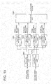
- the feature reproduction unit 1000 includes a code sequence demultiplexing unit 1200, a decoding unit 1110, a feature difference decoding unit 1230, and a feature addition unit 1240.
- the code sequence demultiplexing unit 1200 receives a video descriptor, outputs a separated first feature code sequence to the decoding unit 1110, and outputs a feature difference value code sequence to the feature difference decoding unit 1230.
- the decoding unit 1110 decodes a first feature code sequence output from the code sequence demultiplexing unit 1200, and outputs a first feature.
- the feature difference decoding unit 1230 decodes the feature difference value code sequence output from the code sequence demultiplexing unit 1200, and outputs the obtained feature difference value to the feature addition unit 1240.
- the feature addition unit 1240 adds the first feature output from the decoding unit 1110 and the feature difference value output from the feature difference decoding unit 1230 to calculate a second feature, and outputs it.
- a video descriptor on which matching is performed is first input to the code sequence demultiplexing unit 1200.
- the code sequence demultiplexing unit 1200 separates the first feature code sequence and the feature difference value code sequence from the video descriptor by means of a demultiplexing method corresponding to the method used for multiplexing. This operation is the same as that performed by the code sequence demultiplexing unit 1100 of the feature reproduction unit shown in Fig. 14 .
- the separated first feature code sequence and the feature difference value code sequence are respectively output to the decoding unit 1110 and the feature difference decoding unit 1230.
- the decoding unit 1110 outputs a first feature.
- the first feature is also output to the feature addition unit 1240.
- the feature difference decoding unit 1230 decodes the feature difference value code sequence to obtain a feature difference value.
- decoding is performed by performing inverse processing to the processing performed for encoding. For example, if encoding is performed by Huffman coding or arithmetic coding, decoding is performed by a corresponding decoding process.
- the obtained feature difference value is output to the feature addition unit 1240.
- the feature addition unit 1240 adds the first feature output from the decoding unit 1110 and the feature difference value output from the feature difference decoding unit 1230 to reproduce the second feature, and outputs the obtained second feature.
- the feature reproduction unit 1000 shown in Fig. 15 provides a means for separating the features combined by the feature combining unit 140 shown in Fig. 14 .
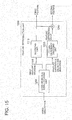
- the feature reproduction unit 1000 includes a code sequence demultiplexing unit 1300, a decoding unit 1110, a feature difference decoding unit 1330, and a feature addition unit 1240.
- the code sequence demultiplexing unit 1300 receives a video descriptor, outputs a separated first feature code sequence to the decoding unit 1110, and also outputs a feature difference value code sequence and edge information to the feature difference decoding unit 1330.
- the connection relation between the decoding unit 1110 and the feature addition unit 1240 is the same as that shown in Fig. 15 .
- the feature difference decoding unit 1330 decodes the feature difference value code sequence output from the code sequence demultiplexing unit 1300 based on the edge information output from the code sequence demultiplexing unit 1300, and outputs a feature difference value to the feature addition unit 1240.
- the decoding unit 1110 decodes the first feature code sequence output from the code sequence demultiplexing unit 1300, and outputs a first feature.
- the feature addition unit 1240 adds the first feature output from the decoding unit 1110 and the feature difference value output from the feature difference decoding unit 1330 to calculate a second feature, and outputs it.
- a video descriptor on which matching is performed is first input to the code sequence demultiplexing unit 1300. While operation of the code sequence demultiplexing unit 1300 is similar to that of the code sequence demultiplexing unit 1200 shown in Fig. 15 , it also outputs edge information. The edge information is output to the feature difference decoding unit 1330.
- While operation of the feature difference decoding unit 1330 is basically similar to that of the feature difference decoding unit 1230 shown in Fig. 15 , it differs in that a coding parameter is specified using the input edge information and decoding is performed using the parameter.
- the feature reproduction unit 1000 shown in Fig. 16 provides a means for separating the features combined by the feature combining unit 240 shown in Fig. 5 .
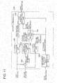
- the feature reproduction unit 1000 includes a code sequence demultiplexing unit 1400, a decoding unit 1110, a decoding unit 1410, a feature difference decoding unit 1430, a feature addition unit 1240, a switching unit 1440, and a switching unit 1450.
- the code sequence demultiplexing unit 1400 receives a video descriptor, outputs a separated first feature code sequence to the decoding unit 1110, and outputs a third feature code sequence to the switching unit 1440. Further, the code sequence demultiplexing unit 1400 also outputs mode information for controlling switching units to the switching unit 1440 and the switching unit 1450.
- the decoding unit 1110 receives the first feature code sequence output from the code sequence demultiplexing unit 1400, and outputs a first feature.
- the switching unit 1440 outputs the third feature code sequence output from the code sequence demultiplexing unit 1400 to either the feature difference decoding unit 1430 or the decoding unit 1410 according to the mode information input from the code sequence demultiplexing unit 1400.
- the feature difference decoding unit 1430 receives the third feature code sequence output from the switching unit 1440, and outputs a feature difference value to the feature addition unit 1240.
- the decoding unit 1410 receives the third feature code sequence output from the switching unit 1440, and outputs a decoding result to the switching unit 1450.
- the feature addition unit 1240 receives the first feature output from the decoding unit 1110 and the feature difference value output from the feature difference decoding unit 1430, and outputs the addition result to the switching unit 1450.
- the switching unit 1450 receives the addition result output from the feature addition unit 1240 and the decoding result output from the decoding unit 1410, reconstructs the second feature based on the mode information output from the code sequence demultiplexing unit 1400, and outputs it.
- a video descriptor on which matching is performed is first input to the code sequence demultiplexing unit 1400.
- the code sequence demultiplexing unit 1400 separates the first feature code sequence and the third feature code sequence from the video descriptor by means of a demultiplexing method corresponding to the method used for multiplexing. This operation is the same as that performed by the code sequence demultiplexing unit 1100 of the feature reproduction unit shown in Fig. 14 .
- the separated first feature code sequence and the third feature code sequence are respectively output to the decoding unit 1110 and the switching unit 1440.
- the mode information is also demultiplexed from the video descriptor, and output to the switching unit 1440 and the switching unit 1450.
- the decoding unit 1110 outputs a first feature.
- the first feature is also output to the feature addition unit 1240.
- the switching unit 1440 changes the output destination of the third feature code sequence according to the mode information output from the code sequence demultiplexing unit 1400. If the mode information indicates that the feature included in the third feature code sequence is a feature difference value, the switching unit 1440 outputs the third feature code sequence to the feature difference decoding unit 1430. On the other hand, if the mode information indicates that the feature included in the third feature code sequence is a second feature, the switching unit 1440 outputs the third feature code sequence to the decoding unit 1410.
- the timing of switching the output destination according to the mode information depends on how the third feature code sequence is created at the time of encoding. If the entire video is encoded in one mode, it is possible to set the output destination once at the beginning according to the mode information.
- the video is encoded such that the mode is switched in picture units, it is possible to perform switching in picture units. If the video is encoded such that the mode is switched for each unit of a plurality of pictures or switched in region units within the picture, it is possible to perform switching according to the units.
- the feature difference decoding unit 1430 decodes the third feature code sequence output from the switching unit 1440 to thereby reproduce (a part of) the feature difference value. Operation of the feature difference decoding unit 1430 is basically similar to that of the feature difference decoding unit 1230 shown in Fig. 15 . However, if a part of the feature difference value code sequence (e.g., only part of the pictures) is to be decoded by the feature difference decoding unit 1430 depending on the mode, information specifying that features corresponding to which pictures or which regions are to be decoded is also included in the third feature code sequence. As such, the feature difference decoding unit 1430 performs decoding while referring to such information. The obtained feature difference value is output to the feature addition unit 1240.
- Operation of the feature addition unit 1240 is the same as the case shown in Fig. 15 , and an addition result which is a (part of) second feature is output to the switching unit 1450.
- the decoding unit 1410 decodes the third feature code sequence output from the switching unit 1440 to thereby reproduce (a part of) the second feature. Operation of the decoding unit 1410 is basically similar to that of the decoding unit 1120 shown in Fig.14 . However, if a part of the third feature code sequence (e.g., only part of the pictures) is to be decoded by the decoding unit 1410 depending on the mode, information specifying that features corresponding to which pictures or which regions are to be decoded is also included in the third feature code sequence. As such, the decoding unit 1410 performs decoding while referring to this information. The decoding result is output to the switching unit 1450.
- the switching unit 1450 switches the output source of the second feature according to the mode information output from the code sequence demultiplexing unit 1400. If the mode information indicates that the feature included in the third feature code sequence is a feature difference value, the switching unit 1450 outputs the addition result output from the feature addition unit 1240 as a second feature. On the other hand, if the mode information indicates that the feature included in the third feature code sequence is a second feature, the switching unit 1450 outputs the decoding result output from the decoding unit 1410 as a second feature.
- the feature reproduction unit shown in Fig. 17 provides a means for separating the features combined by the feature combining unit 140 shown in Fig. 6 .
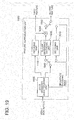
- the feature reproduction unit 1000 includes a code sequence demultiplexing unit 1500, a decoding unit 1110, a decoding unit 1510, a feature difference decoding unit 1530, a feature addition unit 1240, a switching unit 1540, a switching unit 1550, and a difference encoding index determination unit 1560.
- the code sequence demultiplexing unit 1500 receives a video descriptor, outputs a separated first feature code sequence to the decoding unit 1110, and outputs a third feature code sequence to the switching unit 1540.
- the code sequence demultiplexing unit 1500 also outputs edge information to the difference encoding index determination unit 1560.
- the difference encoding index determination unit 1560 receives the edge information output from the code sequence demultiplexing unit 1500, and outputs difference encoding indexes to the switching unit 1540 and the switching unit 1550.
- the decoding unit 1110 receives the first feature code sequence output from the code sequence demultiplexing unit 1500, and outputs a first feature.
- the switching unit 1540 outputs the third feature code sequence output from the code sequence demultiplexing unit 1500 to either the feature difference decoding unit 1530 or the decoding unit 1510, according to the difference encoding indexes input from the difference encoding index determination unit 1560.
- the decoding unit 1510 receives the third feature code sequence output from the switching unit 1540, and outputs the decoding result to the switching unit 1550.
- the feature difference decoding unit 1530 receives the third feature code sequence output from the switching unit 1540, and outputs a feature difference value to the feature addition unit 1240.
- the feature addition unit 1240 adds the first feature output from the decoding unit 1110 and the feature difference value output from the feature difference decoding unit 1530, and outputs the addition result to the switching unit 1550.
- the switching unit 1550 receives the addition result output from the feature addition unit 1240 and the decoding result output from the decoding unit 1510, reconstructs a second feature based on the difference encoding indexes output from the difference encoding index determination unit 1560, and outputs it.
- a video descriptor on which matching is performed is first input to the code sequence demultiplexing unit 1500.
- the code sequence demultiplexing unit 1500 separates the first feature code sequence and the third feature code sequence from the video descriptor by means of a demultiplexing method corresponding to the method used for multiplexing. This operation is the same as that performed by the code sequence demultiplexing unit 1100 of the feature reproduction unit shown in Fig. 14 .
- the separated first feature code sequence and the third feature code sequence are respectively output to the decoding unit 1110 and the switching unit 1540.
- the edge information which is information describing the edge in the screen formed by black regions or an L-shaped region, is also demultiplexed from the video descriptor, and output to the difference encoding index determination unit 1560.
- the difference encoding index determination unit 1560 is the same as that used for encoding.
- the difference encoding index determination unit 1560 determines dimensions, among the respective dimensions of the feature, on which difference encoding is performed, and outputs indexes representing the dimension as difference encoding indexes.
- the decoding unit 1110 outputs a first feature.
- the first feature is also output to the feature addition unit 1240.
- the switching unit 1540 changes the output destination of the third feature code sequence for each dimension of the feature, according to the difference encoding indexes output from the difference encoding index determination unit 1560. With respect to the dimensions designated by the difference encoding indexes, the switching unit 1540 outputs the third feature code sequence to the feature difference decoding unit 1530. On the other hand, with respect to the dimensions not designated by the difference encoding indexes, the switching unit 1540 outputs the third feature code sequence to the decoding unit 1510.
- the feature difference decoding unit 1530 decodes the third feature code sequence output from the switching unit 1540, and reproduces the value, among the feature difference values, of the dimension designated by the difference encoding indexes. Operation of the feature difference decoding unit 1530 is basically similar to that of the feature difference decoding unit 1230 shown in Fig. 15 . The obtained feature difference value is output to the feature addition unit 1240.
- the decoding unit 1510 decodes the third feature code sequence output from the switching unit 1540, and reproduces the value of the dimensions not designated by the difference encoding indexes, of the second feature. Operation of the decoding unit 1510 is basically similar to that of the decoding unit 1120 shown in Fig. 14 . The decoding result is output to the switching unit 1550.
- the switching unit 1550 switches the output destination of the second feature according to the difference encoding indexes output from the difference encoding index determination unit 1560. With respect to the dimensions included in the difference encoding indexes, the switching unit 1550 outputs the addition result output from the feature addition unit 1240 as a second feature. On the other hand, with respect to the dimensions not included in the difference encoding indexes, the switching unit 1550 outputs the decoding result output from the decoding unit 1510 as a second feature.
- the feature reproduction unit 1000 shown in Fig. 18 provides a means for separating the features combined by the feature combining unit 240 shown in Fig. 7 .
- the feature reproduction unit 1000 includes a code sequence demultiplexing unit 1600, a decoding unit 1110, a decoding unit 1510, a feature difference decoding unit 1530, a feature addition unit 1240, a switching unit 1540, and a switching unit 1550.
- the configuration thereof is similar to that shown in Fig. 18 except for the code sequence demultiplexing unit 1600, the switching unit 1540, and the switching unit 1550.
- the code sequence demultiplexing unit 1600 receives a video descriptor, outputs a separated first feature code sequence to the decoding unit 1110, and also outputs a third feature code sequence to the switching unit 1540. Further, the code sequence demultiplexing unit 1600 outputs difference encoding indexes to the switching unit 1540 and the switching unit 1550.
- the switching unit 1540 outputs the third feature code sequence output from the code sequence demultiplexing unit 1500 to either the feature difference decoding unit 1530 or the decoding unit 1510, according to the difference encoding indexes output from the code sequence demultiplexing unit 1600.
- the switching unit 1550 receives the addition result output from the feature addition unit 1240 and the decoding result output from the decoding unit 1510, reconstructs the second feature based on the difference encoding indexes output from the code sequence demultiplexing unit 1600, and outputs it.
- Operation other than that of the code sequence demultiplexing unit 1600 is the same as the case of Fig. 18 .
- Operation of the code sequence demultiplexing unit 1600 is also similar to that of the code sequence demultiplexing unit 1500 shown in Fig. 18 except for an aspect of demultiplexing a difference encoding indexes instead of edge information.
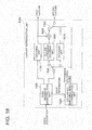
- the feature reproduction unit 1000 shown in Fig. 19 provides a means for separating the features combined by the feature combining unit 240 shown in Fig. 8 .
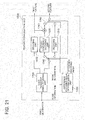
- the feature reproduction unit 1000 includes a code sequence demultiplexing unit 1500, a decoding unit 1110, a decoding unit 1510, a feature difference decoding unit 1730, a feature addition unit 1240, a switching unit 1540, and a switching unit 1550.
- the connection relation between the units other than the code sequence demultiplexing unit 1500 and the feature difference decoding unit 1730 is the same as that shown in Fig. 18 .
- the code sequence demultiplexing unit 1500 receives a video descriptor, outputs a separated first feature code sequence to the decoding unit 1110, and outputs a third feature code sequence to the switching unit 1540. Further, the code sequence demultiplexing unit 1500 outputs edge information to the difference encoding index determination unit 1560 and the feature difference decoding unit 1730.
- the feature difference decoding unit 1730 receives the third feature code sequence output from the switching unit 1540 and the edge information output from the code sequence demultiplexing unit 1500, and outputs a feature difference value to the feature addition unit 1240.
- Operation other than that of the feature difference decoding unit 1730 is the same as the case shown in Fig. 18 .
- Operation of the feature difference decoding unit 1730 is also similar to that of the feature difference decoding unit 1530 shown in Fig. 18 , except for an aspect of performing decoding by changing the coding parameter according to the edge information.
- the feature reproduction unit 1000 shown in Fig, 20 provides a means for separating the features combined by the feature combining unit 240 shown in Fig. 9 .
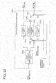
- the feature reproduction unit 1000 includes a code sequence demultiplexing unit 1700, a decoding unit 1110, a decoding unit 1510, a feature difference decoding unit 1530, a feature addition unit 1240, a switching unit 1740, a switching unit 1750, and a difference encoding index determination unit 1560.
- the connection relation between the decoding unit 1110, the decoding unit 1510, the feature difference decoding unit 1530, and the feature addition unit 1240 is the same as that shown in Fig. 18 .
- the code sequence demultiplexing unit 1700 receives a video descriptor, outputs a separated first feature code sequence to the decoding unit 1110, and also outputs a third feature code sequence to the switching unit 1740. Further, the code sequence demultiplexing unit 1700 outputs edge information to the difference encoding index determination unit 1560, and also outputs mode information to the switching unit 1740 and the switching unit 1750.
- the difference encoding index determination unit 1560 receives the edge information output from the code sequence demultiplexing unit 1700, and outputs difference encoding indexes to the switching unit 1740 and the switching unit 1750.
- the switching unit 1740 outputs the third feature code sequence output from the code sequence demultiplexing unit 1700 to either the feature difference decoding unit 1530 or the decoding unit 1510, according to the difference encoding index output from the difference encoding index determination unit 1560 or the mode information output from the code sequence demultiplexing unit 1700.
- the switching unit 1750 receives the addition result output from the feature addition unit 1240 and the decoding result output from the decoding unit 1510, reconstructs the second feature based on the difference encoding indexes output from the difference encoding index determination unit 1560 and the mode information output from the code sequence demultiplexing unit 1700, and outputs it.
- a video descriptor on which matching is performed is first input to the code sequence demultiplexing unit 1700.
- the code sequence demultiplexing unit 1700 separates a first feature code sequence and a third feature code sequence from the video descriptor by means of a demultiplexing method corresponding to the method used for multiplexing. This operation is the same as that performed by the code sequence demultiplexing unit 1100 of the feature reproduction unit shown in Fig. 14 .
- the separated first feature code sequence and the third feature code sequence are respectively output to the decoding unit 1110 and the switching unit 1740.
- the edge information which is information describing the edge in the screen formed by black regions or an L-shaped region, is also demultiplexed from the video descriptor, and output to the difference encoding index determination unit 1560. Further, the mode information is also demultiplexed from the video descriptor and output to the switching unit 1740 and the switching unit 1750.
- Operation of the decoding unit 1110 is the same as the case of Fig. 14 , and a first feature is output.
- the first feature is also output to the feature addition unit 1240.
- the switching unit 1740 changes the output destination of the third feature code sequence for each dimension of the feature, according to the difference encoding indexes output from the difference encoding index determination unit 1560 and the mode information output from the code sequence demultiplexing unit 1700. If the mode information indicates that the feature included in the third feature code sequence is a feature difference value, the switching unit 1740 outputs the third feature code sequence to the feature difference decoding unit 1530 with respect to the dimensions designated by the difference encoding indexes, while outputs third feature code sequence to the decoding unit 1510 with respect to the dimensions not designated by the difference encoding indexes. On the other hand, if the mode information indicates that the feather included in the third feature code sequence is a second feature, the switching unit 1740 outputs the third feature code sequence to the decoding unit 1510.
- the switching unit 1750 switches the output destination of the second feature according to the difference encoding indexes output from the difference encoding index determination unit 1560 and the mode information output from the code sequence demultiplexing unit 1700. If the mode information indicates that the feature included in the third feature code sequence is a feature difference value, the switching unit 1750 outputs the addition result output from the feature addition unit 1240 as a second feature with respect to the dimensions included in the difference encoding indexes, while outputs the decoding result output from the decoding unit 1510 as a second feature with respect to the dimensions not included in the difference encoding indexes. On the other hand, if the mode information indicates that the feature included in the third feature code sequence is a second feature, the switching unit 1750 outputs the decoding result output from the decoding unit 1510 as a second feature.
- the feature reproduction unit shown in Fig. 21 provides a means for separating the features combined by the feature combining unit 240 shown in Fig. 10 .
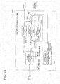
- the feature reproduction unit 1000 includes a code sequence demultiplexing unit 1800, a decoding unit 1110, a decoding unit 1510, a feature difference decoding unit 1530, a feature addition unit 1240, a switching unit 1740, and a switching unit 1750.
- the configuration thereof is similar to that of the case of Fig. 20 except for the code sequence demultiplexing unit 1800, the switching unit 1740, and the switching unit 1750.
- the code sequence demultiplexing unit 1800 receives a video descriptor, outputs a separated first feature code sequence to the decoding unit 1110, and also outputs a third feature code sequence to the switching unit 1540. Further, the code sequence demultiplexing unit 1800 outputs difference encoding indexes and mode information to the switching unit 1740 and the switching unit 1750.
- the switching unit 1740 outputs the third feature code sequence output from the code sequence demultiplexing unit 1800 to either the feature difference decoding unit 1530 or the decoding unit 1510, according to the difference encoding index and the mode information output from the code sequence demultiplexing unit 1800.
- the switching unit 1750 receives the addition result output from the feature addition unit 1240 and the decoding result output from the decoding unit 1510, reconstructs the second feature based on the difference encoding indexes and the mode information output from the code sequence demultiplexing unit 1800, and outputs it.
- Operation other than that of the code sequence demultiplexing unit 1800 is the same as the case shown in Fig. 21 .
- Operation of the code sequence demultiplexing unit 1800 is also similar to that of the code sequence demultiplexing unit 1700 shown in Fig. 21 except for an aspect of demultiplexing a difference encoding indexes instead of edge information.
- the feature reproduction unit 1000 shown in Fig. 22 provides a means for separating the features combined by the feature combining unit 240.
- the feature reproduction unit 1000 includes a code sequence demultiplexing unit 1700, a decoding unit 1110, a decoding unit 1510, a feature difference decoding unit 1530, a feature addition unit 1240, a switching unit 1740, a switching unit 1750, and a difference encoding index determination unit 1560.
- the connection relation between the units other than the code sequence demultiplexing unit 1700 and the feature difference decoding unit 1730 is the same as that shown in Fig. 21 .
- the code sequence demultiplexing unit 1700 receives a video descriptor, outputs a separated first feature code sequence to the decoding unit 1110, and also outputs a third feature code sequence to the switching unit 1540. Further, the code sequence demultiplexing unit 1700 outputs edge information to the difference encoding index determination unit 1560 and the feature difference decoding unit 1730, and outputs mode information to the switching unit 1740 and the switching unit 1750.
- the feature difference decoding unit 1730 receives the third feature code sequence output from the switching unit 1740 an the edge information output from the third feature code sequence, and outputs a feature difference value to the feature addition unit 1240.
- Operation other than that of the feature difference decoding unit 1730 is the same as the case shown in Fig. 21 .
- Operation of the feature difference decoding unit 1730 is also similar to that of the feature difference decoding unit 1530 shown in Fig. 21 except for an aspect of performing decoding by changing the coding parameter according to the edge information.
- the feature reproduction unit shown in Fig. 23 provides a means for separating the features combined by the feature combining unit 240 shown in Fig. 12 .
- the embodiment of the moving image matching device has been described above. With this embodiment, it is possible to perform matching on moving images using a video descriptor extracted by the video descriptor generation device. As such, even if black bars or an L-shaped region is included, it is possible to perform matching without degrading the accuracy.
- Fig. 26 shows an exemplary method of extracting features from a picture.
- pairs of any two regions within a picture are set beforehand, and a difference between the features of the two regions of a pair is obtained as a feature vector.
- respective pairs of regions are indicated as P1, P2, P3, ⁇ , and a feature determined from the n th pair is indicated as Vn.
- Pairs of regions may take various combinations of shapes and positions of regions, as shown in the figure. Also, various methods can be used for calculating the feature Vn from the pair Pn.
- an average value of luminance is calculated in each of a shaded region and a reticulated region of a pair, and a value of the feature Vn is determined from the magnitude relation thereof.
- Vn the absolute value of the difference is smaller than a threshold, Vn is zero, so that the feature Vn is indicated by a ternary values.
- Vn takes a ternary value
- the visual feature extraction unit 120 in Fig. 1 performs the above-described processing on the N pieces of pairs, to thereby obtain feature vectors Vn in N dimensions.
- the video edge detection unit 100 performs Hough transform on each picture, to detect horizontal or vertical lines close to the edge of the video. Then, the video edge detection unit 100 measures continuity between the pictures, and if they continue for the number of pictures which is larger than a threshold, detects them as boundaries of black bar regions or L-shaped regions, and outputs edge information.
- the position-corrected visual feature extraction unit 130 regards the region excluding the edge region as the entire screen to perform the same processing as that performed by the visual feature extraction unit 120 to thereby obtain feature vectors V'n of the N dimensions.
- the feature combining unit 140 or 240 combines the feature vectors Vn and V'n of the N dimensions obtained for each picture to generate a video descriptor.
- the value taken as Dn is a ternary value, although it depends on Vn.
- difference encoding indexes can be determined.
- the video descriptor generation device and the moving image matching device of the present invention are adapted such that the functions thereof can be realized by computers and programs, as well as hardware.
- a program is provided in the form of being written on a computer readable recording medium such as a magnetic disk, a semiconductor memory, or the like, is read by a computer when the computer is started for example, and controls operation of the computer, to thereby allow the computer to function as the video descriptor generation device and the moving image matching device of the above-described embodiments.
- the present invention is applicable to retrieval of similar or identical videos from various videos with high accuracy.
- the present invention is applicable to identification of illegally copied moving images distributed on the networks and identification of commercials distributed on actual airwaves.
Claims (16)
- Dispositif d'appariement d'image animée pour réaliser un appariement entre un premier descripteur vidéo d'une première vidéo et un second descripteur vidéo d'une seconde vidéo, le dispositif comprenant :une première unité de reproduction de particularité (1000) qui reproduit, à partir du premier descripteur vidéo, une première particularité de la première vidéo extraite pour chaque photographie qui est une trame ou un champ de la première vidéo, et une seconde particularité de la première vidéo extraite d'une région définie par un contour d'une image incluse dans la première vidéo ;une seconde unité de reproduction de particularité (1010) qui reproduit, à partir du second descripteur vidéo, une première particularité de la seconde vidéo extraite pour chaque photographie qui est une trame ou un champ de la seconde vidéo, et une seconde particularité de la seconde vidéo extraite d'une région définie par un contour d'une image incluse dans la seconde vidéo ;une première unité d'appariement de particularité (1020) qui réalise un appariement entre la première particularité de la première vidéo et la première particularité de la seconde vidéo pour calculer un premier résultat d'appariement ;une deuxième unité d'appariement de particularité (1030) qui réalise un appariement entre la première particularité de la première vidéo et la seconde particularité de la seconde vidéo pour calculer un deuxième résultat d'appariement ;une troisième unité d'appariement de particularité (1040) qui réalise un appariement entre la seconde particularité de la première vidéo et la première particularité de la seconde vidéo pour calculer un troisième résultat d'appariement ;une quatrième unité d'appariement de particularité (1050) qui réalise un appariement entre la seconde particularité de la première vidéo et la seconde particularité de la seconde vidéo pour calculer un quatrième résultat d'appariement ; etune unité de sélection (1060) qui compare les premier à quatrième résultats d'appariement pour sélectionner un meilleur résultat d'appariement.
- Dispositif d'appariement d'image animée, selon la revendication 1, dans lequel
la première unité de reproduction de particularité et la seconde unité de reproduction de particularité comportent :une unité de démultiplexage de séquence de codes qui démultiplexe le premier descripteur vidéo ou le second descripteur vidéo pour générer une première séquence de codes de particularité obtenue en codant la première particularité de la première vidéo ou de la seconde vidéo extraite pour chaque photographie qui est une trame ou un champ de la première vidéo ou de la seconde vidéo, et une deuxième séquence de codes de particularité obtenue en codant la seconde particularité de la première vidéo ou de la seconde vidéo extraite de la région définie par le contour de l'image incluse dans la première vidéo ou la seconde vidéo ;une première unité de décodage qui décode la première séquence de codes de particularité pour reproduire la première particularité de la première vidéo ou de la seconde vidéo ; etune seconde unité de décodage qui décode la deuxième séquence de codes de particularité pour reproduire la seconde particularité de la première vidéo ou de la seconde vidéo. - Dispositif d'appariement d'image animée selon la revendication 1, dans lequel
la première unité de reproduction de particularité et la seconde unité de reproduction de particularité comportent :une unité de démultiplexage de séquence de codes qui démultiplexe le premier descripteur vidéo ou le second descripteur vidéo pour générer une première séquence de codes de particularité obtenue en codant la première particularité de la première vidéo ou de la seconde vidéo extraite pour chaque photographie qui est une trame ou un champ de la première vidéo ou de la seconde vidéo, et une séquence de codes de valeur de différence de particularité obtenue en codant une valeur de différence de particularité calculée en soustrayant la première particularité de la première vidéo ou de la seconde vidéo de la seconde particularité de la première vidéo ou de la seconde vidéo extraite de la région définie par le contour de l'image incluse dans la première vidéo ou la seconde vidéo ;une première unité de décodage qui décode la première séquence de codes de particularité pour reproduire la première particularité de la première vidéo ou de la seconde vidéo ;une unité de décodage de différence de particularité qui décode la séquence de codes de valeur de différence de particularité pour reproduire la valeur de différence de particularité ; etune unité d'addition qui additionne la première particularité à la valeur de différence de particularité pour calculer la seconde particularité de la première vidéo ou de la seconde vidéo. - Dispositif d'appariement d'image animée selon la revendication 3, dans lequel
l'unité de démultiplexage de séquence de codes démultiplexe également les informations de contour, et
l'unité de décodage de différence de particularité décode la séquence de codes de valeur de différence de particularité d'après les informations de contour pour reproduire la valeur de différence de particularité. - Dispositif d'appariement d'image animée selon la revendication 1, dans lequel
la première unité de reproduction de particularité et la seconde unité de reproduction de particularité comportent :
une unité de démultiplexage de séquence de codes qui démultiplexe le premier descripteur vidéo ou le second descripteur vidéo pour générer :une première séquence de codes de particularité obtenue en codant la première particularité de la première vidéo ou de la seconde vidéo extraite pour chaque photographie qui est une trame ou un champ de la première vidéo ou de la seconde vidéo ;une troisième séquence de codes de particularité comportant l'une, ayant une quantité de code plus petite, d'une deuxième séquence de codes de particularité obtenue en codant la seconde particularité de la première vidéo ou de la seconde vidéo extraite de la région définie par le contour de l'image incluse dans la première vidéo ou la seconde vidéo et une séquence de codes de valeur de différence de particularité obtenue en codant une valeur de différence de particularité calculée en soustrayant la première particularité de la première vidéo ou la seconde vidéo de la seconde particularité ; etdes informations de mode indiquant si la particularité incluse dans la troisième séquence de codes de particularité est la valeur de différence de particularité ou la seconde particularité ;une première unité de décodage qui décode la première séquence de codes de particularité pour reproduire la première particularité de la première vidéo ou de la seconde vidéo ;une première unité de commutation qui reçoit la troisième séquence de codes de particularité, et commute une destination de sortie de la troisième séquence de codes de particularité d'après les informations de mode ;une unité de décodage de différence de particularité qui décode la troisième séquence de codes de particularité fournie en sortie à partir de la première unité de commutation pour reproduire la valeur de différence de particularité ;une seconde unité de décodage qui décode la troisième séquence de codes de particularité fournie en sortie à partir de la première unité de commutation pour reproduire la seconde particularité ;une unité d'addition qui additionne la première particularité à la valeur de différence de particularité pour calculer la seconde particularité ; etune seconde unité de commutation qui combine la seconde particularité fournie en sortie à partir de l'unité d'addition et la seconde particularité fournie en sortie à partir de la seconde unité de décodage tout en réalisant une commutation selon les informations de mode, et fournit en sortie la seconde particularité de la première vidéo ou de la seconde vidéo. - Dispositif d'appariement d'image animée, selon la revendication 1, dans lequel
la première unité de reproduction de particularité et la seconde unité de reproduction de particularité comportent :
une unité de démultiplexage de séquence de codes qui démultiplexe le premier descripteur vidéo ou le second descripteur vidéo, et fournit en sortie :l'une des informations de contour et un indice de codage de différence qui est une information déterminée à partir des informations de contour et indique un indice d'un élément auquel le codage de différence est appliqué parmi des éléments respectifs d'un vecteur de particularité ;une première séquence de codes de particularité obtenue en codant la première particularité de la première vidéo ou de la seconde vidéo extraite pour chaque photographie qui est une trame ou un champ de la première vidéo ou de la seconde vidéo ; etune troisième séquence de codes de particularité comportant l'une, déterminée par les informations de contour ou les informations d'indice de codage de différence, d'une deuxième séquence de codes de particularité obtenue en codant la seconde particularité de la première vidéo ou de la seconde vidéo extraite d'une région définie par un contour d'une image incluse dans la première vidéo ou la seconde vidéo, et une séquence de codes de valeur de différence de particularité obtenue en codant une valeur de différence de particularité calculée en soustrayant la première particularité de la première vidéo ou de la seconde vidéo extraite pour chaque photographie qui est une trame ou un champ de la première vidéo ou de la seconde vidéo de la seconde particularité ;une unité de détermination d'indice de codage de différence qui détermine, si l'unité de démultiplexage de séquence de codes fournit en sortie les informations de contour, un indice d'un élément auquel le codage de différence est appliqué parmi les éléments respectifs du vecteur de particularité à partir des informations de contour, et le fournit en sortie en tant qu'informations d'indice de codage de différence ;une première unité de décodage qui décode la première séquence de codes de particularité pour reproduire la première particularité de la première vidéo ou de la seconde vidéo ;une première unité de commutation qui reçoit la troisième séquence de codes de particularité et commute une destination de sortie de la troisième séquence de codes de particularité d'après les informations d'indice de différence ;une unité de décodage de différence de particularité qui décode la troisième séquence de codes de particularité fournie en sortie à partir de la première unité de commutation pour reproduire la valeur de différence de particularité ;une seconde unité de décodage qui décode la troisième séquence de codes de particularité fournie en sortie à partir de la première unité de commutation pour reproduire la seconde particularité ;une unité d'addition qui additionne la première particularité à la valeur de différence de particularité pour calculer la seconde particularité ; etune seconde unité de commutation qui combine la seconde particularité fournie en sortie à partir de l'unité d'addition et la seconde particularité fournie en sortie à partir de la seconde unité de décodage tout en réalisant une commutation selon les informations d'indice de codage de différence, et fournit en sortie la seconde particularité de la première vidéo ou de la seconde vidéo. - Dispositif d'appariement d'image animée, selon la revendication 1, dans lequel
la première unité de reproduction de particularité et la seconde unité de reproduction de particularité comportent :
une unité de démultiplexage de séquence de codes qui démultiplexe le premier descripteur vidéo ou le second descripteur vidéo, et fournit en sortie :l'une des informations de contour et un indice de codage de différence qui est une information déterminée à partir des informations de contour et indique un indice d'un élément auquel le codage de différence est appliqué parmi des éléments respectifs d'un vecteur de particularité ;une première séquence de codes de particularité obtenue en codant la première particularité de la première vidéo ou de la seconde vidéo extraite pour chaque photographie qui est une trame ou un champ de la première vidéo ou de la seconde vidéo ;une troisième séquence de codes de particularité comportant, d'une deuxième séquence de codes de particularité et d'une séquence de codes de différence de particularité, la deuxième séquence de codes de particularité pour un élément d'un indice qui n'est pas désigné dans les informations d'indice de codage de différence, tout en incluant l'une de la deuxième séquence de codes de particularité et de la séquence de codes de différence de particularité ayant une quantité de code plus petite pour l'élément de l'indice désigné dans les informations d'indice de codage de différence, la deuxième séquence de codes de particularité étant obtenue en codant la seconde particularité de la première vidéo ou de la seconde vidéo extraite d'une région où une vidéo existe réellement au sein d'une photographie de la première vidéo ou de la seconde vidéo définie en utilisant les informations de contour indiquant un contour de l'image détectée à partir de la première vidéo ou de la seconde vidéo, et la séquence de codes de différence de particularité étant obtenue en codant une valeur de différence de particularité calculée en soustrayant la première particularité de la première vidéo ou de la seconde vidéo de la seconde particularité ; etdes informations de mode indiquant si la deuxième séquence de codes de particularité ou la séquence de codes de différence de particularité est incluse pour l'élément de l'indice désigné dans les informations d'indice de codage de différence ;une unité de détermination d'indice de codage de différence qui détermine, si l'unité de démultiplexage de séquence de codes fournit en sortie les informations de contour, un indice d'un élément auquel le codage de différence est appliqué parmi les éléments respectifs du vecteur de particularité à partir des informations de contour, et le fournit en sortie en tant qu'informations d'indice de codage de différence ;une première unité de décodage qui décode la première séquence de codes de particularité pour reproduire la première particularité de la première vidéo ou de la seconde vidéo ;une première unité de commutation qui reçoit la troisième séquence de codes de particularité et commute une destination de sortie de la troisième séquence de codes de particularité d'après les informations d'indice de codage de différence et les informations de mode ;une unité de décodage de différence de particularité qui décode la troisième séquence de codes de particularité fournie en sortie à partir de la première unité de commutation pour reproduire la valeur de différence de particularité ;une seconde unité de décodage qui décode la troisième séquence de codes de particularité fournie en sortie à partir de la première unité de commutation pour reproduire la seconde particularité ;une unité d'addition qui additionne la première particularité à la valeur de différence de particularité pour calculer la seconde particularité ; etune seconde unité de commutation qui combine la seconde particularité fournie en sortie à partir de l'unité d'addition et la seconde particularité fournie en sortie à partir de la seconde unité de décodage tout en réalisant une commutation selon les informations d'indice de différence et les informations de mode, et fournit en sortie la seconde particularité de la première vidéo ou de la seconde vidéo. - Dispositif d'appariement d'image animée, selon la revendication 6 ou 7, dans lequel
l'unité de décodage de différence de particularité décode la séquence de codes de valeur de différence de particularité d'après les informations de contour pour reproduire la valeur de différence de particularité. - Procédé d'appariement d'image animée, comprenant : la reproduction (1000), à partir d'un premier descripteur vidéo, d'une première particularité d'une première vidéo extraite pour chaque photographie qui est une trame ou un champ de la première vidéo, et d'une seconde particularité de la première vidéo extraite d'une région définie par un contour d'une image incluse dans la première vidéo ;
la reproduction (1010), à partir d'un second descripteur vidéo, d'une première particularité d'une seconde vidéo extraite pour chaque photographie qui est une trame ou un champ de la seconde vidéo, et d'une seconde particularité de la seconde vidéo extraite d'une région définie par un contour d'une image incluse dans la seconde vidéo ;
la réalisation d'un appariement (1020) entre la première particularité de la première vidéo et la première particularité de la seconde vidéo pour calculer un premier résultat d'appariement ;
la réalisation d'un appariement (1030) entre la première particularité de la première vidéo et la seconde particularité de la seconde vidéo pour calculer un deuxième résultat d'appariement ;
la réalisation d'un appariement (1040) entre la seconde particularité de la première vidéo et la première particularité de la seconde vidéo pour calculer un troisième résultat d'appariement ;
la réalisation d'un appariement (1050) entre la seconde particularité de la première vidéo et la seconde particularité de la seconde vidéo pour calculer un quatrième résultat d'appariement ; et
la comparaison (1060) des premier à quatrième résultats d'appariement pour sélectionner un meilleur résultat d'appariement. - Procédé d'appariement d'image animée, selon la revendication 9, dans lequel la reproduction de la première particularité et de la seconde particularité de la première vidéo et de la seconde vidéo comporte :le démultiplexage du premier descripteur vidéo ou du second descripteur vidéo pour générer une première séquence de codes de particularité obtenue en codant la première particularité de la première vidéo ou de la seconde vidéo extraite pour chaque photographie qui est une trame ou un champ de la première vidéo ou de la seconde vidéo, et une deuxième séquence de codes de particularité obtenue en codant la seconde particularité de la première vidéo ou de la seconde vidéo extraite de la région définie par le contour de l'image incluse dans la première vidéo ou la seconde vidéo ;le décodage de la première séquence de codes de particularité pour reproduire la première particularité de la première vidéo ou de la seconde vidéo ; etle décodage de la deuxième séquence de codes de particularité pour reproduire la seconde particularité de la première vidéo ou de la seconde vidéo.
- Procédé d'appariement d'image animée selon la revendication 9, dans lequel la reproduction de la première particularité et de la seconde particularité de la première vidéo et de la seconde vidéo comporte :le démultiplexage du premier descripteur vidéo ou du second descripteur vidéo pour générer une première séquence de codes de particularité obtenue en codant la première particularité de la première vidéo ou de la seconde vidéo extraite pour chaque photographie qui est une trame ou un champ de la première vidéo ou de la seconde vidéo, et une séquence de codes de valeur de différence de particularité obtenue en codant une valeur de différence de particularité calculée en soustrayant la première particularité de la première vidéo ou de la seconde vidéo de la seconde particularité de la première vidéo ou de la seconde vidéo extraite de la région définie par le contour de l'image incluse dans la première vidéo ou la seconde vidéo ;le décodage de la première séquence de codes de particularité pour reproduire la première particularité de la première vidéo ou de la seconde vidéo ;le décodage de la séquence de codes de valeur de différence de particularité pour reproduire la valeur de différence de particularité ; etl'addition de la première particularité à la valeur de différence de particularité pour calculer la seconde particularité de la première vidéo ou de la seconde vidéo.
- Procédé d'appariement d'image animée selon la revendication 11, dans lequel le démultiplexage comporte le démultiplexage des informations de contour, et
le décodage de la deuxième séquence de codes de particularité comporte le décodage de la séquence de codes de valeur de différence de particularité d'après les informations de contour pour reproduire la valeur de différence de particularité. - Procédé d'appariement d'image animée selon la revendication 9, dans lequel la reproduction de la première particularité et de la seconde particularité de la première vidéo et de la seconde vidéo comporte :
le démultiplexage du premier descripteur vidéo ou du second descripteur vidéo pour générer :une première séquence de codes de particularité obtenue en codant la première particularité de la première vidéo ou de la seconde vidéo extraite pour chaque photographie qui est une trame ou un champ de la première vidéo ou de la seconde vidéo ;une troisième séquence de codes de particularité incluant l'une, ayant une quantité de code plus petite, d'une deuxième séquence de codes de particularité obtenue en codant la seconde particularité de la première vidéo ou de la seconde vidéo extraite de la région définie par le contour de l'image incluse dans la première vidéo ou la seconde vidéo et d'une séquence de codes de valeur de différence de particularité obtenue en codant une valeur de différence de particularité calculée en soustrayant la première particularité de la première vidéo ou de la seconde vidéo de la seconde particularité ; etdes informations de mode indiquant si la particularité incluse dans la troisième séquence de codes de particularité est la valeur de différence de particularité ou la seconde particularité ;le décodage de la première séquence de codes de particularité pour reproduire la première particularité de la première vidéo ou de la seconde vidéo ;la réception de la troisième séquence de codes de particularité, et la commutation d'une destination de sortie de la troisième séquence de codes de particularité d'après les informations de mode ;le décodage de la troisième séquence de codes de particularité fournie en sortie pour reproduire la valeur de différence de particularité ;le décodage de la troisième séquence de codes de particularité fournie en sortie pour reproduire la seconde particularité ;l'addition de la première particularité à la valeur de différence de particularité pour calculer la seconde particularité ; etla combinaison de la seconde particularité reproduite en décodant la troisième séquence de codes de particularité et la seconde particularité calculée en additionnant la première particularité à la valeur de différence de particularité tout en réalisant une commutation selon les informations de mode, et la fourniture en sortie de la seconde particularité de la première vidéo ou de la seconde vidéo. - Procédé d'appariement d'image animée, selon la revendication 9, dans lequel la reproduction de la première particularité et de la seconde particularité de la première vidéo et de la seconde vidéo comporte :
le démultiplexage du premier descripteur vidéo ou du second descripteur vidéo, et la fourniture en sortie :de l'une des informations de contour et d'un indice de codage de différence qui est une information déterminée à partir des informations de contour et indique un indice d'un élément auquel le codage de différence est appliqué parmi des éléments respectifs d'un vecteur de particularité ;d'une première séquence de codes de particularité obtenue en codant la première particularité de la première vidéo ou de la seconde vidéo extraite pour chaque photographie qui est une trame ou un champ de la première vidéo ou de la seconde vidéo ; etd'une troisième séquence de codes de particularité incluant l'une, déterminée par les informations de contour ou les informations d'indice de codage de différence, d'une deuxième séquence de codes de particularité obtenue en codant la seconde particularité de la première vidéo ou de la seconde vidéo extraite d'une région définie par un contour d'une image incluse dans la première vidéo ou la seconde vidéo, et d'une séquence de codes de valeur de différence de particularité obtenue en codant une valeur de différence de particularité calculée en soustrayant la première particularité de la première vidéo ou de la seconde vidéo extraite pour chaque photographie qui est une trame ou un champ de la première vidéo ou de la seconde vidéo de la seconde particularité ;si les informations de contour sont fournies en sortie, la détermination d'un indice d'un élément auquel le codage de différence est appliqué parmi les éléments respectifs du vecteur de particularité à partir des informations de contour, et sa fourniture en sortie en tant qu'informations d'indice de codage de différence ;le décodage de la première séquence de codes de particularité pour reproduire la première particularité de la première vidéo ou de la seconde vidéo ;la réception de la troisième séquence de codes de particularité et la commutation d'une destination de sortie de la troisième séquence de codes de particularité d'après les informations d'indice de différence ;le décodage de la troisième séquence de codes de particularité fournie en sortie pour reproduire la valeur de différence de particularité ;le décodage de la troisième séquence de codes de particularité fournie en sortie pour reproduire la seconde particularité ;l'addition de la première particularité à la valeur de différence de particularité pour calculer la seconde particularité ; etla combinaison de la seconde particularité reproduite en décodant la troisième séquence de codes de particularité et la seconde particularité calculée en additionnant la première particularité à la valeur de différence de particularité tout en réalisant une commutation selon les informations d'indice de codage de différence, et la fourniture en sortie de la seconde particularité de la première vidéo ou de la seconde vidéo. - Procédé d'appariement d'image animée, selon la revendication 9, dans lequel
la reproduction de la première particularité et de la seconde particularité de la première vidéo et de la seconde vidéo comporte :
le démultiplexage du premier descripteur vidéo ou du second descripteur vidéo, et la fourniture en sortie :de l'une des informations de contour et d'un indice de codage de différence qui est une information déterminée à partir des informations de contour et indique un indice d'un élément auquel le codage de différence est appliqué parmi des éléments respectifs d'un vecteur de particularité ;d'une première séquence de codes de particularité obtenue en codant la première particularité de la première vidéo ou de la seconde vidéo extraite pour chaque photographie qui est une trame ou un champ de la première vidéo ou de la seconde vidéo ;d'une troisième séquence de codes de particularité comportant l'une, d'une deuxième séquence de codes de particularité et d'une séquence de codes de différence de particularité, la deuxième séquence de codes de particularité pour un élément d'un indice qui n'est pas désigné dans les informations d'indice de codage de différence, tout en comportant l'une de la deuxième séquence de codes de particularité et de la séquence de codes de différence de particularité ayant une quantité de code plus petite pour l'élément de l'indice désigné dans les informations d'indice de codage de différence, la deuxième séquence de codes de particularité étant obtenue en codant la seconde particularité de la première vidéo ou de la seconde vidéo extraite d'une région où une vidéo existe réellement au sein d'une photographie de la première vidéo ou de la seconde vidéo définie en utilisant les informations de contour indiquant un contour de l'image détectée à partir de la première vidéo ou de la seconde vidéo, et la séquence de codes de différence de particularité étant obtenue en codant une valeur de différence de particularité calculée en soustrayant la première particularité de la première vidéo ou de la seconde vidéo de la seconde particularité ; etdes informations de mode indiquant si la deuxième séquence de codes de particularité ou la séquence de codes de différence de particularité est incluse pour l'élément de l'indice désigné dans les informations d'indice de codage de différence ;si les informations de contour sont fournies en sortie, la détermination d'un indice d'un élément auquel le codage de différence est appliqué parmi les éléments respectifs du vecteur de particularité à partir des informations de contour, et sa fourniture en sortie en tant qu'informations d'indice de codage de différence ;le décodage de la première séquence de codes de particularité pour reproduire la première particularité de la première vidéo ou de la seconde vidéo ;la réception de la troisième séquence de codes de particularité et la commutation d'une destination de sortie de la troisième séquence de codes de particularité d'après les informations d'indice de codage de différence et les informations de mode ;le décodage de la troisième séquence de codes de particularité fournie en sortie pour reproduire la valeur de différence de particularité ;le décodage de la troisième séquence de codes de particularité fournie en sortie pour reproduire la seconde particularité ;l'addition de la première particularité à la valeur de différence de particularité pour calculer la seconde particularité ; etla combinaison de la seconde particularité reproduite en décodant la troisième séquence de codes de particularité et la seconde particularité calculée en additionnant la première particularité à la valeur de différence de particularité tout en réalisant une commutation selon les informations d'indice de différence et les informations de mode, et la fourniture en sortie de la seconde particularité de la première vidéo ou de la seconde vidéo. - Procédé d'appariement d'image animée, selon la revendication 14 ou 15, dans lequel la reproduction de la valeur de différence de particularité en décodant la troisième séquence de codes de particularité comporte le décodage de la séquence de codes de valeur de différence de particularité d'après les informations de contour pour reproduire la valeur de différence de particularité.
Applications Claiming Priority (3)
| Application Number | Priority Date | Filing Date | Title |
|---|---|---|---|
| JP2009012812 | 2009-01-23 | ||
| EP10733345A EP2391122A4 (fr) | 2009-01-23 | 2010-01-20 | Dispositif pour générer un descripteur vidéo |
| PCT/JP2010/000276 WO2010084737A1 (fr) | 2009-01-23 | 2010-01-20 | Dispositif pour générer un descripteur vidéo |
Related Parent Applications (2)
| Application Number | Title | Priority Date | Filing Date |
|---|---|---|---|
| EP10733345A Division EP2391122A4 (fr) | 2009-01-23 | 2010-01-20 | Dispositif pour générer un descripteur vidéo |
| EP10733345.2 Division | 2010-01-20 |
Publications (3)
| Publication Number | Publication Date |
|---|---|
| EP2434416A2 EP2434416A2 (fr) | 2012-03-28 |
| EP2434416A3 EP2434416A3 (fr) | 2012-08-29 |
| EP2434416B1 true EP2434416B1 (fr) | 2018-08-15 |
Family
ID=42355795
Family Applications (2)
| Application Number | Title | Priority Date | Filing Date |
|---|---|---|---|
| EP10733345A Ceased EP2391122A4 (fr) | 2009-01-23 | 2010-01-20 | Dispositif pour générer un descripteur vidéo |
| EP11189661.9A Not-in-force EP2434416B1 (fr) | 2009-01-23 | 2010-01-20 | Dispositif pour générer un descripteur vidéo |
Family Applications Before (1)
| Application Number | Title | Priority Date | Filing Date |
|---|---|---|---|
| EP10733345A Ceased EP2391122A4 (fr) | 2009-01-23 | 2010-01-20 | Dispositif pour générer un descripteur vidéo |
Country Status (6)
| Country | Link |
|---|---|
| US (1) | US9367616B2 (fr) |
| EP (2) | EP2391122A4 (fr) |
| JP (2) | JP4883226B2 (fr) |
| KR (1) | KR101289928B1 (fr) |
| CN (2) | CN102292979B (fr) |
| WO (1) | WO2010084737A1 (fr) |
Families Citing this family (16)
| Publication number | Priority date | Publication date | Assignee | Title |
|---|---|---|---|---|
| WO2010084737A1 (fr) | 2009-01-23 | 2010-07-29 | 日本電気株式会社 | Dispositif pour générer un descripteur vidéo |
| US9258564B2 (en) * | 2012-02-07 | 2016-02-09 | Stmicroelectronics S.R.L. | Visual search system architectures based on compressed or compact feature descriptors |
| CN108197631B (zh) * | 2012-07-23 | 2022-06-28 | 苹果公司 | 提供图像特征描述符的方法 |
| CN104142939B (zh) * | 2013-05-07 | 2019-07-02 | 杭州智棱科技有限公司 | 一种基于运动特征信息匹配特征码的方法与设备 |
| CN104144520A (zh) | 2013-05-07 | 2014-11-12 | 李东舸 | 一种设备间建立连接的方法、装置与系统 |
| KR20160105793A (ko) | 2014-01-07 | 2016-09-07 | 캐논 가부시끼가이샤 | 인터-계층 종속성을 인코딩하기 위한 방법, 디바이스, 및 컴퓨터 프로그램 |
| CN106716450B (zh) * | 2014-05-06 | 2020-05-19 | 河谷控股Ip有限责任公司 | 利用边缘向量的基于图像的特征检测 |
| US9544621B2 (en) | 2014-09-17 | 2017-01-10 | Google Inc. | Identification of captured videos |
| US10095786B2 (en) | 2015-04-09 | 2018-10-09 | Oath Inc. | Topical based media content summarization system and method |
| JP6409792B2 (ja) * | 2016-02-10 | 2018-10-24 | 三菱電機株式会社 | 画像特徴記述子符号化装置、画像特徴記述子復号装置、画像特徴記述子符号化方法及び画像特徴記述子復号方法 |
| CN106028158B (zh) * | 2016-05-26 | 2019-04-16 | 成都掌中全景信息技术有限公司 | 一种基于多视频源的进度识别方法 |
| JP6530002B2 (ja) * | 2017-04-12 | 2019-06-12 | 日本電信電話株式会社 | コンテンツ探索装置、コンテンツ探索方法、プログラム |
| CN108876813B (zh) * | 2017-11-01 | 2021-01-26 | 北京旷视科技有限公司 | 用于视频中物体检测的图像处理方法、装置及设备 |
| CN110758354B (zh) * | 2019-10-16 | 2020-07-17 | 安徽诺乐知识产权服务有限公司 | 基于大数据采集的车辆紧急制动执行系统 |
| US11263261B2 (en) * | 2020-02-14 | 2022-03-01 | Alibaba Group Holding Limited | Method and system for characteristic-based video processing |
| CN113810695A (zh) * | 2020-06-15 | 2021-12-17 | 中国电信股份有限公司 | 视频编码方法、装置及计算机可读存储介质 |
Family Cites Families (17)
| Publication number | Priority date | Publication date | Assignee | Title |
|---|---|---|---|---|
| JP3780623B2 (ja) | 1997-05-16 | 2006-05-31 | 株式会社日立製作所 | 動画像の記述方法 |
| JP2002117037A (ja) * | 2000-10-06 | 2002-04-19 | Nec Corp | 画像検索装置、並びに画像検索方法及びこれが書き込まれた記録媒体 |
| JP2003122758A (ja) * | 2001-10-11 | 2003-04-25 | Canon Inc | 画像検索方法及び装置 |
| JP2003319177A (ja) * | 2002-04-22 | 2003-11-07 | Canon Inc | 量子化処理装置及び方法とそれを用いたインクジェット記録装置 |
| US7321623B2 (en) * | 2002-10-01 | 2008-01-22 | Avocent Corporation | Video compression system |
| JP3793142B2 (ja) * | 2002-11-15 | 2006-07-05 | 株式会社東芝 | 動画像加工方法及び装置 |
| US7657126B2 (en) * | 2005-05-09 | 2010-02-02 | Like.Com | System and method for search portions of objects in images and features thereof |
| JP4920928B2 (ja) * | 2005-08-08 | 2012-04-18 | キヤノン株式会社 | 画像処理装置及びその制御方法、プログラム |
| US8145656B2 (en) * | 2006-02-07 | 2012-03-27 | Mobixell Networks Ltd. | Matching of modified visual and audio media |
| WO2007148264A1 (fr) | 2006-06-20 | 2007-12-27 | Koninklijke Philips Electronics N.V. | Génération d'empreintes de signaux vidéo |
| US8676810B2 (en) * | 2006-07-31 | 2014-03-18 | Ricoh Co., Ltd. | Multiple index mixed media reality recognition using unequal priority indexes |
| JP4985993B2 (ja) * | 2006-08-10 | 2012-07-25 | 日本電気株式会社 | オブジェクト領域抽出装置 |
| TWI442773B (zh) | 2006-11-30 | 2014-06-21 | Dolby Lab Licensing Corp | 抽取視訊與音訊信號內容之特徵以提供此等信號之可靠識別的技術 |
| JP2009012812A (ja) | 2007-07-05 | 2009-01-22 | Sekisui Film Kk | 合成樹脂フィルム |
| US8498487B2 (en) * | 2008-08-20 | 2013-07-30 | Sri International | Content-based matching of videos using local spatio-temporal fingerprints |
| WO2010084737A1 (fr) | 2009-01-23 | 2010-07-29 | 日本電気株式会社 | Dispositif pour générer un descripteur vidéo |
| US8260055B2 (en) * | 2009-03-27 | 2012-09-04 | The Nielsen Company (Us), Llc | Methods and apparatus for identifying primary media content in a post-production media content presentation |
-
2010
- 2010-01-20 WO PCT/JP2010/000276 patent/WO2010084737A1/fr active Application Filing
- 2010-01-20 US US13/144,758 patent/US9367616B2/en active Active
- 2010-01-20 CN CN201080005232.6A patent/CN102292979B/zh not_active Expired - Fee Related
- 2010-01-20 JP JP2010547432A patent/JP4883226B2/ja not_active Expired - Fee Related
- 2010-01-20 EP EP10733345A patent/EP2391122A4/fr not_active Ceased
- 2010-01-20 KR KR20117017376A patent/KR101289928B1/ko active IP Right Grant
- 2010-01-20 CN CN201510047532.5A patent/CN104537127B/zh not_active Expired - Fee Related
- 2010-01-20 EP EP11189661.9A patent/EP2434416B1/fr not_active Not-in-force
-
2011
- 2011-11-30 JP JP2011262738A patent/JP2012084164A/ja active Pending
Non-Patent Citations (1)
| Title |
|---|
| None * |
Also Published As
| Publication number | Publication date |
|---|---|
| CN104537127B (zh) | 2018-04-10 |
| EP2391122A1 (fr) | 2011-11-30 |
| CN102292979B (zh) | 2015-02-04 |
| EP2391122A4 (fr) | 2012-09-05 |
| JP2012084164A (ja) | 2012-04-26 |
| WO2010084737A1 (fr) | 2010-07-29 |
| CN104537127A (zh) | 2015-04-22 |
| KR20110106414A (ko) | 2011-09-28 |
| EP2434416A3 (fr) | 2012-08-29 |
| KR101289928B1 (ko) | 2013-07-25 |
| JPWO2010084737A1 (ja) | 2012-07-12 |
| JP4883226B2 (ja) | 2012-02-22 |
| CN102292979A (zh) | 2011-12-21 |
| US9367616B2 (en) | 2016-06-14 |
| EP2434416A2 (fr) | 2012-03-28 |
| US20110274355A1 (en) | 2011-11-10 |
Similar Documents
| Publication | Publication Date | Title |
|---|---|---|
| EP2434416B1 (fr) | Dispositif pour générer un descripteur vidéo | |
| KR101369915B1 (ko) | 영상 식별자 추출 장치 | |
| CN102187672B (zh) | 压缩视频中的语法元素的兼容cabac/avc的水印加注 | |
| KR100865248B1 (ko) | 비디오 신호에서의 자막 검출 | |
| US8478050B2 (en) | Video signature generation device and method, video signature matching device and method, and program | |
| EP3718306B1 (fr) | Raffinement d'agrégats pour synthèse de texture en codage vidéo | |
| KR20140058643A (ko) | 강건한 낮은 복잡도 비디오 핑거프린팅을 위한 장치 및 방법 | |
| KR101281850B1 (ko) | 영상 디스크립터 생성 장치 | |
| KR20110110252A (ko) | 영상 시그니처 생성 디바이스 | |
| JP5644505B2 (ja) | 照合加重情報抽出装置 | |
| CN103650491A (zh) | 用于解码立体视频信号的方法和系统 | |
| JP2005175943A (ja) | 画像処理装置、画像処理方法、コンピュータプログラム及び記録媒体 |
Legal Events
| Date | Code | Title | Description |
|---|---|---|---|
| PUAI | Public reference made under article 153(3) epc to a published international application that has entered the european phase |
Free format text: ORIGINAL CODE: 0009012 |
|
| AC | Divisional application: reference to earlier application |
Ref document number: 2391122 Country of ref document: EP Kind code of ref document: P |
|
| AK | Designated contracting states |
Kind code of ref document: A2 Designated state(s): AT BE BG CH CY CZ DE DK EE ES FI FR GB GR HR HU IE IS IT LI LT LU LV MC MK MT NL NO PL PT RO SE SI SK SM TR |
|
| PUAL | Search report despatched |
Free format text: ORIGINAL CODE: 0009013 |
|
| AK | Designated contracting states |
Kind code of ref document: A3 Designated state(s): AT BE BG CH CY CZ DE DK EE ES FI FR GB GR HR HU IE IS IT LI LT LU LV MC MK MT NL NO PL PT RO SE SI SK SM TR |
|
| RIC1 | Information provided on ipc code assigned before grant |
Ipc: G06F 17/30 20060101AFI20120726BHEP Ipc: G06K 9/00 20060101ALI20120726BHEP |
|
| 17P | Request for examination filed |
Effective date: 20130228 |
|
| GRAP | Despatch of communication of intention to grant a patent |
Free format text: ORIGINAL CODE: EPIDOSNIGR1 |
|
| STAA | Information on the status of an ep patent application or granted ep patent |
Free format text: STATUS: GRANT OF PATENT IS INTENDED |
|
| RIC1 | Information provided on ipc code assigned before grant |
Ipc: G06K 9/46 20060101AFI20180129BHEP Ipc: G06K 9/50 20060101ALI20180129BHEP |
|
| INTG | Intention to grant announced |
Effective date: 20180219 |
|
| GRAJ | Information related to disapproval of communication of intention to grant by the applicant or resumption of examination proceedings by the epo deleted |
Free format text: ORIGINAL CODE: EPIDOSDIGR1 |
|
| STAA | Information on the status of an ep patent application or granted ep patent |
Free format text: STATUS: REQUEST FOR EXAMINATION WAS MADE |
|
| GRAR | Information related to intention to grant a patent recorded |
Free format text: ORIGINAL CODE: EPIDOSNIGR71 |
|
| GRAS | Grant fee paid |
Free format text: ORIGINAL CODE: EPIDOSNIGR3 |
|
| STAA | Information on the status of an ep patent application or granted ep patent |
Free format text: STATUS: GRANT OF PATENT IS INTENDED |
|
| GRAA | (expected) grant |
Free format text: ORIGINAL CODE: 0009210 |
|
| STAA | Information on the status of an ep patent application or granted ep patent |
Free format text: STATUS: THE PATENT HAS BEEN GRANTED |
|
| INTC | Intention to grant announced (deleted) | ||
| RIC1 | Information provided on ipc code assigned before grant |
Ipc: G06F 17/30 20060101AFI20180625BHEP Ipc: G06K 9/46 20060101ALI20180625BHEP Ipc: G06K 9/50 20060101ALI20180625BHEP Ipc: G06K 9/00 20060101ALI20180625BHEP |
|
| INTG | Intention to grant announced |
Effective date: 20180704 |
|
| AC | Divisional application: reference to earlier application |
Ref document number: 2391122 Country of ref document: EP Kind code of ref document: P |
|
| AK | Designated contracting states |
Kind code of ref document: B1 Designated state(s): AT BE BG CH CY CZ DE DK EE ES FI FR GB GR HR HU IE IS IT LI LT LU LV MC MK MT NL NO PL PT RO SE SI SK SM TR |
|
| REG | Reference to a national code |
Ref country code: AT Ref legal event code: REF Ref document number: 1030591 Country of ref document: AT Kind code of ref document: T Effective date: 20180815 Ref country code: GB Ref legal event code: FG4D Ref country code: CH Ref legal event code: EP |
|
| REG | Reference to a national code |
Ref country code: IE Ref legal event code: FG4D |
|
| REG | Reference to a national code |
Ref country code: DE Ref legal event code: R096 Ref document number: 602010052875 Country of ref document: DE |
|
| REG | Reference to a national code |
Ref country code: DE Ref legal event code: R079 Ref document number: 602010052875 Country of ref document: DE Free format text: PREVIOUS MAIN CLASS: G06F0017300000 Ipc: G06F0016000000 |
|
| REG | Reference to a national code |
Ref country code: NL Ref legal event code: MP Effective date: 20180815 |
|
| REG | Reference to a national code |
Ref country code: LT Ref legal event code: MG4D |
|
| REG | Reference to a national code |
Ref country code: AT Ref legal event code: MK05 Ref document number: 1030591 Country of ref document: AT Kind code of ref document: T Effective date: 20180815 |
|
| PG25 | Lapsed in a contracting state [announced via postgrant information from national office to epo] |
Ref country code: IS Free format text: LAPSE BECAUSE OF FAILURE TO SUBMIT A TRANSLATION OF THE DESCRIPTION OR TO PAY THE FEE WITHIN THE PRESCRIBED TIME-LIMIT Effective date: 20181215 Ref country code: NO Free format text: LAPSE BECAUSE OF FAILURE TO SUBMIT A TRANSLATION OF THE DESCRIPTION OR TO PAY THE FEE WITHIN THE PRESCRIBED TIME-LIMIT Effective date: 20181115 Ref country code: BG Free format text: LAPSE BECAUSE OF FAILURE TO SUBMIT A TRANSLATION OF THE DESCRIPTION OR TO PAY THE FEE WITHIN THE PRESCRIBED TIME-LIMIT Effective date: 20181115 Ref country code: NL Free format text: LAPSE BECAUSE OF FAILURE TO SUBMIT A TRANSLATION OF THE DESCRIPTION OR TO PAY THE FEE WITHIN THE PRESCRIBED TIME-LIMIT Effective date: 20180815 Ref country code: AT Free format text: LAPSE BECAUSE OF FAILURE TO SUBMIT A TRANSLATION OF THE DESCRIPTION OR TO PAY THE FEE WITHIN THE PRESCRIBED TIME-LIMIT Effective date: 20180815 Ref country code: GR Free format text: LAPSE BECAUSE OF FAILURE TO SUBMIT A TRANSLATION OF THE DESCRIPTION OR TO PAY THE FEE WITHIN THE PRESCRIBED TIME-LIMIT Effective date: 20181116 Ref country code: SE Free format text: LAPSE BECAUSE OF FAILURE TO SUBMIT A TRANSLATION OF THE DESCRIPTION OR TO PAY THE FEE WITHIN THE PRESCRIBED TIME-LIMIT Effective date: 20180815 Ref country code: LT Free format text: LAPSE BECAUSE OF FAILURE TO SUBMIT A TRANSLATION OF THE DESCRIPTION OR TO PAY THE FEE WITHIN THE PRESCRIBED TIME-LIMIT Effective date: 20180815 Ref country code: FI Free format text: LAPSE BECAUSE OF FAILURE TO SUBMIT A TRANSLATION OF THE DESCRIPTION OR TO PAY THE FEE WITHIN THE PRESCRIBED TIME-LIMIT Effective date: 20180815 |
|
| PG25 | Lapsed in a contracting state [announced via postgrant information from national office to epo] |
Ref country code: LV Free format text: LAPSE BECAUSE OF FAILURE TO SUBMIT A TRANSLATION OF THE DESCRIPTION OR TO PAY THE FEE WITHIN THE PRESCRIBED TIME-LIMIT Effective date: 20180815 Ref country code: ES Free format text: LAPSE BECAUSE OF FAILURE TO SUBMIT A TRANSLATION OF THE DESCRIPTION OR TO PAY THE FEE WITHIN THE PRESCRIBED TIME-LIMIT Effective date: 20180815 Ref country code: HR Free format text: LAPSE BECAUSE OF FAILURE TO SUBMIT A TRANSLATION OF THE DESCRIPTION OR TO PAY THE FEE WITHIN THE PRESCRIBED TIME-LIMIT Effective date: 20180815 |
|
| PG25 | Lapsed in a contracting state [announced via postgrant information from national office to epo] |
Ref country code: EE Free format text: LAPSE BECAUSE OF FAILURE TO SUBMIT A TRANSLATION OF THE DESCRIPTION OR TO PAY THE FEE WITHIN THE PRESCRIBED TIME-LIMIT Effective date: 20180815 Ref country code: PL Free format text: LAPSE BECAUSE OF FAILURE TO SUBMIT A TRANSLATION OF THE DESCRIPTION OR TO PAY THE FEE WITHIN THE PRESCRIBED TIME-LIMIT Effective date: 20180815 Ref country code: RO Free format text: LAPSE BECAUSE OF FAILURE TO SUBMIT A TRANSLATION OF THE DESCRIPTION OR TO PAY THE FEE WITHIN THE PRESCRIBED TIME-LIMIT Effective date: 20180815 Ref country code: IT Free format text: LAPSE BECAUSE OF FAILURE TO SUBMIT A TRANSLATION OF THE DESCRIPTION OR TO PAY THE FEE WITHIN THE PRESCRIBED TIME-LIMIT Effective date: 20180815 Ref country code: CZ Free format text: LAPSE BECAUSE OF FAILURE TO SUBMIT A TRANSLATION OF THE DESCRIPTION OR TO PAY THE FEE WITHIN THE PRESCRIBED TIME-LIMIT Effective date: 20180815 |
|
| REG | Reference to a national code |
Ref country code: DE Ref legal event code: R097 Ref document number: 602010052875 Country of ref document: DE |
|
| PG25 | Lapsed in a contracting state [announced via postgrant information from national office to epo] |
Ref country code: SM Free format text: LAPSE BECAUSE OF FAILURE TO SUBMIT A TRANSLATION OF THE DESCRIPTION OR TO PAY THE FEE WITHIN THE PRESCRIBED TIME-LIMIT Effective date: 20180815 Ref country code: SK Free format text: LAPSE BECAUSE OF FAILURE TO SUBMIT A TRANSLATION OF THE DESCRIPTION OR TO PAY THE FEE WITHIN THE PRESCRIBED TIME-LIMIT Effective date: 20180815 Ref country code: DK Free format text: LAPSE BECAUSE OF FAILURE TO SUBMIT A TRANSLATION OF THE DESCRIPTION OR TO PAY THE FEE WITHIN THE PRESCRIBED TIME-LIMIT Effective date: 20180815 |
|
| PLBE | No opposition filed within time limit |
Free format text: ORIGINAL CODE: 0009261 |
|
| STAA | Information on the status of an ep patent application or granted ep patent |
Free format text: STATUS: NO OPPOSITION FILED WITHIN TIME LIMIT |
|
| 26N | No opposition filed |
Effective date: 20190516 |
|
| PG25 | Lapsed in a contracting state [announced via postgrant information from national office to epo] |
Ref country code: MC Free format text: LAPSE BECAUSE OF FAILURE TO SUBMIT A TRANSLATION OF THE DESCRIPTION OR TO PAY THE FEE WITHIN THE PRESCRIBED TIME-LIMIT Effective date: 20180815 Ref country code: SI Free format text: LAPSE BECAUSE OF FAILURE TO SUBMIT A TRANSLATION OF THE DESCRIPTION OR TO PAY THE FEE WITHIN THE PRESCRIBED TIME-LIMIT Effective date: 20180815 |
|
| REG | Reference to a national code |
Ref country code: CH Ref legal event code: PL |
|
| PG25 | Lapsed in a contracting state [announced via postgrant information from national office to epo] |
Ref country code: LU Free format text: LAPSE BECAUSE OF NON-PAYMENT OF DUE FEES Effective date: 20190120 |
|
| REG | Reference to a national code |
Ref country code: BE Ref legal event code: MM Effective date: 20190131 |
|
| REG | Reference to a national code |
Ref country code: IE Ref legal event code: MM4A |
|
| PG25 | Lapsed in a contracting state [announced via postgrant information from national office to epo] |
Ref country code: BE Free format text: LAPSE BECAUSE OF NON-PAYMENT OF DUE FEES Effective date: 20190131 |
|
| PG25 | Lapsed in a contracting state [announced via postgrant information from national office to epo] |
Ref country code: CH Free format text: LAPSE BECAUSE OF NON-PAYMENT OF DUE FEES Effective date: 20190131 Ref country code: LI Free format text: LAPSE BECAUSE OF NON-PAYMENT OF DUE FEES Effective date: 20190131 |
|
| PG25 | Lapsed in a contracting state [announced via postgrant information from national office to epo] |
Ref country code: IE Free format text: LAPSE BECAUSE OF NON-PAYMENT OF DUE FEES Effective date: 20190120 |
|
| PGFP | Annual fee paid to national office [announced via postgrant information from national office to epo] |
Ref country code: FR Payment date: 20191216 Year of fee payment: 11 |
|
| PG25 | Lapsed in a contracting state [announced via postgrant information from national office to epo] |
Ref country code: TR Free format text: LAPSE BECAUSE OF FAILURE TO SUBMIT A TRANSLATION OF THE DESCRIPTION OR TO PAY THE FEE WITHIN THE PRESCRIBED TIME-LIMIT Effective date: 20180815 |
|
| PGFP | Annual fee paid to national office [announced via postgrant information from national office to epo] |
Ref country code: GB Payment date: 20200113 Year of fee payment: 11 Ref country code: DE Payment date: 20200107 Year of fee payment: 11 |
|
| PG25 | Lapsed in a contracting state [announced via postgrant information from national office to epo] |
Ref country code: PT Free format text: LAPSE BECAUSE OF FAILURE TO SUBMIT A TRANSLATION OF THE DESCRIPTION OR TO PAY THE FEE WITHIN THE PRESCRIBED TIME-LIMIT Effective date: 20181215 Ref country code: MT Free format text: LAPSE BECAUSE OF NON-PAYMENT OF DUE FEES Effective date: 20190120 |
|
| PG25 | Lapsed in a contracting state [announced via postgrant information from national office to epo] |
Ref country code: CY Free format text: LAPSE BECAUSE OF FAILURE TO SUBMIT A TRANSLATION OF THE DESCRIPTION OR TO PAY THE FEE WITHIN THE PRESCRIBED TIME-LIMIT Effective date: 20180815 |
|
| PG25 | Lapsed in a contracting state [announced via postgrant information from national office to epo] |
Ref country code: HU Free format text: LAPSE BECAUSE OF FAILURE TO SUBMIT A TRANSLATION OF THE DESCRIPTION OR TO PAY THE FEE WITHIN THE PRESCRIBED TIME-LIMIT; INVALID AB INITIO Effective date: 20100120 |
|
| REG | Reference to a national code |
Ref country code: DE Ref legal event code: R119 Ref document number: 602010052875 Country of ref document: DE |
|
| GBPC | Gb: european patent ceased through non-payment of renewal fee |
Effective date: 20210120 |
|
| PG25 | Lapsed in a contracting state [announced via postgrant information from national office to epo] |
Ref country code: FR Free format text: LAPSE BECAUSE OF NON-PAYMENT OF DUE FEES Effective date: 20210131 |
|
| PG25 | Lapsed in a contracting state [announced via postgrant information from national office to epo] |
Ref country code: GB Free format text: LAPSE BECAUSE OF NON-PAYMENT OF DUE FEES Effective date: 20210120 Ref country code: DE Free format text: LAPSE BECAUSE OF NON-PAYMENT OF DUE FEES Effective date: 20210803 |
|
| PG25 | Lapsed in a contracting state [announced via postgrant information from national office to epo] |
Ref country code: MK Free format text: LAPSE BECAUSE OF FAILURE TO SUBMIT A TRANSLATION OF THE DESCRIPTION OR TO PAY THE FEE WITHIN THE PRESCRIBED TIME-LIMIT Effective date: 20180815 |