WO2010082667A1 - 歩数計 - Google Patents
歩数計 Download PDFInfo
- Publication number
- WO2010082667A1 WO2010082667A1 PCT/JP2010/050573 JP2010050573W WO2010082667A1 WO 2010082667 A1 WO2010082667 A1 WO 2010082667A1 JP 2010050573 W JP2010050573 W JP 2010050573W WO 2010082667 A1 WO2010082667 A1 WO 2010082667A1
- Authority
- WO
- WIPO (PCT)
- Prior art keywords
- display
- section
- screen
- counting
- step count
- Prior art date
- Legal status (The legal status is an assumption and is not a legal conclusion. Google has not performed a legal analysis and makes no representation as to the accuracy of the status listed.)
- Ceased
Links
Images









Classifications
-
- G—PHYSICS
- G01—MEASURING; TESTING
- G01C—MEASURING DISTANCES, LEVELS OR BEARINGS; SURVEYING; NAVIGATION; GYROSCOPIC INSTRUMENTS; PHOTOGRAMMETRY OR VIDEOGRAMMETRY
- G01C22/00—Measuring distance traversed on the ground by vehicles, persons, animals or other moving solid bodies, e.g. using odometers, using pedometers
- G01C22/006—Pedometers
Definitions
- This invention relates to a pedometer.
- the pedometer detects the acceleration of the pedestrian in the vertical direction with an acceleration sensor, counts the number of steps (body movement) based on the change in the detected value, and displays the counted number of steps as a numerical value.
- a pedometer can display not only the number of steps but also a large amount of information such as calorie consumption, fat burning amount, walking distance, walking time, and the like.
- some conventional pedometers have a section measurement function that is used when measuring the number of steps or distance in an arbitrary section, in addition to the normal step count measurement function.
- this section measurement function for example, the number of steps and the distance for walking satisfying a predetermined condition such as fast walking can be measured.
- an arbitrary section in which the number of steps and the distance can be measured is limited to one section. For example, when the same section is walked a plurality of times, the section If a memo or the like is not recorded on the spot every time the user walks once, there is a problem that the walking data per one time in the section cannot be understood. For this reason, for example, when walking a predetermined course over a plurality of laps, in order to compare the number of steps per lap, the elapsed time (lap time), etc., a memo or the like is recorded on the spot every time the section is circulated. There was a problem that it was troublesome.
- the present invention measures step data of an arbitrary type (for example, section measurement) in a state not desired by the wearer when counting various types of step data.
- An object is to provide a pedometer that can be stopped.
- Another object of the present invention is to provide a pedometer capable of distinguishing the step count data measured in the section designated by the carrier from other step count data in order to eliminate the above-described problems caused by the prior art.
- a pedometer includes a counting unit that detects the number of steps by walking and counts it as a plurality of step count data, and the plurality of steps counted by the counting unit.
- Step count data storage means for storing data
- display means for displaying the step count data stored by the step count data storage means
- stop operation means for instructing to stop counting one step count data among the plurality of step count data, , Provided.
- the pedometer according to the present invention is characterized in that, in the above-mentioned invention, the pedometer includes stop cancellation means for canceling the stop by the stop operation means and canceling the stop of counting of the step count data.
- the pedometer according to the present invention includes, in the above-described invention, section designation receiving means for receiving designation of an arbitrary section, and the step data storage means stores the step count data counted by the counting means as the section. The information is stored for each arbitrary section whose designation is accepted by the designation receiving means.
- the pedometer according to the present invention includes a mode setting unit that receives a setting of a specific walking mode that displays only the count of the number of steps based on the number of steps by walking satisfying a specific condition in the above invention, and the counting unit includes When the setting of the specific walking mode is received by the mode setting means, the step count data based on the number of steps by walking satisfying the specific condition in an arbitrary section received by the section specification receiving means It memorize
- the pedometer according to the present invention is the pedometer according to the invention, wherein the display means counts the number of step data based on the number of steps by walking that satisfies the specific condition in an arbitrary section that has been designated by the section designation accepting means. It is characterized by displaying that it is inside.
- the pedometer according to the present invention is characterized in that, in the above invention, the plurality of step count data is step count data counted in different periods or step count data based on a step count by walking satisfying a specific condition. To do.
- the pedometer according to the present invention further comprises stop time counting means for measuring a time from when stop is instructed by the stop operation means in the above invention, wherein the stop release means is the stop time counting means.
- the stop time counting means is the stop time counting means.
- the pedometer according to the present invention further comprises a measurement time counting means for measuring a time from when the stop cancellation is instructed by the stop cancellation means in the above invention, wherein the stop operation means includes the measurement time counting.
- the stop operation means includes the measurement time counting.
- the pedometer according to the present invention is characterized in that, in the above-mentioned invention, setting means for setting the predetermined time is provided.
- the step number data desired by the wearer is counted among a plurality of step number data such as the step number data of the day, the total number of step data, the step number data of the section measurement, and the step number data for a specific walk
- the measurement can be started or stopped based on the intention of the carrier, and thus the step count data of the section desired by the carrier can be accurately measured. There is an effect.
- the step count data measured in the section designated by the carrier is stored for each section, so that the measurement of the step count data in the section designated by the carrier can be performed There is an effect that it can be distinguished from the measurement of the step count data.
- the pedometer in particular, by storing step count data for walking (for example, jogging) satisfying a specific condition measured in a section designated by the carrier for each section, It is possible to guide the number-of-steps data regarding the exercises performed by the person carrying the carrier consciously.
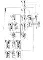
- FIG. 1 is a block diagram showing a hardware configuration of a pedometer according to the first embodiment of the present invention.
- FIG. 2 is a block diagram showing a functional configuration of the pedometer processing apparatus according to the first embodiment of the present invention.
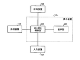
- FIG. 3 is a block diagram showing a functional configuration of the display device of the pedometer according to the first embodiment of the present invention.
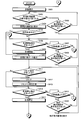
- FIG. 4A is a flowchart of a pedometer counting control process and a display switching control process according to the first embodiment of the present invention.
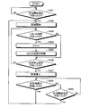
- FIG. 4-2 is a flowchart of another procedure of the pedometer counting control process according to the first embodiment of the present invention.
- FIG. 5 is an explanatory diagram showing the appearance of the pedometer according to the first embodiment of the present invention.
- FIG. 6A is an explanatory diagram of an example (step count display) of display contents of the pedometer according to the first embodiment of the present invention.
- FIG. 6B is an explanatory diagram of a change in display of the goal achievement level information.
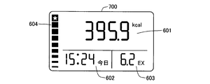
- FIG. 7 is an explanatory diagram showing an example (calorie consumption) of display contents of the pedometer according to the first embodiment of the present invention.
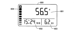
- FIG. 8 is an explanatory diagram showing an example (fat burning amount) of display contents of the pedometer according to the first embodiment of the present invention.
- FIG. 9 is an explanatory diagram showing an example (walking distance) of display contents of the pedometer according to the first embodiment of the present invention.
- FIG. 10 is an explanatory diagram showing an example (walking time) of display contents of the pedometer according to the first embodiment of the present invention.
- FIG. 11 is an explanatory diagram showing an example (average speed) of display contents of the pedometer according to the first embodiment of the present invention.
- FIG. 12 is an explanatory diagram showing an example (cumulative data) of display contents of the pedometer according to the first embodiment of the present invention.
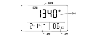
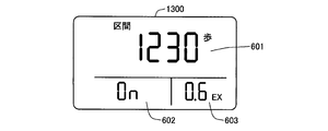
- FIG. 13A is an explanatory diagram of an example of display contents (section measurement) of the pedometer according to the first embodiment of the present invention.
- FIG. 13-2 is an explanatory diagram of an example (section measurement) of display contents of the pedometer according to the first embodiment of the present invention.
- FIG. 13-3 is an explanatory diagram of an example (section measurement) of display contents of the pedometer according to the first embodiment of the present invention.
- FIG. 13-4 is an explanatory diagram of an example (section measurement) of the display contents of the pedometer according to the first embodiment of the present invention.
- FIG. 13-5 is an explanatory diagram of an example (section measurement) of display contents of the pedometer according to the first embodiment of the present invention.
- FIG. 14 is an explanatory diagram showing an example (date) of display contents of the pedometer according to the first embodiment of the present invention.
- FIG. 15 is an explanatory diagram showing an example (memory) of display contents of the pedometer according to the first embodiment of the present invention.
- FIG. 16 is a block diagram showing a functional configuration of the processing device of the pedometer according to the second embodiment of the present invention.
- FIG. 17 is an explanatory diagram (part 1) illustrating the concept of display switching of the pedometer according to the second embodiment of the present invention.
- FIG. 18 is an explanatory diagram (part 2) of the concept of display switching of the pedometer according to the second embodiment of the present invention.
- FIG. 19 is an explanatory view showing an example of the display contents of the pedometer according to the second embodiment of the present invention (“JOG Today Display” screen).
- FIG. 20 is an explanatory diagram showing an example of the display contents of the pedometer according to the second embodiment of the present invention (“JOG section display” screen).
- FIG. 17 is an explanatory diagram (part 1) illustrating the concept of display switching of the pedometer according to the second embodiment of the present invention.
- FIG. 18 is an explanatory diagram (part 2) of the concept of display switching of the pedometer according to the second embodiment of the present invention.
- FIG. 21 is an explanatory diagram showing an example (walking time by jogging) of display contents of the pedometer according to the second embodiment of the present invention.
- FIG. 22 is an explanatory diagram showing an example of the display contents of the pedometer according to the second embodiment of the present invention (“JOG section measurement in progress” screen).
- FIG. 23 is a flowchart showing the steps of the counting control process and the display switching control process of the pedometer according to the second embodiment of the present invention.
- FIG. 1 is a block diagram showing a hardware configuration of a pedometer according to the first embodiment of the present invention.
- the pedometer 100 according to the first embodiment of the present invention is a three-axis acceleration sensor capable of detecting accelerations in three different directions (X-axis direction, Y-axis direction, and Z-axis direction). It has.
- the three-axis acceleration sensor includes an X-axis acceleration sensor 101 that detects acceleration in the X-axis direction, a Y-axis acceleration sensor 102 that detects acceleration in the Y-axis direction, and a Z-axis acceleration sensor that detects acceleration in the Z-axis direction. 103.
- a well-known sensor can be used as the acceleration sensor.
- the X-axis direction, the Y-axis direction, and the Z-axis direction are directions unique to the pedometer 100, and change with changes in the posture (direction and inclination) of the pedometer 100.
- the pedometer 100 determines whether or not the subject is a body motion of a subject carrying the pedometer 100 based on the output signal of the triaxial acceleration sensor, and counts the number of steps by counting the body motion.
- a processing device 104 for counting is provided. The detailed configuration of the processing device 104 will be described later.
- the pedometer 100 includes a display device 105 that displays the body movement counted by the processing device 104.
- the display device 105 includes, for example, a liquid crystal panel and a liquid crystal driving circuit. A detailed configuration of the display device 105 will be described later.
- the pedometer 100 is connected to a time measuring device 106 that measures the current time and various times, an input device 107 as an operation instruction means including various operation switches, and an information processing device (not shown) such as a personal computer.
- An interface (I / F) 108 is provided for transmitting and receiving data measured by the meter 100 and data input to the information processing device between the pedometer 100 and the information processing device.
- the time measuring device 106 includes, for example, an oscillation circuit, and generates a signal having a predetermined frequency serving as a reference for time measuring processing, and a signal processing device for a signal having a predetermined frequency generated from the reference signal generating portion. 104 and a counter for outputting to the display device 105.
- the I / F 108 includes a connection terminal such as a USB, for example, and controls transmission / reception of data by application software installed in the information processing apparatus.
- FIG. 2 is a block diagram showing a functional configuration of the pedometer processing apparatus according to the first embodiment of the present invention.
- the processing device 104 includes an X-axis analog / digital conversion unit 201, a Y-axis analog / digital conversion unit 202, a Z-axis analog / digital conversion unit 203, an acceleration acquisition unit 204, and a cosine peak value detection unit 205.
- a lower chord peak value detection unit 206 a peak difference calculation unit 207 having a function as a calculation unit, a threshold determination unit 208 having a function as a determination unit, a flag control unit 209, a counting unit 210, a storage unit 211, and a count control unit 212. And a calculation unit 213.
- These functional units may be realized by hardware, or may be realized by executing a program with a CPU or the like.
- the X-axis analog / digital conversion unit 201, the Y-axis analog / digital conversion unit 202, and the Z-axis analog / digital conversion unit 203 are respectively connected to the X-axis acceleration sensor 101 and the Y-axis acceleration sensor 102 via input terminals not shown.
- the analog voltage signals output from these sensors are sampled at a predetermined cycle and converted to digital data. It is desirable that the X-axis analog / digital conversion unit 201, the Y-axis analog / digital conversion unit 202, and the Z-axis analog / digital conversion unit 203 sample each sensor output signal at the same timing.
- the acceleration acquisition unit 204 acquires the magnitude of acceleration based on the output values of the analog / digital conversion units 201, 202, and 203 for each axis.
- the magnitude of acceleration is repeatedly increased and decreased.
- the upper string peak value detection unit 205 detects a peak value (referred to as an upper string peak value) when the magnitude of the acceleration acquired by the acceleration acquisition unit 204 switches from an increasing tendency to a decreasing tendency. In order to detect the upper string peak value, the upper string peak value detection unit 205 performs, for example, the following processing.
- the upper string peak value detection unit 205 stores the acceleration value output from the acceleration acquisition unit 204 in a buffer, compares the stored value of the buffer with the acceleration value output from the acceleration acquisition unit 204, and Update the stored value of the buffer with the larger value.
- the upper chord peak value detecting unit 205 sets the stored value of the buffer at that time as the upper chord peak value.
- the lower chord peak value detection unit 206 detects a peak value (referred to as the lower chord peak value) when the magnitude of the acceleration acquired by the acceleration acquisition unit 204 switches from a decreasing tendency to an increasing tendency. In order to detect the lower chord peak value, the lower chord peak value detecting unit 206 performs, for example, the following processing.
- the lower chord peak value detection unit 206 stores the acceleration value output from the acceleration acquisition unit 204 in a buffer, compares the stored value of the buffer with the acceleration value output from the acceleration acquisition unit 204, and Update the stored value of the buffer with the smaller value.
- the lower chord peak value detecting unit 206 sets the stored value of the buffer at that time as the lower chord peak value.
- the peak difference calculation unit 207 calculates the difference between the lower chord peak value detected by the lower chord peak value detection unit 206 and the upper chord peak value detected by the upper chord peak value detection unit 205. At that time, the peak difference calculation unit 207 may calculate the difference between the lower chord peak value and the immediately following upper chord peak value, or may calculate the difference between the upper chord peak value and the immediately following lower chord peak value. .
- the threshold value determination unit 208 compares the difference between the lower chord peak value and the upper chord peak value calculated by the peak difference calculation unit 207 with a preset threshold value, and determines whether body motion is detected based on the result. Determine. For example, the threshold determination unit 208 determines that body movement has been detected when the difference between the lower chord peak value and the upper chord peak value is greater than the threshold.
- the flag control unit 209 turns on the body motion detection flag at a predetermined timing when the threshold determination unit 208 determines that the body motion has been detected.
- the predetermined timing is a timing determined by the magnitude of the acceleration acquired by the acceleration acquisition unit 204.
- the flag control unit 209 switches off the body motion detection flag when a predetermined period has elapsed after turning on the body motion detection flag.
- the counting unit 210 is configured by a counter, always counts the number of times the body motion detection flag is turned on, counts the count value as a plurality of step count data described later, and holds (stores) it in the storage unit 211.
- the step count data is sent to the display device 105 via an output terminal (not shown). In this way, the counting unit 210 counts a plurality of step count data.
- the storage unit 211 stores various data in addition to the count values of the plurality of step count data counted by the counting unit 210. The type of data to be stored will be described later.
- the storage unit 211 realizes its function by, for example, a RAM. In this way, the storage unit 211 stores a plurality of step count data counted by the counting unit 210.
- the plurality of step count data is, for example, step count data counted from different points in time. Specifically, it is cumulative step count data over a plurality of days (for example, see FIG. 12 described later) and step count data obtained by measuring a predetermined section (for example, see FIGS. 13-1 to 13-5 described later). Further, it may be past step count data (see, for example, FIG. 15 described later).
- the counting unit 210 receives a numerical value related to the result calculated by the calculating unit 213, stores the numerical value in the storage unit 211, and sends the numerical data to the display device 105 via an output terminal (not shown).
- the counting control unit 212 controls the counting process by the counting unit 210. Specifically, a start operation means for instructing start of counting of any number of step data (for example, section measurement shown in FIG. 13-1 described later) or a stop operation for instructing stop of counting of step number data.
- the counting unit 210 of the selected step count data controls the start and stop of counting. For example, when the counting unit 210 counts a plurality of step data such as step data, cumulative step data, and section measurement step data for the current day, the step data for the section measurement is the step data for the current day even if the counting is stopped. The counting is continued except for the step count data of the section measurement such as the cumulative step count data.
- the time measuring device 106 as the stop time measuring means measures the time after the stop operation means is instructed to stop counting the step count data. Then, the count control unit 212 serving as a stop time counting unit cancels the stop of counting the step count data when a predetermined time (for example, 1 hour) has elapsed as a result of the time counting by the time counting device 106. As a result, even if the measurement of the step count data is stopped in the section measurement, the measurement of the step count data is automatically resumed when a predetermined time has elapsed, and the carrier forgets to cancel the stop. Even in this case, the section measurement can be continued.
- a predetermined time for example, 1 hour
- the predetermined time is not limited to one hour, and can be arbitrarily set by receiving an input from a user using the input device 107, for example. For example, it may be set in units of 30 minutes or in units of one hour, or may be set in units of minutes or seconds. Accordingly, the counting of the step count data can be automatically restarted in accordance with the reason for temporarily stopping the measurement of the step count data.
- the count control unit 212 also stores in the storage unit 211 the date and time when resetting (starting) of the count is instructed based on the current date and time counted by the clock device 106 as a timekeeping means for measuring the current date and time. . Then, when displaying the section measurement screen, the counting unit 210 sends information about the date and time (all or part of the date and time) stored in the storage unit 211 to the display device 105 together with the step count data in the section measurement. The display device 105 displays the sent date / time data. At that time, all of the date and time (year, month, day, and time) may be displayed. If the reset is instructed on the current day, the time is displayed. If the start of counting is instructed before the previous day, Only the date may be displayed. In this way, by displaying only the minimum necessary information in a limited display area, it is possible to improve the visibility of display contents.
- the calculation unit 213 counts on the body motion detection flag and counts it as the step count data, based on the information related to the time from the time measuring device 106 and the information related to the weight and the stride of the user set in advance.
- a numerical value (step count related data) other than the counted step count data is calculated.
- the step count related data may be calculated based on data other than the step count data, or may be calculated based on data other than the step count data and the step count data.
- the counting unit 210 receives a numerical value related to the result calculated by the calculating unit 213, holds (stores) the numerical data in the storage unit 211, and displays the numerical data via an output terminal (not shown). Send to 105.
- the number of steps-related data is the calorie consumption (for example, see FIG. 7 described later), the fat burning amount (for example, see FIG. 8 to be described later), the walking distance (for example, see FIG. 9 to be described later). , Walking time (for example, see FIG. 10 described later), average speed (for example, see FIG. 11 described later), and the like.
- the step count data and the step count related data may have a plurality of display formats of the same type. Furthermore, the step count data and the step count related data may have the same number of the plurality of display formats.
- the plurality of display formats may be step count data and step count related data in different periods. Details of these step count related data will be described later.
- FIG. 3 is a block diagram showing a functional configuration of the display device of the pedometer according to the first embodiment of the present invention.
- the display device 105 includes a display unit 301 and a switching control unit 302.
- the display unit 301 switches and displays the step count data sent from the counting unit 210 and numerical data different from the step count.
- the display unit 301 realizes its function by, for example, a liquid crystal panel.
- the switching control unit 302 controls the display unit 301 so as to display information on the step count data, and is displayed on the display unit 301 based on a predetermined operation input (switch operation) of the user from the input device 107.
- the display unit 301 is controlled to switch the displayed step count data to numerical data different from the step count.
- the switching control unit 302 causes the display unit 301 to Regardless of what data is displayed, the display unit 301 is controlled to switch to predetermined step count data (for example, the current step count) and display it.
- the switching control unit 302 realizes its function by, for example, a liquid crystal driving circuit.
- FIG. 4A is a flowchart of a pedometer counting control process and a display switching control process according to the first embodiment of the present invention.
- the switching control unit 302 controls the display unit 301 to display a normal screen (“the number of steps of the day”) (step S401).
- a normal screen (“the number of steps of the day”)
- step S402 it is determined whether or not there is an instruction to display the section measurement screen (step S402). Specifically, for example, it is determined whether or not the setting switch 501 shown in FIG. 5 has been continuously pressed twice (when the setting switch 501 is pressed once, the “cumulative data” screen is displayed).
- step S403 If there is no instruction to display the section measurement screen in step S402 (step S402: No), it is next determined whether or not there is an instruction to display another display screen (step S403). If there is an instruction to display another display screen (step S403: Yes), the switching control unit 302 displays the other display screen. On the other hand, when there is no instruction to display another display screen (step S403: No), the switching control unit 302 maintains the “normal screen” in the display unit 301.
- step S402 when there is an instruction to display the section measurement screen in step S402 (step S402: Yes), the switching control unit 302 displays the section measurement screen (see FIG. 13-1) (step S404). Then, the count control unit 212 determines whether or not the current section measurement is being performed on the section measurement screen (step S405). Here, when the section measurement is being performed (step S405: Yes), the process proceeds to step S410.
- step S405 when the section measurement is not being performed (step S405: No), the counting control unit 212 determines whether or not there is a measurement start instruction (step S406). Specifically, the measurement start instruction is determined based on, for example, whether or not an up switch 503 shown in FIG.
- step S406: No when there is no measurement start instruction (step S406: No), the switching control unit 302 determines whether or not 15 seconds have passed without any switch being pressed (step S407). If 15 seconds have not yet elapsed (step S407: No), the switching control unit 302 next determines whether there is an instruction to display another display screen (step S408).
- step S408 when there is an instruction to display another display screen (step S408: Yes), the switching control unit 302 displays the other display screen. On the other hand, if there is no instruction to display another display screen in step S408 (step S408: No), the process returns to step S406, and steps S406 to S408 are repeated until 15 seconds have elapsed. In step S407, if 15 seconds have elapsed (step S407: Yes), the process returns to step S401, and the normal screen is displayed.
- step S406 when there is a measurement start instruction (step S406: Yes), measurement by the counting unit 210 (counting of step count data) is started (step S409).
- “ON” indicating that the measurement is started is displayed in the date and time information display area 602 on the lower left side of the display screen for a predetermined time. After a predetermined time has elapsed, the display is switched to date / time information. Then, the step count data counted by the counting unit 210 is displayed as section measurement data every time it is counted (step S410).
- the counting control unit 212 determines whether there is an instruction to reset the displayed data (step S411). Specifically, the reset instruction is determined based on, for example, whether or not the setting switch 501 is continuously pressed for about 2 seconds (long-pressed) by the carrier. If there is a reset instruction (step S411: Yes), the count control unit 212 resets the counter value of the step count data to 0 (step S412). Accordingly, the display of the step count data display area 601 and the exercise amount information display area 603 on the display screen is both “0” (see FIG. 13-4). Furthermore, the count control unit 212 acquires the reset date and time from the timing device 106 and stores it in the storage unit 211 (step S413). On the other hand, when there is no reset instruction (step S411: No), nothing is done and the process proceeds to step S414.
- the count control unit 212 determines whether or not there is a measurement stop instruction (step S414). Specifically, the measurement stop instruction is determined based on, for example, whether or not the down switch 504 shown in FIG. Here, when there is no measurement stop instruction (step S414: No), the switching control unit 302 determines whether 15 seconds have passed without any switch being pressed (step S415). If 15 seconds have not yet elapsed (step S415: No), the switching control unit 302 next determines whether there is an instruction to display another display screen (step S416).
- step S416 when there is an instruction to display another display screen (step S416: Yes), the switching control unit 302 displays the other display screen. On the other hand, if there is no instruction to display another display screen in step S416 (step S416: No), the process returns to step S411, and steps S411 to S416 are repeated until 15 seconds have elapsed.
- step S415 when 15 seconds have elapsed (step S415: Yes), the process returns to step S401, and the normal screen is displayed.
- step S414 when there is a measurement stop instruction in step S414 (step S414: Yes), the counting control unit 212 stops the measurement (counting of step count data) by the counting unit 210 (step S417).
- “OFF” indicating that the measurement is stopped is displayed in the date and time information display area 602 on the lower left side of the display screen for a predetermined time. After a predetermined time has elapsed, the display is switched to date / time information. Then, the step count data counted by the counting unit 210 and stopped counting is displayed as section measurement data. Thereafter, the process proceeds to step S406.
- FIG. 4-2 is a flowchart of another procedure of the pedometer counting control process according to the first embodiment of the present invention.
- FIG. 4B only the processing procedure of the count control unit 212 is described, and therefore, the display switching processing procedure of the switching control unit 302 is omitted.
- the count control unit 212 determines whether or not there is a measurement start instruction (step S451). Specifically, the measurement start instruction is determined based on, for example, whether or not an up switch 503 shown in FIG. Here, when there is a measurement start instruction (step S451: Yes), the counting control unit 212 starts measurement (counting of step count data) by the counting unit 210 (step S452).
- the count control unit 212 determines whether there is an instruction to reset the displayed step count data (step S453). Specifically, the reset instruction is determined based on, for example, whether or not the setting switch 501 is continuously pressed for about 2 seconds (long-pressed) by the carrier.
- the count control unit 212 resets the count of the step count data and sets the display value to 0 (step S454). Further, the count control unit 212 acquires the reset date and time from the timing device 106 and stores it in the storage unit 211 (step S455).
- step S453: No nothing is done and the process proceeds to step S456.
- the counting control unit 212 determines whether or not there is a measurement stop instruction (step S456). Specifically, the measurement stop instruction is determined based on, for example, whether or not the down switch 504 shown in FIG. If there is no measurement stop instruction (step S456: No), the process returns to step S453. Thereafter, steps S453 to S456 are repeated.
- step S456 when there is a measurement stop instruction (step S456: Yes), the counting control unit 212 stops the measurement (counting of step count data) by the counting unit 210 (step S457).
- a predetermined time for example, 1 hour
- step S458: No If the predetermined time has not elapsed (step S458: No), it is determined whether or not a measurement start instruction similar to that in step S451 has been issued (step S459).
- step S459 when there is a measurement start instruction (step S459: Yes), the process returns to step S452, and the measurement is resumed. On the other hand, when there is no measurement start instruction in step S459 (step S459: No), the process returns to step S458. Thereafter, steps S458 and S459 are repeated.
- step S458 when a predetermined time has elapsed (step S458: Yes), the process returns to step S452, and measurement is resumed. By doing in this way, counting of step count data can be automatically restarted after a predetermined time has elapsed.
- the reset instruction is a procedure that can be performed only after the measurement start instruction is issued, but is not limited to this, and the measurement start instruction is not limited to this.
- a reset instruction may be issued before performing. Further, the date / time information when the measurement start instruction is issued may be stored together. Further, the reset instruction may be performed in a state where the counting is stopped after the counting stop instruction. In this case, the state where the counting is stopped may be maintained even after the reset instruction, or the reset instruction may be used as a measurement start instruction and measurement may be started by the reset instruction.
- the step count data of the section measurement counted between the previous reset (or measurement start) instruction and the current reset instruction may be stored. Also, in accordance with the storage of the step count data for the section measurement, either or both of the date / time information for starting the measurement of the step count data for the stored section measurement and the date / time information for completing the count by performing the reset instruction are stored. Also good.
- FIG. 5 is an explanatory diagram showing the appearance of the pedometer according to the first embodiment of the present invention.
- a pedometer 100 includes a display unit (display screen) 301, a setting switch 501 for switching a display format (normal display ⁇ cumulative data display ⁇ section measurement display ⁇ date / time display), and data other than step count data (step count ⁇
- a changeover switch 502 for switching to display calorie consumption ⁇ amount of fat burnt ⁇ walking distance ⁇ walking time ⁇ average speed
- an up switch 503 and a down switch 504 for switching to display past data.
- the switches are also used for setting a stride, setting a target step count, setting a date and time, starting and ending (stopping) section measurement, resetting section measurement, and the like.
- FIG. 6A is an explanatory diagram illustrating an example of a normal screen (today's step count display screen).
- a normal screen (“step count display” screen) 600 in FIG. 6A includes a step count data display area 601, a date / time information display area 602, an exercise amount information display area 603, and a target achievement information display area 604.
- the step count data display area 601 displays step count data.
- “12441 (steps)” indicates the number of steps of today. Whether or not it is today's step count display can be easily determined by the carrier by whether or not there is a display of “today” in the date information display area 602 on the lower left side of the “step count display” screen 600.
- “15:24” in the date / time information display area 602 indicates the current time.
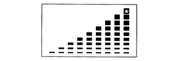
- FIG. 6B is an explanatory diagram of a change in display of the goal achievement level information.
- FIG. 6B shows a state (9 steps) in which the target achievement level increases as the leftmost display is shifted to the right display.
- the number of rectangular marks is increased and increased as the target achievement level increases.
- the vertical width of the rectangular mark gradually increases.
- the number of rectangular marks is maximized, and a star is displayed on the top mark (see the rightmost display in FIG. 6-2). This makes it possible for the wearer to easily recognize the target achievement level at a glance.
- the screen returns to the normal screen 600 shown in FIG.
- the calorie consumption, the fat burning amount, the walking distance, the walking time, and the average speed are calculated by the calculation unit 213 based on “12441 (steps)” that is today's step count data of the carrier shown in FIG. The number of steps related data.
- the display format is switched to the “cumulative data” screen 1200 shown in FIG. In FIG. 12, “58765 (steps)”, which is the accumulated data for seven days (from 6 days ago to today), is displayed. Whether or not it is the “cumulative data” screen 1200 is determined by the mobile phone easily based on whether or not there is a display of “cumulative” on the upper left side of the screen and “2-08 to today” on the lower left side. It is possible for the user to easily determine that the accumulated data from the display of “2-08 to today” is from February 8 to today.
- the target step count achievement degree displays the total number of steps for 7 days with respect to “daily target step count ⁇ 7” in 9 stages. Further, every time the changeover switch 502 is pressed, the cumulative data in the other data is displayed as in the “step count display” screen 600.
- the time “10: 43 ⁇ ” is displayed in the date / time information display area 602, whereas in FIG. 13-2, the date “2-14 ⁇ ” is displayed. This is to display the date instead of the time when the section measurement is over two days.
- the start time “hh: mm (hour: minute))” is displayed on the day when the section measurement is reset, and the start date “MM-DD (month-day)” is displayed after the next day after the section measurement is reset. To do.
- the date and time (date and time) of the measurement start instruction may be stored and displayed. Further, the reset date and the reset time may be switched and displayed at a predetermined timing (for example, alternately every predetermined time (for example, 1 second) or in response to pressing of a predetermined switch). Further, the date and time may be displayed simultaneously instead of the illustrated display.
- the up switch 503 When the up switch 503 is continuously pressed for about 2 seconds (long pressing) in the state of the “section measurement” screen 1300 in FIG. 13-1 (or FIG. 13-2), as shown in FIG.
- the display in the information display area 602 is switched to “ON” display. Thereby, it can be shown that the section measurement is performed.
- the setting switch 501 is continuously pressed for about 2 seconds, as shown in FIG. 13-4, the step count data for the section measurement is reset, the step count data for the section measurement becomes 0, and the section measurement is started.
- the exercise amount information display area 603 is also displayed as “0.0 (EX)”.
- the down switch 504 when the down switch 504 is continuously pressed for about 2 seconds (long pressing), as shown in FIG. 13-5, the display of the date / time information display area 602 is switched to “OFF” display. This can indicate that the section measurement has been stopped (terminated). Then, when the up switch 503 is continuously pressed for about 2 seconds, the section measurement is resumed. By repeatedly pressing and holding the up switch 503 and the down switch 504 without resetting, it is possible to repeatedly measure and stop the interval measurement. As described above, the ON / OFF of the section measurement can be utilized when, for example, it is not desired to enter the number of steps after entering the inn in the section measurement due to overnight hiking.
- any plurality of sections may be measured.
- illustration is omitted, on the “section measurement” screen 1300, a number or a symbol indicating the section may be displayed so that the user can understand which section it is.
- the present invention may be realized by continuously counting the step count data in another section measurement.
- the normal screen 600 shown in FIG. 6A Each time the setting switch 501 is pressed, the normal screen 600 shown in FIG. 6A ⁇ the “cumulative data” screen 1200 shown in FIG. 12 ⁇ the “total data” screen shown in FIG. 13-1 (or FIG. 13-2).
- a “memory (step count display one day ago)” screen 1500 is displayed. Switch to For example, if today is February 15, “2-14 M” will be displayed in the lower left of the “Memory (steps displayed one day ago)” screen 1500, so it is easy for the mobile phone to display the memory display. I can understand.
- the display format is “2 days ago” ⁇ “3 days ago” ⁇ ... ⁇ “29 days ago” ⁇ “30 days ago” ⁇ “today” Switches.
- the display format is switched from “30 days ago” ⁇ “29 days ago” ⁇ ... ⁇ “2 days ago” ⁇ “today”.
- the memory is for 30 days, but is not limited to this number of days, and may be shorter than 30 days or longer than 30 days.
- each of these screens 700 to 1400 and screens not shown
- the display is displayed on “Today” on each screen after 15 seconds.
- the screen is switched to the normal screen 600 shown in FIG. That is, even if the “walking distance” screen 900 of “4 days ago” is displayed, if there is no operation instruction, it does not switch to the “walking distance” screen 900 of 15 seconds later, but instead of FIG. 1 is switched to the normal screen 600 shown in FIG.
- the counting unit 210 that counts a plurality of step count data
- the storage unit 211 that stores the plurality of step count data counted by the counting unit 210
- the storage unit 211 respectively. Since the display device 105 for displaying the stored step count data and the input device 107 for instructing the stop of the count of the step count data are provided, it is possible to freely stop counting the arbitrary step count data at the intention of the wearer. it can.
- the counting control unit 212 for canceling the stop of the counting of the step count data is provided, when it is not desired to count the number of steps during the section measurement, the counting of the number of steps is temporarily interrupted only during that time, and then the counting is resumed. It is possible to accurately measure the step count data of the section to be measured.
- the time counting device 106 that measures the time since the stop is instructed is provided, and the count control unit 212 cancels the stop of counting the number of steps when a predetermined time has passed as a result of the time counting by the time measuring device 106. Therefore, even when it is forgotten to return to ON, desired measurement can be performed.
- the input device 107 for setting a predetermined time is provided, it is possible to realize automatic return according to the stop state.
- the counting of the number of steps can be interrupted.
- FIG. 16 is a block diagram showing a functional configuration of the processing device of the pedometer according to the second embodiment of the present invention.
- the processing device 104 of the pedometer 100 includes an X-axis analog / digital conversion unit 201, a Y-axis analog / digital conversion unit 202, and a Z-axis analog / digital conversion unit. 203, acceleration acquisition unit 204, upper chord peak value detection unit 205 and lower chord peak value detection unit 206, peak difference calculation unit 207 having a function as a calculation unit, threshold determination unit 208 having a function as a determination unit, flag control unit 209 A counting unit 210, a storage unit 211, a counting control unit 212, and a calculation unit 213. These functional units may be realized by hardware, or may be realized by executing a program with a CPU or the like.
- the counting unit 210 included in the processing apparatus 104 always counts body movements as in the first embodiment, counts the count value as a plurality of step count data described later, and stores (stores) the count value in the storage unit 211.
- the plurality of step count data includes step count data counted from different points in time, step count data by walking that satisfies a specific condition, and the like. Specifically, the number of steps of the day by normal walking, the total number of steps over a plurality of days, the number of steps measured for a predetermined section, the number of steps by jogging to be described later, the total number of steps over a plurality of days, a predetermined section The number of steps measured. Further, it may be the number of steps in the past due to normal walking or the number of steps in the past due to jogging.
- the count control unit 212 included in the processing device 104 receives an operation instruction from the input device 107 serving as a section designation receiving unit that receives designation of an arbitrary section, and controls the counting processing by the counting section 210 in the designated section. Specifically, for example, the count control unit 212 counts the step count data in the specified arbitrary section of the step count data counted by the count section 210 separately from the outside of the section. The counting process by the counting unit 210 is controlled.
- the storage unit 211 included in the processing device 104 stores the step count data counted in a specified arbitrary section among the step count data counted by the counting section 210 for each arbitrary section.
- the storage unit 211 stores, for example, information indicating the step count data counted in a specified arbitrary section and information indicating the start date / time and end date / time of the arbitrary section in association with each other.
- the start date and time of an arbitrary section is specified as “January 10, 2010 17:30”, and the end date and time of an arbitrary section is set to “January 10, 2010 18 For example, “30 hours”.
- the length of an arbitrary section is 1 hour.
- the storage unit 211 includes, for example, information indicating the step count data counted in the specified arbitrary section, and information indicating the start date and time and the time from the start to the end of the arbitrary section. Are stored in association with each other.
- the start date and time of an arbitrary section is specified as “January 10, 2010 17:30”, and the time from the start to the end is specified as “1 hour”. can do.
- the end date and time of an arbitrary section is set to “January 10, 2010, 18:30”.
- An arbitrary section is a period (time) from the start of an arbitrary section specified by receiving an operation instruction from the input device 107 to the end of the arbitrary section specified by receiving an operation instruction from the input device 107. ).
- the start date and time of an arbitrary section is the date and time when an operation for specifying the start of an arbitrary section is accepted
- the end date and time of an arbitrary section is the date and time when an operation for specifying the end of an arbitrary section is received
- the length (time) of the section changes appropriately.
- the lap time of the predetermined course can be stored by setting one section from the start of walking on the predetermined course until the carrier makes one turn of the predetermined course.
- the storage unit 211 stores the number-of-steps data counted by the counting unit 210 for each arbitrary section that has been designated by an operation instruction in the input device 107. Specifically, for example, when a carrier goes around a predetermined course for a plurality of laps, if the start and end of a section are specified for each lap, a plurality of lap times per lap of the predetermined course are stored. be able to.
- the counting control unit 212 controls the counting process by the counting unit 210 so as to count the number of steps by walking that satisfies a specific condition as the step count data.
- walking that satisfies a specific condition means, for example, that the number of body movements counted in a predetermined time is equal to or greater than a predetermined number, and the body movements counted are more than a predetermined strength, that is, during normal walking. It can be “jogging” that counts body movements that can be determined to be stronger. When jogging, the strength of body movement that occurs when kicking or landing on the ground is stronger than during normal walking. When the motion detection is detected, the body motion detection flag is turned on, and the counting process by the counting unit 210 is controlled so that the body motion is counted as jogging step count data.
- the count control unit 212 counts the number of body movements counted in a predetermined time based on the accelerations detected by the X-axis acceleration sensor 101, the Y-axis acceleration sensor 102, and the Z-axis acceleration sensor 103 to a predetermined number or more.
- the counting process by the counting unit 210 is controlled so as to count the number of body movements that can be determined to be greater than a predetermined strength, that is, stronger than that during normal walking, as jogging step count data.
- the jogging step count data is a body that can be determined that the number of body movements counted in a predetermined time is greater than or equal to a predetermined number, such as so-called rapid walking walking at a higher speed than normal walking instead of jogging. Movement may be counted.
- walking fast walking fast
- the interval of body movements that occur during fast walking is shorter than the interval during normal walking.
- the body motion detection flag is turned on, and the counting process by the counting unit 210 is controlled so as to count the body motion.
- the counting control unit 212 counts body movements that can be determined as walking fast based on the accelerations detected by the X-axis acceleration sensor 101, the Y-axis acceleration sensor 102, and the Z-axis acceleration sensor 103. Thus, the counting process by the counting unit 210 is controlled. Moreover, you may count the body movement of both jogging and rapid walking.
- the walking speed may be calculated based on the step length of the carrier, the number of steps per predetermined time, and the body movement when the calculated walking speed is equal to or higher than the predetermined speed may be counted as the step count data.
- the count control unit 212 performs counting processing of jogging step count data only when there is a body motion determined to be a body motion by jogging in accordance with the above various determination criteria. The counting process by the counting unit 210 is controlled.
- step count data counted as body movements due to jogging or fast walking can be accumulated and counted in the “normal walking mode”.
- the number of steps counted as a body movement by jogging is also counted as the number of steps by a normal step. More specifically, for example, in the case of 1000 steps, when 500 steps are taken for normal steps and 500 steps are taken for jogging, the step count data for jogging is 500 (steps), and the step count data for normal steps is 1000 (steps).
- the step count data counted as the body movement by jogging may be counted only for the jogging step count data.
- step count data is acquired separately for jogging and normal walking. More specifically, for example, in the case of 1000 steps, when the number of steps in the normal step is counted as 500 steps and the number of steps in the jogging is counted as 500 steps, the number of steps in jogging is 500 (steps), and the number of steps in the normal step is 500 (steps).
- the count control unit 212 counts a plurality of step count data based on the number of steps by walking, and further receives an operation instruction from the input device 107 and receives an operation instruction from the input device 107, and further receives an operation instruction from the input device 107.
- the counting process by the counting unit 210 is controlled so as to count the step count data based on the number of steps by walking satisfying a specific condition in an arbitrary section in which the designation is received.
- the count control unit 212 counts the number of steps counted as the body movement by the normal step and jogging, and any section for which the designation is accepted
- the counting process by the counting unit 210 is controlled so that the number of steps counted as the body movement by jogging is counted as the number of steps data for jogging section measurement.
- the counting control unit 212 controls the counting process by the counting unit 210.
- an operation instruction is received from the input device 107 serving as a section designation receiving unit that indicates an arbitrary section for counting any one of a plurality of step data (for example, jogging section measurement step data).
- the counting unit 210 controls the start and stop of the received step count data. For example, when the counting unit 210 counts a plurality of step count data such as step count data, cumulative step count data, jogging step count data, jogging section count step count data on the current day, the jogging section count step count data stops counting. However, counting is continued except for the step count data of the jogging section measurement.
- the calculation unit 213 counts the body motion detection flag on, and counts the number of steps counted as the step count data by the counting unit 210, information on the time from the time measuring device 106, and information on the weight of the user who is set in advance, information on the step length, and the like. Based on this, a numerical value (step count related data) other than the counted step count data is calculated.
- the step count related data may be calculated based on data other than the step count data. Alternatively, the step count related data may be calculated based on the step count data and data other than the step count data.
- the counting unit 210 Since the counting unit 210 counts the jogging step count data as the body motion due to jogging, the calculating unit 213 can calculate the jogging step count related data based on the jogging step count data. Then, the counting unit 210 receives a numerical value related to the result calculated by the calculating unit 213 and holds (stores) the step count related data obtained by jogging in the storage unit 211. Further, the counting unit 210 sends the step count related data by jogging calculated by the calculating unit 213 to the display device 105 via an output terminal (not shown). Thereby, the display part 301 can display the step count related data by jogging.
- the calculation unit 213 calculates step count related data by jogging section measurement based on the jogging section measurement step count data counted for each arbitrary section specified by the counting section 210 under the setting of “jogging mode”. be able to. Then, the counting unit 210 transmits the step count related data obtained by the jogging section measurement calculated by the calculation unit 213 to the display device 105 via an output terminal (not shown). Thereby, the display part 301 can display the step count related data by the jogging section measurement measured under the setting of the “jogging mode” for each arbitrary section.
- the display device 105 provided in the pedometer according to the second embodiment of the present invention displays step count data based on the number of steps by walking that satisfies a specific condition on the display unit 301. Specifically, the display device 105 displays, on the display unit 301, step count data counted as body movements due to jogging under the setting of “jogging mode” based on an operation instruction from the input device 107.
- the display device 105 displays step count related data based on the body movement by jogging under the setting of the “jogging mode”. May be displayed. Thereby, the wearer can check the step count data and the step count related data counted as the body movement by jogging.
- the display device 105 is set in the “jogging mode” and within the time corresponding to an arbitrary section, in addition to the jogging section measurement step count data counted as the body movement by jogging, or the jogging section You may display the measurement related step count data. Further, in addition to the step count data and the step count related data, information indicating that body motion is being measured or displayed in the “jogging mode” may be displayed on the display unit 301.
- the information indicating that the body motion due to jogging is being measured or displayed can be, for example, an image or icon of a person running.
- the carrier can check the step count data and the step count related data counted as the body movement by jogging while the “jogging mode” is set. Further, it can be easily recognized that the currently displayed step count data and step count related data are due to jogging.
- FIG. 17 is an explanatory view showing the concept of display switching of the pedometer according to the second embodiment of the present invention.
- FIG. 17 shows a concept of display switching in the display unit 301 and a concept of operation for realizing the display switching.
- the display device 105 starts the “setting mode” and displays the “setting mode” screen.
- the display device 105 When each setting is completed on the “setting mode” screen, the display device 105 starts the “daily display mode” and switches from the “setting mode” screen to the normal screen (“today display” screen) that displays the number of steps of the day. To display. On the normal screen, the number of steps on the corresponding date is displayed. The normal screen is also displayed when the pedometer 100 is activated.
- the display device 105 presses the pressed switches 503 and 504 and the switches 503 and 504. Based on the number of times the button is continuously pressed, the number of steps before a predetermined number of days from one day ago to 30 days ago is displayed. For example, when the up switch 503 is pressed once while the “today display” screen is displayed, the display is switched to the number of steps one day before the current date, and the up switch 503 is pressed twice in succession. Switches to the number of steps 2 days before the current date.
- the display is switched to the number of steps 30 days before the current date, and the down switch 504 is pressed twice in succession. Switches to and displays the number of steps 29 days before the current date.
- the display device 105 displays the “today display” screen, “cumulative data (cumulative display) based on the number of times the setting switch 501 is continuously pressed. ) ”Screen,“ Section measurement (section display) ”screen, and“ Date display ”screen,“ Today display ”screen ⁇ “ Total display ”screen ⁇ “ Section display ”screen ⁇ “ Date and time display ”screen ⁇ “ Switch to display in the order of “display today” screen,.
- “Date display mode” is activated and the “Today display” screen is switched to the “Date display” screen.
- the “setting mode” can be activated when the setting switch 501 is pressed for a long time (for example, about 2 seconds) while the “date and time display” screen is displayed.
- the display device 105 activates the “section display mode” and switches the display to the “section display” screen until the predetermined time (for example, 15 seconds) elapses until the up switch 503 is pressed (for example, 2 seconds).
- the counting unit 210 starts counting (counting step count data), and the step count data counted by the counting unit 210 is displayed as section measurement data each time it is counted.
- the display device 105 is displayed when the setting switch 501 is pressed for a long time (for example, about 2 seconds) after the display is switched to the “section display” screen until a predetermined time (for example, 15 seconds) elapses. Reset the section measurement data.
- the display device 105 displays another display screen after a predetermined time (for example, 15 seconds) elapses after switching to the display of each display screen of the “cumulative display” screen, the “section display” screen, and the “date and time display” screen. If there is no display instruction, the display is automatically switched to the “today display” screen (auto return function). Further, the display device 105 does not perform the above-described auto-return when the changeover switch 502 is pressed for a long time (for example, about 2 seconds) during display of an arbitrary display screen, and thereafter, the switches 501 to 504 are short-pressed. The display screen is not switched even when (for example, within 1 second) (screen HOLD function). When the screen HOLD function is set, the screen HOLD function can be canceled when any one of the switches 501 to 504 is pressed (for example, about 2 seconds).
- a predetermined time for example, 15 seconds
- the display device 105 When the setting switch 501 is pressed for a long time (for example, about 2 seconds) while the “display today” screen is displayed, the display device 105 starts the “display daily JOG mode” and displays the “display today” screen in the jog mode. The screen is switched to the “today display” screen (“JOG today display” screen) (see FIG. 19).
- the “JOG Today Display” screen displays the number of steps counted as body movements due to jogging on today, that is, the current date.
- the display device 105 counts the pressed switches 503 and 504 and the number of times the switches 503 and 504 are continuously pressed. Based on this, the number of steps counted as the body movement by jogging a predetermined number of days before 1 day to 30 days before is displayed. For example, when the up switch 503 is pressed once while the “JOG Today Display” screen is displayed, the number of steps counted as the body movement by jogging is switched to the number of steps one day before the current date. Further, for example, when the up switch 503 is continuously pressed twice while the “JOG Today Display” screen is displayed, the number of steps counted as body movements due to jogging is set to the number of steps two days before the current date. Switch to display.
- the display device 105 when the down switch 504 is pressed once while the “JOG Today Display” screen is displayed, the display device 105 is 30 days before the current date out of the number of steps counted as body movement by jogging. Switch to the number of steps and display. Similarly, for example, when the down switch 504 is continuously pressed twice while the “JOG Today Display” screen is displayed, the display device 105 displays the current date out of the steps counted as body movements due to jogging. Switch to the number of steps 29 days ago.
- the display device 105 displays the “JOG Today Display” screen in the jogging mode based on the number of times the setting switch 501 is pressed.
- Display screens for "Total Display” screen (“JOG Cumulative Display” screen), "Section Display” screen in Jogging Mode ("JOG Section Display” screen) and “Date Display” screen in Jogging Mode (“JOG Date Display” screen) are switched in the order of “JOG today display” screen ⁇ “JOG cumulative display” screen ⁇ “JOG section display” screen ⁇ “JOG date display” screen ⁇ “JOG today display” screen,.
- the “JOG Cumulative Display Mode” is activated, and the “JOG Cumulative Display” screen is switched to display.
- the “JOG section display mode” is activated, and the “JOG section display” screen is switched and displayed. (See FIG. 20).
- the number of steps based on the body movement counted as being due to jogging is displayed in the previous section.
- the “JOG Date Display Mode” is activated, and the “JOG Today Display” screen is displayed as “JOG Date Display”. Switch to the screen.
- the “JOG date / time display mode” the display mode under the setting of the jogging mode can be set.
- the display switch 105 When the up switch 503 or the down switch 504 is pressed during a predetermined time period (for example, 15 seconds) after the display device 105 switches the display to the “JOG section display” screen, the display switch 105 is pressed. 504 and the number of steps counted based on the body movement counted as being caused by jogging based on the number of times the switches 503 and 504 are continuously pressed, the predetermined number of times between 2 times before and 30 times before The number of steps counted in the previous section is displayed.
- a predetermined time period for example, 15 seconds
- the up switch 503 when the up switch 503 is pressed once while the “JOG section display” screen is displayed, the number of steps based on the body movement counted as a result of jogging is switched to the number of steps counted in the previous section. indicate.
- the up switch 503 when the up switch 503 is continuously pressed twice during the display of the “JOG section display” screen, the number of steps based on body movement counted as a result of jogging is the section three times before. Switch to the counted number of steps and display.
- the down switch 504 when the down switch 504 is pressed once while the “JOG section display” screen is displayed, the number of steps counted in the section 30 times before of the number of steps based on the body movement counted as being caused by jogging. Switch to display.
- the down switch 504 when the down switch 504 is continuously pressed twice while the “JOG section display” screen is displayed, the number of steps based on body movement counted as being caused by jogging is counted in the section 29 times before. Switch to the number of steps and display.
- the display device 105 can be used for a period of time after a predetermined time (for example, 15 seconds) elapses after switching to display of each display screen of the “JOG cumulative display” screen, the “JOG section display” screen, and the “JOG date display” screen. If there is no instruction to display the display screen, the display automatically switches to the “JOG Today Display” screen (auto-return function in jogging mode). The display device 105 does not perform the auto return in the jogging mode when the changeover switch 502 is pressed for a long time (for example, about 2 seconds) during display of an arbitrary display screen, and thereafter, the switches 501 to 504 are not performed.
- a predetermined time for example, 15 seconds
- the display screen is not switched even when is pressed for a short time (for example, within 1 second) (screen HOLD function in jogging mode).
- screen HOLD function in jogging mode When the screen HOLD function in the jogging mode is set, the screen HOLD function in the jogging mode can be canceled when any one of the switches 501 to 504 is pressed for a long time (for example, about 2 seconds).
- the pedometer 100 counts the number of steps by jogging in an arbitrary section “JOG The “section measurement” mode is activated, and the “JOG section measurement in progress” screen is displayed (see FIG. 21).
- the user can easily activate the “JOG section measurement” mode by long-pressing the setting switch 501 during the previous display of the “JOG section display” screen, and count the step count data by jogging. It is possible to measure the time of the section where the counting is performed.
- the pedometer 100 measures the number of steps by the counting unit 210 based on the body movement by jogging (counting the number of step data by jogging and measuring the number of steps by jogging) while the “JOG section measurement” mode is activated.
- the display device 105 updates and displays the number of steps by jogging counted by the counting unit 210 every time the number of steps is counted.
- the display device 105 disables the auto-return function while the “JOG section measurement” mode is activated. That is, the display device 105 does not switch the display screen even when a predetermined time (for example, 15 seconds) elapses without operating any of the switches 501 to 504 while the “JOG section measurement” mode is activated.
- the number of steps by jogging counted by the counting unit 210 is updated and displayed every time the number of steps is counted. As described above, the display device 105 does not switch the display screen even when the switches 501, 503, and 504 are pressed for a short time (for example, within one second) while the “JOG section measurement” mode is activated.
- the display is switched in the order of “number of steps” ⁇ “(consumed calories)” ⁇ “amount of burning fat” ⁇ “walking distance” ⁇ “walking speed” ⁇ “number of steps”.
- the display device 105 does not switch the display screen until the switch 501 is pressed for a long time while the “JOG section measurement” mode is activated, but displays the “JOG section measurement in progress” screen.
- a predetermined time limit for example, 10 hours
- the pedometer 100 starts “JOG section measurement” when the setting switch 501 is pressed and held again after the “JOG section measurement” mode is activated by long pressing the setting switch 501 (for example, about 2 seconds). Release the mode.
- a period from when the setting switch 501 is pressed for a long time to start the “JOG section measurement” mode until the setting switch 501 is pressed for a long time is an arbitrary section.
- FIG. 18 is an explanatory diagram showing the concept of display switching of the pedometer according to the second embodiment of the present invention.
- FIG. 18 shows a concept of display switching in the display unit 301 and a concept of operation for realizing the display switching.
- the display device 105 displays information to be displayed on each display screen every time the changeover switch 502 is pressed under the settings of the various display modes described above: “step count” ⁇ “(consumed) calories” ⁇ “ The display is switched in the order of “burning fat amount” ⁇ “walking distance” ⁇ “walking time” ⁇ “walking speed” ⁇ “number of steps”,.
- the walking time on the “JOG section display” screen displayed during the start of the JOG section display mode can be the time from the start of measurement (measurement) in the jogging mode to the end (measurement time). Further, the walking speed on the “JOG section display” screen displayed during the activation of the JOG section display mode is calculated from the time from the start of measurement (measurement) in the jogging mode to the end. In addition, the walking speed may be calculated from the time when the walking speed becomes a predetermined walking speed or more in the section in which the measurement (measurement) is performed in the jogging mode, that is, the measurement time during which the body movement is measured by jogging.
- the walking speed on the “JOG section measurement in progress” screen displayed during the start of the JOG section measurement mode can be calculated from the time after starting the measurement (measurement) in the jogging mode. Further, it may be calculated from the time when the walking speed is higher than a predetermined value in the current section in which the measurement (measurement) is performed in the jogging mode, that is, the measurement time during which the body movement is measured by jogging.
- the walking time which is the elapsed time since the start of the measurement of body movement due to jogging
- the display unit regardless of whether the changeover switch 502 is pressed or the number of times the changeover switch 502 is pressed. It may be always displayed on 301 (see FIG. 21).
- the elapsed time of the jogging mode currently being measured can be quickly confirmed at an arbitrary timing desired by the wearer.
- FIG. 19 is an explanatory diagram showing an example of the display contents of the pedometer according to the second embodiment of the present invention (“JOG Today Display” screen).
- a “JOG Today Display” screen 1900 displays a mark 1901 indicating that the result is measured as jogging.
- a mark 1902 indicating that the number of steps is counted is displayed.
- the “JOG Today Display” screen 1900 indicates that the number of steps counted based on the body movement by jogging is displayed by marks 1901 and 1902.
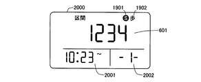
- FIG. 20 is an explanatory diagram showing an example of the display contents of the pedometer according to the second embodiment of the present invention (“JOG section display” screen).
- the “JOG section display” screen 2000 displays the number of steps counted based on the body movement by jogging in an arbitrary section designated by the carrier in addition to the marks 1901 and 1902.
- the “JOG section display” screen 2000 shown in FIG. 20 indicates that the number of steps counted in the previous section is “1234”.
- the start time of the section displaying the number of steps is displayed in the section start time display area 2001 on the lower left side of the display screen.
- the section specifying information display area 2002 on the lower right side of the display screen shows how many steps the displayed step is based on. Yes.
- the “JOG section display” screen 2000 shown in FIG. 20 it is shown that measurement of the previous section is started from 10:23.
- the number of steps in the section from 1 to 30 times before can be displayed.
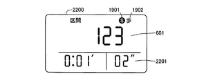
- FIG. 21 is an explanatory diagram showing an example of display contents of the pedometer according to the second embodiment of the present invention (walking time display in “JOG section display”).
- the display screen 2100 displays an elapsed time from when the “JOG section measurement” mode in the section measurement before the selected number of times is activated to the cancellation in the elapsed time display area 2101 on the upper side of the display screen. It is displayed. In the screen 2100 shown in FIG. 21, it is shown that the measurement of the previous section is started from 10:23.
- FIG. 22 is an explanatory diagram showing an example of the display contents of the pedometer according to the second embodiment of the present invention (“JOG section measurement in progress” screen).
- the “JOG interval measurement” screen 2200 includes an elapsed time since the “JOG interval measurement” mode is activated in the elapsed time display area 2201 on the lower side of the display screen in addition to the marks 1901 and 1902. Is displayed.
- FIG. 22 shows that “1 minute 2 seconds” have elapsed since the “JOG interval measurement” mode was activated.
- FIG. 23 is a flowchart showing the steps of the counting control process and the display switching control process of the pedometer according to the second embodiment of the present invention.
- the switching control unit 302 first controls the display unit 301 to display the “today display” screen (step S2301).
- step S2302 it is determined whether or not there is an instruction to set the JOG mode (step S2302).
- step S2302 it is determined whether or not the setting switch 501 has been pressed for a long time (for example, about 2 seconds) while the “Today display” screen is displayed, and the setting switch 501 is pressed for a long time while the “Today display” screen is displayed. If it is determined that there has been an instruction to set the JOG mode. In step S2302, if there is no instruction to set the JOG mode (step S2302: No), the process proceeds to step S2315.
- step S2302 If there is an instruction to set the JOG mode in step S2302 (step S2302: Yes), the switching control unit 302 controls the display unit 301 to display the “JOG today display” screen 1900 (step S2303). ). Then, during the display of the “JOG Today Display” screen 1900, it is determined whether or not there is an instruction to set the “JOG section measurement” mode (step S2304).
- step S2304 it is determined whether or not the setting switch 501 has been pressed for a long time (for example, about 2 seconds) during the display of the previous “JOG section display” screen 2000, and the previous “JOG section display” screen is displayed.
- a long time for example, about 2 seconds
- the setting switch 501 is pressed for a long time during the display of 2000, it is determined that there is an instruction to set the “JOG section measurement” mode.
- step S2304 if there is no instruction to set the “JOG interval measurement” mode (step S2304: No), the process proceeds to step S2312.
- step S2304 when there is an instruction to set the “JOG section measurement” mode (step S2304: Yes), the switching control section 302 displays the “JOG section measurement in progress” screen 2100 on the display section 301. Control is performed (step S2305) and measurement by the counting unit 210 is started (step S2306), and the count control unit 212 starts counting step count data resulting from body movement due to jogging.
- the count control unit 212 calculates various step count related data, and stores the measured step count data and the calculated various step count related data (step S2307).
- the switching control unit 302 controls the display unit 301 to display the JOG section measurement data based on the step count data counted in step S2306 (step S2308).
- step S2309 it is determined whether or not there is an instruction to cancel the setting of the “JOG section measurement” mode.
- step S2309 it is determined whether or not the setting switch 501 has been pressed for a long time (for example, about 2 seconds) while counting the number of steps data due to body movement due to jogging (while the JOG section measurement mode is activated). If the setting switch 501 is pressed for a long time during the mode activation, it is determined that there is an instruction to cancel the setting of the “JOG section measurement” mode.
- step S2309 when there is no instruction for canceling the setting of “JOG section measurement” mode (step S2309: No), counting of step count data due to body movement in jogging and calculation of various step count related data based on the counted step count data.
- the JOG section measurement data is continuously displayed based on the counted step count data.
- step S2309 if there is an instruction to cancel the setting of the “JOG section measurement” mode in step S2309 (step S2309: Yes), the counting control unit 212 stops counting the step count data (step S2310) and the switching control unit 302. Controls the display unit 301 to display the “JOG section display” screen 2000 (step S2311).
- step S2312 it is determined whether or not there is an instruction to display another JOG display screen (a JOG display screen other than the “JOG section display” screen 2000) (step S2312).
- step S2312 whether or not the setting switch 501 has been operated while the “JOG section display” screen 2000 is displayed determines whether or not there has been an instruction to display another JOG display screen.
- step S2312 when there is an instruction to display another JOG display screen (step S2312: Yes), the switching control unit 302 determines whether the setting switch 501 is continuously pressed in the display unit 301. Control is performed so that other applicable JOG display screens (“JOG today display” screen 1900, “JOG cumulative display” screen, “JOG section display” screen 2000 or “JOG date and time display” screen) are displayed) (step S2313). .
- step S2312 determines whether or not (second) has elapsed. If 15 seconds have not elapsed since the control to display the “JOG section display” screen 2000 in step S2311 (step S2314: No), the process returns to step S2312.
- a predetermined time for example, 15 It is determined whether or not (second) has elapsed (step S2314). If 15 seconds have not elapsed since the control to display the “JOG section display” screen 2000 in step S2311 (step S2314: No), the process returns to step S2312.
- step S2314 when 15 seconds have elapsed after the control to display the “JOG section display” screen 2000 in step S2311 (step S2314: Yes), the process proceeds to step S2303, and the switching control unit 302 Controls the display unit 301 to display the “JOG Today Display” screen 1900.
- step S2315 it is determined whether there is an instruction to display another display screen (various display screens other than the “today display” screen in a mode other than the jogging mode) (step S2315), and the display of the other display screen is performed.
- the switching control unit 302 controls the display unit 301 to display another corresponding display screen (step S2316).
- step S2315 it is determined whether or not the setting switches 501 to 504 are pressed (for example, a short press of about 1 second) while the “today display” screen is displayed, and the setting switch 501 is displayed while the “today display” screen is displayed. When ⁇ 504 is pressed, it is determined that there is an instruction to display another display screen.
- step 2315 when there is no instruction to display another display screen (step S2315: No), a predetermined time (for example, 15 seconds) has elapsed since the “today display” screen is controlled in step S2301. It is determined whether or not (step S2317). If 15 seconds have not elapsed since the control to display the “today display” screen in step S2301 (step S2317: No), the process returns to step S2315. On the other hand, in step S2317, when 15 seconds have elapsed since the control to display the “today display” screen in step S2301 (step S2317: Yes), the process proceeds to step S2301, and the switching control unit 302 The display unit 301 is controlled to display a “display today” screen.
- a predetermined time for example, 15 seconds
- a mark indicating that step count data is being measured or displayed by jogging is displayed on the display screen of the display unit 301.
- the method of indicating that step count data is being measured in the jogging mode is not limited to this.
- a predetermined LED may be turned on instead of or in addition to the display of the mark. Thereby, it can be shown that step count data is being measured in the jogging mode while the predetermined LED is lit.
- an electronic sound or a melody sound is output instead of or in addition to the display of the mark. May be.
- the walking (running) pitch may be guided by the output sound. Specifically, for example, walking with a sound that is output by outputting an electronic sound with a period such that the number of body movements counted in a predetermined time is equal to or greater than a predetermined number, or by outputting an up-tempo melody sound (Running) The pitch may be guided.
- the input device 107 that accepts designation of an arbitrary section is provided, and the storage unit 211 accepts designation of the step count data counted by the counting unit 210 by the input device 107. Since the information is stored for each arbitrary section, the step count data counted in the section designated by the user can be distinguished from other step count data and can be guided for each section.
- the step count data counted by the counting unit 210 is stored for each arbitrary section for which designation is accepted by the input device 107, so that the “JOG section measurement” mode being activated is canceled ( Stop) or when there is an instruction operation to reset the counting result in the “JOG section measurement” mode for a certain section, the step count data corresponding to the canceled section or the section in which reset is instructed
- the step count data other than the corresponding step count data can be continuously stored as it is.
- step count data counted by the counting unit 210 is stored for each arbitrary section for which designation is accepted by the input device 107, walking per section of the section designated by the wearer is performed. The data can be confirmed at any time after counting the step count data. This makes it easy and accurate to compare the number of steps and elapsed time (lap time) for each time (each week) when walking the same section multiple times (multiple laps), for example, walking a given course over multiple laps. can do.
- Walking data per time can be confirmed at an arbitrary time after counting the number of steps.
- the walking data per time in an arbitrary section is counted after the step count data is counted. Can be confirmed at any time.
- the input device 107 that receives the setting of a specific walking mode (for example, jogging mode) that counts the number of steps by walking that satisfies a specific condition is provided.
- a specific walking mode for example, jogging mode
- the step number data based on the number of steps by walking is counted, and the step number data based on the number of steps by walking satisfying the specific condition in an arbitrary section that is designated by the input device 107 is counted.
- the storage unit 211 stores step number data based on the number of steps by walking that satisfies a specific condition for each arbitrary section. , It can be guided separately from the measurement of other step count data.
- the walking data (measurement result) per time in any section is counted as the step count data. It can be confirmed at any later time.
- the display device 105 displays, in an arbitrary section, that the step data based on the number of steps by walking satisfying a specific condition is being counted. Counting or displaying walking data satisfying a specific condition can be distinguished from measurement of other number of steps data. Thereby, it is possible to reliably guide that the walking data satisfying the specific condition is being counted.
- the pedometer according to the present invention is useful for a pedometer carried by a mobile phone user who uses other step counts such as section measurement in addition to normal step counts.
Landscapes
- Physics & Mathematics (AREA)
- Engineering & Computer Science (AREA)
- General Physics & Mathematics (AREA)
- Radar, Positioning & Navigation (AREA)
- Remote Sensing (AREA)
- Measurement Of Distances Traversed On The Ground (AREA)
- Measurement Of Unknown Time Intervals (AREA)
Abstract
Description
(歩数計のハードウェア構成)
まず、この発明の実施の形態1にかかる歩数計について説明する。図1は、この発明の実施の形態1にかかる歩数計のハードウェア構成を示すブロック図である。図1に示すように、この発明の実施の形態1にかかる歩数計100は、互いに異なる三方向(X軸方向、Y軸方向およびZ軸方向とする)の加速度を検出可能な3軸加速度センサを備えている。ここでは、3軸加速度センサを、X軸方向の加速度を検出するX軸加速度センサ101、Y軸方向の加速度を検出するY軸加速度センサ102、およびZ軸方向の加速度を検出するZ軸加速度センサ103として示す。加速度センサとしては、周知のものを用いることができる。X軸方向、Y軸方向およびZ軸方向は、歩数計100に固有の方向であり、歩数計100の姿勢(向きや傾き)の変化にともなって変わる。
図2は、この発明の実施の形態1にかかる歩数計の処理装置の機能的構成を示すブロック図である。図2に示すように、処理装置104は、X軸アナログ/デジタル変換部201、Y軸アナログ/デジタル変換部202、Z軸アナログ/デジタル変換部203、加速度取得部204、上弦ピーク値検出部205および下弦ピーク値検出部206、算出手段としての機能を有するピーク差算出部207、判定手段としての機能を有する閾値判定部208、フラグ制御部209、計数部210、記憶部211、計数制御部212および算出部213を備えている。これらの機能部については、ハードウェアにより実現されてもよいし、CPU等でプログラムを実行することにより実現されてもよい。
図3は、この発明の実施の形態1にかかる歩数計の表示装置の機能的構成を示すブロック図である。図3に示すように、表示装置105は、表示部301と、切り替え制御部302とを備えている。表示部301は、計数部210から送られた歩数データと、歩数とは異なる数値データとを切り替えて表示する。表示部301は、たとえば液晶パネルなどによってその機能を実現する。
図4-1は、この発明の実施の形態1にかかる歩数計の計数制御処理および表示切り替え制御処理の手順を示すフローチャートである。図4-1のフローチャートにおいて、切り替え制御部302は、表示部301において、通常画面(「当日の歩数」)が表示されるように制御する(ステップS401)。つぎに、区間計測画面の表示指示があったか否かを判断する(ステップS402)。具体的には、たとえば図5に示す設定スイッチ501が2回連続して押下されたか否かを判断する(設定スイッチ501が1回押下された場合は「累計データ」画面となる)。
図5は、この発明の実施の形態1にかかる歩数計の外観を示す説明図である。図5において、歩数計100は、表示部(表示画面)301と、表示形式(通常表示→累計データ表示→区間計測表示→日時表示)を切り替える設定スイッチ501と、歩数データ以外のデータ(歩数→消費カロリー→脂肪燃焼量→歩行距離→歩行時間→平均速度)を表示するように切り替える切替スイッチ502と、過去のデータを表示するように切り替えるアップスイッチ503およびダウンスイッチ504と、を備えている。また上記各スイッチは、歩幅の設定、目標歩数の設定、日時の設定、区間計測の開始および終了(停止)、区間計測のリセットなどにも用いる。
(処理装置の機能的構成)
つぎに、この発明の実施の形態2にかかる歩数計について説明する。実施の形態2においては、上述した実施の形態1と同一部分は同一符号で示し、説明を省略する。図16は、この発明の実施の形態2にかかる歩数計の処理装置の機能的構成を示すブロック図である。
この発明の実施の形態2にかかる歩数計が備える表示装置105は、特定の条件を満たす歩行による歩数に基づく歩数データを表示部301に表示する。具体的に、表示装置105は、入力装置107からの操作指示に基づく、「ジョギングモード」の設定下ではジョギングによる体動としてカウントされた歩数データを、表示部301に表示する。
図17は、この発明にかかる実施の形態2の歩数計の表示切り替えの概念を示す説明図である。図17においては、表示部301における表示切り替えの概念および当該表示切り替えを実現する操作の概念を示している。図17において、表示装置105は、たとえば電池の交換や、入力装置107を介して所定の操作指示を受け付けた場合に、「設定モード」を起動し、「設定モード」画面を表示する。
図18は、この発明にかかる実施の形態2の歩数計の表示切り替えの概念を示す説明図である。図18においては、表示部301における表示切り替えの概念および当該表示切り替えを実現する操作の概念を示している。図18において、表示装置105は、上記の各種の表示モードの設定下において、切替スイッチ502が押下されるごとに、各表示画面で表示する情報を「歩数」→「(消費)カロリー」→「脂肪燃焼量」→「歩行距離」→「歩行時間」→「歩行速度」→「歩数」、・・・の順序で切り替えて表示する。
図23は、この発明の実施の形態2にかかる歩数計の計数制御処理および表示切り替え制御処理の手順を示すフローチャートである。図23のフローチャートにおいて、まず、切り替え制御部302は、表示部301において、「今日表示」画面が表示されるように制御する(ステップS2301)。
101,102,103 加速度センサ
104 処理装置
105 表示装置
106 計時装置
107 入力装置
108 インタフェース(I/F)
210 計数部
211 記憶部
212 計数制御部
213 算出部
301 表示部
302 切り替え制御部
600 「歩数表示」画面(通常画面)
601 歩数データ表示領域
602 日時情報表示領域
603 エクササイズ量情報表示領域
604 目標達成度情報表示領域
700 「消費カロリー」画面
800 「脂肪燃焼量」画面
900 「歩行距離」画面
1000 「歩行時間」画面
1100 「平均速度」画面
1200 「累計データ」画面
1300 「区間計測」画面
1400 「日時」画面
1500 「メモリー」画面
Claims (9)
- 歩行による歩数を検出して複数の歩数データとして計数する計数手段と、
前記計数手段によって計数された前記複数の歩数データを記憶する歩数データ記憶手段と、
前記歩数データ記憶手段によって記憶された歩数データを表示する表示手段と、
前記複数の歩数データのうち1つの歩数データの計数の停止を指示する停止操作手段と、
を備えたことを特徴とする歩数計。 - 前記停止操作手段によって停止を解除して歩数データの計数の停止を解除する停止解除手段を備えたことを特徴とする請求項1に記載の歩数計。
- 任意の区間の指定を受け付ける区間指定受付手段を備え、
前記歩数データ記憶手段は、前記計数手段によって計数された前記歩数データを、前記区間指定受付手段によって指定を受け付けた任意の区間ごとに記憶することを特徴とする請求項2に記載の歩数計。 - 特定の条件を満たす歩行による歩数に基づく歩数データの計数のみを表示する特定歩行モードの設定を受け付けるモード設定手段を備え、
前記計数手段は、前記モード設定手段によって前記特定歩行モードの設定を受け付けた場合に、前記区間指定受付手段によって指定を受け付けた任意の区間において前記特定の条件を満たす歩行による歩数に基づく歩数データを、任意の区間ごとに記憶することを特徴とする請求項3に記載の歩数計。 - 前記表示手段は、前記区間指定受付手段によって指定を受け付けた任意の区間において、前記特定の条件を満たす歩行による歩数に基づく歩数データの計数中であることを表示することを特徴とする請求項4に記載の歩数計。
- 前記複数の歩数データは、互いに異なる期間で計数される歩数データまたは特定の条件を満たす歩行による歩数に基づく歩数データであることを特徴とする請求項1から5のいずれか1項に記載の歩数計。
- 前記停止操作手段によって停止が指示されてからの時間を計時する停止時間計時手段をさらに備え、
前記停止解除手段は、前記停止時間計時手段によって計時された結果、所定の時間が経過した場合に、前記歩数データの計数の停止を解除することを特徴とする請求項2から6のいずれか1項に記載の歩数計。 - 前記停止解除手段によって停止解除が指示されてからの時間を計時する測定時間計時手段をさらに備え、
前記停止操作手段は、前記測定時間計時手段によって計時された結果、所定の時間が経過した場合に、前記歩数データの計数の停止を指示することを特徴とする請求項2から6のいずれか1項に記載の歩数計。 - 前記所定の時間を設定する設定手段を備えたことを特徴とする請求項7または8に記載の歩数計。
Priority Applications (2)
| Application Number | Priority Date | Filing Date | Title |
|---|---|---|---|
| JP2010546679A JP5411165B2 (ja) | 2009-01-19 | 2010-01-19 | 歩数計 |
| CN201080004597.7A CN102282575B (zh) | 2009-01-19 | 2010-01-19 | 计步器 |
Applications Claiming Priority (2)
| Application Number | Priority Date | Filing Date | Title |
|---|---|---|---|
| JP2009009128 | 2009-01-19 | ||
| JP2009-009128 | 2009-01-19 |
Publications (1)
| Publication Number | Publication Date |
|---|---|
| WO2010082667A1 true WO2010082667A1 (ja) | 2010-07-22 |
Family
ID=42339917
Family Applications (1)
| Application Number | Title | Priority Date | Filing Date |
|---|---|---|---|
| PCT/JP2010/050573 Ceased WO2010082667A1 (ja) | 2009-01-19 | 2010-01-19 | 歩数計 |
Country Status (3)
| Country | Link |
|---|---|
| JP (1) | JP5411165B2 (ja) |
| CN (1) | CN102282575B (ja) |
| WO (1) | WO2010082667A1 (ja) |
Cited By (9)
| Publication number | Priority date | Publication date | Assignee | Title |
|---|---|---|---|---|
| JP2013146557A (ja) * | 2012-01-18 | 2013-08-01 | Nike Internatl Ltd | 運動機能性を有するウェアラブルデバイスアセンブリ |
| US9474955B2 (en) | 2010-11-01 | 2016-10-25 | Nike, Inc. | Wearable device assembly having athletic functionality |
| US9720443B2 (en) | 2013-03-15 | 2017-08-01 | Nike, Inc. | Wearable device assembly having athletic functionality |
| US9734477B2 (en) | 2010-11-01 | 2017-08-15 | Nike, Inc. | Wearable device having athletic functionality |
| US9972192B2 (en) | 2014-06-26 | 2018-05-15 | Omron Healthcare Co., Ltd. | Activity information measuring apparatus, and method and program for assisting prevention of forgotten attachment of the same |
| US9999389B2 (en) | 2013-09-20 | 2018-06-19 | Sharp Kabushiki Kaisha | Activity meter, activity amount measurement device, portable terminal, information sharing assistance device, information sharing system, activity assistance device, and activity assistance system |
| US10234827B2 (en) | 2006-05-22 | 2019-03-19 | Nike, Inc. | Watch display using light sources with a translucent cover |
| US10444791B2 (en) | 2010-11-01 | 2019-10-15 | Nike, Inc. | Wearable device assembly having athletic functionality |
| JP2020174972A (ja) * | 2019-04-19 | 2020-10-29 | コニカミノルタ株式会社 | 生体情報測定装置、生体情報解析システム、生体情報解析方法及びプログラム |
Families Citing this family (8)
| Publication number | Priority date | Publication date | Assignee | Title |
|---|---|---|---|---|
| CN103970972B (zh) * | 2013-01-31 | 2018-08-17 | 中国移动通信集团公司 | 运动信息处理方法和装置 |
| CN103364007B (zh) * | 2013-07-09 | 2016-06-01 | 江门市得实计算机外部设备有限公司 | 一种具有运动时效识别和运动目标管理功能的计步器 |
| CN103727955A (zh) * | 2013-12-27 | 2014-04-16 | 北京超思电子技术股份有限公司 | 具有完成度提醒功能的计步器 |
| CN104089624B (zh) * | 2014-07-18 | 2016-11-09 | 赵佳 | 计步方法及终端设备 |
| CN104121925A (zh) * | 2014-08-08 | 2014-10-29 | 沈迪 | 一种计步方法和装置 |
| CN106705989B (zh) | 2015-07-21 | 2019-12-17 | 华为终端有限公司 | 记步方法、设备及终端 |
| JP6911418B2 (ja) * | 2017-03-17 | 2021-07-28 | カシオ計算機株式会社 | 表示装置、電子時計、表示方法及びプログラム |
| CN110292385A (zh) * | 2018-03-23 | 2019-10-01 | 宁波市第二医院 | 一种体动记录监护仪 |
Citations (4)
| Publication number | Priority date | Publication date | Assignee | Title |
|---|---|---|---|---|
| JPH022776U (ja) * | 1988-06-15 | 1990-01-10 | ||
| JPH0547812U (ja) * | 1991-11-28 | 1993-06-25 | 日本電気ホームエレクトロニクス株式会社 | 歩行計数器 |
| JPH10234685A (ja) * | 1997-02-28 | 1998-09-08 | Seiko Epson Corp | 計測装置 |
| JP2005291890A (ja) * | 2004-03-31 | 2005-10-20 | Citizen Watch Co Ltd | 歩数計 |
Family Cites Families (1)
| Publication number | Priority date | Publication date | Assignee | Title |
|---|---|---|---|---|
| JP2001297318A (ja) * | 2000-04-14 | 2001-10-26 | Omron Corp | 歩数計 |
-
2010
- 2010-01-19 WO PCT/JP2010/050573 patent/WO2010082667A1/ja not_active Ceased
- 2010-01-19 CN CN201080004597.7A patent/CN102282575B/zh not_active Expired - Fee Related
- 2010-01-19 JP JP2010546679A patent/JP5411165B2/ja not_active Expired - Fee Related
Patent Citations (4)
| Publication number | Priority date | Publication date | Assignee | Title |
|---|---|---|---|---|
| JPH022776U (ja) * | 1988-06-15 | 1990-01-10 | ||
| JPH0547812U (ja) * | 1991-11-28 | 1993-06-25 | 日本電気ホームエレクトロニクス株式会社 | 歩行計数器 |
| JPH10234685A (ja) * | 1997-02-28 | 1998-09-08 | Seiko Epson Corp | 計測装置 |
| JP2005291890A (ja) * | 2004-03-31 | 2005-10-20 | Citizen Watch Co Ltd | 歩数計 |
Cited By (28)
| Publication number | Priority date | Publication date | Assignee | Title |
|---|---|---|---|---|
| US10234827B2 (en) | 2006-05-22 | 2019-03-19 | Nike, Inc. | Watch display using light sources with a translucent cover |
| US9474955B2 (en) | 2010-11-01 | 2016-10-25 | Nike, Inc. | Wearable device assembly having athletic functionality |
| US12387831B2 (en) | 2010-11-01 | 2025-08-12 | Nike, Inc. | Wearable device assembly having athletic functionality |
| US9314665B2 (en) | 2010-11-01 | 2016-04-19 | Nike, Inc. | Wearable device assembly having athletic functionality and session tracking |
| US11495341B2 (en) | 2010-11-01 | 2022-11-08 | Nike, Inc. | Wearable device assembly having athletic functionality and milestone tracking |
| US11735308B2 (en) | 2010-11-01 | 2023-08-22 | Nike, Inc. | Wearable device assembly having athletic functionality and milestone tracking |
| US9539486B2 (en) | 2010-11-01 | 2017-01-10 | Nike, Inc. | Wearable device assembly having athletic functionality |
| US9616289B2 (en) | 2010-11-01 | 2017-04-11 | Nike, Inc. | Wearable device assembly having athletic functionality and milestone tracking |
| US10456623B2 (en) | 2010-11-01 | 2019-10-29 | Nike, Inc. | Wearable device assembly having athletic functionality and milestone tracking |
| US9750976B2 (en) | 2010-11-01 | 2017-09-05 | Nike, Inc. | Wearable device assembly having athletic functionality and trend tracking |
| US9734477B2 (en) | 2010-11-01 | 2017-08-15 | Nike, Inc. | Wearable device having athletic functionality |
| US12062424B2 (en) | 2010-11-01 | 2024-08-13 | Nike, Inc. | Wearable device assembly having athletic functionality |
| US12125575B2 (en) | 2010-11-01 | 2024-10-22 | Nike, Inc. | Wearable device assembly having athletic functionality and milestone tracking |
| US9757640B2 (en) | 2010-11-01 | 2017-09-12 | Nike, Inc. | Wearable device assembly having athletic functionality |
| US11749395B2 (en) | 2010-11-01 | 2023-09-05 | Nike, Inc. | Wearable device assembly having athletic functionality and milestone tracking |
| US11798673B2 (en) | 2010-11-01 | 2023-10-24 | Nike, Inc. | Wearable device assembly having athletic functionality and milestone tracking |
| US10444791B2 (en) | 2010-11-01 | 2019-10-15 | Nike, Inc. | Wearable device assembly having athletic functionality |
| US9289649B2 (en) | 2011-11-01 | 2016-03-22 | Nike, Inc. | Wearable device assembly having athletic functionality and trend tracking |
| US9259615B2 (en) | 2011-11-01 | 2016-02-16 | Nike, Inc. | Wearable device assembly having athletic functionality and streak tracking |
| US9415266B2 (en) | 2011-11-01 | 2016-08-16 | Nike, Inc. | Wearable device assembly having athletic functionality and milestone tracking |
| JP2013146557A (ja) * | 2012-01-18 | 2013-08-01 | Nike Internatl Ltd | 運動機能性を有するウェアラブルデバイスアセンブリ |
| US10037053B2 (en) | 2013-03-15 | 2018-07-31 | Nike, Inc. | Wearable device assembly having athletic functionality |
| US10466742B2 (en) | 2013-03-15 | 2019-11-05 | Nike, Inc. | Wearable device assembly having athletic functionality |
| US9720443B2 (en) | 2013-03-15 | 2017-08-01 | Nike, Inc. | Wearable device assembly having athletic functionality |
| US9999389B2 (en) | 2013-09-20 | 2018-06-19 | Sharp Kabushiki Kaisha | Activity meter, activity amount measurement device, portable terminal, information sharing assistance device, information sharing system, activity assistance device, and activity assistance system |
| US9972192B2 (en) | 2014-06-26 | 2018-05-15 | Omron Healthcare Co., Ltd. | Activity information measuring apparatus, and method and program for assisting prevention of forgotten attachment of the same |
| JP7268462B2 (ja) | 2019-04-19 | 2023-05-08 | コニカミノルタ株式会社 | 生体情報測定装置、情報処理装置、生体情報解析システム、生体情報解析方法及びプログラム |
| JP2020174972A (ja) * | 2019-04-19 | 2020-10-29 | コニカミノルタ株式会社 | 生体情報測定装置、生体情報解析システム、生体情報解析方法及びプログラム |
Also Published As
| Publication number | Publication date |
|---|---|
| JP5411165B2 (ja) | 2014-02-12 |
| CN102282575A (zh) | 2011-12-14 |
| CN102282575B (zh) | 2015-05-06 |
| JPWO2010082667A1 (ja) | 2012-07-12 |
Similar Documents
| Publication | Publication Date | Title |
|---|---|---|
| JP5411165B2 (ja) | 歩数計 | |
| KR101664636B1 (ko) | 운동용 시계 | |
| US10824118B2 (en) | Athletic watch | |
| CN110121003B (zh) | 运动信息显示装置、显示方法及存储显示程序的存储介质 | |
| CA2759840C (en) | Athletic watch | |
| JP2011008612A (ja) | 歩数計および活動量計 | |
| JP6308738B2 (ja) | ウォッチ、表示制御方法およびプログラム | |
| JP2005063288A (ja) | 歩数計測装置、歩数計測方法、ならびに、プログラム | |
| JP2011221798A (ja) | 歩数計、歩数計のモード判定方法、コンピュータプログラム | |
| JP4800782B2 (ja) | 生体情報測定装置 | |
| JP4746607B2 (ja) | 歩数計 | |
| JP2012058886A (ja) | 歩数計、歩幅値の更新方法および歩幅値の更新プログラム | |
| JP2014194652A (ja) | 体動検出装置 |
Legal Events
| Date | Code | Title | Description |
|---|---|---|---|
| WWE | Wipo information: entry into national phase |
Ref document number: 201080004597.7 Country of ref document: CN |
|
| 121 | Ep: the epo has been informed by wipo that ep was designated in this application |
Ref document number: 10731336 Country of ref document: EP Kind code of ref document: A1 |
|
| ENP | Entry into the national phase |
Ref document number: 2010546679 Country of ref document: JP Kind code of ref document: A |
|
| NENP | Non-entry into the national phase |
Ref country code: DE |
|
| 122 | Ep: pct application non-entry in european phase |
Ref document number: 10731336 Country of ref document: EP Kind code of ref document: A1 |