WO2010076945A2 - 이미지의 블러 제거 방법 및 이미지의 블러 제거 방법이 기록된 기록매체 - Google Patents
이미지의 블러 제거 방법 및 이미지의 블러 제거 방법이 기록된 기록매체 Download PDFInfo
- Publication number
- WO2010076945A2 WO2010076945A2 PCT/KR2009/005825 KR2009005825W WO2010076945A2 WO 2010076945 A2 WO2010076945 A2 WO 2010076945A2 KR 2009005825 W KR2009005825 W KR 2009005825W WO 2010076945 A2 WO2010076945 A2 WO 2010076945A2
- Authority
- WO
- WIPO (PCT)
- Prior art keywords
- blur
- image
- estimating
- gradient
- information
- Prior art date
- Legal status (The legal status is an assumption and is not a legal conclusion. Google has not performed a legal analysis and makes no representation as to the accuracy of the status listed.)
- Ceased
Links
Images



Classifications
-
- G—PHYSICS
- G06—COMPUTING OR CALCULATING; COUNTING
- G06T—IMAGE DATA PROCESSING OR GENERATION, IN GENERAL
- G06T5/00—Image enhancement or restoration
- G06T5/70—Denoising; Smoothing
-
- G—PHYSICS
- G06—COMPUTING OR CALCULATING; COUNTING
- G06T—IMAGE DATA PROCESSING OR GENERATION, IN GENERAL
- G06T5/00—Image enhancement or restoration
- G06T5/60—Image enhancement or restoration using machine learning, e.g. neural networks
-
- G—PHYSICS
- G06—COMPUTING OR CALCULATING; COUNTING
- G06T—IMAGE DATA PROCESSING OR GENERATION, IN GENERAL
- G06T5/00—Image enhancement or restoration
- G06T5/73—Deblurring; Sharpening
-
- G—PHYSICS
- G06—COMPUTING OR CALCULATING; COUNTING
- G06V—IMAGE OR VIDEO RECOGNITION OR UNDERSTANDING
- G06V10/00—Arrangements for image or video recognition or understanding
- G06V10/20—Image preprocessing
- G06V10/30—Noise filtering
Definitions
- the present invention relates to an image processing method, and more particularly, to a recording medium on which an image blur removal method and an image blur removal method capable of removing blur quickly and effectively with only one image are recorded.
- Blur phenomenon is a phenomenon that can occur frequently in the process of acquiring an image using an image acquisition device and is one of the main causes of deterioration of the image quality.
- a first object of the present invention for overcoming the above problems is to provide a method for removing blur of an image, which can easily and quickly remove blur from a single image and improve the quality of the image.
- the sharp image estimating step may include a gradient information estimating step of predicting gradient information of the image including the blur and a first deconvolution based on the estimated blur information and the image including the blur.
- the gradient information predicting step includes applying a bidirectional filter to the original image including the blur, applying a shock filter to the image to which the bidirectional filter is applied, and calculating a gradient map of the image to which the shock filter is applied. And applying a threshold to the calculated gradient map.
- the applying of the threshold value to the calculated gradient map comprises: generating a histogram based on the calculated direction and magnitude of the gradient, vertical and blur information corresponding to each direction included in the generated histogram; It may include the step of setting the size of the gradient that can include more than a predetermined multiple of the maximum value of the horizontal size as a threshold value and applying the set threshold value to the gradient map (truncate) the gradient (truncate). .
- Truncate the gradient by applying the set threshold value to the gradient map may set a gradient smaller than the threshold value to zero.
- the blur information estimating step may estimate the blur information based on the image including the blur and the omitted gradient.
- the blur information may be estimated using an energy function including only image derivatives without including pixel values.
- the image estimating step and the blur information estimating step may be repeatedly performed while changing the resolution of the image including the blur and the image without the estimated blur.
- a recording medium in which a method for removing blur of an image according to an aspect of the present invention includes: receiving an image including blur from an image including the blur; An image estimating step of estimating an image without blur, a blur information estimating step of estimating blur information from the image including the blur and the estimated blur free image, and an image including the blur and the estimated blur information A blur removal step of removing blur from an image including the blur is performed, but the image estimating step and the blur information estimating step record a program to be repeatedly performed.
- an image filter is applied to an image including a provided blur to restore edges and remove noise to predict a gradient map.
- the blur kernel is estimated based on the image including the gradient map and the blur, and the latent image is estimated by performing deconvolution on the estimated blur kernel and the image including the blur.
- the blur can be removed while maintaining the quality of the image with only one image including the blur, and the processing time required for the blur removal can be shortened significantly compared to the conventional blur removal method.
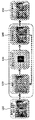
- FIG. 1 is a flowchart illustrating a method of removing blur of an image according to an exemplary embodiment of the present invention.
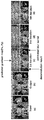
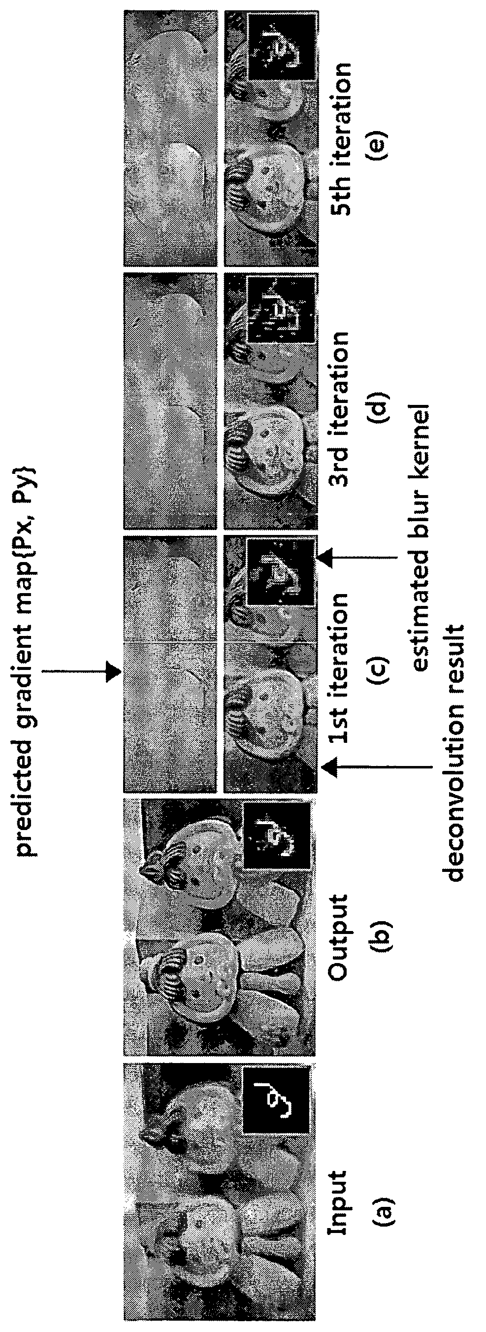
- FIG. 2 is a view illustrating an image in which blur is removed according to the number of iterations performed in the method for removing blur of an image according to an exemplary embodiment of the present invention shown in FIG. 1.
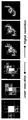
- FIG. 3 is a flowchart showing a more detailed processing of the prediction step shown in FIG.
- FIG. 4 illustrates kernels estimated at different scales in the method for removing blur of an image according to an exemplary embodiment of the present invention.
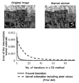
- FIG 5 illustrates the convergence speed of the blur kernel estimation according to an embodiment of the present invention in comparison with the conventional blur kernel estimation method.
- FIG. 6 shows the accuracy of a blur kernel estimation in accordance with an embodiment of the present invention.
- FIG. 7 illustrates an image from which blur is removed using a blur estimation method of an image according to an embodiment of the present invention.
- FIG 8 illustrates an actual image from which blur is removed by using the blur estimation method of an image according to an embodiment of the present invention.
- FIG. 9 shows processing time taken to remove blur of the images shown in FIG. 8.
- first, second, A, and B may be used to describe various components, but the components should not be limited by the terms. The terms are used only for the purpose of distinguishing one component from another.
- the first component may be referred to as the second component, and similarly, the second component may also be referred to as the first component.
- the motion blur may be expressed as Equation 1.
- Equation 1 B means a blurred image
- K means a motion blur kernel or a point spread function (PSF) indicating blur information of an image
- L Is a latent image, that is, a clear image without blur.
- N means unknown noise introduced in the image acquisition process
- * means a convolution operator.
- Equation 2 and Equation 3 Means the data fitting term, And Means normalization terms.
- the goal of iterative optimization is to gradually refine the blur kernel K's accuracy.
- the final image with blur removed is obtained by performing a deconvolution operation on the final blur kernel K and the image B with the given blur.
- the latent image estimated during iterative optimization does not have a direct effect on the final image without blurring, but indirectly affects the final image without blurring by affecting the improvement of the motion blur kernel K.
- noise suppression in the flat area is also important in the general natural image since the flat area occupies more area than the sharp edge area. If the noise is not suppressed in the flat region, the data adjustment term of Equation 3 is significantly affected by the noise, which impairs the accuracy of estimating the blur kernel from the sharp edges.
- the method for blur removal of an image provides a fast blind deconvolution method by reducing the amount of computation in the latent image estimation and blur kernel estimation process.
- a latent image sufficiently includes sharp edges in order to improve the estimation speed of the latent image.
- image filters are used to take advantage of sharp edge recovery and noise suppression.
- Equation 3 the numerical optimization process of Equation 3 is improved by excluding a pixel value.
- the latent image estimation process is largely composed of two stages of simple deconvolution and prediction.
- the blur is removed using a simple fast deconvolution with a Gaussian prior to estimate the lattice image L. . Due to the characteristics of the Gaussian fryer, the latticed image L contains noise at smooth edges and flat areas.
- an image filter is used to obtain sharp edge reconstruction and noise removal to obtain an estimated latticed image L 'with improved accuracy.
- simple edges and suppressed noise in the flat region of the latticed image are used as important features when the latticed image is used for the blur kernel estimation, simple deconvolution results in estimating despite the deterioration of image quality.
- the lattice image L ' provides a high quality lattice image for accurate blur kernel estimation.
- CG conjugate gradient method
- Equation 3 as an energy function with only image derivatives can significantly reduce the number of image demarcations and fast Fourier transforms.
- the formulation of the energy function additionally provides a speedup of the CG, and is well-conditioned with a small condition number in the calculation scheme derived from Equation 3. To provide and improve the speed of convergence.
- FIG. 1 is a flowchart illustrating a method of removing blur of an image according to an exemplary embodiment of the present invention.
- an image including blur is provided (step 110).
- the prediction step (step 120) is located at the beginning of the repeated loop to provide an initial value of the lattice image L for blur kernel estimation when an image with blur is provided.
- the gradient map ⁇ P x , P y ⁇ is calculated along the x direction and the y direction of the latent image L to predict the prominent edge in the latent image where the noise is suppressed in the flat region.
- the input of the prediction step in the iterative performance of steps 120 to 150 is the estimated latent image L obtained by performing the deconvolution step in the previous iteration except for the first time.
- the blur kernel K is estimated using the gradient map ⁇ P x , P y ⁇ and the image B including the blur estimated through the calculation in step 120.
- the latent image L is estimated using the blur kernel K and the image B including the blur.
- the estimated latticed image L is provided as an input of the prediction step (step 120) of the next iteration process.
- the accuracy of the estimation is improved by performing steps 120 and 130 repeatedly to estimate the blur kernel K and the latent image L more effectively.
- a gray scale version of an image B and a latent image L including the blur is used in an iterative process for updating the accuracy of the blur kernel K and the latent image L.
- the final deconvolution step (step 150) is performed repeatedly to obtain the final blur kernel K and then to obtain the final image from which the blur is removed, the final deconvolution for each color channel of the image blur containing the final blur kernel K and the blur.
- the evolution is performed (step 150).
- FIG. 2 is a view illustrating an image in which blur is removed according to the number of iterations performed in the method for removing blur of an image according to an exemplary embodiment of the present invention shown in FIG. 1.
- FIG. 2A illustrates an original image including blur
- FIG. 2B illustrates a final image from which blur is removed according to an embodiment of the present invention.
- (c) to (e) of FIG. 2 shows the results of performing the steps 120 to 140 of FIG. 1 once, three times and five times, respectively, and the predicted gradient map ⁇ P x , P y ⁇ And deconvolution results including the estimated blur kernel.
- Image can be estimated, and a more accurate blur kernel can be predicted based on the estimated lattice image. Then, the blur image is removed to obtain the final image (b) by using the more accurately estimated blur kernel.
- the predicting step (step 120) of FIG. 1 estimates the image gradient map ⁇ P x , P y ⁇ by setting only the gradient in the lattice image L but leaving the other area at zero.
- the convolution of gradient zero is always zero, regardless of the estimated blur kernel, and consequently only prominent edges in the blur kernel estimation step (step 130) affect the blur kernel optimization.
- the prediction step uses a shock filter to reconstruct the strong edges.
- Shock filters are an efficient tool for enhancing the characteristics of an image by restoring sharp edges from an image with blur.
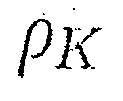
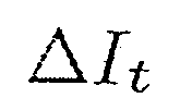
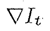
- the shock filter may be expressed as in Equation 4.
- Equation 4 I t means an image at time t, And Denotes Laplacian and gradient of I t , respectively. Dt also means a time step for a single evolution.
- FIG. 3 is a flowchart showing a more detailed processing of the prediction step shown in FIG.
- the prediction step may include a bidirectional filtering step, a shock filtering step, and a gradient threshold applying step.
- a bidirectional filter is applied to suppress the noise and small detail that may exist for the currently estimated latticed image L (step 121).
- the image size supported by bidirectional filtering may be fixed (for example, 5 ⁇ 5).
- a shock filter is applied to reconstruct the strong edges in the estimated latticed image L (step 123).
- the latent image L ' which is the resultant image of the shock filter, is improved in contrast, but at the same time, noise is increased.
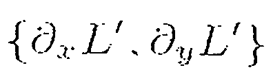
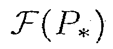
- the gradient map of the latent image L ' Is calculated (step 125), and noise is removed by applying a threshold to the calculated gradient map (truncate) the gradient (step 127).
- the truncated gradient map ⁇ P x , P y ⁇ is the final output of the prediction step.
- the omission of the gradient may be performed by setting, for example, a gradient smaller than a threshold value to zero.
- the threshold for truncating the gradient first divides the direction of the gradient by a predetermined angle (for example, 45 degrees) and generates a histogram according to the gradient size for each direction (here, 180 to 360 degrees).
- the figures may differ only in sign and are computed as angles in the same direction), and for each direction generated may comprise at least a predetermined multiple (e.g. twice) of the maximum of the vertical and horizontal size of the blur kernel. Set the gradient size as the threshold.
- the deconvolution step (step 140) estimates the latent image L based on the given blur kernel K and the image B with the provided blur.
- the energy function may be expressed as in Equation 5.
- Equation 5 Means the partial differential operator and order in different directions, Means the weight for each partial derivative, Denotes a weight (eg, 0.1) for the normalization term.
- Equation 5 can be optimized very quickly through pixel-wise division in the frequency domain through only two fast Fourier operations.
- the optimized result of Equation 5 may include the flat edge and the ringing effect.
- the results of performing a single deconvolution based on prediction step (step 120) do not affect accurate blur kernel estimation.
- a multi-scale iterative process is performed to effectively remove blur from an image including large blur.
- FIG. 4 illustrates kernels estimated at different scales in the method for removing blur of an image according to an exemplary embodiment of the present invention.
- the sharp edge estimation is applied to the deconvolution result obtained through the blur kernel updated in the previous iteration process while performing the iteration at a particular scale.
- a blur kernel for a large blur may be estimated using a small size bidirectional filter and a shock filter through a multi-scale iterative process.
- the multi-scale iterative process makes it possible to estimate large blurs that have not been addressed using one scale.
- the method for removing blur of an image according to an embodiment of the present invention performs two fast Fourier transforms and simple image filtering in gradient map prediction of a latent image for blur kernel estimation, and performs bidirectional filtering, shock filtering, and a gradient threshold. Value application can be done very quickly. This is a very fast process for conventional blur removal methods (e.g. Shan et al. 2008) compared to performing 30 to 60 fast Fourier transforms.
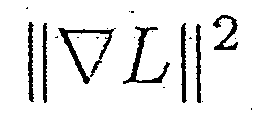
- the blur kernel estimation using the estimated gradient map ⁇ P x , P y ⁇ uses the energy function of Equation 6.
- Equation (6) Is the weight for each partial derivative, And May change as shown in Equation 7.
- the present invention uses only image derivatives without including pixel values in the energy function.
- the present invention uses the Tychonov normalization term instead of the L 1 norm of K used in the conventional blur removal method.
- Equation 6 may be represented again in a deterministic form as shown in Equation 8.
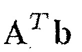
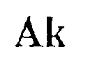
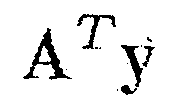
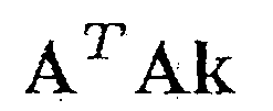
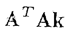
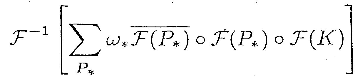
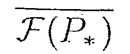
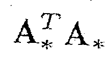
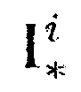
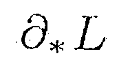
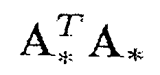
- Equation 10 Is Means a complex conjugate of. Can be precomputed before iteration of the conjugate gradient method (CG). Therefore, the number of fast Fourier transforms can be reduced ten times because only two fast Fourier transforms are performed in the gradient calculation.
- Equation 6 elements having a value smaller than 1/20 of the largest value are set to 0, and then normalized so that the sum is 1 for non-zero values.
- the number of iterations and the speed of convergence for optimization convergence are very important.
- the calculation is optimized at a much faster speed than the conventional case including the pixel value.
- FIG 5 illustrates the convergence speed of the blur kernel estimation according to an embodiment of the present invention in comparison with the conventional blur kernel estimation method.
- the blur kernel estimation error is dramatically reduced through repetition within several times, but the conventional blur kernel estimation method using pixel values is more effective than the present invention. It can be seen that the blur kernel estimation error is reduced more slowly.
- the original version of "Shan et al. 2008” requires more computation because it uses the L 1 norm for the normalization term of the energy function.
- a large sized matrix is generated, which causes a shortage of memory and an excessive amount of computation.
- the blur kernel estimation according to an embodiment of the present invention performs two fast Fourier transforms at each step of the Gradient Gradient Method (CG), but "Shan-L2" performs one pixel value image and five partial derivatives. Since we use six images of images, we perform a total of 14 fast Fourier transforms. In addition, since “Shan-L2" uses a pixel value, more iterations are required than the present invention.
- CG Gradient Gradient Method
- the blur kernel estimation method according to an embodiment of the present invention is 40 times faster than "Shan-L2" and 10 times faster than other conventional methods using pixel values.
- FIG. 6 shows the accuracy of a blur kernel estimation in accordance with an embodiment of the present invention.
- the present invention is compared with the conventional method using pixel values by using test images added with different Gaussian noise.
- the kernel estimating method according to an embodiment of the present invention has substantially the same accuracy as the conventional kernel estimating method using pixel values despite not using pixel values.
- the kernel estimation method of the present invention has better accuracy than conventional kernel estimation methods using pixel values due to the well-defined calculation scheme obtained by excluding pixel values.
- FIG. 7 illustrates an image from which blur is removed using a blur estimation method of an image according to an embodiment of the present invention.
- the estimated blur kernel is substantially the same as the original blur kernel, and the image from which the blur is removed accurately restores the fine detail of the original image.
- FIG. 8 illustrates an actual image from which blur is removed by using the blur estimation method of an image according to an embodiment of the present invention.
- Each image shown in FIG. 8 includes different complex structures and camera motions.
- each image of which blur has been removed has a sharpening of sharp edges to more clearly show the shape and structure of an object.
- FIG. 9 shows processing time taken to remove blur of the images shown in FIG. 8.
- the experimental environment is a PC with an Intel Core 2 CPU 2.66GHz, 3.25GB RAM, and an NVIDIA GeForce GTX graphics card based on MS Windows XP (32bit).
- the blur removal method implemented for the experiment was implemented using the GPU acceleration function of the graphics card.
- the method for removing blur of an image may remove blur within a few seconds from an image including an input blur even when a kernel size is large.
Landscapes
- Engineering & Computer Science (AREA)
- Physics & Mathematics (AREA)
- General Physics & Mathematics (AREA)
- Theoretical Computer Science (AREA)
- Multimedia (AREA)
- Image Processing (AREA)
- Facsimile Image Signal Circuits (AREA)
- Studio Devices (AREA)
Abstract
Description

수학식 2

수학식 3

수학식 2 및 수학식 3에서

수학식 4

수학식 4에서, It 는 시간 t에서의 이미지를 의미하고,
따라서, 레이턴트 이미지 L'의 그라디언트 맵
수학식 5

수학식 5에서,



수학식 5의 첫번째 항은 링잉 효과(ringing artifacts)를 감소시키기 위해 이미지 도함수를 사용하는 Shan 등(SHAN, Q., JIA, J., AND AGARWALA, A. 2008. High-quality motion deblurring from a single image. ACM Trans. Graphics 27, 73.)이 제안한 블러 모델에 기초한다. 또한, 정규화 항
수학식 6

수학식 6에서

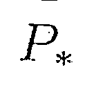

수학식 7
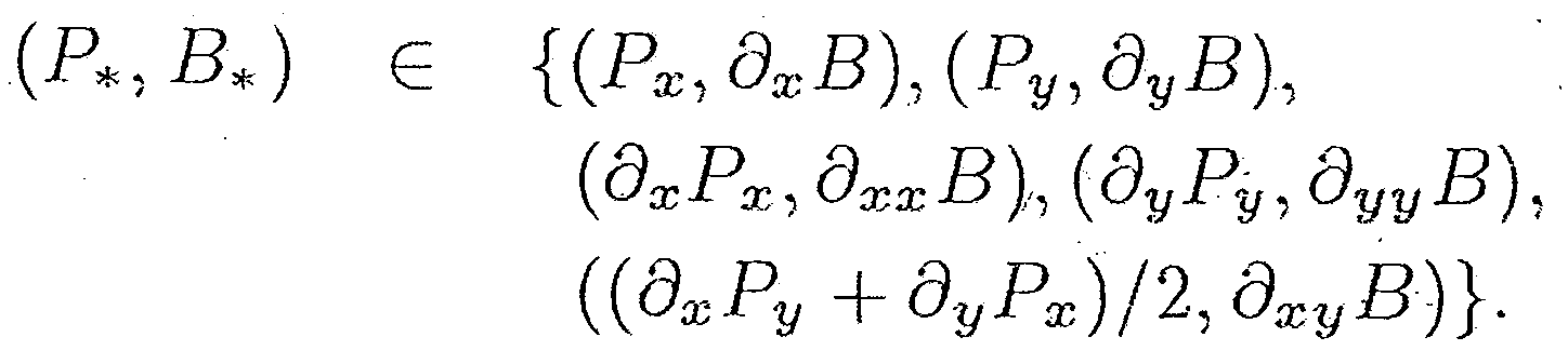
수학식 6에서 각


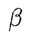
수학식 8

수학식 8에서

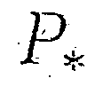
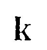
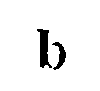
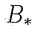
수학식 8을 최소화하기 위해 켤레 구배법(CG)를 사용하면,
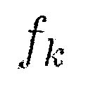
수학식 9

수학식 9에서
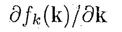
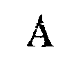



그러나,
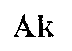
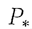



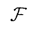
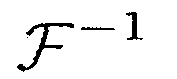

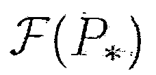
상술한 방법과 유사하게 여섯 번의 고속 푸리에 변환을 통해
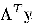

결과적으로, 켤레 구배법(CG)의 각 반복 단계에서 그라디언트

본 발명에서는 고속 푸리에 변환의 회수를 감소시킴으로써 계산 속도를 더욱 향상시키기 위해
수학식 10
수학식 10에서,
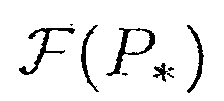
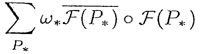
상술한 바와 같은 효율적인 계산은 수학식 6에서 픽셀 값을 사용하지 않고 이미지 도함수만을 사용하는데서 기인한다. 즉, 본 발명에서는 단지 이미지 편미분만을 사용하기 때문에

상기한 바와 같이 계산 최적화의 빠른 수렴은 수학식 9에서 행렬
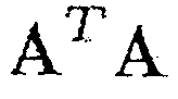

수학식 11
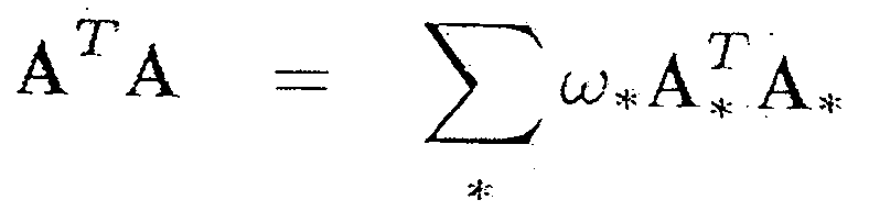
수학식 11에서


Claims (9)
- 블러가 포함된 이미지를 제공받는 단계;제공된 상기 블러가 포함된 이미지로부터 블러가 없는 이미지를 추정 하는 이미지 추정 단계;상기 블러가 포함된 이미지 및 추정된 상기 블러가 없는 이미지로부터 블러 정보를 추정하는 블러 정보 추정 단계; 및상기 블러가 포함된 이미지 및 추정된 상기 블러 정보에 기초하여 상기 블러가 포함된 이미지에서 블러를 제거하는 블러 제거 단계를 포함하되,상기 이미지 추정 단계 및 상기 블러 정보 추정 단계는 반복적으로 수행하는 것을 특징으로 하는 이미지의 블러 제거 방법.
- 제1항에 있어서, 상기 선명한 이미지 추정 단계는,상기 블러가 포함된 이미지의 그라디언트(gradient) 정보를 예측하는 그라디언트 정보 예측 단계; 및상기 추정된 블러 정보 및 상기 블러가 포함된 이미지에 기초하여 제1 디컨볼루션을 수행하는 제1 디컨볼루션 수행 단계를 포함하는 것을 특징으로 하는 이미지의 블러 제거 방법.
- 제2항에 있어서, 상기 그라디언트 정보 예측 단계는,상기 블러가 포함된 이미지에 양방향 필터를 적용하는 단계;상기 양방향 필터가 적용된 이미지에 쇼크 필터를 적용하는 단계;상기 쇼크 필터가 적용된 이미지의 그라디언트 맵을 산출하는 단계;산출된 상기 그라디언트 맵에 임계값을 적용하는 단계를 포함하는 것을 특징으로 하는 이미지의 블러 제거 방법.
- 제3항에 있어서, 상기 산출된 상기 그라디언트 맵에 임계값을 적용하는 단계는,상기 산출된 그라디언트의 방향 및 크기에 기초하여 히스토그램을 생성하는 단계;상기 생성된 히스토그램에 포함된 각 방향에 상응하는 블러 정보의 수직 및 수평 크기 중 최대값의 소정 배수 이상의 픽셀을 포함할 수 있는 그라디언트의 크기를 임계값으로 설정하는 단계; 및설정된 상기 임계값을 상기 그라디언트 맵에 적용하여 그라디언트를 생략(truncate)하는 단계를 포함하는 이미지의 블러 제거 방법.
- 제4항에 있어서, 상기 설정된 상기 임계값을 상기 그라디언트 맵에 적용하여 그라디언트를 생략(truncate)하는 단계는,상기 임계값보다 작은 그라디언트를 0으로 설정하는 것을 특징으로 하는 이미지의 블러 제거 방법.
- 제4항에 있어서, 상기 블러 정보 추정 단계는,상기 블러가 포함된 이미지 및 상기 생략된 그라디언트에 기초하여 상기 블러 정보를 추정하는 것을 특징으로 하는 이미지의 블러 제거 방법.
- 제4항에 있어서, 상기 블러 정보 추정 단계는,픽셀 값을 포함시키지 않고 이미지 도함수만을 포함하는 에너지 함수를 이용하여 블러 정보를 추정하는 것을 특징으로 하는 이미지의 블러 제거 방법.
- 제1항에 있어서, 상기 이미지 추정 단계 및 상기 블러 정보 추정 단계는,상기 블러가 포함된 이미지 및 상기 추정된 블러가 없는 이미지의 해상도를 변화시키면서 반복적으로 수행되는 것을 특징으로 하는 이미지의 블러 제거 방법.
- 이미지에 포함된 블러의 제거를 수행하는 디지털 처리 장치에 의해 실행될 수 있는 명령어의 프로그램이 유형적으로 구현되어 있으며, 상기 디지털 처리 장치에 의해 판독될 수 있는 프로그램을 기록한 기록 매체에 있어서,블러가 포함된 이미지를 제공받는 단계;제공된 상기 블러가 포함된 이미지로부터 블러가 없는 이미지를 추정 하는 이미지 추정 단계;상기 블러가 포함된 이미지 및 추정된 상기 블러가 없는 이미지로부터 블러 정보를 추정하는 블러 정보 추정 단계; 및상기 블러가 포함된 이미지 및 추정된 상기 블러 정보에 기초하여 상기 블러가 포함된 이미지에서 블러를 제거하는 블러 제거 단계를 수행하되,상기 이미지 추정 단계 및 상기 블러 정보 추정 단계는 반복적으로 수행하는 프로그램을 기록한 기록 매체.
Priority Applications (2)
| Application Number | Priority Date | Filing Date | Title |
|---|---|---|---|
| CN200980155499.0A CN102326379B (zh) | 2008-12-31 | 2009-10-12 | 从图像中去除模糊的方法 |
| DE112009004059.4T DE112009004059B4 (de) | 2008-12-31 | 2009-10-12 | Verfahren zum Entfernen von Unschärfe von einem Bild und Aufzeichnungsmedium, auf dem das Verfahren aufgezeichnet ist |
Applications Claiming Priority (2)
| Application Number | Priority Date | Filing Date | Title |
|---|---|---|---|
| KR10-2008-0138195 | 2008-12-31 | ||
| KR1020080138195A KR100990791B1 (ko) | 2008-12-31 | 2008-12-31 | 영상의 블러 제거 방법 및 블러 제거 방법이 기록된 기록매체 |
Publications (2)
| Publication Number | Publication Date |
|---|---|
| WO2010076945A2 true WO2010076945A2 (ko) | 2010-07-08 |
| WO2010076945A3 WO2010076945A3 (ko) | 2010-08-12 |
Family
ID=42285081
Family Applications (1)
| Application Number | Title | Priority Date | Filing Date |
|---|---|---|---|
| PCT/KR2009/005825 Ceased WO2010076945A2 (ko) | 2008-12-31 | 2009-10-12 | 이미지의 블러 제거 방법 및 이미지의 블러 제거 방법이 기록된 기록매체 |
Country Status (6)
| Country | Link |
|---|---|
| US (1) | US8380000B2 (ko) |
| JP (1) | JP4938070B2 (ko) |
| KR (1) | KR100990791B1 (ko) |
| CN (1) | CN102326379B (ko) |
| DE (1) | DE112009004059B4 (ko) |
| WO (1) | WO2010076945A2 (ko) |
Cited By (1)
| Publication number | Priority date | Publication date | Assignee | Title |
|---|---|---|---|---|
| KR20210056212A (ko) * | 2019-11-08 | 2021-05-18 | 한국전기연구원 | 하이브리드 펄스를 이용한 엑스선 영상 획득 및 처리 방법, 장치 및 시스템 |
Families Citing this family (45)
| Publication number | Priority date | Publication date | Assignee | Title |
|---|---|---|---|---|
| WO2011049565A1 (en) * | 2009-10-21 | 2011-04-28 | Hewlett-Packard Development Company, L.P. | Real-time video deblurring |
| JP5184574B2 (ja) * | 2010-04-30 | 2013-04-17 | パナソニック株式会社 | 撮像装置、画像処理装置、および画像処理方法 |
| CN101986345B (zh) * | 2010-11-04 | 2012-06-06 | 浙江大学 | 一种图像去模糊方法 |
| US9535537B2 (en) * | 2010-11-18 | 2017-01-03 | Microsoft Technology Licensing, Llc | Hover detection in an interactive display device |
| CN102572201B (zh) * | 2010-12-31 | 2015-01-28 | 北京大学 | 一种图像网纹去除方法及系统 |
| KR101839617B1 (ko) * | 2011-07-11 | 2018-03-19 | 포항공과대학교 산학협력단 | 멀티프레임을 이용한 비균일 모션 블러 제거 방법 및 장치 |
| US8705881B2 (en) * | 2011-09-02 | 2014-04-22 | Adobe Systems Incorporated | Motion deblurring for text images |
| JP5910043B2 (ja) * | 2011-12-02 | 2016-04-27 | 富士通株式会社 | 撮像装置、画像処理プログラム、画像処理方法、および画像処理装置 |
| JP2013152583A (ja) * | 2012-01-25 | 2013-08-08 | Nagoya Institute Of Technology | 画像処理装置 |
| CN102708541B (zh) * | 2012-02-22 | 2015-01-14 | 贵州大学 | 微扰法解图像模糊 |
| KR101810876B1 (ko) * | 2012-03-13 | 2018-01-26 | 삼성전자주식회사 | 타일 단위를 기반으로 큰 입력 영상의 비균일 모션 블러를 제거하는 방법 및 장치 |
| WO2013148139A1 (en) | 2012-03-29 | 2013-10-03 | Nikon Corporation | Algorithm for minimizing latent sharp image and point spread function cost functions with spatial mask fidelity |
| US9262815B2 (en) | 2012-03-29 | 2016-02-16 | Nikon Corporation | Algorithm for minimizing latent sharp image cost function and point spread function cost function with a spatial mask in a regularization term |
| US9202265B2 (en) * | 2012-04-30 | 2015-12-01 | Nikon Corporation | Point spread function cost function with non-uniform weights |
| US8867856B2 (en) | 2012-11-12 | 2014-10-21 | Adobe Systems Incorporated | De-noising image content using directional filters for image de-blurring |
| CN103337055B (zh) * | 2013-06-24 | 2016-07-20 | 暨南大学 | 一种基于梯度拟合的文本图像去模糊方法 |
| WO2015017194A1 (en) * | 2013-07-29 | 2015-02-05 | Nikon Corporation | Multiple phase method for image deconvolution |
| US9430817B2 (en) | 2013-11-12 | 2016-08-30 | Microsoft Technology Licensing, Llc | Blind image deblurring with cascade architecture |
| US9659351B2 (en) * | 2014-03-12 | 2017-05-23 | Purdue Research Foundation | Displaying personalized imagery for improving visual acuity |
| CN104932868B (zh) * | 2014-03-17 | 2019-01-15 | 联想(北京)有限公司 | 一种数据处理方法及电子设备 |
| CN105096261B (zh) * | 2014-05-13 | 2018-04-17 | 北京大学 | 图像处理装置和图像处理方法 |
| CN105469363B (zh) | 2014-09-05 | 2018-05-18 | 华为技术有限公司 | 基于模糊图像生成清晰图像的方法和装置 |
| CN104794691B (zh) * | 2015-04-07 | 2017-06-23 | 浙江大学 | 利用广义高斯模型进行单张失焦图像清晰重建的方法 |
| KR101624503B1 (ko) | 2015-05-11 | 2016-05-26 | 한화탈레스 주식회사 | 번짐 영상의 복원 방법 |
| CN105493140B (zh) * | 2015-05-15 | 2018-02-02 | 北京大学深圳研究生院 | 图像去模糊方法及系统 |
| KR101596203B1 (ko) * | 2015-06-16 | 2016-02-22 | 중앙대학교 산학협력단 | 모션 블러 이미지 복원 방법 및 장치 |
| JP6541454B2 (ja) * | 2015-06-17 | 2019-07-10 | キヤノン株式会社 | 画像処理装置、撮像装置、画像処理方法、画像処理プログラム、および、記憶媒体 |
| JP2017010092A (ja) * | 2015-06-17 | 2017-01-12 | キヤノン株式会社 | 画像処理装置、撮像装置、画像処理方法、画像処理プログラム、および、記憶媒体 |
| KR101671391B1 (ko) * | 2015-07-07 | 2016-11-02 | 한국과학기술연구원 | 레이어 블러 모델에 기반한 비디오 디블러링 방법, 이를 수행하기 위한 기록 매체 및 장치 |
| US9852330B1 (en) | 2015-07-27 | 2017-12-26 | United Launch Alliance, L.L.C. | System and method to enable the application of optical tracking techniques for generating dynamic quantities of interest with alias protection |
| US11354881B2 (en) | 2015-07-27 | 2022-06-07 | United Launch Alliance, L.L.C. | System and method to enable the application of optical tracking techniques for generating dynamic quantities of interest with alias protection |
| CN105512461B (zh) * | 2015-11-26 | 2019-02-12 | 深圳市华星光电技术有限公司 | 背光源mura值的计算方法、系统及检测装置 |
| CN105957043B (zh) * | 2016-06-22 | 2018-12-14 | 西北工业大学 | 基于梯度自动激活的模糊图像盲复原方法 |
| WO2018097677A1 (en) | 2016-11-28 | 2018-05-31 | Samsung Electronics Co., Ltd. | Image processing apparatus, image processing method, and computer-readable recording medium thereof |
| KR101862490B1 (ko) | 2016-12-13 | 2018-05-29 | 삼성전기주식회사 | 영상 보정 프로세서 및 컴퓨터 판독가능 기록 매체 |
| US10628995B2 (en) | 2017-04-17 | 2020-04-21 | Microsoft Technology Licensing, Llc | Anti-aliasing of graphical elements defined based on functions |
| CN107610056B (zh) * | 2017-08-11 | 2020-08-11 | 南京信息工程大学 | 基于全变分的混合加权维纳滤波图像去噪方法 |
| US11276159B1 (en) | 2018-05-15 | 2022-03-15 | United Launch Alliance, L.L.C. | System and method for rocket engine health monitoring using digital image correlation (DIC) |
| KR102126916B1 (ko) | 2018-11-30 | 2020-06-26 | 동국대학교 산학협력단 | 블러된 영상 복원을 위한 장치 및 방법 |
| CN110874826B (zh) * | 2019-11-18 | 2020-07-31 | 北京邮电大学 | 应用于离子束精准镀膜的工件图像去雾化方法及装置 |
| US20220405882A1 (en) * | 2021-06-22 | 2022-12-22 | Gopro, Inc. | Convolutional neural network super-resolution system and method |
| DE102021004828B4 (de) | 2021-09-24 | 2025-12-11 | Mercedes-Benz Group AG | Verfahren zur kamerabasierten Bestimmung eines Abstands in einem Fahrzeuginnenraum und Fahrzeug mit einer Kamera |
| US12555206B2 (en) | 2021-12-20 | 2026-02-17 | POSTECH Research and Business Development Foundation | Inverse kernel-based defocus deblurring method and apparatus |
| CN116612048B (zh) * | 2023-07-17 | 2023-09-26 | 山东产研卫星信息技术产业研究院有限公司 | 一种光学卫星遥感影像去模糊处理方法及系统 |
| CN118822962B (zh) * | 2024-06-21 | 2025-04-08 | 长光卫星技术股份有限公司 | 一种高分辨率光学遥感影像模糊退化自动监测方法 |
Family Cites Families (13)
| Publication number | Priority date | Publication date | Assignee | Title |
|---|---|---|---|---|
| JPH0832839A (ja) * | 1994-07-19 | 1996-02-02 | Sharp Corp | 雑音除去装置 |
| JP4344968B2 (ja) | 1999-10-28 | 2009-10-14 | ソニー株式会社 | 画像処理装置および画像処理方法、並びにデータ処理装置およびデータ処理方法 |
| US7440634B2 (en) * | 2003-06-17 | 2008-10-21 | The Trustees Of Columbia University In The City Of New York | Method for de-blurring images of moving objects |
| US7728844B2 (en) * | 2004-07-09 | 2010-06-01 | Nokia Corporation | Restoration of color components in an image model |
| KR100688536B1 (ko) | 2005-03-09 | 2007-03-02 | 삼성전자주식회사 | 영상신호 잡음제거장치 및 영상신호 잡음제거방법 |
| CN1904941A (zh) * | 2005-07-29 | 2007-01-31 | 清华大学 | 一种图像处理中的去模糊方法 |
| US20070165961A1 (en) * | 2006-01-13 | 2007-07-19 | Juwei Lu | Method And Apparatus For Reducing Motion Blur In An Image |
| US7587099B2 (en) * | 2006-01-27 | 2009-09-08 | Microsoft Corporation | Region-based image denoising |
| JP2007334457A (ja) * | 2006-06-12 | 2007-12-27 | Toshiba Corp | 画像処理装置及び画像処理方法 |
| US20080137978A1 (en) * | 2006-12-07 | 2008-06-12 | Guoyi Fu | Method And Apparatus For Reducing Motion Blur In An Image |
| JP4799428B2 (ja) * | 2007-01-22 | 2011-10-26 | 株式会社東芝 | 画像処理装置及び方法 |
| KR101399012B1 (ko) * | 2007-09-12 | 2014-05-26 | 삼성전기주식회사 | 영상 복원 장치 및 방법 |
| JP2009182576A (ja) * | 2008-01-30 | 2009-08-13 | Canon Inc | 画像処理装置、撮像装置、印刷装置及び画像処理方法 |
-
2008
- 2008-12-31 KR KR1020080138195A patent/KR100990791B1/ko active Active
-
2009
- 2009-10-12 DE DE112009004059.4T patent/DE112009004059B4/de active Active
- 2009-10-12 CN CN200980155499.0A patent/CN102326379B/zh active Active
- 2009-10-12 WO PCT/KR2009/005825 patent/WO2010076945A2/ko not_active Ceased
- 2009-10-16 JP JP2009239797A patent/JP4938070B2/ja not_active Expired - Fee Related
- 2009-10-16 US US12/580,975 patent/US8380000B2/en not_active Expired - Fee Related
Cited By (2)
| Publication number | Priority date | Publication date | Assignee | Title |
|---|---|---|---|---|
| KR20210056212A (ko) * | 2019-11-08 | 2021-05-18 | 한국전기연구원 | 하이브리드 펄스를 이용한 엑스선 영상 획득 및 처리 방법, 장치 및 시스템 |
| KR102801623B1 (ko) | 2019-11-08 | 2025-05-07 | 한국전기연구원 | 하이브리드 펄스를 이용한 엑스선 영상 획득 및 처리 방법, 장치 및 시스템 |
Also Published As
| Publication number | Publication date |
|---|---|
| US20100166332A1 (en) | 2010-07-01 |
| KR100990791B1 (ko) | 2010-10-29 |
| JP2010157210A (ja) | 2010-07-15 |
| CN102326379A (zh) | 2012-01-18 |
| DE112009004059T5 (de) | 2012-07-12 |
| KR20100079658A (ko) | 2010-07-08 |
| JP4938070B2 (ja) | 2012-05-23 |
| US8380000B2 (en) | 2013-02-19 |
| WO2010076945A3 (ko) | 2010-08-12 |
| CN102326379B (zh) | 2014-11-05 |
| DE112009004059B4 (de) | 2017-07-27 |
Similar Documents
| Publication | Publication Date | Title |
|---|---|---|
| WO2010076945A2 (ko) | 이미지의 블러 제거 방법 및 이미지의 블러 제거 방법이 기록된 기록매체 | |
| Cho et al. | Fast motion deblurring | |
| EP2189939B1 (en) | Image restoration from multiple images | |
| Faramarzi et al. | Unified blind method for multi-image super-resolution and single/multi-image blur deconvolution | |
| Tom et al. | Reconstruction of a high resolution image from registration and restoration of low resolution images | |
| WO2022092900A1 (en) | Method and device for training a super-resolution network | |
| US20130058588A1 (en) | Motion Deblurring Using Image Upsampling | |
| KR101839617B1 (ko) | 멀티프레임을 이용한 비균일 모션 블러 제거 방법 및 장치 | |
| WO2016183716A1 (zh) | 图像去模糊方法及系统 | |
| KR20130104258A (ko) | 블러 영상 및 노이즈 영상으로 구성된 멀티 프레임을 이용하여 비균일 모션 블러를 제거하는 방법 및 장치 | |
| Repetti et al. | A penalized weighted least squares approach for restoring data corrupted with signal-dependent noise | |
| CN111047544A (zh) | 一种基于非线性退化模型的饱和图像去模糊方法 | |
| Xu et al. | Image deblurring with blur kernel estimation in RGB channels | |
| CN103093436B (zh) | 利用图像局部结构方向导数的模糊核多尺度迭代估计方法 | |
| WO2022270854A1 (ko) | 선예도 개선을 위한 심층 기울기 사전정보기반 l0 스무딩 방법 | |
| CN117115044A (zh) | 图像盲去运动模糊方法、装置、电子设备及存储介质 | |
| Mery et al. | A fast non-iterative algorithm for the removal of blur caused by uniform linear motion in X-ray images | |
| Wang et al. | Color image restoration based on saturation-value total variation plus L1 fidelity | |
| JP4859516B2 (ja) | 画像処理装置および画像復元方法 | |
| Ono et al. | Poisson image restoration with likelihood constraint via hybrid steepest descent method | |
| van Zwanenberg et al. | A tool for deriving camera spatial frequency response from natural scenes (NS-SFR) | |
| WO2024111931A1 (en) | Airy-disk correction for deblurring image | |
| Subbarao et al. | Localized and computationally efficient approach to shift-variant image deblurring | |
| Ng et al. | Regularized blind deconvolution using recursive inverse filtering | |
| LI et al. | Double-channel cyclic image deblurring algorithm based on edge features. |
Legal Events
| Date | Code | Title | Description |
|---|---|---|---|
| WWE | Wipo information: entry into national phase |
Ref document number: 200980155499.0 Country of ref document: CN |
|
| 121 | Ep: the epo has been informed by wipo that ep was designated in this application |
Ref document number: 09836266 Country of ref document: EP Kind code of ref document: A2 |
|
| WWE | Wipo information: entry into national phase |
Ref document number: 112009004059 Country of ref document: DE Ref document number: 1120090040594 Country of ref document: DE |
|
| 122 | Ep: pct application non-entry in european phase |
Ref document number: 09836266 Country of ref document: EP Kind code of ref document: A2 |