WO2010076883A1 - Solid electrolytic capacitor - Google Patents
Solid electrolytic capacitor Download PDFInfo
- Publication number
- WO2010076883A1 WO2010076883A1 PCT/JP2009/071789 JP2009071789W WO2010076883A1 WO 2010076883 A1 WO2010076883 A1 WO 2010076883A1 JP 2009071789 W JP2009071789 W JP 2009071789W WO 2010076883 A1 WO2010076883 A1 WO 2010076883A1
- Authority
- WO
- WIPO (PCT)
- Prior art keywords
- anode
- connection piece
- base frame
- lead terminal
- anode lead
- Prior art date
Links
- 239000003990 capacitor Substances 0.000 title claims abstract description 165
- 239000007787 solid Substances 0.000 title claims abstract description 90
- WABPQHHGFIMREM-UHFFFAOYSA-N lead(0) Chemical compound [Pb] WABPQHHGFIMREM-UHFFFAOYSA-N 0.000 claims abstract description 107
- 230000003014 reinforcing effect Effects 0.000 claims abstract description 44
- 238000007789 sealing Methods 0.000 claims abstract description 39
- 229920003002 synthetic resin Polymers 0.000 claims abstract description 11
- 239000000057 synthetic resin Substances 0.000 claims abstract description 11
- 238000005452 bending Methods 0.000 claims description 42
- 238000003466 welding Methods 0.000 claims description 16
- 238000004519 manufacturing process Methods 0.000 claims description 15
- 238000000034 method Methods 0.000 claims description 8
- 230000000630 rising effect Effects 0.000 claims description 7
- 238000005259 measurement Methods 0.000 claims description 5
- 230000002787 reinforcement Effects 0.000 claims description 4
- 230000035515 penetration Effects 0.000 claims description 3
- 238000009434 installation Methods 0.000 claims description 2
- 239000000047 product Substances 0.000 description 31
- 230000000052 comparative effect Effects 0.000 description 29
- 238000012986 modification Methods 0.000 description 12
- 230000004048 modification Effects 0.000 description 12
- 230000000694 effects Effects 0.000 description 7
- 229920005989 resin Polymers 0.000 description 5
- 239000011347 resin Substances 0.000 description 5
- 230000035882 stress Effects 0.000 description 5
- BQCADISMDOOEFD-UHFFFAOYSA-N Silver Chemical compound [Ag] BQCADISMDOOEFD-UHFFFAOYSA-N 0.000 description 4
- 230000007547 defect Effects 0.000 description 4
- 229910052709 silver Inorganic materials 0.000 description 4
- 239000004332 silver Substances 0.000 description 4
- 239000000853 adhesive Substances 0.000 description 3
- 230000001070 adhesive effect Effects 0.000 description 3
- 238000005516 engineering process Methods 0.000 description 3
- 238000003825 pressing Methods 0.000 description 3
- 238000004080 punching Methods 0.000 description 3
- 238000011161 development Methods 0.000 description 2
- 230000018109 developmental process Effects 0.000 description 2
- 238000006073 displacement reaction Methods 0.000 description 2
- 239000003822 epoxy resin Substances 0.000 description 2
- 229920000647 polyepoxide Polymers 0.000 description 2
- 230000002265 prevention Effects 0.000 description 2
- OKTJSMMVPCPJKN-UHFFFAOYSA-N Carbon Chemical compound [C] OKTJSMMVPCPJKN-UHFFFAOYSA-N 0.000 description 1
- 229910000881 Cu alloy Inorganic materials 0.000 description 1
- 230000032683 aging Effects 0.000 description 1
- 230000015572 biosynthetic process Effects 0.000 description 1
- 229910052799 carbon Inorganic materials 0.000 description 1
- 238000006243 chemical reaction Methods 0.000 description 1
- 239000011248 coating agent Substances 0.000 description 1
- 238000000576 coating method Methods 0.000 description 1
- 229920001940 conductive polymer Polymers 0.000 description 1
- 238000012217 deletion Methods 0.000 description 1
- 230000037430 deletion Effects 0.000 description 1
- 238000011156 evaluation Methods 0.000 description 1
- 239000012467 final product Substances 0.000 description 1
- 230000014509 gene expression Effects 0.000 description 1
- 238000005304 joining Methods 0.000 description 1
- 239000000463 material Substances 0.000 description 1
- 238000000465 moulding Methods 0.000 description 1
- 230000002093 peripheral effect Effects 0.000 description 1
- 229920000128 polypyrrole Polymers 0.000 description 1
- 239000004065 semiconductor Substances 0.000 description 1
- 239000000126 substance Substances 0.000 description 1
- 229910052715 tantalum Inorganic materials 0.000 description 1
- GUVRBAGPIYLISA-UHFFFAOYSA-N tantalum atom Chemical compound [Ta] GUVRBAGPIYLISA-UHFFFAOYSA-N 0.000 description 1
- 238000012360 testing method Methods 0.000 description 1
- 238000001721 transfer moulding Methods 0.000 description 1
Images


Classifications
-
- H—ELECTRICITY
- H01—ELECTRIC ELEMENTS
- H01G—CAPACITORS; CAPACITORS, RECTIFIERS, DETECTORS, SWITCHING DEVICES OR LIGHT-SENSITIVE DEVICES, OF THE ELECTROLYTIC TYPE
- H01G9/00—Electrolytic capacitors, rectifiers, detectors, switching devices, light-sensitive or temperature-sensitive devices; Processes of their manufacture
- H01G9/004—Details
- H01G9/008—Terminals
- H01G9/012—Terminals specially adapted for solid capacitors
-
- H—ELECTRICITY
- H01—ELECTRIC ELEMENTS
- H01G—CAPACITORS; CAPACITORS, RECTIFIERS, DETECTORS, SWITCHING DEVICES OR LIGHT-SENSITIVE DEVICES, OF THE ELECTROLYTIC TYPE
- H01G9/00—Electrolytic capacitors, rectifiers, detectors, switching devices, light-sensitive or temperature-sensitive devices; Processes of their manufacture
- H01G9/15—Solid electrolytic capacitors
-
- H—ELECTRICITY
- H01—ELECTRIC ELEMENTS
- H01G—CAPACITORS; CAPACITORS, RECTIFIERS, DETECTORS, SWITCHING DEVICES OR LIGHT-SENSITIVE DEVICES, OF THE ELECTROLYTIC TYPE
- H01G9/00—Electrolytic capacitors, rectifiers, detectors, switching devices, light-sensitive or temperature-sensitive devices; Processes of their manufacture
- H01G9/004—Details
- H01G9/08—Housing; Encapsulation
- H01G9/10—Sealing, e.g. of lead-in wires
-
- Y—GENERAL TAGGING OF NEW TECHNOLOGICAL DEVELOPMENTS; GENERAL TAGGING OF CROSS-SECTIONAL TECHNOLOGIES SPANNING OVER SEVERAL SECTIONS OF THE IPC; TECHNICAL SUBJECTS COVERED BY FORMER USPC CROSS-REFERENCE ART COLLECTIONS [XRACs] AND DIGESTS
- Y10—TECHNICAL SUBJECTS COVERED BY FORMER USPC
- Y10T—TECHNICAL SUBJECTS COVERED BY FORMER US CLASSIFICATION
- Y10T29/00—Metal working
- Y10T29/49—Method of mechanical manufacture
- Y10T29/49002—Electrical device making
- Y10T29/49117—Conductor or circuit manufacturing
- Y10T29/49204—Contact or terminal manufacturing
Definitions
- the present invention relates to a solid electrolytic capacitor in which a capacitor element is sealed with a synthetic resin exterior sealing body and related technology.
- a surface mount type solid electrolytic capacitor in which a capacitor element is sealed with a synthetic resin has an anode lead terminal connected to an anode lead wire protruding from the front end surface of the capacitor element and a cathode provided on the outer periphery of the capacitor element.
- a cathode lead terminal is connected to the layer, and the capacitor element with these terminals has a structure sealed with resin except for a part of the lead terminal.
- This type of solid electrolytic capacitor is usually mounted and used on an electronic board or the like in an electronic device such as a personal computer.
- an electronic device such as a personal computer.
- solid electrolytic capacitors have been designed to increase the capacity by increasing the volume of the capacitor element by increasing the efficiency of the internal structure.
- a standing connection piece is provided in a rising shape on the anode lead terminal, and the anode lead wire is brought into contact with the upper end edge of the standing connection piece.
- the contact area can be reduced, and the capacity of the capacitor element can be increased accordingly.
- the lead wire is connected to the upper end edge of the standing connection piece of the lead terminal.
- the standing connection piece is deformed by the stress at the time of fixing the connection, which may cause a connection failure.
- the present invention has been made in view of the above problems, and provides a solid electrolytic capacitor and related technology capable of reliably connecting a lead terminal and a lead wire while increasing the capacity of a capacitor element. For the purpose.
- the connected cathode lead terminal is a solid electrolytic capacitor that is sealed by a synthetic resin exterior sealing body except for a part of the anode lead terminal and the cathode lead terminal,
- the anode lead terminal corresponds to the anode lead wire, and is disposed along the lower surface of the exterior sealing body.
- the anode lead terminal extends from the edge of the anode base frame along the front end surface of the capacitor element. And a reinforcing piece provided between both side edges of the standing connection piece and both side edges of the anode base frame. And a solid electrolytic capacitor.
- the cathode lead terminal includes a cathode base frame disposed along a lower surface of the rear portion of the exterior sealing body, and a flat connection piece bonded to the lower surface of the capacitor element.
- the solid electrolytic capacitor according to any one of 7 above.
- An anode base frame, an upright connection piece arranged in an upright manner from an edge of the anode base frame, and reinforcing pieces provided between both side edges of the upright connection piece and the two edge measurements of the anode base frame Preparing a prepared anode lead terminal; Preparing a cathode lead terminal; The anode lead terminal is bonded and fixed to the upper end edge of the standing connection piece in a state where the anode base frame is disposed below the front part of the capacitor element; Bonding and fixing the cathode lead terminal to the cathode layer of the capacitor element;
- a flat product for an anode lead terminal provided with a single region is prepared in advance,
- the step of preparing the anode lead terminal includes the step of forming the standing connection piece by bending the standing connection piece region of the developed product for the anode lead terminal with respect to the anode base frame region, and the anode REIT.
- the manufacturing method of the solid electrolytic capacitor of the preceding clause 11 including the process of pushing and bending the said reinforcement piece area
- a solid electrolytic capacitor that is electrically connected to the anode lead wire protruding from the front end face of the capacitor element and is sealed with a synthetic resin exterior sealing body together with the capacitor element except for a part thereof Anode lead terminal, An anode base frame having a flat shape, an upright connection piece arranged in an upright manner at an edge of the anode base frame and joined to the anode lead wire, both side edges of the upright connection piece and the anode An anode lead terminal for a solid electrolytic capacitor, comprising reinforcing pieces provided at both side edges of the base frame.
- the standing connection piece of the anode lead terminal can be easily formed.
- the reinforcing piece of the anode lead terminal can be easily formed.
- the lead wire can be firmly fixed to the standing connection piece.
- the cathode lead terminal can be efficiently attached.
- the guide piece of the cathode lead terminal can be easily formed.
- the solid electrolytic capacitor of the present invention can be manufactured.
- the solid electrolytic capacitor of the present invention can be easily produced.
- the solid electrolytic capacitor of the present invention can be efficiently produced.
- the solid electrolytic capacitor of the present invention can be more reliably manufactured.
- the solid electrolytic capacitor of the present invention can be produced reliably.
- the anode lead terminal of the solid electrolytic capacitor of the present invention can be manufactured.
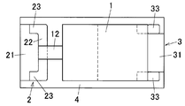
- FIG. 1A is a plan view showing a solid electrolytic capacitor according to an embodiment of the present invention.
- FIG. 1B is a side view showing the solid electrolytic capacitor of the embodiment.
- FIG. 2A is a perspective view showing a developed product for an anode lead terminal used for manufacturing the solid electrolytic capacitor of the embodiment.
- FIG. 2B is a perspective view showing the developed product for an anode lead terminal of the embodiment in a state where a part thereof is pushed and bent.
- FIG. 2C is a perspective view of an anode lead terminal applied to the solid electrolytic capacitor of the embodiment.
- FIG. 3A is a plan view showing the developed product for an anode lead terminal according to the embodiment.
- FIG. 3B is a plan view showing a developed product for cathode lead terminals used for manufacturing the solid electrolytic capacitor of the embodiment.
- FIG. 4 is an enlarged perspective view showing a connecting portion between the anode lead wire and the anode lead terminal in the embodiment.
- FIG. 5 is a side sectional view showing a capacitor element applied to the solid electrolytic capacitor of the embodiment.
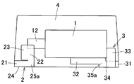
- FIG. 6A is a plan view showing a solid electrolytic capacitor according to a first modification of the present invention.
- FIG. 6B is a side view showing the solid electrolytic capacitor of the first modification.
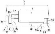
- FIG. 7A is a plan view showing a solid electrolytic capacitor according to a second modification of the present invention.
- FIG. 7B is a side view showing a solid electrolytic capacitor of a second modification.
- FIG. 8 is a plan view showing a modification of the anode lead terminal applicable to the solid electrolytic capacitor of the present invention.
- FIG. 9 is a plan view showing the solid electrolytic capacitor of Comparative Example 1 which is in a comparative relationship with the present invention.
- 10 is a perspective view showing an anode lead terminal applied to the solid electrolytic capacitor of Comparative Example 1.
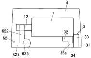
- FIG. 11 is a plan view showing a solid electrolytic capacitor of Comparative Example 2 which is in contrast with the present invention.
- FIG. 12 is a plan view showing a solid electrolytic capacitor of Comparative Example 3 which is in a comparative relationship with the present invention.
- FIG. 1A is a plan view showing a solid electrolytic capacitor according to an embodiment of the present invention
- FIG. 1B is a side view.
- this solid electrolytic capacitor is composed of a capacitor element (1), an anode lead terminal (2), a cathode lead terminal (3), and an exterior sealing body (4).
- the left side is “front side”
- the right side is “rear side”
- the vertical direction is “both sides direction (width direction)”. The description will be made assuming that the vertical direction toward the paper surface is “vertical direction”.
- the capacitor element (1) includes a sintered body (11) of Ta (tantalum) as an anode.
- An anode lead wire (12) is inserted into the sintered body (11) along the axis, and a part (front part) of the lead wire (12) is formed on the sintered body (11). It arrange
- a dielectric layer (13) made of an oxide film, and a semiconductor layer (14) made of a conductive polymer such as polypyrrole.
- the outermost periphery is covered with a cathode layer (15) composed of a carbon paste layer and a silver paste layer.
- the anode lead terminal (2) includes a flat plate-like anode base frame (21) disposed horizontally from the front lower surface to the front of the exterior sealing body (4), and the anode base frame.
- a standing connection piece (22) provided in a vertically rising manner from the rear end edge of the capacitor element (1) and parallel to the front end face of the capacitor element (1), and the standing connection piece (22)
- Both side reinforcing pieces (23) and (23) are provided integrally so as to extend rearward from both side edges and are arranged in parallel to both side surfaces of the exterior sealing body (40).
- the lower surface of the anode base frame (21) is arranged in a state exposed to the outside of the exterior sealing body (4), and is configured as an exposed terminal portion (24).
- the tip edge (upper edge) of the standing connection piece (22) in the anode lead terminal (2) of this configuration is fixed by welding in a state of being in electrical contact with the anode lead wire (12).
- the anode lead terminal (2) is obtained by bending a developed product (blank product 2a) obtained by punching the original plate, as shown in FIGS. 2A and 3A.
- This unfolded product (2a) is an upright stand integrally formed so as to extend rearward at the anode base frame region (21a) corresponding to the anode base frame (21) and the rear edge of the anode base frame region (21a).
- the connecting piece region (22a) and the reinforcing piece regions (23a) and (23a) integrally formed so as to extend on both side edges of the standing connecting piece region (22a) are provided.
- a bent portion (25a) is provided between the anode base frame region (21a) and the standing connection piece region (22a), and at both side edges of the bent portion (25a).
- a rectangular (square) cutout recess (26a) (26a) is formed so that a part of the cutout is cut out.
- the developed product (2a) is bent by the following procedure. First, as shown in FIG. 2B, the reinforcing piece regions (23a) and (23a) of the developed product (2a) are bent 90 ° upward with respect to the standing connection piece region (22a). Thereafter, as shown in FIG. 2C, the standing connection piece region (22a) is bent upward by 90 ° with respect to the anode base frame region (21a) at the bent portion (25a). Thus, the electrode lead terminal (2) having the above-described configuration is produced.
- the reinforcing piece regions (23a) and (23a) are first bent, and then the standing connection piece region (22a) is bent. Therefore, bending can be performed efficiently.
- the reinforcing piece region (23a) is also bent and placed in a vertical state simultaneously with the bending. Therefore, it is necessary to push and bend the vertical reinforcing piece (23a) backward with respect to the standing connection piece (22). That is, when bending the standing connection piece region (22a), it is pushed upward (longitudinal direction), and when bending the reinforcing piece region (23a), it is backward (lateral direction). Will be bent. For this reason, it is necessary to use bending in different directions in the vertical direction and the horizontal direction together, and it may be difficult to perform the bending smoothly.
- the reinforcing piece region (23a) and the standing connection piece region (22a) can be formed only by bending in the upward direction (vertical direction). Can be bent.
- the electrode lead terminal (2) as a bending molded product can be produced by bending the developed product (2a) in only one direction in the vertical direction, and the bending can be efficiently and smoothly performed. And productivity can be improved.
- the manufacturing method such as the manufacturing procedure of the anode lead terminal (2) is not particularly limited, and any manufacturing method may be used.
- the anode lead wire (12) of the capacitor element (1) is connected and fixed to the tip edge (upper edge) of the standing connection piece (22) in the anode lead terminal (2) thus obtained.
- the anode lead wire (12) is fixed to the tip edge of the standing connection piece (22) by spot welding.
- the width of the standing connection piece (22) is as very thin as about 100 ⁇ m, the lead wire welding position of the standing connection piece (22) is recessed during spot welding as shown in FIG.
- the anode lead wire (12) is welded and fixed to the standing connection piece (22) so that the anode lead wire (12) is recessed therein. For this reason, the anode lead wire (12) is firmly connected to the standing connection piece (22) in a stable and stable state.
- the anode lead wire It is possible to effectively prevent 12) from detaching from the standing connection piece (22) and causing a connection failure (open failure).
- the amount of the anode lead wire (12) embedded in the standing connection piece (22) is 2/5 to 3/4 of the outer diameter (diameter) of the anode lead wire (12). . That is, when the amount of sinking is small, there is a high possibility that an open failure will occur. Conversely, if the amount of penetration is too large, connect the lead wire (12) upright. There is a possibility that the pressure applied when joining and fixing to the piece (22) becomes too large, and harmful deformation may occur in the standing connection piece (22) and the peripheral portion.
- the anode lead wire (12) is brought into contact with the standing connection piece (22) in a pressurized state at the time of the spot welding, a stress that deforms the standing connection piece (22) by the pressure contact.
- both-side reinforcing pieces (23) and (23) are formed on both sides of the standing connection piece (22)
- the stress acting on the standing connection piece (22) is It can be reliably received by the anode base plate (21) through the reinforcing pieces (23) and (23). For this reason, it is possible to prevent the standing connection piece (22) from being inadvertently deformed, and when the sealing resin is molded, the anode lead wire (12) is detached from the standing connection piece (22).
- the anode lead wire (12) is fixed to the standing connection piece (22) by spot welding.
- the present invention is not limited to this, and other fixing means such as resistance welding is used in the present invention.
- the anode lead wire (12) may be connected and fixed to the standing connection piece (22) by laser welding, pressure bonding, or the like.
- the cathode lead terminal (3) includes a flat cathode base frame (31) disposed horizontally from the rear lower surface to the rear of the outer sealing body (4) and the lower surface of the capacitor element (1).
- a flat cathode base frame (31) disposed horizontally from the rear lower surface to the rear of the outer sealing body (4) and the lower surface of the capacitor element (1).
- both side guide pieces (33) provided so as to rise upward from both side edges of the cathode base frame (31) and disposed along both sides of the rear end face of the capacitor element (1). 33).
- the lower surface and the rear side portion of the cathode base frame (31) are arranged so as to be exposed to the outside of the exterior sealing body (4), and this exposed portion is configured as an exposed terminal portion (34).
- the upper surface of the flat connection piece (32) in the cathode lead terminal (3) having this structure is bonded and fixed to the lower surface of the capacitor element (1) with an adhesive made of silver paste, and both side guide pieces (33) and (33) are connected to the capacitor element. (1) It is disposed along both sides of the rear end surface.
- the cathode lead terminal (3) is obtained by bending an expanded product (blank product 3a) obtained by punching an original plate.
- the developed product (3a) includes a cathode base frame region (31a) corresponding to the cathode base frame (31), a relay piece region (35a) integrally formed on the front edge of the cathode base frame region (31a), A flat connecting piece region (32a) integrally formed to extend forward to the front end edge of the relay piece region (35a) and a single piece extending to both sides of both side edges of the cathode base frame region (31a).
- notched recesses (36a) (36a) are formed at both side edges of the relay piece region (31a) so as to be partially cut away.
- the guide piece regions (33a) and (33a) on both sides are bent upward and the flat connection piece region (32a) is pushed upward by a predetermined amount so as to push the relay piece region (35a).
- the cathode lead terminal (3) having the above-described configuration is manufactured by bending the front and rear end edges of (2).
- the lower surface of the capacitor element (1) is bonded and fixed to the upper surface of the flat connection piece (22) in the cathode lead terminal (3) thus obtained via an adhesive made of silver paste. At this time, it arrange
- the capacitor element (1) with the lead terminals (2) (3) is made of synthetic resin except for the exposed terminal portions (24) (34) of the lead terminals (2) (3).
- the outer sealing body (4) is formed by coating with the epoxy resin, and a solid electrolytic capacitor is manufactured by this.
- the exposed terminal portions (24) and (34) of the lead terminals (2) and (3) constitute a part of the lead terminals.
- the standing connection piece region (22a) of the developed product for the anode lead terminal (2a) constitutes a portion connected to the edge of the anode base frame
- the reinforcing piece region (23a) is formed of the standing connection piece. It constitutes a portion connected to both side edges.
- deployment product for cathode lead terminals (3a) comprises the part connected with the both-sides edge of the cathode base frame.
- the base frame regions (21a) and (31a) in the developed products for anode and cathode lead terminals (2a) and (3a) are the base frame of the solid electrolytic capacitor as the final product. (21) Although it is longer than (31), this extended portion is appropriately cut as necessary.
- the standing connection piece (22) is formed in a rising shape at the rear end edge of the anode lead terminal (2), and the standing connection piece (22) Since the anode lead wire (12) of the capacitor element (1) is connected to the upper end edge, both can be connected by point contact, the contact area can be reduced, and the capacitor element (1) is installed accordingly. Space can be enlarged and capacity can be increased.
- the reinforcing pieces (23) are provided between the both sides of the standing connection piece (22) in the anode lead terminal (2) and the both sides of the anode base frame (21), Stress acting in the direction of pressing the connecting piece (22) downward can be received by the anode base frame (21) via the reinforcing piece (23), and harmful deformation occurs in the standing connecting piece (22). Can be surely prevented. Therefore, the deformation of the standing connection piece (22) can be reliably prevented against the applied pressure when the anode lead wire (12) is fixed by welding to the standing connection piece (22), and the outer sealing body (4) At the time of formation, it is possible to reliably prevent a connection failure between the standing connection piece (22) and the anode lead wire (12).
- the standing connection piece (22) of the anode lead terminal (2) is formed by bending the standing connection piece region (22a), the standing connection piece is formed by bending.
- the piece (22) can be formed easily.
- the notch recessed part (26a) (26a) is formed in the both-sides edge part in the bending part (25a) between an anode base frame (21) and the standing connection piece (22), in the bending part (25a) Bending can be reliably performed, and the standing connection piece (22) can be reliably formed.
- the reinforcing piece (23) is formed by pressing and bending, the reinforcing piece (23) can be easily formed in the same manner as described above.
- the anode lead terminal (2) is attached to the exterior sealing body by the anchor effect (prevention effect) of the both side reinforcing pieces (23) and (23) with respect to the exterior sealing body (4) as the sealing resin.
- (4) can be firmly fixed in a stable state, and it is possible to reliably prevent the anode lead terminal (2) from being detached from the exterior sealing body (4).
- the anchor of the reinforcing piece (23) can effectively prevent the anode lead terminal (2) from being pulled out and dropped.
- guide pieces (33) and (33) are formed on both side edges of the cathode base frame (31) of the cathode lead terminal (3) in a rising shape, and the guide pieces (33) and (33) are formed. Is disposed along both sides of the rear end face of the capacitor element (1). Therefore, the guide pieces (33) and (33) can prevent displacement of the capacitor element (1) and further improve the quality. it can.
- the cathode lead terminal (3) can be firmly and stably fixed to the exterior sealing body (4) by the anchor effect (prevention effect) of the guide pieces (33) and (33). It is possible to reliably prevent a problem that the cathode lead terminal (3) is detached from the outer sealing body (4).
- the bottom electrode type solid electrolytic capacitor as in the present embodiment, it is possible to effectively prevent the anode lead terminal (3) from being pulled out and dropped by the anchor effect of the guide piece (33).
- the anode lead wire (12) is connected to the upper end of the vertically arranged connection piece (22), and the anode base frame (21) is connected to the lower end of the standing connection piece (22). Because the terminal exposed portion (24) is provided, the lead terminal member is linearly guided from the anode lead wire (12) to the lower end surface of the exterior sealing body (4).
- the wiring shape of the lead terminal member is simplified, so-called electrode routing is reduced, the electrical resistance is reduced, the structure is simplified, and high performance, small size and light weight can be achieved.
- FIGS. 6A and 6B are views showing a solid electrolytic capacitor which is a first modification of the present invention.
- the standing connection piece (22) is formed by bending up at the front end edge of the anode base frame (21) of the anode lead terminal (2), Reinforcing pieces (23) and (23) are formed on both sides of the standing connection piece (22) by pushing and bending.
- the anode lead wire (12) is connected and fixed to the upper end edge of the standing connection piece (22) by spot welding.
- This solid electrolytic capacitor also has the same function and effect as described above.
- FIG. 7A and 7B are views showing a solid electrolytic capacitor which is a second modification of the present invention.
- a terminal exposed portion (24) is formed by bending up at the front edge of the anode base frame (21) of the anode lead terminal (2)
- the cathode A terminal exposed portion (34) is formed by bending up at the rear edge of the cathode base frame (31) of the lead terminal (3).
- anode exposed terminal portions (24) and (24) are formed on the bottom surface and the front end surface of the front end portion of the exterior sealing body (4), and the exterior sealing body (4).
- Cathode-side terminal exposed portions (34) and (34) are provided on the bottom surface and the rear end surface of the rear end portion.
- the terminal exposed portions (24) and (34) of the lead terminals (2) and (3) are arranged on the bottom surface and the front and rear surfaces.
- the present invention is not limited thereto, and in the present invention, You may make it arrange
- the guide piece (33) of the cathode lead terminal (3) is arranged along the rear end face of the capacitor element (1). You may make it arrange
- the reinforcing piece (23) in the anode lead terminal (3) is formed by being bent by 90 ° with respect to the standing connection piece (22). As shown in FIG. 8, the reinforcing piece (23) may be formed to be bent at 90 ° or more with respect to the standing piece (22).
- Example 1 A solid electrolytic capacitor having the same configuration as that of the above embodiment was produced as follows.
- a capacitor element (1) having a length of 0.95 mm, a width of 0.63 mm, a height of 0.53 mm, and an outer diameter ( ⁇ ) of the anode lead wire (12) of 0.15 mm was used. .
- anode lead terminal (2) and the cathode lead terminal (3) for an anode terminal obtained by punching a nickel-plated and tin-plated original plate on a copper alloy plate material having a thickness of 0.1 mm (100 ⁇ m) and A product obtained by bending a developed product for cathode terminals (2a) and (3a) was used.
- the width (A1) of the anode base frame region (21a) is 0.63 mm
- (A31) is set to 0.2 mm
- the length (A32) of the reinforcing piece region (23a) is set to 0.2 mm
- both sides between the anode base frame region (21a) and the standing connection piece region (22a) that is, bending
- rectangular cutout recesses (26) and (26) having a depth (A61) of 0.1 mm and a width (A62) of 0.1 mm are formed.
- the developed product (2a) having this shape was bent in the same manner as in the above embodiment to produce an anode lead terminal (2).
- the cathode lead terminal development product (3a) has a cathode base frame region (31a) width (C1) of 0.43 mm and a flat connection piece region (32a) width (C2) of 0.63 mm.
- the width (C31) of the guide piece region (33a) and the height (C32) of the guide piece region (33a) are set to 0.23 mm, and between the flat connection piece region (32a) and the cathode base frame region (31a).
- rectangular notches (36) and (36) having a depth (C61) of 0.1 mm and a width (C62) of 0.1 mm are formed.
- the developed product (3a) was bent in the same manner as in the above embodiment to produce a cathode lead terminal (3).
- the anode lead wire (12) of the capacitor element (1) is placed on the upper end edge of the standing connection piece (22) in the anode lead terminal (2) having the above structure, and a spot welder (precision resistor manufactured by Himax Co., Ltd.).
- the connection was fixed at a pressure of 4.9 Pa with a welding machine.
- the anode lead wire (12) was sunk into the standing connection piece (22) by about 2/3 with respect to the outer diameter of the lead wire (12).
- the lower electrode layer (35) of the capacitor element (1) was bonded and fixed to the upper surface of the flat connection piece (32) in the cathode lead terminal (3) with a silver paste adhesive.
- the capacitor element with lead terminals thus obtained was set in a predetermined mold, and an epoxy resin was molded in a required region by a transfer molding method to form an exterior sealing body (5). After resin sealing, an aging operation was performed to produce a solid electrolytic capacitor of Example 1 (rated voltage 6.3 V, capacity 15 ⁇ F) having the same configuration as the above embodiment.
- a solid electrolytic capacitor of Comparative Example 1 was produced in substantially the same manner as in Example 1 except that the anode lead terminal (52) having this configuration was used.
- ⁇ Comparative example 2> As shown in FIG. 11, as the anode lead terminal (62), a folded piece (625) is formed on the rear end edge of the anode base frame (621) by folding, and the folded piece (625) is formed on the front end edge. Then, the one in which the standing connection piece (622) was formed by bending up was prepared. In the anode lead terminal (62), the anode lead wire (12) is connected and fixed to the upper end edge of the standing connection piece (622) in the same manner as in the first comparative example.
- a solid electrolytic capacitor of Comparative Example 2 was produced in substantially the same manner as Comparative Example 1 except that the anode lead terminal (62) having this configuration was used.
- ⁇ Comparative Example 3> As shown in FIG. 12, as the anode lead terminal (72), a vertical piece (725) is formed by bending at the front edge of the anode base frame (721), and the upper edge of the standing piece (725). In addition, a plate in which a horizontal connection piece (722) extending rearward by push bending was formed was prepared. In the anode lead terminal (72), the anode lead wire (12) is connected and fixed to the rear portion of the upper surface (flat surface) of the horizontal connection piece (722).
- a fixed electrolytic capacitor of Comparative Example 3 was produced in substantially the same manner as Comparative Example 1 except that the anode lead terminal (72) having this configuration was used.
- the outer sealed body (package 4) becomes larger than that in Example 1 and becomes out of specification. Therefore, the capacitor element (1) having a size (length 0.7 mm, width 0.63 mm, height 0.43 mm) smaller than that of the example or the like was used.
- Example 38 fixed electrolytic capacitors (samples) of Example 1 and Comparative Examples 1 to 3 were prepared. For each sample, capacity, LC (leakage current), ESL (equivalent series inductance), ESR (equivalent series resistance) ) And the number of open defects were measured. The measurement results are shown in Table 1.
- the numerical value of performance is an average value for each sample of Example 1 and Comparative Examples 1 to 3. Furthermore, the capacity, ESR, and ESL were measured by connecting an LCR measuring instrument manufactured by Agilent Technologies to a test fixture manufactured by Almotech.
- ESR is a value at 100 kHz
- ESL is a value at 1 MHz
- LC is a value at 6.3 V, 30 seconds.
- the capacitors other than Comparative Example 3 have the same capacity, ESL, and LC, but in Comparative Example 1, the ESR is deteriorated.
- the surface of the anode lead wire (12) is formed by a natural oxide film or chemical conversion. It shows that the dielectric layer formed cannot be connected with a sufficiently low resistance.
- Comparative Example 2 as in Comparative Example 1, the ESR is worse. This is because when the capacitor element (1) having the same dimensions as in the embodiment is used, the anode lead terminal (62) is formed in an inverted T shape, so that the lead terminal area on the cathode side is limited accordingly. It is considered that the contact area between the anode lead terminal and the capacitor element (1) is reduced, and the resistance is increased. Further, in Comparative Example 2, as in Comparative Example 1, open defects occurred frequently.
- Example 1 related to the present invention, all values of capacity, LC, ESL and ESR are good. Among them, the ESR is good, and the anode lead wire is sufficiently electrically and mechanically connected to the anode REIT terminal. This is because, as in Example 1, when the anode lead wire (12) is spot-welded to the standing connection piece (22) of the anode lead terminal (2), it is formed on the surface of the anode lead wire by the welding. This is because the oxide film and the dielectric layer are surely broken and connected.
- Example 1 Furthermore, in the case of Example 1, no open failure occurred. In the capacitor of the first embodiment, this is because the reinforcing pieces (23) are formed on both sides of the standing connection piece (22) in the anode lead terminal (2), so that the standing connection against the pressing stress acting from above is provided. Since the bending deformation resistance of the piece (22) is improved, it is considered that the occurrence of open defects can be prevented.
- the present invention can be used for a solid electrolytic capacitor in which a capacitor element is sealed with a synthetic resin exterior sealing body.
Abstract
Description
前記陽極リード端子は、前記陽極リード線に対応して、前記外装封止体の下面に沿って配置されている陽極ベースフレームと、前記陽極ベースフレームの端縁から前記コンデンサ素子の前端面に沿って立ち上がり状に配置され、かつ上端縁に前記陽極リード線が接合されている立設接続片と、前記立設接続片の両側縁および前記陽極ベースフレームの両側縁間に設けられている補強片とを備えていることを特徴とする固体電解コンデンサ。 [1] A capacitor element in which an anode lead wire protrudes from the front end surface and a cathode layer is provided on the outer periphery, an anode lead terminal electrically connected to the anode lead wire, and the cathode layer electrically The connected cathode lead terminal is a solid electrolytic capacitor that is sealed by a synthetic resin exterior sealing body except for a part of the anode lead terminal and the cathode lead terminal,
The anode lead terminal corresponds to the anode lead wire, and is disposed along the lower surface of the exterior sealing body. The anode lead terminal extends from the edge of the anode base frame along the front end surface of the capacitor element. And a reinforcing piece provided between both side edges of the standing connection piece and both side edges of the anode base frame. And a solid electrolytic capacitor.
陽極ベースフレームと、その陽極ベースフレームの端縁から立ち上がり状に配置される立設接続片と、前記立設接続片の両側縁および前記陽極ベースフレームの両測縁間に設けられる補強片とを備えた陽極リード端子を準備する工程と、
陰極リード端子を準備する工程と、
前記陽極リード端子を、その陽極ベースフレームを前記コンデンサ素子の前部下方に配置した状態で、前記立設接続片の上端縁に前記陽極リード線を接合固定する工程と、
前記陰極リード端子を前記コンデンサ素子の前記陰極層に接合固定する工程と、
前記両リード端子付きの前記コンデンサ素子を、前記両リード端子の一部を除いて、合成樹脂により被覆成形して、外装封止体を形成する工程とを含むことを特徴とする固体電解コンデンサの製造方法。 [11] A step of preparing a capacitor element in which an anode lead wire protrudes from a front end face and a cathode layer is provided on the outer periphery;
An anode base frame, an upright connection piece arranged in an upright manner from an edge of the anode base frame, and reinforcing pieces provided between both side edges of the upright connection piece and the two edge measurements of the anode base frame Preparing a prepared anode lead terminal;
Preparing a cathode lead terminal;
The anode lead terminal is bonded and fixed to the upper end edge of the standing connection piece in a state where the anode base frame is disposed below the front part of the capacitor element;
Bonding and fixing the cathode lead terminal to the cathode layer of the capacitor element;
A step of forming an outer sealing body by covering and forming the capacitor element with the two lead terminals with a synthetic resin except for a part of the two lead terminals. Production method.
前記陽極リード端子を準備する工程は、前記陽極リード端子用展開製品における前記立設接続片領域を前記陽極ベースフレーム領域に対し押し曲げて、前記立設接続片を形成する工程と、前記陽極リート端子用展開製品における前記補強片領域を前記立設接続片領域に対し押し曲げて、前記補強片を形成する工程とを含む前項11に記載の固体電解コンデンサの製造方法。 [12] An anode base frame region corresponding to the anode base frame, a standing connection piece region connected to an edge of the anode base frame region, and a reinforcement connected to both edges of the standing connection piece region A flat product for an anode lead terminal provided with a single region is prepared in advance,
The step of preparing the anode lead terminal includes the step of forming the standing connection piece by bending the standing connection piece region of the developed product for the anode lead terminal with respect to the anode base frame region, and the anode REIT. The manufacturing method of the solid electrolytic capacitor of the preceding
平坦な形状の陽極ベースフレームと、前記陽極ベースフレームの端縁に立ち上がり状に配置され、かつ前記陽極リード線に接合されている立設接続片と、前記立設接続片の両側縁および前記陽極ベースフレームの両側縁館に設けられている補強片とを備えていることを特徴とする固体電解コンデンサの陽極リード端子。 [15] A solid electrolytic capacitor that is electrically connected to the anode lead wire protruding from the front end face of the capacitor element and is sealed with a synthetic resin exterior sealing body together with the capacitor element except for a part thereof Anode lead terminal,
An anode base frame having a flat shape, an upright connection piece arranged in an upright manner at an edge of the anode base frame and joined to the anode lead wire, both side edges of the upright connection piece and the anode An anode lead terminal for a solid electrolytic capacitor, comprising reinforcing pieces provided at both side edges of the base frame.
上記実施形態と同様な構成の固体電解コンデンサを以下のように作製した。 <Example 1>
A solid electrolytic capacitor having the same configuration as that of the above embodiment was produced as follows.
図9,10に示すように、陽極リード端子(52)として、陽極ベースフレーム(521)の後端縁に、曲げ起こしにより立設接続片(522)が形成されたL字状のものを準備した。この陽極リード端子(52)における立設接続片(522)の上端縁には、コンデンサ素子(1)の陽極リード線(12)を嵌め込んで固定されるV字状ないしU字状の溝(523)を形成した。なお言うまでもなく、この陽極リード端子(52)には、上記実施例1の補強片(23)や切欠凹部(26)と同様なものは形成されていない。 <Comparative Example 1>
As shown in FIGS. 9 and 10, as the anode lead terminal (52), an L-shaped terminal having a standing connection piece (522) formed at the rear end edge of the anode base frame (521) by bending is prepared. did. A V-shaped or U-shaped groove (fitting the anode lead wire (12) of the capacitor element (1) to the upper edge of the standing connection piece (522) in the anode lead terminal (52) (fixed) 523) was formed. Needless to say, the anode lead terminal (52) is not formed with the same thing as the reinforcing piece (23) and the notch recess (26) of the first embodiment.
図11に示すように、陽極リード端子(62)として、陽極ベースフレーム(621)の後端縁に、折り返し加工により折り返し片(625)が形成されるとともに、その折り返し片(625)前端縁に、曲げ起こしにより立設接続片(622)が形成されたものを準備した。この陽極リード端子(62)においては、立設接続片(622)の上端縁に、上記比較例1と同様に、陽極リード線(12)が接続固定されるものである。 <Comparative example 2>
As shown in FIG. 11, as the anode lead terminal (62), a folded piece (625) is formed on the rear end edge of the anode base frame (621) by folding, and the folded piece (625) is formed on the front end edge. Then, the one in which the standing connection piece (622) was formed by bending up was prepared. In the anode lead terminal (62), the anode lead wire (12) is connected and fixed to the upper end edge of the standing connection piece (622) in the same manner as in the first comparative example.
図12に示すように、陽極リード端子(72)として、陽極ベースフレーム(721)の前端縁に、曲げ起こしにより垂直片(725)が形成されるとともに、その立設片(725)の上端縁に、押し曲げ加工により後方に延びる水平接続片(722)が形成されたものを準備した。この陽極リード端子(72)においては、水平接続片(722)の上面(平坦面)後部に、陽極リード線(12)が接続固定されるものである。 <Comparative Example 3>
As shown in FIG. 12, as the anode lead terminal (72), a vertical piece (725) is formed by bending at the front edge of the anode base frame (721), and the upper edge of the standing piece (725). In addition, a plate in which a horizontal connection piece (722) extending rearward by push bending was formed was prepared. In the anode lead terminal (72), the anode lead wire (12) is connected and fixed to the rear portion of the upper surface (flat surface) of the horizontal connection piece (722).

12…陽極リード線
15…陰極層
2…陽極リード端子
2a…陽極リード端子用展開製品
21…陽極ベースフレーム
22…立設接続片
22a…立設接続片領域(連接された部分)
23…補強片
23a…補強片領域(連接された部分)
24…露出端子部
26a…切欠凹部
3…陰極リード端子
31…陰極ベースフレーム
32…平坦接続片
33…ガイド片
33a…ガイド片領域(連接された部分)
4…外装封止体 DESCRIPTION OF
23 ... Reinforcing
24 ... exposed
4 ... exterior sealing body
Claims (16)
- 前端面から陽極リード線が突出し、かつ外周に陰極層が設けられているコンデンサ素子と、前記陽極リード線に電気的に接続されている陽極リード端子と、前記陰極層に電気的に接続されている陰極リード端子とが、前記陽極リード端子および前記陰極リード端子の一部を除いて、合成樹脂製の外装封止体によって封止されている固体電解コンデンサであって、
前記陽極リード端子は、前記陽極リード線に対応して、前記外装封止体の下面に沿って配置されている陽極ベースフレームと、前記陽極ベースフレームの端縁から前記コンデンサ素子の前端面に沿って立ち上がり状に配置され、かつ上端縁に前記陽極リード線が接合されている立設接続片と、前記立設接続片の両側縁および前記陽極ベースフレームの両側縁間に設けられている補強片とを備えていることを特徴とする固体電解コンデンサ。 A capacitor element in which an anode lead wire projects from the front end surface and a cathode layer is provided on the outer periphery, an anode lead terminal electrically connected to the anode lead wire, and an electrical connection to the cathode layer The cathode lead terminal is a solid electrolytic capacitor that is sealed by a synthetic resin exterior sealing body except for a part of the anode lead terminal and the cathode lead terminal,
The anode lead terminal corresponds to the anode lead wire, and is disposed along the lower surface of the exterior sealing body. The anode lead terminal extends from the edge of the anode base frame along the front end surface of the capacitor element. And a reinforcing piece provided between both side edges of the standing connection piece and both side edges of the anode base frame. And a solid electrolytic capacitor. - 前記立設接続片は、前記陽極ベースフレームの端縁に連接されている部分が曲げ起こされて形成されている請求項1に記載の固体電解コンデンサ。 The solid electrolytic capacitor according to claim 1, wherein the standing connection piece is formed by bending a portion connected to an edge of the anode base frame.
- 前記陽極ベースフレームおよび前記立設接続片間の曲折部の両側に、切欠凹部が設けられている請求項2に記載の固体電解コンデンサ。 The solid electrolytic capacitor according to claim 2, wherein a notch recess is provided on both sides of the bent portion between the anode base frame and the standing connection piece.
- 前記補強片は、前記立設接続片の両側縁に連接された部分が折り曲げられて形成されている請求項1~3のいずれか1項に記載の固体電解コンデンサ。 4. The solid electrolytic capacitor according to claim 1, wherein the reinforcing piece is formed by bending portions connected to both side edges of the standing connection piece.
- 前記立設接続片と前記陽極リード線とが溶接によって接合固定されている請求項1~4のいずれか1項に記載の固体電解コンデンサ。 5. The solid electrolytic capacitor according to claim 1, wherein the standing connection piece and the anode lead wire are joined and fixed by welding.
- 前記陽極リード線が、前記立設接続片にめり込んだ状態に固定されている請求項1~5のいずれか1項に記載の固体電解コンデンサ。 The solid electrolytic capacitor according to any one of claims 1 to 5, wherein the anode lead wire is fixed in a state of being embedded in the standing connection piece.
- 前記陽極リード線の前記立設接続片に対するめり込み量が、前記陽極リード線の外径の2/5~3/4である請求項6に記載の固体電解コンデンサ。 The solid electrolytic capacitor according to claim 6, wherein the amount of penetration of the anode lead wire into the standing connection piece is 2/5 to 3/4 of the outer diameter of the anode lead wire.
- 前記陰極リード端子は、前記外装封止体の後部下面に沿って配置されている陰極ベースフレームと、前記コンデンサ素子の下面に接合されている平坦接続片とを備えている請求項1~7のいずれか1項に記載の固体電解コンデンサ。 8. The cathode lead terminal includes a cathode base frame disposed along a rear lower surface of the exterior sealing body, and a flat connection piece bonded to the lower surface of the capacitor element. The solid electrolytic capacitor according to any one of the above.
- 前記陰極リード端子は、前記コンデンサ素子の後端面に沿って立ち上がり状に配置されているガイド片を備えている請求項1~8のいずれか1項に記載の固体電解コンデンサ。 The solid electrolytic capacitor according to any one of claims 1 to 8, wherein the cathode lead terminal includes a guide piece arranged in a rising shape along a rear end surface of the capacitor element.
- 前記ガイド片は、前記陰極ベースフレームの両側縁に連接されている部分が曲げ起こされて形成されている請求項9に記載の固体電解コンデンサ。 10. The solid electrolytic capacitor according to claim 9, wherein the guide piece is formed by bending up portions connected to both side edges of the cathode base frame.
- 前端面から陽極リード線が突出し、かつ外周に陰極層が設けられたコンデンサ素子を準備する工程と、
陽極ベースフレームと、その陽極ベースフレームの端縁から立ち上がり状に配置される立設接続片と、前記立設接続片の両側縁および前記陽極ベースフレームの両測縁間に設けられる補強片とを備えた陽極リード端子を準備する工程と、
陰極リード端子を準備する工程と、
前記陽極リード端子を、その陽極ベースフレームを前記コンデンサ素子の前部下方に配置した状態で、前記立設接続片の上端縁に前記陽極リード線を接合固定する工程と、
前記陰極リード端子を前記コンデンサ素子の前記陰極層に接合固定する工程と、
前記両リード端子付きの前記コンデンサ素子を、前記両リード端子の一部を除いて、合成樹脂により被覆成形して、外装封止体を形成する工程とを含むことを特徴とする固体電解コンデンサの製造方法。 A step of preparing a capacitor element in which an anode lead wire protrudes from the front end surface and a cathode layer is provided on the outer periphery;
An anode base frame, an upright connection piece arranged in an upright manner from an edge of the anode base frame, and reinforcing pieces provided between both side edges of the upright connection piece and the two edge measurements of the anode base frame Preparing a prepared anode lead terminal;
Preparing a cathode lead terminal;
The anode lead terminal is bonded and fixed to the upper end edge of the standing connection piece in a state where the anode base frame is disposed below the front part of the capacitor element;
Bonding and fixing the cathode lead terminal to the cathode layer of the capacitor element;
A step of forming an outer sealing body by covering and forming the capacitor element with the two lead terminals with a synthetic resin except for a part of the two lead terminals. Production method. - 前記陽極ベースフレームに対応する陽極ベースフレーム領域と、前記陽極ベースフレーム領域の端縁に連接された立設接続片領域と、前記立設接続片領域の両測縁に連接された補強片領域とを備えた平板状の陽極リード端子用展開製品を予め準備しておき、
前記陽極リード端子を準備する工程は、前記陽極リード端子用展開製品における前記立設接続片領域を前記陽極ベースフレーム領域に対し押し曲げて、前記立設接続片を形成する工程と、前記陽極リート端子用展開製品における前記補強片領域を前記立設接続片領域に対し押し曲げて、前記補強片を形成する工程とを含む請求項11に記載の固体電解コンデンサの製造方法。 An anode base frame region corresponding to the anode base frame, a standing connection piece region connected to an edge of the anode base frame region, and a reinforcing piece region connected to both measurement edges of the standing connection piece region; Prepare in advance a flat plate-shaped anode lead terminal product with
The step of preparing the anode lead terminal includes the step of forming the standing connection piece by bending the standing connection piece region of the developed product for the anode lead terminal with respect to the anode base frame region, and the anode REIT. The manufacturing method of the solid electrolytic capacitor of Claim 11 including the process of pushing and bending the said reinforcement piece area | region in the expansion | deployment product for terminals with respect to the said standing connection piece area | region. - 前記陽極リード端子を準備する工程において、前記補強片を形成する工程を行った後、前記立設接続片を形成する工程を行うようにした請求項12に記載の固定電解コンデンサの製造方法。 13. The method for manufacturing a fixed electrolytic capacitor according to claim 12, wherein in the step of preparing the anode lead terminal, the step of forming the upright connecting piece is performed after the step of forming the reinforcing piece.
- 前記立設接続片に前記陽極リード線をスポット溶接によって接合固定するようにした請求項11~13のいずれか1項に記載の固体電解コンデンサの製造方法。 The method for producing a solid electrolytic capacitor according to any one of claims 11 to 13, wherein the anode lead wire is joined and fixed to the standing connection piece by spot welding.
- コンデンサ素子の前端面から突出されている陽極リード線に電気的に接続され、一部を除いて、前記コンデンサ素子と共に合成樹脂製の外装封止体によって封止されている固体電解コンデンサの陽極リード端子であって、
平坦な形状の陽極ベースフレームと、前記陽極ベースフレームの端縁に立ち上がり状に配置され、かつ前記陽極リード線に接合されている立設接続片と、前記立設接続片の両側縁および前記陽極ベースフレームの両側縁館に設けられている補強片とを備えていることを特徴とする固体電解コンデンサの陽極リード端子。 The anode lead of the solid electrolytic capacitor that is electrically connected to the anode lead wire protruding from the front end surface of the capacitor element and is sealed with a synthetic resin exterior sealing body together with the capacitor element except for a part thereof A terminal,
An anode base frame having a flat shape, an upright connection piece arranged in an upright manner at an edge of the anode base frame and joined to the anode lead wire, both side edges of the upright connection piece and the anode An anode lead terminal for a solid electrolytic capacitor, comprising reinforcing pieces provided at both side edges of the base frame. - 平坦な形状の陽極ベースフレームと、前記陽極ベースフレームの端縁に立ち上がり状に配置され、かつコンデンサ素子の前端面から突出される前記陽極リード線に接合される立設接続片と、前記立設接続片の両側縁および前記陽極ベースフレームの両側縁館に設けられる補強片とを備えた固体電解コンデンサにおける陽極リード端子の製造方法であって、
前記陽極ベースフレームに対応する陽極ベースフレーム領域と、前記陽極ベースフレーム領域の端縁に連接された立設接続片領域と、前記立設接続片領域の両測縁に連接された補強片領域とを備えた平板状の陽極リード端子用展開製品を製作した後、
前記陽極リード端子用展開製品における前記立設接続片領域を前記陽極ベースフレーム領域に対し押し曲げて、前記立設接続片を形成するとともに、前記陽極リート端子用展開製品における前記補強片領域を前記立設接続片領域に対し押し曲げて、前記補強片を形成するようにしたことを特徴とする固体電解コンデンサにおける陽極リード端子の製造方法。 A flat anode base frame, a standing connection piece that is arranged in a rising shape on an edge of the anode base frame and that is joined to the anode lead wire protruding from the front end surface of the capacitor element, and the standing installation A method for producing an anode lead terminal in a solid electrolytic capacitor comprising both side edges of a connecting piece and reinforcing pieces provided on both side edges of the anode base frame,
An anode base frame region corresponding to the anode base frame, a standing connection piece region connected to an edge of the anode base frame region, and a reinforcing piece region connected to both measurement edges of the standing connection piece region; After producing a flat-plate anode lead terminal product with
The standing connection piece region in the developed product for anode lead terminal is pushed and bent with respect to the anode base frame region to form the standing connection piece, and the reinforcing piece region in the developed product for anode REIT terminal is A method of manufacturing an anode lead terminal in a solid electrolytic capacitor, wherein the reinforcing piece is formed by being pushed and bent with respect to a standing connection piece region.
Priority Applications (4)
| Application Number | Priority Date | Filing Date | Title |
|---|---|---|---|
| JP2010525130A JP4688976B2 (en) | 2008-12-29 | 2009-12-28 | Solid electrolytic capacitor |
| EP09836220.5A EP2372733B1 (en) | 2008-12-29 | 2009-12-28 | Solid electrolytic capacitor |
| US13/142,474 US8614880B2 (en) | 2008-12-29 | 2009-12-28 | Solid electrolytic capacitor including positive and negative electrode lead terminals |
| CN2009801575728A CN102334169B (en) | 2008-12-29 | 2009-12-28 | Solid electrolytic capacitor |
Applications Claiming Priority (2)
| Application Number | Priority Date | Filing Date | Title |
|---|---|---|---|
| JP2008335740 | 2008-12-29 | ||
| JP2008-335740 | 2008-12-29 |
Publications (1)
| Publication Number | Publication Date |
|---|---|
| WO2010076883A1 true WO2010076883A1 (en) | 2010-07-08 |
Family
ID=42309930
Family Applications (1)
| Application Number | Title | Priority Date | Filing Date |
|---|---|---|---|
| PCT/JP2009/071789 WO2010076883A1 (en) | 2008-12-29 | 2009-12-28 | Solid electrolytic capacitor |
Country Status (5)
| Country | Link |
|---|---|
| US (1) | US8614880B2 (en) |
| EP (1) | EP2372733B1 (en) |
| JP (2) | JP4688976B2 (en) |
| CN (1) | CN102334169B (en) |
| WO (1) | WO2010076883A1 (en) |
Cited By (1)
| Publication number | Priority date | Publication date | Assignee | Title |
|---|---|---|---|---|
| JP2012191198A (en) * | 2011-03-11 | 2012-10-04 | Avx Corp | Solid electrolytic capacitor with improved mechanical stability |
Families Citing this family (6)
| Publication number | Priority date | Publication date | Assignee | Title |
|---|---|---|---|---|
| KR101761941B1 (en) * | 2012-08-08 | 2017-08-04 | 삼성전기주식회사 | Tantalum capacitor and method of preparing the same |
| US9640326B2 (en) * | 2012-09-10 | 2017-05-02 | Panasonic Intellectual Property Management Co., Ltd. | Solid electrolytic capacitor |
| JP6087703B2 (en) * | 2013-04-09 | 2017-03-01 | 三洋電機株式会社 | Solid electrolytic capacitor and manufacturing method thereof |
| JP6788492B2 (en) * | 2016-12-21 | 2020-11-25 | 株式会社トーキン | Solid electrolytic capacitors and their manufacturing methods |
| JP6906242B2 (en) * | 2017-02-03 | 2021-07-21 | 日本蓄電器工業株式会社 | Solid electrolytic capacitors and their manufacturing methods |
| JP7213430B2 (en) * | 2017-03-29 | 2023-01-27 | パナソニックIpマネジメント株式会社 | Solid electrolytic capacitor and manufacturing method thereof |
Citations (6)
| Publication number | Priority date | Publication date | Assignee | Title |
|---|---|---|---|---|
| JP2003068576A (en) | 2001-08-30 | 2003-03-07 | Rohm Co Ltd | Structure of surface mounted solid electrolytic capacitor and manufacturing method therefor |
| JP2004055889A (en) | 2002-07-22 | 2004-02-19 | Nec Tokin Corp | Solid electrolytic capacitor |
| JP2004304071A (en) | 2003-03-31 | 2004-10-28 | Sanyo Electric Co Ltd | Solid electrolytic capacitor and its manufacturing method |
| WO2006120779A1 (en) * | 2005-05-13 | 2006-11-16 | Sanyo Electric Co., Ltd. | Stacked type solid electrolytic capacitor and method for manufacturing same |
| JP2008091391A (en) * | 2006-09-29 | 2008-04-17 | Showa Denko Kk | Lead frame member for solid electrolytic capacitor |
| JP2009141209A (en) * | 2007-12-07 | 2009-06-25 | Sanyo Electric Co Ltd | Solid electrolytic capacitor |
Family Cites Families (18)
| Publication number | Priority date | Publication date | Assignee | Title |
|---|---|---|---|---|
| US3550228A (en) * | 1967-11-29 | 1970-12-29 | Jean Claude Asscher | Method of assembling leads to an electrical component and potting same |
| US4247883A (en) * | 1978-07-31 | 1981-01-27 | Sprague Electric Company | Encapsulated capacitor |
| JPS5934625A (en) * | 1982-08-20 | 1984-02-25 | 松尾電機株式会社 | Method of producing chip solid electrolyte condenser |
| GB2141583A (en) * | 1983-06-17 | 1984-12-19 | Standard Telephones Cables Ltd | Leadless capacitors |
| DE3931244A1 (en) * | 1989-09-19 | 1991-03-28 | Siemens Ag | Solid electrolyte capacitor chip - has anode and cathode wires respectively attached to comb plate and attached U=shaped hoop |
| US6625009B2 (en) * | 2001-04-05 | 2003-09-23 | Rohm Co., Ltd. | Solid electrolytic capacitor and method of making the same |
| JP4014819B2 (en) * | 2001-05-14 | 2007-11-28 | Necトーキン株式会社 | Chip capacitor and method of manufacturing the same |
| JP4477287B2 (en) * | 2002-03-15 | 2010-06-09 | Necトーキン株式会社 | Anode terminal plate and chip capacitor manufacturing method |
| JP2004228424A (en) * | 2003-01-24 | 2004-08-12 | Nec Tokin Corp | Chip electrolytic capacitor, and manufacturing method thereof |
| JP4975946B2 (en) * | 2003-09-01 | 2012-07-11 | Necトーキン株式会社 | Chip-type solid electrolytic capacitor and manufacturing method thereof |
| JP4333302B2 (en) * | 2003-09-18 | 2009-09-16 | 日立電線株式会社 | Manufacturing method of lead frame for chip capacitor and chip capacitor |
| JP2005166832A (en) * | 2003-12-01 | 2005-06-23 | Rohm Co Ltd | Solid-state electrolytic capacitor |
| JP2005228801A (en) * | 2004-02-10 | 2005-08-25 | Nec Tokin Corp | Chip-type solid electrolytic capacitor and lead frame used therefor |
| JP4784373B2 (en) * | 2006-04-14 | 2011-10-05 | パナソニック株式会社 | Solid electrolytic capacitor and manufacturing method thereof |
| TWI320191B (en) * | 2006-12-29 | 2010-02-01 | Solid electrolytic capacitor and lead frame thereof | |
| JP4862204B2 (en) * | 2007-12-06 | 2012-01-25 | 三洋電機株式会社 | Solid electrolytic capacitor |
| JP5132374B2 (en) * | 2008-03-18 | 2013-01-30 | 三洋電機株式会社 | Solid electrolytic capacitor and manufacturing method thereof |
| JP5158966B2 (en) * | 2008-10-28 | 2013-03-06 | 三洋電機株式会社 | Solid electrolytic capacitor and manufacturing method thereof |
-
2009
- 2009-12-28 US US13/142,474 patent/US8614880B2/en not_active Expired - Fee Related
- 2009-12-28 EP EP09836220.5A patent/EP2372733B1/en not_active Not-in-force
- 2009-12-28 JP JP2010525130A patent/JP4688976B2/en not_active Expired - Fee Related
- 2009-12-28 WO PCT/JP2009/071789 patent/WO2010076883A1/en active Application Filing
- 2009-12-28 CN CN2009801575728A patent/CN102334169B/en not_active Expired - Fee Related
-
2011
- 2011-02-14 JP JP2011028526A patent/JP5441942B2/en not_active Expired - Fee Related
Patent Citations (6)
| Publication number | Priority date | Publication date | Assignee | Title |
|---|---|---|---|---|
| JP2003068576A (en) | 2001-08-30 | 2003-03-07 | Rohm Co Ltd | Structure of surface mounted solid electrolytic capacitor and manufacturing method therefor |
| JP2004055889A (en) | 2002-07-22 | 2004-02-19 | Nec Tokin Corp | Solid electrolytic capacitor |
| JP2004304071A (en) | 2003-03-31 | 2004-10-28 | Sanyo Electric Co Ltd | Solid electrolytic capacitor and its manufacturing method |
| WO2006120779A1 (en) * | 2005-05-13 | 2006-11-16 | Sanyo Electric Co., Ltd. | Stacked type solid electrolytic capacitor and method for manufacturing same |
| JP2008091391A (en) * | 2006-09-29 | 2008-04-17 | Showa Denko Kk | Lead frame member for solid electrolytic capacitor |
| JP2009141209A (en) * | 2007-12-07 | 2009-06-25 | Sanyo Electric Co Ltd | Solid electrolytic capacitor |
Non-Patent Citations (1)
| Title |
|---|
| See also references of EP2372733A4 |
Cited By (2)
| Publication number | Priority date | Publication date | Assignee | Title |
|---|---|---|---|---|
| JP2012191198A (en) * | 2011-03-11 | 2012-10-04 | Avx Corp | Solid electrolytic capacitor with improved mechanical stability |
| GB2488883B (en) * | 2011-03-11 | 2015-04-08 | Avx Corp | Solid electrolytic capacitor with improved mechanical stability |
Also Published As
| Publication number | Publication date |
|---|---|
| CN102334169B (en) | 2013-04-24 |
| CN102334169A (en) | 2012-01-25 |
| EP2372733B1 (en) | 2018-10-17 |
| EP2372733A4 (en) | 2015-12-09 |
| JP5441942B2 (en) | 2014-03-12 |
| US8614880B2 (en) | 2013-12-24 |
| JP4688976B2 (en) | 2011-05-25 |
| US20110292573A1 (en) | 2011-12-01 |
| EP2372733A1 (en) | 2011-10-05 |
| JPWO2010076883A1 (en) | 2012-06-21 |
| JP2011097111A (en) | 2011-05-12 |
Similar Documents
| Publication | Publication Date | Title |
|---|---|---|
| JP5441942B2 (en) | Solid electrolytic capacitor | |
| JP5040675B2 (en) | Chip-type electronic components | |
| JP2009224627A (en) | Solid-state electrolytic capacitor and its manufacturing method | |
| JP5879491B2 (en) | Solid electrolytic capacitor | |
| US20130182374A1 (en) | Solid electrolytic capacitor and method for producing the same | |
| JP5158966B2 (en) | Solid electrolytic capacitor and manufacturing method thereof | |
| JP2005079357A (en) | Chip type solid electrolytic capacitor, its manufacturing method, and lead frame used therefor | |
| JP5445673B2 (en) | Solid electrolytic capacitor and manufacturing method thereof | |
| JP2010123648A (en) | Electricity accumulation unit | |
| US9595394B2 (en) | Solid electrolytic capacitor, anode lead connection method for the same, and production method for solid electrolytic capacitor | |
| JP2011049225A (en) | Solid electrolytic capacitor | |
| KR102127816B1 (en) | Tantalum capacitor and method of preparing the same | |
| JP4585459B2 (en) | Solid electrolytic capacitor and manufacturing method thereof | |
| JP7328108B2 (en) | Electrolytic capacitor and method for manufacturing electrolytic capacitor | |
| JP2009043749A (en) | Aluminum electrolytic capacitor | |
| JPWO2009013943A1 (en) | Electrolytic capacitor | |
| JP5546919B2 (en) | Solid electrolytic capacitor | |
| JP2018152483A (en) | Capacitor and manufacturing method thereof | |
| US11062852B2 (en) | Solid electrolytic capacitor having an anode terminal and a cathode terminal formed from a single metal plate and method for manufacturing same | |
| JP2007158234A (en) | Chip-type solid electrolytic capacitor | |
| JP2006332403A (en) | Lead frame, manufacturing method of solid electrolytic capacitor of lower-side electrode type employing the same, and solid electrolytic capacitor of lower-side electrode type manufactured by the same | |
| JP5123136B2 (en) | Winding type electrolytic capacitor and manufacturing method thereof | |
| JP2011077079A (en) | Chip-type solid electrolytic capacitor | |
| KR100871035B1 (en) | Lead frame, method of manufacturing a face-down terminal solid electrolytic capacitor using the lead frame, and face-down terminal solid electrolytic capacitor manufactured by the method | |
| JP2011049223A (en) | Solid electrolytic capacitor and method of manufacturing the same |
Legal Events
| Date | Code | Title | Description |
|---|---|---|---|
| WWE | Wipo information: entry into national phase |
Ref document number: 200980157572.8 Country of ref document: CN |
|
| WWE | Wipo information: entry into national phase |
Ref document number: 2010525130 Country of ref document: JP |
|
| 121 | Ep: the epo has been informed by wipo that ep was designated in this application |
Ref document number: 09836220 Country of ref document: EP Kind code of ref document: A1 |
|
| NENP | Non-entry into the national phase |
Ref country code: DE |
|
| WWE | Wipo information: entry into national phase |
Ref document number: 2009836220 Country of ref document: EP |
|
| WWE | Wipo information: entry into national phase |
Ref document number: 13142474 Country of ref document: US |