WO2010073365A1 - 紙葉類識別装置および紙葉類識別方法 - Google Patents
紙葉類識別装置および紙葉類識別方法 Download PDFInfo
- Publication number
- WO2010073365A1 WO2010073365A1 PCT/JP2008/073717 JP2008073717W WO2010073365A1 WO 2010073365 A1 WO2010073365 A1 WO 2010073365A1 JP 2008073717 W JP2008073717 W JP 2008073717W WO 2010073365 A1 WO2010073365 A1 WO 2010073365A1
- Authority
- WO
- WIPO (PCT)
- Prior art keywords
- evaluation value
- paper sheet
- template
- correction data
- channel
- Prior art date
- Legal status (The legal status is an assumption and is not a legal conclusion. Google has not performed a legal analysis and makes no representation as to the accuracy of the status listed.)
- Ceased
Links
Images






Classifications
-
- G—PHYSICS
- G07—CHECKING-DEVICES
- G07D—HANDLING OF COINS OR VALUABLE PAPERS, e.g. TESTING, SORTING BY DENOMINATIONS, COUNTING, DISPENSING, CHANGING OR DEPOSITING
- G07D7/00—Testing specially adapted to determine the identity or genuineness of valuable papers or for segregating those which are unacceptable, e.g. banknotes that are alien to a currency
- G07D7/06—Testing specially adapted to determine the identity or genuineness of valuable papers or for segregating those which are unacceptable, e.g. banknotes that are alien to a currency using wave or particle radiation
- G07D7/12—Visible light, infrared or ultraviolet radiation
-
- G—PHYSICS
- G07—CHECKING-DEVICES
- G07D—HANDLING OF COINS OR VALUABLE PAPERS, e.g. TESTING, SORTING BY DENOMINATIONS, COUNTING, DISPENSING, CHANGING OR DEPOSITING
- G07D7/00—Testing specially adapted to determine the identity or genuineness of valuable papers or for segregating those which are unacceptable, e.g. banknotes that are alien to a currency
- G07D7/20—Testing patterns thereon
- G07D7/202—Testing patterns thereon using pattern matching
- G07D7/206—Matching template patterns
Definitions
- the present invention relates to a paper sheet identification apparatus and a paper sheet identification method for identifying a paper sheet by reading the conveyed paper sheet with an optical line sensor oriented in a direction orthogonal to the conveyance direction, and in particular, per unit time.
- the present invention relates to a paper sheet identification apparatus and a paper sheet identification method capable of improving the number of processed sheets and reducing the size of the apparatus.
- Papers such as banknotes, securities such as checks, forms such as payment slips are transported using a transport mechanism, and papers are identified using an optical line sensor that receives and emits light such as visible light and infrared light.
- a paper sheet identification device is known.
- the optical line sensor performs a data acquisition process for paper sheets in parallel with a blocking process for blocking the pixels of acquired data, and after the scan for the entire paper sheet is completed, the blocking process is performed.
- a technique for performing type determination processing for later data is disclosed.
- Patent Document 1 is merely a technique for performing a blocking process corresponding to a preparation stage for performing the type determination process during scanning of paper sheets, and shortens the time required for the type determination process itself. is not. For this reason, there is a problem that the time required for each sheet of paper cannot be sufficiently shortened.
- the present invention has been made to solve the above-described problems of the prior art, and is capable of improving the number of processed sheets per unit time and reducing the size of the apparatus. It is another object of the present invention to provide a paper sheet identification method.
- the present invention provides a paper sheet identification for identifying the paper sheet by reading the conveyed paper sheet with an optical line sensor oriented in a direction orthogonal to the transport direction.
- a correction data generation unit that generates predetermined correction data by correcting read data obtained by the optical line sensor;
- a storage unit that stores a template defined in advance for each type of paper sheet;
- a first evaluation value that calculates a difference between the correction data up to the first distance and the corresponding area in the template is calculated at a timing when the paper sheet is transported to the first distance. At the timing when the evaluation value calculating means and the paper sheet are transported to a second distance larger than the first distance, the correction data and the tenth data from the first distance to the second distance.
- Extraction means for extracting a candidate template corresponding to the type of the paper sheet from the template based on the first evaluation value and the second evaluation value; and the entire paper sheet by the optical line sensor
- a final discriminating unit that performs final discrimination on the type of the paper sheet based on the candidate template extracted by the extracting unit and the correction data of the entire paper sheet. It is characterized by.
- the extraction unit extracts the template having the smallest overall evaluation value representing the sum of the first evaluation value and the second evaluation value as the candidate template. It is characterized by.
- the present invention is the above invention, wherein the template includes information indicating another template similar to the template, and the extracting means includes information indicating that the extracted candidate template indicates the other template. If it is included, the other template is also extracted as the candidate template.
- the present invention is the above invention, wherein the extraction means uses the other template in which any one of the first evaluation value, the second evaluation value, and the comprehensive evaluation value exceeds a predetermined threshold value. It is excluded from the candidate template.
- the present invention further includes a conveyance direction switching unit that switches the conveyance direction to a normal direction or a reverse direction in the above invention, wherein the correction data generation unit is configured to read data for each line read by the optical line sensor.
- a channel value of each channel composed of a predetermined number of continuous pixels is calculated as an average value of pixel values included in the channel, and the channel value is determined based on whether the transport direction is the forward direction or the reverse direction. The storage order of the channel values is reversed.
- the correction data generation means may convert the channel value stored for the channel into a binarized channel value by comparing it with a binarization threshold value. Based on the binarized channel value, the center position of the paper sheet in the line direction of the optical line sensor is calculated, and the channel value is stored in such a manner that the center position of each line is the same. The skew of the paper sheet is corrected by shifting the channel.
- the correction data generation unit performs the skew correction every time the read data for each line by the optical line sensor reaches a predetermined number of lines of 1 or more.
- the correction data generation means adds the channel value to the data in which the skew is corrected within a block composed of a predetermined number of channels and a predetermined number of lines. And generating the correction data.
- the correction data generation unit may generate the correction data by normalizing all the blocks when all the blocks are prepared for a predetermined area. It is characterized by.
- the final determination unit compares the candidate template extracted by the extraction unit with the correction data of the entire paper sheet for a predetermined feature portion. The final discrimination is performed.
- the present invention is a paper sheet identification method for identifying the paper sheet by reading the conveyed paper sheet with an optical line sensor oriented in a direction orthogonal to the transport direction, the read data by the optical line sensor A correction data generation step for generating predetermined correction data by correcting the data, a storage step for storing a template predefined for each type of the paper sheet in the storage unit, and the paper sheet from the previous position.
- An evaluation value calculating step for calculating an evaluation value obtained by quantifying the difference between the correction data from the previous position to the latest position and the corresponding area in the template each time the sheet is conveyed by a predetermined distance; and the evaluation value calculation
- a candidate template corresponding to the type of the paper sheet is selected from the templates based on the calculated evaluation value.
- the present invention is characterized in that, in the above invention, the extraction step further extracts the candidate template corresponding to the type of the paper sheet from the candidate templates already extracted up to the previous time. .
- predetermined correction data is generated by correcting the read data obtained by the optical line sensor, a template defined in advance for each type of paper sheet is stored, and the paper sheet reaches the first distance.
- a first evaluation value obtained by quantifying the difference between the correction data up to the first distance and the corresponding area in the template is calculated at the transported timing, and the second distance where the paper sheet is larger than the first distance.
- the second evaluation value is calculated by quantifying the difference between the correction data from the first distance to the second distance and the corresponding area in the template at the time when the second evaluation value is conveyed. Then, based on the first evaluation value and the second evaluation value, a candidate template corresponding to the type of paper sheet is extracted from the template, and reading of the entire paper sheet is completed by the optical line sensor.
- the data acquisition process for the paper sheet and the type determination process are performed in parallel.
- the type determination process can be completed when the data acquisition for the entire paper sheet is completed, so that the number of processed sheets per unit time can be improved.
- the distance between the paper sheets and the paper sheets can be reduced, and the conveyance path length can be shortened, so that the apparatus size can be reduced.
- the template having the smallest overall evaluation value representing the sum of the first evaluation value and the second evaluation value (similar to the sheet to be identified) is extracted as a candidate template. Therefore, it is possible to improve the processing speed by simplifying the candidate template extraction process.
- each template includes information indicating another template similar to the own template, and when the extracted candidate template includes information indicating another template, the other template is included. Is also extracted as a candidate template, so that similar templates can be extracted together by performing a process of extracting one template by associating similar templates in advance. Thus, it is possible to achieve both improvement in identification accuracy and reduction in processing time.
- the other template is excluded from the candidate templates.
- the template corresponding to the type of the paper sheet can be selected from the candidate templates by the processing.
- the transport direction is switched between the forward direction and the reverse direction, and the channel value of each channel composed of a predetermined number of continuous pixels is read from the read data for each line by the optical line sensor.
- the transport direction is different because the channel value storage order is reversed for the channel according to whether the transport direction is the forward direction or the reverse direction. Even so, it is possible to make the processing of the acquired data common by making the memory storage state of the acquired data the same.
- the channel value stored for the channel is compared with the threshold value for binarization to be converted into the binarized channel value, and the optical line sensor is converted based on the binarized channel value.
- the center position of the paper sheet in the line direction is calculated, and the skew of the paper sheet is corrected by shifting the channel where the channel value is stored so that the center position of each line is the same. Therefore, there is an effect that the processing speed can be improved by performing the skew correction of the paper sheets without performing complicated image processing such as image rotation processing.
- the skew correction is performed every time the read data for each line by the optical line sensor reaches a predetermined number of lines of 1 or more, so that the skew correction process is performed sequentially. There is an effect that the processing speed can be improved.
- correction data is generated by adding channel values to a block composed of a predetermined number of channels and a predetermined number of lines for the data whose skew has been corrected. It is possible to improve the identification accuracy of paper sheets by removing noise by simple processing.
- the correction data is generated by normalizing all the blocks, so that the paper sheet can be obtained by appropriately performing the normalization process. There is an effect that the accuracy of class identification can be improved.
- the final determination is performed by comparing the extracted candidate template with the correction data of the entire paper sheet for a predetermined feature portion, a plurality of candidate templates are extracted. Even in this case, since one template can be finally selected by simple processing, the processing speed can be improved.
- predetermined correction data is generated by correcting the read data by the optical line sensor, and a template defined in advance for each type of paper sheet is stored in the storage unit.
- an evaluation value is calculated by quantifying the difference between the correction data from the previous position to the latest position and the corresponding area in the template, and a new evaluation value is calculated.
- a candidate template corresponding to the type of paper sheet is extracted from the template based on the calculated evaluation value, and the reading of the entire paper sheet is completed by the optical line sensor, the extracted candidate is extracted.
- Data acquisition for the entire paper sheet is completed because the final determination is made for the paper sheet type based on the template and the correction data for the entire paper sheet. The since it is possible to complete the type determination processing, an effect that it is possible to improve the number of processed per unit time.
- candidate templates corresponding to the type of paper sheet are further extracted from the candidate templates already extracted up to the previous time. Since the number of target candidate templates can be reduced, the processing speed can be improved.
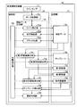
- FIG. 1 is a diagram showing an outline of a paper sheet identification method according to the present invention.
- FIG. 2 is a block diagram illustrating a configuration of the paper sheet identification apparatus.
- FIG. 3 is a diagram illustrating a configuration example of a line sensor and names of banknote orientations.
- FIG. 4 is a diagram illustrating the activation timing of each activation target process.
- FIG. 5 is a diagram showing an outline of the memory storing process.
- FIG. 6 is a diagram showing an outline of the averaging process.
- FIG. 7 is a diagram showing an outline of the skew correction preparation process.
- FIG. 8 is a diagram showing an outline of skew correction processing and blocking processing.
- FIG. 9 is a diagram showing an overview of each evaluation value calculation process.
- FIG. 10 is a diagram showing an outline of exception processing in template extraction.
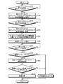
- FIG. 11 is a flowchart illustrating a processing procedure executed by the paper sheet identification apparatus.
- FIG. 12 is a flowchart illustrating a
- FIG. 1 is a diagram showing an outline of a paper sheet identification method according to the present invention.
- an optical line sensor hereinafter simply referred to as “line sensor”
- Identify paper sheets in addition, in the same figure, it has shown about the case where the banknote 100 is conveyed in the direction (longitudinal direction) in which the long side of the banknote 100 becomes parallel to the conveyance direction 1.
- the banknote 100 is divided into, for example, three parts in the longitudinal direction, and the first division area (see “first area” in the figure) and the next division.
- the scan for the area see “second area” in the figure
- a candidate template is extracted, and when the scan for the third area (see the hatched rectangle in the figure) is completed.
- the main feature is that the denomination of the banknote 100 or the direction of the banknote 100 is determined.
- the first evaluation value is calculated based on the scan data of the first area when the banknote 100 passes through the line sensor and the scan for the first area is completed (see (1) in the figure). ).
- the first evaluation value is a value obtained by quantifying the difference between the scan data of the first area and the first area corresponding area in each template.
- the second evaluation value is calculated based on the scan data of the second area (see (2-1) in the figure). Then, a comprehensive evaluation value is calculated based on the first evaluation value and the second evaluation value (see (2-2) in the figure), and a template is extracted based on the calculated comprehensive evaluation value ((2 in the figure)). -3)).
- the paper sheet identification method after dividing the paper sheet to be identified into a plurality of partial areas, narrowing down the template while calculating the evaluation value for each partial area, Since the final determination is made regarding the type and orientation of the paper sheet when the scanning of the entire paper sheet is completed, the determination result can be obtained immediately after the scanning is completed. Therefore, it is possible to shorten the processing time required per sheet.
- FIG. 2 is a block diagram illustrating a configuration of the paper sheet identification device 10.
- FIG. 2 is a block diagram illustrating a configuration of the paper sheet identification device 10.
- only components necessary for explaining the features of the paper sheet identifying apparatus 10 are shown, and descriptions of general components such as a transport mechanism are omitted.
- the paper sheet identification device 10 includes a line sensor 11, a control unit 12, and a storage unit 13. Further, the control unit 12 includes a data acquisition unit 12a, an operation instruction unit 12b, a correction data generation unit 12c, a first evaluation value calculation unit 12d, a second evaluation value calculation unit 12e, and a comprehensive evaluation value calculation unit 12f. A template extraction unit 12g and a final determination unit 12h. The correction data generation unit 12c further includes a one-line correction unit 12ca, a skew correction unit 12cb, and a blocking unit 12cc. .
- storage part 13 memorize
- the first evaluation value 13c, the second evaluation value 13d, and the comprehensive evaluation value 13e are shown separately, but each evaluation value (13c, 13d, and 13e) is 1 It is good also as storing in one table etc. collectively.
- the line sensor 11 is an optical line sensor installed in a direction in which the line direction is orthogonal to the conveyance direction of the banknote 100, and acquires optical data for each line from the banknote 100 by using a light emitting / receiving element. Then, the acquired data is output to the data acquisition unit 12 a of the control unit 12.
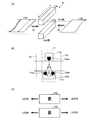
- FIG. 3 is a diagram illustrating a configuration example of the line sensor 11 and names of directions of the banknote 100.
- 1A is a perspective view of the line sensor 11
- FIG. 1B is a cross-sectional view of the line sensor 11, and FIG. Each name is shown.
- the line sensor 11 is composed of an upper unit 11a installed along the upper surface of the conveyance path and a lower unit 11b installed along the lower surface of the conveyance path. Yes.
- the paper sheet identification device 10 corresponds to the switching of the transport direction, and can transport the banknote 100 in either the forward direction 31 or the reverse direction 32.
- the line sensor 11 has N + 1 channels (ch) along the line direction.
- the back side of FIG. 3A is called 0ch (channel) and the near side is called Nch (channel). .
- the width of the line sensor 11 in the line direction is greater than the width of the short side of the banknote 100.
- the upper unit 11a is provided with a light emitting element 11aa that irradiates light to the banknote 100 conveyed through the conveyance path.
- the lower unit 11b includes a light receiving element 11bc that receives the transmitted light transmitted from the light emitting element 11aa of the upper unit 11a by the banknote 100 and receives the reflected light reflected by the banknote 100, and a light emitting element.
- An element 11ba and a light emitting element 11bb are provided.
- the light emitting element 11aa, the light emitting element 11ba, and the light emitting element 11bb are, for example, two light sources in which an element that emits visible light such as green light and an element that emits infrared light are arranged side by side in the transport direction or line direction.
- the light receiving element 11bc receives the transmitted light and reflected light for visible light and the transmitted light and reflected light for infrared light in a time-sharing manner, respectively.
- the timing sensor which detects the approach of the banknote 100 is provided in the position 33 and the position 34 equivalent to the object position centering on the line sensor 11, and the banknote When 100 is transported in the forward direction 31, the timing sensor provided at the position 33 is transported in the reverse direction 32. Detect.
- the light emitting element 11aa is arranged in the upper unit 11a, and the light emitting element 11ba, the light emitting element 11bb, and the light receiving element 11bc are arranged in the lower unit 11b.
- the element 11ba, the light emitting element 11bb, and the light receiving element 11bc may be arranged, and the light emitting element 11aa may be arranged in the lower unit 11b.
- the banknote 100 when the banknote 100 is transported toward the line sensor 11 in the left direction in a state where the surface of the banknote 100 is upright and the pattern is erected, the banknote 100 is transported in the “A direction”. It is expressed.
- the banknote 100 is conveyed toward the line sensor 11 in the right direction in the state where the surface of the banknote 100 is up and the pattern is erected, the banknote 100 is conveyed in the “B direction”. It is expressed. In addition, the direction about the back surface of the banknote 100 is also expressed as “C direction” and “D direction” as shown in FIG.
- control unit 12 When the banknote 100 is scanned by the line sensor 11, the control unit 12 acquires each evaluation value, narrows down candidate templates based on each acquired evaluation value, and when the scan on the banknote 100 is completed. This is a processing unit that immediately performs the final determination of the denomination and direction.
- the operation instruction unit 12b includes a correction data generation unit 12c, a first evaluation value calculation unit 12d, a second evaluation value calculation unit 12e, a comprehensive evaluation value calculation unit 12f, a template extraction unit 12g, and a final determination unit 12h included in the control unit 12. Is a processing unit for instructing the processing start timing.
- a correction data generation unit 12c a correction data generation unit 12c, a first evaluation value calculation unit 12d, a second evaluation value calculation unit 12e, a comprehensive evaluation value calculation unit 12f, a template extraction unit 12g, and a final determination unit 12h included in the control unit 12.
- FIG. 4 is a diagram showing the activation timing of each activation target process.
- the operation instructing unit 12b starts one line correction processing for the one line correction unit 12ca of the correction data generation unit 12c.
- the time interval at which the line sensor 11 acquires data for one line is determined based on a transport speed or a transport distance by a transport mechanism (not shown).
- the operation instructing unit 12b instructs the skew correction unit 12cb to start skew correction processing, and the line sensor 11 acquires data for three lines. Every time it is done, it instructs to start blocking processing by the blocking unit 12cc. The blocking process is executed following the completion of the skew correction process for the third line.
- the operation instruction unit 12b instructs the first evaluation value calculation unit 12d to start the first evaluation value calculation process. Then, when the line sensor 11 acquires 48 lines of data, it instructs the second evaluation value calculation unit 12e to start the second evaluation value calculation process.
- each evaluation value is calculated every time when the scan of the banknote 100 is completed by 1/3. However, every other value such as every 1 ⁇ 2, every 1 ⁇ 4, every 5, etc.
- the evaluation values may be calculated at equal intervals. Note that each evaluation value may be calculated not at equal intervals but at unequal intervals.
- the operation instruction unit 12b instructs the comprehensive evaluation value calculation unit 12f to start the comprehensive evaluation value calculation process, and the comprehensive evaluation value
- the template extraction unit 12g is instructed to start the template extraction process.
- the final determination unit 12h is instructed to start the final determination process.
- the operation instructing unit 12b performs correction data generation processing for each small number of lines (for example, one line or three lines), evaluation value calculation processing that is performed each time scanning is completed about 1/3, and scanning is about 2 / 3 Controls the start timing of the comprehensive evaluation value calculation process and the template extraction process performed when completed, and the final determination process performed when all the scans are completed.
- the correction data generation unit 12c is a processing unit that performs scan data correction processing performed for each small number of lines (for example, one line or three lines), and includes a one-line correction unit 12ca, a skew correction unit 12cb, and blocking. Part 12cc.
- the one-line correction unit 12ca is a processing unit that performs correction processing on the data for one line acquired by the line sensor 11, and performs processing for storing the data after one-line correction in the storage unit 13 as the correction data 13a.
- the one-line correction unit 12ca also performs a skew correction preparation process for generating skew correction preparation data used in advance by a skew correction unit 12cb described later.
- the processing contents executed by the one-line correction unit 12ca will be described with reference to FIGS.
- FIG. 5 is a diagram showing an outline of the memory storing process. Note that (A) in the figure shows a case where the banknote 100 is conveyed in the forward direction (see 31 in FIG. 3), and (B) in the figure shows the banknote 100 in the reverse direction (see 32 in FIG. 3). ) Are shown respectively. Moreover, in the same figure, it has shown about the case where the banknote 100 is conveyed to A direction (refer (C) of FIG. 3) about both (A) and (B).
- the memory storage image by the one-line correction unit 12ca is as shown in FIG.
- the one-line correction unit 12ca reverses the channel of the memory storage image (see (A-1) in the figure) (see (A-2 in the figure)). )), And an inverted image (see (A-3) in the figure) is generated.
- the image stored in the memory by the one-line correction unit 12ca is as shown in FIG.
- the image stored in the memory in the reverse conveyance (see (B-1) in the figure) is the same as the reverse image in the normal conveyance (see (A-3) in the figure).
- the one-line correction unit 12ca controls the memory storage position so that the same memory storage image is obtained regardless of whether the transport direction is the forward direction or the reverse direction.
- FIG. 6 is a diagram showing an outline of the averaging process.
- FIG. 6 shows an outline of the averaging process performed in combination with the channel inversion process shown in FIG. 5 (see (A-2) in FIG. 5).
- the data for one line acquired by the line sensor 11 are represented as a set of pixels.
- the one-line correction unit 12ca calculates an average value for pixel values of continuous eight pixels, and stores the calculated average value in a memory area corresponding to each channel.
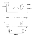
- FIG. 7 is a diagram showing an outline of the skew correction preparation process.
- a binarization process for binarizing the channel value stored in each channel, a section where the banknote 100 exists in one line of data is detected, and the sheet width (of the line sensor 11) is detected.
- a center channel position calculation process is performed to calculate the center channel position based on the calculated paper sheet width.
- a graph 71 representing each channel value is obtained when the horizontal axis is the channel (ch) and the vertical axis is the channel value.
- the graph 71 exceeds a predetermined binarization threshold, “no paper sheet” is set to “0”, and when the graph 71 is equal to or less than the predetermined binarization threshold, “paper sheet is present”.
- a binarized channel value is obtained.
- FIG. 7B shows the binarized channel values obtained in this way.
- the left end detection, right end detection, and hole detection shown in FIG. 7C are performed using such binarized channel values (see FIG. 7B).
- the left end 74 is detected as the direction of the arrow shown in FIG. 7C, that is, the channel number that first becomes “1” from 0ch to Nch.
- the right end 75 is detected as the direction of the arrow shown in FIG. 7C, that is, the channel number that finally becomes “1” from 0ch to Nch. In the case shown in the figure, the position of the right end 75 is “N ⁇ 2” ch. Note that a channel whose binarized channel value is “0” in the section from the left end 74 to the right end 75 is detected as a hole 73.
- the hole 73 corresponds to 72 shown in FIG.
- the sheet width is calculated as a value obtained by adding 1 to the value obtained by subtracting the channel number of the left end 74 from the channel number of the right end 75.
- the center channel position described with reference to FIG. 7 is used when the skew correction unit 12cb performs the skew correction processing. This point will be described later with reference to FIG.
- the skew correction unit 12cb is a processing unit that is activated by an instruction from the operation instruction unit 12b at every timing when the correction data 13a for three lines is prepared, and performs a simple skew correction process of the correction data 13a. is there.
- the skew means that the direction of the long side of the banknote 100 is deviated from the transport direction
- the skew correction means a correction process in which the direction of the long side on the image data is parallel to the transport direction. Point to.
- the skew correction unit 12cb may be activated at every timing when the correction data 13a for n lines (n is an integer of 1 or more) is prepared.
- the blocking unit 12cc is activated by an instruction from the operation instruction unit 12b every time the skew correction process by the skew correction unit 12cb is completed, and performs a process of collecting data for a predetermined line ⁇ predetermined channel as one block. It is a processing unit.
- FIG. 8 is a diagram showing an outline of skew correction processing and blocking processing.
- FIG. 3A shows the state before skew correction
- FIG. 2B shows the state after skew correction
- FIG. 3C shows an example of blocking processing. Respectively.
- the hatched area 81 in the figure corresponds to the left end 74 to the right end 75 in FIG. 7 (3)
- the black rectangle 82 corresponds to the above-mentioned center channel position.
- the center channel position is shifted in the channel (ch) direction.
- the skew correction unit 12cb performs correction to shift each channel position that is a channel value storage destination so that the center channel position is aligned in the channel (ch) direction. In this way, skew can be corrected as shown in FIG.
- the blocking unit 12cc calculates a block value by adding each channel value (channel value) to a block composed of a predetermined line and a predetermined channel.
- channel value channel value
- the skew correction unit 12cb executes the skew correction process every several lines, for example, every three lines.
- the blocking unit 12cc executes the blocking process every time the skew correction process by the skew correction unit 12cb is completed.
- the block forming unit 12cc calculates the block value of one area
- the average value of the block values in the corresponding area is equal to a predetermined reference value
- a curve connecting each block value and a predetermined reference Normalization processing is performed to correct each block value so that the area between the values is constant.
- the sum value is obtained by adding the absolute value of the difference between each block value and the average value within the area, and the ratio between the obtained sum value and a predetermined value is calculated.
- the difference between each block value and the average value is multiplied by the ratio, and the normalized block value is added by adding values adjusted so that the average value after multiplying the ratio becomes equal to a predetermined reference value.
- the first evaluation value calculation unit 12d is activated by an instruction from the operation instruction unit 12b when, for example, the scan for the banknote 100 is completed about 1/3, and in the first area shown in FIG. 1 and each template 13b. It is a processing unit that performs a process of calculating the first evaluation value 13c by comparing the area corresponding to the first area and storing the calculated first evaluation value 13c in the storage unit 13.
- the second evaluation value calculation unit 12e is activated by an instruction from the operation instruction unit 12b when, for example, the scan on the banknote 100 is completed about 2/3, and the second area shown in FIG. It is a processing unit that performs a process of calculating the second evaluation value 13d by comparing the area corresponding to the second area in 13b and storing the calculated second evaluation value 13d in the storage unit 13.
- the comprehensive evaluation value calculation unit 12f is activated by an instruction from the operation instruction unit 12b, and the first evaluation value 13c and the second evaluation value 13d are obtained.
- the processing unit performs a process of calculating the comprehensive evaluation value 13e by adding up the templates 13b.
- the comprehensive evaluation value calculation unit 12f also performs a process of storing the calculated comprehensive evaluation value 13e in the storage unit 13.
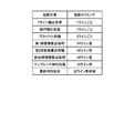
- FIG. 9 is a diagram showing an overview of each evaluation value calculation process.
- the first evaluation value calculation unit 12d compares the first area of the correction data 13a with the first area of each template 13b.
- the second evaluation value calculation unit 12e compares the second area of the correction data 13a with the second area of each template 13b.
- the first evaluation value calculation unit 12d calculates a first evaluation value 13c for each pattern representing the type of the template 13b.
- the first evaluation value 13c is obtained by quantifying the difference between the correction data 13 to be compared and the template 13b.
- the first evaluation value 13c is a value obtained by adding the difference between the block values of the corresponding blocks.
- the second evaluation value calculation unit 12e also calculates the second evaluation value by the same method as the first evaluation value calculation unit 12d.
- the comprehensive evaluation value calculation unit 12f calculates the comprehensive evaluation value 13e by adding the first evaluation value 13c and the second evaluation value 13d for each type of template (for each denomination / direction). For example, as illustrated in FIG. 9B, the comprehensive evaluation value calculation unit 12 f adds the first evaluation value 13 c and the second evaluation value 13 d for the template 13 b of the pattern 1, thereby A comprehensive evaluation value 13e for the template 13b is calculated. In this way, the comprehensive evaluation value 13e is calculated for all the templates 13b.
- the template extraction unit 12g is a processing unit that performs a process of extracting one or a plurality of candidate templates from the template 13b based on the total evaluation value 13e calculated by the total evaluation value calculation unit 12f. Specifically, the template extraction unit 12g extracts the template 13b having the smallest overall evaluation value 13e as a candidate template.
- each template 13b includes information indicating another template similar to the “own template” (hereinafter referred to as “similar template”). Then, when the template 13b having the smallest comprehensive evaluation value 13e includes information indicating “similar template”, the template extracting unit 12g extracts the “similar template” as a candidate template.
- the candidate template 13b having the smallest comprehensive evaluation value 13e does not include information indicating “similar template”, the candidate template is narrowed down to one at this stage.
- the template extracting unit 12g extracts the “similar template” as a candidate template.
- exception processing to be excluded from the candidate template is also performed.
- exception processing performed by the template extraction unit 12g will be described with reference to FIG.
- FIG. 10 is a diagram showing an outline of exception processing in template extraction.
- the template extraction unit 12g uses the first evaluation value 13c as the predetermined first evaluation value threshold value and the second evaluation value for the “similar template” indicated by the template 13b having the smallest overall evaluation value 13e. 13d is compared with a predetermined second evaluation value threshold, and the comprehensive evaluation value 13e is compared with a predetermined comprehensive evaluation value. If there is even one evaluation value that exceeds the threshold, the corresponding “similar template” is excluded from the candidate templates.
- the above-described exception processing is executed for the templates 13b of “Pattern 4” and “Pattern 5”. If the “pattern 4” template 13b matches the exception processing conditions, the “pattern 4” template 13b is excluded from the candidate templates. Then, the templates 13b of “Pattern 2” and “Pattern 5” are passed to the final determination unit 12h as candidate templates.
- the final discriminating unit 12h is based on one or more candidate templates extracted by the template extracting unit 12g and the correction data 13a for the entire banknote 100, as shown in the final denomination and direction (shown in FIG. 3C). Further, it is a processing unit that performs processing for determining “A direction”, “B direction”, “C direction”, and “D direction”.
- the final determination unit 12h performs an auxiliary determination process of applying one or more determination formulas for each pattern of the candidate template and inspecting the validity of the candidate template with respect to the predetermined part (the characteristic part in the banknote 100) of the correction data 13a. . Then, candidate templates that are determined to be invalid by one of the determination formulas are excluded, and if one candidate template is finally left, the denomination and direction corresponding to this candidate template are set as the final determination result.
- the banknote 100 is handled as a reject banknote, assuming that the denomination and the direction cannot be determined.
- the storage unit 13 is a storage unit configured by a storage device such as a nonvolatile memory or a hard disk drive, and includes correction data 13a, a template 13b, a first evaluation value 13c, a second evaluation value 13d, and a comprehensive evaluation value 13e. And remember.
- the correction data 13a and each evaluation value may be written in the volatile memory.
- the correction data 13a is data generated by the correction data generation unit 12c, and becomes the block data (see 83 in FIG. 8) for the entire banknote 100 when the scan for the entire banknote 100 is completed.
- the template 13b is prepared for each combination pattern of the denomination and direction of the banknote 100 (see “A direction”, “B direction”, “C direction”, and “D direction” shown in FIG. 3C). Data for discrimination. Since the first evaluation value 13c, the second evaluation value 13d, and the comprehensive evaluation value 13e have already been described with reference to FIG. 9 and the like, description thereof is omitted here.
- FIG. 11 is a flowchart illustrating a processing procedure executed by the paper sheet identification apparatus 10.
- the operation instruction unit 12b determines whether or not the generation of the correction data 13a for the first area is completed by the correction data generation unit 12c (step S101), and the correction data 13a for the first area is determined.
- step S101 Yes
- step S101 Yes
- step S101 Yes
- step S101 Yes
- step S101 Yes
- step S101 Yes
- an operation instruction is given to the first evaluation value calculation unit 12d. If the determination condition in step S101 is not satisfied (step S101, No), the process in step S101 is repeated.
- the first evaluation value calculation unit 12d calculates the first evaluation value 13c for each template by performing matching with all templates for the first area, and stores the calculated first evaluation value 13c in the storage unit 13. (Step S102). Subsequently, the operation instructing unit 12b determines whether or not the generation of the correction data 13a for the second area has been completed by the correction data generation unit 12c (step S103), and the generation of the correction data 13a for the second area has been completed. In such a case (step S103, Yes), an operation instruction is given to the second evaluation value calculation unit 12e. If the determination condition in step S103 is not satisfied (step S103, No), the process in step S103 is repeated.
- the second evaluation value calculation unit 12e calculates the second evaluation value 13d for each template by performing matching with all templates for the second area, and stores the calculated second evaluation value 13d in the storage unit 13.
- the comprehensive evaluation value calculation unit 12f calculates the comprehensive evaluation value 13e by adding the first evaluation value 13c and the second evaluation value 13d for each template (denomination / direction) and the calculated comprehensive evaluation.
- the value 13e is stored in the storage unit 13 (step S105), and the template extraction unit 12g extracts a candidate template that is closest to the paper sheet to be identified based on the comprehensive evaluation value 13e (step S106).
- the operation instruction unit 12b determines whether the correction data generation unit 12c has completed the generation of the correction data 13a for all areas (step S107), and when the generation of the correction data 13a for all areas has been completed. (Step S107, Yes), an operation instruction is given to the final determination unit 12h. In addition, when the determination condition of step S107 is not satisfied (step S107, No), the process of step S107 is repeated.
- the final determination unit 12h determines whether or not at least one candidate template exists (step S108). If there is a candidate template (step S108, Yes), the correction data 13a for all areas is supported. A determination process is performed (step S109). Then, it is determined whether or not the candidate template (denomination / direction) is narrowed down to one (step S110). If the candidate template is narrowed down to one (step S110, Yes), the denomination is determined. (Step S111), and the process is terminated.
- step S108 determines whether there is no corresponding denomination (step S112), and the process is performed. finish.
- the denomination is determined, but not only the denomination but also the direction of the banknote 100 (four directions shown in FIG. 3C, that is, “A direction”, “B direction”). , “C direction” and “D direction”).
- step S104 the template matching when calculating the second evaluation value for the second area is performed for templates corresponding to all denominations and directions. It is good also as limiting to the template whose 1 evaluation value became below predetermined value. By doing in this way, the processing time of a 2nd evaluation value calculation process can be shortened. In this case, since the second evaluation value (the n-1th evaluation value when all areas are divided into n) can be used as the comprehensive evaluation value in step S105, the processing of the comprehensive evaluation value calculation process Time can be shortened.
- FIG. 12 is a flowchart illustrating a processing procedure of candidate template extraction processing.
- the template extraction unit 12g extracts a template 13b having the smallest comprehensive evaluation value 13e as a candidate template (step S201).
- step S202 it is determined whether or not a similar template is specified in the extracted candidate template. If a similar template is specified (step S202, Yes), the similar template is added to the candidate template (step S202). Step S203). If the determination condition in step S202 is not satisfied (No in step S202), the process proceeds to step S204 without performing the process in step S203.
- the template extraction unit 12g determines whether any of the first evaluation value 13c, the second evaluation value 13d, or the comprehensive evaluation value 13e is greater than a predetermined threshold for the candidate template (step S204).
- step S204 If any of the evaluation values is larger than the predetermined threshold (step S204, Yes), the corresponding template is excluded from the candidate templates (step S205). If the determination condition in step S204 is not satisfied (No in step S204), the process proceeds to step S206 without performing the process in step S205.
- step S206 it is determined whether or not there is a next candidate template. If there is a next candidate template (step S206, Yes), the next candidate template is set as a target template (step S207). ), And repeats the processing from step S204.
- step S208 the candidate template is output (step S208), and the process is terminated.
- the candidate template is output (step S208), and the process is terminated.
- the final determination result is the denomination, orientation, and front / back of the candidate template output in step S208.
- the correction data generation unit generates predetermined correction data by correcting the read data by the optical line sensor, and the storage unit is defined in advance for each type of paper sheet.
- the first evaluation value calculation unit quantifies the difference between the correction data up to the first distance and the corresponding area in the template at the timing when the paper sheet is conveyed to the first distance.
- the second evaluation value calculation unit corrects from the first distance to the second distance.
- the template extraction unit performs the first evaluation value and the second evaluation value.
- the final discriminating unit determines the extracted candidate template and the correction data of the entire paper sheet. Based on the above, the paper sheet identification device is configured to make a final determination on the type of paper sheet.
- the type determination process can be completed when data acquisition for the entire paper sheet is completed.
- the number of processed sheets can be improved.
- the distance between the paper sheets and the paper sheets can be reduced, and the conveyance path length can be shortened. Therefore, the apparatus size can be reduced.
- the present invention when the second evaluation value is calculated, a comprehensive evaluation value based on the first evaluation value and the second evaluation value is calculated, and a candidate template is extracted based on the calculated comprehensive evaluation value.
- the present invention is not limited to this, and the candidate templates may be narrowed down based on the first evaluation value when the first evaluation value is calculated. By doing so, the number of candidate templates to be processed can be reduced, so that the processing speed can be further improved.
- the number of divisions may be any number.
- n is an integer of 1 or more
- final candidate templates should be narrowed down until the evaluation value for the (n ⁇ 1) th area is calculated. That's fine.
- the candidate templates may be narrowed down to finally determine one candidate template.
- the division number (n) is large, it is possible to determine the denomination / direction before calculating the (n-1) th evaluation value, that is, the (n-2) th or less.
- the paper sheet identification apparatus and the paper sheet identification method according to the present invention are useful for paper sheet identification, particularly when it is desired to improve the number of processed sheets per unit time or the size of the apparatus. Suitable for miniaturization.
Landscapes
- Physics & Mathematics (AREA)
- General Physics & Mathematics (AREA)
- Health & Medical Sciences (AREA)
- General Health & Medical Sciences (AREA)
- Toxicology (AREA)
- Engineering & Computer Science (AREA)
- Computer Vision & Pattern Recognition (AREA)
- Inspection Of Paper Currency And Valuable Securities (AREA)
Abstract
補正データ生成部が、光学ラインセンサによる読取データを補正することで所定の補正データを生成し、記憶部が、紙葉類の種別ごとに予め定義されたテンプレートを記憶し、紙葉類が第1の距離まで搬送されたタイミングで、第1評価値算出部が、第1の評価値を算出し、紙葉類が第1の距離よりも大きい第2の距離まで搬送されたタイミングで、第2評価値算出部が、第2の評価値を算出し、テンプレート抽出部が、第1の評価値および第2の評価値に基づいてテンプレートの中から紙葉類の種別に対応する候補テンプレートを抽出し、光学ラインセンサによって紙葉類の全体について読み取りが完了したならば、最終判別部が、抽出された候補テンプレートおよび紙葉類全体の補正データに基づいて紙葉類の種別について最終判別を行うように紙葉類識別装置を構成する。
Description
本発明は、搬送される紙葉類を搬送方向と直交する向きの光学ラインセンサで読み取ることで紙葉類を識別する紙葉類識別装置および紙葉類識別方法に関し、特に、単位時間あたりの処理枚数を向上させることができるとともに、装置サイズの小型化を図ることができる紙葉類識別装置および紙葉類識別方法に関する。
搬送機構を用いて紙幣、小切手などの有価証券、納付書などの帳票類といった紙葉類を搬送し、可視光線や赤外線等の光を受発光する光学ラインセンサを用いて紙葉類を識別する紙葉類識別装置が知られている。
このような光学ラインセンサを用いて紙葉類の識別処理を行う場合、紙葉類全体に対するスキャン完了後に、紙葉類全体についての画像データを用いて種別判別処理を行うことが一般的である。
このため、紙葉類を連続して識別する場合には、種別判別処理が完了するまでは次の紙葉類に対する識別処理を開始できない。したがって、紙葉長と種別判別処理中の搬送距離とを足し合わせた長さの搬送路を必要とするので、紙葉類を搬送する搬送路を長めに確保したり、連続して搬送される紙葉類と紙葉類との間隔を長めにしたり、といった対策が必要であった。
しかし、上記した対策をとると、装置サイズの肥大化や、単位時間あたりの処理枚数(処理スピード)の伸び悩みといった不都合が生じする。このため、紙葉類全体に対するスキャン完了後に行われる種別判別処理に要する時間を短縮しようとする試みがなされている。
たとえば、特許文献1には、光学ラインセンサが紙葉類に対するデータ取得処理と、取得データの画素をブロック化するブロッキング処理とを並行して行い、紙葉類全体に対するスキャン完了後には、ブロッキング処理後のデータに対する種別判別処理を行う技術が開示されている。
しかしながら、特許文献1の技術は、種別判別処理を行ううえでの準備段階に相当するブロッキング処理を紙葉類のスキャン中に行う技術にすぎず、種別判別処理自体の所要時間を短縮化するものではない。このため、紙葉類1枚あたりに要する時間を十分に短縮することができないという問題があった。
また、紙葉類のスキャン後に確保すべき処理時間が長いことから、データ取得中の紙葉類と次の紙葉類との間隔をあける必要があり、搬送路を長めに確保する必要性があるという問題もあった。特に、紙葉類を長手方向に搬送する紙葉類識別装置の場合には、短手方向に搬送する場合よりも搬送路を長くする必要があるため、搬送路長の確保による装置サイズの肥大化が顕著となってしまう。
これらのことから、単位時間あたりの処理枚数を向上させることができるとともに、装置サイズの小型化を図ることができる紙葉類識別装置あるいは紙葉類識別方法をいかにして実現するかが大きな課題となっている。なお、かかる課題は、紙葉類の搬送方向を正逆方向に切り替える紙葉類識別装置についても同様に発生する課題である。
本発明は、上述した従来技術の課題を解決するためになされたものであり、単位時間あたりの処理枚数を向上させることができるとともに、装置サイズの小型化を図ることができる紙葉類識別装置および紙葉類識別方法を提供することを目的とする。
上述した課題を解決し、目的を達成するために、本発明は、搬送される紙葉類を搬送方向と直交する向きの光学ラインセンサで読み取ることで前記紙葉類を識別する紙葉類識別装置であって、前記光学ラインセンサによる読取データを補正することで所定の補正データを生成する補正データ生成手段と、前記紙葉類の種別ごとに予め定義されたテンプレートを記憶する記憶手段と、前記紙葉類が第1の距離まで搬送されたタイミングで、前記第1の距離までの前記補正データと前記テンプレートにおける対応領域との差異を数値化した第1の評価値を算出する第1の評価値算出手段と、前記紙葉類が前記第1の距離よりも大きい第2の距離まで搬送されたタイミングで、前記第1の距離から前記第2の距離までの前記補正データと前記テンプレートにおける対応領域との差異を数値化した第2の評価値を算出する第2の評価値算出手段と、前記第2の評価値算出手段によって前記第2の評価値が算出されたならば、前記第1の評価値および前記第2の評価値に基づいて前記テンプレートの中から当該紙葉類の種別に対応する候補テンプレートを抽出する抽出手段と、前記光学ラインセンサによって前記紙葉類の全体について読み取りが完了したならば、前記抽出手段によって抽出された前記候補テンプレートおよび当該紙葉類全体の前記補正データに基づいて当該紙葉類の種別について最終判別を行う最終判別手段とを備えたことを特徴とする。
また、本発明は、上記の発明において、前記抽出手段は、前記第1の評価値と前記第2の評価値との和をあらわす総合評価値が最も小さい前記テンプレートを前記候補テンプレートとして抽出することを特徴とする。
また、本発明は、上記の発明において、前記テンプレートは、当該テンプレートと類似する他のテンプレートを指し示す情報を含んでおり、前記抽出手段は、抽出した前記候補テンプレートが前記他のテンプレートを指し示す情報を含んでいる場合には、当該他のテンプレートについても前記候補テンプレートとして抽出することを特徴とする。
また、本発明は、上記の発明において、前記抽出手段は、前記第1の評価値、前記第2の評価値あるいは前記総合評価値のうちいずれかが所定の閾値を上回った前記他のテンプレートを前記候補テンプレートから除外することを特徴とする。
また、本発明は、上記の発明において、前記搬送方向を正方向または逆方向へ切り替える搬送方向切替手段をさらに備え、前記補正データ生成手段は、前記光学ラインセンサによる1ラインごとの読取データについて、所定数の連続画素からなる各チャンネルのチャンネル値を当該チャンネルに含まれる画素値の平均値として算出し、前記搬送方向が前記正方向であるか前記逆方向であるかに応じて前記チャンネルに対して前記チャンネル値の格納順序を逆転させることを特徴とする。
また、本発明は、上記の発明において、前記補正データ生成手段は、前記チャンネルに対して格納された前記チャンネル値を2値化用閾値と比較することで2値化チャンネル値へ変換したうえで前記2値化チャンネル値に基づいて前記光学ラインセンサのライン方向における前記紙葉類の中心位置を算出し、前記ラインごとの前記中心位置が同一となるように前記チャンネル値の格納先となる前記チャンネルをシフトすることで前記紙葉類の斜行を補正することを特徴とする。
また、本発明は、上記の発明において、前記補正データ生成手段は、前記光学ラインセンサによる1ラインごとの読取データが1以上の所定ライン数に達するごとに前記斜行の補正を行うことを特徴とする。
また、本発明は、上記の発明において、前記補正データ生成手段は、前記斜行が補正されたデータについて、前記チャンネル値を、所定数のチャンネルおよび所定数のラインからなるブロック内で加算することで前記補正データを生成することを特徴とする。
また、本発明は、上記の発明において、前記補正データ生成手段は、所定の領域についてすべての前記ブロックが揃った場合に、前記すべての前記ブロックを正規化することで前記補正データを生成することを特徴とする。
また、本発明は、上記の発明において、前記最終判別手段は、所定の特徴部位について、前記抽出手段によって抽出された前記候補テンプレートと前記紙葉類全体の前記補正データとを対比することで、前記最終判別を行うことを特徴とする。
また、本発明は、搬送される紙葉類を搬送方向と直交する向きの光学ラインセンサで読み取ることで前記紙葉類を識別する紙葉類識別方法であって、前記光学ラインセンサによる読取データを補正することで所定の補正データを生成する補正データ生成工程と、前記紙葉類の種別ごとに予め定義されたテンプレートを記憶部へ記憶させる記憶工程と、前記紙葉類が前回の位置から所定距離だけ搬送されるたびに、前記前回の位置から最新の位置までの前記補正データと前記テンプレートにおける対応領域との差異を数値化した評価値を算出する評価値算出工程と、前記評価値算出工程によってあらたな前記評価値が算出されるたびに、算出済みの前記評価値に基づいて前記テンプレートの中から当該紙葉類の種別に対応する候補テンプレートを抽出する抽出工程と、前記光学ラインセンサによって前記紙葉類の全体について読み取りが完了したならば、前記抽出工程によって抽出された前記候補テンプレートおよび当該紙葉類全体の前記補正データに基づいて当該紙葉類の種別について最終判別を行う最終判別工程とを含んだことを特徴とする。
また、本発明は、上記の発明において、前記抽出工程は、前回までに既に抽出された前記候補テンプレートの中から当該紙葉類の種別に対応する前記候補テンプレートをさらに抽出することを特徴とする。
本発明によれば、光学ラインセンサによる読取データを補正することで所定の補正データを生成し、紙葉類の種別ごとに予め定義されたテンプレートを記憶し、紙葉類が第1の距離まで搬送されたタイミングで、第1の距離までの補正データとテンプレートにおける対応領域との差異を数値化した第1の評価値を算出し、紙葉類が第1の距離よりも大きい第2の距離まで搬送されたタイミングで、第1の距離から第2の距離までの補正データとテンプレートにおける対応領域との差異を数値化した第2の評価値を算出し、第2の評価値が算出されたならば、第1の評価値および第2の評価値に基づいてテンプレートの中から紙葉類の種別に対応する候補テンプレートを抽出し、光学ラインセンサによって紙葉類の全体について読み取りが完了したならば、抽出された候補テンプレートおよび紙葉類全体の補正データに基づいて紙葉類の種別について最終判別を行うこととしたので、紙葉類に対するデータ取得処理と、種別判別処理とを並行して行うことで、紙葉類全体についてのデータ取得完了時には種別判別処理を完了することが可能となることから、単位時間あたりの処理枚数を向上させることができるという効果を奏する。また、紙葉類と紙葉類との間隔を狭めることができるとともに、搬送路長を短縮することができることから、装置サイズの小型化を図ることができるという効果を奏する。
また、本発明によれば、第1の評価値と第2の評価値との和をあらわす総合評価値が最も小さい(識別対象の紙葉類に最も類似している)テンプレートを候補テンプレートとして抽出することとしたので、候補テンプレートの抽出処理の簡便化によって処理速度を向上させることができるという効果を奏する。
また、本発明によれば、各テンプレートは、自テンプレートと類似する他のテンプレートを指し示す情報を含んでおり、抽出した候補テンプレートが他のテンプレートを指し示す情報を含んでいる場合には、他のテンプレートについても候補テンプレートとして抽出することとしたので、類似するテンプレートを予め対応付けておくことで、1つのテンプレートを抽出する処理を行うだけで類似するテンプレートについても併せて抽出することができ、これにより、識別精度の向上および処理時間の短縮を両立することができるという効果を奏する。
また、本発明によれば、第1の評価値、第2の評価値あるいは総合評価値のうちいずれかが所定の閾値を上回った他のテンプレートを候補テンプレートから除外することとしたので、簡便な処理によって候補テンプレートの中から紙葉類の種別に対応するテンプレートを選別することができるという効果を奏する。
また、本発明によれば、搬送方向を正方向または逆方向へ切り替えることとしたうえで、光学ラインセンサによる1ラインごとの読取データについて、所定数の連続画素からなる各チャンネルのチャンネル値をチャンネルに含まれる画素値の平均値として算出し、搬送方向が正方向であるか逆方向であるかに応じてチャンネルに対してチャンネル値の格納順序を逆転させることとしたので、搬送方向が異なる場合であっても、取得データのメモリ格納状態を同一とすることによって、取得データの加工処理を共通化することができるという効果を奏する。
また、本発明によれば、チャンネルに対して格納されたチャンネル値を2値化用閾値と比較することで2値化チャンネル値へ変換したうえで2値化チャンネル値に基づいて光学ラインセンサのライン方向における紙葉類の中心位置を算出し、ラインごとの中心位置が同一となるようにチャンネル値の格納先となる前記チャンネルをシフトすることで紙葉類の斜行を補正することとしたので、画像回転処理などの複雑な画像処理を行うことなく、紙葉類の斜行補正を行うことで処理速度を向上させることができるという効果を奏する。
また、本発明によれば、光学ラインセンサによる1ラインごとの読取データが1以上の所定ライン数に達するごとに斜行の補正を行うこととしたので、斜行補正処理を逐次実行することで、処理速度を向上させることができるという効果を奏する。
また、本発明によれば、斜行が補正されたデータについて、チャンネル値を、所定数のチャンネルおよび所定数のラインからなるブロック内で加算することで補正データを生成することとしたので、簡便な処理でノイズを除去することによって紙葉類の識別精度を向上させることができるという効果を奏する。
また、本発明によれば、所定の領域についてすべてのブロックが揃った場合に、すべてのブロックを正規化することで補正データを生成することとしたので、正規化処理を適宜行うことで紙葉類の識別精度を向上させることができるという効果を奏する。
また、本発明によれば、所定の特徴部位について、抽出された候補テンプレートと紙葉類全体の補正データとを対比することで、最終判別を行うこととしたので、複数の候補テンプレートが抽出された場合であっても、簡便な処理で最終的に1つのテンプレートを選別することができるので、処理速度を向上させることができるという効果を奏する。
また、本発明によれば、光学ラインセンサによる読取データを補正することで所定の補正データを生成し、紙葉類の種別ごとに予め定義されたテンプレートを記憶部へ記憶させ、紙葉類が前回の位置から所定距離だけ搬送されるたびに、前回の位置から最新の位置までの補正データとテンプレートにおける対応領域との差異を数値化した評価値を算出し、あらたな評価値が算出されるたびに、算出済みの評価値に基づいてテンプレートの中から紙葉類の種別に対応する候補テンプレートを抽出し、光学ラインセンサによって紙葉類の全体について読み取りが完了したならば、抽出された候補テンプレートおよび紙葉類全体の補正データに基づいて紙葉類の種別について最終判別を行うこととしたので、紙葉類全体についてのデータ取得完了時には種別判別処理を完了することが可能となることから、単位時間あたりの処理枚数を向上させることができるという効果を奏する。
また、本発明によれば、前回までに既に抽出された候補テンプレートの中から紙葉類の種別に対応する候補テンプレートをさらに抽出することとしたので、候補テンプレートを順次絞り込んでいくことで、比較対象とする候補テンプレート数を削減していくことができるので、処理速度を向上させることができるという効果を奏する。
10 紙葉類識別装置
11 ラインセンサ
11a 上部ユニット
11aa 発光素子
11b 下部ユニット
11ba 発光素子
11bb 発光素子
11bc 受光素子
12 制御部
12a データ取得部
12b 作動指示部
12c 補正データ生成部
12ca 1ライン補正部
12cb 斜行補正部
12cc ブロック化部
12d 第1評価値算出部
12e 第2評価値算出部
12f 総合評価値算出部
12g テンプレート抽出部
12h 最終判別部
13 記憶部
13a 補正データ
13b テンプレート
13c 第1評価値
13d 第2評価値
13e 総合評価値
100 紙幣
11 ラインセンサ
11a 上部ユニット
11aa 発光素子
11b 下部ユニット
11ba 発光素子
11bb 発光素子
11bc 受光素子
12 制御部
12a データ取得部
12b 作動指示部
12c 補正データ生成部
12ca 1ライン補正部
12cb 斜行補正部
12cc ブロック化部
12d 第1評価値算出部
12e 第2評価値算出部
12f 総合評価値算出部
12g テンプレート抽出部
12h 最終判別部
13 記憶部
13a 補正データ
13b テンプレート
13c 第1評価値
13d 第2評価値
13e 総合評価値
100 紙幣
以下に、添付図面を参照して、本発明に係る紙葉類識別手法の好適な実施例を詳細に説明する。なお、以下では、本発明に係る紙葉類識別手法の概要について説明した後に、本発明に係る紙葉類識別手法を適用した紙葉類識別装置についての実施例を説明することとする。また、以下では、紙葉類の中で、特に、紙幣を識別する場合について説明することとする。
まず、本発明に係る紙葉類識別手法の概要について図1を用いて説明する。図1は、本発明に係る紙葉類識別手法の概要を示す図である。同図に示すように、本発明に係る紙葉類識別手法では、紙葉類の搬送方向と直交する向きに設けられた光学ラインセンサ(以下、単に「ラインセンサ」と記載する)を用いて紙葉類を識別する。なお、同図では、紙幣100の長辺が搬送方向1と平行となる向き(長手方向)に紙幣100が搬送される場合について示している。
同図に示すように、本発明に係る紙葉類識別手法では、長手方向について紙幣100を、たとえば、3分割し、最初の分割エリア(同図の「第1エリア」参照)および次の分割エリア(同図の「第2エリア」参照)についてのスキャンが完了した時点で、候補となるテンプレートを抽出し、第3エリア(同図の斜線を付した矩形参照)に対するスキャンが完了した時点では、紙幣100の金種あるいは紙幣100の向きを決定する点に主たる特徴がある。
具体的には、紙幣100がラインセンサを通過しつつ第1エリアについてのスキャンが完了した時点で、第1エリアのスキャンデータに基づいて第1評価値を算出する(同図の(1)参照)。ここで、第1評価値は、第1エリアのスキャンデータと各テンプレートにおける第1エリア対応領域との差異を数値化した値である。
つづいて、第2エリアについてのスキャンが完了すると、第2エリアのスキャンデータに基づいて第2評価値を算出する(同図の(2-1)参照)。そして、第1評価値および第2評価値に基づいて総合評価値を算出し(同図の(2-2)参照)、算出した総合評価値に基づいてテンプレートを抽出する(同図の(2-3)参照)。
そして、第3エリア(同図の斜線を付した矩形参照)に対するスキャンの完了、すなわち、紙幣100全体についてのスキャンが完了すると、紙幣100全体のスキャンデータにおける特定部位について判別を行うことによって、最終的な金種・向き判別(最終判別)が実行される(同図の(3)参照)。
このように、本発明に係る紙葉類識別手法では、識別対象となる紙葉類を複数の部分エリアに区切ったうえで、各部分エリアごとに評価値を算出しつつテンプレートの絞り込みを行い、紙葉類全体についてのスキャンが完了した時点で、紙葉類の種別・向きについて最終判別を行うこととしたので、スキャン完了後すぐに判別結果を得ることができる。したがって、紙葉類1枚あたりに要する処理時間を短縮することが可能となる。
また、複数の紙葉類を連続して判別する場合に、1枚の紙葉類に対するスキャン完了とほぼ同時に判別結果が得られるので、次の紙葉類に対するスキャンをすぐに開始することができる。したがって、判別対象となる紙葉類間の間隔を短縮することで、高速処理が可能となるとともに、搬送路長の短縮が可能となる。
なお、本発明に係る紙葉類識別手法では、紙葉類の搬送方向が正方向であっても逆方向であっても、スキャンデータのメモリ格納状態が同一となるように画像処理を行うことで、テンプレート数の削減を図っているが、この点については、図5等を用いて後述することとする。
以下では、図1に示した本発明に係る紙葉類識別手法を適用した紙葉類識別装置に係る実施例を図2~図12を用いて説明する。
まず、本実施例に係る紙葉類識別装置10の構成について図2を用いて説明する。図2は、紙葉類識別装置10の構成を示すブロック図である。なお、同図においては、紙葉類識別装置10の特徴を説明するために必要な構成要素のみを示しており、搬送機構等の一般的な構成要素についての記載を省略している。
同図に示すように、紙葉類識別装置10は、ラインセンサ11と、制御部12と、記憶部13とを備えている。また、制御部12は、データ取得部12aと、作動指示部12bと、補正データ生成部12cと、第1評価値算出部12dと、第2評価値算出部12eと、総合評価値算出部12fと、テンプレート抽出部12gと、最終判別部12hとをさらに備えており、補正データ生成部12cは、1ライン補正部12caと、斜行補正部12cbと、ブロック化部12ccとをさらに備えている。
そして、記憶部13は、補正データ13aと、テンプレート13bと、第1評価値13cと、第2評価値13dと、総合評価値13eとを記憶する。なお、同図では、説明をわかりやすくするために、第1評価値13c、第2評価値13dおよび総合評価値13eを別々に示しているが、各評価値(13c、13dおよび13e)を1つのテーブル等にまとめて格納することとしてもよい。
ラインセンサ11は、ライン方向が紙幣100の搬送方向と直交する向きに設置された光学式ラインセンサであり、受発光素子を用いることによって紙幣100からラインごとの光学データを取得する。そして、取得したデータを制御部12のデータ取得部12aに対して出力する。
ここで、ラインセンサ11の構成例および紙幣100の向きの名称について図3を用いて説明しておく。図3は、ラインセンサ11の構成例および紙幣100の向きの名称を示す図である。なお、同図の(A)には、ラインセンサ11の斜視図を、同図の(B)には、ラインセンサ11の断面図を、同図の(C)には、紙幣100の向きの名称を、それぞれ示している。
図3の(A)に示したように、ラインセンサ11は、搬送路の上面に沿って設置された上部ユニット11aと、搬送路の下面に沿って設置された下部ユニット11bとから構成されている。なお、紙葉類識別装置10は、搬送方向の切替に対応しており、紙幣100を正方向31および逆方向32のいずれかの方向に搬送することができる。
また、ラインセンサ11は、ライン方向に沿ってN+1個のチャンネル(ch)を有するが、図3の(A)の奥側を0ch(チャンネル)、手前側をNch(チャンネル)と呼ぶこととする。なお、ラインセンサ11のライン方向における幅は、紙幣100の短辺の幅よりも大きいものとする。
また、図3の(B)に示したように、上部ユニット11aには、搬送路を搬送される紙幣100に対して光を照射する発光素子11aaが設けられている。また、下部ユニット11bには、上部ユニット11aの発光素子11aaから照射された光が紙幣100によって透過された透過光を受光するとともに紙幣100によって反射された反射光を受光する受光素子11bcと、発光素子11baと、発光素子11bbとが設けられている。
ここで、発光素子11aa、発光素子11baおよび発光素子11bbは、たとえば、緑色光などの可視光を発光する素子と、赤外光を発光する素子とを搬送方向あるいはライン方向に並べて配置する2光源方式をとっており、受光素子11bcは、可視光についての透過光および反射光、赤外光についての透過光および反射光を、時分割してそれぞれ受光するものとする。
そして、図3の(B)に示したように、ラインセンサ11を中心とする対象位置に相当する位置33および位置34には、紙幣100の進入を検知するタイミングセンサが設けられており、紙幣100が正方向31に搬送される場合には、位置33に設けられたタイミングセンサが、逆方向32に搬送される場合には、位置34に設けられたタイミングセンサが、それぞれ紙幣100の進入を検知する。
なお、図3の(B)では、上部ユニット11aに発光素子11aaを、下部ユニット11bに発光素子11ba、発光素子11bbおよび受光素子11bcを、それぞれ配置した場合について示したが、上部ユニット11aに発光素子11ba、発光素子11bbおよび受光素子11bcを、下部ユニット11bに発光素子11aaを、それぞれ配置することとしてもよい。
ところで、図3の(C)に示したように、紙幣100を搬送する場合、紙幣100の表面および裏面の模様にはそれぞれ上下方向があるため、紙幣100の向きについては、同図に示す「A方向」、「B方向」、「C方向」および「D方向」といった名称が付与されている。
たとえば、紙幣100の表面を上、かつ、紙幣100が模様を正立させた状態における左方向にラインセンサ11へ向けて搬送される場合には、紙幣100は、「A方向」に搬送されると表現される。
また、紙幣100の表面を上、かつ、模様を正立させた状態における右方向に、紙幣100がラインセンサ11へ向けて搬送される場合には、紙幣100は、「B方向」に搬送されると表現される。なお、紙幣100の裏面についての向きも、同図に示したように、「C方向」および「D方向」と表現される。
図2の説明に戻り、制御部12について説明する。制御部12は、紙幣100がラインセンサ11によってスキャンされている所定の段階で、各評価値を取得し、取得した各評価値に基づいて候補となるテンプレートを絞り込み、紙幣100に対するスキャンが完了するとすぐに金種や向きの最終判別を完了させる処理を行う処理部である。
作動指示部12bは、制御部12に含まれる補正データ生成部12c、第1評価値算出部12d、第2評価値算出部12e、総合評価値算出部12f、テンプレート抽出部12gおよび最終判別部12hに対して処理開始タイミングの指示行う処理部である。ここで、作動指示部12bが行う指示の概要について図4を用いて説明しておく。
図4は、各起動対象処理の起動タイミングを示す図である。同図に示すように、作動指示部12bは、ラインセンサ11が1ライン分のデータを取得するたびに、補正データ生成部12cの1ライン補正部12caに対して1ライン補正処理を開始するように指示する。ここで、ラインセンサ11が1ライン分のデータを取得する時間間隔については、図示しない搬送機構による搬送速度あるいは搬送距離に基づいて決定されるものとする。
また、作動指示部12bは、ラインセンサ11が1ライン分のデータを取得するたびに、斜行補正部12cbによる斜行補正処理の開始を指示し、ラインセンサ11が3ライン分のデータを取得するたびに、ブロック化部12ccによるブロック化処理の開始を指示する。なお、ブロック化処理は、3ライン目の斜行補正処理の完了に引き続いて実行される。
また、作動指示部12bは、ラインセンサ11が24ライン分のデータを取得すると、第1評価値算出部12dに対して第1評価値算出処理の開始を指示する。そして、ラインセンサ11が48ライン分のデータを取得すると、第2評価値算出部12eに対して第2評価値算出処理の開始を指示する。
なお、図4では、24ライン目で第1評価値算出処理の開始指示を、48ライン目で第2評価値算出処理の開始指示を、それぞれ行う場合について説明したが、これは、紙幣100の長手方向に対するスキャンが概ね72ラインで完了する場合に対応している。すなわち、紙幣100に対するスキャンが約1/3完了した時点で、第1評価値算出処理の開始指示が、約2/3完了した時点で、第2評価値算出処理の開始指示が、それぞれ行われる。
また、本実施例では、紙幣100に対するスキャンが1/3完了するたびに各評価値を算出する場合について説明するが、1/2ごと、1/4ごと、1/5ごとなどのように他の等分間隔で各評価値を算出することとしてもよい。なお、等分間隔ではなく不等分間隔で各評価値を算出することとしてもよい。
また、作動指示部12bは、第2評価値算出部12eによる第2評価値算出処理が完了すると、総合評価値算出部12fに対して総合評価値算出処理の開始を指示するとともに、総合評価値算出部12fによる総合評価値算出処理が完了すると、テンプレート抽出部12gに対してテンプレート抽出処理の開始を指示する。そして、紙幣100について全ライン分のデータが取得されたタイミングで、最終判別部12hに対して最終判別処理の開始を指示する。
このように、作動指示部12bは、少数ライン(たとえば、1ラインや3ライン)ごとの補正データ生成処理、スキャンが約1/3完了するごとに行われる評価値算出処理、スキャンが約2/3完了した場合に行われる総合評価値算出処理およびテンプレート抽出処理、そして、スキャンが全て完了した場合に行われる最終判別処理の開始タイミングを制御する。
図2の説明に戻り、補正データ生成部12cについて説明する。補正データ生成部12cは、少数ライン(たとえば、1ラインや3ライン)ごとに行われるスキャンデータの補正処理を行う処理部であり、1ライン補正部12caと、斜行補正部12cbと、ブロック化部12ccとを備えている。
1ライン補正部12caは、ラインセンサ11によって取得された1ライン分のデータに対する補正処理を行う処理部であり、1ライン補正後のデータを記憶部13へ補正データ13aとして記憶させる処理を行う。また、1ライン補正部12caは、後述する斜行補正部12cbが用いる斜行補正準備データを予め生成する斜行補正準備処理を併せて行う。ここで、1ライン補正部12caが実行する処理内容について図5~図7を用いて説明しておく。
図5は、メモリ格納処理の概要を示す図である。なお、同図の(A)には、紙幣100が正方向(図3の31参照)に搬送される場合について、同図の(B)には、紙幣100が逆方向(図3の32参照)に搬送される場合について、それぞれ示している。また、同図では、(A)および(B)のいずれについても、紙幣100がA方向(図3の(C)参照)に搬送される場合について示している。
図5の(A)に示したように、紙幣100が正方向に搬送される場合、1ライン補正部12caによるメモリ格納イメージは同図の(A-1)のようになる。ここで、1ライン補正部12caは、搬送方向が正方向である場合には、メモリ格納イメージ(同図の(A-1)参照)のチャンネルを反転させることで(同図の(A-2)参照)、反転後イメージ(同図の(A-3)参照)を生成する。
一方、図5の(B)に示したように、紙幣100が逆方向に搬送される場合、1ライン補正部12caによるメモリ格納イメージは同図の(B-1)のようになる。そして、逆方向搬送におけるメモリ格納イメージ(同図の(B-1)参照)は、正方向搬送における反転後イメージ(同図の(A-3)参照)と同一となる。このように、1ライン補正部12caは、搬送方向が正方向あるか逆方向であるかに関わらず同一のメモリ格納イメージとなるようにメモリ格納位置を制御する。
図6は、加算平均処理の概要を示す図である。なお、図6では、図5に示したチャンネル反転処理(図5の(A-2)参照)と併せて行われる加算平均処理の概要について示している。同図の(A)に示したように、ラインセンサ11によって取得された1ライン分のデータは、画素の集合としてあらわされる。
ここで、1ライン補正部12caは、たとえば、連続した8画素の画素値について平均値を算出し、算出した平均値を各チャンネルに対応するメモリ領域に対してそれぞれ格納していく。
そして、同図の(B)に示したように、正方向搬送である場合には、各チャンネルに格納されたチャンネル値(8画素分の平均値)を入れ替える処理を行う。具体的には、n番目のチャンネル値が、(N-n)番目のチャンネルに格納されるようにチャンネル値の入れ替えを行う。なお、同図の(C)に示したように、逆方向搬送である場合には、各チャンネルに格納されたチャンネル値の入れ替えを行わない。
図7は、斜行補正準備処理の概要を示す図である。斜行補正準備処理では、各チャンネルに格納されたチャンネル値を2値化する2値化処理、1ライン分のデータにおいて紙幣100が存在する区間を検出して紙葉類幅(ラインセンサ11のライン方向における紙幣100の幅)を算出し、算出した紙葉類幅に基づいて中央チャンネル位置を算出する中央チャンネル位置算出処理が行われる。
図7の(A)に示したように、横軸をチャンネル(ch)とし、縦軸をチャンネル値とすると各チャンネル値をあらわすグラフ71が得られる。ここで、グラフ71が、所定の2値化閾値を上回った場合には「紙葉類なし」として「0」へ、所定の2値化閾値以下である場合には「紙葉類あり」として「1」へ、各チャンネル値を変換することで、2値化チャンネル値が得られる。
図7の(B)には、このようにして得られた2値化チャンネル値を示している。かかる2値化チャンネル値(同図の(B)参照)を用いて図7の(C)に示した左端検出、右端検出および穴検出が行われる。図7の(C)に示したように、左端74は、図7の(C)に示した矢印の向き、すなわち、0chからNchへ向かって最初に「1」となったチャンネル番号として検出される。同図に示した場合では、左端74の位置は、「1ch」となる。
また、右端75は、図7の(C)に示した矢印の向き、すなわち、0chからNchへ向かって最後に「1」となったチャンネル番号として検出される。同図に示した場合では、右端75の位置は、「N-2」chとなる。なお、左端74から右端75までの区間において2値化チャンネル値が「0」となったチャンネルは、穴73として検出される。なお、穴73は、図7の(A)に示した72に対応している。
このようにして、左端74および右端75が検出されると、右端75のチャンネル番号から左端74のチャンネル番号を差し引いた値に1を加えた値として紙葉類幅を算出する。たとえば、同図に示した場合には、紙葉類幅は、N-2(=(N-2)-1+1)となる。
そして、中央チャンネル位置は、左端74のチャンネル番号と右端75のチャンネル番号と1とを加えた値を2で除した値として算出される。たとえば、同図に示した場合には、中央チャンネル位置は、N/2(=((N-2)+1+1)/2)となる。なお、図7を用いて説明した中央チャンネル位置は、斜行補正部12cbが斜行補正処理を行う際に使用されるが、この点については、図8を用いて後述することとする。
図2の説明に戻り、補正データ生成部12cについての説明をつづける。斜行補正部12cbは、たとえば、3ライン分の補正データ13aが揃ったタイミングごとに、作動指示部12bからの指示で起動され、補正データ13aの簡易的な斜行補正処理を行う処理部である。ここで、斜行とは、紙幣100の長辺の向きが搬送方向とずれることを指し、斜行補正とは、画像データ上の長辺の向きを搬送方向と平行にする補正処理のことを指す。なお、斜行補正部12cbをnライン分(nは1以上の整数)の補正データ13aが揃ったタイミングごとに起動することしてもよい。
また、ブロック化部12ccは、斜行補正部12cbによる斜行補正処理が完了するたびに作動指示部12bからの指示で起動され、所定ライン×所定チャンネル分のデータを1ブロックとしてまとめる処理を行う処理部である。
ここで、斜行補正部12cbによる斜行補正処理およびブロック化部12ccによるブロック化処理の概要について図8を用いて説明しておく。図8は、斜行補正処理およびブロック化処理の概要を示す図である。
なお、同図の(A)には、斜行補正前の状態を、同図の(B)には、斜行補正後の状態を、同図の(C)には、ブロック化処理の例を、それぞれ示している。また、同図における斜線を付した領域81が図7の(3)における左端74から右端75までに対応しており、黒塗りの矩形82が上記した中央チャンネル位置に対応している。
図8の(A)に示したように、斜行補正前の状態では、中央チャンネル位置は、チャンネル(ch)方向についてずれた状態となっている。斜行補正部12cbは、かかる中央チャンネル位置がチャンネル(ch)方向について揃うように、チャンネル値の格納先となる各チャンネル位置をシフトする補正を行う。このようにすることで、図8の(B)に示したように、斜行を補正することができる。
そして、図8の(C)に示したように、ブロック化部12ccは、所定ライン×所定チャンネルからなるブロックについて、各チャンネル値(チャンネル値)を足し合わせた値をブロック値として算出する。なお、同図では、3ライン×2チャンネルを1ブロックとする場合について示したが、1ブロックを構成するライン数あるいはチャンネル数については他の値とすることとしてもよい。
このように、斜行補正部12cbは、数ラインごと、たとえば、3ラインごとに斜行補正処理を実行する。また、ブロック化部12ccは、斜行補正部12cbによる斜行補正処理が完了するたびにブロック化処理を実行する。
また、ブロック化部12ccは、1つのエリアのブロック値を算出したならば、該当エリア内のブロック値の平均値が所定の基準値と等しく、かつ、各ブロック値を結んだ曲線と所定の基準値とで挟まれた領域の面積が一定となるように各ブロック値を補正する正規化処理を行う。具体的には、各ブロック値と平均値との差の絶対値をエリア内で加算することで総和値を求め、求めた総和値と所定値との比率を算出する。そして、各ブロック値と平均値との差分に対し、かかる比率を乗じるとともに、比率を乗じた後の平均値が所定の基準値と等しくなるように調整した値をそれぞれ加算して正規化ブロック値とする。
図2の説明に戻り、第1評価値算出部12dについて説明する。第1評価値算出部12dは、たとえば、紙幣100に対するスキャンが約1/3完了した時点で、作動指示部12bからの指示で起動され、図1に示した第1エリアと、各テンプレート13bにおいて第1エリアに対応する領域とを対比することで第1評価値13cを算出し、算出した第1評価値13cを記憶部13へ記憶させる処理を行う処理部である。
また、第2評価値算出部12eは、たとえば、紙幣100に対するスキャンが約2/3完了した時点で、作動指示部12bからの指示で起動され、図1に示した第2エリアと、各テンプレート13bにおいて第2エリアに対応する領域とを対比することで第2評価値13dを算出し、算出した第2評価値13dを記憶部13へ記憶させる処理を行う処理部である。
そして、総合評価値算出部12fは、第2評価値算出部12eによる処理が完了した時点で、作動指示部12bからの指示で起動され、第1評価値13cと、第2評価値13dとを、各テンプレート13bについて合算することで、総合評価値13eを算出する処理を行う処理部である。また、総合評価値算出部12fは、算出した総合評価値13eを記憶部13へ記憶させる処理を併せて行う。
ここで、第1評価値算出部12d、第2評価値算出部12eおよび総合評価値算出部12fによって行われる各評価値算出処理の概要について図9を用いて説明しておく。図9は、各評価値算出処理の概要を示す図である。
図9の(A)に示したように、第1評価値算出部12dは、補正データ13aの第1エリアと、各テンプレート13bの第1エリアとをそれぞれ対比する。また、第2評価値算出部12eは、補正データ13aの第2エリアと、各テンプレート13bの第2エリアとをそれぞれ対比する。
また、図9の(B)に示したように、第1評価値算出部12dは、テンプレート13bの種別をあらわすパターンごとに、第1評価値13cを算出する。ここで、第1評価値13cは、対比される補正データ13とテンプレート13bとの差異を数値化することで得られ、たとえば、対応するブロックのブロック値の差を合算した値となる。
なお、対応するブロック間のブロック値の差が所定の閾値を上回ったブロックの総数を、第1評価値13cとすることとしてもよい。また、第2評価値算出部12eも第1評価値算出部12dと同様の手法で第2評価値を算出する。
そして、総合評価値算出部12fは、テンプレートの種別ごと(金種・方向ごと)に第1評価値13cと第2評価値13dとを加算することで総合評価値13eを算出する。たとえば、図9の(B)に示したように、総合評価値算出部12fは、パターン1のテンプレート13bについての第1評価値13cと第2評価値13dとを加算することで、パターン1のテンプレート13bについての総合評価値13eを算出する。このようにして、すべてのテンプレート13bについて、総合評価値13eが算出されることになる。
図2の説明に戻り、テンプレート抽出部12gについて説明する。テンプレート抽出部12gは、総合評価値算出部12fによって算出された総合評価値13eに基づいてテンプレート13bの中から1または複数の候補テンプレートを抽出する処理を行う処理部である。具体的には、テンプレート抽出部12gは、総合評価値13eが最も小さいテンプレート13bを候補テンプレートとして抽出する。
ここで、各テンプレート13bには、「自テンプレート」と類似する他のテンプレート(以下、「類似テンプレート」と記載する)を指し示す情報が含まれている。そして、テンプレート抽出部12gは、総合評価値13eが最も小さいテンプレート13bに、「類似テンプレート」を指し示す情報が含まれている場合には、かかる「類似テンプレート」についても候補テンプレートとして抽出する。
なお、総合評価値13eが最も小さいテンプレート13bに「類似テンプレート」を指し示す情報が含まれていない場合には、この段階で候補テンプレートが1つに絞られることになる。
ところで、テンプレート抽出部12gは、総合評価値13eが最も小さいテンプレート13bに、「類似テンプレート」を指し示す情報が含まれている場合には、かかる「類似テンプレート」についても候補テンプレートとして抽出する旨を説明したが、かかる「類似テンプレート」が所定の条件を満たした場合には、候補テンプレートから除外する例外処理を併せて行う。ここで、テンプレート抽出部12gが行う例外処理について図10を用いて説明しておく。
図10は、テンプレート抽出における例外処理の概要を示す図である。同図に示すように、テンプレート抽出部12gは、総合評価値13eが最も小さいテンプレート13bが指し示す「類似テンプレート」について、第1評価値13cを所定の第1評価値用閾値と、第2評価値13dを所定の第2評価値用閾値と、総合評価値13eを所定の総合評価値と、それぞれ比較する。そして、閾値を上回る評価値が1つでも存在した場合には、該当する「類似テンプレート」を候補テンプレートから除外する。
たとえば、総合評価値13eが最も小さいテンプレート13bとして「パターン2」のテンプレート13bが抽出され、「パターン2」に類似する「類似テンプレート」として「パターン4」および「パターン5」が指定されていた場合について説明する。
この場合、「パターン4」および「パターン5」のテンプレート13bについて、上記した例外処理を実行する。そして、「パターン4」のテンプレート13bが例外処理の条件に合致したならば、「パターン4」のテンプレート13bは、候補テンプレートから除外される。そして、「パターン2」および「パターン5」のテンプレート13bが候補テンプレートとして最終判別部12hへ渡されることになる。
図2の説明に戻り、最終判別部12hについて説明する。最終判別部12hは、テンプレート抽出部12gによって抽出された1または複数の候補テンプレートと、紙幣100全体についての補正データ13aとに基づいて最終的な金種や向き(図3の(C)に示した「A方向」、「B方向」、「C方向」および「D方向」参照)を判別する処理を行う処理部である。
最終判別部12hは、補正データ13aの所定部位(紙幣100における特徴部位)について、候補テンプレートのパターンごとに1または複数の判定式を適用し、候補テンプレートの正当性を検査する補助判定処理を行う。そして、いずれかの判定式で不当とされた候補テンプレートを除外していき、最終的に1つの候補テンプレートが残れば、この候補テンプレートに対応する金種および向きを最終的な判別結果とする。
なお、最終的に複数の候補テンプレートが残った場合や、候補テンプレートが1つも残らなかった場合には、金種や向きが確定できなかったものとして、紙幣100をリジェクト紙幣として取り扱うことになる。
記憶部13は、不揮発性メモリやハードディスクドライブといった記憶デバイスで構成される記憶部であり、補正データ13aと、テンプレート13bと、第1評価値13cと、第2評価値13dと、総合評価値13eとを記憶する。なお、補正データ13aおよび各評価値(第1評価値13c、第2評価値13dおよび総合評価値13e)については、揮発性メモリに書き込むこととしてもよい。
補正データ13aは、補正データ生成部12cによって生成されるデータであり、紙幣100全体に対するスキャンが完了した時点では、紙幣100全体についてのブロック化データ(図8の83参照)となる。
また、テンプレート13bは、紙幣100の金種および向き(図3の(C)に示した「A方向」、「B方向」、「C方向」および「D方向」参照)の組み合わせパターンごとに用意される判別用データである。なお、第1評価値13c、第2評価値13dおよび総合評価値13eについては、図9等を用いて既に説明したので、ここでの説明を省略する。
次に、紙葉類識別装置10が実行する処理手順について図11を用いて説明する。図11は、紙葉類識別装置10が実行する処理手順を示すフローチャートである。同図に示すように、作動指示部12bは、補正データ生成部12cによって第1エリアの補正データ13aの生成が完了したか否かを判定し(ステップS101)、第1エリアの補正データ13aの生成が完了した場合には(ステップS101,Yes)、第1評価値算出部12dに対して作動指示を行う。なお、ステップS101の判定条件を満たさない場合には(ステップS101,No)、ステップS101の処理を繰り返す。
そして、第1評価値算出部12dは、第1エリアについて全テンプレートとのマッチングを行うことでテンプレートごとに第1評価値13cを算出するとともに、算出した第1評価値13cを記憶部13へ記憶させる(ステップS102)。つづいて、作動指示部12bは、補正データ生成部12cによって第2エリアの補正データ13aの生成が完了したか否かを判定し(ステップS103)、第2エリアの補正データ13aの生成が完了した場合には(ステップS103,Yes)、第2評価値算出部12eに対して作動指示を行う。なお、ステップS103の判定条件を満たさない場合には(ステップS103,No)、ステップS103の処理を繰り返す。
そして、第2評価値算出部12eは、第2エリアについて全テンプレートとのマッチングを行うことでテンプレートごとに第2評価値13dを算出するとともに、算出した第2評価値13dを記憶部13へ記憶させる(ステップS104)。つづいて、総合評価値算出部12fは、テンプレート(金種・方向)ごとに第1評価値13cと第2評価値13dとを加算することで総合評価値13eを算出するとともに、算出した総合評価値13eを記憶部13へ記憶させ(ステップS105)、テンプレート抽出部12gは、総合評価値13eに基づき、識別対象の紙葉類に最も近似した候補テンプレートの抽出を行う(ステップS106)。
そして、作動指示部12bは、補正データ生成部12cによって全エリアの補正データ13aの生成が完了したか否かを判定し(ステップS107)、全エリアの補正データ13aの生成が完了した場合には(ステップS107,Yes)、最終判別部12hに対して作動指示を行う。なお、ステップS107の判定条件を満たさない場合には(ステップS107,No)、ステップS107の処理を繰り返す。
つづいて、最終判別部12hは、候補テンプレートが少なくとも1つ存在するか否かを判定し(ステップS108)、候補テンプレートがある場合には(ステップS108,Yes)、全エリアの補正データ13aについて補助判定処理を行う(ステップS109)。そして、候補テンプレート(金種・方向)が1つに絞られたか否かを判定し(ステップS110)、候補テンプレートが1つに絞られた場合には(ステップS110,Yes)、金種決定を行い(ステップS111)、処理を終了する。
なお、ステップS108の判定条件を満たさなかった場合(ステップS108,No)およびステップS110の判定条件を満たさなかった場合には(ステップS110,No)、該当金種なしとし(ステップS112)、処理を終了する。また、図11では、金種を決定する旨についてしたが、金種のみならず、紙幣100の向き(図3の(C)に示した4方向、すなわち、「A方向」、「B方向」、「C方向」および「D方向」参照)についても決定することができる。
なお、ステップS104では、第2エリアについて第2評価値を算出する際のテンプレートマッチングを、全ての金種・方向にそれぞれ対応するテンプレートを対象として行ったが、テンプレートマッチングの対象とするテンプレートを第1評価値が所定値以下となったテンプレートに限定することとしてもよい。このようにすることで、第2評価値算出処理の処理時間を短縮することができる。また、この場合、ステップS105の総合評価値としては第2評価値(全エリアをn分割した場合には、n-1番目の評価値)を用いることができるので、総合評価値算出処理の処理時間についても短縮することができる。
次に、図11のステップS106に示した候補テンプレート抽出処理の詳細な処理手順について図12を用いて説明する。図12は、候補テンプレート抽出処理の処理手順を示すフローチャートである。同図に示すように、テンプレート抽出部12gは、総合評価値13eが最小のテンプレート13bを候補テンプレートとして抽出する(ステップS201)。
つづいて、抽出した候補テンプレートに類似テンプレートの指定があるか否かを判定し(ステップS202)、類似テンプレートの指定がある場合には(ステップS202,Yes)、類似テンプレートを候補テンプレートへ追加する(ステップS203)。なお、ステップS202の判定条件を満たさなかった場合には(ステップS202,No)、ステップS203の処理を行うことなく、ステップS204の処理へ進む。
つづいて、テンプレート抽出部12gは、候補テンプレートについて、第1評価値13c、第2評価値13dあるいは総合評価値13eのいずれかが所定の閾値より大きいか否かを判定する(ステップS204)。
そして、各評価値のいずれかが所定の閾値より大きい場合には(ステップS204,Yes)、該当するテンプレートを候補テンプレートから除外する(ステップS205)。なお、ステップS204の判定条件を満たさなかった場合には(ステップS204,No)、ステップS205の処理を行うことなく、ステップS206の処理へ進む。
つづいて、次の候補テンプレートがあるか否かを判定し(ステップS206)、次の候補テンプレートがある場合には(ステップS206,Yes)、次の候補テンプレートを対象テンプレートとしたうえで(ステップS207)、ステップS204以降の処理を繰り返す。
一方、次のテンプレートがない場合には(ステップS206,No)、候補テンプレートを出力し(ステップS208)、処理を終了する。ここで、候補テンプレートが1つもない場合には、候補テンプレートがない旨を出力する。なお、ステップS208によって出力された候補テンプレートの金種、向きおよび表裏が最終判別結果となる。
上述してきたように、本実施例では、補正データ生成部が、光学ラインセンサによる読取データを補正することで所定の補正データを生成し、記憶部が、紙葉類の種別ごとに予め定義されたテンプレートを記憶し、紙葉類が第1の距離まで搬送されたタイミングで、第1評価値算出部が、第1の距離までの補正データとテンプレートにおける対応領域との差異を数値化した第1の評価値を算出し、紙葉類が第1の距離よりも大きい第2の距離まで搬送されたタイミングで、第2評価値算出部が、第1の距離から第2の距離までの補正データとテンプレートにおける対応領域との差異を数値化した第2の評価値を算出し、第2の評価値が算出されたならば、テンプレート抽出部が、第1の評価値および第2の評価値に基づいてテンプレートの中から紙葉類の種別に対応する候補テンプレートを抽出し、光学ラインセンサによって紙葉類の全体について読み取りが完了したならば、最終判別部が、抽出された候補テンプレートおよび紙葉類全体の補正データに基づいて紙葉類の種別について最終判別を行うように紙葉類識別装置を構成した。
したがって、紙葉類に対するデータ取得処理と、種別判別処理とを並行して行うことで、紙葉類全体についてのデータ取得完了時には種別判別処理を完了することが可能となることから、単位時間あたりの処理枚数を向上させることができる。また、紙葉類と紙葉類との間隔を狭めることが可能となり搬送路長を短縮することができることから、装置サイズの小型化を図ることができる。
なお、上述した実施例では、第2評価値が算出された時点で、第1評価値および第2評価値に基づく総合評価値を算出し、算出された総合評価値に基づいて候補テンプレートを抽出する場合について説明した。しかしながら、これに限らず、第1評価値が算出された時点で、第1評価値に基づく候補テンプレートの絞り込みを行うこととしてもよい。このようにすることで、処理対象となる候補テンプレート数を削減することができるので、さらなる処理速度の向上を図ることが可能となる。
また、上述した実施例では、紙葉類を搬送方向に3分割する場合について説明したが、分割数については任意の数とすることができる。たとえば、紙葉類をn分割(nは1以上の整数)する場合には、n-1番目のエリアについての評価値が算出される段階までに最終的な候補テンプレートの絞り込みを行うこととすればよい。また、各エリアについての評価値が算出されるたびに候補テンプレートを絞り込んでいき、最終的に1つの候補テンプレートを決定することとしてもよい。なお、分割数(n)が大きい場合には、n-1番目の評価値を算出するよりも以前に、すなわち、n-2番目以下で、金種・方向を決定することも可能である。
以上のように、本発明に係る紙葉類識別装置および紙葉類識別方法は、紙葉類の識別に有用であり、特に、単位時間あたりの処理枚数を向上させたい場合や、装置サイズの小型化を図りたい場合に適している。
Claims (12)
- 搬送される紙葉類を搬送方向と直交する向きの光学ラインセンサで読み取ることで前記紙葉類を識別する紙葉類識別装置であって、
前記光学ラインセンサによる読取データを補正することで所定の補正データを生成する補正データ生成手段と、
前記紙葉類の種別ごとに予め定義されたテンプレートを記憶する記憶手段と、
前記紙葉類が第1の距離まで搬送されたタイミングで、前記第1の距離までの前記補正データと前記テンプレートにおける対応領域との差異を数値化した第1の評価値を算出する第1の評価値算出手段と、
前記紙葉類が前記第1の距離よりも大きい第2の距離まで搬送されたタイミングで、前記第1の距離から前記第2の距離までの前記補正データと前記テンプレートにおける対応領域との差異を数値化した第2の評価値を算出する第2の評価値算出手段と、
前記第2の評価値算出手段によって前記第2の評価値が算出されたならば、前記第1の評価値および前記第2の評価値に基づいて前記テンプレートの中から当該紙葉類の種別に対応する候補テンプレートを抽出する抽出手段と、
前記光学ラインセンサによって前記紙葉類の全体について読み取りが完了したならば、前記抽出手段によって抽出された前記候補テンプレートおよび当該紙葉類全体の前記補正データに基づいて当該紙葉類の種別について最終判別を行う最終判別手段と
を備えたことを特徴とする紙葉類識別装置。 - 前記抽出手段は、
前記第1の評価値と前記第2の評価値との和をあらわす総合評価値が最も小さい前記テンプレートを前記候補テンプレートとして抽出することを特徴とする請求項1に記載の紙葉類識別装置。 - 前記テンプレートは、
当該テンプレートと類似する他のテンプレートを指し示す情報を含んでおり、
前記抽出手段は、
抽出した前記候補テンプレートが前記他のテンプレートを指し示す情報を含んでいる場合には、当該他のテンプレートについても前記候補テンプレートとして抽出することを特徴とする請求項2に記載の紙葉類識別装置。 - 前記抽出手段は、
前記第1の評価値、前記第2の評価値あるいは前記総合評価値のうちいずれかが所定の閾値を上回った前記他のテンプレートを前記候補テンプレートから除外することを特徴とする請求項3に記載の紙葉類識別装置。 - 前記搬送方向を正方向または逆方向へ切り替える搬送方向切替手段
をさらに備え、
前記補正データ生成手段は、
前記光学ラインセンサによる1ラインごとの読取データについて、所定数の連続画素からなる各チャンネルのチャンネル値を当該チャンネルに含まれる画素値の平均値として算出し、前記搬送方向が前記正方向であるか前記逆方向であるかに応じて前記チャンネルに対して前記チャンネル値の格納順序を逆転させることを特徴とする請求項1~4のいずれか一つに記載の紙葉類識別装置。 - 前記補正データ生成手段は、
前記チャンネルに対して格納された前記チャンネル値を2値化用閾値と比較することで2値化チャンネル値へ変換したうえで前記2値化チャンネル値に基づいて前記光学ラインセンサのライン方向における前記紙葉類の中心位置を算出し、前記ラインごとの前記中心位置が同一となるように前記チャンネル値の格納先となる前記チャンネルをシフトすることで前記紙葉類の斜行を補正することを特徴とする請求項5に記載の紙葉類識別装置。 - 前記補正データ生成手段は、
前記光学ラインセンサによる1ラインごとの読取データが1以上の所定ライン数に達するごとに前記斜行の補正を行うことを特徴とする請求項6に記載の紙葉類識別装置。 - 前記補正データ生成手段は、
前記斜行が補正されたデータについて、前記チャンネル値を、所定数のチャンネルおよび所定数のラインからなるブロック内で加算することで前記補正データを生成することを特徴とする請求項6または7に記載の紙葉類識別装置。 - 前記補正データ生成手段は、
所定の領域についてすべての前記ブロックが揃った場合に、前記すべての前記ブロックを正規化することで前記補正データを生成することを特徴とする請求項8に記載の紙葉類識別装置。 - 前記最終判別手段は、
所定の特徴部位について、前記抽出手段によって抽出された前記候補テンプレートと前記紙葉類全体の前記補正データとを対比することで、前記最終判別を行うことを特徴とする請求項1~9のいずれか一つに記載の紙葉類識別装置。 - 搬送される紙葉類を搬送方向と直交する向きの光学ラインセンサで読み取ることで前記紙葉類を識別する紙葉類識別方法であって、
前記光学ラインセンサによる読取データを補正することで所定の補正データを生成する補正データ生成工程と、
前記紙葉類の種別ごとに予め定義されたテンプレートを記憶部へ記憶させる記憶工程と、
前記紙葉類が前回の位置から所定距離だけ搬送されるたびに、前記前回の位置から最新の位置までの前記補正データと前記テンプレートにおける対応領域との差異を数値化した評価値を算出する評価値算出工程と、
前記評価値算出工程によってあらたな前記評価値が算出されるたびに、算出済みの前記評価値に基づいて前記テンプレートの中から当該紙葉類の種別に対応する候補テンプレートを抽出する抽出工程と、
前記光学ラインセンサによって前記紙葉類の全体について読み取りが完了したならば、前記抽出工程によって抽出された前記候補テンプレートおよび当該紙葉類全体の前記補正データに基づいて当該紙葉類の種別について最終判別を行う最終判別工程と
を含んだことを特徴とする紙葉類識別方法。 - 前記抽出工程は、
前回までに既に抽出された前記候補テンプレートの中から当該紙葉類の種別に対応する前記候補テンプレートをさらに抽出することを特徴とする請求項11に記載の紙葉類識別方法。
Priority Applications (2)
| Application Number | Priority Date | Filing Date | Title |
|---|---|---|---|
| JP2010543700A JP5249353B2 (ja) | 2008-12-26 | 2008-12-26 | 紙葉類識別装置および紙葉類識別方法 |
| PCT/JP2008/073717 WO2010073365A1 (ja) | 2008-12-26 | 2008-12-26 | 紙葉類識別装置および紙葉類識別方法 |
Applications Claiming Priority (1)
| Application Number | Priority Date | Filing Date | Title |
|---|---|---|---|
| PCT/JP2008/073717 WO2010073365A1 (ja) | 2008-12-26 | 2008-12-26 | 紙葉類識別装置および紙葉類識別方法 |
Publications (1)
| Publication Number | Publication Date |
|---|---|
| WO2010073365A1 true WO2010073365A1 (ja) | 2010-07-01 |
Family
ID=42287033
Family Applications (1)
| Application Number | Title | Priority Date | Filing Date |
|---|---|---|---|
| PCT/JP2008/073717 Ceased WO2010073365A1 (ja) | 2008-12-26 | 2008-12-26 | 紙葉類識別装置および紙葉類識別方法 |
Country Status (2)
| Country | Link |
|---|---|
| JP (1) | JP5249353B2 (ja) |
| WO (1) | WO2010073365A1 (ja) |
Cited By (1)
| Publication number | Priority date | Publication date | Assignee | Title |
|---|---|---|---|---|
| JP2013073286A (ja) * | 2011-09-27 | 2013-04-22 | Hitachi Omron Terminal Solutions Corp | 紙葉類識別装置 |
Citations (4)
| Publication number | Priority date | Publication date | Assignee | Title |
|---|---|---|---|---|
| JPH08320957A (ja) * | 1995-05-25 | 1996-12-03 | Toshiba Corp | 媒体処理装置および媒体処理方法 |
| JPH1055466A (ja) * | 1996-08-12 | 1998-02-24 | Hitachi Ltd | 双方向紙葉鑑別装置 |
| JPH10269401A (ja) * | 1997-03-21 | 1998-10-09 | Miyota Co Ltd | 紙幣識別装置 |
| JP2001101473A (ja) * | 1999-10-04 | 2001-04-13 | Glory Ltd | 紙葉類識別装置及び方法 |
-
2008
- 2008-12-26 WO PCT/JP2008/073717 patent/WO2010073365A1/ja not_active Ceased
- 2008-12-26 JP JP2010543700A patent/JP5249353B2/ja active Active
Patent Citations (4)
| Publication number | Priority date | Publication date | Assignee | Title |
|---|---|---|---|---|
| JPH08320957A (ja) * | 1995-05-25 | 1996-12-03 | Toshiba Corp | 媒体処理装置および媒体処理方法 |
| JPH1055466A (ja) * | 1996-08-12 | 1998-02-24 | Hitachi Ltd | 双方向紙葉鑑別装置 |
| JPH10269401A (ja) * | 1997-03-21 | 1998-10-09 | Miyota Co Ltd | 紙幣識別装置 |
| JP2001101473A (ja) * | 1999-10-04 | 2001-04-13 | Glory Ltd | 紙葉類識別装置及び方法 |
Cited By (1)
| Publication number | Priority date | Publication date | Assignee | Title |
|---|---|---|---|---|
| JP2013073286A (ja) * | 2011-09-27 | 2013-04-22 | Hitachi Omron Terminal Solutions Corp | 紙葉類識別装置 |
Also Published As
| Publication number | Publication date |
|---|---|
| JPWO2010073365A1 (ja) | 2012-05-31 |
| JP5249353B2 (ja) | 2013-07-31 |
Similar Documents
| Publication | Publication Date | Title |
|---|---|---|
| US20100246928A1 (en) | Banknote recognition apparatus and banknote recognition method | |
| JP5108030B2 (ja) | 紙葉類識別装置 | |
| JP2003187291A (ja) | 紙幣識別装置および識別方法 | |
| CN101727696B (zh) | 真伪判别装置和真伪判别方法 | |
| JP5249353B2 (ja) | 紙葉類識別装置および紙葉類識別方法 | |
| JP5264343B2 (ja) | 硬貨識別方法および硬貨識別装置 | |
| US10096193B2 (en) | Method for determining a sorting result for a security document and means for carrying out the method | |
| JP2011258029A (ja) | 紙葉類判別方法、紙葉類判別装置および正損判別学習方法 | |
| JP2006202075A (ja) | 紙幣識別装置および紙幣識別方法 | |
| US20060279767A1 (en) | Method and apparatus for detecting specific pattern and copying machine including the same | |
| KR100888674B1 (ko) | 주파수영역을 이용한 지폐의 유사도 측정방법 | |
| EP2355056B1 (en) | Paper sheet recognition apparatus and paper sheet recognition method | |
| JP4880953B2 (ja) | 紙葉類の厚さ判別装置 | |
| CN104008597A (zh) | 一种有价证券的真伪检验方法及相关装置 | |
| JPH09212707A (ja) | 紙葉類鑑別装置 | |
| CN105844780A (zh) | 纸张判别装置、校正信息设定方法、以及纸张判别方法 | |
| JP5976477B2 (ja) | 文字読取装置、及び紙葉類処理装置 | |
| JPH06318246A (ja) | 紙葉類認識装置 | |
| US7840056B2 (en) | Paper sheet processor | |
| JPH10198837A (ja) | 紙葉判別装置 | |
| JPH11219460A (ja) | 傾斜画像処理方法 | |
| KR101408419B1 (ko) | 매체 기울기 추정 방법 및 그 장치와 이의 매체인식장치 | |
| JP3674301B2 (ja) | 搬送媒体の画像処理方法 | |
| US11665296B2 (en) | Image reading device | |
| JP5743819B2 (ja) | 紙葉類処理装置、及び紙葉類処理方法 |
Legal Events
| Date | Code | Title | Description |
|---|---|---|---|
| 121 | Ep: the epo has been informed by wipo that ep was designated in this application |
Ref document number: 08879161 Country of ref document: EP Kind code of ref document: A1 |
|
| ENP | Entry into the national phase |
Ref document number: 2010543700 Country of ref document: JP Kind code of ref document: A |
|
| NENP | Non-entry into the national phase |
Ref country code: DE |
|
| 122 | Ep: pct application non-entry in european phase |
Ref document number: 08879161 Country of ref document: EP Kind code of ref document: A1 |