WO2010067734A1 - Method for producing carbon material, and carbon material - Google Patents
Method for producing carbon material, and carbon material Download PDFInfo
- Publication number
- WO2010067734A1 WO2010067734A1 PCT/JP2009/070226 JP2009070226W WO2010067734A1 WO 2010067734 A1 WO2010067734 A1 WO 2010067734A1 JP 2009070226 W JP2009070226 W JP 2009070226W WO 2010067734 A1 WO2010067734 A1 WO 2010067734A1
- Authority
- WO
- WIPO (PCT)
- Prior art keywords
- carbon
- metal
- carbon material
- powder
- carbide layer
- Prior art date
Links
Images

Classifications
-
- C—CHEMISTRY; METALLURGY
- C04—CEMENTS; CONCRETE; ARTIFICIAL STONE; CERAMICS; REFRACTORIES
- C04B—LIME, MAGNESIA; SLAG; CEMENTS; COMPOSITIONS THEREOF, e.g. MORTARS, CONCRETE OR LIKE BUILDING MATERIALS; ARTIFICIAL STONE; CERAMICS; REFRACTORIES; TREATMENT OF NATURAL STONE
- C04B41/00—After-treatment of mortars, concrete, artificial stone or ceramics; Treatment of natural stone
- C04B41/80—After-treatment of mortars, concrete, artificial stone or ceramics; Treatment of natural stone of only ceramics
- C04B41/81—Coating or impregnation
- C04B41/85—Coating or impregnation with inorganic materials
- C04B41/87—Ceramics
-
- C—CHEMISTRY; METALLURGY
- C04—CEMENTS; CONCRETE; ARTIFICIAL STONE; CERAMICS; REFRACTORIES
- C04B—LIME, MAGNESIA; SLAG; CEMENTS; COMPOSITIONS THEREOF, e.g. MORTARS, CONCRETE OR LIKE BUILDING MATERIALS; ARTIFICIAL STONE; CERAMICS; REFRACTORIES; TREATMENT OF NATURAL STONE
- C04B41/00—After-treatment of mortars, concrete, artificial stone or ceramics; Treatment of natural stone
- C04B41/009—After-treatment of mortars, concrete, artificial stone or ceramics; Treatment of natural stone characterised by the material treated
-
- C—CHEMISTRY; METALLURGY
- C04—CEMENTS; CONCRETE; ARTIFICIAL STONE; CERAMICS; REFRACTORIES
- C04B—LIME, MAGNESIA; SLAG; CEMENTS; COMPOSITIONS THEREOF, e.g. MORTARS, CONCRETE OR LIKE BUILDING MATERIALS; ARTIFICIAL STONE; CERAMICS; REFRACTORIES; TREATMENT OF NATURAL STONE
- C04B41/00—After-treatment of mortars, concrete, artificial stone or ceramics; Treatment of natural stone
- C04B41/45—Coating or impregnating, e.g. injection in masonry, partial coating of green or fired ceramics, organic coating compositions for adhering together two concrete elements
- C04B41/50—Coating or impregnating, e.g. injection in masonry, partial coating of green or fired ceramics, organic coating compositions for adhering together two concrete elements with inorganic materials
- C04B41/5053—Coating or impregnating, e.g. injection in masonry, partial coating of green or fired ceramics, organic coating compositions for adhering together two concrete elements with inorganic materials non-oxide ceramics
- C04B41/5057—Carbides
-
- C—CHEMISTRY; METALLURGY
- C23—COATING METALLIC MATERIAL; COATING MATERIAL WITH METALLIC MATERIAL; CHEMICAL SURFACE TREATMENT; DIFFUSION TREATMENT OF METALLIC MATERIAL; COATING BY VACUUM EVAPORATION, BY SPUTTERING, BY ION IMPLANTATION OR BY CHEMICAL VAPOUR DEPOSITION, IN GENERAL; INHIBITING CORROSION OF METALLIC MATERIAL OR INCRUSTATION IN GENERAL
- C23C—COATING METALLIC MATERIAL; COATING MATERIAL WITH METALLIC MATERIAL; SURFACE TREATMENT OF METALLIC MATERIAL BY DIFFUSION INTO THE SURFACE, BY CHEMICAL CONVERSION OR SUBSTITUTION; COATING BY VACUUM EVAPORATION, BY SPUTTERING, BY ION IMPLANTATION OR BY CHEMICAL VAPOUR DEPOSITION, IN GENERAL
- C23C4/00—Coating by spraying the coating material in the molten state, e.g. by flame, plasma or electric discharge
- C23C4/02—Pretreatment of the material to be coated, e.g. for coating on selected surface areas
-
- Y—GENERAL TAGGING OF NEW TECHNOLOGICAL DEVELOPMENTS; GENERAL TAGGING OF CROSS-SECTIONAL TECHNOLOGIES SPANNING OVER SEVERAL SECTIONS OF THE IPC; TECHNICAL SUBJECTS COVERED BY FORMER USPC CROSS-REFERENCE ART COLLECTIONS [XRACs] AND DIGESTS
- Y10—TECHNICAL SUBJECTS COVERED BY FORMER USPC
- Y10T—TECHNICAL SUBJECTS COVERED BY FORMER US CLASSIFICATION
- Y10T428/00—Stock material or miscellaneous articles
- Y10T428/12—All metal or with adjacent metals
- Y10T428/12493—Composite; i.e., plural, adjacent, spatially distinct metal components [e.g., layers, joint, etc.]
- Y10T428/12535—Composite; i.e., plural, adjacent, spatially distinct metal components [e.g., layers, joint, etc.] with additional, spatially distinct nonmetal component
- Y10T428/12542—More than one such component
- Y10T428/12549—Adjacent to each other
Definitions
- the present invention relates to a method for producing a surface-modified carbon material and a surface-modified carbon material.
- the carbon material is lightweight, has excellent chemical and thermal stability, and has good thermal and electrical conductivity while being non-metallic.
- a layer made of a material different from carbon, such as metal is formed on the carbon material, there is a problem in adhesion between the carbon material and another layer.
- a carbon base layer made of Cr 23 C 6 is provided on the surface by treating a carbon substrate with a halogenated chromium gas, and the carbonization is performed. It is described that the chromium layer is thermally sprayed with a metal.
- a layer made of Cr 23 C 6 capable of spraying metal it takes a very long time, and it is essential to perform the treatment in a hydrogen gas atmosphere, or the treatment is performed under reduced pressure. There is a problem that the processing is complicated.
- the present invention has been made in view of the above problems, and is a method for producing a surface-modified carbon material that is simple and can form a metal layer on the surface with good adhesion, and the surface-modified carbon material. Is to provide carbon materials.
- the method for producing a carbon material according to the present invention includes a carbon base material embedded in a surface modifier containing metal particles containing a transition metal and a pyrolytic hydrogen halide generator, together with a carbon member other than the carbon base material. It is characterized by heat treatment.
- the carbon member include containers made of carbon such as a graphite crucible, carbon powder, and the like. Moreover, as conditions in the case of heat processing, it can carry out at a normal pressure.
- the metal particles containing the transition metal transition metal particles or alloy particles containing a transition metal can be used, and it is particularly preferable to use an alloy containing Cr such as stainless steel. This is because a metal carbide containing Cr and a metal carbide layer containing a metal can be formed by a single heat treatment by using an alloy containing Cr.
- the carbon material of the present invention has a metal carbide layer containing M 2 C or M 3 C 2 (M: transition metal element) on a carbon substrate, and has a metal or alloy layer on the metal carbide layer. It is characterized by.
- the M is preferably Cr
- the metal contained in the metal carbide layer is preferably a transition metal such as Cr, Fe, Ni.
- the thickness of the metal carbide layer is preferably 100 ⁇ m or less.
- This carbon material can be preferably manufactured by the carbon material manufacturing method of the present invention. In the manufacturing method, by using stainless steel powder as a metal powder containing a transition metal, a carbon carbide layer containing Cr 2 C or Cr 3 C 2 on a carbon base material and containing Ni and Fe can be easily treated by a single treatment. Can be formed.
- the processing time can be shortened, and the supply of hydrogen gas can be made unnecessary. It is possible to modify the surface of the carbon substrate more easily. Thereby, while improving adhesiveness with layers, such as a metal formed later on the surface, intensity
- heat treatment can be performed at normal pressure (in atmospheric pressure) without the need for reduced pressure, and the treatment can be simplified.
- the adhesion with a layer of metal or the like to be formed on the surface later is good, and the strength is also improved.
- a carbon base material embedded in a surface modifier (powder) containing metal particles containing a transition metal and a thermally decomposable hydrogen halide generator is used. It heat-processes with carbon members other than a material.
- a metal carbide layer can be easily formed on the surface of a carbon substrate, and the adhesion to a layer of metal or the like formed later on the carbon material is improved. be able to.
- a method for forming a metal layer or the like on the carbon material later includes a plating method, a thermal spraying method, etc., and a method for improving the adhesion is a plating method.
- the carbon substrate to be treated is heat-treated together with a carbon member other than the carbon substrate.
- the carbon member include a container made of carbon such as a graphite crucible, carbon powder, and the like.
- a metal carbide layer can be formed in a carbon base material in a short time by heat-processing the carbon base material which should be processed with a carbon member. This is because the use of the carbon member can efficiently use materials such as transition metals and pyrolytic hydrogen halide generators contained in the powder for the surface treatment of the carbon substrate, so that the required amount of heat can be reduced. This is presumed to be possible.
- the metal carbide layer With the heat treatment time of less than 1 hour, the metal carbide layer can be formed almost uniformly on the carbon substrate without color unevenness. This metal carbide layer can be sufficiently formed in 30 minutes. When the metal carbide layer needs to be thickened, this treatment time may be longer, for example, 1 hour or longer.
- the heat treatment is preferably performed at 800 ° C. or more and 1200 ° C. or less. By treating within this temperature range, the carbon substrate can be treated efficiently. If the temperature is too low, the formation of the metal carbide layer may be delayed, and if the temperature is too high, the powder that has not reacted in the heat treatment may be fused to the carbon substrate. There is.
- the thermal decomposable hydrogen halide generator may be rapidly decomposed at a low temperature, which makes it difficult to efficiently react the hydrogen halide. , There is a possibility of powder scattering.
- the carbon substrate is not particularly limited, and examples thereof include isotropic graphite materials, anisotropic graphite materials, and carbon fiber materials.
- the carbon substrate preferably has a bulk density of 1.4 to 2.1 g / cm 3 , an average pore radius of 10 ⁇ m or less, and a porosity of 40% or less.
- the thermally decomposable hydrogen halide generator is a substance that maintains a solid state at normal temperature and normal pressure and decomposes by heating to generate hydrogen halides such as hydrogen chloride, hydrogen fluoride, and hydrogen bromide.
- the thermal decomposition temperature of the thermally decomposable hydrogen halide generator is preferably 200 ° C. or higher because it is easy to handle before heating.
- the hydrogen halide generated from the thermally decomposable hydrogen halide generator reacts with the transition metal during the heat treatment to generate a metal halide gas. By treating the carbon substrate with the metal halide gas, a metal carbide layer can be formed on the surface of the carbon substrate.
- the carbon substrate is treated with gas in this way, a metal carbide layer is formed almost uniformly on the carbon substrate even when the carbon substrate has a complicated shape such as holes and grooves. can do.
- ammonium chloride is preferable because of its availability.
- the metal particles containing the transition metal only need to contain a transition metal, and examples thereof include mixed powders and alloy powders of transition metals and other metals.
- the transition metal include Ti, V, Cr, Mn, Fe, Co, Ni, Cu, Zn, Zr, Nb, Mo, Ta, and the like, but react with the hydrogen halide to generate a metal halide gas. There is no particular limitation as long as it occurs. Then, the generated metal halide gas reacts with the carbon on the surface of the carbon substrate to generate metal carbide.
- These transition metals preferably contain Cr because of their high reactivity.
- the metal particles are preferably alloy powders containing Cr, such as stainless steel.
- a layer containing chromium carbide and Ni, Fe can be formed on the surface of the carbon substrate by a single heat treatment. It can.
- heat treatment using a powder containing stainless steel and ammonium chloride, which is an alloy containing Cr, Ni, and Fe, is preferable in terms of ease of handling and cost.
- Examples of the carbon member include a container made of carbon, such as a graphite crucible, and carbon powder.
- a container made of carbon such as a graphite crucible
- carbon powder By using the carbon member, the processing time of the carbon base material can be shortened, the supply of hydrogen gas can be made unnecessary, and the surface of the carbon base material can be more easily modified. Thereby, while improving adhesiveness with layers, such as a metal formed later on the surface, intensity
- heat treatment can be performed at normal pressure (in atmospheric pressure) without the need for reduced pressure, and the treatment can be simplified.
- a graphite crucible is preferably used as the carbon member.
- the flow of gas around the embedded carbon substrate can be suppressed, and a metal carbide layer can be more uniformly formed on the surface of the carbon substrate without color unevenness. it can. Further, since the gas generated from the powder can be kept to some extent in the graphite crucible, the generated gas can be used effectively.
- the graphite crucible is preferably covered with this lid, and the gas flow around the carbon substrate can be further suppressed by this lid. Examples of the lid include those made of graphite, sheets made of graphite, and the like. In order to escape the gas generated in the container, it is preferable to provide a vent hole in the container or the lid. In addition, when using the sheet
- the container When carbon powder is used as the carbon member, the container is filled with powder containing metal particles containing a transition metal, a pyrolytic hydrogen halide generator and carbon powder, and the powder filled in this container A carbon base material may be embedded in and heat-treated.
- carbon powder when using carbon powder as this carbon member, it does not specifically limit as a container.
- the introduced gas is not directly blown into the container in which the carbon base material is embedded.
- containers such as a graphite crucible, obstruct hydrogen gas, and it is difficult to perform processing using hydrogen gas efficiently.
- a heating device used in the method for producing a carbon material of the present invention includes a heating furnace 1 having a heater, and a processing object placed in the heating furnace 1 is processed. It is designed to be heat treated.
- the heating furnace 1 is provided with an intake port 4 and an exhaust port 5. From the intake port 5, an inert gas such as nitrogen gas or argon gas can be introduced according to circumstances.
- a graphite crucible 6 is arranged in the heating furnace 1.
- the graphite crucible 6 is filled with powder (surface modifying agent) 3, and the carbon base material 2 to be processed is embedded in the filled powder 3. Is supposed to be done.
- the lid body 7 is provided with a vent hole.
- This powder 3 contains a thermally decomposable hydrogen halide generator and a metal powder (metal particles) containing a transition metal. Note that alumina powder that does not participate in the reaction may be added to the powder 3.
- the graphite crucible 6 as a carbon member is filled with the powder 3, and the carbon base material 2 is embedded in the filled powder 3 and covered. And this graphite crucible 6 is arrange
- the carbon material of the present invention has a metal carbide layer containing M 2 C or M 3 C 2 (M: transition metal element) and a metal on a carbon substrate, and the metal layer is formed on the metal carbide layer.
- M is preferably Cr
- the metal contained in the metal carbide layer is preferably a transition metal such as Cr, Fe, Ni, or an alloy thereof.
- the maximum thickness of the metal carbide layer is preferably 100 ⁇ m or less. On the other hand, if the minimum thickness of the metal carbide layer exceeds 0 ⁇ m, the effects of the present invention can be exhibited, but it is preferably 0.5 ⁇ m or more in order to fully exhibit the effects.
- the carbon material concerning this invention can be manufactured by processing in the manufacturing method of the carbon material of the said invention using the transition metal from which reactivity differs. It is preferable that Cr is contained as a transition metal because the high reactivity of Cr with carbon can be used, and thus a carbon material having a metal carbide layer containing Cr 2 C can be easily manufactured. Furthermore, a carbon material having a metal carbide layer containing Cr 2 C, Fe, and Ni can be easily manufactured by a single process by using a powder such as stainless steel containing Cr, Fe, and Ni. This is very preferable because a plated layer of Ni or the like can be easily formed. Moreover, since a plating layer etc. can be formed firmly, it can adhere
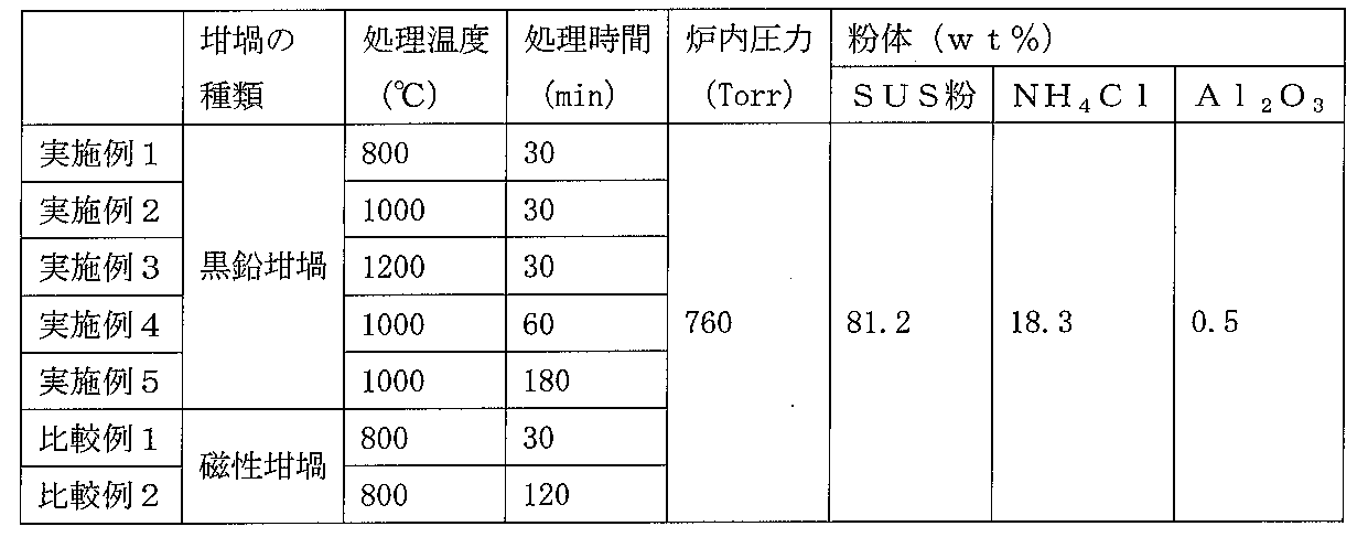
- a mixed powder consisting of a graphite crucible (manufactured by Toyo Tanso Co., Ltd., model number IG-11), stainless steel powder (SUS314 powder), ammonium chloride (NH 4 Cl), and alumina powder (Al 2 O 3 )
- the body is filled, and the mixed powder is filled with a carbon base material having a width of 10 mm, a length of 60 mm, and a thickness of 10 mm (dense isotropic graphite subjected to cold isostatic pressing; 8, an average pore radius of 5 ⁇ m, porosity of 20%) was embedded, covered, placed in a heating furnace, and heat-treated. During heating, nitrogen was introduced from the intake port and naturally exhausted from the exhaust port.
- Example 2 About the manufactured carbon material heat-processed in the said Example and comparative example, the following item was evaluated and an evaluation result is shown in Table 2.
- State (state) of the layer formed on the carbon substrate The produced carbon material was evaluated by visual observation and observation with a cross-sectional SEM.
- Identification of the layer formed on the carbon substrate (metal carbide layer) The manufactured carbon material was identified by performing metal analysis in a vacuum using an EPMA analyzer: EMAX7000 manufactured by Horiba, Ltd.
- Thickness (thickness) of the layer formed on the carbon substrate The produced carbon material was evaluated by visual observation and observation with a cross-sectional SEM.
- Adhesion strength Adhesion strength
- the carbon member When the carbon member is not used as in the above result, it cannot be formed on the entire surface of the carbon base material, color unevenness occurs, and a metal carbide layer cannot be uniformly formed on the carbon base material. It was. Moreover, it turns out that the carbon material manufactured by the manufacturing method of the carbon material of this invention has very high adhesiveness with the metal layer formed later.
- the method for producing a carbon material of the present invention can modify the surface of a carbon substrate only by a very simple process of embedding the carbon substrate in powder and heating.
Abstract
Description
上記炭素部材としては、黒鉛坩堝等の炭素からなる容器、炭素粉末などが挙げられる。また、加熱処理の際の条件としては、常圧で行うことができる。更に、上記遷移金属を含む金属粒子としては、遷移金属粒子又は遷移金属を含む合金粒子を用いることができるが、特に、ステンレス等のCrを含む合金を使用することが好ましい。これは、Crを含む合金を使用することにより、Crを含む炭化金属と、金属を含む炭化金属層を一回の加熱処理で形成することができるからである。 The method for producing a carbon material according to the present invention includes a carbon base material embedded in a surface modifier containing metal particles containing a transition metal and a pyrolytic hydrogen halide generator, together with a carbon member other than the carbon base material. It is characterized by heat treatment.
Examples of the carbon member include containers made of carbon such as a graphite crucible, carbon powder, and the like. Moreover, as conditions in the case of heat processing, it can carry out at a normal pressure. Furthermore, as the metal particles containing the transition metal, transition metal particles or alloy particles containing a transition metal can be used, and it is particularly preferable to use an alloy containing Cr such as stainless steel. This is because a metal carbide containing Cr and a metal carbide layer containing a metal can be formed by a single heat treatment by using an alloy containing Cr.
この炭素材は、本発明の炭素材の製造方法により好ましく製造することができる。製造方法において、遷移金属を含む金属粉としてステンレス粉を使用することにより、炭素基材にCr2CまたはCr3C2を含み、NiおよびFeを含む炭化金属層を1度の処理で容易に形成することができる。 The carbon material of the present invention has a metal carbide layer containing M 2 C or M 3 C 2 (M: transition metal element) on a carbon substrate, and has a metal or alloy layer on the metal carbide layer. It is characterized by. The M is preferably Cr, and the metal contained in the metal carbide layer is preferably a transition metal such as Cr, Fe, Ni. The thickness of the metal carbide layer is preferably 100 μm or less.
This carbon material can be preferably manufactured by the carbon material manufacturing method of the present invention. In the manufacturing method, by using stainless steel powder as a metal powder containing a transition metal, a carbon carbide layer containing Cr 2 C or Cr 3 C 2 on a carbon base material and containing Ni and Fe can be easily treated by a single treatment. Can be formed.
また、減圧を必要とせず、常圧(大気圧中)にて加熱処理することができ、処理を簡易にすることができる。 According to the method for producing a carbon material of the present invention, by using a carbon member, a carbon member such as carbon powder, the processing time can be shortened, and the supply of hydrogen gas can be made unnecessary. It is possible to modify the surface of the carbon substrate more easily. Thereby, while improving adhesiveness with layers, such as a metal formed later on the surface, intensity | strength can be improved rather than a carbon base material.
In addition, heat treatment can be performed at normal pressure (in atmospheric pressure) without the need for reduced pressure, and the treatment can be simplified.
本発明における炭素材の製造方法では、遷移金属を含む金属粒子と熱分解性ハロゲン化水素発生剤等とを含む表面改質剤(粉体状)に埋め込まれた炭素基材を、該炭素基材以外の炭素部材とともに加熱処理する。 Hereinafter, the present invention will be described in detail.
In the method for producing a carbon material in the present invention, a carbon base material embedded in a surface modifier (powder) containing metal particles containing a transition metal and a thermally decomposable hydrogen halide generator is used. It heat-processes with carbon members other than a material.
熱処理の時間は、1時間未満の処理にて炭素基材に炭化金属層を色むらなくほぼ均一に形成することができる。この炭化金属層は、30分もあれば十分形成することができる。この処理時間は、炭化金属層を厚くする必要がある場合には、より長時間、たとえば1時間以上行ってもよい。 In the method for producing a carbon material of the present invention, the carbon substrate to be treated is heat-treated together with a carbon member other than the carbon substrate. Examples of the carbon member include a container made of carbon such as a graphite crucible, carbon powder, and the like. Thus, a metal carbide layer can be formed in a carbon base material in a short time by heat-processing the carbon base material which should be processed with a carbon member. This is because the use of the carbon member can efficiently use materials such as transition metals and pyrolytic hydrogen halide generators contained in the powder for the surface treatment of the carbon substrate, so that the required amount of heat can be reduced. This is presumed to be possible.
With the heat treatment time of less than 1 hour, the metal carbide layer can be formed almost uniformly on the carbon substrate without color unevenness. This metal carbide layer can be sufficiently formed in 30 minutes. When the metal carbide layer needs to be thickened, this treatment time may be longer, for example, 1 hour or longer.
この熱分解性ハロゲン化水素発生剤としては、入手のしやすさから塩化アンモニウムが好ましい。 The thermally decomposable hydrogen halide generator is a substance that maintains a solid state at normal temperature and normal pressure and decomposes by heating to generate hydrogen halides such as hydrogen chloride, hydrogen fluoride, and hydrogen bromide. The thermal decomposition temperature of the thermally decomposable hydrogen halide generator is preferably 200 ° C. or higher because it is easy to handle before heating. The hydrogen halide generated from the thermally decomposable hydrogen halide generator reacts with the transition metal during the heat treatment to generate a metal halide gas. By treating the carbon substrate with the metal halide gas, a metal carbide layer can be formed on the surface of the carbon substrate. Since the carbon substrate is treated with gas in this way, a metal carbide layer is formed almost uniformly on the carbon substrate even when the carbon substrate has a complicated shape such as holes and grooves. can do.
As the thermally decomposable hydrogen halide generator, ammonium chloride is preferable because of its availability.
特にCr、NiおよびFeを含む合金であるステンレスからなる金属粒子を用いた場合には、炭素基材の表面に炭化クロムおよびNi,Feを含む層を1回の加熱処理にて形成することができる。
特に、Cr、NiおよびFeを含む合金であるステンレスと塩化アンモニウムを含む粉末を用いて加熱処理することが、取り扱いの容易さ、ならびにコスト面においても好ましい。 The metal particles containing the transition metal only need to contain a transition metal, and examples thereof include mixed powders and alloy powders of transition metals and other metals. Examples of the transition metal include Ti, V, Cr, Mn, Fe, Co, Ni, Cu, Zn, Zr, Nb, Mo, Ta, and the like, but react with the hydrogen halide to generate a metal halide gas. There is no particular limitation as long as it occurs. Then, the generated metal halide gas reacts with the carbon on the surface of the carbon substrate to generate metal carbide. These transition metals preferably contain Cr because of their high reactivity. The metal particles are preferably alloy powders containing Cr, such as stainless steel.
In particular, when metal particles made of stainless steel, which is an alloy containing Cr, Ni and Fe, are used, a layer containing chromium carbide and Ni, Fe can be formed on the surface of the carbon substrate by a single heat treatment. it can.
In particular, heat treatment using a powder containing stainless steel and ammonium chloride, which is an alloy containing Cr, Ni, and Fe, is preferable in terms of ease of handling and cost.
炭素部材を用いることにより、炭素基材の処理時間を短縮することができるとともに、水素ガスの供給を不要にすることができ、より簡易に炭素基材を表面改質することができる。これにより、後に表面に形成される金属等の層との密着性を向上させるとともに、炭素基材よりも強度を向上させることができる。また、減圧を必要とせず、常圧(大気圧中)にて加熱処理することができ、処理を簡易にすることができる。
上記炭素部材としては、黒鉛坩堝を用いることが好ましい。処理する際に黒鉛坩堝を用いることにより、埋め込まれた炭素基材の周囲における気体の流れを抑制することができ、炭素基材の表面に色むらなくより均一に炭化金属層を形成することができる。また、粉体から発生したガスを黒鉛坩堝内にある程度留めておけるため、発生したガスを有効利用することができる。この黒鉛坩堝には蓋をしておくことが好ましく、この蓋により炭素基材の周囲における気体の流れをより抑制することができる。この蓋としては、黒鉛製のもの、黒鉛からなるシート等が挙げられる。また、容器内で発生する気体を逃がすために、容器または蓋に通気孔を設けておくことが好ましい。なお、黒鉛からなるシートを使用する場合には、単に覆っているだけであるため、特に通気孔は必要ではない。 Examples of the carbon member include a container made of carbon, such as a graphite crucible, and carbon powder.
By using the carbon member, the processing time of the carbon base material can be shortened, the supply of hydrogen gas can be made unnecessary, and the surface of the carbon base material can be more easily modified. Thereby, while improving adhesiveness with layers, such as a metal formed later on the surface, intensity | strength can be improved rather than a carbon base material. In addition, heat treatment can be performed at normal pressure (in atmospheric pressure) without the need for reduced pressure, and the treatment can be simplified.
A graphite crucible is preferably used as the carbon member. By using a graphite crucible when processing, the flow of gas around the embedded carbon substrate can be suppressed, and a metal carbide layer can be more uniformly formed on the surface of the carbon substrate without color unevenness. it can. Further, since the gas generated from the powder can be kept to some extent in the graphite crucible, the generated gas can be used effectively. The graphite crucible is preferably covered with this lid, and the gas flow around the carbon substrate can be further suppressed by this lid. Examples of the lid include those made of graphite, sheets made of graphite, and the like. In order to escape the gas generated in the container, it is preferable to provide a vent hole in the container or the lid. In addition, when using the sheet | seat which consists of graphite, since it is only covering, the ventilation hole is not especially required.
図1に示すように、本発明の炭素材の製造方法に用いられる加熱装置(本加熱装置)は、加熱ヒーターを有する加熱炉1を備え、この加熱炉1内に載置された処理物を加熱処理するようになっている。この加熱炉1には、吸気口4および排気口5が設けられている。この吸気口5からは場合に応じて窒素ガス、アルゴンガス等の不活性ガスが導入できるようになっている。
また、本加熱装置には、加熱炉1内に黒鉛坩堝6が配置されるようになっている。この黒鉛坩堝6には、粉体(表面改質剤)3が充填され、この充填された粉体3に処理される炭素基材2が埋め込まれるようになっており、さらに蓋体7で蓋がされるようになっている。この蓋体7には通気孔が設けられている。この粉体3は、熱分解性ハロゲン化水素発生剤、遷移金属を含む金属粉(金属粒子)が含まれている。なお、この粉体3には反応に関与しないアルミナ粉を添加してもよい。 Next, an example of a heating apparatus for performing the heat treatment in the carbon material manufacturing method of the present invention will be described with reference to FIG. Here, a case where a graphite crucible is used as the carbon member will be described.
As shown in FIG. 1, a heating device (main heating device) used in the method for producing a carbon material of the present invention includes a heating furnace 1 having a heater, and a processing object placed in the heating furnace 1 is processed. It is designed to be heat treated. The heating furnace 1 is provided with an intake port 4 and an exhaust port 5. From the intake port 5, an inert gas such as nitrogen gas or argon gas can be introduced according to circumstances.
In the present heating apparatus, a graphite crucible 6 is arranged in the heating furnace 1. The graphite crucible 6 is filled with powder (surface modifying agent) 3, and the
この構成により、本発明の炭素材と、金属部材とを接合する際に金属材からなる接合材を用いた接合が容易であり、接合強度を向上させることができる。このように、炭化金属層上に金属層を積層することにより、炭素材を金属部材に接合することが可能となる。これにより、金属単体では達成しえなかった炭素材の特性を、金属材に付与することが可能となる。 The carbon material of the present invention has a metal carbide layer containing M 2 C or M 3 C 2 (M: transition metal element) and a metal on a carbon substrate, and the metal layer is formed on the metal carbide layer. Have. The M is preferably Cr, and the metal contained in the metal carbide layer is preferably a transition metal such as Cr, Fe, Ni, or an alloy thereof. The maximum thickness of the metal carbide layer is preferably 100 μm or less. On the other hand, if the minimum thickness of the metal carbide layer exceeds 0 μm, the effects of the present invention can be exhibited, but it is preferably 0.5 μm or more in order to fully exhibit the effects.
With this configuration, when the carbon material of the present invention and the metal member are joined, joining using the joining material made of the metal material is easy, and the joining strength can be improved. Thus, it becomes possible to join a carbon material to a metal member by laminating a metal layer on a metal carbide layer. Thereby, it becomes possible to impart to the metal material the characteristics of the carbon material that could not be achieved with a single metal.
また、メッキ層などを強固に形成することができるため、アルミニウム板等の金属板に容易に接着剤にて接着することができ、放熱板として使用することもできる。 The carbon material concerning this invention can be manufactured by processing in the manufacturing method of the carbon material of the said invention using the transition metal from which reactivity differs. It is preferable that Cr is contained as a transition metal because the high reactivity of Cr with carbon can be used, and thus a carbon material having a metal carbide layer containing Cr 2 C can be easily manufactured. Furthermore, a carbon material having a metal carbide layer containing Cr 2 C, Fe, and Ni can be easily manufactured by a single process by using a powder such as stainless steel containing Cr, Fe, and Ni. This is very preferable because a plated layer of Ni or the like can be easily formed.
Moreover, since a plating layer etc. can be formed firmly, it can adhere | attach easily on metal plates, such as an aluminum plate, with an adhesive agent, and can also be used as a heat sink.
実施例1と同様にして、黒鉛坩堝を用いず、黒鉛坩堝の代わりに磁性坩堝を容器として使用し、炭素基材を加熱処理した。
なお、実施例および比較例における処理条件については表1に示す通りである。
In the same manner as in Example 1, the carbon base material was heat-treated without using the graphite crucible, using a magnetic crucible as a container instead of the graphite crucible.
The processing conditions in the examples and comparative examples are as shown in Table 1.
(1)炭素基材に形成された層の状態(状態)
製造された炭素材について目視および、断面SEMで観察して評価した。
(2)炭素基材に形成された層の同定(炭化金属層)
製造された炭素材について、株式会社堀場製作所製、EPMA分析器:EMAX7000を用い、真空中にて金属の分析を行うことにより同定した。
(3)炭素基材に形成された層の厚さ(厚さ)
製造された炭素材について目視および、断面SEMで観察して評価した。
(4)製造された炭素材と該炭素材に形成した金属層との密着強度(密着強度)
製造された炭素材について、無電解メッキ法によりNiメッキ層を2μm形成し、メッキ層の密着強度をJIS H 8666に準拠して測定した。 About the manufactured carbon material heat-processed in the said Example and comparative example, the following item was evaluated and an evaluation result is shown in Table 2.
(1) State (state) of the layer formed on the carbon substrate
The produced carbon material was evaluated by visual observation and observation with a cross-sectional SEM.
(2) Identification of the layer formed on the carbon substrate (metal carbide layer)
The manufactured carbon material was identified by performing metal analysis in a vacuum using an EPMA analyzer: EMAX7000 manufactured by Horiba, Ltd.
(3) Thickness (thickness) of the layer formed on the carbon substrate
The produced carbon material was evaluated by visual observation and observation with a cross-sectional SEM.
(4) Adhesion strength (adhesion strength) between the produced carbon material and the metal layer formed on the carbon material
About the manufactured carbon material, 2 micrometers of Ni plating layers were formed with the electroless-plating method, and the adhesive strength of the plating layer was measured based on JISH8666.

2 炭素基材
3 粉末
4 吸気口
5 排気口
6 黒鉛坩堝
7 蓋体 DESCRIPTION OF SYMBOLS 1
Claims (9)
- 遷移金属を含む金属粒子と熱分解性ハロゲン化水素発生剤とを含む表面改質剤に埋め込まれた炭素基材を、該炭素基材以外の炭素部材とともに加熱処理することを特徴とする炭素材の製造方法。 A carbon material characterized by heat-treating a carbon base material embedded in a surface modifier containing metal particles containing a transition metal and a thermally decomposable hydrogen halide generator together with a carbon member other than the carbon base material Manufacturing method.
- 前記炭素部材は炭素からなる容器であり、上記容器内に上記表面改質剤に埋め込まれた炭素基材を配置した後、これらを加熱処理することを特徴とする請求項1に記載の炭素材の製造方法。 2. The carbon material according to claim 1, wherein the carbon member is a container made of carbon, and the carbon base material embedded in the surface modifier is disposed in the container, and thereafter, the carbon member is heat-treated. Manufacturing method.
- 前記炭素部材は炭素粉末であり、該炭素粉末と、遷移金属を含む金属粒子と、熱分解性ハロゲン化水素発生剤とを含む表面改質剤に埋め込まれた炭素基材を、加熱処理することを特徴とする請求項1または2に記載の炭素材の製造方法。 The carbon member is carbon powder, and a carbon base material embedded in a surface modifier containing the carbon powder, metal particles containing a transition metal, and a thermally decomposable hydrogen halide generator is heated. The method for producing a carbon material according to claim 1 or 2.
- 前記加熱処理を、常圧にて行うことを特徴とする請求項1~3のいずれか1項に記載の炭素材の製造方法。 The method for producing a carbon material according to any one of claims 1 to 3, wherein the heat treatment is performed at normal pressure.
- 前記金属粒子は、Crを含む合金の粒子であり、炭素基材の表面にCr2CまたはCr3C2および金属を含む炭化金属層を形成することを特徴とする請求項1~4のいずれか1項に記載の炭素材の製造方法。 5. The metal particles according to claim 1, wherein the metal particles are particles of an alloy containing Cr, and a metal carbide layer containing Cr 2 C or Cr 3 C 2 and a metal is formed on the surface of the carbon substrate. A method for producing the carbon material according to claim 1.
- 前記熱分解性ハロゲン化水素発生剤は、塩化アンモニウムであることを特徴とする請求項1~5のいずれか1項に記載の炭素材の製造方法。 The method for producing a carbon material according to any one of claims 1 to 5, wherein the thermally decomposable hydrogen halide generator is ammonium chloride.
- 炭素基材上にM2CまたはM3C2(M:遷移金属元素)および金属を含む炭化金属層を有し、該炭化金属層上に金属層を有することを特徴とする炭素材。 A carbon material having a metal carbide layer containing M 2 C or M 3 C 2 (M: transition metal element) and a metal on a carbon substrate, and having the metal layer on the metal carbide layer.
- 前記炭化金属層の厚さは、100μm以下であることを特徴とする請求項7に記載の炭素材。 The carbon material according to claim 7, wherein the thickness of the metal carbide layer is 100 μm or less.
- 前記炭化金属層は、Cr2CまたはCr3C2を含み、さらにNiおよびFeを含むことを特徴とする請求項7または8に記載の炭素材。 The carbon material according to claim 7 or 8, wherein the metal carbide layer contains Cr 2 C or Cr 3 C 2 and further contains Ni and Fe.
Priority Applications (3)
| Application Number | Priority Date | Filing Date | Title |
|---|---|---|---|
| US13/133,344 US9067834B2 (en) | 2008-12-08 | 2009-12-02 | Method of manufacturing a carbon material and the carbon material |
| EP09831838.9A EP2374776A4 (en) | 2008-12-08 | 2009-12-02 | Method for producing carbon material, and carbon material |
| CN200980145499.2A CN102216241B (en) | 2008-12-08 | 2009-12-02 | Method for producing carbon material, and carbon material |
Applications Claiming Priority (2)
| Application Number | Priority Date | Filing Date | Title |
|---|---|---|---|
| JP2008-312662 | 2008-12-08 | ||
| JP2008312662A JP5415061B2 (en) | 2008-12-08 | 2008-12-08 | Carbon material manufacturing method and carbon material |
Publications (1)
| Publication Number | Publication Date |
|---|---|
| WO2010067734A1 true WO2010067734A1 (en) | 2010-06-17 |
Family
ID=42242722
Family Applications (1)
| Application Number | Title | Priority Date | Filing Date |
|---|---|---|---|
| PCT/JP2009/070226 WO2010067734A1 (en) | 2008-12-08 | 2009-12-02 | Method for producing carbon material, and carbon material |
Country Status (7)
| Country | Link |
|---|---|
| US (1) | US9067834B2 (en) |
| EP (1) | EP2374776A4 (en) |
| JP (1) | JP5415061B2 (en) |
| KR (1) | KR20110092275A (en) |
| CN (1) | CN102216241B (en) |
| TW (1) | TWI500779B (en) |
| WO (1) | WO2010067734A1 (en) |
Cited By (2)
| Publication number | Priority date | Publication date | Assignee | Title |
|---|---|---|---|---|
| WO2012090535A1 (en) * | 2010-12-27 | 2012-07-05 | 東洋炭素株式会社 | Carbon material, jig, and method for producing carbon material |
| WO2012115072A1 (en) * | 2011-02-21 | 2012-08-30 | 東洋炭素株式会社 | Carbon material, and method for production thereof |
Families Citing this family (4)
| Publication number | Priority date | Publication date | Assignee | Title |
|---|---|---|---|---|
| EP2516048B1 (en) | 2009-12-24 | 2019-10-02 | LG Innotek Co., Ltd. | Heat treatment container for vacuum heat treatment apparatus |
| JP6273166B2 (en) * | 2014-05-19 | 2018-01-31 | 株式会社神戸製鋼所 | Carbon material manufacturing method |
| US10407769B2 (en) * | 2016-03-18 | 2019-09-10 | Goodrich Corporation | Method and apparatus for decreasing the radial temperature gradient in CVI/CVD furnaces |
| CN113529040A (en) * | 2020-07-06 | 2021-10-22 | 深圳市海维通光电技术有限公司 | Carbon material surface treatment method |
Citations (3)
| Publication number | Priority date | Publication date | Assignee | Title |
|---|---|---|---|---|
| JPS60192698A (en) * | 1983-12-20 | 1985-10-01 | 三菱鉛筆株式会社 | Method of coating carbide with metal |
| JPH08143385A (en) | 1994-11-17 | 1996-06-04 | Tocalo Co Ltd | Carbon member with combined coating film and its production |
| JPH08143384A (en) | 1994-11-17 | 1996-06-04 | Tocalo Co Ltd | Carbon member and its production |
Family Cites Families (12)
| Publication number | Priority date | Publication date | Assignee | Title |
|---|---|---|---|---|
| US3151852A (en) * | 1958-07-09 | 1964-10-06 | Chrysler Corp | Process for obtaining metal carbide coatings on base materials and metal carbide structures produced thereby |
| US3912827A (en) * | 1973-11-13 | 1975-10-14 | Toyota Chuo Kenkyusko Kk | Method for forming a chromium carbide layer on the surface of an iron, ferrous alloy or cemented carbide article |
| US4256496A (en) * | 1977-12-16 | 1981-03-17 | Ontario Research Foundation | Production of metal carbides in pure form |
| AU570799B2 (en) * | 1984-05-17 | 1988-03-24 | Toyota Chuo Kenkyusho K.K. | Vapour phase coating of carbide in fluidised bed |
| US5322824A (en) * | 1993-05-27 | 1994-06-21 | Chia Kai Y | Electrically conductive high strength dense ceramic |
| JPH0859373A (en) * | 1994-08-25 | 1996-03-05 | Akechi Ceramics Kk | Oxidation preventive coating of carbon material |
| US5855955A (en) * | 1995-06-07 | 1999-01-05 | Lanxide Technology Company L.P. | Method for making self-supporting composite bodies |
| US5942204A (en) * | 1997-03-31 | 1999-08-24 | Omg Americas, Inc. | Method to produce a transition metal carbide from a partially reduced transition metal compound |
| JP2004155598A (en) * | 2002-11-01 | 2004-06-03 | Honda Motor Co Ltd | High temperature oxidation resistant carbonaceous shaped article and method of producing the same |
| US7163963B2 (en) * | 2003-09-08 | 2007-01-16 | Conocophillips Company | Chemically and thermally stabilized alumina for Fischer-Tropsch catalysts |
| CN1745036A (en) * | 2003-12-05 | 2006-03-08 | 三菱重工业株式会社 | Carbon material and flue gas treatment apparatus |
| JP2008137819A (en) * | 2006-11-30 | 2008-06-19 | Honda Motor Co Ltd | Method for production of c/c composite material, and c/c composite material |
-
2008
- 2008-12-08 JP JP2008312662A patent/JP5415061B2/en not_active Expired - Fee Related
-
2009
- 2009-12-02 CN CN200980145499.2A patent/CN102216241B/en not_active Expired - Fee Related
- 2009-12-02 EP EP09831838.9A patent/EP2374776A4/en not_active Withdrawn
- 2009-12-02 KR KR1020117010954A patent/KR20110092275A/en not_active Application Discontinuation
- 2009-12-02 US US13/133,344 patent/US9067834B2/en not_active Expired - Fee Related
- 2009-12-02 WO PCT/JP2009/070226 patent/WO2010067734A1/en active Application Filing
- 2009-12-07 TW TW098141726A patent/TWI500779B/en not_active IP Right Cessation
Patent Citations (3)
| Publication number | Priority date | Publication date | Assignee | Title |
|---|---|---|---|---|
| JPS60192698A (en) * | 1983-12-20 | 1985-10-01 | 三菱鉛筆株式会社 | Method of coating carbide with metal |
| JPH08143385A (en) | 1994-11-17 | 1996-06-04 | Tocalo Co Ltd | Carbon member with combined coating film and its production |
| JPH08143384A (en) | 1994-11-17 | 1996-06-04 | Tocalo Co Ltd | Carbon member and its production |
Non-Patent Citations (1)
| Title |
|---|
| See also references of EP2374776A4 * |
Cited By (7)
| Publication number | Priority date | Publication date | Assignee | Title |
|---|---|---|---|---|
| WO2012090535A1 (en) * | 2010-12-27 | 2012-07-05 | 東洋炭素株式会社 | Carbon material, jig, and method for producing carbon material |
| JP2012136383A (en) * | 2010-12-27 | 2012-07-19 | Toyo Tanso Kk | Carbon material, jig, and method for producing carbon material |
| CN103180270A (en) * | 2010-12-27 | 2013-06-26 | 东洋炭素株式会社 | Carbon material, jig, and method for producing carbon material |
| WO2012115072A1 (en) * | 2011-02-21 | 2012-08-30 | 東洋炭素株式会社 | Carbon material, and method for production thereof |
| JP2012171823A (en) * | 2011-02-21 | 2012-09-10 | Toyo Tanso Kk | Carbon material and method for production thereof |
| CN103328411A (en) * | 2011-02-21 | 2013-09-25 | 东洋炭素株式会社 | Carbon material, and method for production thereof |
| US8896099B2 (en) | 2011-02-21 | 2014-11-25 | Toyo Tanso Co., Ltd. | Carbon material and method of manufacturing the same |
Also Published As
| Publication number | Publication date |
|---|---|
| EP2374776A1 (en) | 2011-10-12 |
| CN102216241B (en) | 2014-09-10 |
| EP2374776A4 (en) | 2016-04-06 |
| US9067834B2 (en) | 2015-06-30 |
| TW201030156A (en) | 2010-08-16 |
| JP2010132518A (en) | 2010-06-17 |
| TWI500779B (en) | 2015-09-21 |
| US20110244267A1 (en) | 2011-10-06 |
| JP5415061B2 (en) | 2014-02-12 |
| KR20110092275A (en) | 2011-08-17 |
| CN102216241A (en) | 2011-10-12 |
Similar Documents
| Publication | Publication Date | Title |
|---|---|---|
| JP5415061B2 (en) | Carbon material manufacturing method and carbon material | |
| JP5082845B2 (en) | High thermal conductivity graphite particle dispersed composite and method for producing the same | |
| EP2208706B1 (en) | Metal-coated carbon material and carbon-metal composite material using the same | |
| WO2015122378A1 (en) | Boron nitride particles and production method therefor | |
| JPS59227765A (en) | Manufacture of ceramic super fine particle | |
| CN106756775B (en) | A kind of alloy surface forms the preparation method of spinelle coating | |
| JP5552303B2 (en) | Carbon material manufacturing method | |
| JPH1046268A (en) | Manufacture of porous ni-cr alloy | |
| TW201418190A (en) | Carbon material having thermal sprayed coating layer | |
| JP2007126755A (en) | Carbon-coated metal particle and method for manufacturing the same | |
| JPH08143384A (en) | Carbon member and its production | |
| JP5670175B2 (en) | Jig | |
| WO2012032858A1 (en) | Carbon material and process for producing same | |
| JP3081764B2 (en) | Carbon member having composite coating and method of manufacturing the same | |
| EP2679565A1 (en) | Carbon material, and method for production thereof | |
| Morizono et al. | Effect of Heating Conditions on Surface Modification of Titanium with a Mixture of Iron, Graphite and Alumina Powders | |
| TW201134757A (en) | Carbon material and method for producing the same | |
| JP2024031057A (en) | Manufacturing method of modified metal material | |
| JPS60149761A (en) | Coating method for providing corrosion resistance | |
| JPH0641615A (en) | Production of aluminum sintered porous material |
Legal Events
| Date | Code | Title | Description |
|---|---|---|---|
| WWE | Wipo information: entry into national phase |
Ref document number: 200980145499.2 Country of ref document: CN |
|
| 121 | Ep: the epo has been informed by wipo that ep was designated in this application |
Ref document number: 09831838 Country of ref document: EP Kind code of ref document: A1 |
|
| ENP | Entry into the national phase |
Ref document number: 20117010954 Country of ref document: KR Kind code of ref document: A |
|
| WWE | Wipo information: entry into national phase |
Ref document number: 13133344 Country of ref document: US |
|
| NENP | Non-entry into the national phase |
Ref country code: DE |
|
| WWE | Wipo information: entry into national phase |
Ref document number: 2009831838 Country of ref document: EP |