WO2010064572A1 - 磁気共鳴イメージング装置および同期撮像方法 - Google Patents
磁気共鳴イメージング装置および同期撮像方法 Download PDFInfo
- Publication number
- WO2010064572A1 WO2010064572A1 PCT/JP2009/069945 JP2009069945W WO2010064572A1 WO 2010064572 A1 WO2010064572 A1 WO 2010064572A1 JP 2009069945 W JP2009069945 W JP 2009069945W WO 2010064572 A1 WO2010064572 A1 WO 2010064572A1
- Authority
- WO
- WIPO (PCT)
- Prior art keywords
- echo signal
- measurement
- magnetic resonance
- period
- resonance imaging
- Prior art date
- Legal status (The legal status is an assumption and is not a legal conclusion. Google has not performed a legal analysis and makes no representation as to the accuracy of the status listed.)
- Ceased
Links
Images




Classifications
-
- A—HUMAN NECESSITIES
- A61—MEDICAL OR VETERINARY SCIENCE; HYGIENE
- A61B—DIAGNOSIS; SURGERY; IDENTIFICATION
- A61B5/00—Measuring for diagnostic purposes; Identification of persons
- A61B5/05—Detecting, measuring or recording for diagnosis by means of electric currents or magnetic fields; Measuring using microwaves or radio waves
- A61B5/055—Detecting, measuring or recording for diagnosis by means of electric currents or magnetic fields; Measuring using microwaves or radio waves involving electronic [EMR] or nuclear [NMR] magnetic resonance, e.g. magnetic resonance imaging
-
- A—HUMAN NECESSITIES
- A61—MEDICAL OR VETERINARY SCIENCE; HYGIENE
- A61B—DIAGNOSIS; SURGERY; IDENTIFICATION
- A61B5/00—Measuring for diagnostic purposes; Identification of persons
- A61B5/72—Signal processing specially adapted for physiological signals or for diagnostic purposes
- A61B5/7271—Specific aspects of physiological measurement analysis
- A61B5/7285—Specific aspects of physiological measurement analysis for synchronizing or triggering a physiological measurement or image acquisition with a physiological event or waveform, e.g. an ECG signal
-
- G—PHYSICS
- G01—MEASURING; TESTING
- G01R—MEASURING ELECTRIC VARIABLES; MEASURING MAGNETIC VARIABLES
- G01R33/00—Arrangements or instruments for measuring magnetic variables
- G01R33/20—Arrangements or instruments for measuring magnetic variables involving magnetic resonance
- G01R33/44—Arrangements or instruments for measuring magnetic variables involving magnetic resonance using nuclear magnetic resonance [NMR]
- G01R33/48—NMR imaging systems
- G01R33/54—Signal processing systems, e.g. using pulse sequences ; Generation or control of pulse sequences; Operator console
- G01R33/56—Image enhancement or correction, e.g. subtraction or averaging techniques, e.g. improvement of signal-to-noise ratio and resolution
- G01R33/567—Image enhancement or correction, e.g. subtraction or averaging techniques, e.g. improvement of signal-to-noise ratio and resolution gated by physiological signals, i.e. synchronization of acquired MR data with periodical motion of an object of interest, e.g. monitoring or triggering system for cardiac or respiratory gating
- G01R33/5673—Gating or triggering based on a physiological signal other than an MR signal, e.g. ECG gating or motion monitoring using optical systems for monitoring the motion of a fiducial marker
-
- G—PHYSICS
- G01—MEASURING; TESTING
- G01R—MEASURING ELECTRIC VARIABLES; MEASURING MAGNETIC VARIABLES
- G01R33/00—Arrangements or instruments for measuring magnetic variables
- G01R33/20—Arrangements or instruments for measuring magnetic variables involving magnetic resonance
- G01R33/44—Arrangements or instruments for measuring magnetic variables involving magnetic resonance using nuclear magnetic resonance [NMR]
- G01R33/48—NMR imaging systems
- G01R33/54—Signal processing systems, e.g. using pulse sequences ; Generation or control of pulse sequences; Operator console
- G01R33/56—Image enhancement or correction, e.g. subtraction or averaging techniques, e.g. improvement of signal-to-noise ratio and resolution
- G01R33/561—Image enhancement or correction, e.g. subtraction or averaging techniques, e.g. improvement of signal-to-noise ratio and resolution by reduction of the scanning time, i.e. fast acquiring systems, e.g. using echo-planar pulse sequences
-
- G—PHYSICS
- G01—MEASURING; TESTING
- G01R—MEASURING ELECTRIC VARIABLES; MEASURING MAGNETIC VARIABLES
- G01R33/00—Arrangements or instruments for measuring magnetic variables
- G01R33/20—Arrangements or instruments for measuring magnetic variables involving magnetic resonance
- G01R33/44—Arrangements or instruments for measuring magnetic variables involving magnetic resonance using nuclear magnetic resonance [NMR]
- G01R33/48—NMR imaging systems
- G01R33/54—Signal processing systems, e.g. using pulse sequences ; Generation or control of pulse sequences; Operator console
- G01R33/56—Image enhancement or correction, e.g. subtraction or averaging techniques, e.g. improvement of signal-to-noise ratio and resolution
- G01R33/565—Correction of image distortions, e.g. due to magnetic field inhomogeneities
- G01R33/56509—Correction of image distortions, e.g. due to magnetic field inhomogeneities due to motion, displacement or flow, e.g. gradient moment nulling
Definitions
- the present invention relates to a magnetic resonance imaging apparatus for measuring nuclear magnetic resonance (hereinafter referred to as “NMR”) signals from hydrogen, phosphorus, etc. in a subject and imaging nuclear density distribution, relaxation time distribution, etc.
- NMR nuclear magnetic resonance
- the present invention relates to a measurement method, and particularly relates to improvement in imaging efficiency of synchronous measurement.
- ⁇ MRI '' Nuclear magnetic resonance imaging
- NMR signals echo signals
- the echo signal is given different phase encoding depending on the gradient magnetic field and is frequency-encoded and measured as time-series data.
- the measured echo signal is reconstructed into an image by two-dimensional or three-dimensional Fourier transform.
- imaging with the MRI apparatus generally requires imaging time of several minutes to several tens of minutes, body movement such as heartbeat and breathing of the subject cannot be avoided during imaging. For this reason, it is known that artifacts derived from body movement occur on the image and the image quality deteriorates.
- a biological signal is detected by attaching a cardiac electrode or a pulse wave sensor to the subject as disclosed in Patent Documents 1 to 3, and detection is performed.
- a method is used in which the captured biological signal is used as a trigger signal and the timing at which echo signals are collected is synchronized with the motion of the heart and the like.
- artifacts on images derived from body movements are excellent by selectively measuring echo signals only in the time phase of a relatively small movement of the subject in synchronization with the trigger signal. Is suppressed.
- Patent Document 1 and Patent Document 2 there remains a problem that the imaging time is extended in order to selectively measure the echo signal only in the time phase of a relatively small movement of the subject.
- a three-dimensional scan is performed in which the operation of collecting echo signals for a predetermined slice encoding amount is repeated for every certain number of heartbeats in the diastole. This eliminates the influence of turbulent blood flow and measures the echo signal in a stable blood flow state to increase the contrast of the reconstructed image, but repeats the pulse sequence every certain number of heartbeats For this reason, the problem of extending the imaging time remains unsolved.
- an object of the present invention is to maintain a desired image contrast and shorten an imaging time in imaging using an MRI apparatus in synchronization with a subject's periodic body movement information.
- the present invention provides an echo signal measurement period in a synchronous measurement of an echo signal synchronized with trigger information detected from the periodic body motion information of a subject having periodic body motion. , Providing at least one of the first period before and the second period after, dividing the K space into a plurality of partial areas, measuring echo signals corresponding to the partial areas on the low spatial frequency side, and the high spatial frequency side At least one of the first period and the second period is made different in the measurement of the echo signal corresponding to the partial area.
- the MRI apparatus of the present invention controls a detection unit that detects trigger information from periodic body movement information of a subject, and synchronous measurement that measures an echo signal from the subject in synchronization with the trigger information.
- a measurement control unit, and an arithmetic processing unit that acquires an image of a subject based on K space data in which echo signal data is arranged in K space, and synchronous measurement is performed during an echo signal measurement period, At least one of the first period and the second period is provided before, the arithmetic processing unit divides the K space into a plurality of partial regions, and the measurement control unit echoes corresponding to the partial region on the low spatial frequency side. At least one of the first period and the second period is made different between the signal measurement and the echo signal measurement corresponding to the partial region on the high spatial frequency side.
- the synchronous imaging method of the present invention also includes a detection process for detecting trigger information from periodic body motion information of a subject, and a measurement system for controlling synchronous measurement for measuring an echo signal from the subject in synchronization with the trigger information.
- At least one of the first period before and the second period after the signal measurement period is provided, and the measurement control step includes measuring the echo signal corresponding to the partial area on the low spatial frequency side, and measuring the high spatial frequency side. At least one of the first period and the second period is made different in the measurement of the echo signal corresponding to the partial region.
- the imaging time can be shortened while maintaining a desired image contrast in imaging synchronized with the periodic body motion information of the subject.
- FIG. 1 is a block diagram showing an overall basic configuration of an embodiment of an MRI apparatus according to the present invention.
- FIG. 3 is a diagram showing an example of electrocardiographic synchronization measurement according to the first embodiment of the present invention.
- (a) is a figure which shows the R wave of the electrocardiogram waveform as a trigger signal, and the time table of echo signal measurement, respectively.
- (b) is a diagram showing a sequence chart of a pulse sequence for echo signal measurement.
- FIG. 5 is a follow chart showing process follow of the first embodiment of the present invention.
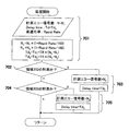
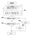
- the flowchart which shows the determination processing flow of the echo data number (N) measured in 1 heartbeat cycle.
- FIG. 10 is a diagram showing an example of electrocardiographic synchronization measurement according to the second embodiment of the present invention.
- (a) is a diagram showing a time table for trigger signal measurement and echo signal measurement when acquiring a T2-weighted image
- (b) is a diagram showing a sequence chart of a pulse sequence for echo signal measurement.
- 9 is a follow chart showing process follow-up according to the second embodiment of the present invention.
- the follow chart which shows the setting processing flow of the trigger signal waiting frequency (NT) according to a partial area.
- FIG. 1 is a block diagram showing the overall configuration of an embodiment of an MRI apparatus according to the present invention.
- This MRI apparatus uses a NMR phenomenon to obtain a tomographic image of a subject.As shown in FIG. 1, the MRI apparatus includes a static magnetic field generation unit 2, a gradient magnetic field generation unit 3, a transmission unit 5, The receiving unit 6, the information processing unit 7, and the measurement control unit 4 are configured.
- the static magnetic field generator 2 generates a uniform static magnetic field in the direction perpendicular to the body axis in the space around the subject 1 if the vertical magnetic field method is used, and in the direction of the body axis if the horizontal magnetic field method is used. Therefore, a permanent magnet type, normal conducting type or superconducting type static magnetic field generating source is arranged around the subject 1.
- the gradient magnetic field generator 3 includes a gradient magnetic field coil 9 wound in the three-axis directions of X, Y, and Z, which are coordinate systems (stationary coordinate system) of the MRI apparatus, and a gradient magnetic field power source 10 that drives each gradient magnetic field coil It consists of.
- the gradient magnetic field power supply 10 of each coil is driven in accordance with a command from the measurement control unit 4 to be described later, so that the subject 1 lies in the gradient magnetic fields Gx, Gy, and Gz in the X, Y, and Z directions. Applied to the static magnetic field space.
- a slice direction gradient magnetic field pulse is applied in a direction orthogonal to the slice plane (imaging cross section) to set a slice plane for the subject 1, and the remaining planes orthogonal to the slice plane and orthogonal to each other are set.
- a phase encoding direction gradient magnetic field pulse (Gp) and a frequency encoding direction gradient magnetic field pulse (Gf) are applied in two directions, and position information in each direction is encoded in the echo signal.
- the transmitter 5 irradiates the subject 1 with a high-frequency magnetic field pulse (hereinafter referred to as “RF pulse”) in order to induce an NMR phenomenon in the nuclear spin of atoms constituting the living tissue of the subject 1.
- RF pulse high-frequency magnetic field pulse
- the high-frequency pulse output from the high-frequency oscillator 11 is amplitude-modulated by the modulator 12 at a timing according to a command from the measurement control unit 4, and after the amplitude-modulated high-frequency pulse is amplified by the high-frequency amplifier 13, the subject 1 By being supplied to the high-frequency coil 14a arranged close to the RF pulse, the subject 1 is irradiated with the RF pulse.
- the receiving unit 6 detects an echo signal emitted by the NMR phenomenon of the nuclear spin constituting the living tissue of the subject 1, and receives a high frequency coil (receiving coil) 14b on the receiving side, a signal amplifier 15, and quadrature detection. And an A / D converter 17.
- the echo signal of the response of the subject 1 induced by the RF pulse irradiated from the high frequency coil 14a on the transmission side is detected by the high frequency coil 14b arranged close to the subject 1 and amplified by the signal amplifier 15. After that, it is divided into two orthogonal signals by the quadrature phase detector 16 at the timing according to the command from the measurement control unit 4, and each is converted into a digital quantity by the A / D converter 17 and calculated as an echo signal. It is sent to the processing unit 7.
- an echo signal converted into a digital quantity is referred to as echo data.
- the measurement control unit 4 controls the gradient magnetic field generation unit 3, the transmission unit 5, and the reception unit 6 on the basis of a predetermined pulse sequence to apply the RF pulse and the gradient magnetic field pulse and to measure the echo signal. It is a control means to repeat.
- the measurement control unit 4 operates under the control of the CPU 8, and sends various commands necessary for echo signal collection necessary for reconstruction of the tomographic image of the subject 1 to the gradient magnetic field generation unit 3, the transmission unit 5, and the reception unit 6. To control them.
- the information processing unit 7 performs various data processing and display and storage of processing results, and includes a CPU (arithmetic processing unit) 8, an external storage device such as an optical disk 19 and a magnetic disk 18, and a display 20. .
- a CPU arithmetic processing unit
- the echo data is stored in a memory corresponding to the K space in the CPU 8 (hereinafter described that the echo signal or echo data is arranged in the K space. Means that echo data is written and stored in this memory, and echo data arranged in K space is called K space data).
- the CPU 8 performs arithmetic processing such as signal processing and image reconstruction on the K space data, and displays the tomographic image of the subject 1 as a result on the display 20 and records it in the external storage device. To do.
- the operation unit 25 receives input of various control information of the MRI apparatus and control information of processing performed by the arithmetic processing unit 7 from the operator, and includes a trackball or mouse 23 and a keyboard 24.
- the operation unit 25 is disposed close to the display 20, and the operator controls various processes of the MRI apparatus interactively through the operation unit 25 while looking at the display 20.
- the MRI apparatus further includes a cardiac electrode 31 that is attached to the subject and obtains an electrocardiographic waveform signal from the subject, and a signal from the cardiac electrode is input to obtain an electrocardiographic waveform of the subject.
- the electrocardiogram waveform information (an example of periodic body movement information) detected by the electrocardiogram waveform monitor 32 is input to the CPU 8 via the measurement control unit 4, and the measurement control unit 4 synchronizes with the trigger signal (trigger information).
- the synchronous measurement is controlled by controlling each of the above parts based on a predetermined pulse sequence.
- the high-frequency coil 14a and the gradient magnetic field coil 9 on the transmission side are located within the static magnetic field space of the static magnetic field generating unit 2 into which the subject 1 is inserted, and to the subject 1 if the vertical magnetic field method is used. Oppositely, if it is a horizontal magnetic field system, it is installed so as to surround the subject 1. The high-frequency coil 14b on the receiving side is installed so as to face or surround the subject 1.
- the nuclide to be imaged by the current MRI apparatus is a hydrogen nucleus (proton) which is a main constituent material of the subject as widely used in clinical practice.
- K-space division First, the division of the K space according to the present invention will be described.
- the first period before and the second period after the measurement period of the echo signal At least one of the above is provided.
- the K space is divided into a plurality of partial areas, and an echo signal measurement corresponding to the low spatial frequency side partial area and an echo signal measurement corresponding to the high spatial frequency side partial area are performed in the first period. And at least one of the second periods is different.
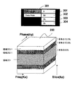
- FIG. 2 shows a three-dimensional K-space 200 in the slice encoding direction (kz), symmetrically with respect to a plane perpendicular to the Slice (kz) axis passing through the origin, and three regions (regions 201, 202, 203) shows an example of division.
- the CPU 8 divides the three-dimensional K space into a partial region 201 on the low spatial frequency side including the origin, and two partial regions 202-1 and 203-1 and 202 on the high spatial frequency side on both sides thereof. -2 and 203-2 (numbers after the hyphen "-" are divided into 1 on the positive side of the K-space slice encoding direction (Kz) and 2 on the negative side). Further, the division ratio can be changed according to the operator's setting.
- the partial area 201 is set to 50% of the entire 3D K space
- the partial area 202 and the partial area 203 are set to be 25% of the entire 3D K space
- the 3D K space is A divided example is shown.
- the K space may be further divided in the phase encoding direction.
- the ratio of each divided area to the entire 3D K space is an imaging parameter that can be changed by the operator.
- the setting of the ratio of each divided region to the entire K space can be performed by an operator via a GUI 300 as shown in FIG. 3, for example.
- the CPU 8 determines the ratio (Data Rate) of each partial area to the whole.
- the tag is displayed on the display 20, and the operator inputs and sets a desired numerical value to the ratio tag (302, 303, 304) for the entire three-dimensional K space for each partial region. Based on these operator setting inputs, the CPU 8 determines the ratio of each partial area and notifies the measurement control unit 4 of this setting information.
- the operator inputs and sets only the segment number # 301 of the three-dimensional K space and the ratio of the partial area on the low spatial frequency side of the K space to the entire K space Data ⁇ Rate 302.
- the CPU 8 calculates and determines the ratio of the remaining partial areas with respect to the entire K space, assuming that the ratio of the remaining partial areas with respect to the entire K space is determined, and measures the ratio of each partial area with the measurement control unit 4. It is also possible to notify.
- heart beat is assumed as body motion
- an electrocardiogram waveform is assumed as periodic body motion information
- an R wave of the electrocardiogram waveform is used as a trigger signal (an example of trigger information)
- an echo signal is synchronized with this trigger signal.
- Each embodiment of the present invention will be described with an example of an electrocardiogram synchronous measurement for controlling the measurement.
- the present invention is not limited to electrocardiographic synchronization measurement, but can be applied to other periodic body movements such as blood flow pulsations and joint periodic movements.
- a delay time is set between the trigger information and the measurement period of the echo signal, and the delay time in the measurement of the echo signal corresponding to the partial area on the high spatial frequency side is set to the low space.
- the delay time in the measurement of the echo signal corresponding to the partial region on the frequency side is made shorter.
- FIG. 5 shows an example of the electrocardiographic synchronization measurement according to the present embodiment, in which the electrocardiographic waveform of the subject is detected and the R wave is used as a trigger signal in synchronization with this.
- FIG. 5 (a) shows an R wave of an electrocardiographic waveform as a trigger signal and a time table for echo signal measurement.
- FIG. 5B shows a sequence chart of an example of a pulse sequence for echo signal measurement.
- the measurement control unit 4 drives the pulse sequence in synchronization with the trigger signal 501.
- the measurement control unit 4 repeats this pulse sequence with a short repetition time (TR) and measures an echo signal (503), but during the echo signal measurement of the partial area 201, the trigger signal is delayed until a certain time (Delay time) elapses.
- TR short repetition time
- Delay time a time elapses.
- This blank shot 502 has the same pulse sequence but does not measure an echo signal or does not use it for image reconstruction even if it is measured.
- the reason for setting a certain Delay time from the trigger signal and performing the idle shot is that the time of the Delay time is because the heart moves fast during the systole of the heart, and the heart moves relatively slowly. This is because the echo signal is measured in the diastole. As a result, artifacts generated on the image due to the motion of the heart can be reduced and a high-quality image can be acquired.
- the measurement control unit 4 repeats the pulse sequence at least once by changing the phase encoding with a short repetition time (TR) during a period when the subject's body movement is small after a certain time (Delay time) has elapsed from the trigger signal. Then, at least one echo signal corresponding to the partial area 201 is measured. Then, the measurement control unit 4 repeatedly performs the echo signal measurement by repeating the pulse sequence with a short repetition time (TR) after such a delay time, repeatedly executing a plurality of heartbeats for each heartbeat period, Measure all the corresponding echo signals.
- TR short repetition time
- the measurement control unit 4 sets Delay Time short, and increases the number of echo signals to be measured in one heartbeat cycle.
- the DelayDeTime at the time of echo signal measurement of the partial area 202 is shorter by one repetition time (1TR) of the repetition time (TR) of the pal sequence than at the time of echo signal measurement of the partial area 201.
- the delay-time reduction is not limited to 1TR, and is not limited to a pal sequence repetition time (TR) unit, and can be arbitrarily set.
- the measurement control unit 4 sets the Delay Time at the time of measuring the echo signal of the partial area 203 even shorter than when measuring the echo signal of the partial area 202. And increase the number of echo signals measured in one heartbeat cycle.
- the echo signal in the low spatial frequency region is an important signal that has a large intensity and dominates the image quality including the contrast of the image.
- the echo signal in the high spatial frequency region does not affect the contrast of the image and contributes to the resolution of the image.
- the echo signal in the high spatial frequency region since the echo signal in the high spatial frequency region has a small intensity, the influence on the image is small. Therefore, as in the present embodiment, the echo signals of the partial regions 202 and 203 are measured in the time zone required for the systole with the Delay Time being reduced, and these echo signals are used for image reconstruction. The influence of will be minor. Therefore, as in the present embodiment, the echo signal in the high spatial frequency region may be measured with a reduced DelayDeTime. Conversely, by shortening the Delay Time when measuring echo signals in the high spatial frequency region, the number of echo signals that can be measured can be increased, so that the entire imaging time can be shortened.
- the echo signal is measured by repeating the pulse sequence with a short repetition time (TR) within one heartbeat cycle. Therefore, this embodiment is suitable for acquiring a T1-weighted image. Therefore, for example, a spin echo (SE) sequence shown in FIG. 5B is used as a pulse sequence suitable for obtaining a T1-weighted image.
- RF, Gs, Gp, Gf, and Echo in the sequence chart shown in FIG. 5B represent an RF pulse, a slice gradient magnetic field, a phase encode gradient magnetic field, a frequency encode gradient magnetic field, and an echo signal, respectively.
- a 90-degree RF pulse 511 is applied to the subject to excite magnetization in a desired region by 90 degrees to generate transverse magnetization.
- a slice rephase gradient magnetic field 513 is applied to refocus the phase dispersion of transverse magnetization accompanying excitation of the desired region.
- a slice encode gradient magnetic field 514 is applied to encode spatial information in the slice encode direction into the phase of the echo signal.
- a frequency dephase gradient magnetic field 515 is applied to disperse the phase of transverse magnetization.
- a slice gradient magnetic field 517 and a 180-degree RF pulse 516 are applied to reverse the transverse magnetization by 180 degrees and refocus.
- the phase encoding gradient magnetic field 518 is applied, the spatial information in the phase encoding direction is encoded into the phase of the echo signal, and the echo signal 520 is measured while the frequency encoding gradient magnetic field 519 is applied.
- spatial information in the frequency encoding direction is encoded in the echo signal 520.
- Each of the above pulses is repeated at a short repetition time (TR) while changing at least one of the slice encode gradient magnetic field 514 and the phase encode gradient magnetic field 518, and the echo signal of each partial region is measured.
- the intensity of the echo signal from the excitation region is stabilized before the echo signal is measured by performing idle shot using the above-described DelayDeTime.
- the echo signal with a stable intensity is measured to obtain a high-quality image.
- FIG. 6 shows an outline of the operation flow of this embodiment
- FIG. 7 shows details of the processing of step 602 in particular.
- These processing flows are stored in the external storage device as programs, and are executed when the CPU 8 reads them into the memory and executes them as necessary.
- 6 and 7 for example, the operator inputs and sets the number of divisions of the three-dimensional K space in advance via the GUI shown in FIGS. 3 and 4, for example, and the CPU 8 responds to the input set value.
- step 601 when the electrocardiographic measurement is started by the operator, the measurement control unit 4 starts reading the R wave in the electrocardiographic waveform of the subject as a trigger signal for performing synchronous measurement.
- step 602 the number of echo signals (N), Delay time (Td), and the like measured in one heartbeat cycle are determined according to the partial region of the three-dimensional K space. Details of this determination processing will be described later with reference to FIG. Note that either of the execution orders of steps 601 and 602 may be first.
- step 603 the measurement control unit 4 waits for a trigger signal.
- the measurement control unit 4 When the trigger signal is received in step 604, the measurement control unit 4 performs a process of waiting for Delay time (Td) determined in step 602. During this Delay time (Td) period, the measurement control unit 4 performs the blanking 605 as described above.
- Td Delay time
- step 606 assuming that the time at which the delay time (Td) has passed is the timing when the subject has the least movement, echo signal measurement of one heartbeat cycle as shown in FIG. 5 is executed. That is, the measurement control unit 4 changes the application amount of the slice encode gradient magnetic field or the phase encode gradient magnetic field, and performs the measurement for the number of echo signals measured in one heartbeat cycle set in Step 602.
- step 607 when the echo signal measurement of one heartbeat cycle is completed and the electrocardiogram synchronization measurement is not completed, the process returns to step 601 to start reading the trigger signal again and 1 according to the K space partial region.
- the number of echo signals collected in the heartbeat cycle is determined, and steps 601 to 606 are repeatedly executed until the imaging is completed.
- the CPU 8 uses the Delay Time (Td1) at the time of echo signal measurement of the partial area 201 and the number of echo signals to be measured (N1) as a reference, the Delay Time (Td2) at the time of the echo signal measurement of the partial area 202, The number of measured echo signals (N2), Delay Time (Td3), and number of measured echo signals (N3) at the time of echo signal measurement in the partial area 203 are obtained.
- the number of measurement echo signals (N1) and Delay (Time (Td1) can be set by, for example, the operator setting the number of measurement echo signals (N1) and Delay time (Td1), and the operator setting the number of measurement echo signals (N1).
- the CPU 8 may calculate the Delay Time (Td1), or after the operator sets the Delay time (Td1), the CPU 8 may calculate the number of measured echo signals (N1).
- the Delay Time and the number of measurement echo signals in the divided region 202 and the divided region 203 can be obtained by the following equations using, for example, an imaging speedup rate Rapid Rate set by the operator as an imaging parameter.
- N2 N1 ⁇ (1 + Rapid Rate / 100)
- Td2 Td1 + TR ⁇ (N2-N1)
- N3 N2 ⁇ (1 + Rapid Rate / 100)
- Td3 Td2 + TR ⁇ (N3-N2)
- the imaging speed-up rate Rapid Rate is, for example, so that the Delay Time finally becomes the minimum value, that is, the Delay Time at the time of echo signal measurement of the last partial area (in this case, the partial area 203) becomes the minimum value.
- step 702 the CPU 8 determines whether or not it is the measurement of the echo signal of the partial area 202, and if so, in step 703, the Delay Time and the number of measurement echo signals are obtained by the equation (1).
- the values are set to the values Td2 and N2 of the partial area 202, and notified to the measurement control unit 4.
- step 704 the CPU 8 determines whether or not the echo signal of the partial area 203 is measured. If so, in step 705, the Delay Time and the number of echo signals to be measured are obtained by equation (1). The values are set to the values Td3 and N3 of the partial area 203, respectively, and notified to the measurement control unit 4.
- the three-dimensional K space is divided into a plurality of slice encoding directions, and an echo signal is generated according to the position of the divided partial region in the slice encoding direction.
- Delay Time By making Delay Time different when measuring the number of echo signals, it is possible to increase the number of echo signals to be measured in one heartbeat cycle and shorten the imaging time.
- the contrast of the three-dimensional image can be maintained in a desired state by setting Delay Time at the time of measuring the echo signal of the partial region on the low spatial frequency side to be a desired image contrast.
- the delay time at the time of measuring the echo signal of the partial area on the high spatial frequency side is made shorter than the delay time at the time of measuring the echo signal of the partial area on the low spatial frequency side, thereby
- the imaging time can be shortened by increasing the number of echo signals measured in one heartbeat cycle in the region.
- the two-dimensional K space is divided into a plurality of phases in the phase encoding direction, and the phase of the divided partial regions is Increase the number of echo signals to be measured in one heartbeat cycle while maintaining the desired contrast of the two-dimensional image by varying the Delay Time when measuring the echo signal according to the position in the encoding direction
- the imaging time can be shortened.
- a second embodiment of the MRI apparatus and the synchronous imaging method of the present invention will be described.
- a waiting time from one echo signal measurement period to trigger information that triggers the next echo signal measurement period is set, and an echo corresponding to a partial region on the high spatial frequency side is set.
- the waiting time in signal measurement is made shorter than the waiting time in echo signal measurement corresponding to the partial region on the low spatial frequency side.
- the waiting time is varied by an integral multiple of one period of periodic body movement.
- the repetition time in the case of measuring the echo signal corresponding to the partial region on the high spatial frequency side is the echo signal corresponding to the partial region on the low spatial frequency side. Shorter than the repetition time in the case of measurement.
- This embodiment is suitable for obtaining a T2-weighted image, for example.
- points different from the first embodiment will be described with reference to FIGS. 8 to 10, and description of the same points will be omitted.
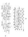
- FIG. 8 shows an example of the electrocardiogram synchronous measurement according to the present embodiment, in which the electrocardiographic waveform of the subject is detected and the R wave is used as a trigger signal in synchronization therewith.
- FIG. 8 (a) shows a trigger signal and echo signal measurement time table when a T2-weighted image is acquired.
- FIG. 8B shows a sequence chart of an example of a pulse sequence for echo signal measurement.
- Measurement control unit 4 activates a pulse sequence and performs echo signal measurement 802-1a after a predetermined time (Delay time) has elapsed since detection of trigger signal 801-1a.
- a pulse sequence as shown in FIG. 8B, a multi-echo type pulse sequence such as an FSE sequence or an EPI sequence capable of measuring a plurality of echo signals is used. Details will be described later.
- the measurement control unit 4 controls measurement of a predetermined number of echo signals based on such a pulse sequence.
- a number for example, 2, 3 heartbeats are used as a waiting time, and after this waiting time has elapsed, the pulse sequence is again detected after the trigger signal 801-1b is detected. Start up and perform echo signal measurement 802-1b.
- the measurement control unit 4 performs a process of measuring echo signals after Delay Time and waiting for a waiting time for several heartbeat cycles as a unit for each of a plurality of heartbeat cycles (here, three heartbeats).
- the measurement control unit 4 starts the pulse sequence after the same fixed time (Delay time) as the measurement of the partial region 201 has elapsed since the detection of the trigger signal 801-2a. Then, echo signal measurement 802-2a is performed.
- the waiting time after that is set shorter than when the echo signal in the divided area 201 is measured.
- the waiting time after the end of the pulse sequence is shortened by one heartbeat cycle compared to the case of the divided region 201.
- the present embodiment is not defined as one heartbeat cycle as the degree of shortening the waiting time, and can be arbitrarily set. After this waiting time, after detecting the trigger signal 801-2b again, the pulse sequence is activated to perform echo signal measurement 802-2b.
- the measurement control unit 4 uses, as a unit, the measurement of the echo signal after Delay Time and the waiting time for one or more heartbeat periods shorter than the echo signal measurement of the partial area 201.
- the measurement control unit 4 sets the waiting time after the pulse sequence operation to be shorter than that of the echo signal measurement of the divided area 202 to measure the echo signal. Shorten the cycle.
- the measurement control unit 4 starts the pulse sequence after the same fixed time (Delay time) as the measurement of the partial region 201 has elapsed since the detection of the trigger signal 801-3a. Then, echo signal measurement 802-3a is performed. The waiting time after that is set shorter than when the echo signal is measured in the divided area 202.
- Delay time the same fixed time
- the present embodiment provides an echo signal corresponding to a partial region on the high spatial frequency side by changing the waiting time for the repetition time (TR) of the pulse sequence for measuring the echo signal.
- the repetition time in the case of this measurement is shorter than the repetition time in the case of the measurement of the echo signal corresponding to the partial region on the low spatial frequency side.
- an echo signal is measured by repeating a multi-echo type pulse sequence for each one or more heartbeat cycles in accordance with the partial region.
- the pulse sequence is repeated every plural heartbeat cycles. Therefore, this embodiment is suitable for acquiring a T2-weighted image. Therefore, for example, an FSE sequence shown in FIG. 8B is used as a pulse sequence suitable for obtaining a T2-weighted image.
- RF, Gs, Gp, Gf, and Echo in the sequence chart shown in FIG. 8B are the same as those in FIG.
- the FSE sequence consists of a 180-degree RF pulse (516-1 to 516-6), slice gradient magnetic field (517-1 to 517-5), and frequency-encoded gradient magnetic field (519-1) shown in Fig. 5 (b).
- ⁇ 519-5) is repeated to measure multiple echo signals (520-1 to 520-5), before and after the measurement of each echo signal
- a pair of phase encoding gradient magnetic fields (801-1a, 801-1b to 801-5a, where 801-5b and 801-3 are zero application amounts) are applied by changing the application amount for each echo signal measurement. . Therefore, the phase encoding gradient magnetic field 518 is not applied.
- a plurality of echo signals (520-1 to 520-5) having different phase encodings can be measured by one 90-degree RF pulse 511.
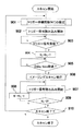
- FIG. 9 shows an outline of the operation flow of the present embodiment
- FIG. 10 particularly shows details of the processing in step 901.
- These processing flows are stored in the external storage device as programs, and are executed when the CPU 8 reads them into the memory and executes them as necessary.
- the operator inputs and sets the number of divisions in the three-dimensional K space, and the CPU 8 determines the K space according to the input set value. It is assumed that the number of divisions is determined.
- step 901 when the electrocardiogram synchronous measurement is started by the operator, the trigger signal standby frequency (NT) is set according to the partial area of the K space to be imaged. Details of this setting process will be described later with reference to FIG.
- step 902 after completing the setting of the trigger signal standby frequency (NT), the measurement control unit 4 starts reading the trigger signal.
- step 903 when receiving the trigger signal, the measurement control unit 4 subtracts 1 from the set trigger signal standby number (NT) in step 904.
- step 905 the measurement control unit 4 waits for a delay time (Td) set in advance. If the above-described blanking is performed during this Delay Time period, the intensity of the echo signal measured thereafter can be stabilized and a high-quality image can be obtained.
- Td delay time
- step 906 the measurement control unit 4 executes a pulse sequence as shown in FIG. 8B, for example, assuming that the time when the delay time (Td) has passed is the timing when the subject's movement is the least.
- step 910 when the waiting time is over, if the imaging is not finished, the process returns to step 901, the trigger signal waiting number (NT) is set again, and the above steps 901 to 909 are repeated until the imaging is finished.
- NT trigger signal waiting number
- the CPU 8 sets the trigger signal standby frequency (NT2) of the partial area 202 and the trigger signal standby frequency (NT3) of the partial area 203 based on the trigger signal standby frequency (NT1) when measuring the divided area 201.
- the trigger signal standby frequency (NT1) may be, for example, an operator setting the trigger signal standby frequency (NT1) or storing a predetermined value in advance.
- the number of trigger signal waiting times in the divided area 202 and the divided area 203 can be obtained by the following equation using, for example, an imaging speedup rate RapidRaRate set by the operator as an imaging parameter.
- NT2 NT1 ⁇ (1-Rapid Rate / 100)
- NT3 NT2 ⁇ (1-Rapid Rate / 100)
- the imaging speed-up rate Rapid Rate can be automatically calculated so that the Delay Time finally becomes the minimum value, for example, as in the first embodiment.
- step 1002 the CPU 8 determines whether or not the measurement of the echo signal of the partial area 202. If so, in step 1003, the number of trigger signal standby times of the partial area 202 obtained by equation (2) is determined. Set to the value NT2.
- step 1004 the CPU 8 determines whether or not the measurement of the echo signal of the partial area 203. If so, in step 1005, the number of times of waiting for the trigger signal in the partial area 203 obtained by the expression (2) is determined. Set to the value NT2.
- the three-dimensional K space is divided into a plurality of slice encoding directions, and an echo signal is generated according to the position of the divided partial region in the slice encoding direction. It is possible to shorten the imaging time by making the waiting time after measuring the difference. Specifically, the contrast of the three-dimensional image can be maintained in a desired state by setting the waiting time when measuring the echo signal of the partial region on the low spatial frequency side to be a desired image contrast. And the imaging time can be shortened by making the waiting time when measuring the echo signal of the partial area on the high spatial frequency side shorter than the waiting time when measuring the echo signal of the partial area on the low spatial frequency side. Can be done.
- each embodiment of the electrocardiogram synchronous measurement which concerns on the MRI apparatus and synchronous imaging method of this invention.
- the MRI apparatus and the synchronous imaging method of the present invention are not limited to the contents disclosed in the description of the above embodiments, and can take other forms based on the gist of the present invention.
- the delay time control for each partial area in the first embodiment may be combined with the waiting time control for each partial area in the second embodiment.
- a T2-weighted image may be acquired using an FSE sequence in the first embodiment, or a proton-weighted image may be acquired or a spin echo (SE) sequence may be used in the second embodiment.
- SE spin echo
- 1 subject 2 static magnetic field generation system, 3 gradient magnetic field generation system, 4 measurement control unit, 5 transmission system, 6 reception system, 7 signal processing system, 8 central processing unit (CPU), 9 gradient magnetic field coil, 10 gradient Magnetic field power supply, 11 high frequency oscillator, 12 modulator, 13 high frequency amplifier, 14a high frequency coil (transmitting coil), 14b high frequency coil (receiving coil), 15 signal amplifier, 16 quadrature phase detector, 17 A / D converter, 18 magnetic Disc, 19 optical disc, 20 display, 21 ROM, 22 RAM, 23 trackball or mouse, 24 keyboard, 51 gantry, 52 table, 53 housing, 54 processing device
Landscapes
- Health & Medical Sciences (AREA)
- Life Sciences & Earth Sciences (AREA)
- Physics & Mathematics (AREA)
- Engineering & Computer Science (AREA)
- Biophysics (AREA)
- Physiology (AREA)
- Nuclear Medicine, Radiotherapy & Molecular Imaging (AREA)
- General Health & Medical Sciences (AREA)
- Animal Behavior & Ethology (AREA)
- High Energy & Nuclear Physics (AREA)
- Heart & Thoracic Surgery (AREA)
- Medical Informatics (AREA)
- Molecular Biology (AREA)
- Surgery (AREA)
- Pathology (AREA)
- Radiology & Medical Imaging (AREA)
- Public Health (AREA)
- Veterinary Medicine (AREA)
- Signal Processing (AREA)
- Biomedical Technology (AREA)
- Computer Vision & Pattern Recognition (AREA)
- Psychiatry (AREA)
- Artificial Intelligence (AREA)
- Cardiology (AREA)
- Power Engineering (AREA)
- Pulmonology (AREA)
- Condensed Matter Physics & Semiconductors (AREA)
- General Physics & Mathematics (AREA)
- Magnetic Resonance Imaging Apparatus (AREA)
Abstract
Description
最初に、本発明に係るK空間の分割について説明する。本発明のMRI装置及び同期撮像方法は、被検体の周期的体動情報から検出したトリガー情報に同期した同期計測において、エコー信号の計測期間の、前に第1の期間と後に第2の期間の少なくとも一方を設ける。そして、K空間を複数の部分領域に分割し、低空間周波数側の部分領域に対応するエコー信号の計測と、高空間周波数側の部分領域に対応するエコー信号の計測とで、第1の期間と第2の期間の少なくとも一方を異ならせる。
次に、本発明のMRI装置及び同期撮像方法の第1の実施形態を説明する。本実施形態は、第1の期間として、トリガー情報とエコー信号の計測期間との間にディレイ時間を設定し、高空間周波数側の部分領域に対応するエコー信号の計測におけるディレイ時間を、低空間周波側の部分領域に対応するエコー信号の計測におけるディレイ時間よりも短くする。本実施形態は、例えばT1強調画像の取得に好適である。以下、図5~図7に基づいて本実施形態を説明する。
N3=N2×(1+Rapid Rate/100), Td3=Td2+TR×(N3-N2)
撮像高速化率Rapid Rateは、例えば、最終的にDelay Timeが最小値となるように、つまり、最後の部分領域(この場合では部分領域203)のエコー信号計測時のDelay Timeが最小値となるように、自動的に算出することも可能である。
次に、本発明のMRI装置及び同期撮像方法の第2の実施形態を説明する。本実施形態は、第2の期間として、一つのエコー信号計測期間から、次のエコー信号計測期間のトリガーとなるトリガー情報までの待ち時間を設定し、高空間周波数側の部分領域に対応するエコー信号の計測における待ち時間を、低空間周波数側の部分領域に対応するエコー信号の計測における待ち時間よりも短くする。好ましくは、周期的体動の一周期の整数倍だけ、待ち時間を異ならせる。すなわち、エコー信号の計測を行うためのパルスシーケンスの繰り返し時間について、高空間周波数側の部分領域に対応するエコー信号の計測の場合の繰り返し時間を、低空間周波数側の部分領域に対応するエコー信号の計測の場合の繰り返し時間よりも短くする。本実施形態は、例えばT2強調画像の取得に好適である。以下、前述の第1の実施形態と異なる点のみを図8~図10に基づいて説明し、同じ点の説明は省略する。
NT3=NT2×(1-Rapid Rate/100)
撮像高速化率Rapid Rateは、例えば、前述の第1の実施形態と同様に、最終的にDelay Timeが最小値となるように自動的に算出することも可能である。
Claims (18)
- 被検体の周期的体動情報からトリガー情報を検出する検出部と、
前記トリガー情報に同期して前記被検体からのエコー信号を計測する同期計測を制御する計測制御部と、
前記エコー信号のデータがK空間に配置されて成るK空間データに基づいて、前記被検体の画像を取得する演算処理部と、
を備え、
前記同期計測は、前記エコー信号の計測期間の、前に第1の期間と後に第2の期間の少なくとも一方を設けた磁気共鳴イメージング装置であって、
前記演算処理部は、前記K空間を複数の部分領域に分割し、
前記計測制御部は、低空間周波数側の部分領域に対応するエコー信号の計測と、高空間周波数側の部分領域に対応するエコー信号の計測とで、前記第1の期間と前記第2の期間の少なくとも一方を異ならせることを特徴とする磁気共鳴イメージング装置。 - 請求項1記載の磁気共鳴イメージング装置において、
前記K空間はスライスエンコード方向と位相エンコード方向を含む3次元空間であり、前記K空間の分割はスライスエンコード方向に行われることを特徴とする磁気共鳴イメージング装置。 - 請求項1記載の磁気共鳴イメージング装置において、
前記計測制御部は、前記第1の期間として、前記トリガー情報と前記エコー信号の計測期間との間にディレイ時間を設けることを特徴とする磁気共鳴イメージング装置。 - 請求項3記載の磁気共鳴イメージング装置において、
前記計測制御部は、前記高空間周波数側の部分領域に対応するエコー信号の計測における前記ディレイ時間を、前記低空間周波側の部分領域に対応するエコー信号の計測における前記ディレイ時間よりも短くすることを特徴とする磁気共鳴イメージング装置。 - 請求項3記載の磁気共鳴イメージング装置において、
前記計測制御部は、前記部分領域に対応するエコー信号の計測を、1心拍動周期毎に繰り返すことを特徴とする磁気共鳴イメージング装置。 - 請求項1記載の磁気共鳴イメージング装置において、
前記計測制御部は、前記第2の期間として、一つのエコー信号計測期間から、次のエコー信号計測期間のトリガーとなるトリガー情報までの待ち時間を設けることを特徴とする磁気共鳴イメージング装置。 - 請求項6記載の磁気共鳴イメージング装置において、
前記計測制御部は、前記高空間周波数側の部分領域に対応するエコー信号の計測における前記待ち時間を、前記低空間周波数側の部分領域に対応するエコー信号の計測における前記待ち時間よりも短くすることを特徴とする磁気共鳴イメージング装置。 - 請求項6記載の磁気共鳴イメージング装置において、
前記計測制御部は、前記周期的体動の一周期の整数倍だけ、前記待ち時間を異ならせることを特徴とする磁気共鳴イメージング装置。 - 請求項6記載の磁気共鳴イメージング装置において、
前記計測制御部は、前記低空間周波数側の部分領域に対応するエコー信号の計測を、複数心拍動周期毎に繰り返すことを特徴とする磁気共鳴イメージング装置。 - 請求項6記載の磁気共鳴イメージング装置において、
前記計測制御部は、前記第1の期間として、前記トリガー情報と前記エコー信号の計測期間との間にディレイ時間を設け、前記部分領域に依らずに、前記ディレイ時間を同じにすることを特徴とする磁気共鳴イメージング装置。 - 請求項1記載の磁気共鳴イメージング装置において、
前記計測制御部は、前記エコー信号の計測を行うためのパルスシーケンスの繰り返し時間について、前記高空間周波数側の部分領域に対応するエコー信号の計測の場合の繰り返し時間を、前記低空間周波数側の部分領域に対応するエコー信号の計測の場合の繰り返し時間よりも短くすることを特徴とする磁気共鳴イメージング装置。 - 請求項3記載の磁気共鳴イメージング装置において、
前記計測制御部は、スピンエコーシーケンスを用いて前記エコー信号の計測を行うことを特徴とする磁気共鳴イメージング装置。 - 請求項6記載の磁気共鳴イメージング装置において、
前記計測制御部は、マルチエコータイプのパルスシーケンスを用いて前記エコー信号の計測を行うことを特徴とする磁気共鳴イメージング装置。 - 請求項1記載の磁気共鳴イメージング装置において、
前記K空間を複数の部分領域に分割するための分割数と、少なくとも一つの部分領域の前記K空間に対する割合の設定を受け付ける入力設定部を備えたことを特徴とする磁気共鳴イメージング装置。 - 被検体の周期的体動情報からトリガー情報を検出する検出工程と、
前記トリガー情報に同期して前記被検体からのエコー信号を計測する同期計測を制御する計測制工程と、
前記エコー信号を用いて、前記被検体の画像を取得する演算処理工程と、
を備え、
前記同期計測は、前記エコー信号の計測期間の、前に第1の期間と後に第2の期間の少なくとも一方を設けた同期撮像方法であって、
前記エコー信号のデータが配置されるK空間を複数の部分領域に分割する工程を更に備え、
前記計測制御工程は、低空間周波数側の部分領域に対応するエコー信号の計測と、高空間周波数側の部分領域に対応するエコー信号の計測とで、前記第1の期間と前記第2の期間の少なくとも一方を異ならせることを特徴とする同期撮像方法。 - 請求項15記載の同期撮像方法において、
前記計測制御工程は、前記第1の期間として、前記トリガー情報と前記エコー信号の計測期間との間にディレイ時間を設けることを特徴とする同期撮像方法。 - 請求項15記載の同期撮像方法において、
前記計測制御工程は、前記第2の期間として、一つのエコー信号計測期間から、次のエコー信号計測期間のトリガーとなるトリガー情報までの待ち時間を設けることを特徴とする同期撮像方法。 - 請求項15記載の同期撮像方法において、
前記計測制御工程は、前記エコー信号の計測を行うためのパルスシーケンスの繰り返し時間について、前記高空間周波数側の部分領域に対応するエコー信号の計測の場合の繰り返し時間を、前記低空間周波数側の部分領域に対応するエコー信号の計測の場合の繰り返し時間よりも短くすることを特徴とする同期撮像方法。
Priority Applications (3)
| Application Number | Priority Date | Filing Date | Title |
|---|---|---|---|
| US13/132,163 US20110237931A1 (en) | 2008-12-04 | 2009-11-26 | Magnetic resonance imaging apparatus and synchronous imaging method |
| JP2010541301A JP5372015B2 (ja) | 2008-12-04 | 2009-11-26 | 磁気共鳴イメージング装置および同期撮像方法 |
| CN2009801487337A CN102238909B (zh) | 2008-12-04 | 2009-11-26 | 磁共振成像装置以及同步摄像方法 |
Applications Claiming Priority (2)
| Application Number | Priority Date | Filing Date | Title |
|---|---|---|---|
| JP2008-309192 | 2008-12-04 | ||
| JP2008309192 | 2008-12-04 |
Publications (1)
| Publication Number | Publication Date |
|---|---|
| WO2010064572A1 true WO2010064572A1 (ja) | 2010-06-10 |
Family
ID=42233223
Family Applications (1)
| Application Number | Title | Priority Date | Filing Date |
|---|---|---|---|
| PCT/JP2009/069945 Ceased WO2010064572A1 (ja) | 2008-12-04 | 2009-11-26 | 磁気共鳴イメージング装置および同期撮像方法 |
Country Status (4)
| Country | Link |
|---|---|
| US (1) | US20110237931A1 (ja) |
| JP (1) | JP5372015B2 (ja) |
| CN (1) | CN102238909B (ja) |
| WO (1) | WO2010064572A1 (ja) |
Families Citing this family (6)
| Publication number | Priority date | Publication date | Assignee | Title |
|---|---|---|---|---|
| JP5372015B2 (ja) * | 2008-12-04 | 2013-12-18 | 株式会社日立メディコ | 磁気共鳴イメージング装置および同期撮像方法 |
| CN103185876B (zh) * | 2011-12-30 | 2015-05-13 | 西门子(深圳)磁共振有限公司 | 磁共振成像方法及磁共振成像装置 |
| JP6151697B2 (ja) * | 2012-08-13 | 2017-06-21 | 株式会社日立製作所 | 磁気共鳴イメージング装置及び磁気共鳴イメージング方法 |
| DE102012216773B4 (de) * | 2012-09-19 | 2018-11-08 | Siemens Healthcare Gmbh | Aufnahme von mindestens zwei Messdatensätzen eines Untersuchungsobjekts mittels einer Magnetresonanzanlage |
| CN108567422B (zh) * | 2018-03-02 | 2021-03-05 | 上海东软医疗科技有限公司 | 一种血管成像方法和装置 |
| CN113644920B (zh) * | 2021-06-16 | 2022-10-14 | 北京协同创新研究院 | 一种用于脑部成像的微波多路收发系统 |
Citations (1)
| Publication number | Priority date | Publication date | Assignee | Title |
|---|---|---|---|---|
| JP2002200054A (ja) * | 2000-12-27 | 2002-07-16 | Toshiba Corp | Mri装置及びmrイメージング方法 |
Family Cites Families (9)
| Publication number | Priority date | Publication date | Assignee | Title |
|---|---|---|---|---|
| DE19901171C2 (de) * | 1999-01-14 | 2001-12-13 | Axel Haase | Verfahren und Vorrichtung zum Gewinnen von Daten für Magnetresonanz-Bildgebung |
| US6801800B2 (en) * | 1999-11-29 | 2004-10-05 | Kabushiki Kaisha Toshiba | MR imaging using ECG-prep scan |
| US6611701B2 (en) * | 2000-12-30 | 2003-08-26 | Ge Medical Systems Global Technology Company, Llc | Method and apparatus for fast breath-held 3D MR data acquisition using variable sampling |
| EP2202530B1 (en) * | 2005-09-19 | 2013-11-06 | Kabushiki Kaisha Toshiba | MRI involving retrospective data extraction |
| US7840045B2 (en) * | 2006-04-21 | 2010-11-23 | The University Of Utah Research Foundation | Method and system for parallel reconstruction in the K-space domain for application in imaging systems |
| US9020575B2 (en) * | 2006-11-10 | 2015-04-28 | Kabushiki Kaisha Toshiba | Magnetic resonance imaging apparatus and magnetic resonance imaging method |
| JP5269381B2 (ja) * | 2006-11-10 | 2013-08-21 | 株式会社東芝 | 磁気共鳴イメージング装置および磁気共鳴イメージング方法 |
| JP5019576B2 (ja) * | 2006-11-24 | 2012-09-05 | 株式会社東芝 | 磁気共鳴イメージング装置 |
| JP5372015B2 (ja) * | 2008-12-04 | 2013-12-18 | 株式会社日立メディコ | 磁気共鳴イメージング装置および同期撮像方法 |
-
2009
- 2009-11-26 JP JP2010541301A patent/JP5372015B2/ja not_active Expired - Fee Related
- 2009-11-26 WO PCT/JP2009/069945 patent/WO2010064572A1/ja not_active Ceased
- 2009-11-26 US US13/132,163 patent/US20110237931A1/en not_active Abandoned
- 2009-11-26 CN CN2009801487337A patent/CN102238909B/zh not_active Expired - Fee Related
Patent Citations (1)
| Publication number | Priority date | Publication date | Assignee | Title |
|---|---|---|---|---|
| JP2002200054A (ja) * | 2000-12-27 | 2002-07-16 | Toshiba Corp | Mri装置及びmrイメージング方法 |
Also Published As
| Publication number | Publication date |
|---|---|
| US20110237931A1 (en) | 2011-09-29 |
| JP5372015B2 (ja) | 2013-12-18 |
| CN102238909A (zh) | 2011-11-09 |
| JPWO2010064572A1 (ja) | 2012-05-10 |
| CN102238909B (zh) | 2013-09-04 |
Similar Documents
| Publication | Publication Date | Title |
|---|---|---|
| JP5002222B2 (ja) | 磁気共鳴イメージング装置 | |
| JP5917077B2 (ja) | 磁気共鳴イメージング装置 | |
| JP6467341B2 (ja) | 磁気共鳴イメージング装置、画像処理装置、画像診断装置、画像解析装置、mri画像作成方法およびプログラム | |
| JP2014511742A (ja) | Mrデータを収集する方法及び装置 | |
| JP6708525B2 (ja) | 磁気共鳴測定装置および画像処理方法 | |
| EP2335572A1 (en) | Magnetic resonance imaging apparatus, and breath-holding imaging method | |
| US20120281901A1 (en) | Magnetic resonance imaging apparatus and blood vessel image capturing method | |
| JP5372015B2 (ja) | 磁気共鳴イメージング装置および同期撮像方法 | |
| US9301704B2 (en) | Magnetic resonance imaging system for non-contrast MRA and magnetic resonance signal acquisition method employed by the same | |
| JP5536665B2 (ja) | 磁気共鳴イメージング装置及び磁気共鳴イメージング方法 | |
| US8594767B2 (en) | Magnetic resonance imaging apparatus and magnetic resonance imaging method | |
| KR101541290B1 (ko) | 자기 공명 신호 측정 방법 및 장치 | |
| JP2009279238A (ja) | 磁気共鳴イメージング装置 | |
| JP4230875B2 (ja) | 磁気共鳴イメージング装置 | |
| JP5336731B2 (ja) | 磁気共鳴イメージング装置 | |
| JP2007190114A (ja) | 磁気共鳴イメージング装置 | |
| JP5371620B2 (ja) | 核磁気共鳴イメージング装置 | |
| JP5319835B2 (ja) | 磁気共鳴イメージング装置 | |
| JP5421600B2 (ja) | 核磁気共鳴イメージング装置および核磁気共鳴イメージング装置の作動方法 | |
| JP2015002834A (ja) | 磁気共鳴イメージング装置及び磁気共鳴イメージング方法 | |
| JP4018107B2 (ja) | 磁気共鳴イメージング装置 | |
| JP6157976B2 (ja) | 磁気共鳴イメージング装置、及び方法 | |
| JP4994786B2 (ja) | 磁気共鳴イメージング装置 | |
| JP5284422B2 (ja) | 磁気共鳴イメージング装置 | |
| JP5514293B2 (ja) | 磁気共鳴イメージング装置 |
Legal Events
| Date | Code | Title | Description |
|---|---|---|---|
| WWE | Wipo information: entry into national phase |
Ref document number: 200980148733.7 Country of ref document: CN |
|
| 121 | Ep: the epo has been informed by wipo that ep was designated in this application |
Ref document number: 09830339 Country of ref document: EP Kind code of ref document: A1 |
|
| ENP | Entry into the national phase |
Ref document number: 2010541301 Country of ref document: JP Kind code of ref document: A |
|
| WWE | Wipo information: entry into national phase |
Ref document number: 13132163 Country of ref document: US |
|
| NENP | Non-entry into the national phase |
Ref country code: DE |
|
| 122 | Ep: pct application non-entry in european phase |
Ref document number: 09830339 Country of ref document: EP Kind code of ref document: A1 |