WO2010061840A1 - Mold device for two-color molding and two-color molded article - Google Patents
Mold device for two-color molding and two-color molded article Download PDFInfo
- Publication number
- WO2010061840A1 WO2010061840A1 PCT/JP2009/069840 JP2009069840W WO2010061840A1 WO 2010061840 A1 WO2010061840 A1 WO 2010061840A1 JP 2009069840 W JP2009069840 W JP 2009069840W WO 2010061840 A1 WO2010061840 A1 WO 2010061840A1
- Authority
- WO
- WIPO (PCT)
- Prior art keywords
- molded product
- film
- mold
- primary
- cavity
- Prior art date
Links
Images


Classifications
-
- B—PERFORMING OPERATIONS; TRANSPORTING
- B29—WORKING OF PLASTICS; WORKING OF SUBSTANCES IN A PLASTIC STATE IN GENERAL
- B29C—SHAPING OR JOINING OF PLASTICS; SHAPING OF MATERIAL IN A PLASTIC STATE, NOT OTHERWISE PROVIDED FOR; AFTER-TREATMENT OF THE SHAPED PRODUCTS, e.g. REPAIRING
- B29C45/00—Injection moulding, i.e. forcing the required volume of moulding material through a nozzle into a closed mould; Apparatus therefor
- B29C45/16—Making multilayered or multicoloured articles
- B29C45/1671—Making multilayered or multicoloured articles with an insert
-
- B—PERFORMING OPERATIONS; TRANSPORTING
- B29—WORKING OF PLASTICS; WORKING OF SUBSTANCES IN A PLASTIC STATE IN GENERAL
- B29C—SHAPING OR JOINING OF PLASTICS; SHAPING OF MATERIAL IN A PLASTIC STATE, NOT OTHERWISE PROVIDED FOR; AFTER-TREATMENT OF THE SHAPED PRODUCTS, e.g. REPAIRING
- B29C45/00—Injection moulding, i.e. forcing the required volume of moulding material through a nozzle into a closed mould; Apparatus therefor
- B29C45/0025—Preventing defects on the moulded article, e.g. weld lines, shrinkage marks
-
- B—PERFORMING OPERATIONS; TRANSPORTING
- B29—WORKING OF PLASTICS; WORKING OF SUBSTANCES IN A PLASTIC STATE IN GENERAL
- B29C—SHAPING OR JOINING OF PLASTICS; SHAPING OF MATERIAL IN A PLASTIC STATE, NOT OTHERWISE PROVIDED FOR; AFTER-TREATMENT OF THE SHAPED PRODUCTS, e.g. REPAIRING
- B29C45/00—Injection moulding, i.e. forcing the required volume of moulding material through a nozzle into a closed mould; Apparatus therefor
- B29C45/17—Component parts, details or accessories; Auxiliary operations
- B29C45/26—Moulds
- B29C45/37—Mould cavity walls, i.e. the inner surface forming the mould cavity, e.g. linings
-
- B—PERFORMING OPERATIONS; TRANSPORTING
- B29—WORKING OF PLASTICS; WORKING OF SUBSTANCES IN A PLASTIC STATE IN GENERAL
- B29C—SHAPING OR JOINING OF PLASTICS; SHAPING OF MATERIAL IN A PLASTIC STATE, NOT OTHERWISE PROVIDED FOR; AFTER-TREATMENT OF THE SHAPED PRODUCTS, e.g. REPAIRING
- B29C45/00—Injection moulding, i.e. forcing the required volume of moulding material through a nozzle into a closed mould; Apparatus therefor
- B29C45/14—Injection moulding, i.e. forcing the required volume of moulding material through a nozzle into a closed mould; Apparatus therefor incorporating preformed parts or layers, e.g. injection moulding around inserts or for coating articles
- B29C2045/1486—Details, accessories and auxiliary operations
- B29C2045/14901—Coating a sheet-like insert smaller than the dimensions of the adjacent mould wall
-
- B—PERFORMING OPERATIONS; TRANSPORTING
- B29—WORKING OF PLASTICS; WORKING OF SUBSTANCES IN A PLASTIC STATE IN GENERAL
- B29C—SHAPING OR JOINING OF PLASTICS; SHAPING OF MATERIAL IN A PLASTIC STATE, NOT OTHERWISE PROVIDED FOR; AFTER-TREATMENT OF THE SHAPED PRODUCTS, e.g. REPAIRING
- B29C45/00—Injection moulding, i.e. forcing the required volume of moulding material through a nozzle into a closed mould; Apparatus therefor
- B29C45/16—Making multilayered or multicoloured articles
- B29C2045/1682—Making multilayered or multicoloured articles preventing defects
-
- B—PERFORMING OPERATIONS; TRANSPORTING
- B29—WORKING OF PLASTICS; WORKING OF SUBSTANCES IN A PLASTIC STATE IN GENERAL
- B29C—SHAPING OR JOINING OF PLASTICS; SHAPING OF MATERIAL IN A PLASTIC STATE, NOT OTHERWISE PROVIDED FOR; AFTER-TREATMENT OF THE SHAPED PRODUCTS, e.g. REPAIRING
- B29C45/00—Injection moulding, i.e. forcing the required volume of moulding material through a nozzle into a closed mould; Apparatus therefor
- B29C45/14—Injection moulding, i.e. forcing the required volume of moulding material through a nozzle into a closed mould; Apparatus therefor incorporating preformed parts or layers, e.g. injection moulding around inserts or for coating articles
- B29C45/14778—Injection moulding, i.e. forcing the required volume of moulding material through a nozzle into a closed mould; Apparatus therefor incorporating preformed parts or layers, e.g. injection moulding around inserts or for coating articles the article consisting of a material with particular properties, e.g. porous, brittle
-
- B—PERFORMING OPERATIONS; TRANSPORTING
- B29—WORKING OF PLASTICS; WORKING OF SUBSTANCES IN A PLASTIC STATE IN GENERAL
- B29C—SHAPING OR JOINING OF PLASTICS; SHAPING OF MATERIAL IN A PLASTIC STATE, NOT OTHERWISE PROVIDED FOR; AFTER-TREATMENT OF THE SHAPED PRODUCTS, e.g. REPAIRING
- B29C45/00—Injection moulding, i.e. forcing the required volume of moulding material through a nozzle into a closed mould; Apparatus therefor
- B29C45/16—Making multilayered or multicoloured articles
- B29C45/1615—The materials being injected at different moulding stations
- B29C45/162—The materials being injected at different moulding stations using means, e.g. mould parts, for transferring an injected part between moulding stations
-
- B—PERFORMING OPERATIONS; TRANSPORTING
- B29—WORKING OF PLASTICS; WORKING OF SUBSTANCES IN A PLASTIC STATE IN GENERAL
- B29L—INDEXING SCHEME ASSOCIATED WITH SUBCLASS B29C, RELATING TO PARTICULAR ARTICLES
- B29L2031/00—Other particular articles
- B29L2031/34—Electrical apparatus, e.g. sparking plugs or parts thereof
- B29L2031/3431—Telephones, Earphones
- B29L2031/3437—Cellular phones
-
- Y—GENERAL TAGGING OF NEW TECHNOLOGICAL DEVELOPMENTS; GENERAL TAGGING OF CROSS-SECTIONAL TECHNOLOGIES SPANNING OVER SEVERAL SECTIONS OF THE IPC; TECHNICAL SUBJECTS COVERED BY FORMER USPC CROSS-REFERENCE ART COLLECTIONS [XRACs] AND DIGESTS
- Y10—TECHNICAL SUBJECTS COVERED BY FORMER USPC
- Y10T—TECHNICAL SUBJECTS COVERED BY FORMER US CLASSIFICATION
- Y10T428/00—Stock material or miscellaneous articles
- Y10T428/18—Longitudinally sectional layer of three or more sections
- Y10T428/183—Next to unitary sheet of equal or greater extent
-
- Y—GENERAL TAGGING OF NEW TECHNOLOGICAL DEVELOPMENTS; GENERAL TAGGING OF CROSS-SECTIONAL TECHNOLOGIES SPANNING OVER SEVERAL SECTIONS OF THE IPC; TECHNICAL SUBJECTS COVERED BY FORMER USPC CROSS-REFERENCE ART COLLECTIONS [XRACs] AND DIGESTS
- Y10—TECHNICAL SUBJECTS COVERED BY FORMER USPC
- Y10T—TECHNICAL SUBJECTS COVERED BY FORMER US CLASSIFICATION
- Y10T428/00—Stock material or miscellaneous articles
- Y10T428/19—Sheets or webs edge spliced or joined
- Y10T428/192—Sheets or webs coplanar
Definitions
- the present invention relates to a two-color molding tool and a two-color molded product for molding and integrating a molded product by dividing the process into two stages of primary molding and secondary molding.
- a primary molded product is molded using a primary side mold, and after taking out the primary molded product, it is directly set on the secondary side mold to perform secondary molding.
- a two-color molded product is manufactured by integrating the secondary molded product and the secondary molded product.
- a molded product with a film can be obtained simultaneously with molding, and so-called in-mold molding can be performed.
- a pattern can be provided on the surface of the molded product simultaneously with molding.
- a functional film on which an electric circuit is formed is used, the molded product is molded simultaneously with molding.
- An electric circuit can be formed therein.
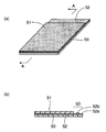
- FIG. 5A shows a conventional two-color molded product in which a functional film 52 is embedded and integrated between a primary molded product 50 and a secondary molded product 51.
- a signal extraction attachment region 53 is required as shown in FIG. 5B showing the AA cross section of FIG.
- the size of the secondary molded product 51 is formed to be smaller than that of the primary molded product 50, and a part of the functional film 52 (film end portion 52 a) is placed on the upper surface in a range corresponding to the attachment region 52 It was exposed to the side.
- a cable such as FPC (Flexible Printed Circuits) is always taken out from the upper surface side of the secondary molded product 51.
- 52b indicates a terminal for FPC connection.
- the secondary molded product 51 in the two-color molding is often used as an exterior of the product, and in this case, it is desirable to move the cable out to the lower surface side of the secondary molded product 51.
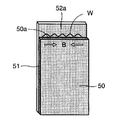
- the film end in the attachment region 52a protrudes from the edge 50a of the primary molded product 50 in a band shape, and the primary molded product 50 is molded and contracted, while the film end 52a that is not in contact with the molten resin does not contract.
- a wavy (wrinkle) W is generated at the film end 52a.
- the present invention has been made in consideration of the problems that occur when in-molding a film in the two-color molding as described above. Two colors that can be in-molded in a two-color molded product without undulating the film. A mold apparatus for molding and a two-color molded product are provided.
- the present invention comprises forming a primary molded product by injecting a resin into a first cavity formed by closing a mold of both molds by making a film in a primary mold composed of a fixed mold and a movable mold, The formed primary molded product with a film is moved to a secondary mold composed of a fixed mold and a movable mold, and a resin is injected into a second cavity formed by closing the molds of both molds.
- the first cavity is configured to mold the primary molded product having a size smaller than the film so that a part of the film protrudes from the primary molded product.
- a convexity that restricts the molding shrinkage of the film protruding side in the primary molded product is formed on the cavity-forming wall surface that is located on the protruding side of the film and forms the first cavity. It is a mold device.
- the first cavity has a rectangular shape when viewed from the mold closing direction, and has concave portions on both sides of the convex portion, and these concave portions are located at both ends of the wall surface for forming the first cavity. preferable.
- the second cavity has a size capable of forming a secondary molded product covering substantially the entire surface of the film.
- the film can be composed of a functional film on which an electric circuit or the like is formed, and the electric circuit is preferably formed on a surface opposite to the surface on which the secondary molded product is laminated.
- the present invention is interposed between a primary molded product molded by primary molding, a secondary molded product molded over the primary molded product by secondary molding, and both molded products.
- the secondary molded product is formed to have substantially the same size as the film, and the primary molded product is such that a part of the functional film protrudes from the secondary molded product.
- the two-color molded product is formed in a smaller size, and the exposed surface of the functional film protruding portion constitutes a signal extraction portion for extracting a signal from the functional film.
- the outer surface of the housing part can be constituted by the secondary molded product.
- the present invention has the advantage that it can be in-molded into a two-color molded product without undulating the film.
- FIG. 1 It is a front longitudinal cross-sectional view of the die apparatus for two-color molding of this invention.
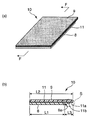
- (a) is a perspective view showing a configuration of a two-color molded product of the present invention, and (b) is a cross-sectional view taken along line FF in FIG. 2 (a).
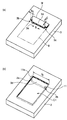
- (a) And (b) is a perspective view which shows the structure of the primary side metal mold
- (a)-(c) is explanatory drawing which shows the modification of the convex part shown in FIG.
- (a) is a perspective view showing the configuration of a conventional two-color molded product, and (b) is a cross-sectional view taken along the line AA in FIG. 5 (a). It is a perspective view explaining the corrugation which generate
- FIG. 1 is a front longitudinal sectional view showing a configuration of a two-color molding mold apparatus of the present invention.
- a two-color molding die apparatus 1 has a fixed mold 2 and a movable mold 3 that can be moved back and forth with respect to the fixed mold 2.
- the first cavity C1 for molding the second cavity C2 and the second cavity C2 for molding the secondary molded product are formed.
- a rectangular recess is formed in the fixed mold 2 corresponding to the first cavity C1, and the first cavity C1 communicates with a first injection nozzle 4 of a first injection machine (not shown) via a sprue. ing.
- the fixed mold 2 corresponding to the second cavity C2 is also formed with a rectangular recess, and the second cavity C2 communicates with a second injection nozzle 5 of a second injection machine (not shown) via a sprue. is doing.
- PC polycarbonate resin
- PMMA polymethyl methacrylate resin
- PC / PET polymer alloy of polycarbonate resin and polyethylene terephthalate resin
- a resin having the same color as that of the primary molding resin can be used as the secondary molding resin.
- the movable mold 3 can be rotated around the horizontal axis D (in the direction of arrow E) by the rotating disk 7 of the mold rotating mechanism 6.
- the movable mold 3 rotates in the direction of arrow E, the primary molded product 8 molded on the first cavity C1 side moves to the second cavity C2 side, and the secondary mold on the second cavity C2 side.
- a two-color molded product 10 in which the primary molded product and the secondary molded product are integrated is obtained.
- the fixed mold 2 and the movable mold 3 constituting the first cavity C1 function as a primary mold, and the fixed mold 2 and the movable mold 3 constituting the second cavity C2 function as a secondary mold.
- the two-color molded product 10 is molded by the above-described two-color molding mold apparatus 1, when the functional film (film) 11 on which an electric circuit or the like is formed is in-molded, the fixed mold 2 and the movable mold 3 are arranged. Primary molding is performed in a state where the functional film 11 is sandwiched between the two.
- FIG. 2 shows the configuration of a two-color molded product 10 formed by in-molding the functional film 11, wherein FIG. 2 (a) is a perspective view and FIG. 2 (b).
- FIG. 2 shows a cross-sectional view taken along the line FF in FIG.
- a two-color molded product 10 includes a primary molded product 8 formed into a rectangular shape by primary molding, a secondary molded product 9 formed into a rectangular shape by secondary molding, and both moldings. It is comprised from the functional film 11 interposed between goods.
- the primary molded product 8 As shown in FIG. 2B, by forming the primary molded product 8 with a length shorter than the length L2 in the longitudinal direction of the secondary molded product 9, one edge portion 8a of the primary molded product 8 is obtained. A part of the functional film 11 protrudes in the form of a band, and the length L3 of the film protruding part 11a is an attachment region S for taking out a signal from the electric circuit formed on the functional film 11.
- the secondary molded product 9 in the two-color molded product 10 constitutes the outer surface of the casing component of the mobile phone. Therefore, in the configuration of the two-color molded product 10, since the attachment region S is located on the inner surface side of the secondary molded product 9, a signal from the functional film 11 is transmitted to the housing component via the electrode 11 b of the film protruding portion 11 a. It can be taken out from the inner surface rather than the outer surface. That is, the protruding portion 11a constitutes a signal extraction portion for extracting a signal from the inner surface side.
- FIG. 3 is a perspective view showing the configuration of the primary side mold for molding the two-color molded product 10, and FIG. 3A shows the configuration of the movable mold 3.
- FIG. 2B shows the configuration of the fixed mold 2.
- a recess for forming a rectangular and thin plate-shaped primary molded product 8 is formed in the fixed mold 2, and a functional film 11 (reference numeral 11) is formed on the bottom surface of the recess during the primary molding. (See the range of the two-dot chain line).
- the functional film 11 is arrange
- the space C1 indicates the first cavity.
- a raised portion 3f that can be fitted into the recess is formed at a portion of the movable mold 3 corresponding to the film protruding portion 11a.
- the widths W1 of the notches 3b and 3c are preferably set in the range of 2 to 10% of the width W of the first cavity C1, and the depth lengths W2 of the notches 3b and 3c are set to the width W1. It is preferable to set it within the range of 1 to 10%.
- FIG. 4 shows a modification of the raised portion 3f.
- FIG. 5A shows a cavity forming wall surface 3a in the raised portion 3f formed in an arc shape.
- FIG. 5B shows another example in which another notch 3e is provided in the middle of the cavity forming wall 3a in the raised portion 3f, and the raised portion 3f is formed in a comb-like shape as a whole.
- the convex portion 3d of the raised portion 3f is formed in an inverted wedge shape. Specifically, the width of the cavity forming wall surface 3a in the convex portion 3d is wider than the width of the skirt portion of the convex portion 3d. Is.
- the molding shrinkage (arrow B direction) is regulated by interrupting the primary molding resin injected in the vicinity of the film protruding portion 11a. If it can do, the protruding part 3f can be comprised from arbitrary shapes.
- the functional film 11 is disposed in the first cavity C1, both molds are closed, and the primary molding resin is injected from the first injection nozzle 4 into the first cavity C1.
- the molding shrinkage of the primary molded product 8 starts.
- the raised portion 3f is formed on the movable mold 3 corresponding to the film protruding portion 11a. Since the convex portion 3d is formed on the cavity forming wall surface 3a of the protruding portion 3f, the primary molded product portion injected and molded into the concave portions 2a and 2b is restricted in molding shrinkage in the arrow B direction. Is done. Thereby, the lateral width of the primary molded product 8 that is injected into the first cavity C1 and molded is maintained at the same value as the lateral width W of the first cavity C1.
- the fixed mold 2 and the movable mold 3 are opened.
- the primary molded product 8 with the film 11 is now opposed to the second cavity C2 as the movable mold 3 rotates in the direction of arrow D.
- the film protruding portion 11a of the functional film 11 to be bonded to the primary molded product 8 is not affected by the molding shrinkage of the primary molded product during the primary molding, and thus is affected by the undulation. Secondary molding can be performed without any problem, and the two-color molded product 10 can be molded.
- the mold apparatus for two-color molding of the present invention is used as a method for incorporating metal parts such as wiring into a resin molded exterior part such as a mobile phone, PDA (personal digital assistant), portable game machine, etc. and integrating them. be able to.
Abstract
Description
上記第1キャビティは、上記1次成形品から上記フィルムの一部がはみ出すように上記フィルムよりも小さいサイズの上記1次成形品を成形するように構成され、
上記フィルムはみ出し側に位置しており上記第1キャビティを形成するキャビティ形成用の壁面に、上記1次成形品における上記フィルムはみ出し側の成形収縮を規制する凸部が形成されている2色成形用金型装置である。 The present invention comprises forming a primary molded product by injecting a resin into a first cavity formed by closing a mold of both molds by making a film in a primary mold composed of a fixed mold and a movable mold, The formed primary molded product with a film is moved to a secondary mold composed of a fixed mold and a movable mold, and a resin is injected into a second cavity formed by closing the molds of both molds. In a two-color mold apparatus for molding a molded product to obtain a two-color molded product in which the film is sandwiched and integrated between the primary molded product and the secondary molded product,
The first cavity is configured to mold the primary molded product having a size smaller than the film so that a part of the film protrudes from the primary molded product.
For the two-color molding, a convexity that restricts the molding shrinkage of the film protruding side in the primary molded product is formed on the cavity-forming wall surface that is located on the protruding side of the film and forms the first cavity. It is a mold device.
図1は、本発明の2色成形用金型装置の構成を示した正面縦断面図である。 1. Two-color molding mold apparatus FIG. 1 is a front longitudinal sectional view showing a configuration of a two-color molding mold apparatus of the present invention.
図2は、上記機能フィルム11をインモールドして成形される2色成形品10の構成を示したものであり、同図(a)は斜視図、同図(b)は図2(a)のF-F矢視断面図を示している。 2. Two-color molded product FIG. 2 shows the configuration of a two-color molded
図3は上記2色成形品10を成形するための1次側金型の構成を示した斜視図であり、同図(a)は可動型3の構成を示し、同図(b)は固定型2の構成を示している。 3. Primary side mold FIG. 3 is a perspective view showing the configuration of the primary side mold for molding the two-color molded
次に、図1~3を参照しながら本発明の2色成形用金型装置の動作について説明する。 4. Two-color Molding Method Next, the operation of the two-color molding die apparatus of the present invention will be described with reference to FIGS.
2 固定型
2a,2b 凹部
3 可動型
3a キャビティ形成壁面
3b,3c 切欠部
3d 凸部
3e 別の切欠部
3f 隆起部
4 第1射出ノズル
5 第2射出ノズル
6 金型回転機構
7 回転盤
8 1次成形品
9 2次成形品
10 2色成形品
11 機能フィルム(フィルム)
11a フィルムはみ出し部
11b 電極
C1 第1キャビティ
C2 第2キャビティ
W 波打ち DESCRIPTION OF SYMBOLS 1 2 color molding die
Claims (7)
- 固定型と可動型から構成される1次側金型にフィルムを内在させ、両型の型閉めによって形成される第1キャビティに樹脂を射出して1次成形品を成形し、成形されたフィルム付きの1次成形品を、固定型と可動型から構成される2次側金型に移動させ、両型の型閉めによって形成される第2キャビティに樹脂を射出して2次成形品を成形することにより、上記1次成形品と上記2次成形品の間に上記フィルムが挟み込まれて一体化された2色成形品を得る2色成形用金型装置において、
上記第1キャビティは、上記1次成形品から上記フィルムの一部がはみ出すように上記フィルムよりも小さいサイズの上記1次成形品を成形するように構成され、
上記フィルムはみ出し側に位置しており上記第1キャビティを形成するキャビティ形成用の壁面に、上記1次成形品における上記フィルムはみ出し側の成形収縮を規制する凸部が形成されていることを特徴とする2色成形用金型装置。 A film is formed by placing a film in a primary mold composed of a fixed mold and a movable mold, and injecting resin into a first cavity formed by closing the molds of both molds to form a primary molded product. The attached primary molded product is moved to a secondary mold composed of a fixed mold and a movable mold, and resin is injected into the second cavity formed by closing the molds of both molds to form the secondary molded product. In the two-color molding die device for obtaining a two-color molded product integrated by sandwiching the film between the primary molded product and the secondary molded product,
The first cavity is configured to mold the primary molded product having a size smaller than the film so that a part of the film protrudes from the primary molded product.
A convex portion is formed on the cavity forming wall surface that is located on the protruding side of the film and that controls the molding shrinkage on the protruding side of the film in the primary molded product. A two-color molding die device. - 上記第1キャビティが型閉め方向から見て矩形状をなし、上記凸部の両側に凹部を有し、これらの凹部は上記第1キャビティ形成用の壁面の両端に位置する請求項1記載の2色成形用金型装置。 2. The first cavity according to claim 1, wherein the first cavity has a rectangular shape when viewed from the mold closing direction, and has concave portions on both sides of the convex portion, and these concave portions are located at both ends of the wall surface for forming the first cavity. Mold device for color molding.
- 上記第2キャビティは、上記フィルムの略全面を覆う2次成形品を成形し得るサイズからなる請求項1または2記載の2色成形用金型装置。 The mold apparatus for two-color molding according to claim 1 or 2, wherein the second cavity has a size capable of forming a secondary molded product covering substantially the entire surface of the film.
- 上記フィルムが電気回路等を形成した機能フィルムからなる請求項3記載の2色成形用金型装置。 The two-color molding die apparatus according to claim 3, wherein the film is made of a functional film on which an electric circuit or the like is formed.
- 上記電気回路は、上記2次成形品が積層される面と反対側の面に形成されている請求項4記載の2色成形用金型装置。 The two-color molding die apparatus according to claim 4, wherein the electric circuit is formed on a surface opposite to a surface on which the secondary molded product is laminated.
- 1次成形によって成形された1次成形品と、2次成形によって上記1次成形品に重ねて成形された2次成形品と、両成形品の間に介装され、表面に電気回路等を形成した機能フィルムとから構成され、上記2次成形品は上記フィルムと略同じサイズに形成され、上記1次成形品は上記機能フィルムの一部がはみ出すように上記2次成形品よりも小さいサイズに形成され、上記機能フィルムのはみ出し部における露出面が、上記機能フィルムから信号を取り出すための信号取出し部を構成していることを特徴とする2色成形品。 A primary molded product molded by primary molding, a secondary molded product molded over the primary molded product by secondary molding, and an interposer between both molded products. The secondary molded product is formed in substantially the same size as the film, and the primary molded product is smaller in size than the secondary molded product so that a part of the functional film protrudes. A two-color molded product, wherein an exposed surface of the functional film protruding from the functional film constitutes a signal extraction portion for extracting a signal from the functional film.
- 上記2次成形品が、筐体部品の外面を構成している請求項6記載の2色成形品。 The two-color molded product according to claim 6, wherein the secondary molded product constitutes an outer surface of a casing part.
Priority Applications (5)
| Application Number | Priority Date | Filing Date | Title |
|---|---|---|---|
| US13/124,906 US8113808B2 (en) | 2008-11-28 | 2009-11-25 | Two-color molding equipment and two-color molded product |
| EP09829088.5A EP2357073B1 (en) | 2008-11-28 | 2009-11-25 | Two-color molding equipment and two-color molded product |
| CN200980147056.7A CN102223992B (en) | 2008-11-28 | 2009-11-25 | Mold device for two-color molding and two-color molded article |
| KR1020117004701A KR101150062B1 (en) | 2008-11-28 | 2009-11-25 | Mold device for two?color molding and two?color molded article |
| US13/346,962 US8247059B2 (en) | 2008-11-28 | 2012-01-10 | Two-color molded product |
Applications Claiming Priority (2)
| Application Number | Priority Date | Filing Date | Title |
|---|---|---|---|
| JP2008304944A JP4733733B2 (en) | 2008-11-28 | 2008-11-28 | Two-color molding tool and two-color molded product |
| JP2008-304944 | 2008-11-28 |
Related Child Applications (2)
| Application Number | Title | Priority Date | Filing Date |
|---|---|---|---|
| US13/124,906 A-371-Of-International US8113808B2 (en) | 2008-11-28 | 2009-11-25 | Two-color molding equipment and two-color molded product |
| US13/346,962 Division US8247059B2 (en) | 2008-11-28 | 2012-01-10 | Two-color molded product |
Publications (1)
| Publication Number | Publication Date |
|---|---|
| WO2010061840A1 true WO2010061840A1 (en) | 2010-06-03 |
Family
ID=42225713
Family Applications (1)
| Application Number | Title | Priority Date | Filing Date |
|---|---|---|---|
| PCT/JP2009/069840 WO2010061840A1 (en) | 2008-11-28 | 2009-11-25 | Mold device for two-color molding and two-color molded article |
Country Status (7)
| Country | Link |
|---|---|
| US (2) | US8113808B2 (en) |
| EP (1) | EP2357073B1 (en) |
| JP (1) | JP4733733B2 (en) |
| KR (1) | KR101150062B1 (en) |
| CN (1) | CN102223992B (en) |
| TW (1) | TW201026478A (en) |
| WO (1) | WO2010061840A1 (en) |
Cited By (2)
| Publication number | Priority date | Publication date | Assignee | Title |
|---|---|---|---|---|
| WO2011073854A1 (en) * | 2009-12-18 | 2011-06-23 | Sony Ericsson Mobile Communications Ab | Illuminated molded housing cover for mobile communication device |
| CN102756451A (en) * | 2011-04-27 | 2012-10-31 | 谷崧精密工业股份有限公司 | Manufacturing method of double-color shell structure |
Families Citing this family (11)
| Publication number | Priority date | Publication date | Assignee | Title |
|---|---|---|---|---|
| CN103158228B (en) * | 2011-12-19 | 2015-12-02 | 上海志承新材料有限公司 | The manufacturing process of embedding and injection molding circuit in mould |
| WO2013136466A1 (en) * | 2012-03-14 | 2013-09-19 | Ykk株式会社 | Personal item and method for molding same |
| CN102615784A (en) * | 2012-04-09 | 2012-08-01 | 昆山金利表面材料应用科技股份有限公司 | Bicolor product injection mould |
| CN102922663A (en) * | 2012-10-26 | 2013-02-13 | 青岛海尔模具有限公司 | Double-color injection molding technology of panel with film sheet layer |
| JP6371100B2 (en) * | 2014-04-23 | 2018-08-08 | 株式会社小糸製作所 | Two-color molding method |
| CN108099094A (en) * | 2016-11-25 | 2018-06-01 | 上汽通用五菱汽车股份有限公司 | A kind of injection mold and the technique of injection molding |
| JP6865814B2 (en) * | 2017-04-21 | 2021-04-28 | オリンパス株式会社 | Image pickup device equipped with a two-color molding die, a manufacturing method for a two-color molded product, and optical functional parts |
| CN109466020A (en) * | 2017-09-07 | 2019-03-15 | 海天塑机集团有限公司 | A kind of two-color injection-molded device and technique |
| JP2021088086A (en) * | 2019-12-03 | 2021-06-10 | Nissha株式会社 | Mold device for two-color molding with circuit and two-color molded product with circuit |
| JP7469595B2 (en) | 2020-01-07 | 2024-04-17 | タイガー魔法瓶株式会社 | Protective base for beverage containers |
| CN111745885A (en) * | 2020-06-09 | 2020-10-09 | 宁波劳伦斯汽车内饰件有限公司 | Light transmission process of double-color injection molding film decorative part |
Citations (4)
| Publication number | Priority date | Publication date | Assignee | Title |
|---|---|---|---|---|
| JP2005333277A (en) * | 2004-05-18 | 2005-12-02 | Pioneer Electronic Corp | Method of manufacturing center cap for speaker |
| JP2007118214A (en) * | 2005-10-25 | 2007-05-17 | Sumitomo Heavy Ind Ltd | Laminate injection molding machine and laminate injection molding method |
| JP2008137240A (en) * | 2006-11-30 | 2008-06-19 | Toyota Boshoku Corp | Molding method of fiber thermoplastic material and device thereof |
| WO2008123191A1 (en) * | 2007-03-30 | 2008-10-16 | Nissha Printing Co., Ltd. | Resin molded body and method for manufacturing the same |
Family Cites Families (10)
| Publication number | Priority date | Publication date | Assignee | Title |
|---|---|---|---|---|
| DE2917647A1 (en) * | 1978-05-03 | 1979-11-08 | Int Computers Ltd | COMPONENT |
| GB2035894B (en) * | 1978-05-03 | 1982-10-27 | Int Computers Ltd | Shaped structural element of laminated construction |
| US5476629A (en) * | 1992-12-25 | 1995-12-19 | Citizen Watch Co. Ltd. | Method for manufacturing IC card substrate |
| JPH0820048A (en) * | 1994-07-08 | 1996-01-23 | Fuji Photo Film Co Ltd | Photographic film cartridge |
| JP3833310B2 (en) * | 1996-07-31 | 2006-10-11 | 日本写真印刷株式会社 | 2 color molding simultaneous painting product manufacturing apparatus and 2 color molding simultaneous painting product manufacturing method |
| JP2002160256A (en) * | 2000-11-24 | 2002-06-04 | Koito Mfg Co Ltd | Lamp instrument constituent member made of synthetic resin and method for forming surface film thereof |
| JP3732832B2 (en) * | 2003-01-27 | 2006-01-11 | 株式会社日本製鋼所 | Synthetic resin hollow body injection molding method and molding die |
| JP2006224613A (en) * | 2005-02-21 | 2006-08-31 | Nishikawa Kasei Co Ltd | Decorative body and its manufacturing method |
| DE112007001966A5 (en) * | 2006-06-29 | 2009-05-28 | Ksw Microtec Ag | Method for producing a container and a container for storing and transporting piece goods and bulk goods |
| CN101108530B (en) * | 2007-08-22 | 2011-01-19 | 万德国际有限公司 | Dual-color silica gel negative plate molding mold and method thereof |
-
2008
- 2008-11-28 JP JP2008304944A patent/JP4733733B2/en active Active
-
2009
- 2009-11-25 EP EP09829088.5A patent/EP2357073B1/en active Active
- 2009-11-25 CN CN200980147056.7A patent/CN102223992B/en active Active
- 2009-11-25 KR KR1020117004701A patent/KR101150062B1/en not_active IP Right Cessation
- 2009-11-25 US US13/124,906 patent/US8113808B2/en active Active
- 2009-11-25 WO PCT/JP2009/069840 patent/WO2010061840A1/en active Application Filing
- 2009-11-27 TW TW098140517A patent/TW201026478A/en not_active IP Right Cessation
-
2012
- 2012-01-10 US US13/346,962 patent/US8247059B2/en active Active
Patent Citations (4)
| Publication number | Priority date | Publication date | Assignee | Title |
|---|---|---|---|---|
| JP2005333277A (en) * | 2004-05-18 | 2005-12-02 | Pioneer Electronic Corp | Method of manufacturing center cap for speaker |
| JP2007118214A (en) * | 2005-10-25 | 2007-05-17 | Sumitomo Heavy Ind Ltd | Laminate injection molding machine and laminate injection molding method |
| JP2008137240A (en) * | 2006-11-30 | 2008-06-19 | Toyota Boshoku Corp | Molding method of fiber thermoplastic material and device thereof |
| WO2008123191A1 (en) * | 2007-03-30 | 2008-10-16 | Nissha Printing Co., Ltd. | Resin molded body and method for manufacturing the same |
Cited By (2)
| Publication number | Priority date | Publication date | Assignee | Title |
|---|---|---|---|---|
| WO2011073854A1 (en) * | 2009-12-18 | 2011-06-23 | Sony Ericsson Mobile Communications Ab | Illuminated molded housing cover for mobile communication device |
| CN102756451A (en) * | 2011-04-27 | 2012-10-31 | 谷崧精密工业股份有限公司 | Manufacturing method of double-color shell structure |
Also Published As
| Publication number | Publication date |
|---|---|
| US8247059B2 (en) | 2012-08-21 |
| JP2010125784A (en) | 2010-06-10 |
| US20120141722A1 (en) | 2012-06-07 |
| CN102223992B (en) | 2014-07-30 |
| CN102223992A (en) | 2011-10-19 |
| TWI363686B (en) | 2012-05-11 |
| KR20110098708A (en) | 2011-09-01 |
| EP2357073A1 (en) | 2011-08-17 |
| TW201026478A (en) | 2010-07-16 |
| KR101150062B1 (en) | 2012-05-31 |
| US20110200782A1 (en) | 2011-08-18 |
| JP4733733B2 (en) | 2011-07-27 |
| EP2357073A4 (en) | 2012-07-04 |
| EP2357073B1 (en) | 2014-05-14 |
| US8113808B2 (en) | 2012-02-14 |
Similar Documents
| Publication | Publication Date | Title |
|---|---|---|
| WO2010061840A1 (en) | Mold device for two-color molding and two-color molded article | |
| US8142880B2 (en) | Housing for electronic device, mold for making the housing, and method for making the housing | |
| JP2008258589A (en) | Cover for electronic device and manufacturing method thereof | |
| US7820259B2 (en) | Housing, injection mold for making the housing, and method for making the housing by using the injection mold | |
| CN107866943B (en) | Shell, manufacturing method thereof and mobile terminal | |
| JP2011011523A (en) | Multicolor molding method, multicolor molding apparatus, and multicolor molded part | |
| WO2010050308A1 (en) | Insert two color molding method and two color molding die device and insert two color moldings | |
| JP4669570B1 (en) | Method for manufacturing casing provided with sealing member | |
| JP3994683B2 (en) | Memory card manufacturing method | |
| JP3665596B2 (en) | Memory card manufacturing method | |
| JP2016027533A (en) | Method of manufacturing switch, and switch | |
| CN105643867A (en) | Inductive-control handle and manufacturing method thereof | |
| JPS6176333A (en) | Jointing method among molded articles by injection molding | |
| WO2021111743A1 (en) | Circuit-mounted two-color molding die device and circuit-mounted two-color molded product | |
| JP2011134860A (en) | Casing, and method and apparatus for manufacturing the same | |
| JP5592106B2 (en) | Method for manufacturing casing provided with sealing member | |
| JP3579839B2 (en) | Mold for manufacturing molded article and manufacturing method | |
| CN114953336A (en) | In-mold transfer method and in-mold transfer mold | |
| JP4086534B2 (en) | Memory card and molding method | |
| JP2010138987A (en) | Waterproof packing, and engagement assembling equipment using the same | |
| JPH0525655B2 (en) | ||
| JP2011194738A (en) | Metal mold for multilayer resin molding and method of molding multilayer resin-molded article | |
| JP2004322379A (en) | Thin-walled molded product, its manufacturing method and mold | |
| KR200339146Y1 (en) | Injection moulding product of keypad for portable telephone | |
| KR20050088651A (en) | Keypad for mobile phone and method for manufacturing the same |
Legal Events
| Date | Code | Title | Description |
|---|---|---|---|
| WWE | Wipo information: entry into national phase |
Ref document number: 200980147056.7 Country of ref document: CN |
|
| 121 | Ep: the epo has been informed by wipo that ep was designated in this application |
Ref document number: 09829088 Country of ref document: EP Kind code of ref document: A1 |
|
| ENP | Entry into the national phase |
Ref document number: 20117004701 Country of ref document: KR Kind code of ref document: A |
|
| WWE | Wipo information: entry into national phase |
Ref document number: 13124906 Country of ref document: US |
|
| NENP | Non-entry into the national phase |
Ref country code: DE |
|
| WWE | Wipo information: entry into national phase |
Ref document number: 2009829088 Country of ref document: EP |