WO2010061606A1 - カレンダ設備 - Google Patents
カレンダ設備 Download PDFInfo
- Publication number
- WO2010061606A1 WO2010061606A1 PCT/JP2009/006389 JP2009006389W WO2010061606A1 WO 2010061606 A1 WO2010061606 A1 WO 2010061606A1 JP 2009006389 W JP2009006389 W JP 2009006389W WO 2010061606 A1 WO2010061606 A1 WO 2010061606A1
- Authority
- WO
- WIPO (PCT)
- Prior art keywords
- cooling
- sheet
- calendar
- cooling roller
- product sheet
- Prior art date
- Legal status (The legal status is an assumption and is not a legal conclusion. Google has not performed a legal analysis and makes no representation as to the accuracy of the status listed.)
- Ceased
Links
Images
Classifications
-
- B—PERFORMING OPERATIONS; TRANSPORTING
- B29—WORKING OF PLASTICS; WORKING OF SUBSTANCES IN A PLASTIC STATE IN GENERAL
- B29C—SHAPING OR JOINING OF PLASTICS; SHAPING OF MATERIAL IN A PLASTIC STATE, NOT OTHERWISE PROVIDED FOR; AFTER-TREATMENT OF THE SHAPED PRODUCTS, e.g. REPAIRING
- B29C43/00—Compression moulding, i.e. applying external pressure to flow the moulding material; Apparatus therefor
- B29C43/22—Compression moulding, i.e. applying external pressure to flow the moulding material; Apparatus therefor of articles of indefinite length
- B29C43/28—Compression moulding, i.e. applying external pressure to flow the moulding material; Apparatus therefor of articles of indefinite length incorporating preformed parts or layers, e.g. compression moulding around inserts or for coating articles
-
- B—PERFORMING OPERATIONS; TRANSPORTING
- B29—WORKING OF PLASTICS; WORKING OF SUBSTANCES IN A PLASTIC STATE IN GENERAL
- B29C—SHAPING OR JOINING OF PLASTICS; SHAPING OF MATERIAL IN A PLASTIC STATE, NOT OTHERWISE PROVIDED FOR; AFTER-TREATMENT OF THE SHAPED PRODUCTS, e.g. REPAIRING
- B29C43/00—Compression moulding, i.e. applying external pressure to flow the moulding material; Apparatus therefor
- B29C43/22—Compression moulding, i.e. applying external pressure to flow the moulding material; Apparatus therefor of articles of indefinite length
- B29C43/24—Calendering
-
- B—PERFORMING OPERATIONS; TRANSPORTING
- B29—WORKING OF PLASTICS; WORKING OF SUBSTANCES IN A PLASTIC STATE IN GENERAL
- B29C—SHAPING OR JOINING OF PLASTICS; SHAPING OF MATERIAL IN A PLASTIC STATE, NOT OTHERWISE PROVIDED FOR; AFTER-TREATMENT OF THE SHAPED PRODUCTS, e.g. REPAIRING
- B29C43/00—Compression moulding, i.e. applying external pressure to flow the moulding material; Apparatus therefor
- B29C43/32—Component parts, details or accessories; Auxiliary operations
- B29C43/52—Heating or cooling
-
- B—PERFORMING OPERATIONS; TRANSPORTING
- B29—WORKING OF PLASTICS; WORKING OF SUBSTANCES IN A PLASTIC STATE IN GENERAL
- B29C—SHAPING OR JOINING OF PLASTICS; SHAPING OF MATERIAL IN A PLASTIC STATE, NOT OTHERWISE PROVIDED FOR; AFTER-TREATMENT OF THE SHAPED PRODUCTS, e.g. REPAIRING
- B29C33/00—Moulds or cores; Details thereof or accessories therefor
- B29C33/02—Moulds or cores; Details thereof or accessories therefor with incorporated heating or cooling means
- B29C33/04—Moulds or cores; Details thereof or accessories therefor with incorporated heating or cooling means using liquids, gas or steam
-
- B—PERFORMING OPERATIONS; TRANSPORTING
- B29—WORKING OF PLASTICS; WORKING OF SUBSTANCES IN A PLASTIC STATE IN GENERAL
- B29K—INDEXING SCHEME ASSOCIATED WITH SUBCLASSES B29B, B29C OR B29D, RELATING TO MOULDING MATERIALS OR TO MATERIALS FOR MOULDS, REINFORCEMENTS, FILLERS OR PREFORMED PARTS, e.g. INSERTS
- B29K2021/00—Use of unspecified rubbers as moulding material
-
- B—PERFORMING OPERATIONS; TRANSPORTING
- B29—WORKING OF PLASTICS; WORKING OF SUBSTANCES IN A PLASTIC STATE IN GENERAL
- B29L—INDEXING SCHEME ASSOCIATED WITH SUBCLASS B29C, RELATING TO PARTICULAR ARTICLES
- B29L2030/00—Pneumatic or solid tyres or parts thereof
Definitions
- the present invention relates to a calendar facility that includes a calendar device that forms a sheet and a cooling device that cools the sheet discharged from the calendar device.
- a calendar facility including a calendar device (see Patent Document 1) that forms a sheet having a desired function and a cooling device that cools a sheet discharged from the calendar device. It is used.
- the cooling device provided in the calendar facility is configured by stacking a plurality of cooling rollers upward, and the sheets wound around the respective cooling rollers are sequentially cooled by the respective cooling rollers to be continuously discharged from the calendar device.
- the sheet to be continuously cooled is configured by stacking a plurality of cooling rollers upward, and the sheets wound around the respective cooling rollers are sequentially cooled by the respective cooling rollers to be continuously discharged from the calendar device. The sheet to be continuously cooled.
- the number of cooling rollers provided in the cooling device is determined depending on the cooling temperature of the sheet discharged from the calendar device. That is, it is determined how many cooling rollers having the same cooling capacity are required to cool the heated sheet to the cooling temperature. Since the cooling capacity of a single cooling roller is limited, the number of cooling rollers in the cooling device sometimes reaches ten. For this reason, the cooling device has a very tall structure.
- the cooling roller on the most downstream side is installed below the cooling device from the viewpoint of ease of maintenance and weight balance of the cooling device.
- the conventional cooling device has a structure with a high height and a configuration in which the cooling roller on the most downstream side is installed at the lowermost position. For this reason, the sheet discharged from the calendar device is supplied to the cooling device from above.
- the sheet discharged from the calendar device needs to be lifted upward for a long distance, and the sheet is deformed or misaligned while the sheet is being lifted. Is likely to occur.
- the present invention has been made in view of the above-described problems.
- the sheet pulling distance when the sheet is supplied to the cooling device is shortened, or the sheet pulling distance is eliminated by shortening the lifting distance.
- the purpose is to suppress the occurrence.
- the present invention adopts the following configuration as means for solving the above-described problems.
- a calendar facility including a calendar device that forms a sheet and a cooling device that cools the sheet discharged from the calendar device, and the cooling device is turned around.
- a calendar facility having a configuration in which a plurality of cooling roller units each including a cooling roller for cooling the sheet and a support member for supporting the cooling roller are arranged in the sheet conveying direction.
- a calendar facility according to the first aspect, wherein the cooling roller unit is supported in the vertical direction and is supported by the support member in the vertical direction.
- a calendar facility comprising a plurality of the cooling rollers arranged.
- a third aspect of the present invention is a calendar facility according to the first or second aspect, wherein the most upstream cooling roller unit in the sheet conveyance direction is configured to be able to supply the sheet from below,
- This is a calendar facility in which the most downstream cooling roller unit in the sheet conveying direction is configured to be able to discharge the sheet from below.
- a calendar facility according to any one of the first to third aspects, wherein the cooling device includes an even number of the cooling roller units arranged in the sheet conveying direction. It has a calendar facility.
- a calendar facility according to any one of the first to fourth aspects, wherein the cooling device includes two cooling roller units arranged in the sheet conveying direction. It has a calendar facility.
- a cooling device for calendar equipment has a configuration in which a plurality of cooling roller units each including a cooling roller and a support member are arranged in the sheet conveying direction. For this reason, the number of cooling rollers corresponding to a predetermined cooling capacity required for the cooling device is distributed and arranged in a plurality of cooling roller units. Therefore, the cooling device of the present invention is composed of a cooling unit having a low height as compared with a conventional cooling device having the same cooling capacity. Therefore, according to the present invention, even when the sheet is supplied from above the cooling roller unit, the distance to lift the sheet is shortened compared to the case where the sheet is supplied from above the conventional cooling device. It is possible to suppress the occurrence of deformation and sheet position deviation.
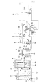
- FIG.1 and FIG.2 is a figure which shows schematic structure of the calendar equipment S of this embodiment
- FIG. 1 is a side view
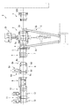
- FIG. 2 is a top view.
- the calendar facility S of the present embodiment is installed in a tire manufacturing factory, and manufactures a tire component (hereinafter referred to as a product sheet 100) in which a cord made of a plurality of metal wires is sandwiched between rubber sheets. It is equipment to do.
- the calendar equipment S of this embodiment includes a splice press device 1, a calendar device 2, a conveyor device 3, a load cell 4, a thickness measuring device 5, and an overtension bridal roller device. 6, a liner delivery device 7, a cooling device 8, a windup accumulator device 9, a centering device 10, a windup feed roller device 11, a winding device 12, and a cutter device 13.
- the splice press apparatus 1 connects the cords 200 supplied to the calendar facility S of the present embodiment.
- the splice press apparatus 1 connects the rear end of the cord 200 supplied earlier and the front end of the cord 200 supplied later by the supplied rubber.
- the calendar device 2 forms a product sheet 100 (sheet) by sticking rubber sheets on both sides of a cord 200.
- the calendar device 2 is disposed on the downstream side (the direction side in which the code 200 is sent) of the splice press device 1.
- the calendar device 2 includes four heating rollers 2a arranged in an S-shape, a motor 2b for driving the heating roller 2a, and the like from the upstream side (the side opposite to the direction in which the code 200 is sent).
- a product sheet 100 is formed by sticking a rubber sheet molded between the heating rollers 2 a to the supplied cord 200.
- the calendar device 2 sends the product sheet 100 obliquely upward.
- the calendar device 2 includes an adjustment mechanism (not shown) for adjusting the inclination and curvature of each heating roller 2a.
- the conveyor device 3 is a device that supplies rubber that has been kneaded and molded into a sheet shape to the calendar device 2, and supplies rubber between the heating rollers 2 a of the calendar device 2.
- the conveyor device 3 includes a wigwag conveyor device 3a whose tip on the supply side can be turned left and right to supply rubber uniformly between the heating rollers 2a, and rubber for the wigwag conveyor device 3a. And a feed conveyor device 3b for feeding.
- the load cell 4 is a sensor for detecting the tension applied to the product sheet 100 sent from the calendar device 2, and is arranged on the downstream side (the direction in which the product sheet 100 is sent) of the calendar device 2. And the load cell 4 sends out the product sheet 100 supplied from diagonally downward in a horizontal direction.
- the detection result of the load cell 4 is used as a control signal for controlling the rotation of the drive roller of the cooling device 8.
- the thickness measuring device 5 is a sensor for detecting the thickness of the product sheet 100 in the width direction, and is disposed on the downstream side of the load cell 4. The detection result of the thickness measuring device 5 is used as a control signal for controlling an adjusting mechanism for adjusting the inclination and curvature of each heating roller 2a of the calendar device 2.
- the over tension bridal roller device 6 is for suppressing damage to the product sheet 100 by releasing the support of the product sheet 100 when an abnormal tension is applied to the product sheet 100. 5 on the downstream side.
- the over tension bridal roller device 6 supports the product sheet 100 when normal tension is applied to the product sheet 100, and guides the product sheet 100 supplied from the horizontal direction downward. Function as.
- the liner delivery device 7 is disposed below the overtension bridal roller device 6, supports the roller around which the liner to be affixed to both surfaces of the product sheet 100 is wound, and delivers the liner while applying a brake. To do.
- a guide roller 14 is installed below the liner feeding device 7, and the product sheet 100 fed from above by the guide roller 14 is sent out in the horizontal direction.
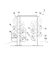
- the cooling device 8 cools the product sheet 100, and has a configuration in which two cooling roller units 8a and 8b are arranged in the conveying direction of the product sheet 100 as shown in the enlarged view of FIG. .
- Each of the cooling roller units 8a and 8b includes four cooling rollers 8c and a support member 8d that supports the cooling roller 8c.
- Each of the cooling rollers 8c has a surface cooled by supplying a refrigerant therein, and cools the product sheet 100 to be turned around. Further, the support member 8d is erected in the vertical direction. In each of the cooling roller units 8a and 8b, the cooling roller 8c is alternately supported on the left and right of the support member 8d and arranged in the vertical direction.
- the product sheet 100 is first passed around the cooling roller 8c installed at the lowermost position, and then sequentially passed around the upper cooling roller 8c. Then, the product sheet 100 is sent out in a substantially horizontal direction from the cooling roller 8c installed at the top. That is, the product sheet 100 is supplied from below in the cooling roller unit 8a disposed on the upstream side.
- the product sheet 100 is first wound around the cooling roller 8c installed at the uppermost position, and is sequentially wound around the lower cooling roller 8c. And the product sheet 100 is sent out in the substantially horizontal direction from the cooling roller 8c installed in the lowermost part. That is, the product sheet 100 is delivered from below in the cooling roller unit 8b disposed on the downstream side.
- the cooling roller unit 8a arranged on the upstream side is configured to be able to supply the product sheet 100 from below, and the cooling roller unit 8b arranged on the downstream side is arranged from below.
- the product sheet 100 can be sent out.
- cooling rollers 8c of the cooling roller unit 8a arranged on the downstream side three cooling rollers 8c including the most downstream cooling roller 8c function as drive rollers that are rotationally driven by a motor 8e (see FIG. 2).
- the height of the support member 8d provided in the cooling roller unit 8a disposed on the upstream side and the support member 8d provided on the cooling roller unit 8b disposed on the downstream side are set to be the same.
- the support member 8d of each cooling roller unit 8a, 8b has a height at which the cooling roller 8c can be disposed further above the four cooling rollers 8c that are already installed. Yes.
- the wind-up accumulator device 9 is for stopping the conveyance of the product sheet 100 on its downstream side without stopping the supply of the product sheet 100 from the cooling device 8, and is arranged on the downstream side of the cooling device 8. ing.
- the wind-up accumulator device 9 includes a plurality of rollers 9a around which the product sheet 100 is wound. A part of the rollers 9a is fixed to a carriage 9c fixed to the hydraulic cylinder 9b and can be moved up and down. In the wind-up accumulator device 9, the carriage 9 c is raised according to the supply speed of the product sheet 100 from the cooling device 8 and the space between the rollers 9 a is expanded to stop the conveyance of the downstream product sheet 100.
- the windup accumulator device 9 includes a guide roller 9d that sends the product sheet 100 upward.
- the centering device 10 corrects the positional deviation of the product sheet 100 in the width direction.
- the centering device 10 is disposed on the downstream side of the windup accumulator device 9 and is fixed to the frame of the windup accumulator device 9.
- the windup feed roller device 11 sets a tension applied to the product sheet 100 on the downstream side of the cooling device 8, and includes a drive roller 11a.
- the windup feed roller device 11 is installed on the downstream side of the centering device 10, and the product sheet 100 fed in a substantially horizontal direction by the guide roller 15 installed between the centering device 10 and the windup feed roller device 11. 11 is supplied.
- the windup feed roller device 11 sends the supplied product sheet 100 downward.
- the winding device 12 winds up the product sheet 100, and two winding devices 12 are arranged below the windup feed roller device 11. Then, the product sheet 100 delivered from the windup feed roller device 11 is wound by any of the winding devices 12.
- the cutter device 13 is installed between the windup feed roller device 11 and the winding device 12, and cuts the product sheet 100 at a timing when the winding amount of the product sheet 100 in the winding device 12 becomes a predetermined amount.
- the calendar facility S of the present embodiment includes a control device (not shown) and is controlled by a control device to which each device is electrically connected.
- the cord 200 is supplied to the calendar device 2 via the splice press device 1.
- the splice press device 1 connects the rear end of the cord 200 and the front end of the next cord 200 with rubber.
- the tension applied to the cord 200 is controlled by the rotational drive of the heating roller 2a of the calendar device 2.
- the product sheet 100 delivered from the calendar device 2 is supplied to the cooling device 8 via the load cell 4, the thickness measuring device 5, and the overtension bridal roller device 6.
- the tension applied to the product sheet 100 is detected by the load cell 4, and the rotation drive of the driving roller (cooling roller 8 c) of the cooling device 8 is controlled based on the detection result, whereby the calendar device 2 to the cooling device 8 are controlled. In the meantime, the tension applied to the product sheet 100 is kept constant.
- the thickness measuring device 5 detects the thickness of the product sheet 100 in the width direction, and based on the detection result, the inclination and curvature of the heating roller 2a of the calendar device 2 are adjusted so that the thickness of the product sheet 100 is uniform. Is done.
- the overtension bridal roller device 6 releases the support of the product sheet 100, thereby suppressing damage to the product sheet 100.
- the product sheet 100 passes through the vicinity of the liner delivery device 7 before being supplied to the cooling device 8, and the liner delivered from the liner delivery device 7 is attached to both sides.
- the product sheet 100 supplied to the cooling device 8 is cooled and discharged by the cooling rollers 8 c included in the respective cooling roller units 8 a and 8 b of the cooling device 8.
- the cooling device 8 has a configuration in which two cooling roller units 8 a and 8 b are arranged in the conveyance direction of the product sheet 100.
- the product sheet 100 is supplied to the cooling device 8 from below the cooling roller unit 8 a disposed on the upstream side. For this reason, the product sheet 100 is supplied to the cooling device 8 without being pulled up. Further, the product sheet 100 sent out from the cooling roller unit 8a arranged on the upstream side is supplied from above to the cooling roller unit 8b arranged on the downstream side and discharged from below.
- the product sheet 100 delivered from the cooling device 8 is supplied to the centering device 10 via the wind-up accumulator device 9 so that the positional deviation is corrected.
- the product sheet 100 is supplied to the winding device 12 via the wind-up feed roller device 11 and wound.
- the winding device 12 is switched, the product sheet 100 is cut by the cutter device 13, the rotational driving force of the windup feed roller device 11 is reduced, and the carriage 9c of the windup accumulator device 9 is raised. Thereby, the conveyance of the product sheet 100 on the downstream side of the windup accumulator device 9 is stopped.
- the rotation driving force of the windup feed roller device 11 is increased from the normal state and the product sheet 100 accumulated in the windup accumulator device 9 is sent out, and then the windup feed roller The rotational driving force of the device 11 is in a normal state.
- the cooling device 8 has a configuration in which a plurality of cooling roller units 8 a and 8 b including the cooling roller 8 c and the support member 8 d are arranged in the conveyance direction of the product sheet 100. Have.
- the cooling capacity required for the cooling device 8 is the same, approximately the same number of cooling rollers are required.
- the cooling roller 8c is distributed and arranged in the plurality of cooling roller units 8a and 8c, the conventional cooling roller units 8a and 8b have the same level of cooling capability.
- the cooling device can be lower.
- each cooling roller unit 8a, 8b is lower than that of a conventional cooling device, the work at a high place is reduced and the maintenance of the cooling device 8 is facilitated. Further, since the height of each cooling roller unit 8a, 8b is lower than that of the conventional cooling device, it is easy to increase the cooling capacity of the cooling device 8 by changing the specifications of the calendar facility S or the like. The cooling roller 8c can be added. Further, the height of each cooling roller unit 8a, 8b is lower than that of the conventional cooling device, so that the cooling device 8 can be easily transported and the cooling device 8 can be easily assembled.
- the installation position of the cooling device is the same, the longer the pulling distance of the product sheet 100 is, the closer the pulling angle of the product sheet 100 becomes vertical. For this reason, in a calendar facility equipped with a conventional cooling device, the production sheet 100 before being supplied to the cooling device is likely to come into contact with the cooling roller, and the production sheet 100 may be damaged.
- the calendar facility S of the present embodiment even when the product sheet 100 is supplied from above the cooling roller units 8a and 8b, the pulling angle of the product sheet is relaxed, and the manufacturing sheet 100 and the cooling sheet 100 are cooled. It becomes possible to suppress the contact of the roller 8c.
- the cooling roller unit 8a disposed on the upstream side is configured to be able to supply the product sheet 100 from below. For this reason, the pulling distance of the product sheet 100 supplied to the cooling device 8 can be almost eliminated, and the occurrence of sheet deformation and sheet position deviation can be suppressed more reliably.
- the cooling roller unit 8b disposed on the downstream side is configured to be able to discharge the product sheet 100 from below. For this reason, the cooling roller 8c functioning as a driving roller can be disposed at the lowest position, and maintenance of the motor 8e and the like can be easily performed.
- the structure provided with the two cooling roller units 8a and 8b whose cooling device 8 is an even number is employ
- the number of the cooling roller units 8a and 8b is an even number as described above, the product sheet 100 is supplied from the lower side to the most upstream cooling roller unit on the most upstream side, and the product sheet 100 is formed at the shortest distance between the cooling roller units. By performing the delivery, the product sheet 100 is discharged from below the most downstream cooling roller unit on the most downstream side. Therefore, when the number of the cooling roller units 8a and 8b is an even number, the product sheet 100 is supplied to the cooling device 8 from below without wasteful routing of the product sheet 100, and the product from the lower side of the cooling device 8 is supplied. The sheet 100 can be discharged.
- the cooling device 8 includes two cooling roller units 8a and 8b.
- the conventional calendar device requires a guide roller for pulling up the product sheet 100 above the cooling device in addition to a single cooling device. Therefore, the calendar facility S of the present embodiment can have almost the same line length as that of the conventional calendar device.
- the two cooling roller units 8a and 8b have substantially the same configuration except for a mechanism for driving the cooling roller 8c such as the motor 8e. For this reason, it becomes possible to manufacture the cooling roller units 8a and 8b with the same specifications, and it becomes possible to manufacture the cooling device 8 at low cost.
- the calendar facility S including a plurality of devices other than the calendar device 2 and the cooling device 8 has been described.
- the present invention is not limited to this, and the device configuration excluding the calendar device 2 and the cooling device 8 can be arbitrarily changed according to the specifications of the product sheet 100.
- the cooling device 8 includes the two cooling roller units 8a and 8b has been described.
- the present invention is not limited to this, and it is also possible to employ a configuration in which the cooling device 8 further includes a plurality of (even or odd) cooling roller units.
- each cooling roller unit 8a, 8b demonstrated the structure provided with the four cooling rollers 8c.
- the present invention is not limited to this, and it is possible to employ a configuration in which each of the cooling roller units 8a and 8b further includes a plurality or a small number of cooling rollers 8c.
- the calendar facility of the present invention it is possible to suppress the occurrence of sheet deformation and sheet position deviation during product sheet cooling.
- the calendar equipment of the present invention can easily change the specifications and maintain the cooling device, and can stably produce high-quality sheets.
Landscapes
- Engineering & Computer Science (AREA)
- Mechanical Engineering (AREA)
- Casting Or Compression Moulding Of Plastics Or The Like (AREA)
Abstract
シートの形成を行うカレンダ装置と、該カレンダ装置から排出された前記シートを冷却する冷却装置とを備えるカレンダ設備であって、前記冷却装置は、前記シートが廻し掛けられ、前記シートを冷却する冷却ローラと該冷却ローラを支持する支持部材とを備える冷却ローラユニットが前記シートの搬送方向に複数配置された構成を有することを特徴とするカレンダ設備。
Description
本発明は、シートの形成を行うカレンダ装置と、該カレンダ装置から排出された上記シートを冷却する冷却装置とを備えるカレンダ設備に関するものである。
本願は、2008年11月26日に、日本に出願された特願2008-301255号に基づき優先権を主張し、その内容をここに援用する。
本願は、2008年11月26日に、日本に出願された特願2008-301255号に基づき優先権を主張し、その内容をここに援用する。
従来から、所望の機能を有するシートを形成するカレンダ装置(特許文献1参照)や該カレンダ装置から排出されたシートを冷却する冷却装置を備えるカレンダ設備が、例えばタイヤ等の製造工場の一部において用いられている。
カレンダ設備が備える冷却装置は、複数の冷却ローラが上方に積み上げられて構成されており、各冷却ローラに順に廻し掛けられたシートを各冷却ローラで順次冷却することによってカレンダ装置から連続的に排出されるシートを連続的に冷却する。
冷却装置が備える冷却ローラの数は、カレンダ装置から排出されるシートの冷却温度に依存して決定される。つまり、加熱されたシートを冷却温度に冷却するために、同様の冷却能力を有する冷却ローラが何個必要であるかが決定される。
単一の冷却ローラの冷却能力は限られているため、時には冷却装置における冷却ローラの数が十数個に及ぶ場合もある。このため、冷却装置が非常に背丈の高い構造となる。
単一の冷却ローラの冷却能力は限られているため、時には冷却装置における冷却ローラの数が十数個に及ぶ場合もある。このため、冷却装置が非常に背丈の高い構造となる。
カレンダ設備では、冷却装置より下流側においてシートを搬送する駆動力を低減するために、複数の冷却ローラのうち、少なくとも最下流側の冷却ローラを駆動ローラとする必要がある。駆動ローラにはモータ等の駆動源が接続されるため、メンテナンスの行い易さ、及び冷却装置の重量バランスの観点から最下流側の冷却ローラは、冷却装置の下方に設置される。
つまり、従来の冷却装置は、背丈の高い構造を有すると共に、最下流側の冷却ローラが最下方に設置される構成を有している。このため、カレンダ装置から排出されたシートは、冷却装置に対して上方から供給される。
しかしながら、背丈の高い冷却装置の上方にシートを供給するためには、カレンダ装置から排出されたシートを長い距離上方に引き上げる必要が生じ、シートを引き上げている間にシートの変形やシートの位置ズレが生じ易くなる。
しかしながら、背丈の高い冷却装置の上方にシートを供給するためには、カレンダ装置から排出されたシートを長い距離上方に引き上げる必要が生じ、シートを引き上げている間にシートの変形やシートの位置ズレが生じ易くなる。
本発明は、上述する問題点に鑑みてなされたもので、カレンダ設備において、冷却装置に供給する際のシートの引き上げ距離を短くする、あるいは引き上げ距離を無くすことによって、シート変形やシート位置ズレの発生を抑制することを目的とする。
本発明は、上記課題を解決するための手段として、以下の構成を採用する。
本発明の第1の態様は、シートの形成を行うカレンダ装置と、該カレンダ装置から排出された上記シートを冷却する冷却装置とを備えるカレンダ設備であって、上記冷却装置は、廻し掛けられた上記シートを冷却する冷却ローラと該冷却ローラを支持する支持部材とを備える冷却ローラユニットが上記シートの搬送方向に複数配置された構成を有するカレンダ設備である。
本発明の第2の態様は、上記第1の態様にかかるカレンダ設備であって、上記冷却ローラユニットが、鉛直方向に立設される上記支持部材と、該支持部材に支持されて鉛直方向に配列される複数の上記冷却ローラとを備えるカレンダ設備である。
本発明の第3の態様は、上記第1または第2の態様にかかるカレンダ設備であって、上記シートの搬送方向における最も上流側の冷却ローラユニットが下方から上記シートを供給可能に構成され、上記シートの搬送方向における最も下流側の冷却ローラユニットが下方から上記シートを排出可能に構成されているカレンダ設備である。
本発明の第4の態様は、上記第1乃至第3いずれかの態様にかかるカレンダ設備であって、上記冷却装置が、上記冷却ローラユニットが上記シートの搬送方向に偶数個配置された構成を有するカレンダ設備である。
本発明の第5の態様は、上記第1乃至第4いずれかの態様にかかるカレンダ設備であって、上記冷却装置が、上記冷却ローラユニットが上記シートの搬送方向に2つ配置された構成を有するカレンダ設備である。
本発明によれば、カレンダ設備の冷却装置は、冷却ローラと支持部材とを備える冷却ローラユニットがシートの搬送方向に複数配置された構成を有する。
このため、冷却装置に求められる所定の冷却能力に対応する個数の冷却ローラが、複数の冷却ローラユニットに分散して配置される。そのため、本発明の冷却装置は、同一の冷却能力を有する従来の冷却装置と比較して、背丈が低い冷却ユニットから構成される。
したがって、本発明によれば、冷却ローラユニットの上方からシートを供給する場合であっても、従来の冷却装置の上方からシートを供給する場合と比較して、シートを引き上げる距離が短くなり、シート変形やシート位置ズレの発生を抑制することが可能となる。
このため、冷却装置に求められる所定の冷却能力に対応する個数の冷却ローラが、複数の冷却ローラユニットに分散して配置される。そのため、本発明の冷却装置は、同一の冷却能力を有する従来の冷却装置と比較して、背丈が低い冷却ユニットから構成される。
したがって、本発明によれば、冷却ローラユニットの上方からシートを供給する場合であっても、従来の冷却装置の上方からシートを供給する場合と比較して、シートを引き上げる距離が短くなり、シート変形やシート位置ズレの発生を抑制することが可能となる。
以下、図面を参照して、本発明に係るカレンダ設備の一実施形態について説明する。なお、以下の図面において、各部材を認識可能な大きさとするために、各部材の縮尺を適宜変更している。
図1及び図2は、本実施形態のカレンダ設備Sの概略構成を示す図であり、図1が側面図であり、図2が平面図である。
本実施形態のカレンダ設備Sは、タイヤの製造工場に設置されるものであり、複数の金属ワイヤからなるコードがゴムシートによって挟み込まれたタイヤの構成部品(以下、製品シート100と称する)を製造するための設備である。
図1及び図2に示すように、本実施形態のカレンダ設備Sは、スプライスプレス装置1と、カレンダ装置2と、コンベア装置3と、ロードセル4と、厚み計測装置5と、オーバテンションブライダルローラ装置6と、ライナ送出装置7と、冷却装置8と、ワインドアップアキュムレータ装置9と、センタリング装置10と、ワインドアップフィードローラ装置11と、巻取装置12と、カッタ装置13とを備えている。
本実施形態のカレンダ設備Sは、タイヤの製造工場に設置されるものであり、複数の金属ワイヤからなるコードがゴムシートによって挟み込まれたタイヤの構成部品(以下、製品シート100と称する)を製造するための設備である。
図1及び図2に示すように、本実施形態のカレンダ設備Sは、スプライスプレス装置1と、カレンダ装置2と、コンベア装置3と、ロードセル4と、厚み計測装置5と、オーバテンションブライダルローラ装置6と、ライナ送出装置7と、冷却装置8と、ワインドアップアキュムレータ装置9と、センタリング装置10と、ワインドアップフィードローラ装置11と、巻取装置12と、カッタ装置13とを備えている。
スプライスプレス装置1は、本実施形態のカレンダ設備Sに供給される上記コード200同士を接続するものである。スプライスプレス装置1は、先に供給されたコード200の後端と後に供給されるコード200の先端とを、供給されるゴムによって接続する。
カレンダ装置2は、コード200の両面に対してゴムシートを貼り付けることによって製品シート100(シート)を形成するものである。カレンダ装置2は、スプライスプレス装置1の下流側(コード200が送出される方向側)に配置されている。
このカレンダ装置2は、S字状に配列される4つの加熱ローラ2aと、該加熱ローラ2aを駆動するモータ2b等を備えており、上流側(コード200が送出される方向と反対側)から供給されるコード200に、加熱ローラ2a間で成型したゴムシートを貼り付けることによって製品シート100を形成する。カレンダ装置2は、製品シート100を斜め上方に向けて送出する。
なお、カレンダ装置2は、各加熱ローラ2aの傾きや湾曲を調節するための調節機構(図示せず)を備えている。
このカレンダ装置2は、S字状に配列される4つの加熱ローラ2aと、該加熱ローラ2aを駆動するモータ2b等を備えており、上流側(コード200が送出される方向と反対側)から供給されるコード200に、加熱ローラ2a間で成型したゴムシートを貼り付けることによって製品シート100を形成する。カレンダ装置2は、製品シート100を斜め上方に向けて送出する。
なお、カレンダ装置2は、各加熱ローラ2aの傾きや湾曲を調節するための調節機構(図示せず)を備えている。
コンベア装置3は、混練された後にシート状に成型されたゴムをカレンダ装置2に供給する装置であり、カレンダ装置2の加熱ローラ2a間にゴムを供給する。
なお、コンベア装置3は、加熱ローラ2a間に均等にゴムを供給するために供給する側の先端が左右に回動可能とされたウィグワグコンベア装置3aと、該ウィグワグコンベア装置3aにゴムを供給するためのフィードコンベア装置3bとを備えている。
なお、コンベア装置3は、加熱ローラ2a間に均等にゴムを供給するために供給する側の先端が左右に回動可能とされたウィグワグコンベア装置3aと、該ウィグワグコンベア装置3aにゴムを供給するためのフィードコンベア装置3bとを備えている。
ロードセル4は、カレンダ装置2から送出された製品シート100に掛かる張力を検出するためのセンサであり、カレンダ装置2の下流側(製品シート100の送出される方向側)に配置されている。そして、ロードセル4は、斜め下方から供給される製品シート100を水平方向に送出する。
なお、ロードセル4の検出結果は、冷却装置8の駆動ローラの回転を制御する制御信号として用いられる。
なお、ロードセル4の検出結果は、冷却装置8の駆動ローラの回転を制御する制御信号として用いられる。
厚み計測装置5は、製品シート100の幅方向の厚みを検出するためのセンサであり、ロードセル4の下流側に配置されている。
なお、厚み計測装置5の検出結果は、カレンダ装置2の各加熱ローラ2aの傾きや湾曲を調節するための調節機構を制御する制御信号として用いられる。
なお、厚み計測装置5の検出結果は、カレンダ装置2の各加熱ローラ2aの傾きや湾曲を調節するための調節機構を制御する制御信号として用いられる。
オーバテンションブライダルローラ装置6は、製品シート100に対して異常な張力が掛かった場合に製品シート100の支持を解除することによって製品シート100への損傷を抑制するためのものであり、厚み計測装置5の下流側に配置されている。
なお、オーバテンションブライダルローラ装置6は、製品シート100に対して正常な張力が掛かっている場合には、製品シート100を支持し、水平方向から供給された製品シート100を下方に送出するガイドローラとして機能する。
なお、オーバテンションブライダルローラ装置6は、製品シート100に対して正常な張力が掛かっている場合には、製品シート100を支持し、水平方向から供給された製品シート100を下方に送出するガイドローラとして機能する。
ライナ送出装置7は、オーバテンションブライダルローラ装置6の下方に配置されており、製品シート100の両面に貼付されるライナが巻回されたローラを軸支すると共に、ブレーキを利かせながらライナを送出するものである。
なお、ライナ送出装置7の下方には、ガイドローラ14が設置されており、当該ガイドローラ14によって上方から供給される製品シート100が水平方向に送出される。
なお、ライナ送出装置7の下方には、ガイドローラ14が設置されており、当該ガイドローラ14によって上方から供給される製品シート100が水平方向に送出される。
冷却装置8は、製品シート100を冷却するものであり、図3の拡大図に示すように、2つの冷却ローラユニット8a,8bが製品シート100の搬送方向に配置された構成を有している。
各冷却ローラユニット8a,8bは、4つの冷却ローラ8cと、該冷却ローラ8cを支持する支持部材8dとを備えている。
各冷却ローラ8cは、内部に冷媒が供給されることによって表面が冷却されており、廻し掛けられる製品シート100を冷却するものである。また、支持部材8dは、鉛直方向に立設されている。
そして、各冷却ローラユニット8a,8bにおいて、冷却ローラ8cは、支持部材8dの左右に交互に支持されて鉛直方向に配列されている。
各冷却ローラ8cは、内部に冷媒が供給されることによって表面が冷却されており、廻し掛けられる製品シート100を冷却するものである。また、支持部材8dは、鉛直方向に立設されている。
そして、各冷却ローラユニット8a,8bにおいて、冷却ローラ8cは、支持部材8dの左右に交互に支持されて鉛直方向に配列されている。
上流側に配置された冷却ローラユニット8aでは、製品シート100は、まず最下方に設置された冷却ローラ8cに廻しかけられ、順次上方の冷却ローラ8cに廻し掛けられる。そして、製品シート100は、最上方に設置された冷却ローラ8cから略水平方向に送出される。
つまり、上流側に配置された冷却ローラユニット8aにおいては、下方から製品シート100が供給される。
つまり、上流側に配置された冷却ローラユニット8aにおいては、下方から製品シート100が供給される。
一方、下流側に配置された冷却ローラユニット8bでは、製品シート100は、まず最上方に設置された冷却ローラ8cに廻し掛けられ、順次下方の冷却ローラ8cに廻し掛けられる。そして、製品シート100は、最下方に設置された冷却ローラ8cから略水平方向に送出される。
つまり、下流側に配置された冷却ローラユニット8bにおいては、下方から製品シート100が送出される。
つまり、下流側に配置された冷却ローラユニット8bにおいては、下方から製品シート100が送出される。
このように、本実施形態のカレンダ設備Sにおいては、上流側に配置された冷却ローラユニット8aが下方から製品シート100を供給可能に構成され、下流側に配置された冷却ローラユニット8bが下方から製品シート100を送出可能に構成されている。
下流側に配置された冷却ローラユニット8aの冷却ローラ8cのうち、最下流の冷却ローラ8cを含む3つの冷却ローラ8cが、モータ8e(図2参照)によって回転駆動される駆動ローラとして機能する。
本実施形態のカレンダ設備Sにおいては、上流側に配置された冷却ローラユニット8aが備える支持部材8dと、下流側に配置された冷却ローラユニット8bが備える支持部材8dとの高さが同じに設定されている。
また、各冷却ローラユニット8a,8bの支持部材8dは、図3に示すように、既に設置されている4つの冷却ローラ8cよりもさらに上方に冷却ローラ8cを配置可能な高さを有している。
また、各冷却ローラユニット8a,8bの支持部材8dは、図3に示すように、既に設置されている4つの冷却ローラ8cよりもさらに上方に冷却ローラ8cを配置可能な高さを有している。
ワインドアップアキュムレータ装置9は、冷却装置8からの製品シート100の供給を止めることなく、自らの下流側の製品シート100の搬送を停止するためのものであり、冷却装置8の下流側に配置されている。
このワインドアップアキュムレータ装置9は、製品シート100が廻し掛けられる複数のローラ9aを備えている。そして、一部のローラ9aは、油圧シリンダ9bに固定されたキャリッジ9cに固定されており昇降可能とされている。
このワインドアップアキュムレータ装置9においては、冷却装置8からの製品シート100の供給速度に応じて、キャリッジ9cが上昇されてローラ9a間が拡がることによって下流側の製品シート100の搬送が停止される。
なお、ワインドアップアキュムレータ装置9は、製品シート100を上方に送出するガイドローラ9dを備えている。
このワインドアップアキュムレータ装置9は、製品シート100が廻し掛けられる複数のローラ9aを備えている。そして、一部のローラ9aは、油圧シリンダ9bに固定されたキャリッジ9cに固定されており昇降可能とされている。
このワインドアップアキュムレータ装置9においては、冷却装置8からの製品シート100の供給速度に応じて、キャリッジ9cが上昇されてローラ9a間が拡がることによって下流側の製品シート100の搬送が停止される。
なお、ワインドアップアキュムレータ装置9は、製品シート100を上方に送出するガイドローラ9dを備えている。
センタリング装置10は、製品シート100の幅方向の位置ズレを修正するものである。センタリング装置10は、ワインドアップキュムレータ装置9の下流側に配置されており、ワインドアップアキュムレータ装置9のフレームに対して固定されている。
ワインドアップフィードローラ装置11は、冷却装置8より下流側における製品シート100に掛かる張力を設定するものであり、駆動ローラ11aを備えている。
ワインドアップフィードローラ装置11は、センタリング装置10の下流側に設置されており、センタリング装置10との間に設置されたガイドローラ15によって略水平方向に送出された製品シート100がワインドアップフィードローラ装置11に供給される。ワインドアップフィードローラ装置11は、この供給された製品シート100を下方に送出する。
ワインドアップフィードローラ装置11は、センタリング装置10の下流側に設置されており、センタリング装置10との間に設置されたガイドローラ15によって略水平方向に送出された製品シート100がワインドアップフィードローラ装置11に供給される。ワインドアップフィードローラ装置11は、この供給された製品シート100を下方に送出する。
巻取装置12は、製品シート100を巻き取るものであり、ワインドアップフィードローラ装置11の下方に2つ配置されている。
そして、いずれかの巻取装置12によってワインドアップフィードローラ装置11から送出される製品シート100が巻き取られる。
そして、いずれかの巻取装置12によってワインドアップフィードローラ装置11から送出される製品シート100が巻き取られる。
カッタ装置13は、ワインドアップフィードローラ装置11と巻取装置12との間に設置され、巻取装置12における製品シート100の巻回量が所定量となるタイミングで製品シート100を切断する。
また、本実施形態のカレンダ設備Sは、不図示の制御装置を備えており、各装置が電気的に接続される制御装置によって制御されている。
次に、このように構成された本実施形態のカレンダ設備Sにおいて製品シート100を巻取装置12にて巻き取るまでの動作について説明する。
なお、以下に記載する動作は、特に断りがない限り、制御装置によって制御される。
なお、以下に記載する動作は、特に断りがない限り、制御装置によって制御される。
まず、外部よりコード200が本実施形態のカレンダ設備Sに供給されると、コード200は、スプライスプレス装置1を介してカレンダ装置2に供給される。
ここで、コード200の後端がスプライスプレス装置1を通過する際には、スプライスプレス装置1によって、コード200の後端と次のコード200の先端とがゴムによって接続される。
コード200に掛かる張力は、カレンダ装置2の加熱ローラ2aの回転駆動によって制御されている。
ここで、コード200の後端がスプライスプレス装置1を通過する際には、スプライスプレス装置1によって、コード200の後端と次のコード200の先端とがゴムによって接続される。
コード200に掛かる張力は、カレンダ装置2の加熱ローラ2aの回転駆動によって制御されている。
一方で、コンベア装置3によって混練された後にシート状に成型されたゴムがカレンダ装置2に供給される。
カレンダ装置2に供給されたコード200の両面に、加熱ローラ2aによって形成されたゴムシートが貼付されることによって、製品シート100が形成される。
カレンダ装置2に供給されたコード200の両面に、加熱ローラ2aによって形成されたゴムシートが貼付されることによって、製品シート100が形成される。
カレンダ装置2から送出された製品シート100は、ロードセル4、厚み計測装置5、オーバテンションブライダルローラ装置6を介して冷却装置8に供給される。
ロードセル4によって製品シート100に掛かっている張力が検出され、当該検出結果に基づいて冷却装置8の駆動ローラ(冷却ローラ8c)の回転駆動が制御されることによってカレンダ装置2から冷却装置8までの間に製品シート100に掛かる張力が一定に保たれる。
厚み計測装置5によって、製品シート100の幅方向の厚みが検出され、当該検出結果に基づいて、製品シート100の厚みが均一化されるようにカレンダ装置2の加熱ローラ2aの傾き及び湾曲が調節される。
製品シート100に掛かる張力が異常に増加した場合には、オーバテンションブライダルローラ装置6が製品シート100の支持を解除することによって製品シート100への損傷が抑制される。
製品シート100は、冷却装置8に供給される前にライナ送出装置7の近傍を通過し、ライナ送出装置7から送出されるライナが両面に貼付される。
ロードセル4によって製品シート100に掛かっている張力が検出され、当該検出結果に基づいて冷却装置8の駆動ローラ(冷却ローラ8c)の回転駆動が制御されることによってカレンダ装置2から冷却装置8までの間に製品シート100に掛かる張力が一定に保たれる。
厚み計測装置5によって、製品シート100の幅方向の厚みが検出され、当該検出結果に基づいて、製品シート100の厚みが均一化されるようにカレンダ装置2の加熱ローラ2aの傾き及び湾曲が調節される。
製品シート100に掛かる張力が異常に増加した場合には、オーバテンションブライダルローラ装置6が製品シート100の支持を解除することによって製品シート100への損傷が抑制される。
製品シート100は、冷却装置8に供給される前にライナ送出装置7の近傍を通過し、ライナ送出装置7から送出されるライナが両面に貼付される。
冷却装置8に供給された製品シート100は、冷却装置8の各冷却ローラユニット8a,8bが備える冷却ローラ8cによって冷却されて排出される。
ここで、本実施形態のカレンダ設備Sにおいては、冷却装置8は、2つの冷却ローラユニット8a,8bが製品シート100の搬送方向に配置された構成を有している。冷却装置8には、上流側に配置された冷却ローラユニット8aの下方から製品シート100が供給される。このため、製品シート100が引き上げられることなく冷却装置8に供給される。
また、上流側に配置された冷却ローラユニット8aから送出された製品シート100は、下流側に配置された冷却ローラユニット8bに上方から供給されて下方から排出される。
ここで、本実施形態のカレンダ設備Sにおいては、冷却装置8は、2つの冷却ローラユニット8a,8bが製品シート100の搬送方向に配置された構成を有している。冷却装置8には、上流側に配置された冷却ローラユニット8aの下方から製品シート100が供給される。このため、製品シート100が引き上げられることなく冷却装置8に供給される。
また、上流側に配置された冷却ローラユニット8aから送出された製品シート100は、下流側に配置された冷却ローラユニット8bに上方から供給されて下方から排出される。
冷却装置8から送出された製品シート100は、ワインドアップアキュムレータ装置9を介してセンタリング装置10に供給されることによって位置ズレを修正される。
製品シート100は、ワインドアップフィードローラ装置11を介して巻取装置12に供給されて巻回される。
巻取装置12を切り替える際には、カッタ装置13によって製品シート100が切断されると共に、ワインドアップフィードローラ装置11の回転駆動力が低減され、ワインドアップアキュムレータ装置9のキャリッジ9cが上昇される。これによって、ワインドアップアキュムレータ装置9より下流側の製品シート100の搬送が停止される。巻取装置12の切り替えが完了した後は、ワインドアップフィードローラ装置11の回転駆動力が通常状態よりも増加されてワインドアップアキュムレータ装置9に溜まった製品シート100を送出し、その後ワインドアップフィードローラ装置11の回転駆動力が通常状態となる。
製品シート100は、ワインドアップフィードローラ装置11を介して巻取装置12に供給されて巻回される。
巻取装置12を切り替える際には、カッタ装置13によって製品シート100が切断されると共に、ワインドアップフィードローラ装置11の回転駆動力が低減され、ワインドアップアキュムレータ装置9のキャリッジ9cが上昇される。これによって、ワインドアップアキュムレータ装置9より下流側の製品シート100の搬送が停止される。巻取装置12の切り替えが完了した後は、ワインドアップフィードローラ装置11の回転駆動力が通常状態よりも増加されてワインドアップアキュムレータ装置9に溜まった製品シート100を送出し、その後ワインドアップフィードローラ装置11の回転駆動力が通常状態となる。
以上のような本実施形態のカレンダ設備Sによれば、冷却装置8は、冷却ローラ8cと支持部材8dとを備える冷却ローラユニット8a,8bが製品シート100の搬送方向に複数配置された構成を有する。
冷却装置8に求められる冷却能力が同じ場合、ほぼ同数の冷却ローラが必要となる。本実施形態の冷却装置8では、冷却ローラ8cが複数の冷却ローラユニット8a,8cに分散して配置されるため、各冷却ローラユニット8a,8bの高さを、同程度の冷却能力を有する従来の冷却装置よりも低くすることができる。
したがって、本実施形態のカレンダ設備Sによれば、冷却ローラユニット8a,8bの上方から製品シート100を供給する場合であっても、従来型の冷却装置の上方から製品シートを供給する場合と比較して、製品シート100を引き上げる距離が短くなり、シート変形やシート位置ズレの発生を抑制することが可能となる。
冷却装置8に求められる冷却能力が同じ場合、ほぼ同数の冷却ローラが必要となる。本実施形態の冷却装置8では、冷却ローラ8cが複数の冷却ローラユニット8a,8cに分散して配置されるため、各冷却ローラユニット8a,8bの高さを、同程度の冷却能力を有する従来の冷却装置よりも低くすることができる。
したがって、本実施形態のカレンダ設備Sによれば、冷却ローラユニット8a,8bの上方から製品シート100を供給する場合であっても、従来型の冷却装置の上方から製品シートを供給する場合と比較して、製品シート100を引き上げる距離が短くなり、シート変形やシート位置ズレの発生を抑制することが可能となる。
また、各冷却ローラユニット8a,8bの高さが従来の冷却装置と比較して低くなることによって、高所での作業が減少して冷却装置8のメンテナンスが容易となる。
また、各冷却ローラユニット8a,8bの高さが従来の冷却装置と比較して低いため、カレンダ設備Sの仕様変更等によって冷却装置8の冷却能力の増強が必要となった場合に、容易に冷却ローラ8cの増設が可能となる。
さらに、各冷却ローラユニット8a,8bの背丈が従来の冷却装置と比較して低くなることによって、冷却装置8の搬送が容易となり、冷却装置8の組立てが容易となる。
また、各冷却ローラユニット8a,8bの高さが従来の冷却装置と比較して低いため、カレンダ設備Sの仕様変更等によって冷却装置8の冷却能力の増強が必要となった場合に、容易に冷却ローラ8cの増設が可能となる。
さらに、各冷却ローラユニット8a,8bの背丈が従来の冷却装置と比較して低くなることによって、冷却装置8の搬送が容易となり、冷却装置8の組立てが容易となる。
冷却装置の設置位置が同一であるならば、製品シート100の引き上げ距離が長ければ長い程、製品シート100の引き上げ角度は垂直に近づく。そのため、従来型の冷却装置を備えるカレンダ設備では、冷却装置に供給される以前の製造シート100が冷却ローラに接触しやすくなり、製造シート100の損傷を招く可能性がある。
これに対して本実施形態のカレンダ設備Sによれば、冷却ローラユニット8a,8bの上方から製品シート100を供給する場合であっても、製品シートの引き上げ角度が緩和され、製造シート100と冷却ローラ8cの接触を抑制することが可能となる。
これに対して本実施形態のカレンダ設備Sによれば、冷却ローラユニット8a,8bの上方から製品シート100を供給する場合であっても、製品シートの引き上げ角度が緩和され、製造シート100と冷却ローラ8cの接触を抑制することが可能となる。
さらに、本実施形態のカレンダ設備Sによれば、上流側に配置される冷却ローラユニット8aが下方から製品シート100を供給可能に構成されている。このため、冷却装置8に供給される製品シート100の引き上げ距離を殆ど無くすことができ、より確実にシート変形やシート位置ズレの発生を抑制することが可能となる。
本実施形態のカレンダ設備Sによれば、下流側に配置される冷却ローラユニット8bが下方から製品シート100を排出可能に構成されている。このため、駆動ローラとして機能する冷却ローラ8cを最下方に配置することが可能となり、モータ8e等のメンテナンスを容易に行うことが可能となる。
本実施形態のカレンダ設備Sによれば、下流側に配置される冷却ローラユニット8bが下方から製品シート100を排出可能に構成されている。このため、駆動ローラとして機能する冷却ローラ8cを最下方に配置することが可能となり、モータ8e等のメンテナンスを容易に行うことが可能となる。
本実施形態のカレンダ設備Sにおいては、冷却装置8が偶数個である2つの冷却ローラユニット8a,8bを備える構成を採用している。
このように冷却ローラユニット8a,8bが偶数個である場合には、最も上流側の最上流冷却ローラユニットに下方から製品シート100を供給し、各冷却ローラユニット間において最短距離で製品シート100の受け渡しを行うことによって、最も下流側の最下流冷却ローラユニットの下方から製品シート100が排出される。
よって、冷却ローラユニット8a,8bが偶数個である場合には、製品シート100の無駄な引き廻しを行うことなく、冷却装置8に下方から製品シート100を供給し、冷却装置8の下方から製品シート100を排出することができる。
このように冷却ローラユニット8a,8bが偶数個である場合には、最も上流側の最上流冷却ローラユニットに下方から製品シート100を供給し、各冷却ローラユニット間において最短距離で製品シート100の受け渡しを行うことによって、最も下流側の最下流冷却ローラユニットの下方から製品シート100が排出される。
よって、冷却ローラユニット8a,8bが偶数個である場合には、製品シート100の無駄な引き廻しを行うことなく、冷却装置8に下方から製品シート100を供給し、冷却装置8の下方から製品シート100を排出することができる。
また、本実施形態のカレンダ設備Sの構成においては、冷却装置8が2つの冷却ローラユニット8a,8bを備える。
従来のカレンダ装置では、単一の冷却装置に加えて冷却装置の上方に製品シート100を引き上げるためのガイドローラを必要とする。従って、本実施形態のカレンダ設備Sは、従来のカレンダ装置とほぼ同一のライン長とすることができる。
従来のカレンダ装置では、単一の冷却装置に加えて冷却装置の上方に製品シート100を引き上げるためのガイドローラを必要とする。従って、本実施形態のカレンダ設備Sは、従来のカレンダ装置とほぼ同一のライン長とすることができる。
本実施形態のカレンダ設備Sにおいては、モータ8e等の冷却ローラ8cを駆動する機構を除いて、2つの冷却ローラユニット8a,8bがほぼ同一の構成を有している。このため、同様の仕様にて冷却ローラユニット8a,8bを製造することが可能となり、低コストで冷却装置8を製造することが可能となる。
以上、図面を参照しながら本発明の好適な実施形態について説明したが、本発明は上記実施形態に限定されるものではない。上述した実施形態において示した各構成部材の諸形状や組み合わせ等は一例であって、本発明の主旨から逸脱しない範囲において設計要求等に基づき種々変更可能である。
例えば、上記実施形態においては、カレンダ装置2及び冷却装置8以外に複数の装置を備えるカレンダ設備Sについて説明した。
しかしながら、本発明はこれに限定されるものではなく、カレンダ装置2及び冷却装置8を除く装置構成については、製品シート100の仕様に応じて任意に変更可能である。
しかしながら、本発明はこれに限定されるものではなく、カレンダ装置2及び冷却装置8を除く装置構成については、製品シート100の仕様に応じて任意に変更可能である。
また、上記実施形態においては、冷却装置8が2つの冷却ローラユニット8a,8bを備える構成について説明した。
しかしながら、本発明はこれに限定されるものではなく、冷却装置8がさらに複数(偶数、奇数を問わず)の冷却ローラユニットを備える構成を採用することも可能である。
しかしながら、本発明はこれに限定されるものではなく、冷却装置8がさらに複数(偶数、奇数を問わず)の冷却ローラユニットを備える構成を採用することも可能である。
また、上記実施形態においては、各冷却ローラユニット8a,8bが4つの冷却ローラ8cを備える構成について説明した。
しかしながら、本発明はこれに限定されるものではなく、各冷却ローラユニット8a,8bがさらに複数あるいは少数の冷却ローラ8cを備える構成を採用することも可能である。
しかしながら、本発明はこれに限定されるものではなく、各冷却ローラユニット8a,8bがさらに複数あるいは少数の冷却ローラ8cを備える構成を採用することも可能である。
本発明のカレンダ設備によれば、製品シート冷却時における、シート変形やシート位置ズレの発生を抑制することができる。また本発明のカレンダ設備は、冷却装置の仕様変更やメンテナンスが容易であり、高品質のシートを安定して生産することができる。
Claims (7)
- シートの形成を行うカレンダ装置と、該カレンダ装置から排出された前記シートを冷却する冷却装置とを備えるカレンダ設備であって、
前記冷却装置は、廻し掛けられた前記シートを冷却する冷却ローラと該冷却ローラを支持する支持部材とを備える冷却ローラユニットが前記シートの搬送方向に複数配置された構成を有することを特徴とするカレンダ設備。 - 前記冷却ローラユニットは、鉛直方向に立設される前記支持部材と、該支持部材に支持されて鉛直方向に配列される複数の前記冷却ローラとを備えることを特徴とする請求項1記載のカレンダ装置。
- 前記シートの搬送方向における最も上流側の冷却ローラユニットが下方から前記シートを供給可能に構成され、
前記シートの搬送方向における最も下流側の冷却ローラユニットが下方から前記シートを排出可能に構成されている
ことを特徴とする請求項1または2記載のカレンダ設備。 - 前記冷却装置は、前記冷却ローラユニットが前記シートの搬送方向に偶数個配置された構成を有することを特徴とする請求項1または2記載のカレンダ設備。
- 前記冷却装置は、前記冷却ローラユニットが前記シートの搬送方向に偶数個配置された構成を有することを特徴とする請求項3記載のカレンダ設備。
- 前記冷却装置は、前記冷却ローラユニットが前記シートの搬送方向に2つ配置された構成を有することを特徴とする請求項1または2記載のカレンダ設備。
- 前記冷却装置は、前記冷却ローラユニットが前記シートの搬送方向に2つ配置された構成を有することを特徴とする請求項3記載のカレンダ設備。
Applications Claiming Priority (2)
| Application Number | Priority Date | Filing Date | Title |
|---|---|---|---|
| JP2008-301255 | 2008-11-26 | ||
| JP2008301255A JP5412094B2 (ja) | 2008-11-26 | 2008-11-26 | カレンダ設備 |
Publications (1)
| Publication Number | Publication Date |
|---|---|
| WO2010061606A1 true WO2010061606A1 (ja) | 2010-06-03 |
Family
ID=42225492
Family Applications (1)
| Application Number | Title | Priority Date | Filing Date |
|---|---|---|---|
| PCT/JP2009/006389 Ceased WO2010061606A1 (ja) | 2008-11-26 | 2009-11-26 | カレンダ設備 |
Country Status (2)
| Country | Link |
|---|---|
| JP (1) | JP5412094B2 (ja) |
| WO (1) | WO2010061606A1 (ja) |
Families Citing this family (1)
| Publication number | Priority date | Publication date | Assignee | Title |
|---|---|---|---|---|
| CN103707531B (zh) * | 2012-10-02 | 2018-01-12 | 住友橡胶工业株式会社 | 橡胶条带的制造装置、制造方法、粘贴装置以及粘贴方法 |
Citations (2)
| Publication number | Priority date | Publication date | Assignee | Title |
|---|---|---|---|---|
| JPH08267484A (ja) * | 1995-03-28 | 1996-10-15 | Sekisui Chem Co Ltd | 繊維複合シートの製造方法 |
| JPH11114983A (ja) * | 1997-10-16 | 1999-04-27 | Ishikawajima Harima Heavy Ind Co Ltd | カレンダーのシート冷却装置 |
-
2008
- 2008-11-26 JP JP2008301255A patent/JP5412094B2/ja not_active Expired - Fee Related
-
2009
- 2009-11-26 WO PCT/JP2009/006389 patent/WO2010061606A1/ja not_active Ceased
Patent Citations (2)
| Publication number | Priority date | Publication date | Assignee | Title |
|---|---|---|---|---|
| JPH08267484A (ja) * | 1995-03-28 | 1996-10-15 | Sekisui Chem Co Ltd | 繊維複合シートの製造方法 |
| JPH11114983A (ja) * | 1997-10-16 | 1999-04-27 | Ishikawajima Harima Heavy Ind Co Ltd | カレンダーのシート冷却装置 |
Also Published As
| Publication number | Publication date |
|---|---|
| JP5412094B2 (ja) | 2014-02-12 |
| JP2010125656A (ja) | 2010-06-10 |
Similar Documents
| Publication | Publication Date | Title |
|---|---|---|
| JP5249596B2 (ja) | ゴムストリップ搬送装置 | |
| JP5618488B2 (ja) | カレンダ設備 | |
| CN105720293B (zh) | 卷绕装置和卷绕装置的设计方法 | |
| CN107310177A (zh) | 贴胶片材的形成方法以及装置 | |
| KR20090007145U (ko) | 컨베이어장치 | |
| JP5412094B2 (ja) | カレンダ設備 | |
| JP5422850B2 (ja) | アキューム装置 | |
| KR101243055B1 (ko) | 2브라이들 텐션레벨러시스템 | |
| CN213445485U (zh) | 一种卷式物料检修系统 | |
| US11505413B2 (en) | Vertical strip accumulator | |
| KR101713093B1 (ko) | 코어의 적층 높이 제어장치 | |
| CN219832725U (zh) | 一种卷绕设备 | |
| CN210236097U (zh) | 一种下板机的收料辅助装置 | |
| CN109263108B (zh) | 供料装置 | |
| CN221821430U (zh) | 一种应用于碳纤维材料的收放卷传输蓄料单元 | |
| JP2014159105A (ja) | タイヤ部材供給装置 | |
| US6688508B2 (en) | Conveyor device | |
| JP4696309B2 (ja) | 縦型ルーパー及びその運転方法 | |
| CN223316059U (zh) | 一种储料架 | |
| JP2013022875A (ja) | タイヤ部材供給装置 | |
| CN223547420U (zh) | 一种用于片材生产的储料装置及片材生产线 | |
| KR101810009B1 (ko) | 교정압연기를 구비한 필름 권취기 | |
| CN121650238B (zh) | 一种铝材生产覆膜装置 | |
| JP6087637B2 (ja) | タイヤ部材供給装置およびタイヤ部材供給方法 | |
| JP5027547B2 (ja) | 縦型ルーパおよびその運転方法 |
Legal Events
| Date | Code | Title | Description |
|---|---|---|---|
| 121 | Ep: the epo has been informed by wipo that ep was designated in this application |
Ref document number: 09828856 Country of ref document: EP Kind code of ref document: A1 |
|
| NENP | Non-entry into the national phase |
Ref country code: DE |
|
| 122 | Ep: pct application non-entry in european phase |
Ref document number: 09828856 Country of ref document: EP Kind code of ref document: A1 |