WO2010058598A1 - 報知方法および無線装置 - Google Patents
報知方法および無線装置 Download PDFInfo
- Publication number
- WO2010058598A1 WO2010058598A1 PCT/JP2009/006278 JP2009006278W WO2010058598A1 WO 2010058598 A1 WO2010058598 A1 WO 2010058598A1 JP 2009006278 W JP2009006278 W JP 2009006278W WO 2010058598 A1 WO2010058598 A1 WO 2010058598A1
- Authority
- WO
- WIPO (PCT)
- Prior art keywords
- period
- unit
- slot
- time interval
- terminal device
- Prior art date
- Legal status (The legal status is an assumption and is not a legal conclusion. Google has not performed a legal analysis and makes no representation as to the accuracy of the status listed.)
- Ceased
Links
Images


Classifications
-
- H—ELECTRICITY
- H04—ELECTRIC COMMUNICATION TECHNIQUE
- H04B—TRANSMISSION
- H04B7/00—Radio transmission systems, i.e. using radiation field
- H04B7/24—Radio transmission systems, i.e. using radiation field for communication between two or more posts
- H04B7/26—Radio transmission systems, i.e. using radiation field for communication between two or more posts at least one of which is mobile
- H04B7/2603—Arrangements for wireless physical layer control
- H04B7/2606—Arrangements for base station coverage control, e.g. by using relays in tunnels
-
- H—ELECTRICITY
- H04—ELECTRIC COMMUNICATION TECHNIQUE
- H04W—WIRELESS COMMUNICATION NETWORKS
- H04W74/00—Wireless channel access
- H04W74/08—Non-scheduled access, e.g. ALOHA
- H04W74/0808—Non-scheduled access, e.g. ALOHA using carrier sensing, e.g. carrier sense multiple access [CSMA]
-
- H—ELECTRICITY
- H04—ELECTRIC COMMUNICATION TECHNIQUE
- H04B—TRANSMISSION
- H04B7/00—Radio transmission systems, i.e. using radiation field
- H04B7/24—Radio transmission systems, i.e. using radiation field for communication between two or more posts
- H04B7/26—Radio transmission systems, i.e. using radiation field for communication between two or more posts at least one of which is mobile
- H04B7/2612—Arrangements for wireless medium access control, e.g. by allocating physical layer transmission capacity
-
- H—ELECTRICITY
- H04—ELECTRIC COMMUNICATION TECHNIQUE
- H04L—TRANSMISSION OF DIGITAL INFORMATION, e.g. TELEGRAPHIC COMMUNICATION
- H04L5/00—Arrangements affording multiple use of the transmission path
- H04L5/0001—Arrangements for dividing the transmission path
- H04L5/0003—Two-dimensional division
- H04L5/0005—Time-frequency
- H04L5/0007—Time-frequency the frequencies being orthogonal, e.g. OFDM(A) or DMT
Definitions
- the present invention relates to a notification technique, and more particularly, to a notification method and a wireless device that notify a signal including predetermined information.
- Road-to-vehicle communication is being studied to prevent collisions at intersections.
- information on the situation of the intersection is communicated between the roadside device and the vehicle-mounted device.
- Road-to-vehicle communication requires the installation of roadside equipment, which increases labor and cost.
- installation of a roadside machine will become unnecessary.
- the current position information is detected in real time by GPS (Global Positioning System), etc., and the position information is exchanged between the vehicle-mounted devices so that the own vehicle and the other vehicle each enter the intersection. (See, for example, Patent Document 1).
- CSMA / CA Carrier Sense Multiple Access Avoidance
- the present invention has been made in view of such circumstances, and an object of the present invention is to provide a technique for reducing the collision probability of packet signals even when the amount of communication increases.
- a radio apparatus includes a control unit that sets a time interval until a packet signal is broadcast using a carrier sense multiple access method, and a time interval set by the control unit. And a communication unit for informing the packet signal.
- the communication unit receives a control signal that is notified at a predetermined frequency from an access control device that controls communication between wireless devices, and the control unit determines a time interval when the control unit can receive the control signal as the remaining time interval. If shorter than the time interval.
- Another aspect of the present invention is also a wireless device.
- the apparatus is defined such that a frame including a first period formed by a plurality of slots and a second period having a predetermined length is repeated, and the first period and the second period are included.
- a detection unit that detects a slot that can be used for communication between a plurality of other wireless devices, and a notification unit that reports information on the slot detected by the detection unit.
- a carrier sense multiple access scheme is performed by a plurality of other wireless devices, and the notification unit also reports parameters for deriving a time interval until transmission in the carrier sense multiple access scheme.
- the time interval derived from the notified parameter is made shorter than the time interval derived from the parameter stored in advance by another wireless device.
- Still another aspect of the present invention is a notification method.
- This method includes a step of setting a time interval until a packet signal is broadcasted by the carrier sense multiple access method, and a step of broadcasting the packet signal at the set time interval.
- a time interval at which a control signal notified from an access control device that controls communication between wireless devices can be received at a predetermined frequency is made shorter than the remaining time intervals.
- Still another aspect of the present invention is also a notification method.
- This method is defined such that a frame including a first period formed by a plurality of slots and a second period having a predetermined length is repeated, and the first period and the second period are included. And a step of detecting a slot usable for communication between a plurality of other wireless devices, and a step of notifying information on the detected slot.
- the carrier sense multiple access scheme is made by a plurality of other wireless devices, and the step of broadcasting also broadcasts parameters for deriving the time interval until transmission in the carrier sense multiple access scheme
- the time interval derived from the notified parameter is made shorter than the time interval derived from the parameter stored in advance by another wireless device.
- the collision probability of packet signals can be reduced even when the amount of communication increases.
- FIGS. 3A to 3D are diagrams showing the format of the frame defined in the frame defining unit of FIG. 4 (a)-(b) are diagrams showing the format of the OFDM symbol used in the communication system of FIG. It is a figure which shows the structure of the terminal device mounted in the vehicle of FIG. It is a figure which shows the operation
- summary of the communication system of FIG. 3 is a flowchart showing a procedure for notifying an empty slot in the access control apparatus of FIG.
- FIG. 3 is a flowchart showing a collision slot notification procedure in the access control apparatus of FIG. 2. It is a flowchart which shows the determination procedure of the 1st period or the 2nd period in the terminal device of FIG. It is a flowchart which shows the transmission procedure of the data in the terminal device of FIG. It is a flowchart which shows another transmission procedure of the data in the terminal device of FIG. It is a flowchart which shows another transmission procedure of the data in the terminal device of FIG.
- An embodiment of the present invention relates to a communication system that performs data communication between terminal devices mounted on a vehicle.
- the terminal device broadcasts a packet signal that stores information such as the speed and position of the vehicle (hereinafter referred to as “data”). Further, the other terminal device receives the packet signal and recognizes the approach of the vehicle based on the data.
- the terminal apparatus employs the OFDM modulation scheme for the purpose of increasing the communication speed. Under such circumstances, when the number of terminal devices increases at an intersection or the like, the generation probability of a packet signal increases. In order to cope with this, the communication system according to the present embodiment executes the following processing.
- the communication system includes an access control device in addition to a plurality of terminal devices, and the access control device is installed at an intersection, for example.
- the access control apparatus repeatedly defines a frame formed by the first period and the second period.
- the first period includes a plurality of slots.
- the access control device specifies a slot (hereinafter referred to as “empty slot”) that is not used for communication between the plurality of terminal devices by measuring the reception power in each slot in the first period.
- the access control device includes frame configuration information and information regarding the specified slot in the control information, and a packet signal storing the control information (hereinafter, also referred to as “control information”) in one slot. Broadcast transmission.
- control information control information
- the terminal device selects one of the empty slots based on the control information, and broadcasts a packet signal storing data (hereinafter also referred to as “data”) in the selected slot.
- data data
- the terminal device uses slots having the same relative timing in each frame.
- the access control device identifies a slot in which a collision occurs (hereinafter referred to as a “collision slot”) by measuring whether or not packet signals transmitted from a plurality of terminal devices collide in each slot.
- the access control apparatus also includes information regarding the identified slot in the control information. Based on the control information, the terminal device confirms whether or not a collision has occurred in the already used slot. When a collision has occurred, the terminal device selects another free slot based on the control information.
- the access control apparatus does not directly participate in data communication between terminal apparatuses, and does not directly specify a slot to be used for data communication. To the last, the access control device monitors the status of data communication between terminal devices and reports information on empty slots and collision slots. The access control device controls communication between terminal devices by such processing.
- control information is also transmitted in one slot, there is a possibility that data transmitted from a terminal device that cannot receive control information collides with the control information. As a result, if other terminal devices cannot receive control information, it becomes difficult to execute the above processing.
- an OFDM signal used to transmit data data is not stored in some subcarriers and is set as a null carrier (hereinafter, such a subcarrier is referred to as an “identification carrier”. ").
- an OFDM signal used for transmitting control information a signal is also arranged on the identification carrier. Therefore, even if data and control information collide, the terminal device can detect the presence of control information by observing the signal component of the identification carrier.
- the access control apparatus causes the terminal apparatus close to the intersection to use the slot in the first period, and the terminal apparatus far from the intersection to perform CSMA / CA in the second period. Let it run. As a result, the collision probability in the first period is lower than the collision probability in the second period, and an increase in the collision probability for important data is suppressed.
- CSMA terminal device a terminal device far from the intersection
- CSMA terminal device executes CSMA / CA in the second period.
- a terminal device that cannot receive control information from the access control device that is, a terminal device farther from the intersection
- CSMA / CA a terminal device farther from the intersection
- the transmission opportunity of the CSMA terminal device is less than the transmission opportunity of the out-of-area terminal device.
- the throughput of the CSMA terminal apparatus may be extremely low as compared with the throughput of the out-of-area terminal apparatus.
- the communication system since the out-of-area terminal device transmits a packet signal regardless of the frame configuration, there is a possibility that communication not only of the CSMA terminal device but also of the terminal device that transmits data in the first period may be hindered. Even in the case where such an out-of-area terminal device exists, the communication system according to the present embodiment further executes the following process in order to reduce the deterioration of the throughput of the communication system.
- DIFS Distributed Inter Frame Space
- CW Contention Window
- IFS such as SIFS and PIFS
- DIFS is the target of the description.
- the CSMA terminal device that has detected the packet signal from the terminal device outside the area in the first period sets “first DIFS” and “first CW” as the values of DIFS and CW.
- the out-of-area terminal device sets “second DIFS” and “second CW” as the values of DIFS and CW, and “first DIFS” and “first CW” are “second DIFS” and “second CW”. Is different from each other.
- the first DIFS and the first CW are defined as values smaller than the second DIFS and the second CW.
- the waiting period until the transmission at the CSMA terminal apparatus tends to be shorter than the waiting period until the transmission at the terminal apparatus outside the area.
- the CSMA terminal apparatus notifies the out-of-area terminal apparatus of the second period, thereby causing the out-of-area terminal apparatus to perform transmission in the second period.
- the influence of the terminal device outside the area on the communication of the terminal device that transmits data in the first period is reduced.
- FIG. 1 shows a configuration of a communication system 100 according to an embodiment of the present invention. This corresponds to a case where one intersection is viewed from above.
- the communication system 100 includes a first vehicle 12a, a second vehicle 12b, a third vehicle 12c, a fourth vehicle 12d, a fifth vehicle 12e, a sixth vehicle 12f, and a seventh vehicle 12g, which are collectively referred to as the access control device 10 and the vehicle 12. , An eighth vehicle 12h, and a ninth vehicle 12i.
- Each vehicle 12 is equipped with a terminal device (not shown).
- a first area 200 and a second area 202 are formed by the access control device 10.
- the second area 202 is formed outside the first area 200 around the intersection.
- the road that goes in the horizontal direction of the drawing that is, the left and right direction
- intersects the vertical direction of the drawing that is, the road that goes in the up and down direction, at the central portion.
- the upper side of the drawing corresponds to “north” in the direction
- the left side corresponds to “west” in the direction
- the lower side corresponds to “south” in the direction
- the right side corresponds to “east” in the direction.
- the intersection of the two roads is an “intersection”.
- the first vehicle 12a and the second vehicle 12b are traveling from left to right
- the third vehicle 12c and the fourth vehicle 12d are traveling from right to left.
- the fifth vehicle 12e and the sixth vehicle 12f are traveling from top to bottom
- the seventh vehicle 12g, the eighth vehicle 12h, and the ninth vehicle 12i are traveling from bottom to top.
- the terminal device mounted on each vehicle 12 acquires data and broadcasts a packet signal storing the data.
- a packet signal storing the data.
- Each terminal device broadcasts and transmits data when it is determined that transmission is possible by executing carrier sense. Therefore, data from a plurality of terminal devices may collide.
- the probability of occurrence of a collision increases as the number of terminal devices increases. In particular, in a place such as an intersection, although a collision of the vehicle 12 is likely to occur, a data collision is also likely to occur, and data is not used in a place where data is required.
- the communication system 100 arranges the access control device 10 at the intersection.
- the access control device 10 generates a frame repeatedly based on a signal received from a GPS satellite (not shown).
- the frame is formed by a first period and a second period, and the first period includes a plurality of slots.
- the access control device 10 identifies an empty slot and a collision slot from among a plurality of slots. A method for identifying the empty slot and the collision slot will be described later.
- the access control device 10 includes information on the identified empty slot and collision slot in the control information.
- the access control device 10 broadcasts control information in a predetermined slot. For example, in the first slot of each first period, the access control device 10 broadcasts control information.
- the plurality of terminal devices existing in the first area 200 formed by the access control device 10 receives the control information notified by the access control device 10 and selects one of the empty slots.
- the terminal device broadcasts data in the selected slot.
- the terminal device broadcasts data in a slot corresponding to the selected slot over a plurality of frames. For example, when the 10th slot from the beginning of the first period is selected, the 10th slot from the beginning of the first period is also used in the next frame. Note that if the control information indicates that the slot used is a collision slot, the terminal device further selects another empty slot.
- the terminal device repeatedly executes the above process over a period existing in the first area 200.
- a plurality of terminal devices existing in the second area 202 formed by the access control device 10 perform communication by CSMA / CA in the second period.
- Such a terminal device corresponds to the aforementioned CSMA terminal device.
- the terminal apparatus determines whether to execute communication in the first period or to execute communication in the second period, according to the received power of the control information from the access control apparatus 10.
- the terminal device repeatedly executes the above process over a period in which the control information notified by the access control device 10 can be received. That is, the terminal device monitors the control information, and detects that the terminal device has entered the second area 202 when the control information can be received. Moreover, the said terminal device detects having entered into the 1st area 200, when the reception power of control information becomes large.
- the terminal device that has received data from another terminal device recognizes the presence of the vehicle 12 on which the other terminal device is mounted based on the data.
- a terminal device existing outside the second area 202 cannot receive control information from the access control device 10.
- Such a terminal device corresponds to the aforementioned out-of-area terminal device.
- the out-of-area terminal apparatus cannot recognize the timings of the first period and the second period.
- the out-of-area terminal apparatus performs communication by CSMA / CA in all periods. In CSMA / CA, the waiting period until transmission is controlled by DIFS or CW.
- both the control information broadcast from the access control apparatus 10 and the data broadcast from the terminal apparatus use OFDM signals.
- the subcarriers in which both are arranged are not the same. Data is not placed on the aforementioned identification carrier.
- the identification information is arranged on the identification carrier in addition to the subcarrier on which the data is arranged. As a result, even if data and identification information collide, the terminal device can detect the presence of control information by observing the signal component of the identification carrier. Note that the detection of entry into the second area 202 by the terminal device described above may be performed on the identification carrier.
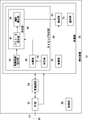
- FIG. 2 shows the configuration of the access control apparatus 10.
- the access control device 10 includes an antenna 20, an RF unit 22, a modem unit 24, a processing unit 26, a GPS positioning unit 28, and a control unit 30.
- the processing unit 26 includes a detection unit 32, a frame definition unit 34, and a generation unit 36.
- the detection unit 32 includes a power measurement unit 38, a quality measurement unit 40, an empty slot identification unit 42, and a collision slot identification unit 44. .
- the frame defining unit 34 divides each frame into a first period and a second period.
- the frame definition unit 34 generates a plurality of slots by dividing the first period into a plurality of times. For example, when the first period is “50 msec” and the slot is “500 ⁇ sec”, 100 slots are generated.
- the second period is defined as a period having a predetermined length, such as “50 msec”.
- each slot is defined to be composed of a plurality of OFDM symbols.
- the OFDM symbol is composed of a guard interval (GI) and a valid symbol.
- GI guard interval
- a guard time may be provided in the front part or the rear part of each slot.
- a group of a plurality of OFDM symbols included in the slot and a signal transmitted in the second period correspond to the aforementioned packet signal.
- CSMA / CA is executed by a plurality of terminal devices (not shown).
- FIGS. 3A to 3D show the frame format specified by the frame specifying unit 34.
- FIG. FIG. 3A shows the structure of the frame. As shown in the figure, it is defined that a plurality of frames are repeated such as the i-th frame to the (i + 2) -th frame. The period of each frame is “100 msec”, for example.
- FIG. 3B shows the configuration of one frame. As shown in the figure, one frame is composed of a first period and a second period, and the first period is composed of M slots. For example, the period of each slot is “500 ⁇ sec”.
- FIG. 3C shows the configuration of one slot. As shown in the figure, guard times are provided at the front portion and the rear portion of the slot. The remaining period of the slot is composed of N OFDM symbols.
- FIG. 3D shows the configuration of one OFDM symbol. As shown in the figure, one OFDM symbol is composed of a GI and an effective symbol. Returning to FIG.
- the RF unit 22 receives, from the antenna 20, a packet signal transmitted in communication between other terminal devices (not shown) in each slot of the first period or the second period as reception processing.
- the RF unit 22 performs frequency conversion on a radio frequency packet signal received via the antenna 20 to generate a baseband packet signal. Further, the RF unit 22 outputs a baseband packet signal to the modem unit 24.
- baseband packet signals are formed by in-phase and quadrature components, so two signal lines should be shown, but here only one signal line is shown for clarity. Shall be shown.
- the RF unit 22 includes an LNA (Low Noise Amplifier), a mixer, an AGC, and an A / D conversion unit. As a transmission process, the RF unit 22 performs frequency conversion on the baseband packet signal input from the modem unit 24 in each slot or second period of the first period, and generates a radio frequency packet signal. Further, the RF unit 22 transmits a radio frequency packet signal from the antenna 20.
- the RF unit 22 also includes a PA (Power Amplifier), a mixer, and a D / A conversion unit.
- the modem unit 24 demodulates the baseband packet signal from the RF unit 22 as a reception process. Further, the modem unit 24 outputs the demodulated result to the processing unit 26. The modem unit 24 also modulates the data from the processing unit 26 as a transmission process. Further, the modem unit 24 outputs the modulated result to the RF unit 22 as a baseband packet signal.
- the modem unit 24 since the communication system 100 corresponds to the OFDM modulation scheme, the modem unit 24 also executes FFT (Fast Fourier Transform) as a reception process, and also executes IFFT (Inverse Fast Fourier Transform) as a transmission process.
- FFT Fast Fourier Transform
- IFFT Inverse Fast Fourier Transform
- the power measuring unit 38 receives the received signal from the RF unit 22 or the modem unit 24 and measures the received power. Here, the received power is measured in slot units. Therefore, the power measuring unit 38 measures the received power for each of the plurality of slots. The power measuring unit 38 outputs the received power in slot units to the empty slot specifying unit 42 and the collision slot specifying unit 44.
- the quality measuring unit 40 receives the demodulation result from the modem unit 24 and measures the signal quality for each of the plurality of slots. Here, the error rate is measured as the signal quality. In addition, since a well-known technique should just be used for the measurement of an error rate, description is abbreviate
- EVM Error Vector Magnetode
- the quality measuring unit 40 outputs the error rate to the collision slot specifying unit 44.
- the empty slot identifying unit 42 receives the received power in slot units from the power measuring unit 38.
- the empty slot specifying unit 42 compares each received power with a threshold (hereinafter referred to as “empty slot threshold”), and specifies a slot whose received power is smaller than the empty slot threshold. That is, the empty slot specifying unit 42 detects, as an empty slot, a slot that can be used for communication between a plurality of terminal devices from a plurality of slots in the first period of the first period and the second period.
- the empty slot specifying unit 42 specifies them.
- the empty slot specifying unit 42 outputs information regarding the specified empty slot to the generating unit 36.
- the collision slot specifying unit 44 receives the received power for each slot from the power measuring unit 38 and receives the error rate for each slot from the quality measuring unit 40.
- the collision slot specifying unit 44 associates the received power with the error rate for each slot.
- the collision slot identifying unit 44 compares the received power with the first threshold value and compares the error rate with the second threshold value for each slot.
- the collision slot identifying unit 44 identifies, as a collision slot, a slot whose received power is larger than the first threshold and whose error rate is worse than the second threshold. That is, the collision slot specifying unit 44 recognizes a slot having a large received power but having deteriorated communication quality as a collision slot.
- the collision slot specifying unit 44 generates a collision when a plurality of terminal apparatuses transmit signals in duplicate from a plurality of slots in the first period of the first period and the second period.
- the detected slot is detected as a collision slot.
- the collision slot identification unit 44 outputs information regarding the identified collision slot to the generation unit 36.
- the generation unit 36 receives information on empty slots from the empty slot specifying unit 42 and receives information on collision slots from the collision slot specifying unit 44.
- the generation unit 36 generates control information while including information regarding empty slots and the identification number of the access control device 10.
- the generation unit 36 also stores parameters for deriving a period until transmission by CSMA / CA in the second period.
- the parameters include DIFS and CW.
- DIFS is one of IFS and is a period defined for determining whether or not a channel is in an idle state.
- each of the plurality of slots included in the first period is assigned a number (hereinafter referred to as “slot number”) that becomes “1” and “2” in order from the front.
- the generation unit 36 includes the slot number of the empty slot included in the previous frame as information on the empty slot in the control information.
- the generation unit 36 includes the slot number of the collision slot included in the previous frame as information on the collision slot in the control information.
- the frame defining unit 34 includes the first DIFS and the first CW (hereinafter collectively referred to as “parameter”) in the control information. Further, the generation unit 36 receives information on frames and slots from the frame definition unit 34 and periodically assigns control information to one slot included in each first period.
- control information is assigned to the slot of slot number “1” in each first period, that is, the first slot, and the generation unit 36 assigns control information to the slot.
- the generation unit 36 outputs control information to the modem unit 24 in the assigned slot.
- the generation unit 36 since the communication system 100 supports the OFDM modulation scheme, the generation unit 36 generates control information as an OFDM signal.
- An OFDM signal is also used for data communication between a plurality of terminal devices (not shown).
- control information an OFDM signal for arranging control information
- data an OFDM signal for arranging data
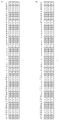
- FIG. 4A to 4B show the OFDM symbol formats used in the communication system 100.
- FIG. 4A corresponds to control information
- FIG. 4B corresponds to data.
- the vertical direction indicates the frequency and the horizontal direction indicates the time.
- numbers “31”, “30”,..., “ ⁇ 32” are shown in order from the top. These numbers are given to identify subcarriers (hereinafter referred to as “subcarriers”). Carrier number). Also, in the OFDM signal, the frequency of the subcarrier of subcarrier number “31” is the highest, and the frequency of the subcarrier of subcarrier number “ ⁇ 32” is the lowest.
- “D” corresponds to a data symbol
- P corresponds to a pilot symbol
- N corresponds to null.
- subcarriers with subcarrier numbers “31” to “27”, “2”, “0”, “ ⁇ 2”, “ ⁇ 26” to “ ⁇ 32” are null. is there.
- subcarriers with subcarrier numbers “26” to “3” and “ ⁇ 3” to “ ⁇ 25” are also used in data, and the use of symbols is the same for both.
- subcarrier numbers “1” and “ ⁇ 1” of the control information are not used in the data. These correspond to the aforementioned identification carrier. That is, the identification carrier is arranged on a subcarrier near the center frequency in the OFDM signal.
- a guard band is provided between the subcarrier used in the data and the identification carrier in the control information, that is, the subcarrier numbers “2” and “ ⁇ 2”.
- the subcarriers with subcarrier numbers “ ⁇ 2” to “2” may be collectively referred to as “identification carriers”.
- the generation unit 36 arranges information on empty slots and information on collision slots on subcarriers other than the identification carrier in the control information. Moreover, the production
- An example of information included in the control information is the latitude / longitude of the access control device 10 and the identification number of the access control device 10.
- a known signal is arranged in the OFDM symbol in front of the packet signal. Such a known signal is used for AGC in the terminal device and estimation of transmission path characteristics. The generation unit 36 may arrange the known signal on the identification carrier over a period of a part of the predetermined slot. Such a known signal is used like UW (Unique Word), for example.
- the modem unit 24 and the RF unit 22 notify the control information generated by the generation unit 36 from the antenna 20.
- the terminal device using the slot according to the information regarding the empty slot and the information regarding the collision slot included in the control information uses the slot corresponding to the slot over a plurality of frames. For example, the slot with the slot number “10” is continuously used.
- the control unit 30 controls processing of the entire access control apparatus 10.
- This configuration can be realized in terms of hardware by a CPU, memory, or other LSI of any computer, and in terms of software, it can be realized by a program loaded in the memory, but here it is realized by their cooperation.
- Draw functional blocks Accordingly, those skilled in the art will understand that these functional blocks can be realized in various forms by hardware only, software only, or a combination thereof.
- FIG. 5 shows the configuration of the terminal device 14 mounted on the vehicle 12.
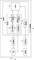
- the terminal device 14 includes an antenna 50, an RF unit 52, a modem unit 54, a processing unit 56, and a control unit 58.
- the processing unit 56 includes a timing specifying unit 60, an acquiring unit 62, a generating unit 64, and a notifying unit 70.
- the timing specifying unit 60 includes a control information extracting unit 66, a determining unit 80, a comparing unit 86, and a measuring unit 88.
- the determination unit 80 includes a parameter reception unit 94 and a period derivation unit 96.
- the antenna 50, the RF unit 52, and the modem unit 54 execute the same processing as the antenna 20, the RF unit 22, and the modem unit 24 in FIG. Therefore, these descriptions are omitted here.
- the acquisition unit 62 includes a GPS receiver (not shown), a gyroscope, a vehicle speed sensor, and the like. Based on data supplied from the GPS receiver, a vehicle 12 (not shown), that is, a vehicle 12 on which the terminal device 14 is mounted, Get direction, speed, etc. The existence position is indicated by latitude and longitude. Since a known technique may be used for these acquisitions, description thereof is omitted here.
- the acquisition unit 62 outputs the acquired information to the generation unit 64.
- the control information extraction unit 66 receives the demodulation result from the modem unit 54. Further, the control information extraction unit 66 monitors the subcarrier portion corresponding to the identification carrier in the demodulation result. When valid data is included in the subcarrier portion corresponding to the identification carrier, the control information extraction unit 66 recognizes that the slot including the control information is received. Further, the control information extraction unit 66 establishes frame and slot synchronization with reference to the timing at which the slot including the control information is received. As a result, the control information extraction unit 66 receives control information notified at a predetermined frequency from the access control device 10 (not shown).
- control information extraction unit 66 acquires information on empty slots and information on collision slots from the control information.
- the control information extraction unit 66 also acquires parameters and an identification number of the access control apparatus 10 (not shown) from the control information.
- the control information extraction unit 66 outputs information on empty slots, information on collision slots, and determination unit 80, outputs parameters to parameter reception unit 94, and outputs identification numbers to generation unit 64 via determination unit 80.
- the measuring unit 88 receives the control information reception signal from the RF unit 52 or the modem unit 54 and measures the received power.
- the measurement unit 88 outputs the received power to the comparison unit 86.
- the comparison unit 86 receives the received power from the measurement unit 88 and holds an area determination threshold value in advance.
- the comparison unit 86 compares the reception power with the area determination threshold value, and determines the use of the first period if the reception power is larger than the area determination threshold value. On the other hand, the comparison unit 86 determines to use the second period unless the received power is larger than the area determination threshold value.
- the comparison unit 86 outputs the determined content to the determination unit 80.
- the determination unit 80 receives the content determined in the comparison unit 86 from the comparison unit 86. In addition, the determination unit 80 receives information on empty slots and information on collision slots from the control information extraction unit 66. First, the determination unit 80 grasps whether to use the first period or the second period based on the information from the comparison unit 86. The determination unit 80 executes CSMA / CA (hereinafter referred to as “hereinafter referred to as“ CSMA / CA ”) regardless of the first period and the second period when the information from the comparison unit 86 is not received, that is, when the control information is not received. "Out-of-area operation"). Here, description will be made in the order of (1) using the first period, (2) using the second period, and (3) executing the operation outside the area.
- the determination unit 80 selects one empty slot based on the information regarding the empty slot. It should be noted that an empty slot may be selected arbitrarily.
- the determination unit 80 outputs information regarding the selected empty slot to the generation unit 64.
- the generation unit 64 receives information from the acquisition unit 62.
- the generation unit 64 generates data based on the information. Here, the data is formed as shown in FIG. Further, the generation unit 64 receives an instruction regarding an empty slot from the determination unit 80 and outputs data to the modem unit 54 in an empty slot corresponding to the instruction. Note that the processor 56 may perform carrier sense before outputting data. Further, the generation unit 64 outputs data in the slots having the same slot number even in the first period of the next frame. In that case, the production
- the control information extraction unit 66 continues to acquire information on empty slots and information on collision slots from the control information for each frame.
- the determination unit 80 confirms whether the slot number corresponding to the currently used slot is not a collision slot based on the information on the collision slot. If not determined as a collision slot, the determination unit 80 continues to output the same slot number as before to the generation unit 64. On the other hand, if the slot is determined to be a collision slot, the determination unit 80 selects one empty slot again based on the information regarding the empty slot. That is, a slot different from the slot selected so far is selected. The determination unit 80 outputs information regarding the selected empty slot to the generation unit 64. Thereafter, the generation unit 64 performs the same processing.
- the parameter receiving unit 94 receives parameters from the control information extracting unit 66.
- the parameter receiving unit 94 derives the parameters to the period deriving unit 96.
- the period deriving unit 96 stores the second DIFS and the second CW in advance, and derives a waiting period until the packet signal is transmitted based on the second DIFS and the second CW. Note that since a known technique may be used for deriving the waiting period, the description thereof is omitted here.
- the period deriving unit 96 derives a waiting period until a packet signal is transmitted based on the first DIFS and the first CW corresponding to the parameter.
- the waiting period until the packet signal is transmitted is specified by the DIFS and the back-off period, but the description is omitted here.
- the period deriving unit 96 preferentially uses the first DIFS and the first CW when the control information can be received, and uses the second DIFS and the second CW in the remaining cases. For this reason, when the second period is used, the first DIFS and the first CW are used. Also, the first DIFS and the first CW are set to values smaller than the second DIFS and the second CW, respectively. This corresponds to shortening the waiting period when control information can be received to be shorter than the remaining waiting period.
- the period deriving unit 96 outputs the derived period to the generating unit 64. That is, the period deriving unit 96 sets a waiting period until the packet signal is transmitted by CSMA in the generation unit 64.
- the processing unit 56 performs carrier sense in the second period. If the data can be transmitted as a result of the carrier sense, the generation unit 64 outputs the data to the modem unit 54 in the period set by the period derivation unit 96. Again, the generation unit 64 may include the identification number included in the received control information in the data. As a result, the modem unit 54, the RF unit 52, and the antenna 50 broadcast the packet signal in the period set in the period deriving unit 96 over the second period in which CSMA / CA is to be executed.
- the notification unit 70 acquires data from another terminal device 14 (not shown), and notifies the driver of the approach of another vehicle 12 (not shown) according to the contents of the data. The processing in the notification unit 70 is not limited to this.
- the period derivation unit 96 uses the second DIFS and the second CW to transmit the packet signal as in the case where the control information is not received. Deriving the waiting period. Moreover, the process part 56 detects reception of the packet signal from the other terminal device 14 alert
- the out-of-area terminal device transmits a packet signal by performing carrier sense while using the second DIFS and the second CW regardless of whether the terminal is in the first period.
- the processing unit 56 obtains the transmission source of the packet signal when the reception timing of the packet signal is shifted from the slot timing or when the identification number of the access control device 10 is not included in the received packet signal. Authorize it as an out-of-area terminal device.
- the processing unit 56 receives a packet signal from a terminal device outside the area, the processing unit 56 notifies the period deriving unit 96 to that effect.
- the period deriving unit 96 derives a waiting period until a packet signal is transmitted based on the first DIFS and the first CW, as described above.
- the generation unit 64, the modem unit 54, the RF unit 52, and the antenna 50 broadcast the packet signal in the period set in the period derivation unit 96 over the second period.
- the generation unit 64 includes information on the frame configuration in the packet signal.
- the information regarding the frame configuration includes, for example, the relative start time and end time of the first period relative to the current time, and the relative start time and end time of the second period.
- the generation unit 64 when the generation unit 64 detects a packet signal from an out-of-area terminal device, the generation unit 64 or the like switches the second DIFS and the second CW to the first DIFS and the first CW, respectively, and transfers the second DIFS and the second CW to the out-of-area terminal device.
- a packet signal for informing at least two periods is transmitted.
- the period deriving unit 96 sets the second DIFS and the second CW again after transmitting the packet signal.
- the second DIFS is 64 ⁇ sec
- the second CW is 0 to 16 and the slot period is 8 ⁇ sec
- the range between the DIFS period and the random backoff period is 64 to 192 ⁇ sec.
- the first DIFS is 16 ⁇ sec and the first CW is defined to be 0 to 5
- the range between the DIFS period and the random backoff period is 56 ⁇ sec or less. Therefore, the latter can transmit a packet signal before the former, and can notify the frame configuration.
- the determination unit 80 determines execution of the out-of-area operation. As described above, the period deriving unit 96 derives a waiting period until the packet signal is transmitted using the second DIFS and the second CW. The processing unit 56 performs carrier sense in a waiting period until a packet is transmitted, and the generation unit 64, the modem unit 54, the RF unit 52, and the antenna 50 transmit a packet signal. In addition, if the packet signal received via the antenna 50, the RF unit 52, and the modem unit 54 includes information on the frame configuration, the determining unit 80 extracts the information. Based on the information, the determination unit 80 specifies the second period and controls the generation unit 64 and the like so as to limit the transmission timing of the packet signal to the second period. The control unit 58 controls the operation of the entire terminal device 14.
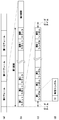
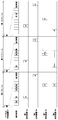
- FIG. 6 shows an operation outline of the communication system 100.
- the first terminal device 14a to the fourth terminal device 14d are shown, but these are not related to the positions of the first vehicle 12a to the fourth vehicle 12d in FIG.
- the second terminal device 14b is present in the second area 202 of FIG.
- the horizontal direction in the figure corresponds to time, and three frames from the i-th frame to the i + 2th frame are shown as described in the uppermost stage. For the sake of clarity, it is assumed that one frame includes 12 slots and a second period.
- the access control device 10 broadcasts control information in the first slot of each frame.
- “Control” in the figure corresponds to control information.
- information on empty slots and information on collision slots included in the control information are shown while being associated with the slots.
- “Empty” in the figure corresponds to an empty slot
- “attack” corresponds to a collision slot.
- the lower part shows the timing at which the first terminal device 14a to the fourth terminal device 14d notify the data.
- “De” in the figure corresponds to data.
- the first terminal device 14a, the third terminal device 14c, and the fourth terminal device 14d refer to the control information and select an empty slot.
- the first terminal device 14a, the third terminal device 14c, and the fourth terminal device 14d broadcast data in the selected empty slot.
- the empty slots selected in the third terminal device 14c and the fourth terminal device 14d are the same, the data notified from both collide.
- the access control device 10 detects the occurrence of a collision in the slot.
- the control information broadcast from the access control device 10 indicates the slot in which the collision occurred as information on the collision slot.
- reports data based on CSMA / CA in a 2nd period.
- the first terminal device 14a uses a slot having the same slot number again because no collision has occurred in the already used slot.
- the third terminal device 14c and the fourth terminal device 14d select another empty slot again because a collision has occurred in the already used slot.
- the third terminal device 14c and the fourth terminal device 14d notify the data in the selected empty slot. Since all data does not collide, the collision slot is not indicated in the control information broadcast from the access control apparatus 10 in the (i + 2) th frame. Therefore, in the (i + 2) th frame, the first terminal device 14a, the third terminal device 14c, and the fourth terminal device 14d use again the slot having the same slot number as the already used slot.
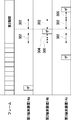
- FIG. 7 shows another operation outline of the communication system 100.
- FIG. 7 is shown similarly to FIG. In the uppermost stage, a frame including a first period and a second period composed of a plurality of slots is shown. Here, control information is omitted.
- the lower stage shows the timing which the 1st terminal device 14a alert
- the 1st terminal device 14a is the terminal device 14 which should operate
- the lower part shows the timing which the 2nd terminal device 14b alert
- the 2nd terminal device 14b is corresponded to the above-mentioned CSMA terminal device.
- the lowest level shows the timing at which the third terminal apparatus 14c notifies the data.
- the third terminal device 14c is the aforementioned out-of-area terminal device.
- the first terminal device 14a transmits data in a predetermined slot.
- the third terminal apparatus 14c since the third terminal apparatus 14c does not grasp the frame configuration, the third terminal apparatus 14c transmits data at a timing that crosses a plurality of slots regardless of the slot timing.
- the second access control device 10b receives data from the third terminal device 14c.
- the terminal device 14 (not shown) transmits data in the last slot of the first period
- the second DIFS 302 is set starting from the start timing of the second period in the first terminal device 14a and the third terminal device 14c.
- the second terminal device 14b since the second terminal device 14b has received the data from the third terminal device 14c, the first DIFS 300 and the back-off 304 are set. Thereafter, the second terminal device 14b transmits data. Since the data includes information on the frame configuration and the current time, the third terminal device 14c recognizes the timing at which the second period is arranged. Thereafter, after the second DIFS 302 has elapsed from the first terminal device 14a to the third terminal device 14c, the third terminal device 14c waits for the backoff 306 before transmitting data. The data is transmitted in the second period.
- FIG. 8 is a flowchart showing an empty slot notification procedure in the access control apparatus 10.
- the detection unit 32 sets the slot number m to 2 (S10).
- the power measuring unit 38 measures received power (S12). If the received power is smaller than the empty slot threshold (Y in S14), the empty slot specifying unit 42 specifies the slot with the slot number m as an empty slot (S16). If the received power is not smaller than the empty slot threshold (N in S14), the empty slot specifying unit 42 skips the process of step 16. If the slot number m is not the maximum number M (N in S18), the detection unit 32 adds 1 to the slot number m (S20) and returns to Step 12. On the other hand, if the slot number m is the maximum number M (Y in S18), the generation unit 36 includes the slot number of the empty slot in the control information (S22). The modem unit 24 and the RF unit 22 notify the control information (S24).
- FIG. 9 is a flowchart showing a collision slot notification procedure in the access control apparatus 10. Again, the subject of explanation is the first period.
- the detection unit 32 sets the slot number m to 2 (S40).
- the power measuring unit 38 measures the received power, and the quality measuring unit 40 measures the error rate (S42). If the received power is greater than the first threshold and the error rate is greater than the second threshold (Y in S44), the collision slot identifying unit 44 identifies the slot with the slot number m as a collision slot (S46). ). If the received power is not greater than the first threshold value or the error rate is not greater than the second threshold value (N in S44), the collision slot specifying unit 44 skips the process of step 46.
- the detection unit 32 adds 1 to the slot number m (S50), and returns to Step 42.
- the generation unit 36 includes the slot number of the collision slot in the control information (S52).
- the modem unit 24 and the RF unit 22 notify the control information (S54).
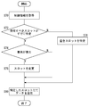
- FIG. 10 is a flowchart showing a procedure for determining the first period or the second period in the terminal device 14.
- the control information extraction unit 66 acquires control information (S160).
- the measuring unit 88 measures received power (S164). If the received power is larger than the area determining threshold value (Y in S166), the comparing unit 86 determines to use the first period (S168).
- the determination unit 80 executes communication by the slot (S172). If the received power is not greater than the area determining threshold value (N in S166), the comparing unit 86 determines to use the second period (S174).
- the determination unit 80 performs communication by CSMA / CA (S178). If control information is not acquired in step 160, the determination unit 80 determines to perform an out-of-area operation.
- FIG. 11 is a flowchart showing a data transmission procedure in the terminal device 14.
- the control information extraction unit 66 acquires control information (S70). If the slot to be used has already been identified (Y in S72), the determination unit 80 confirms whether or not a collision has occurred in the slot. If a collision has occurred (Y in S74), the determination unit 80 changes the slot (S76). If no collision has occurred (N in S74), step 76 is skipped. On the other hand, if the slot to be used is not already specified (N in S72), the determination unit 80 specifies an empty slot (S78). The generation unit 64 transmits data in the specified slot (S80).
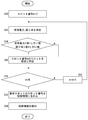
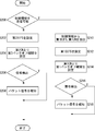
- FIG. 12 is a flowchart showing another data transmission procedure in the terminal device 14.
- the control information extraction unit 66 cannot receive the control information (N in S200)
- the determination unit 80 sets the second DIFS (S202).
- the determination unit 80 sets the second back-off period from the second CW (S204). If the processing unit 56 does not detect a signal by carrier sense (N in S206), the generation unit 64 and the like notify the packet signal (S208). If the processing unit 56 detects a signal by carrier sense (Y in S206), step 208 is skipped.
- the control information extracting unit 66 can receive the control information (Y in S200)
- the parameter receiving unit 94 extracts the first DIFS and the first CW from the control information (S210).
- the determination unit 80 sets the first DIFS (S212).
- the determination unit 80 sets the first back-off period from the first CW (S214). If the processing unit 56 does not detect a signal by carrier sense (N in S216), the generation unit 64 and the like notify the packet signal (S218). If the processing unit 56 detects a signal by carrier sense (Y in S216), step 218 is skipped.
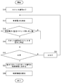
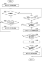
- FIG. 13 is a flowchart showing still another data transmission procedure in the terminal device 14.
- the determination unit 80 sets the second DIFS and the second CW (S230). If it is the first period (Y in S232) and data from outside the area is received (Y in S234), the determination unit 80 sets the first DIFS and the first CW (S236), and returns to Step 232.
- step 232 If data from outside the area is not received (N in S234), the process returns to step 232; If it is not the first period (N in S232) and there is no data to be transmitted (N in S238), the process returns to Step 232; On the other hand, if there is data to be transmitted (Y in S238) and the processing unit 56 does not detect the received power of the data within the IPS period (N in S240), the process returns to step S234.
- the processing unit 56 detects the received power of data within the IPS period (Y in S240), the period deriving unit 96 generates a random backoff period (S242). If the processing unit 56 does not detect the received power of data during the random backoff period (N in S244), the process returns to step 234. If the processing unit 56 detects the received power of data during the random backoff period (Y in S244), the generation unit 64 and the like transmit data (S246). If the notification of the frame configuration is completed (Y in S248), the determination unit 80 sets the second DIFS and the second CW (S250). If the notification of the frame configuration is not completed (N in S248), step 250 is skipped.
- the packet since the period until the packet signal when the control signal can be received is made smaller than the period until the packet signal when the control signal cannot be received, When the control signal can be received, the packet can be transmitted quickly. Further, since the first DIFS and the first CW are included in the control information from the access control device, the first DIFS and the first CW can be freely set. In addition, since the packet is transmitted quickly when the control signal can be received, the opportunity for transmission can be increased even if the transmission period is limited. When the packet signal from the out-of-area terminal device is detected, the period until the packet signal is notified is shortened, so that the opportunity for transmitting the packet signal can be increased. In addition, since the opportunity for transmitting the packet signal is increased, the frame configuration can be notified to the terminal device outside the area.
- a slot usable for communication between a plurality of terminal devices is notified from among a plurality of slots included in the first period, the probability of occurrence of a collision in communication between the plurality of terminal devices can be reduced.
- the probability of collision in communication between a plurality of terminal devices is reduced, the collision probability of packet signals can be reduced even when the amount of communication increases.
- empty slots are identified based on the received power for each of the plurality of slots, the identification can be easily performed.
- the number of the empty slot included in the previous frame is notified, the instruction to the terminal device can be surely executed.
- the terminal device using the empty slot uses a slot corresponding to the slot over a plurality of frames, the processing can be simplified.
- the access control device does not participate in the data communication between the terminal devices, but only notifies the index relating to the empty slot, it can be easily applied to a communication system based on CSMA / CA.
- a collision in communication between the plurality of terminal devices is reported.
- the probability of occurrence can be reduced.
- the collision slot is specified based on the received power for each of the plurality of slots and the signal quality for each of the plurality of slots, the specification can be easily performed.
- the instruction to the terminal device can be reliably executed.
- the access control apparatus since the access control apparatus does not participate in data communication between terminal apparatuses and only notifies an index related to a collision slot, the access control apparatus can be easily applied to a communication system based on CSMA / CA.
- the second period in the frame, it is possible to separate communication with high importance from communication with low importance. Moreover, since communication with high importance and communication with low importance are isolate
- the plurality of terminal apparatuses can be distributed to the first period or the second period.
- a plurality of terminal devices are distributed to the first period or the second period, it is possible to reduce the collision probability of packet signals in the first period.
- the area determination threshold value is used as the information regarding the terminal apparatus that should use a plurality of slots in the first period of the first period and the second period, the value can be easily adjusted. Further, since the area determination threshold value is used, the use of the first period or the second period can be designated even if the terminal device does not have a position positioning function.
- the identification carrier is not used for data, and the remaining subcarriers are also used for data. Therefore, even if the control information collides with the data signal, the signal component of the control information is observed. Thus, the presence of control information can be detected.
- a guard band is provided between the identification carrier and other subcarriers, interference between the two can be reduced, and the arrival probability of information transmitted on the identification carrier can be improved.
- important information is arranged on the identification carrier, the arrival probability of important information can be improved.
- UW is arrange
- control information notified from the access control device 10 and data notified from one terminal device 14 are allocated to one slot.
- control information and data may be assigned to two or more slots. According to this modification, the communication speed of control information and data can be improved.
- the identification carrier corresponds to two subcarriers. Further, the identification carrier is arranged on a subcarrier near the center frequency of the OFDM symbol. However, the present invention is not limited to this.
- the identification carrier may correspond to two or more subcarriers, and the identification carrier may be arranged on a subcarrier other than the vicinity of the center frequency of the OFDM symbol. According to this modification, the degree of freedom in designing the communication system 100 can be improved.
- the collision probability of packet signals can be reduced even when the amount of communication increases.
Landscapes
- Engineering & Computer Science (AREA)
- Signal Processing (AREA)
- Computer Networks & Wireless Communication (AREA)
- Mobile Radio Communication Systems (AREA)
- Traffic Control Systems (AREA)
Abstract
Description
決定部80は、空きスロットに関する情報をもとに、ひとつの空きスロットを選択する。なお、空きスロットの選択は、任意になされればよい。決定部80は、選択した空きスロットに関する情報を生成部64へ出力する。生成部64は、取得部62からの情報を受けつける。生成部64は、情報をもとにデータを生成する。ここで、データは、図4(b)のように形成される。また、生成部64は、決定部80から、空きスロットに関する指示を受けつけ、指示に応じた空きスロットにてデータを変復調部54へ出力する。なお、データを出力する前に、処理部56は、キャリアセンスを実行してもよい。また、生成部64は、次のフレームの第1期間においても、同一のスロット番号のスロットにおいてデータを出力する。その際、生成部64は、受信した制御情報に含まれた識別番号をデータに含めてもよい。
次に、第2期間を使用する場合を説明する。パラメータ受付部94は、制御情報抽出部66からパラメータを受けつける。パラメータ受付部94は、パラメータを期間導出部96へ導出する。期間導出部96は、第2DIFSと第2CWとを予め記憶し、第2DIFSと第2CWとをもとに、パケット信号を送信するまでの待ち期間を導出する。なお、待ち期間の導出には、公知の技術が使用されればよいので、ここでは説明を省略する。また、期間導出部96は、パラメータ受付部94からパラメータを受けつけた場合、パラメータに対応した第1DIFSと第1CWとをもとに、パケット信号を送信するまでの待ち期間を導出する。パケット信号を送信するまでの待ち期間は、DIFSとバックオフ期間によって特定されるが、ここでは説明を省略する。
さらに、エリア外動作を実行する場合を説明する。制御情報抽出部66が、所定の期間にわたって制御情報を受信できない場合に、決定部80は、エリア外動作の実行を決定する。期間導出部96は、前述のごとく、第2DIFSと第2CWとを使用して、パケット信号を送信するまでの待ち期間を導出する。処理部56は、パケットを送信するまでの待ち期間においてキャリアセンスを実行し、生成部64、変復調部54、RF部52、アンテナ50は、パケット信号を送信する。また、決定部80は、アンテナ50、RF部52、変復調部54を介して受信したパケット信号の中に、フレーム構成に関する情報が含まれていれば、当該情報を抽出する。決定部80は、当該情報をもとに、第2期間を特定し、パケット信号の送信タイミングを第2期間に限定するように、生成部64等を制御する。制御部58は、端末装置14全体の動作を制御する。
Claims (7)
- 搬送波感知多重アクセス方式にてパケット信号を報知するまでの時間間隔を設定する制御部と、
前記制御部において設定した時間間隔にてパケット信号を報知する通信部とを備え、
前記通信部は、無線装置間の通信を制御するアクセス制御装置から所定の頻度で報知される制御信号を受信し、
前記制御部は、前記通信部において制御信号を受信可能な場合の時間間隔を、残りの場合の時間間隔よりも短くすることを特徴とする無線装置。 - 前記通信部において受信した制御信号には、時間間隔を導出するためのパラメータが含まれており、
前記制御部は、時間間隔を導出するためのパラメータを予め記憶して、当該パラメータを使用するとともに、前記通信部において制御信号を受信した場合に、制御信号に含まれたパラメータを使用することを特徴とする請求項1に記載の無線装置。 - 前記通信部において受信した制御信号には、複数のスロットにて形成された第1期間と、所定の長さを有した第2期間とを含みながら繰り返されるフレームのうち、第1期間における複数のスロットの中から検出されたスロットであって、かつ複数の無線装置間の通信に使用可能なスロットに関する情報が含まれており、
前記通信部は、第2期間において、搬送波感知多重アクセス方式を実行することを特徴とする請求項1または2に記載の無線装置。 - 第1期間において、制御信号に含まれた情報にしたがわずに報知された他の無線装置からのパケット信号を検出する検出部をさらに備え、
前記通信部は、前記検出部がパケット信号を検出した場合に、時間間隔を短くして、前記他の無線装置へ第2期間を知らしめるためのパケット信号を送信することを特徴とする請求項3に記載の無線装置。 - 複数のスロットにて形成された第1期間と、所定の長さを有した第2期間とを含んだフレームが繰り返されるように規定され、第1期間と第2期間とのうちの第1期間における複数のスロットの中から、複数の他の無線装置間の通信に使用可能なスロットを検出する検出部と、
前記検出部において検出したスロットに関する情報を報知する報知部とを備え、
前記検出部における第2期間では、複数の他の無線装置によって搬送波感知多重アクセス方式がなされており、
前記報知部は、搬送波感知多重アクセス方式において送信までの時間間隔を導出させるためのパラメータも報知しており、報知しているパラメータによって導出される時間間隔が、他の無線装置が予め記憶しているパラメータによって導出される時間間隔よりも短くすることを特徴とする無線装置。 - 搬送波感知多重アクセス方式にてパケット信号を報知するまでの時間間隔を設定するステップと、
設定した時間間隔にてパケット信号を報知するステップとを備え、
前記設定するステップは、無線装置間の通信を制御するアクセス制御装置から所定の頻度で報知される制御信号を受信可能の時間間隔を、残りの場合の時間間隔よりも短くすることを特徴とする報知方法。 - 複数のスロットにて形成された第1期間と、所定の長さを有した第2期間とを含んだフレームが繰り返されるように規定され、第1期間と第2期間とのうちの第1期間における複数のスロットの中から、複数の他の無線装置間の通信に使用可能なスロットを検出するステップと、
検出したスロットに関する情報を報知するステップとを備え、
前記検出するステップにおける第2期間では、複数の他の無線装置によって搬送波感知多重アクセス方式がなされており、
前記報知するステップは、搬送波感知多重アクセス方式において送信までの時間間隔を導出させるためのパラメータも報知しており、報知しているパラメータによって導出される時間間隔が、他の無線装置が予め記憶しているパラメータによって導出される時間間隔よりも短くすることを特徴とする報知方法。
Priority Applications (3)
| Application Number | Priority Date | Filing Date | Title |
|---|---|---|---|
| CN2009801462541A CN102217398A (zh) | 2008-11-20 | 2009-11-20 | 广播方法以及无线装置 |
| US13/130,505 US8705561B2 (en) | 2008-11-20 | 2009-11-20 | Broadcasting method and radio apparatus |
| US14/196,819 US20140185514A1 (en) | 2008-11-20 | 2014-03-04 | Broadcasting method and radio apparatus |
Applications Claiming Priority (2)
| Application Number | Priority Date | Filing Date | Title |
|---|---|---|---|
| JP2008297150A JP5193823B2 (ja) | 2008-11-20 | 2008-11-20 | 報知方法および無線装置 |
| JP2008-297150 | 2008-11-20 |
Related Child Applications (2)
| Application Number | Title | Priority Date | Filing Date |
|---|---|---|---|
| US13/130,505 A-371-Of-International US8705561B2 (en) | 2008-11-20 | 2009-11-20 | Broadcasting method and radio apparatus |
| US14/196,819 Continuation US20140185514A1 (en) | 2008-11-20 | 2014-03-04 | Broadcasting method and radio apparatus |
Publications (1)
| Publication Number | Publication Date |
|---|---|
| WO2010058598A1 true WO2010058598A1 (ja) | 2010-05-27 |
Family
ID=42198041
Family Applications (1)
| Application Number | Title | Priority Date | Filing Date |
|---|---|---|---|
| PCT/JP2009/006278 Ceased WO2010058598A1 (ja) | 2008-11-20 | 2009-11-20 | 報知方法および無線装置 |
Country Status (4)
| Country | Link |
|---|---|
| US (2) | US8705561B2 (ja) |
| JP (1) | JP5193823B2 (ja) |
| CN (1) | CN102217398A (ja) |
| WO (1) | WO2010058598A1 (ja) |
Cited By (3)
| Publication number | Priority date | Publication date | Assignee | Title |
|---|---|---|---|---|
| CN102484815A (zh) * | 2010-08-09 | 2012-05-30 | 三洋电机株式会社 | 基站装置 |
| US20120188924A1 (en) * | 2011-01-26 | 2012-07-26 | Electronics And Telecommunications Research Institute | Method for controlling power in wireless ad-hoc network |
| EP2600641A4 (en) * | 2010-07-30 | 2017-10-18 | Panasonic Intellectual Property Management Co., Ltd. | Wireless device |
Families Citing this family (12)
| Publication number | Priority date | Publication date | Assignee | Title |
|---|---|---|---|---|
| CN102474702A (zh) * | 2010-06-14 | 2012-05-23 | 三洋电机株式会社 | 终端装置 |
| US8792470B2 (en) * | 2012-02-22 | 2014-07-29 | Zodiac Aerotechnics | Wireless network for aircraft cabin |
| JP5762997B2 (ja) * | 2012-02-29 | 2015-08-12 | 株式会社東芝 | 無線通信装置及び干渉検出方法 |
| US9407420B2 (en) * | 2013-03-15 | 2016-08-02 | Denso Corporation | Inter-vehicle communication system and inter-vehicle communication device |
| CN103618998B (zh) * | 2013-11-27 | 2016-07-13 | 同济大学 | 一种利用多信道csma实现多车辆同时广播信息的方法 |
| WO2015113204A1 (zh) * | 2014-01-28 | 2015-08-06 | 华为技术有限公司 | 一种数据传输方法及站点 |
| US10319224B2 (en) * | 2016-08-19 | 2019-06-11 | Veniam, Inc. | Adaptive road management in the network of moving things |
| JP7128104B2 (ja) * | 2018-12-20 | 2022-08-30 | ルネサスエレクトロニクス株式会社 | 半導体装置、無線端末装置、無線通信システムおよび無線端末装置の通信方法 |
| CN113228805B (zh) * | 2018-12-28 | 2024-01-16 | 三菱电机株式会社 | 无线通信装置、无线通信方法以及计算机能读取的记录介质 |
| WO2020144890A1 (ja) * | 2019-01-10 | 2020-07-16 | パナソニック インテレクチュアル プロパティ コーポレーション オブ アメリカ | 基地局、端末及び通信方法 |
| JP7128138B2 (ja) | 2019-03-15 | 2022-08-30 | ルネサスエレクトロニクス株式会社 | 半導体装置、無線端末装置および無線端末装置の通信方法 |
| WO2024107166A1 (en) * | 2022-11-14 | 2024-05-23 | Altiostar Network, Inc. | Efficient learning algorithm for channel estimation in wireless communication systems |
Citations (1)
| Publication number | Priority date | Publication date | Assignee | Title |
|---|---|---|---|---|
| JP2006033827A (ja) * | 2004-07-10 | 2006-02-02 | Mitsubishi Electric Research Laboratories Inc | 装置と前記装置の伝送範囲内の複数のコーディネータを備えた無線通信ネットワーク内の共通チャネルを通して伝送を同期させる方法 |
Family Cites Families (13)
| Publication number | Priority date | Publication date | Assignee | Title |
|---|---|---|---|---|
| US20020093929A1 (en) * | 2001-01-18 | 2002-07-18 | Koninklijke Philips Electronics N.V. | System and method for sharing bandwidth between co-located 802.11a/e and HIPERLAN/2 systems |
| ES2240352T3 (es) * | 2001-11-30 | 2005-10-16 | Telefonaktiebolaget Lm Ericsson (Publ) | Medida de la interferencia en un sistema de cominicaciones inalambrico. |
| US7471667B2 (en) * | 2002-01-09 | 2008-12-30 | Nxp B.V. | Coexistence of modulation schemes in a WLAN |
| US7548531B2 (en) * | 2002-12-16 | 2009-06-16 | Avaya Inc. | Poll scheduling for periodic traffic sources |
| JP4725036B2 (ja) | 2003-12-16 | 2011-07-13 | 株式会社デンソー | 通信装置、移動体用通信システム及びプログラム |
| JP4029833B2 (ja) | 2003-12-24 | 2008-01-09 | Kddi株式会社 | グループ管理方法、移動通信装置及びそのプログラム |
| WO2006011109A1 (en) | 2004-07-22 | 2006-02-02 | Philips Intellectual Property & Standards Gmbh | Scheduling the transmission of messages on a broadcast channel of an ad-hoc network dependent on the usage of this channel |
| JP2006295442A (ja) | 2005-04-08 | 2006-10-26 | Toyota Infotechnology Center Co Ltd | 通信方法および無線端末 |
| JP4802897B2 (ja) | 2006-07-07 | 2011-10-26 | 富士通株式会社 | 移動通信装置及びアドホック通信のチャネル切替え方法 |
| JP2008060984A (ja) | 2006-08-31 | 2008-03-13 | Nippon Telegr & Teleph Corp <Ntt> | 無線通信システムの送信装置および送信方法 |
| JP2008131490A (ja) | 2006-11-22 | 2008-06-05 | Matsushita Electric Ind Co Ltd | 無線タグ装置及び無線通信方法 |
| JP4895198B2 (ja) | 2007-01-26 | 2012-03-14 | Kddi株式会社 | 許容遅延時間を考慮した下りリンクの無線アクセス制御方法、アクセスポイント、端末及びプログラム |
| US7881340B2 (en) * | 2007-10-22 | 2011-02-01 | The Johns Hopkins University | Decentralized media access control for ad-hoc mobile wireless network |
-
2008
- 2008-11-20 JP JP2008297150A patent/JP5193823B2/ja active Active
-
2009
- 2009-11-20 US US13/130,505 patent/US8705561B2/en not_active Expired - Fee Related
- 2009-11-20 WO PCT/JP2009/006278 patent/WO2010058598A1/ja not_active Ceased
- 2009-11-20 CN CN2009801462541A patent/CN102217398A/zh active Pending
-
2014
- 2014-03-04 US US14/196,819 patent/US20140185514A1/en not_active Abandoned
Patent Citations (1)
| Publication number | Priority date | Publication date | Assignee | Title |
|---|---|---|---|---|
| JP2006033827A (ja) * | 2004-07-10 | 2006-02-02 | Mitsubishi Electric Research Laboratories Inc | 装置と前記装置の伝送範囲内の複数のコーディネータを備えた無線通信ネットワーク内の共通チャネルを通して伝送を同期させる方法 |
Non-Patent Citations (4)
| Title |
|---|
| KEITA KURAMOTO: "Kosaten Fukin no Sharyo no Anzen o Mokuteki to shita Real Time ITS Joho Tsushin System", IEICE TECHNICAL REPORT, vol. 106, no. 82, 22 May 2006 (2006-05-22), pages 35 - 39 * |
| MASATAKA OTA: "PDMA (Packet Division Multiple Access) ni Motozuku Doitsu Channel deno Daisho no Cell no Kasaneawase", IEICE TECHNICAL REPORT, vol. 104, no. 595, 20 January 2005 (2005-01-20), pages 119 - 122 * |
| TETSUYA FUNABASHI: "Hayawakari Koza", NIKKEI COMMUNICATIONS, no. 420, 15 August 2004 (2004-08-15), pages 102 - 103 * |
| TOMOHISA HARADA: "Jiritsu Bunsan Gata TDMA-sha Shakan Tsushin System no Kaihatsu", IPSJ SIG NOTES, vol. 2007, no. 116, 21 November 2007 (2007-11-21), pages 129 - 136 * |
Cited By (3)
| Publication number | Priority date | Publication date | Assignee | Title |
|---|---|---|---|---|
| EP2600641A4 (en) * | 2010-07-30 | 2017-10-18 | Panasonic Intellectual Property Management Co., Ltd. | Wireless device |
| CN102484815A (zh) * | 2010-08-09 | 2012-05-30 | 三洋电机株式会社 | 基站装置 |
| US20120188924A1 (en) * | 2011-01-26 | 2012-07-26 | Electronics And Telecommunications Research Institute | Method for controlling power in wireless ad-hoc network |
Also Published As
| Publication number | Publication date |
|---|---|
| US20110299487A1 (en) | 2011-12-08 |
| JP5193823B2 (ja) | 2013-05-08 |
| US8705561B2 (en) | 2014-04-22 |
| CN102217398A (zh) | 2011-10-12 |
| JP2010124330A (ja) | 2010-06-03 |
| US20140185514A1 (en) | 2014-07-03 |
Similar Documents
| Publication | Publication Date | Title |
|---|---|---|
| JP5193823B2 (ja) | 報知方法および無線装置 | |
| JP5389459B2 (ja) | 報知方法および無線装置 | |
| JP2014068378A (ja) | 通信方法および端末装置 | |
| JP5300460B2 (ja) | 無線装置 | |
| WO2010023945A1 (ja) | 報知方法ならびにそれを利用したアクセス制御装置および無線装置 | |
| JP5300459B2 (ja) | アクセス制御装置 | |
| JP2010130565A (ja) | 報知方法および無線装置 | |
| JP5340758B2 (ja) | 無線装置およびアクセス制御装置 | |
| JP5680237B2 (ja) | 送信方法および端末装置 | |
| JP5479564B2 (ja) | 送信方法および端末装置 | |
| WO2010073659A1 (ja) | 報知方法およびアクセス制御装置、無線装置 | |
| JP5199774B2 (ja) | 報知方法およびアクセス制御装置 | |
| JP5895176B2 (ja) | 送信方法および端末装置 | |
| JP5373174B2 (ja) | 通信方法および端末装置 | |
| JP5661131B2 (ja) | 通信方法および端末装置 | |
| JP5258440B2 (ja) | 報知方法およびアクセス制御装置 | |
| JP5502334B2 (ja) | 報知方法および無線装置 | |
| JP5394090B2 (ja) | 報知方法およびアクセス制御装置 | |
| JP5842114B2 (ja) | 端末装置、通信方法 | |
| JP5460825B2 (ja) | 送信方法およびアクセス制御装置 | |
| JP5657036B2 (ja) | 送信方法およびアクセス制御装置 | |
| JP5199775B2 (ja) | 報知方法およびアクセス制御装置 | |
| JP5657037B2 (ja) | 通信方法および端末装置 | |
| JP5258441B2 (ja) | 報知方法およびアクセス制御装置 | |
| JP5935052B2 (ja) | 通信方法および端末装置 |
Legal Events
| Date | Code | Title | Description |
|---|---|---|---|
| WWE | Wipo information: entry into national phase |
Ref document number: 200980146254.1 Country of ref document: CN |
|
| 121 | Ep: the epo has been informed by wipo that ep was designated in this application |
Ref document number: 09827379 Country of ref document: EP Kind code of ref document: A1 |
|
| NENP | Non-entry into the national phase |
Ref country code: DE |
|
| WWE | Wipo information: entry into national phase |
Ref document number: 13130505 Country of ref document: US |
|
| 122 | Ep: pct application non-entry in european phase |
Ref document number: 09827379 Country of ref document: EP Kind code of ref document: A1 |