WO2010055643A1 - 撮像装置 - Google Patents
撮像装置 Download PDFInfo
- Publication number
- WO2010055643A1 WO2010055643A1 PCT/JP2009/005996 JP2009005996W WO2010055643A1 WO 2010055643 A1 WO2010055643 A1 WO 2010055643A1 JP 2009005996 W JP2009005996 W JP 2009005996W WO 2010055643 A1 WO2010055643 A1 WO 2010055643A1
- Authority
- WO
- WIPO (PCT)
- Prior art keywords
- imaging
- optical axis
- image pickup
- imaging system
- subordinate
- Prior art date
- Legal status (The legal status is an assumption and is not a legal conclusion. Google has not performed a legal analysis and makes no representation as to the accuracy of the status listed.)
- Ceased
Links
Images


Classifications
-
- G—PHYSICS
- G03—PHOTOGRAPHY; CINEMATOGRAPHY; ANALOGOUS TECHNIQUES USING WAVES OTHER THAN OPTICAL WAVES; ELECTROGRAPHY; HOLOGRAPHY
- G03B—APPARATUS OR ARRANGEMENTS FOR TAKING PHOTOGRAPHS OR FOR PROJECTING OR VIEWING THEM; APPARATUS OR ARRANGEMENTS EMPLOYING ANALOGOUS TECHNIQUES USING WAVES OTHER THAN OPTICAL WAVES; ACCESSORIES THEREFOR
- G03B5/00—Adjustment of optical system relative to image or object surface other than for focusing
- G03B5/02—Lateral adjustment of lens
-
- G—PHYSICS
- G03—PHOTOGRAPHY; CINEMATOGRAPHY; ANALOGOUS TECHNIQUES USING WAVES OTHER THAN OPTICAL WAVES; ELECTROGRAPHY; HOLOGRAPHY
- G03B—APPARATUS OR ARRANGEMENTS FOR TAKING PHOTOGRAPHS OR FOR PROJECTING OR VIEWING THEM; APPARATUS OR ARRANGEMENTS EMPLOYING ANALOGOUS TECHNIQUES USING WAVES OTHER THAN OPTICAL WAVES; ACCESSORIES THEREFOR
- G03B17/00—Details of cameras or camera bodies; Accessories therefor
- G03B17/02—Bodies
-
- G—PHYSICS
- G03—PHOTOGRAPHY; CINEMATOGRAPHY; ANALOGOUS TECHNIQUES USING WAVES OTHER THAN OPTICAL WAVES; ELECTROGRAPHY; HOLOGRAPHY
- G03B—APPARATUS OR ARRANGEMENTS FOR TAKING PHOTOGRAPHS OR FOR PROJECTING OR VIEWING THEM; APPARATUS OR ARRANGEMENTS EMPLOYING ANALOGOUS TECHNIQUES USING WAVES OTHER THAN OPTICAL WAVES; ACCESSORIES THEREFOR
- G03B19/00—Cameras
-
- H—ELECTRICITY
- H04—ELECTRIC COMMUNICATION TECHNIQUE
- H04N—PICTORIAL COMMUNICATION, e.g. TELEVISION
- H04N23/00—Cameras or camera modules comprising electronic image sensors; Control thereof
- H04N23/45—Cameras or camera modules comprising electronic image sensors; Control thereof for generating image signals from two or more image sensors being of different type or operating in different modes, e.g. with a CMOS sensor for moving images in combination with a charge-coupled device [CCD] for still images
-
- H—ELECTRICITY
- H04—ELECTRIC COMMUNICATION TECHNIQUE
- H04N—PICTORIAL COMMUNICATION, e.g. TELEVISION
- H04N23/00—Cameras or camera modules comprising electronic image sensors; Control thereof
- H04N23/95—Computational photography systems, e.g. light-field imaging systems
- H04N23/951—Computational photography systems, e.g. light-field imaging systems by using two or more images to influence resolution, frame rate or aspect ratio
-
- H—ELECTRICITY
- H04—ELECTRIC COMMUNICATION TECHNIQUE
- H04N—PICTORIAL COMMUNICATION, e.g. TELEVISION
- H04N25/00—Circuitry of solid-state image sensors [SSIS]; Control thereof
- H04N25/48—Increasing resolution by shifting the sensor relative to the scene
-
- G—PHYSICS
- G02—OPTICS
- G02B—OPTICAL ELEMENTS, SYSTEMS OR APPARATUS
- G02B3/00—Simple or compound lenses
- G02B3/12—Fluid-filled or evacuated lenses
Definitions
- the present invention relates to an imaging apparatus using a plurality of imaging elements.
- a plurality of small and thin imaging systems with a relatively small number of pixels are used to image a common subject, and a plurality of obtained images are combined to increase the number of pixels and provide a high resolution.
- a compound eye imaging device that generates one image has been proposed (see, for example, Non-Patent Document 1).
- the compound-eye imaging apparatus includes two sets of imaging systems, a left imaging system and a right imaging system, and these two imaging systems capture the same subject with a sampling phase shifted by 1/2 pixel. Then, by synthesizing the two obtained images, an output image having a higher resolution than the images captured by the respective imaging systems is obtained.
- the sampling phase is a spatial phase at a position where the imaging element of each imaging system images when a subject is imaged by a plurality of imaging systems.
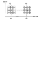
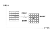
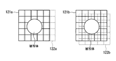
- the sampling phase will be described with reference to FIG. FIG. 20 shows the areas to be imaged by the left imaging system with grids 121a and 121b, the areas to be imaged with the right imaging system are shown by grids 122a and 122b (broken lines), and each of the smallest squares represents one pixel. Indicates an area to be imaged.
- the imaging positions of the pixels of the imaging elements of the two imaging systems substantially overlap, and the sampling phases are aligned.
- the areas captured by the pixels of the two imaging systems are shifted by 1/2 pixel in both the horizontal and vertical directions, and the sampling phase is in the horizontal and vertical directions. Both are shifted by 1/2 pixel.
- the sampling phase of the two imaging systems changes, and a phenomenon occurs in which the sampling phases are aligned depending on the imaging distance.
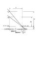
- FIG. 21 is a schematic diagram for explaining the change in sampling phase when the distance to the subject changes when the subject is imaged by two imaging systems.
- the image sensor M corresponds to the left imaging system
- the image sensor N corresponds to the right imaging system.
- the subject is located at the point P0 or the point P1, and is located on the optical axis of the image sensor M, that is, on the optical axis of the pinhole O.
- f is a focal length
- B is a baseline length.
- the shift amount on the imaging element N is about 3 ⁇ m from the equation (1).
- the instant in which the subject exists at the position of the imaging distance where the sampling phases are aligned 9 times occurs per second.
- such a problem is that even if the subject is stationary, if the subject has a depth, only a part of the subject can be high-resolution.
- a compound eye imaging device having a focal length f of 5 mm, a baseline length B of 12 mm, and a pixel pitch of 6 ⁇ m of an image sensor
- the sampling phase at an imaging distance of 700 mm is shifted by 1/2 pixel so that A is improved in resolution
- the sampling phase is 1 ⁇ 2 from the imaging distance of 700 mm at the imaging distance of 725 mm according to the equation (1).
- the present invention has been made in view of such circumstances, and an object of the present invention is to provide an imaging apparatus capable of generating a high-resolution image with a simple apparatus configuration without complicatedly controlling an optical system. To do.
- the present invention is a compound eye imaging device including M imaging systems (M is a natural number of 2 or more) having an optical system and an imaging device, and the imaging system includes one reference imaging system and M ⁇ 1 imaging systems.
- M is a natural number of 2 or more
- the image pickup surface of the image pickup device of the reference image pickup system and the image pickup surface of the image pickup device of the subordinate image pickup system are arranged in substantially the same plane, and the image pickup device of the reference image pickup system and the subordinate image pickup device
- the image pickup device of the image pickup system is arranged on a straight line substantially parallel to the pixel arrangement direction of the image pickup device, and when the length of one pixel of the image pickup device is W, L of the subordinate image pickup systems (L is the maximum)
- the imaging element of the subordinate imaging system whose value is M ⁇ 1 is a W ⁇ ((L / L / L / N) direction in a direction substantially orthogonal to the straight line with respect to the imaging element of the reference imaging system in the plane.
- the present invention is a compound eye imaging device including M imaging systems (M is a natural number of 2 or more) having an optical system and an imaging device, and the imaging system includes one reference imaging system and M ⁇ 1 imaging systems. And at least one of the subordinate imaging systems includes an optical axis control unit that controls an optical axis, the imaging surface of the imaging element of the reference imaging system, and the optical system
- the image pickup surface of the image pickup element of the subordinate image pickup system is arranged in substantially the same plane, and the image pickup element of the reference image pickup system and the image pickup element of the subordinate image pickup system are arranged on a straight line substantially parallel to the pixel arrangement direction of the image pickup element.
- the image sensor of the L-th sub-imaging system (L is a positive integer whose maximum value is M-1) among the sub-systems is By controlling the optical axis with the optical axis control unit, the imaging element of the reference imaging system substantially in the plane.
- W ⁇ ((L / M) + N) (N is a natural number including 0) characterized in that it is arranged at a distance with respect to.
- the arrangement direction of the one subordinate imaging system and the one reference imaging system is substantially the same as the arrangement direction of one subordinate imaging system different from the subordinate imaging system and the reference imaging system. It is characterized by being arranged orthogonally.
- the present invention is characterized in that the reference imaging system includes an optical member having substantially the same optical distance as the optical axis control unit.
- the optical axis control unit is configured by a non-solid lens capable of changing a refractive index distribution, and by changing the refractive index distribution of the non-solid lens, the light incident on the imaging element is changed.
- the optical axis is deflected.
- the optical axis control unit includes a refracting plate and an inclination angle changing unit that changes an inclination angle of the refracting plate, and the inclination angle changing unit changes the inclination angle of the refracting plate by the inclination angle changing unit.
- the optical axis of light incident on the image sensor is deflected.
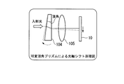
- the optical axis control unit includes a variable apex angle prism, and deflects an optical axis of light incident on the image sensor by changing an apex angle of the variable apex angle prism.
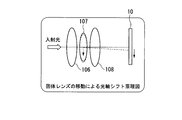
- the optical axis control unit includes a moving unit that moves the solid lens, and deflects an optical axis of light incident on the imaging element by moving the solid lens. .
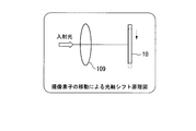
- the optical axis control unit includes a moving unit that moves the image sensor, and controls the optical axis of light incident on the image sensor by moving the image sensor. .
- an optical system is provided in a compound eye imaging device that generates a high-resolution image with a large number of pixels by imaging a common subject using a plurality of imaging systems and combining the obtained images.
- FIG. 21 is a schematic diagram for explaining the change in sampling phase when the distance to the subject changes when the subject is imaged by two imaging systems.
- each image pickup having a first image pickup system having an optical system (not shown) and an image pickup element M, and a second image pickup system having an optical system (not shown) and an image pickup element N.
- the system is configured such that the optical axis passes through the center of the image sensor.
- the sampling phase shift amount of the two imaging systems is u0-u1, which can be expressed by the above-described equation (1). . Therefore, the shift amount of the sampling phase when the imaging distance changes depends on the focal length f, the baseline length B, and the imaging distances H0 and H1. Therefore, in the present invention, by reducing the baseline length B of the plurality of imaging systems, the amount of sampling phase shift when the imaging distance changes is reduced, and the sampling phase is not controlled in accordance with the imaging distance. A configuration that can be resolved.
- the baseline length B is usually the distance between the optical axes of the two imaging systems.
- the base line length B is arranged in the same plane, and the pixel arrangement direction is the horizontal direction.
- the center-to-center distance (straight line distance) between two image sensors arranged in the vertical direction is the base line length B
- the distance between the horizontal components is the base line length BH
- the distance between the vertical components is the base line length BV.
- each image sensor is arranged on a substantially straight line in a substantially same plane, It is only necessary that the straight line and the pixel arrangement direction of each image sensor substantially coincide.
- FIG. 1 is a diagram showing a configuration of the embodiment.
- FIG. 1 is a diagram illustrating an arrangement of three imaging systems provided in the imaging apparatus according to the present embodiment.
- the three image pickup systems 11, 12, and 13 shown in FIG. 1 each have an optical system (not shown) constituted by a lens or the like and a two-dimensional array of image pickup elements.
- Each of the pixels of the image sensor included in each of the imaging systems 11, 12, and 13 is substantially square.
- one imaging element is described as being a 5 ⁇ 5 two-dimensional array.
- an actual imaging apparatus includes a two-dimensional array imaging element having, for example, 640 (horizontal) ⁇ 480 (vertical) pixels. Etc. are used.
- the image pickup system 11 (referred to as a reference image pickup system) and the image pickup system 12 (referred to as a subordinate image pickup system) shown in FIG. 1 are arranged side by side so as to be substantially horizontal, and the center of the image pickup element is the two image pickup systems. 11 and 12 are shifted by 1/2 pixel in the vertical direction orthogonal to the horizontal direction, and the base line length BV in the vertical direction is 1/2 pixel.
- the imaging system 11 and the imaging system 13 (referred to as a subordinate imaging system) are arranged side by side so as to be substantially vertical, and the center of the imaging element is the direction in which these two imaging systems are arranged, that is, vertical.
- the base line length BH in the horizontal direction is 1/2 pixel.
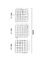
- FIG. 2 shows a state in which the sampling phases of the imaging system 11 and the imaging system 13 arranged substantially vertically are shifted with changes in the imaging distance.
- FIG. 2 shows the state of the sampling phase when the imaging distance becomes longer in the order of left, center, and right.
- the sampling phase in the vertical direction gradually shifts as the imaging distance changes.
- the sampling phase in the horizontal direction maintains a state where it is shifted by 1/2 pixel regardless of the imaging distance.
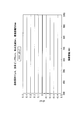
- FIG. 3 shows the horizontal sampling phase when the imaging distance is changed to H1 when the pixel pitch of the imaging element is 6 ⁇ m, the focal length f is 5 mm, the base length BH is 3 ⁇ m, and the imaging distance H0 is 500 mm.
- FIG. 3 shows the horizontal sampling phase when the imaging distance is changed to H1 when the pixel pitch of the imaging element is 6 ⁇ m, the focal length f is 5 mm, the base length BH is 3 ⁇ m, and the imaging distance H0 is 500 mm.
- the shift amount u0-u1 is substantially 0 regardless of the imaging distance.
- the base line length BH is set to a length corresponding to 1/2 pixel of the image sensor and the sampling phase shift between the two imaging systems is set to 1/2 pixel, the imaging system 11 and the imaging system even if the imaging distance changes.
- the 13 horizontal sampling phase shifts can be approximately 1 ⁇ 2 pixel.
- the base line length BH is not limited to the length corresponding to 1/2 pixel, and as represented by the formula (2), 3/2 pixels, 5/2 pixels, 7/2 pixels, and 9/2. By using pixels, the shift amount of the sampling phase in the horizontal direction can be made substantially zero even when the imaging distance changes.
- BH (length of one pixel of image sensor) ⁇ (2N + 1) / 2 (2)
- N is a natural number including 0, and is preferably a small value.
- the focal length f is 5 mm
- the imaging distance H0 is 500 mm
- the base line length BH is 21 ⁇ m, that is, the base line length BH is 7/2 pixels infinite.
- the shift amount of the sampling phase at can be calculated as 0.035 pixels from the equation (2). If the sampling phase shift at the imaging distance H0 is 1 ⁇ 2 pixel, it becomes almost 1 ⁇ 2 pixel even at infinity. Therefore, if the base line length BH is set to the state of the expression (2), the sampling phase is almost shifted by 1/2 pixel even if the imaging distance is changed, and the high resolution can be obtained without a complicated control device. Can be imaged.
- the high resolution in the horizontal direction by the two imaging systems 11 and 13 arranged substantially vertically has been described.
- the high resolution in the vertical direction is also set to 2 arranged almost horizontally.
- the two imaging systems may be arranged so that the base line length BV in the vertical direction of the two imaging systems 11 and 12 is a length that can be expressed by the expression (3).
- BV (length of one pixel of the image sensor) ⁇ (2N + 1) / 2 (3)
- N is a natural number including 0, and is preferably a small value.
- the imaging system 11 shown in FIG. 1 is used as a reference imaging system, and the imaging system 12 can be highly resolved either on the left or right in the horizontal direction, and the imaging system 13 on either the top or bottom in the vertical direction ((2) If the arrangement is made so as to satisfy the equation (3), it is possible to achieve high resolution in both the horizontal and vertical directions with the configuration of the three imaging systems 11, 12, and 13.
- the image of the image pickup system 11 that is the reference image pickup system is a reference image
- the three image pickup systems 11, 12, and 13 each use an image pickup device of 5 ⁇ 5 pixels.
- the pixels of the image of the imaging system 12 that are shifted by 1/2 pixel in the vertical direction are embedded between the pixels arranged in the vertical direction of the reference image.
- the pixels of the image of the imaging system 13 that are shifted by 1/2 pixel in the horizontal direction are embedded between the pixels arranged in the horizontal direction of the reference image. Since the image is only 75 pixels as it is, the remaining 25 pixels are pixels of the image obtained by the imaging system 12 and the imaging system 13 with respect to the reference image obtained by the imaging system 11. In the embedded state, a pixel value is obtained by complementing the surrounding pixel values, and an image with a higher resolution is generated by embedding pixels of the obtained pixel value.
- This image composition process is an example, and a known image composition process can be applied.
- the horizontal sampling phase of the two imaging systems arranged substantially vertically is shifted by 1 ⁇ 2 pixel to achieve high resolution in the horizontal direction, and 2 arranged almost horizontally.
- the configuration has been described in which the vertical sampling phase of one imaging system is shifted by 1 ⁇ 2 pixel to increase the resolution in the vertical direction, the number of imaging systems to be arranged may be three or more.
- the state where the sampling phase is shifted by 1/2 pixel is optimal for high resolution, but when high resolution is achieved with three or more imaging systems, one direction
- a state in which the sampling phase is shifted by 1 / M pixels is optimal for high resolution.
- the imaging system 51 is a reference imaging system, and the other two subordinate imaging systems are imaging systems 52, 53.
- the state in which the sampling phase is shifted by 1/3 pixel and 2/3 pixel in the horizontal direction is most suitable for high resolution.
- the base line length BH in the horizontal direction of the L-th subordinate imaging system of the subordinate imaging system may satisfy the equation (4).
- BH (length of one pixel of image sensor) ⁇ ((L / M) + N) (4)
- L is a positive integer whose maximum value is M ⁇ 1
- N is a natural number including 0. At this time, it is desirable that N is a small value.
- BV (length of one pixel of the image sensor) ⁇ ((L / M) + N) (5)
- L is a positive integer whose maximum value is M ⁇ 1
- N is a natural number including 0. At this time, it is desirable that N is a small value.
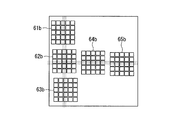
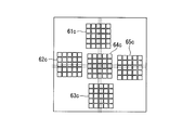
- FIG. 5 shows that the first sub imaging system 62a and the second sub imaging system 63a are in the vertical direction, and the first sub imaging system 64a and the second sub imaging system 65a are in the horizontal direction.
- the horizontal base lengths BH of the subordinate imaging systems 62a and 63a with respect to the reference imaging system 61a are 1/3 pixel and 2/3 pixel, respectively.
- the base line lengths BH in the vertical direction of the slave imaging systems 64a and 65a with respect to the reference imaging system 61a are 1/3 pixel and 2/3 pixel, respectively.
- the imaging systems 62 b and 63 b that are subordinate imaging systems with the imaging system 61 b as a reference imaging system are arranged in the vertical direction, and the imaging systems 64 b and 65 b that are subordinate imaging systems are arranged in the horizontal direction with the imaging system 62 b as the reference imaging system.
- the horizontal base lengths BH of the subordinate imaging systems 62b and 63b with respect to the reference imaging system 61b are 1/3 pixel and 2/3 pixel, respectively.
- the base line lengths BV in the vertical direction of the dependent imaging systems 64b and 65b with respect to the reference imaging system 62b are 1/3 pixel and 2/3 pixel, respectively.
- the imaging systems 64 c and 63 c that are the subordinate imaging systems with the imaging system 61 c as the reference imaging system are arranged in the vertical direction, and the imaging systems 64 c and 65 c that are the subordinate imaging systems are arranged in the horizontal direction with the imaging system 62 c as the reference imaging system.
- the horizontal base lengths BH of the subordinate imaging systems 64c and 63c with respect to the reference imaging system 61c are 1/3 pixel and 2/3 pixel, respectively.
- the base line lengths BV in the vertical direction of the slave imaging systems 64c and 65c with respect to the reference imaging system 62c are 1/3 pixel and 2/3 pixel, respectively.
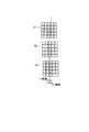
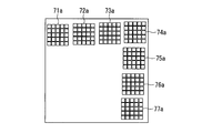
- FIG. 8 shows an example in which the subordinate imaging systems 75a, 76a, and 77a are arranged in the vertical direction with the imaging system 74a as the reference imaging system, and the subordinate imaging systems 71a, 72a, and 73a are arranged in the horizontal direction with the imaging system 74a as the reference imaging system.
- the horizontal base lengths BH of the subordinate imaging systems 75a, 76a, and 77a with respect to the reference imaging system 74a are 1/4 pixel, 2/4 pixel, and 3/4 pixel, respectively.
- the base line lengths BV in the vertical direction of the slave imaging systems 71a, 72a, 73a with respect to the reference imaging system 74a are 1/4 pixel, 2/4 pixel, and 3/4 pixel, respectively.
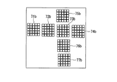
- FIG. 9 shows an example in which the subordinate imaging systems 73b, 76b, and 77b are arranged in the vertical direction using the imaging system 75b as the reference imaging system, and the subordinate imaging systems 72b, 73b, and 74b are arranged in the horizontal direction using the imaging system 71b as the reference imaging system.
- the horizontal base lengths BH of the subordinate imaging systems 73b, 76b, and 77b with respect to the reference imaging system 75b are 1/4 pixel, 2/4 pixel, and 3/4 pixel, respectively.
- the base line lengths BV in the vertical direction of the dependent imaging systems 72b, 73b, and 74b with respect to the reference imaging system 71b are 1/4 pixel, 2/4 pixel, and 3/4 pixel, respectively.
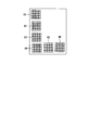
- FIG. 10 shows an example in which the subordinate imaging systems 72c, 73c, and 74c are arranged in the vertical direction using the imaging system 71c as the reference imaging system, and the subordinate imaging systems 75c, 76c, and 77c are arranged in the horizontal direction using the imaging system 73c as the reference imaging system.
- the base line lengths BH in the horizontal direction of the dependent imaging systems 72c, 73c, and 74c with respect to the reference imaging system 71c are 1/4 pixel, 2/4 pixel, and 3/4 pixel, respectively.
- the base line lengths BV in the vertical direction of the dependent imaging systems 75c, 76c, and 77c with respect to the reference imaging system 73c are 1/4 pixel, 2/4 pixel, and 3/4 pixel, respectively.
- the number of image pickup systems arranged in the horizontal direction may be different from the number of image pickup systems arranged in the vertical direction.
- the sampling in the horizontal direction of the four imaging systems 81, 82, 83, 84 arranged in the vertical direction is performed.
- the phase may be shifted by 1/4 pixel, and the vertical sampling phase of the three imaging systems 84, 85, 86 arranged in the horizontal direction may be shifted by 1/3 pixel.
- the high resolution image composition processing is the same as the processing described in the first embodiment, and the imaging system is shifted by 1 / M pixel in the vertical direction between pixels arranged in the vertical direction of the reference image. Each of the plurality of image pixels is embedded. Further, pixels of a plurality of images of the imaging system that are shifted by 1 / M pixel in the horizontal direction are embedded between the pixels arranged in the horizontal direction of the reference image. For the remaining pixels, pixel values are obtained by complementing the surrounding pixel values, and an image with a higher resolution is generated by embedding the pixels having the obtained pixel values. In this case as well, a known image composition process can be applied.
- a third embodiment of the present invention will be described.
- the imaging apparatus by arranging the imaging system as described in the first and second embodiments, it is possible to capture an image with a sampling phase that can always achieve high resolution without complicated control of the optical system.
- Each imaging system is provided with an optical axis control unit for controlling the optical axis, and the optical axis control unit adjusts the optical axis of each imaging system, thereby substantially substituting the equations (2), (3), (
- the sampling phase that can achieve high resolution may be controlled so as to satisfy the conditions expressed by equations (4) and (5). For example, as shown in FIG.
- the vertical base line length BV of two imaging systems 201 and 202 arranged horizontally is 0, but the optical axis 204 of the imaging system 202 is set to 1 in the vertical direction by the optical axis control unit.
- the baseline length BV is apparently 1 ⁇ 2 pixel, and the sampling phase can be increased.
- the optical axis of each imaging system is adjusted by the optical axis control unit, and each imaging system is substantially set to the expressions (2), (3), (4), and (5).
- a liquid crystal lens can be used as the optical axis control unit.
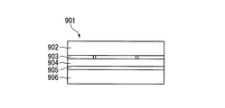
- 13 and 14 show the configuration of the liquid crystal lens 901.
- FIG. FIG. 13 is a side view of the liquid crystal lens 901
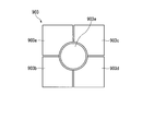
- FIG. 14 is a front view of the liquid crystal lens 901 shown in FIG.
- the liquid crystal lens 901 has a structure in which a glass substrate 902, an electrode 903, a liquid crystal layer 904, an electrode 905, and a glass substrate 906 are stacked.
- the electrode 903 is divided into five electrodes 903a, 903b, 903c, 903d, and 903e.
- An electric field is generated between the two electrodes 903 and 905 by applying a voltage to the electrodes 903 and 905 of the liquid crystal lens 901.
- the liquid crystal molecules of the liquid crystal layer 904 are aligned in the direction of this electric field.
- a refractive index distribution is generated in the liquid crystal layer 904, and it can function as a lens.
- the optical axis control unit adjusts the optical axis with respect to the reference imaging system, and therefore may be provided in the subordinate imaging system, and may not be provided in the reference imaging system. Further, when the reference imaging system does not have an optical axis control unit, the optical distance to the subject is slightly different from that of the subordinate imaging system, so that an optical member having substantially the same optical distance as the optical axis control unit in the subordinate imaging system, For example, by using glass or the like for the reference imaging system, the imaging system can be arranged in the same plane, and the arrangement becomes easy.
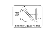
- the optical axis shift amount by the refracting plate 103 changes depending on the inclination angle, the position incident on the image sensor 10 changes, and the optical axis shift becomes possible.
- the direction of the optical axis shift caused by tilting the refracting plate 103 is only one axis direction (vertical direction in the figure)
- a refracting plate that shifts the optical axis in the horizontal direction is separately arranged. As a result, the optical axis can be shifted in the biaxial direction, and the optical axis can be shifted in any direction within the image sensor surface.
- FIG. 16 is a diagram showing a configuration for controlling the optical axis by using the variable apex angle prism 104 and the solid lens 105.
- the incident light is deflected by changing the apex angle of the variable apex angle prism 104 by means such as an actuator using a piezoelectric element.
- the position changes and the optical axis can be shifted.
- the optical axis shift direction is only one axial direction (vertical direction in the figure) as shown in FIG. 16, so a variable vertical angle prism that shifts the optical axis in the horizontal direction is arranged separately.
- the optical axis can be shifted in an arbitrary direction.
- FIG. 17 is a diagram showing a configuration in which the optical axis is controlled by moving all or part of the solid lenses 106, 107, and 108 in a direction substantially perpendicular to the optical axis by a moving means such as an actuator using a piezoelectric element. is there.
- the optical system is composed of three solid lenses 106, 107, and 108.
- the solid lens 107 which is a part of the optical system, is moved horizontally by an actuator using a piezoelectric element that can move in the vertical direction. It is moved by a moving means by an actuator using a piezoelectric element movable in the direction. As shown in FIG.
- FIG. 18 is a diagram in which the image sensor 10 is directly moved by a moving means such as an actuator using a piezoelectric element.
- the optical axis shift amount is controlled not on the optical system 109 but on the image sensor 10.
- the image pickup device 10 is moved by a moving means using an actuator using a piezoelectric element moving in the vertical direction and a moving means using an actuator using a piezoelectric element moving in the horizontal direction. Since the imaging position on 10 moves, the optical axis can be shifted independently in the vertical and horizontal directions.
- the piezoelectric element is used as the actuator as the moving means of the optical system and the moving means of the imaging device, but the present invention is not limited to this, and the solenoid actuator, motor and gear mechanism using electromagnetic force are not limited thereto. Means such as an actuator using a pressure, an actuator using pressure, or the like can also be used.
- the optical axis shift direction the vertical direction and the horizontal direction have been described, but the present invention is not limited to this.
- the optical axis control unit shown in FIGS. 15 to 17 shifts the optical axis by deflecting the light incident on each imaging system, so that each imaging system is apparently expressed by equations (2), (3), (4 ) And (5). Further, by moving the image sensor 10 by the optical axis control unit shown in FIG. 18, the same effect as the optical axis shift can be obtained.
- a plurality of imaging systems are arranged on a straight line in a substantially vertical direction and a substantially horizontal direction, and the conditional expression (Equation (2)) that enables each imaging system to have high resolution in a direction perpendicular to the arrangement direction.
- conditional expression (Equation (2)) that enables each imaging system to have high resolution in a direction perpendicular to the arrangement direction.
- (3), (4), and (5)) are arranged at a distance that satisfies the above conditions, so that high resolution is obtained in a direction perpendicular to the linear direction without complicated control of the optical system.
- an optical axis control unit that statically moves the direction of the optical axis is provided, and the optical axis is shifted by deflecting light incident on each imaging system by this optical axis control unit. Since control is performed so as to satisfy the conditional expressions (formula (2), formula (3), formula (4), formula (5)) that can achieve high resolution, high resolution can be achieved without complicated control of the optical system.
Landscapes
- Engineering & Computer Science (AREA)
- Physics & Mathematics (AREA)
- General Physics & Mathematics (AREA)
- Multimedia (AREA)
- Signal Processing (AREA)
- Computing Systems (AREA)
- Theoretical Computer Science (AREA)
- Human Computer Interaction (AREA)
- Studio Devices (AREA)
- Transforming Light Signals Into Electric Signals (AREA)
- Mounting And Adjusting Of Optical Elements (AREA)
- Cameras In General (AREA)
Priority Applications (3)
| Application Number | Priority Date | Filing Date | Title |
|---|---|---|---|
| US13/128,568 US20110211097A1 (en) | 2008-11-12 | 2009-11-10 | Imaging device |
| CN2009801446290A CN102210135A (zh) | 2008-11-12 | 2009-11-10 | 摄像装置 |
| EP09825897.3A EP2352277A4 (en) | 2008-11-12 | 2009-11-10 | IMAGING DEVICE |
Applications Claiming Priority (2)
| Application Number | Priority Date | Filing Date | Title |
|---|---|---|---|
| JP2008-289618 | 2008-11-12 | ||
| JP2008289618A JP2010118818A (ja) | 2008-11-12 | 2008-11-12 | 撮像装置 |
Publications (1)
| Publication Number | Publication Date |
|---|---|
| WO2010055643A1 true WO2010055643A1 (ja) | 2010-05-20 |
Family
ID=42169789
Family Applications (1)
| Application Number | Title | Priority Date | Filing Date |
|---|---|---|---|
| PCT/JP2009/005996 Ceased WO2010055643A1 (ja) | 2008-11-12 | 2009-11-10 | 撮像装置 |
Country Status (5)
| Country | Link |
|---|---|
| US (1) | US20110211097A1 (enExample) |
| EP (1) | EP2352277A4 (enExample) |
| JP (1) | JP2010118818A (enExample) |
| CN (1) | CN102210135A (enExample) |
| WO (1) | WO2010055643A1 (enExample) |
Families Citing this family (9)
| Publication number | Priority date | Publication date | Assignee | Title |
|---|---|---|---|---|
| US8391563B2 (en) * | 2010-05-25 | 2013-03-05 | Sony Corporation | Using computer video camera to detect earthquake |
| WO2013118305A1 (ja) * | 2012-02-10 | 2013-08-15 | シャープ株式会社 | 画像生成装置、画像生成方法、および画像生成プログラムを記録したコンピュータ読取り可能な記録媒体 |
| JP6068010B2 (ja) * | 2012-06-07 | 2017-01-25 | 日立マクセル株式会社 | 顕微鏡システム |
| CN105308951A (zh) * | 2013-06-17 | 2016-02-03 | 柯尼卡美能达株式会社 | 定位装置、定位方法及复眼照相机组件 |
| US10558036B2 (en) * | 2015-12-15 | 2020-02-11 | Facebook Technologies, Llc | Using oscillation of optical components to reduce fixed pattern noise in a virtual reality headset |
| US9886742B2 (en) * | 2016-03-17 | 2018-02-06 | Google Llc | Electro-optic beam steering for super-resolution/lightfield imagery |
| JP2019029913A (ja) * | 2017-08-01 | 2019-02-21 | キヤノン株式会社 | 撮像装置 |
| US11032470B2 (en) * | 2018-08-30 | 2021-06-08 | Intel Corporation | Sensors arrangement and shifting for multisensory super-resolution cameras in imaging environments |
| JPWO2022107860A1 (enExample) * | 2020-11-20 | 2022-05-27 |
Citations (6)
| Publication number | Priority date | Publication date | Assignee | Title |
|---|---|---|---|---|
| JPH07322149A (ja) * | 1994-05-20 | 1995-12-08 | Canon Inc | 撮像装置 |
| JP2000244932A (ja) * | 1999-02-19 | 2000-09-08 | Mitsubishi Electric Corp | 撮像装置及び撮像方法 |
| WO2006064751A1 (ja) * | 2004-12-16 | 2006-06-22 | Matsushita Electric Industrial Co., Ltd. | 複眼撮像装置 |
| WO2007013250A1 (ja) * | 2005-07-26 | 2007-02-01 | Matsushita Electric Industrial Co., Ltd. | 複眼方式の撮像装置 |
| JP2007520166A (ja) * | 2004-01-26 | 2007-07-19 | ディジタル・オプティックス・コーポレイション | サブピクセル解像度を有する薄型カメラ |
| JP2008289618A (ja) | 2007-05-23 | 2008-12-04 | Toto Ltd | 折り畳み式棚及び折り畳み式棚を備える洗面化粧台 |
Family Cites Families (5)
| Publication number | Priority date | Publication date | Assignee | Title |
|---|---|---|---|---|
| US6018363A (en) * | 1994-04-28 | 2000-01-25 | Canon Kabushiki Kaisha | Image sensing apparatus with optical-axis deflecting device |
| DE19803064C1 (de) * | 1998-01-28 | 1999-07-29 | Daimler Chrysler Ag | Optisches Aufklärungssystem |
| JP2002209226A (ja) * | 2000-12-28 | 2002-07-26 | Canon Inc | 撮像装置 |
| JP4071793B2 (ja) * | 2003-10-22 | 2008-04-02 | 松下電器産業株式会社 | 撮像装置とその製造方法、及び携帯機器 |
| US20090268983A1 (en) * | 2005-07-25 | 2009-10-29 | The Regents Of The University Of California | Digital imaging system and method using multiple digital image sensors to produce large high-resolution gapless mosaic images |
-
2008
- 2008-11-12 JP JP2008289618A patent/JP2010118818A/ja active Pending
-
2009
- 2009-11-10 WO PCT/JP2009/005996 patent/WO2010055643A1/ja not_active Ceased
- 2009-11-10 CN CN2009801446290A patent/CN102210135A/zh active Pending
- 2009-11-10 US US13/128,568 patent/US20110211097A1/en not_active Abandoned
- 2009-11-10 EP EP09825897.3A patent/EP2352277A4/en not_active Withdrawn
Patent Citations (6)
| Publication number | Priority date | Publication date | Assignee | Title |
|---|---|---|---|---|
| JPH07322149A (ja) * | 1994-05-20 | 1995-12-08 | Canon Inc | 撮像装置 |
| JP2000244932A (ja) * | 1999-02-19 | 2000-09-08 | Mitsubishi Electric Corp | 撮像装置及び撮像方法 |
| JP2007520166A (ja) * | 2004-01-26 | 2007-07-19 | ディジタル・オプティックス・コーポレイション | サブピクセル解像度を有する薄型カメラ |
| WO2006064751A1 (ja) * | 2004-12-16 | 2006-06-22 | Matsushita Electric Industrial Co., Ltd. | 複眼撮像装置 |
| WO2007013250A1 (ja) * | 2005-07-26 | 2007-02-01 | Matsushita Electric Industrial Co., Ltd. | 複眼方式の撮像装置 |
| JP2008289618A (ja) | 2007-05-23 | 2008-12-04 | Toto Ltd | 折り畳み式棚及び折り畳み式棚を備える洗面化粧台 |
Non-Patent Citations (2)
| Title |
|---|
| See also references of EP2352277A4 |
| THE INSTITUTE OF IMAGE ELECTRONICS PROCEEDINGS, 4 March 1990 (1990-03-04), pages 23 - 28 |
Also Published As
| Publication number | Publication date |
|---|---|
| EP2352277A1 (en) | 2011-08-03 |
| CN102210135A (zh) | 2011-10-05 |
| EP2352277A4 (en) | 2013-05-15 |
| JP2010118818A (ja) | 2010-05-27 |
| US20110211097A1 (en) | 2011-09-01 |
Similar Documents
| Publication | Publication Date | Title |
|---|---|---|
| WO2010055643A1 (ja) | 撮像装置 | |
| US10291852B2 (en) | Multi-aperture imaging device, imaging system and method for providing a multi-aperture imaging device | |
| JP7174005B2 (ja) | マルチ開口撮像装置、マルチ開口撮像装置の製造方法および撮像システム | |
| US10362229B2 (en) | Multi-aperture imaging device, portable device and method of producing a multi-aperture imaging device | |
| US11106047B2 (en) | Multi-aperture imaging device, imaging system and method for providing a multi-aperture imaging device | |
| KR102072693B1 (ko) | 다중 채널 이미징 디바이스를 갖는 디바이스 및 그 제조 방법 | |
| KR102124774B1 (ko) | 채널 특정 조정 가능성을 갖는 다중 조리개 이미징 디바이스 | |
| US10996460B2 (en) | Multi-aperture imaging device, imaging system and method of providing a multi-aperture imaging device | |
| JP2012531618A5 (enExample) | ||
| US11070731B2 (en) | Multi-aperture imaging device, imaging system and method for making available a multi-aperture imaging device | |
| US20140354777A1 (en) | Apparatus and method for obtaining spatial information using active array lens | |
| US9348131B2 (en) | Image acquisition apparatus | |
| JP4492343B2 (ja) | 撮像装置 |
Legal Events
| Date | Code | Title | Description |
|---|---|---|---|
| WWE | Wipo information: entry into national phase |
Ref document number: 200980144629.0 Country of ref document: CN |
|
| 121 | Ep: the epo has been informed by wipo that ep was designated in this application |
Ref document number: 09825897 Country of ref document: EP Kind code of ref document: A1 |
|
| DPE1 | Request for preliminary examination filed after expiration of 19th month from priority date (pct application filed from 20040101) | ||
| WWE | Wipo information: entry into national phase |
Ref document number: 13128568 Country of ref document: US |
|
| NENP | Non-entry into the national phase |
Ref country code: DE |
|
| WWE | Wipo information: entry into national phase |
Ref document number: 2009825897 Country of ref document: EP |