WO2010055629A1 - 特徴量抽出装置、物体識別装置及び特徴量抽出方法 - Google Patents
特徴量抽出装置、物体識別装置及び特徴量抽出方法 Download PDFInfo
- Publication number
- WO2010055629A1 WO2010055629A1 PCT/JP2009/005920 JP2009005920W WO2010055629A1 WO 2010055629 A1 WO2010055629 A1 WO 2010055629A1 JP 2009005920 W JP2009005920 W JP 2009005920W WO 2010055629 A1 WO2010055629 A1 WO 2010055629A1
- Authority
- WO
- WIPO (PCT)
- Prior art keywords
- edge
- image
- feature amount
- pixel
- feature
- Prior art date
Links
Images


Classifications
-
- G—PHYSICS
- G06—COMPUTING; CALCULATING OR COUNTING
- G06T—IMAGE DATA PROCESSING OR GENERATION, IN GENERAL
- G06T7/00—Image analysis
- G06T7/10—Segmentation; Edge detection
- G06T7/13—Edge detection
-
- G—PHYSICS
- G06—COMPUTING; CALCULATING OR COUNTING
- G06V—IMAGE OR VIDEO RECOGNITION OR UNDERSTANDING
- G06V10/00—Arrangements for image or video recognition or understanding
- G06V10/40—Extraction of image or video features
- G06V10/46—Descriptors for shape, contour or point-related descriptors, e.g. scale invariant feature transform [SIFT] or bags of words [BoW]; Salient regional features
-
- G—PHYSICS
- G06—COMPUTING; CALCULATING OR COUNTING
- G06T—IMAGE DATA PROCESSING OR GENERATION, IN GENERAL
- G06T2207/00—Indexing scheme for image analysis or image enhancement
- G06T2207/30—Subject of image; Context of image processing
- G06T2207/30196—Human being; Person
Definitions
- the present invention relates to a feature amount extraction device, an object identification device, and a feature amount extraction method, and, for example, relates to a technique for determining whether a given grayscale image is a person.
- an edge feature is often used.
- HOG Histograms of Oriented Gradients
- N i The number of edge directions is represented by N i , and a certain number of edge direction images E i are obtained from the given grayscale image I of M (pixels) ⁇ N (pixels).
- E i is defined as follows:
- the edge direction histogram (HOG) is obtained by the following equation.
- the edge image of FIG. 1A and the edge image of FIG. 1B can be identified. That is, by using the edge direction histogram, it is possible to identify images having different edge directions.
- the identification method using the edge direction histogram detects the statistical characteristics of the entire image, for example, it is difficult to distinguish between FIG. 1B and FIG. 1C. This is because the frequency in the edge direction is the same between the edge image of FIG. 1B and the edge image of FIG. 1C. As a result, erroneous recognition occurs.
- the identification is performed in consideration of the edge direction in the neighboring region. Therefore, the edge that cannot be correctly identified by the identification using only the frequency in the edge direction as in the edge direction histogram. Will also be able to identify correctly.
- the edge pattern as shown in FIG. 1D is a pattern that often appears on the “elbow” of the person image
- the edge pattern as shown in FIG. 1C is an edge pattern that often appears on the “tree”. Therefore, for example, when trying to identify a pedestrian, the “tree” image may be erroneously recognized as a pedestrian image, which is insufficient.
- An object of the present invention is to provide a feature amount extraction device, an object identification device, and a feature amount extraction method that can also identify differences in edge patterns due to differences in edge positional relationships, and can improve, for example, identification accuracy of human images. It is to be.
- One aspect of the feature amount extraction apparatus of the present invention is that an edge direction of a predetermined pixel and / or an edge direction of an edge pixel existing in a neighboring area of the predetermined pixel, and the predetermined pixel and an edge pixel existing in the neighboring area, And a feature amount calculation unit that calculates the number of edge pixels defined by the spatial positional relationship as a feature amount of the image.
- One aspect of the object identification device of the present invention is characterized in that the feature amount extraction device and a plurality of feature amounts obtained by the feature amount extraction device are respectively input, and the input feature amount and an identification function acquired in advance by learning.
- a plurality of weak classifiers that output estimated values from the above, a combining unit that adds the estimated values output from the plurality of weak classifiers, and a determination unit that determines a threshold value for the added estimated values Take.
- One aspect of the feature amount extraction method of the present invention includes an edge image forming step of forming an edge image from a grayscale image, an edge direction of a predetermined pixel and / or an edge direction of an edge pixel existing in a neighboring region of the predetermined pixel. And a feature amount calculating step of calculating, as an image feature amount, the number of edge pixels defined by the spatial positional relationship with the edge pixels existing in the neighboring region of the predetermined pixel.
- a difference in edge pattern due to a difference in edge positional relationship can be identified, and for example, the identification accuracy of a person image can be improved.
- Diagram showing examples of edge patterns The block diagram which shows the whole structure of the object identification apparatus which concerns on embodiment of this invention.
- Block diagram showing the configuration of the feature quantity calculation unit The figure which shows the example of the edge pattern which often appears in the person picture Diagram showing examples of edge patterns that often appear on tree images Diagram showing examples of edge directions.
- Diagram showing examples of edge directions The figure which shows the example of the division of the neighborhood area
- Block diagram showing the configuration of the identification unit Flow chart used to explain the operation of the feature amount calculation unit and the identification unit
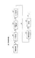
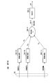
- FIG. 2 shows the overall configuration of the object identification device according to the embodiment of the present invention.
- a person image is mainly identified by the object identification device 100
- the identification target of the object identification device 100 is not limited to a person image.
- the object identification device 100 acquires an image by the image acquisition unit 101.
- the image acquisition unit 101 is, for example, a camera or a scanner.
- the image acquisition unit 101 acquires an image, further cuts out a necessary portion of the acquired image, and performs preprocessing such as image conversion, thereby obtaining grayscale image data S1 and outputs it.
- the noise removing unit 102 removes noise from the grayscale image data S1.
- a noise removal filter may be used as the noise removal unit 102, and a median filter, a sharp filter, an average value filter, or the like may be used as the noise removal filter.
- the grayscale image data S ⁇ b> 2 from which noise has been removed is output to the image size normalization unit 103.
- the image size normalization unit 103 normalizes the size of the grayscale image S2 from which noise has been removed. That is, the image size normalization unit 103 changes the size of the input gray image to a predetermined size. For example, when the input image is smaller than the determined size, the enlargement operation is performed, and when the input image is larger than the determined size, the reduction operation is performed. In the example of the present embodiment, 64 (pixels) ⁇ 128 (pixels) is adopted as the image normalization size, and all images are changed to an image size of 64 (pixels) ⁇ 128 (pixels).
- the size-normalized image data S3 is output to the edge extraction unit 104.
- the edge extraction unit 104 extracts an edge from the grayscale image S3 whose size has been normalized.
- the edge extraction unit 104 obtains edge direction image data S4 by differentiating grayscale image data S3, for example.
- the edge direction image data S4 is output to the feature amount calculation unit 105.
- the feature amount calculation unit 105 calculates a feature amount S5 from the edge direction image data S4 and outputs it to the identification unit 106.
- the identification unit 106 identifies whether the input image (that is, the image acquired by the image acquisition unit 101) is a person image based on the feature amount S5.
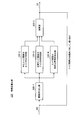
- FIG. 3 shows the configuration of the feature amount calculation unit 105.
- the feature amount calculation unit 105 inputs the edge direction image obtained by the edge extraction unit 104 to the image cutout unit 105-1.
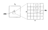
- the image cutout unit 105-1 cuts out images of the predetermined areas AR1 and AR2 from the edge image.
- 4A and 4B show an example in which areas AR1 and AR2 each having 5 (pixels) ⁇ 5 (pixels) are cut out.
- 4A shows an example of an edge pattern that often appears in a person image
- FIG. 4B shows an example of an edge pattern that often appears in a tree image.
- the center pixel P0 of the areas AR1 and AR2 is the reference point of the spatial positional relationship.
- the edge image data in the area AR1 is output to the edge direction determination unit 105-2 of the center edge pixel, the edge direction determination unit 105-3 of the neighboring edge pixel, and the spatial positional relationship detection unit 105-4 of the edge pixel. Is done.
- the edge direction is divided into, for example, six directions.
- Each edge direction 1 to 6 is in the following range.
- Edge direction 1 ° to 30 °, 180 ° to 210 ° Edge direction 2: 30 ° -60 °, 210 ° -240 ° Edge direction 3: 60 ° -90 °, 240 ° -270 ° Edge direction 4: 90 ° to 120 °, 270 ° to 300 ° Edge direction 5: 120 ° to 150 °, 300 ° to 330 ° Edge direction 6: 150 ° to 180 °, 330 ° to 360 °
- the edge direction of a certain edge pixel is obtained by arctan calculation of the luminance difference (gradient) between the pixel and the pixels in the horizontal and vertical directions adjacent to the pixel.
- the edge direction of the pixel is determined as the obtained edge direction.
- the luminance difference is equal to or smaller than the predetermined value, it is determined that the pixel is not an edge image, and the edge direction is set to -1.
- the edge direction determination unit 105-2 of the central edge pixel obtains the edge direction of the central pixel P0 (pixel of coordinates (x, y)) in FIG. 4A and outputs the obtained edge direction to the computing unit 105-5.
- the edge direction determination unit 105-3 of the neighboring edge pixel obtains the edge direction of the edge pixel existing in the neighboring region of the center pixel P0, and outputs the obtained edge direction to the computing unit 105-5.
- the edge direction determination unit 105-3 of the neighboring edge pixels determines the edge direction of each of the four edge pixels.
- the feature quantity calculation unit 105 of the present embodiment detects the spatial positional relationship of the edge pixels by the spatial positional relationship detection unit 105-4 of the edge pixels.
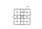
- the spatial position relationship detection unit 105-4 of the edge pixel detects which edge region existing in the neighborhood region of the center pixel P0 is in which of the partition regions obtained by dividing the neighborhood region of the center pixel P0 into a plurality of regions. Detect if it exists.
- FIG. 6 shows an example of the division of the neighboring area. In the example of FIG. 6, the neighboring region is divided into eight regions R 1 to R 8 .
- the edge pixel spatial positional relationship detection unit 105-4 detects in which of the regions R 1 to R 8 each edge pixel is located.
- the calculation unit 105-5 is obtained by the edge direction determination unit 105-2 of the center edge pixel, the edge direction determination unit 105-3 of the neighboring edge pixel, and the spatial positional relationship detection unit 105-4 of the edge pixel.
- a three-dimensional histogram is calculated using the detection result. This three-dimensional histogram can be called an edge space co-occurrence matrix (spatialpatco-occurrence matrix of edge directions). The edge space co-occurrence matrix will be described.
- E i represents the number of edge direction at N i, from the edge image S4 in the given M (pixel) ⁇ N (pixels), an edge direction image E i of a certain number (six in the case of FIG. 4A) Ask.
- E i is defined as follows:
- i is the number in the edge direction of the central pixel P0, which is the reference point of the spatial positional relationship, and the pixels existing in the neighboring region of the central pixel P0 (in the case of FIGS. 4A and 4B, 24 pixels around the central pixel P0).
- the edge direction number of the pixel) is j
- the position number of the pixel existing in the neighboring region of the center pixel P0 is k
- the computing unit 105-5 calculates the edge space co-occurrence matrix H SCO (i , J, k).
- R k in formula (5) shows a division area number.
- the edge spatial co-occurrence matrix H SCO (i, j, k) represented by the equation (5) is the edge direction of the predetermined pixel (center pixel P0) and the edge of the edge pixel existing in the neighboring area of the predetermined pixel.
- the number of edge pixels defined by the direction and the spatial positional relationship between the predetermined pixels and the edge pixels existing in the neighboring area is calculated as the feature amount of the image.
- the edge spatial co-occurrence matrix H SCO (i, j, k) represented by the equation (5) takes into account the positional relationship of the edges with respect to the entire image, so that the conventional edge histogram (HOG) or the conventional Figures that cannot be distinguished by the co-occurrence matrix of edge directions have the ability to be distinguished.
- HOG edge histogram
- the value of H SCO (4, 3, 3 ) is the edge direction 3 (in the upper right direction (position R 3 ) of the pixel in the edge direction 4 (90 ° to 120 °, 270 ° to 300 °). 60 ° to 90 °, 240 ° to 270 °).
- This value (feature value) should be large in the edge pattern that often appears in the tree image shown in FIG. 4B.
- H SCO (4, 3, 3) 2.
- H SCO (4, 3, 3) 0.
- H SCO (4, 3, 6 ) is the edge direction 3 (60 ° to 120 °) in the lower left direction (position R 6 ) of the pixel in the edge direction 4 (90 ° to 120 °, 270 ° to 300 °). 90 °, 240 ° to 270 °).
- the computing unit 105-5 obtains the edge space co-occurrence matrix H SCO (i, j, k) for all combinations of i, j, and k.
- H SCO edge space co-occurrence matrix
- FIG. 7 shows the configuration of the identification unit 106.
- the identification unit 106 includes a plurality of weak classifiers 106-11 to 106-1n, a coupling unit 106-2, and a determination unit 106-3.
- the feature quantity S5 (feature quantity 1 to n) obtained by the feature quantity calculation unit 105 is input to the weak classifiers 106-11 to 106-1n.
- the weak discriminators 106-11 to 106-1n are provided in a number corresponding to the feature amounts 1 to n. In the example of the present embodiment, 288 weak classifiers are provided, but a smaller number may be used.
- the weak classifiers 106-11 to 106-1n have a feature amount acquired by learning in advance and a discrimination function corresponding thereto. Specifically, when a person is to be identified by the object identification device 100, a large amount of human images and non-person images are used as training images during learning, and the output result of the feature amount calculation unit 105 of the object identification device 100 By obtaining S5 and performing learning by a machine learning method, for example, a boosting method, each of the weak classifiers 106-11 to 106-1n acquires an identification function corresponding to each feature amount of the person image.
- the estimated values h 1 to h n are added together by the combining unit 106-2, and the estimated value H obtained thereby is output to the determining unit 106-3.
- the determination unit 106-3 determines the threshold value of the estimated value H. If the estimated value H is larger than the predetermined threshold value, the determination unit 106-3 determines that the input image is a person image and outputs a determination result S6.
- the feature amount calculation unit 105 performs the edge direction determination unit 105-2 of the center edge pixel on all the pixels of the image.
- the edge direction determination unit 105-3 of the neighboring edge pixel and the spatial positional relationship detection unit 105-4 of the edge pixel detect the edge direction and the edge positional relationship of each edge pixel.
- the calculation unit 105-5 of the feature amount calculation unit 105 calculates the edge space co-occurrence matrix as the feature amount S5 by the equation (5).
- corresponding feature quantities that are elements of the edge space co-occurrence matrix are input to the corresponding weak classifiers 106-11 to 106-1n.
- combining section 106-2 calculates estimated value H.
- the determination unit 106-3 determines the estimated value H as a threshold value.
- the determination unit 106-3 moves to step ST17, determines that the input image is a person image, and outputs “1” as the determination result S6.
- the determination unit 106-3 moves to step ST18, determines that the input image is a non-person image, and sets “ ⁇ 1” as the determination result S6. Output.
- step ST17 or step ST18 the feature amount calculation and identification process is ended in step ST19.
- the feature amount calculation unit 105 performs the edge direction of the predetermined pixel (in the case of the embodiment, the central pixel) and the edge pixel existing in the neighboring area of the predetermined pixel.
- the edge position is calculated by calculating, as the image feature quantity S5, the number of edge pixels (three-dimensional histogram) defined by the edge direction of the image and the spatial positional relationship between the edge pixels existing in the neighboring area of the predetermined pixel.
- a feature quantity S5 that also expresses the relationship can be obtained.
- edge space co-occurrence matrix (feature amount) calculated in the present embodiment is a global feature, it is possible to obtain a feature amount that is robust to positional deviation and posture change for a person in the image.
- the spatial positional relationship between the edge direction of the predetermined pixel, the edge direction of the edge pixel existing in the neighboring area of the predetermined pixel, and the edge pixel existing in the neighboring area of the predetermined pixel As described above, the number of edge pixels (three-dimensional histogram) defined by the above is calculated as the image feature amount. For example, the edge direction of the predetermined pixel and the edge pixel existing in the neighboring area of the predetermined pixel The number of edge pixels defined by the spatial positional relationship (two-dimensional histogram) may be calculated as the image feature amount.
- the configuration of the feature quantity calculation unit 105 is a configuration in which the edge direction determination unit 105-3 of the neighboring edge pixel is omitted from the configuration of FIG. 3, and the calculation unit 105-5 has an edge space co-occurrence matrix according to the following equation: What is necessary is just to obtain H 1 (i, k).
- the identification accuracy is considered to be lower than that in the above-described embodiment, but a feature amount expressing the positional relationship of edges can be obtained as in the above-described embodiment.
- the difference in edge pattern due to the difference in edge positional relationship can be identified.
- the number of edge pixels (two-dimensional histogram) defined by the edge direction of the edge pixel existing in the neighboring area of the predetermined pixel and the spatial positional relationship between the edge pixels existing in the neighboring area of the predetermined pixel is expressed as the image. You may calculate as a feature-value.
- the configuration of the feature quantity calculation unit 105 is configured such that the edge direction determination unit 105-2 of the central edge pixel is omitted from the configuration of FIG. 3, and the calculation unit 105-5 uses the following equation to calculate the edge space matrix H 2. What is necessary is just to obtain (j, k).
- the identification unit 106 has a plurality of weak classifiers 106-11 to 106-1n has been described.
- the configuration of the identification unit 106 is not limited to this. Since the present invention is particularly characterized in the feature amount calculation processing by the feature amount calculation unit 105, other configurations may be changed as appropriate.
- the present invention has an effect of identifying a difference in edge pattern due to a difference in edge positional relationship, and is suitable for identifying a person image, for example.
Landscapes
- Engineering & Computer Science (AREA)
- Computer Vision & Pattern Recognition (AREA)
- Physics & Mathematics (AREA)
- General Physics & Mathematics (AREA)
- Theoretical Computer Science (AREA)
- Multimedia (AREA)
- Image Analysis (AREA)
Abstract
特徴量算出部(105)は、所定画素のエッジの方向と、前記所定画素の近隣領域に存在するエッジ画素のエッジ方向と、前記所定画素の近隣領域に存在するエッジ画素との空間位置関係と、によって規定したエッジ画素の個数(3次元ヒストグラム)を画像の特徴量S5として算出する。これにより、エッジの位置関係をも表現した特徴量(S5)を得ることができる。この結果、エッジの位置関係の違いに起因するエッジパターンの違いをも識別し得、例えば人物画像の識別精度を向上できる。
Description
本発明は、特徴量抽出装置、物体識別装置及び特徴量抽出方法に関し、例えば、与えられた濃淡画像が人物であるか否かを判断する技術に関する。
従来、与えられた画像が人物画像であるか否かを判定する場合、エッジ特徴を用いることが多い。例えば、エッジ方向ヒストグラム(HOG:Histograms of Oriented Gradients)を用いた物体識別方法が提案されている(例えば、特許文献1~3参照)。
エッジ方向ヒストグラムを用いた物体識別方法について、簡単に説明する。エッジ方向の数をNiで表し、与えられたM(画素)×N(画素)の濃淡画像Iから、ある個数のエッジ方向画像Eiを求める。ここで、Eiを次式のように定義する。

エッジ方向ヒストグラム(HOG)は、次式によって求められる。

エッジ方向ヒストグラムを用いることにより、図1Aのエッジ画像と図1Bのエッジ画像とを識別することができる。つまり、エッジ方向ヒストグラムを用いることにより、エッジ方向の異なる画像を識別することができるようになる。
しかしながら、エッジ方向ヒストグラムを用いた識別方法は、画像全体の統計的な特徴を検出するので、例えば図1Bと図1Cとを識別することは困難である。何故なら、図1Bのエッジ画像と図1Cのエッジ画像との間では、エッジ方向の度数は同一であるからである。この結果、誤認識が生じる。
そこで、図1Bのエッジ画像と図1Cのエッジ画像とを識別できる一つの方法として、エッジの共起性を用いたものが提案されている(例えば非特許文献1参照)。この方法は、エッジの共起性を示す特徴量として、エッジ方向の共起行列(co-occurrence matrix of edge direction)を用いる。エッジ方向の共起行列HCO(i,j)は、次式で表される。

エッジ方向の共起性を用いた画像識別方法では、近隣領域中のエッジ方向を考慮した識別を行うので、エッジ方向ヒストグラムのようにエッジ方向の度数のみを用いた識別では正しく識別できなかったエッジも、正しく識別できるようになる。
Sami Brand, Jorma Laaksonen, Erkki Oja, "Statistical Shape Features in Content-Based Image Retrieval", Proceedings of the 15th International Conference on Pattern Recognition(ICPR’2000), Volume 2, pp. 6062
しかしながら、非特許文献1のような従来のエッジ方向の共起行列を用いた画像識別方法においては、エッジの位置関係が十分に配慮されていないので、物体を誤認識するおそれがある。従来のエッジ方向の共起行列を用いた画像識別方法では、例えば、図1Cと図1Dとの識別が困難である。因みに、図1Dのようなエッジパターンは、人物画像の「肘」によく出るパターンであり、図1Cのようなエッジパターンは、「木」によく出るエッジパターンである。よって、例えば歩行者を識別しようとする場合に、「木」の画像を誤って歩行者の画像であると誤認識する可能性があり、不十分であった。
本発明の目的は、エッジの位置関係の違いに起因するエッジパターンの違いをも識別し得、例えば人物画像の識別精度を向上し得る特徴量抽出装置、物体識別装置及び特徴量抽出方法を提供することである。
本発明の特徴量抽出装置の一つの態様は、所定画素のエッジの方向及び又は前記所定画素の近隣領域に存在するエッジ画素のエッジ方向と、前記所定画素と前記近隣領域に存在するエッジ画素との空間位置関係と、によって規定したエッジ画素の個数を、画像の特徴量として算出する特徴量算出部と、を具備する構成を採る。
本発明の物体識別装置の一つの態様は、前記特徴量抽出装置と、前記特徴量抽出装置によって得られた複数の特徴量をそれぞれ入力し、入力した特徴量と予め学習によって獲得された識別関数とから推定値を出力する複数の弱識別器と、前記複数の弱識別器から出力された推定値を足し合わせる結合部と、足し合わされた推定値を閾値判定する判定部と、を具備する構成を採る。
本発明の特徴量抽出方法の一つの態様は、濃淡画像からエッジ画像を形成するエッジ画像形成ステップと、所定画素のエッジの方向及び又は前記所定画素の近隣領域に存在するエッジ画素のエッジ方向と、前記所定画素の近隣領域に存在するエッジ画素との空間位置関係と、によって規定したエッジ画素の個数を、画像の特徴量として算出する特徴量算出ステップと、を含む。
本発明によれば、エッジの位置関係の違いに起因するエッジパターンの違いをも識別し得、例えば人物画像の識別精度を向上し得る。
以下、本発明の実施の形態について図面を参照して詳細に説明する。
[全体構成]
図2に、本発明の実施の形態に係る物体識別装置の全体構成を示す。本実施の形態では、物体識別装置100によって、主に、人物画像を識別する場合について説明するが、物体識別装置100の識別対象は人物画像に限らない。
図2に、本発明の実施の形態に係る物体識別装置の全体構成を示す。本実施の形態では、物体識別装置100によって、主に、人物画像を識別する場合について説明するが、物体識別装置100の識別対象は人物画像に限らない。
物体識別装置100は、画像取得部101によって画像を取得する。画像取得部101は、例えばカメラやスキャナである。画像取得部101は、画像を取得し、さらに取得した画像に対して必要な部分を切り出したり、画像変換といった前処理を施すことにより、濃淡画像データS1を得、これを出力する。
ノイズ除去部102は、濃淡画像データS1のノイズを除去する。実際上、ノイズ除去部102としてはノイズ除去フィルタを用いればよく、ノイズ除去フィルタとしてはメディアンフィルタ、シャープフィルタ又は平均値フィルタ等を用いればよい。ノイズが除去された濃淡画像データS2は、画像サイズ正規化部103に出力される。
画像サイズ正規化部103は、ノイズが除去された濃淡画像S2をサイズ正規化する。すなわち、画像サイズ正規化部103は、入力された濃淡画像を、予め決めたサイズにサイズ変更する。例えば、入力された画像が決られたサイズよりも小さい場合には拡大操作し、入力された画像が決められたサイズよりも大きい場合には縮小操作する。本実施の形態の例では、画像正規化のサイズとして64(画素)×128(画素)を採用し、全ての画像を64(画素)×128(画素)の画像サイズに変更する。サイズ正規化された画像データS3は、エッジ抽出部104に出力される。
エッジ抽出部104は、サイズ正規化された濃淡画像S3からエッジを抽出する。エッジ抽出部104は、例えば濃淡画像データS3を微分することで、エッジ方向画像データS4を得る。エッジ方向画像データS4は、特徴量算出部105に出力される。
特徴量算出部105は、エッジ方向画像データS4から特徴量S5を算出し、これを識別部106に出力する。識別部106は、特徴量S5に基づいて、入力画像(すなわち画像取得部101によって取得された画像)が人物画像であるか否かを識別する。
[特徴量算出部]
図3に、特徴量算出部105の構成を示す。特徴量算出部105は、エッジ抽出部104で得たエッジ方向画像を画像切り出し部105-1に入力する。画像切り出し部105-1は、図4A、図4Bに示すように、エッジ画像から所定領域AR1、AR2の画像を切り出す。図4A、図4Bは、5(画素)×5(画素)からなる領域AR1、AR2が切り出された例を示す。なお、図4Aは人物画像によく出るエッジパターンの例を示し、図4Bは木の画像によく出るエッジパターンの例を示す。ここで、領域AR1、AR2の中心画素P0が空間位置関係の基準点である。
図3に、特徴量算出部105の構成を示す。特徴量算出部105は、エッジ抽出部104で得たエッジ方向画像を画像切り出し部105-1に入力する。画像切り出し部105-1は、図4A、図4Bに示すように、エッジ画像から所定領域AR1、AR2の画像を切り出す。図4A、図4Bは、5(画素)×5(画素)からなる領域AR1、AR2が切り出された例を示す。なお、図4Aは人物画像によく出るエッジパターンの例を示し、図4Bは木の画像によく出るエッジパターンの例を示す。ここで、領域AR1、AR2の中心画素P0が空間位置関係の基準点である。
以下、図4Aの領域AR1が切り出された場合を例に説明する。領域AR1内のエッジ画像データは、中心エッジ画素のエッジ方向判定部105-2と、近隣エッジ画素のエッジ方向判定部105-3と、エッジ画素の空間位置関係検出部105-4と、に出力される。
ここで、本実施の形態では、図5に示すように、エッジ方向を例えば6方向に分ける。各エッジ方向1~6は、以下の範囲である。
エッジ方向1:0°~30°,180°~210°
エッジ方向2:30°~60°,210°~240°
エッジ方向3:60°~90°,240°~270°
エッジ方向4:90°~120°,270°~300°
エッジ方向5:120°~150°,300°~330°
エッジ方向6:150°~180°,330°~360°
エッジ方向2:30°~60°,210°~240°
エッジ方向3:60°~90°,240°~270°
エッジ方向4:90°~120°,270°~300°
エッジ方向5:120°~150°,300°~330°
エッジ方向6:150°~180°,330°~360°
なお、あるエッジ画素におけるエッジ方向は、当該画素と、当該画素に隣接する横と縦方向の画素との輝度の差分(勾配)のarctan演算で求められる。前記輝度の差分が所定値より大きい場合、当該画素のエッジ方向を得られたエッジ方向とし、所定値以下の場合、当該画素がエッジ画像でないと判定し、エッジ方向を-1とする。
中心エッジ画素のエッジ方向判定部105-2は、図4Aの中心画素P0(座標(x、y)の画素)のエッジ方向を求め、求めたエッジ方向を演算部105-5に出力する。
近隣エッジ画素のエッジ方向判定部105-3は、中心画素P0の近隣領域に存在するエッジ画素のエッジ方向を求め、求めたエッジ方向を演算部105-5に出力する。図4Aの場合には、中心画素P0の近隣領域に4つのエッジ画素が存在するので、近隣エッジ画素のエッジ方向判定部105-3は、この4つのエッジ画素それぞれのエッジ方向を判定する。
これに加えて、本実施の形態の特徴量算出部105は、エッジ画素の空間位置関係検出部105-4によって、エッジ画素の空間位置関係を検出する。エッジ画素の空間位置関係検出部105-4は、中心画素P0の近隣領域に存在するエッジ画素が、中心画素P0の近隣領域を複数の領域に分割してなる分割領域のうちのどの分割領域に存在するかを検出する。図6に、近隣領域の分割の例を示す。図6の例では、近隣領域が8個の領域R1~R8に分割されている。エッジ画素の空間位置関係検出部105-4は、各エッジ画素が領域R1~R8のうちのどの領域に位置するかを検出する。
演算部105-5は、中心エッジ画素のエッジ方向判定部105-2と、近隣エッジ画素のエッジ方向判定部105-3と、エッジ画素の空間位置関係検出部105-4と、によって得られた検出結果を用いて、3次元のヒストグラムを算出する。この3次元のヒストグラムは、エッジ空間共起マトリクス(spatial co-occurrence matrix of edge directions)と呼ぶことができる。このエッジ空間共起マトリクスについて説明する。
ここで、エッジ方向の数をNiで表し、与えられたM(画素)×N(画素)のエッジ画像S4から、ある個数(図4Aの場合には6個)のエッジ方向画像Eiを求める。ここで、Eiを、次式のように定義する。

ここで、空間位置関係の基準点である中心画素P0のエッジ方向の番号をiとし、中心画素P0の近隣領域に存在する画素(図4A、図4Bの場合、中心画素P0の周囲の24個の画素)のエッジ方向の番号をjとし、中心画素P0の近隣領域に存在する画素の位置番号をkとすると、演算部105-5は、次式によって、エッジ空間共起マトリクスHSCO(i,j,k)を求める。

なお、式(5)におけるRkは、図6に示すように、分割領域番号を示す。
式(5)で表されるエッジの空間共起マトリクスHSCO(i,j,k)は、所定画素(中心画素P0)のエッジの方向と、所定画素の近隣領域に存在するエッジ画素のエッジ方向と、所定画素と近隣領域に存在するエッジ画素との空間位置関係と、によって規定したエッジ画素の個数を、画像の特徴量として算出したものである。式(5)で表されるエッジの空間共起マトリクスHSCO(i,j,k)は、画像全体に対し、エッジの位置関係が考慮されているので、従来のエッジヒストグラム(HOG)や従来のエッジ共起マトリクス(co-occurrence matrix of edge directions)によっては区別できない図形も、区別できる能力がある。
ここで、例えば、HSCO(4,3,3)の値は、エッジ方向4(90°~120°,270°~300°)の画素の右上方向(位置R3)にあるエッジ方向3(60°~90°,240°~270°)の画素の数である。図4Bに示した、木の画像によく出るエッジパターンにおいては、この値(特徴量)が大きいはずである。具体的には、図4Bのエッジパターンの場合には、HSCO(4,3,3)=2となる。これに対して、図4Aのエッジパターンの場合には、HSCO(4,3,3)=0となる。
また、HSCO(4,3,6)の値は、エッジ方向4(90°~120°,270°~300°)の画素の左下方向(位置R6)にあるエッジ方向3(60°~90°,240°~270°)の画素の数である。図4Aに示した、人物の画像によく出るエッジパターンにおいては、この値(特徴量)が大きいはずである。具体的には、図4Aのエッジパターンの場合には、HSCO(4,3,6)=2となる。これに対して、図4Bの場合には、エッジパターンの場合には、HSCO(4,3,6)=0となる。
このようにして、エッジ画像の全画素に対し、演算部105-5は、i,j,kの全ての組み合わせについて、エッジ空間共起マトリクスHSCO(i,j,k)を求める。本実施の形態の例では、i=1,2,………,6であり、j=1,2,………,6であり、k=1,2,………,8であるので、6×6×8=288個の要素からなるエッジ空間共起マトリクスが得られる。すなわち、特徴量S5として、288個の特徴量(3次元ヒストグラム)が得られる。
[識別部]
図7に、識別部106の構成を示す。識別部106は、複数の弱識別器106-11~106-1nと、結合部106-2と、判定部106-3とを有する。
図7に、識別部106の構成を示す。識別部106は、複数の弱識別器106-11~106-1nと、結合部106-2と、判定部106-3とを有する。
弱識別器106-11~106-1nには、特徴量算出部105によって得られた特徴量S5(特徴量1~n)が入力される。弱識別器106-11~106-1nは、特徴量1~nに対応した数だけ設けられている。本実施の形態の例では、288個の弱識別器が設けられているが、これより少ない数でも構わない。
弱識別器106-11~106-1nは、予め学習によって獲得された特徴量及びそれに対応する識別関数を有する。具体的には、物体識別装置100によって人物を識別しようとする場合には、学習時に、トレーニング画像として大量の人物画像と非人物画像を用い、物体識別装置100の特徴量算出部105の出力結果S5を求め、機械学習手法、例えば、ブースティング手法により学習を行うことにより、各弱識別器106-11~106-1nが人物画像の各特徴量に対応した識別関数を獲得する。
そして、実際の画像識別時には、特徴量算出部105から入力される特徴量1~nと、予め学習によって獲得されている上記識別関数とを用いて、各特徴量に対応する人物である推定値h1~hnが出力される。
各推定値h1~hnは、結合部106-2によって足し合わされ、これにより得られた推定値Hが判定部106-3に出力される。判定部106-3は、推定値Hを閾値判定し、推定値Hが所定の閾値よりも大きい場合には、入力画像が人物画像であると判定し、判定結果S6を出力する。
[動作]
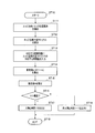
次に、図8を用いて、物体識別装置100における動作について説明する。ここでは、特に本発明の特徴である、特徴量算出部105及び識別部106の動作について説明する。
次に、図8を用いて、物体識別装置100における動作について説明する。ここでは、特に本発明の特徴である、特徴量算出部105及び識別部106の動作について説明する。
物体識別装置100は、ステップST10で、特徴量算出及び識別処理を開始すると、ステップST11で、特徴量算出部105における、画像の全画素に対し、中心エッジ画素のエッジ方向判定部105-2、近隣エッジ画素のエッジ方向判定部105-3及びエッジ画素の空間位置関係検出部105-4が、各エッジ画素のエッジ方向とエッジ位置関係を検出する。
続くステップST12では、特徴量算出部105の演算部105-5が、式(5)によってエッジ空間共起マトリクスを特徴量S5として算出する。
続くステップST13では、対応する弱識別器106-11~106-1nに、エッジ空間共起マトリクスの要素である対応する特徴量(特徴量1~n)を入力する。
続くステップST14では、各弱識別器106-11~106-1nが推定値hi(i=1~n)を算出する。続くステップST15では、結合部106-2が推定値Hを算出する。
続くステップST16では、判定部106-3が推定値Hを閾値判定する。推定値Hが閾値よりも大きい場合には、判定部106-3は、ステップST17に移って、入力画像が人物画像であると判断し、判定結果S6として「1」を出力する。これに対して、推定値Hが閾値以下の場合には、判定部106-3は、ステップST18に移って、入力画像が非人物画像であると判断し、判定結果S6として「-1」を出力する。
ステップST17又はステップST18の後、ステップST19にて、特徴量算出及び識別処理が終了される。
[効果]
以上説明したように、本実施の形態によれば、特徴量算出部105が、所定画素(実施の形態の場合、中心画素)のエッジの方向と、前記所定画素の近隣領域に存在するエッジ画素のエッジ方向と、前記所定画素の近隣領域に存在するエッジ画素との空間位置関係と、によって規定したエッジ画素の個数(3次元ヒストグラム)を画像の特徴量S5として算出したことにより、エッジの位置関係をも表現した特徴量S5を得ることができる。この結果、エッジの位置関係の違いに起因するエッジパターンの違いをも識別し得、例えば人物画像の識別精度を向上できるようになる。
以上説明したように、本実施の形態によれば、特徴量算出部105が、所定画素(実施の形態の場合、中心画素)のエッジの方向と、前記所定画素の近隣領域に存在するエッジ画素のエッジ方向と、前記所定画素の近隣領域に存在するエッジ画素との空間位置関係と、によって規定したエッジ画素の個数(3次元ヒストグラム)を画像の特徴量S5として算出したことにより、エッジの位置関係をも表現した特徴量S5を得ることができる。この結果、エッジの位置関係の違いに起因するエッジパターンの違いをも識別し得、例えば人物画像の識別精度を向上できるようになる。
また、本実施の形態で算出するエッジ空間共起マトリクス(特徴量)は、グローバルな特徴であるので、画像中の人物に位置ずれや姿勢変動にロバスト性のある特徴量を得ることができる。
[他の実施の形態]
なお、上述の実施の形態では、所定画素のエッジの方向と、前記所定画素の近隣領域に存在するエッジ画素のエッジ方向と、前記所定画素の近隣領域に存在するエッジ画素との空間位置関係と、によって規定したエッジ画素の個数(3次元ヒストグラム)を画像の特徴量として算出した場合について述べたが、例えば、所定画素のエッジの方向と、前記所定画素の近隣領域に存在するエッジ画素との空間位置関係と、によって規定したエッジ画素の個数(2次元ヒストグラム)を画像の特徴量として算出してもよい。
なお、上述の実施の形態では、所定画素のエッジの方向と、前記所定画素の近隣領域に存在するエッジ画素のエッジ方向と、前記所定画素の近隣領域に存在するエッジ画素との空間位置関係と、によって規定したエッジ画素の個数(3次元ヒストグラム)を画像の特徴量として算出した場合について述べたが、例えば、所定画素のエッジの方向と、前記所定画素の近隣領域に存在するエッジ画素との空間位置関係と、によって規定したエッジ画素の個数(2次元ヒストグラム)を画像の特徴量として算出してもよい。
この場合、特徴量算出部105の構成を、図3の構成から近隣エッジ画素のエッジ方向判定部105-3を省略した構成とすると共に、演算部105-5が次式によりエッジ空間共起マトリクスH1(i,k)を求めればよい。

また、所定画素の近隣領域に存在するエッジ画素のエッジ方向と、前記所定画素の近隣領域に存在するエッジ画素との空間位置関係と、によって規定したエッジ画素の個数(2次元ヒストグラム)を画像の特徴量として算出してもよい。
この場合、特徴量算出部105の構成を、図3の構成から中心エッジ画素のエッジ方向判定部105-2を省略した構成とすると共に、演算部105-5が次式によりエッジ空間マトリクスH2(j,k)を求めればよい。

2008年11月11日出願の特願2008-288864の日本出願に含まれる明細書、図面及び要約書の開示内容は、すべて本願に援用される。
本発明は、エッジの位置関係の違いに起因するエッジパターンの違いをも識別できる効果を有し、例えば人物画像を識別するのに好適である。
Claims (6)
- 濃淡画像からエッジ画像を形成するエッジ画像抽出部と
所定画素のエッジの方向及び又は前記所定画素の近隣領域に存在するエッジ画素のエッジ方向と、前記所定画素と前記近隣領域に存在するエッジ画素との空間位置関係と、によって規定したエッジ画素の個数を、画像の特徴量として算出する特徴量算出部と、
を具備する特徴量抽出装置。 - 前記空間位置関係は、前記近隣領域に存在するエッジ画素が、前記所定画素の近隣領域を複数の領域に分割してなる分割領域のうちのどの分割領域に存在するかである、
請求項1に記載の特徴量抽出装置。 - 濃淡画像からエッジ画像を形成するエッジ画像抽出部と
前記エッジ画像の特徴量を、次の式(1)又は式(2)によって算出する特徴量算出部と、
を具備する特徴量抽出装置。


- 濃淡画像からエッジ画像を形成するエッジ画像抽出部と
前記エッジ画像の特徴量を、次の式(4)によって算出する特徴量算出部と、
を具備する特徴量抽出装置。


- 請求項1に記載の特徴量抽出装置と、
前記特徴量抽出装置によって得られた複数の特徴量をそれぞれ入力し、入力した特徴量と予め学習によって獲得された識別関数とから推定値を出力する複数の弱識別器と、
前記複数の弱識別器から出力された推定値を足し合わせる結合部と、
足し合わされた推定値を閾値判定する判定部と、
を具備する物体識別装置。 - 濃淡画像からエッジ画像を形成するエッジ画像形成ステップと、
所定画素のエッジの方向及び又は前記所定画素の近隣領域に存在するエッジ画素のエッジ方向と、前記所定画素の近隣領域に存在するエッジ画素との空間位置関係と、によって規定したエッジ画素の個数を、画像の特徴量として算出する特徴量算出ステップと、
を含む特徴量抽出方法。
Priority Applications (3)
| Application Number | Priority Date | Filing Date | Title |
|---|---|---|---|
| CN200980144589.XA CN102209974B (zh) | 2008-11-11 | 2009-11-06 | 特征量提取装置、物体识别装置、以及特征量提取方法 |
| US13/128,473 US8649608B2 (en) | 2008-11-11 | 2009-11-06 | Feature value extracting device, object identification device, and feature value extracting method |
| EP09825883.3A EP2348485A4 (en) | 2008-11-11 | 2009-11-06 | Feature value extracting device, object identification device, and feature value extracting method |
Applications Claiming Priority (2)
| Application Number | Priority Date | Filing Date | Title |
|---|---|---|---|
| JP2008-288864 | 2008-11-11 | ||
| JP2008288864A JP5376906B2 (ja) | 2008-11-11 | 2008-11-11 | 特徴量抽出装置、物体識別装置及び特徴量抽出方法 |
Publications (1)
| Publication Number | Publication Date |
|---|---|
| WO2010055629A1 true WO2010055629A1 (ja) | 2010-05-20 |
Family
ID=42169775
Family Applications (1)
| Application Number | Title | Priority Date | Filing Date |
|---|---|---|---|
| PCT/JP2009/005920 WO2010055629A1 (ja) | 2008-11-11 | 2009-11-06 | 特徴量抽出装置、物体識別装置及び特徴量抽出方法 |
Country Status (5)
| Country | Link |
|---|---|
| US (1) | US8649608B2 (ja) |
| EP (1) | EP2348485A4 (ja) |
| JP (1) | JP5376906B2 (ja) |
| CN (1) | CN102209974B (ja) |
| WO (1) | WO2010055629A1 (ja) |
Families Citing this family (15)
| Publication number | Priority date | Publication date | Assignee | Title |
|---|---|---|---|---|
| JP5707570B2 (ja) * | 2010-03-16 | 2015-04-30 | パナソニックIpマネジメント株式会社 | 物体識別装置、物体識別方法、及び、物体識別装置の学習方法 |
| CN102414720B (zh) | 2010-03-19 | 2015-08-19 | 松下电器(美国)知识产权公司 | 特征量计算装置、特征量计算方法 |
| JP5706647B2 (ja) | 2010-09-03 | 2015-04-22 | キヤノン株式会社 | 情報処理装置、およびその処理方法 |
| SE535888C2 (sv) * | 2011-06-08 | 2013-02-05 | Imtt Svenska Ab | Förfarande för att identifiera en karaktäristisk del i en bild |
| EP2574958B1 (en) | 2011-09-28 | 2017-02-22 | Honda Research Institute Europe GmbH | Road-terrain detection method and system for driver assistance systems |
| WO2013102900A1 (en) * | 2012-01-04 | 2013-07-11 | Mike Goldstein | Inspection device for mechanical instruments and uses thereof |
| US9152888B2 (en) * | 2012-09-13 | 2015-10-06 | Los Alamos National Security, Llc | System and method for automated object detection in an image |
| US9092692B2 (en) | 2012-09-13 | 2015-07-28 | Los Alamos National Security, Llc | Object detection approach using generative sparse, hierarchical networks with top-down and lateral connections for combining texture/color detection and shape/contour detection |
| US9152881B2 (en) | 2012-09-13 | 2015-10-06 | Los Alamos National Security, Llc | Image fusion using sparse overcomplete feature dictionaries |
| JP5957357B2 (ja) * | 2012-10-15 | 2016-07-27 | 株式会社日立ハイテクノロジーズ | パターン検査・計測装置及びプログラム |
| KR102056686B1 (ko) | 2013-02-18 | 2019-12-18 | 삼성디스플레이 주식회사 | 영상 처리부, 이를 포함하는 표시 장치 및 이를 이용한 영상 처리 방법 |
| US9767571B2 (en) | 2013-07-29 | 2017-09-19 | Samsung Electronics Co., Ltd. | Apparatus and method for analyzing image including event information |
| CN112017203A (zh) * | 2019-05-31 | 2020-12-01 | 广州市百果园信息技术有限公司 | 图像处理方法、视频处理方法、装置、设备及存储介质 |
| CN110929708A (zh) * | 2019-09-30 | 2020-03-27 | 京东数字科技控股有限公司 | 识别泰国身份证中国旗的方法、设备及存储介质 |
| CN114782711B (zh) * | 2022-06-20 | 2022-09-16 | 四川航天职业技术学院(四川航天高级技工学校) | 一种基于图像识别的智能化风险检测方法及系统 |
Citations (8)
| Publication number | Priority date | Publication date | Assignee | Title |
|---|---|---|---|---|
| JPH05210739A (ja) | 1991-09-12 | 1993-08-20 | Fuji Photo Film Co Ltd | 被写体認識方法 |
| JP2003263638A (ja) | 2002-03-08 | 2003-09-19 | Mitsubishi Heavy Ind Ltd | 物体認識装置及び物体認識方法並びに物体認識プログラム |
| JP2006127159A (ja) * | 2004-10-28 | 2006-05-18 | Canon Inc | 画像処理装置、画像処理方法、コンピュータプログラム及び記憶媒体 |
| JP2007156626A (ja) | 2005-12-01 | 2007-06-21 | Nissan Motor Co Ltd | 物体種別判定装置及び物体種別判定方法 |
| JP2008026974A (ja) * | 2006-07-18 | 2008-02-07 | Mitsubishi Electric Corp | 人物追跡装置 |
| JP2008257649A (ja) * | 2007-04-09 | 2008-10-23 | Denso Corp | 画像認識装置 |
| JP2008269181A (ja) * | 2007-04-18 | 2008-11-06 | Matsushita Electric Works Ltd | 対象物検出装置 |
| JP2008288864A (ja) | 2007-05-17 | 2008-11-27 | Casio Comput Co Ltd | 撮像装置、プログラム、編集システム及び編集方法 |
Family Cites Families (7)
| Publication number | Priority date | Publication date | Assignee | Title |
|---|---|---|---|---|
| JP2008004123A (ja) | 1995-09-13 | 2008-01-10 | Fujifilm Corp | 特定形状領域の抽出装置及び方法、特定領域の抽出装置及び方法、複写条件決定装置及び方法 |
| US6381365B2 (en) | 1997-08-22 | 2002-04-30 | Minolta Co., Ltd. | Image data processing apparatus and image data processing method |
| JP3718967B2 (ja) * | 1997-08-22 | 2005-11-24 | コニカミノルタビジネステクノロジーズ株式会社 | 画像特徴量抽出装置および方法並びに画像特徴量抽出プログラムを記録した記録媒体 |
| JP2001175868A (ja) | 1999-12-22 | 2001-06-29 | Nec Corp | 人物検出方法及び装置 |
| JP3661635B2 (ja) * | 2000-11-29 | 2005-06-15 | オムロン株式会社 | 画像処理方法およびその装置 |
| US8015132B2 (en) * | 2008-05-16 | 2011-09-06 | Samsung Electronics Co., Ltd. | System and method for object detection and classification with multiple threshold adaptive boosting |
| JP5210739B2 (ja) | 2008-07-09 | 2013-06-12 | 陞達科技股▲ふん▼有限公司 | 共振回路の周波数を利用してファンの回転速度を設定する方法 |
-
2008
- 2008-11-11 JP JP2008288864A patent/JP5376906B2/ja active Active
-
2009
- 2009-11-06 CN CN200980144589.XA patent/CN102209974B/zh active Active
- 2009-11-06 EP EP09825883.3A patent/EP2348485A4/en not_active Withdrawn
- 2009-11-06 WO PCT/JP2009/005920 patent/WO2010055629A1/ja active Application Filing
- 2009-11-06 US US13/128,473 patent/US8649608B2/en active Active
Patent Citations (8)
| Publication number | Priority date | Publication date | Assignee | Title |
|---|---|---|---|---|
| JPH05210739A (ja) | 1991-09-12 | 1993-08-20 | Fuji Photo Film Co Ltd | 被写体認識方法 |
| JP2003263638A (ja) | 2002-03-08 | 2003-09-19 | Mitsubishi Heavy Ind Ltd | 物体認識装置及び物体認識方法並びに物体認識プログラム |
| JP2006127159A (ja) * | 2004-10-28 | 2006-05-18 | Canon Inc | 画像処理装置、画像処理方法、コンピュータプログラム及び記憶媒体 |
| JP2007156626A (ja) | 2005-12-01 | 2007-06-21 | Nissan Motor Co Ltd | 物体種別判定装置及び物体種別判定方法 |
| JP2008026974A (ja) * | 2006-07-18 | 2008-02-07 | Mitsubishi Electric Corp | 人物追跡装置 |
| JP2008257649A (ja) * | 2007-04-09 | 2008-10-23 | Denso Corp | 画像認識装置 |
| JP2008269181A (ja) * | 2007-04-18 | 2008-11-06 | Matsushita Electric Works Ltd | 対象物検出装置 |
| JP2008288864A (ja) | 2007-05-17 | 2008-11-27 | Casio Comput Co Ltd | 撮像装置、プログラム、編集システム及び編集方法 |
Non-Patent Citations (2)
| Title |
|---|
| SAMI BRAND, JORMA LAAKSONEN, ERKKI OJA: "Statistical Shape Features in Content-Based Image Retrieval", PROCEEDINGS OF THE 15TH INTERNATIONAL CONFERENCE ON PATTERN RECOGNITION, vol. 2, 2000, pages 6062 |
| See also references of EP2348485A4 |
Also Published As
| Publication number | Publication date |
|---|---|
| JP2010117772A (ja) | 2010-05-27 |
| JP5376906B2 (ja) | 2013-12-25 |
| US8649608B2 (en) | 2014-02-11 |
| EP2348485A4 (en) | 2018-01-17 |
| EP2348485A1 (en) | 2011-07-27 |
| CN102209974A (zh) | 2011-10-05 |
| US20110243434A1 (en) | 2011-10-06 |
| CN102209974B (zh) | 2014-05-14 |
Similar Documents
| Publication | Publication Date | Title |
|---|---|---|
| JP5376906B2 (ja) | 特徴量抽出装置、物体識別装置及び特徴量抽出方法 | |
| JP4970381B2 (ja) | 特徴抽出装置、特徴抽出方法、画像処理装置、及び、プログラム | |
| US9224070B1 (en) | System for three-dimensional object recognition and foreground extraction | |
| WO2018081929A1 (zh) | 一种高光谱遥感图像特征提取和分类方法及其系统 | |
| KR101932009B1 (ko) | 다중 객체 검출을 위한 영상 처리 장치 및 방법 | |
| JP4699298B2 (ja) | 人体領域抽出方法および装置並びにプログラム | |
| JP2011053953A (ja) | 画像処理装置及びプログラム | |
| US20170309024A1 (en) | Image processing device, image processing method, and computer-readable recording medium | |
| WO2016059643A1 (en) | System and method for pedestrian detection | |
| Michail et al. | Detection of centroblasts in h&e stained images of follicular lymphoma | |
| Sambyal et al. | Feature based text extraction system using connected component method | |
| Cho et al. | A reliable skin mole localization scheme | |
| JP2016053763A (ja) | 画像処理装置、画像処理方法及びプログラム | |
| US9569681B2 (en) | Methods and systems for efficient image cropping and analysis | |
| JP2016115084A (ja) | 対象物検出装置及びプログラム | |
| JP2010225107A (ja) | 特徴を抽出する装置、方法およびプログラム | |
| JP6364189B2 (ja) | 歩行者検出方法 | |
| Gim et al. | A novel framework for white blood cell segmentation based on stepwise rules and morphological features | |
| WO2013154062A1 (ja) | 画像識別システム、画像識別方法、およびプログラム | |
| JP2011170554A (ja) | 物体認識装置、物体認識方法及び物体認識プログラム | |
| Rabbani et al. | Person identification using SURF features of dental radiograph | |
| JP2004145592A (ja) | 移動ベクトル抽出装置及び方法及びプログラム及びその記録媒体 | |
| Soumya et al. | Text extraction from images: a survey | |
| JP2011159097A (ja) | オブジェクト検出方法及びオブジェクト検出装置 | |
| Wahab et al. | Principal Component Analysis combined with second order statistical feature method for Malaria Parasites classification |
Legal Events
| Date | Code | Title | Description |
|---|---|---|---|
| WWE | Wipo information: entry into national phase |
Ref document number: 200980144589.X Country of ref document: CN |
|
| 121 | Ep: the epo has been informed by wipo that ep was designated in this application |
Ref document number: 09825883 Country of ref document: EP Kind code of ref document: A1 |
|
| WWE | Wipo information: entry into national phase |
Ref document number: 13128473 Country of ref document: US |
|
| NENP | Non-entry into the national phase |
Ref country code: DE |
|
| WWE | Wipo information: entry into national phase |
Ref document number: 2009825883 Country of ref document: EP |