WO2010053080A1 - 端末、プログラム及び在庫管理方法 - Google Patents
端末、プログラム及び在庫管理方法 Download PDFInfo
- Publication number
- WO2010053080A1 WO2010053080A1 PCT/JP2009/068796 JP2009068796W WO2010053080A1 WO 2010053080 A1 WO2010053080 A1 WO 2010053080A1 JP 2009068796 W JP2009068796 W JP 2009068796W WO 2010053080 A1 WO2010053080 A1 WO 2010053080A1
- Authority
- WO
- WIPO (PCT)
- Prior art keywords
- failure
- operating device
- parts
- sign
- inventory
- Prior art date
- Legal status (The legal status is an assumption and is not a legal conclusion. Google has not performed a legal analysis and makes no representation as to the accuracy of the status listed.)
- Ceased
Links
Images








Classifications
-
- G—PHYSICS
- G06—COMPUTING OR CALCULATING; COUNTING
- G06Q—INFORMATION AND COMMUNICATION TECHNOLOGY [ICT] SPECIALLY ADAPTED FOR ADMINISTRATIVE, COMMERCIAL, FINANCIAL, MANAGERIAL OR SUPERVISORY PURPOSES; SYSTEMS OR METHODS SPECIALLY ADAPTED FOR ADMINISTRATIVE, COMMERCIAL, FINANCIAL, MANAGERIAL OR SUPERVISORY PURPOSES, NOT OTHERWISE PROVIDED FOR
- G06Q10/00—Administration; Management
- G06Q10/08—Logistics, e.g. warehousing, loading or distribution; Inventory or stock management
- G06Q10/087—Inventory or stock management, e.g. order filling, procurement or balancing against orders
-
- G—PHYSICS
- G05—CONTROLLING; REGULATING
- G05B—CONTROL OR REGULATING SYSTEMS IN GENERAL; FUNCTIONAL ELEMENTS OF SUCH SYSTEMS; MONITORING OR TESTING ARRANGEMENTS FOR SUCH SYSTEMS OR ELEMENTS
- G05B19/00—Program-control systems
- G05B19/02—Program-control systems electric
- G05B19/418—Total factory control, i.e. centrally controlling a plurality of machines, e.g. direct or distributed numerical control [DNC], flexible manufacturing systems [FMS], integrated manufacturing systems [IMS] or computer integrated manufacturing [CIM]
- G05B19/4183—Total factory control, i.e. centrally controlling a plurality of machines, e.g. direct or distributed numerical control [DNC], flexible manufacturing systems [FMS], integrated manufacturing systems [IMS] or computer integrated manufacturing [CIM] characterised by data acquisition, e.g. workpiece identification
-
- G—PHYSICS
- G06—COMPUTING OR CALCULATING; COUNTING
- G06Q—INFORMATION AND COMMUNICATION TECHNOLOGY [ICT] SPECIALLY ADAPTED FOR ADMINISTRATIVE, COMMERCIAL, FINANCIAL, MANAGERIAL OR SUPERVISORY PURPOSES; SYSTEMS OR METHODS SPECIALLY ADAPTED FOR ADMINISTRATIVE, COMMERCIAL, FINANCIAL, MANAGERIAL OR SUPERVISORY PURPOSES, NOT OTHERWISE PROVIDED FOR
- G06Q10/00—Administration; Management
- G06Q10/04—Forecasting or optimisation specially adapted for administrative or management purposes, e.g. linear programming or "cutting stock problem"
-
- G—PHYSICS
- G06—COMPUTING OR CALCULATING; COUNTING
- G06Q—INFORMATION AND COMMUNICATION TECHNOLOGY [ICT] SPECIALLY ADAPTED FOR ADMINISTRATIVE, COMMERCIAL, FINANCIAL, MANAGERIAL OR SUPERVISORY PURPOSES; SYSTEMS OR METHODS SPECIALLY ADAPTED FOR ADMINISTRATIVE, COMMERCIAL, FINANCIAL, MANAGERIAL OR SUPERVISORY PURPOSES, NOT OTHERWISE PROVIDED FOR
- G06Q10/00—Administration; Management
- G06Q10/06—Resources, workflows, human or project management; Enterprise or organisation planning; Enterprise or organisation modelling
- G06Q10/063—Operations research, analysis or management
- G06Q10/0631—Resource planning, allocation, distributing or scheduling for enterprises or organisations
- G06Q10/06315—Needs-based resource requirements planning or analysis
-
- G—PHYSICS
- G06—COMPUTING OR CALCULATING; COUNTING
- G06Q—INFORMATION AND COMMUNICATION TECHNOLOGY [ICT] SPECIALLY ADAPTED FOR ADMINISTRATIVE, COMMERCIAL, FINANCIAL, MANAGERIAL OR SUPERVISORY PURPOSES; SYSTEMS OR METHODS SPECIALLY ADAPTED FOR ADMINISTRATIVE, COMMERCIAL, FINANCIAL, MANAGERIAL OR SUPERVISORY PURPOSES, NOT OTHERWISE PROVIDED FOR
- G06Q50/00—Information and communication technology [ICT] specially adapted for implementation of business processes of specific business sectors, e.g. utilities or tourism
- G06Q50/40—Business processes related to the transportation industry
-
- G—PHYSICS
- G05—CONTROLLING; REGULATING
- G05B—CONTROL OR REGULATING SYSTEMS IN GENERAL; FUNCTIONAL ELEMENTS OF SUCH SYSTEMS; MONITORING OR TESTING ARRANGEMENTS FOR SUCH SYSTEMS OR ELEMENTS
- G05B2219/00—Program-control systems
- G05B2219/30—Nc systems
- G05B2219/31—From computer integrated manufacturing till monitoring
- G05B2219/31319—Use data groups as inventory control value, adapt inventory need to new data
-
- G—PHYSICS
- G05—CONTROLLING; REGULATING
- G05B—CONTROL OR REGULATING SYSTEMS IN GENERAL; FUNCTIONAL ELEMENTS OF SUCH SYSTEMS; MONITORING OR TESTING ARRANGEMENTS FOR SUCH SYSTEMS OR ELEMENTS
- G05B2219/00—Program-control systems
- G05B2219/30—Nc systems
- G05B2219/32—Operator till task planning
- G05B2219/32234—Maintenance planning
-
- G—PHYSICS
- G05—CONTROLLING; REGULATING
- G05B—CONTROL OR REGULATING SYSTEMS IN GENERAL; FUNCTIONAL ELEMENTS OF SUCH SYSTEMS; MONITORING OR TESTING ARRANGEMENTS FOR SUCH SYSTEMS OR ELEMENTS
- G05B2219/00—Program-control systems
- G05B2219/30—Nc systems
- G05B2219/32—Operator till task planning
- G05B2219/32371—Predict failure time by analysing history fault logs of same machines in databases
-
- G—PHYSICS
- G05—CONTROLLING; REGULATING
- G05B—CONTROL OR REGULATING SYSTEMS IN GENERAL; FUNCTIONAL ELEMENTS OF SUCH SYSTEMS; MONITORING OR TESTING ARRANGEMENTS FOR SUCH SYSTEMS OR ELEMENTS
- G05B2219/00—Program-control systems
- G05B2219/30—Nc systems
- G05B2219/42—Servomotor, servo controller kind till VSS
- G05B2219/42271—Monitor parameters, conditions servo for maintenance, lubrication, repair purposes
-
- Y—GENERAL TAGGING OF NEW TECHNOLOGICAL DEVELOPMENTS; GENERAL TAGGING OF CROSS-SECTIONAL TECHNOLOGIES SPANNING OVER SEVERAL SECTIONS OF THE IPC; TECHNICAL SUBJECTS COVERED BY FORMER USPC CROSS-REFERENCE ART COLLECTIONS [XRACs] AND DIGESTS
- Y02—TECHNOLOGIES OR APPLICATIONS FOR MITIGATION OR ADAPTATION AGAINST CLIMATE CHANGE
- Y02P—CLIMATE CHANGE MITIGATION TECHNOLOGIES IN THE PRODUCTION OR PROCESSING OF GOODS
- Y02P90/00—Enabling technologies with a potential contribution to greenhouse gas [GHG] emissions mitigation
- Y02P90/02—Total factory control, e.g. smart factories, flexible manufacturing systems [FMS] or integrated manufacturing systems [IMS]
-
- Y—GENERAL TAGGING OF NEW TECHNOLOGICAL DEVELOPMENTS; GENERAL TAGGING OF CROSS-SECTIONAL TECHNOLOGIES SPANNING OVER SEVERAL SECTIONS OF THE IPC; TECHNICAL SUBJECTS COVERED BY FORMER USPC CROSS-REFERENCE ART COLLECTIONS [XRACs] AND DIGESTS
- Y02—TECHNOLOGIES OR APPLICATIONS FOR MITIGATION OR ADAPTATION AGAINST CLIMATE CHANGE
- Y02P—CLIMATE CHANGE MITIGATION TECHNOLOGIES IN THE PRODUCTION OR PROCESSING OF GOODS
- Y02P90/00—Enabling technologies with a potential contribution to greenhouse gas [GHG] emissions mitigation
- Y02P90/80—Management or planning
Definitions
- the present invention relates to a technique for managing inventory of parts for operating equipment.
- Elevating equipment such as elevators and railways require continuous preventive maintenance work such as inspection, adjustment, and parts replacement.
- preventive maintenance work on site is desired to be completed in as few times as possible and in a short time, so preventive maintenance work is changed from time-planned maintenance to condition monitoring maintenance, and from remote condition monitoring maintenance. Tend to shift.
- condition monitoring maintenance it is necessary to replace parts when it is determined that the inspection results require replacement, or when a failure occurs. As a result, it is difficult to purchase parts systematically, resulting in preventive maintenance. We have to keep a large inventory of parts for use. In other words, parts replacement by state monitoring maintenance can be expected to be reduced in terms of on-site work costs, but it is a serious problem in terms of inventory costs.
- Patent Document 1 discloses a technique for optimizing the inventory of parts for preventive maintenance by making a demand prediction utilizing an order record.
- Patent Document 1 Since the technology described in Patent Document 1 described above predicts future demand from past orders received, the number of orders received is large, and the demand waveform is continuous and stable. This is an effective technique for such parts.
- an object of the present invention is to provide a technology capable of more accurately forecasting the demand for parts and performing appropriate inventory management of the parts.
- the present invention monitors operating equipment with sensors, classifies the operating equipment as having a sign of failure and having no sign of failure, and responds to each classification. Calculate the required amount of inventory.
- the present invention is a terminal that manages the inventory of parts for a plurality of operating devices, and is a value pattern obtained from a sensor that monitors the status of the operating devices, and is used for the operating devices.
- a failure sign pattern indicating a failure sign of a component, a component that may fail if the failure sign pattern is found, and a first failure rate that is the probability that the component will fail if there is the failure sign ,
- the failure sign pattern information having information for identifying the operation equipment, the parts used in the operation equipment, the number of the parts used in the operation equipment, and the parts when there is no failure sign
- a storage unit that stores operating device information having information for specifying a second failure rate that is a probability of failure, and a control unit, wherein the control unit monitors a state of the operating device.
- the number that the failure predictor component is used is determined from the operating device information as the number with the failure predictor.
- the same component as the failure sign component is used.
- a process for identifying the number as a number with no sign of failure from the operating device information, and the parts with the number of signs of failure fail at the first failure rate Processing to calculate the first required number required as stock and the second required number required as stock when the number of parts with no sign of failure fails at the second failure rate and a process of calculating a required inventory number of the same part as the failure sign part by adding the first required number and the second required number.
- FIG. 1 is a schematic diagram of a parts inventory control system.
- Schematic diagram of the general center terminal Schematic of a failure sign pattern table.
- Schematic of a failure sign information table Schematic diagram of an operating device information table.
- Schematic diagram of the management information table Schematic of a required component number information table.
- Schematic of a parts inventory information table Schematic of a component replenishment information table.
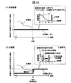
- Schematic diagram of a computer The flowchart which shows the process in the control center side terminal. The flowchart which shows the collection process of sensor information. The flowchart which shows the analysis process of sensor information. Schematic for demonstrating abnormality diagnosis processing.
- the schematic diagram which shows the stock quantity of the local warehouse in a parts inventory control system.
- FIG. 1 is a schematic diagram of a parts inventory control system 100 according to an embodiment of the present invention.
- the parts inventory control system 100 includes a central center terminal 110 disposed in a central center, a supplier terminal 140 disposed in a supplier supplying parts, and a central warehouse terminal disposed in a central warehouse. 150, a local warehouse terminal 160 arranged in the local warehouse, an operating device 170 to be managed such as preventive maintenance, and an operating device terminal 180 that monitors each operating device 170.
- the operating device 170 and the operating device terminal 180 are arranged at the site where the operating device 170 is installed, and parts to be attached to the operating device 170 included in the predetermined management area are stored in the management area.
- the local warehouse terminal 160 arranged in the assigned local warehouse is used for management.
- control center side terminal 110 the supplier terminal 140, the central warehouse terminal 150, the local warehouse terminal 160, and the operating equipment terminal 180 can transmit and receive information via the network 190.
- the parts to be attached to the operating equipment 170 are stored in a local warehouse assigned to the management area including the operating equipment 170 (the quantity of the stocked parts is If the number of parts to be stocked in the local warehouse is insufficient, it is replenished from the central warehouse (for parts stored in the central warehouse).
- the number is managed by the central warehouse terminal 150 arranged in the central warehouse), and when there is a shortage of parts stored in the central warehouse, it is ordered from the supplier (order of parts from the supplier) And delivery are managed by the supplier terminal 140).
- the number of parts stocked at each local warehouse, the quantity of parts stocked at the central warehouse, and the quantity of parts ordered from the supplier are controlled by the central center terminal 110.
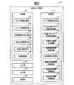
- FIG. 2 is a schematic diagram of the management center terminal 110.
- the central center terminal 110 includes a storage unit 111, a control unit 122, an input unit 130, an output unit 131, and a communication unit 132.
- the storage unit 111 includes a sensor information storage area 112, a sensor normal pattern information storage area 113, a failure sign pattern information storage area 114, a failure sign information storage area 115, an operating equipment information storage area 116, and a management information storage area. 117, a required component number information storage area 118, a parts inventory information storage area 119, and a parts replenishment information storage area 120.
- sensor information storage area 112 sensor information measured by a sensor installed in each operating device 170 is stored.
- sensor information having information specifying a value measured by a sensor installed in each operating device 170 and information specifying a time when the value is measured is used as the operating device.
- the management center terminal 110 acquires the sensor information from the operating device terminal 180 and stores it in the sensor information storage area 112 in association with the identification information for identifying the operating device 170 from which the sensor information is acquired. I remember it.
- the sensor normal pattern information storage area 113 information specifying a sensor normal pattern for determining that the value measured by the sensor installed in the operating device 170 is normal is stored.
- an upper limit value and a lower limit value that can determine that the value measured by a sensor installed in the operating device 170 is normal are stored in association with the time when the value is measured.
- the present invention is not limited to such an embodiment.
- failure sign pattern information storage area 114 information specifying a failure sign pattern that can be determined that the value measured by the sensor installed in the operating device 170 is a sign of failure is stored.
- a failure sign pattern table 114a as shown in FIG. 3 (schematic diagram of the failure sign pattern table 114a) is stored in the failure sign pattern information storage area 114.
- the failure sign pattern table 114a includes a failure sign pattern field 114b, a failure sign part number field 114c, a failure rate field 114d, a phenomenon field 114e, and an operating device number field 114f.
- a failure sign pattern which is a pattern of a change in a time series of values for determining that a value is measured by a sensor installed in the operating device 170 is a sign of failure. Information for identifying is stored. In the present embodiment, a failure sign pattern number for identifying each failure sign pattern is assigned, and the failure sign pattern number is stored in the failure sign pattern field 114b.
- the failure sign pattern information storage area 114 stores a failure sign pattern that identifies a time-series change in value in association with the failure sign pattern number.
- failure predictor part number field 114c a component that is likely to fail is specified when the value measured by the sensor installed in the operating device 170 is the failure predictor pattern specified in the failure predictor pattern field 114b. Information is stored. In the present embodiment, a part number is assigned to each part so as to be unique, and the part number is stored in the failure sign part number field 114c.
- the failure rate field 114d the failure rate that is the probability that a failure will occur when the value measured by the sensor installed in the operating device 170 becomes the failure predictor pattern specified in the failure predictor pattern field 114b is specified. Information to be stored is stored.
- the phenomenon field 114e information for specifying the content of a phenomenon that occurs when the value measured by the sensor installed in the operating device 170 becomes the failure sign pattern specified in the failure sign pattern field 114b is stored.
- the operating device number field 114f stores information for specifying the operating device 170 to which the part specified in the failure sign part number field 114c is attached.
- an identification number starting from “1” is assigned to each operating device 170 so as to be unique, and “ ⁇ ” that identifies the operating device is assigned to this identification number.
- the operating device number ( ⁇ 1,..., ⁇ m: m is a natural number of 1 or more) to which the symbol “is added is stored in the operating device number field 114f.
- the failure sign information storage area 115 is determined to have a sign of failure when the value measured by the sensor installed in the operation device 170 is determined to have a sign of failure, the operation is determined. Information for identifying the device 170 and parts is stored.
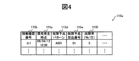
- a failure sign information table 115a as shown in FIG. 4 (schematic diagram of the failure sign information table 115a) is stored in the failure sign information storage area 115.
- the failure sign information table 115a has an operating device number field 115b, an abnormality occurrence time field 115c, a failure sign pattern field 115d, a failure sign part number field 115e, and a failure rate field 115f.
- the operating device number field 115b stores information (operating device number) for specifying the operating device from which the sensor value corresponding to the failure sign pattern is acquired.
- the abnormality occurrence time field 115c information specifying the time point when the sensor value corresponding to the failure sign pattern is acquired is stored.
- the information for specifying the time point at which the value of the sensor first corresponding to the failure sign pattern is acquired (the time when the value was acquired from the sensor information in which the value is stored) It is stored in the abnormality occurrence time field 115c.
- failure sign pattern field 115d identification information for identifying a failure sign pattern corresponding to a value measured by a sensor installed in the operating device 170 is stored.
- identification information (here, each part) for identifying a part that may fail in the failure sign pattern corresponding to the value measured by the sensor installed in the operating device 170. (Part number assigned so as to be unique).
- a failure occurs when it is determined that there is a failure sign in the failure sign pattern specified in the failure sign pattern field 115d based on a value measured by a sensor installed in the operating device 170. Information that specifies a failure rate that is a probability is stored.
- the operating device information storage area 116 stores information on each operating device 170 and information on components incorporated in the operating device 170.
- an operating device information table 116a as shown in FIG. 5 (schematic diagram of the operating device information table 116a) is stored in the operating device information storage area 116.
- the operating device information table 116a includes a management area field 116b, an operating device number field 116c, a part number field 116d, an attached number field 116e, a failure rate field 116f, and an operation start date field 116g.
- the management area field 116b stores information for specifying the management area to which the operating device 170 specified by the operating device number field 116c described later belongs.
- the operating device number field 116c stores information (operating device number) for specifying the operating device.
- part number field 116d Stored in the part number field 116d is information (here, a part number assigned to each part so as to be unique) that identifies a part to be incorporated in the operating equipment 170 specified by the operating equipment number field 116c.
- the attached number field 116e stores information for specifying the number of parts specified in the part number field 116d attached to the operating equipment 170 specified in the operating equipment number field 116c.
- the failure rate field 116f stores information for specifying the failure rate at which the component specified in the component number field 116d fails. Note that what is stored in the failure rate field 116f is the failure rate of the component when there is no failure sign.
- the operation start date field 116g stores information for specifying the date on which the operation device 170 specified by the operation device number field 116c has started operation.
- the management information storage area 117 stores information for specifying a lead time when parts are replenished in a central warehouse or a local warehouse and a threshold value when calculating the required number of parts.
- a management information table 117a as shown in FIG. 6 (schematic diagram of the management information table 117a) is stored in the management information storage area 117.
- the management information table 117a has a replenishment destination field 117b, a replenishment source field 117c, a replenishment lead time field 117d, and a shortage rate field 117e.
- replenishment destination field 117b information for specifying a central warehouse or a local warehouse for replenishing parts is stored.
- replenishment source field 117c information for specifying a central warehouse or a supplier as a component replenishment source is stored.
- the replenishment lead time field 117d stores information for specifying the replenishment lead time from part ordering to delivery.
- missing part rate field 117e information for specifying the probability that a part is missing is stored.
- a realistic value that allows the stockout of parts is set in this stockout rate field 117e.
- what lacks% of the missing item rate is the missing item probability.
- the part number information storage area 118 stores information for specifying the necessary number of parts to be stored in the local warehouse for each management area.
- a required component number information table 118a as shown in FIG. 7 (schematic diagram of the required component number information table 118a) is stored in the required component number information storage area 118.
- the necessary part number information table 118a includes a management area field 118b, a part number field 118c, a number field with a sign 118d, a failure rate field with a sign 118e, a number field with no sign 118f, and a failure rate field with no sign 118g.
- a necessary number field 118h, a replenishment source field 118i, a replenishment lead time field 118j, and a shortage rate field 118k are provided.
- the management area field 118b stores information for specifying the management area.
- an identification number starting from “1” is assigned so as to be unique to each management area, and “ ⁇ ” that identifies the management area is assigned to this identification number.
- the management area number ( ⁇ 1,..., ⁇ n: n is a natural number equal to or greater than 1) to which the symbol “is added is stored in the management area field 118b.
- the part number field 118c stores information (part number) for identifying a part attached to the operating device 170 included in the management area specified in the management area field 118b.
- the number field 118d with a sign there is a sign of failure among the parts specified in the part number field 118c and attached to the operating device 170 included in the management area specified in the management area field 118b. Information for specifying the number of parts is stored.
- failure rate field 118e with a sign information specifying the failure rate of the component identified in the part number field 118c and having a failure sign is stored.
- no-sign-number field 118f there is no sign of failure among the parts specified in the part number field 118c and attached to the operating device 170 included in the management area specified in the management area field 118b. Information for specifying the number of parts is stored.
- the failure rate field 118g without a sign stores information for identifying the failure rate of the component identified in the part number field 118c and having no failure sign.
- a part specified in the part number field 118c and attached to the operating device 170 included in the management area specified in the management area field 118b is stored in the management area. Information that specifies the required number is stored.
- replenishment source field 118i information specifying the replenishment source that receives the replenishment of the part specified in the part number field 118c is stored.
- replenishment lead time field 118j information for specifying the lead time when receiving the replenishment of the part specified in the part number field 118c is stored.
- the shortage rate field 118k information for specifying the probability of the shortage of the part specified in the part number field 118c is stored.
- the parts inventory information storage area 119 stores information for identifying the parts inventory in the central warehouse and the local warehouse.
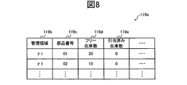
- a parts inventory information table 119a as shown in FIG. 8 (schematic diagram of the parts inventory information table 119a) is stored in the parts inventory information storage area 119 for each central warehouse and local warehouse.
- the parts inventory information table 119a has a management area field 119b, a part number field 119c, a free inventory quantity field 119d, and an allocated inventory quantity field 119e.
- the management area field 119b stores information for specifying a management area including a local warehouse that is a target for storing information in the parts inventory information table 119a.
- the management area field 119b is blank in the parts inventory information table 119a of the central warehouse.
- part number field 119c information for identifying a part stored in a central warehouse or a local warehouse, which is a target for storing information in the parts inventory information table 119a, is stored.
- reserved stock quantity field 119e information for specifying the quantity allocated to be allocated to another warehouse is stored.
- the parts replenishment information storage area 120 stores information for specifying items related to the replenishment of parts in the central warehouse and the local warehouse.
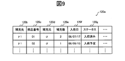
- a component supplement information table 120a as shown in FIG. 9 (schematic diagram of the component supplement information table 120a) is stored.
- the parts replenishment information table 120a includes a replenishment destination field 120b, a part number field 120c, a replenishment source field 120d, a replenishment number field 120e, an arrival date field 120f, and a status field 120g.
- replenishment destination field 120b information for specifying the replenishment destination of the part specified in the part number field 120c described later is stored.
- the part number field 120c stores information for specifying a part to be replenished.
- replenishment source field 120d information for specifying a replenishment source for replenishing the part specified in the part number field 120c is stored.
- replenishment number field 120e information for specifying the replenishment number for replenishing the part specified in the part number field 120c is stored.
- the arrival date field 120f stores information for specifying the date when the part specified in the part number field 120c is received at the replenishment destination specified in the replenishment destination field 120b.
- the status field 120g information for specifying the replenishment status of the part specified in the part number field 120c is stored. For example, a character string such as “stocked” if the part has been received, and “scheduled for arrival” if the part has not been received is stored.
- control unit 122 includes a sensor information collection unit 123, a sensor information analysis unit 124, an operating device state classification unit 125, a required component number calculation unit 126, a component inventory control unit 127, and an information update unit. 128.
- the sensor information collection unit 123 performs a process of collecting sensor information obtained from the working device 170 from the working device terminal 180 and storing it in the sensor information storage area 112 in association with the working device 170 from which the sensor information has been acquired.
- the sensor information analysis unit 124 performs a process of detecting an abnormality from the sensor information stored in the sensor information storage area 112 and identifying a component with a sign of failure.
- the operating equipment state classification unit 125 performs processing for calculating a part with a failure sign and a part without a failure sign for each management area.
- the required component number calculation unit 126 calculates the necessary number of components that need to be stored in each management area based on the number of components having a failure sign, the number of parts having no failure sign, and the respective failure rates. Processing to calculate is performed.
- the parts inventory control unit 127 stores the number of parts calculated by the parts required number calculation unit 126 in the local warehouse, the number of replenishments from the central warehouse to the local warehouse, and from the central warehouse to the supplier. A process of calculating the number of orders is performed.
- the information update unit 128 updates the information stored in the storage unit 111 of the management center side terminal 110.
- the information update unit 128 receives a change of information stored in the parts inventory information table 119a, the failure predictor pattern table 114a, the operating device information table 116a, and the like via the input unit 130, the related table Is read from the storage unit 111 and the corresponding information is updated.
- input of information may be accepted via the network 190 from each operating device terminal 180, the local warehouse terminal 160, the central warehouse terminal 150, the supplier terminal 140, and the like, and information change may be performed at these terminals. If there is, the input of information may be received in conjunction.
- the input unit 130 receives input of information.
- the output unit 131 outputs information.
- the communication unit 132 transmits and receives information via the network 190.
- the central center side terminal 110 described above is, for example, an external storage such as a CPU (Central Processing Unit) 901, a memory 902, and an HDD (Hard Disk Drive) as shown in FIG. 10 (schematic diagram of the computer 900).
- a general computer 900 including an input device 906 such as a display, an output device 907 such as a display, and a communication device 908 such as a NIC (Network Interface Card) for connecting to a communication network.
- NIC Network Interface Card
- the storage unit 111 can be realized by the CPU 901 using the memory 902 or the external storage device 903, and the control unit 122 loads a predetermined program stored in the external storage device 903 into the memory 902.
- the input unit 130 can be realized by using the input device 906 by the CPU 901, and the output unit 131 can be realized by using the output device 907 by the CPU 901.
- the communication unit 132 can be realized by the CPU 901 using the communication device 908.
- the predetermined program is downloaded from the storage medium 904 via the reading device 905 or from the network via the communication device 908 to the external storage device 903, and then loaded onto the memory 902 and executed by the CPU 901. You may do it. Alternatively, the program may be directly loaded on the memory 902 from the storage medium 904 via the reading device 905 or from the network via the communication device 908 and executed by the CPU 901.
- FIG. 11 is a flowchart showing processing in the central center terminal 110.
- the sensor information collection unit 123 of the control center side terminal 110 performs a process of collecting sensor information obtained from the operating device 170 from the operating device terminal 180 (S10). This process will be described in detail with reference to FIG.
- the sensor information analysis unit 124 performs processing for detecting an abnormality from the sensor information collected in step S10 and identifying a component with a sign of failure (S11). This process will be described in detail with reference to FIG.
- the operating device state classification unit 125 performs a process of classifying a part having a failure sign and a part having no failure sign and calculating the number of each part for each management area (S12). This process will be described in detail with reference to FIG.
- the required number of parts calculation unit 126 stores the number of parts having a failure sign, the number of parts having no failure sign, and the respective failure rates calculated in step S12 in each management area.
- a process of calculating the necessary number that needs to be stored is performed (S13). This process will be described in detail with reference to FIG.
- the parts inventory control unit 127 counts the number of replenishments from the central warehouse to the local warehouse and the order from the central warehouse to the supplier so that the necessary number of parts calculated in step S13 is stored in the local warehouse.
- the number is calculated (S14). This process will be described in detail with reference to FIG.
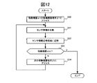
- FIG. 12 is a flowchart showing sensor information collection processing.
- the sensor information of the operating device 170 identified by the operating device numbers of ⁇ 1,..., ⁇ m is used as the operating devices of ⁇ 1,. It is assumed that the operating device terminal 180 identified by the terminal number is managed and stored.
- the sensor information collection unit 123 accesses the operating device terminal 180 identified by the first operating device terminal number ⁇ 1 via the communication unit 132 (S20).
- the sensor information collection unit 123 acquires the sensor information of the operating device 170 managed by the operating device terminal 180 from the accessed operating device terminal 180 (S21).
- the sensor information collection unit 123 stores the sensor information acquired in step S21 in the sensor information storage area 112 in association with the operating device number (S22).
- the sensor information collection unit 123 refers to the operating device information table 116 and determines whether or not the operating device 170 that acquired the sensor information in step S22 is the last operating device 170 (S23). If it is not the current operating device 170 (No in step S23), the process proceeds to step S24, and if it is the last operating device 170 (Yes in step S23), the process ends.
- step S24 the sensor information collecting unit 123 accesses the working device terminal 180 corresponding to the next working device terminal number ⁇ i (i is a natural number 1 ⁇ i ⁇ m). And the sensor information collection part 123 returns to step S21 and repeats a process.
- sensor information may be transmitted from the operating device terminal 180 to the general center terminal 110 at a predetermined time or the like.
- the sensor information may be transmitted to the general center terminal 110 from the operating device terminal 180 of the operating device 170 having an abnormality.
- FIG. 13 is a flowchart showing sensor information analysis processing.
- the sensor information analysis unit 124 acquires the sensor normal pattern stored in the sensor normal pattern information storage region 113 stored in the sensor normal pattern information storage region 113 of the storage unit 111 (S30).
- the sensor information analysis unit 124 acquires sensor information corresponding to the first operating device number ⁇ 1 from the sensor information storage area 112 (S31).
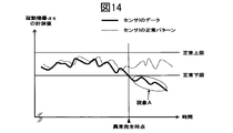
- the sensor information analysis unit 124 performs abnormality diagnosis based on whether or not the value included in the sensor information acquired in step S31 is determined to be abnormal with respect to the sensor normal pattern acquired in step S30 (S32). .
- an upper limit value and a lower limit value that can be determined to be normal are specified so that a sensor normal pattern is included.
- the value of the sensor information read in step S31 is not in the range between the upper limit value and the lower limit value, it is determined that there is an abnormality.
- the upper limit value and the lower limit value may be determined in advance so that the sensor normal pattern is included. For example, a predetermined value is added to or subtracted from the average value (in a specific period) of the sensor normal pattern. Thus, the upper limit value and the lower limit value may be calculated, and the upper limit value and the lower limit value are calculated by adding or subtracting a predetermined value to the value of the sensor normal pattern. Also good.
- step S33 If it is determined that there is an abnormality (Yes in step S33), the process proceeds to step S34. If it is not determined that there is an abnormality (No in step S33), the process proceeds to step S37.
- step S34 the sensor information analysis unit 124 acquires the failure sign pattern stored in the failure sign pattern information storage area 114.
- the sensor information analysis part 124 specifies the thing nearest to the pattern of the time-sequential change in the specific time interval of the value contained in the sensor information determined to be abnormal from the failure sign patterns acquired in step S34. Then, by identifying the record in which the failure sign pattern number of the identified failure sign pattern is stored in the failure sign pattern field 114b from the failure sign pattern table 114a, the part having the failure sign is specified (S35).
- the corresponding time (from the start of the pattern) between the failure sign pattern acquired in step S34 and the time-series change pattern at a specific time interval of the value included in the sensor information determined to be abnormal.
- the sum of the absolute values of the difference values in the elapsed time) may be the closest failure sign pattern, but is not limited to such a mode.
- the sensor information analysis unit 124 stores the information stored in the record identified in step S35 in the corresponding field of the failure sign information table 115a, and the sensor value included in the sensor information determined to be abnormal. Is stored in the abnormality occurrence time field 115c, thereby creating a new record in the failure sign information table 115a (S36).
- the sensor information analysis unit 124 refers to the operating device information table 116 and determines whether or not the operating device 170 that acquired the sensor information subjected to the abnormality diagnosis in step S32 is the last operating device 170 ( If it is not the last operating device 170 (No in step S37), the process proceeds to step S38, and if it is the last operating device 170 (Yes in step S37), the process ends.
- step S38 the sensor information analysis unit 124 acquires, from the sensor information storage area 112, the sensor information of the operating device 170 next to the operating device 170 that acquired the sensor information subjected to the abnormality diagnosis in step S32. And the sensor information analysis part 124 returns to step S32, and repeats a process.
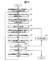
- FIG. 15 is a flowchart showing classification processing of the operating device state.
- the operating device state classification unit 125 acquires the operating device information table 116a from the operating device information storage area 116, and extracts the operating device 170 included in the first management area number ⁇ 1 from the operating device information table 116a (S40). .
- the operating device state classification unit 125 acquires the failure sign information table 115a from the failure sign information storage area 115, and narrows down the records of the failure sign information table 115a corresponding to the extracted operating device 170 (S41).
- the operating device state classification unit 125 extracts the part number of the part included in the record narrowed down in step S41 from the failure sign part number field 115e, and the number of parts having the sign of failure from the extracted part number.
- X is calculated (S42).
- step S42 a natural number order is assigned to each part specified by the extracted part number in order from "1".
- the operating device state classification unit 125 selects a part corresponding to the first item from the parts having a failure sign included in the record extracted in step S42 (S43).
- the operating device state classification unit 125 classifies the operating device 170 having a failure sign and the operating device 170 having no failure sign (S44).
- the operating device state classification unit 125 identifies a record that includes a part number corresponding to the selected component in the failure sign component number field 115e of the record extracted in step S42, and the operating device number field of the identified record By extracting the operating device number from 115b, the operating device 170 having a failure sign is identified.
- the operating device state classification unit 125 selects a component number corresponding to the selected component in the component number field 116c of the record of the operating device information table 116a corresponding to the operating device 170 included in the target management area. , And the operation device 170 corresponding to the operation device number included in the operation device number field 116c of the specified record is excluded from the operation device 170 having a failure sign, and the operation having no failure sign is performed.
- the device 170 is specified.
- the operating device state classification unit 125 calculates the number of selected parts in the operating device 170 having a failure sign and the number of selected parts in the operating device 170 having no failure sign classified in step S45. (S46).
- the operating device state classification unit 125 stores the operating device number of the operating device 170 having a failure sign or the operating device 170 having no failure sign and the part number of the selected part classified in step S45 in the same record.
- the number of parts in each classification is calculated by specifying the record in the operating device information table 116a, and adding the value of the attachment number field 116e of the specified record in each classification.
- the operating device state classification unit 125 selects the management region number of the management region to be evaluated, the component number of the selected component, and the operating device 170 with the failure sign calculated in step S45. And the failure rate of the component with the failure sign (specified from the failure rate field 116f of the operation device information table 116a), and the selected component in the operation device 170 without the failure sign calculated in step S45.
- the number and the failure rate of a component with a failure sign (specified from the failure rate field 116f of the operating device information table 116a) are specified, and the management area field 118b, the component number field 118c, and the predictor of the required component number information table 118a, respectively.
- the operating device state classification unit 125 specifies the record of the management information table 117a in which the management region number for identifying the management region from which the operating device is extracted is stored in the replenishment destination field 117b, and replenishment source of the identified record The information stored in the field 117c, the replenishment lead time field 117d, and the missing part rate field 117e is acquired, and the obtained information is used as the replenishment source field 118i, the replenishment lead time field 118j, and the missing part, respectively. Store in the rate field 118k.
- step S44 determines whether or not the item of the part classified in step S44 is the last item (S47), and if it is not the last item (No in step S47).
- step S48 the part of the next item is selected, and the process returns to step S44 to repeat the process.
- step S49 the process proceeds to step S49.
- step S49 the operating device state classification unit 125 determines whether or not the management area from which the operating device 170 is extracted is the last management area. If the management area is the last management area (Yes in step S49). If the process is terminated and it is not the last management area (No in step S49), the process proceeds to step S50.
- step S50 the operating device state classification unit 125 extracts the operating device 170 included in the next management area ⁇ i (i is a natural number satisfying 1 ⁇ i ⁇ n) from the operating device information table 116a (S50). Then, the operating device state classification unit 125 returns to Step S41 and repeats the process.
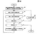
- FIG. 16 is a flowchart showing a process for calculating the required number of parts.
- the required component number calculation unit 126 acquires the required component number information table 118a stored in the required component number information storage area 118, and is managed in the management area corresponding to the first management area number ⁇ 1.
- the part (top record) is selected (S60).
- the required component number calculation unit 126 calculates the required number of selected components (S61).
- the required number of parts is calculated using, for example, a fault distribution formula in the Poisson distribution as shown in the following formula (1).
- ⁇ is the failure rate
- n is the number of samples
- t is the operating time
- r is the number of failures
- P (r) is the failure probability
- the necessary component number calculation unit 126 first samples the failure rate with a sign stored in the failure rate field 118c with a sign corresponding to the selected component in the failure rate ⁇ in the equation (1).
- the number stored in the number field 118d with a sign corresponding to the selected part is input, and the replenishment lead time stored in the replenishment lead time field 118j corresponding to the selected part is input as the operation time t. To do.
- the required component number calculation unit 126 obtains a cumulative value by sequentially adding the values of P (r) calculated by substituting positive integers such as 0, 1,...
- the number of failures r when the accumulated value reaches (1-probability of missing item) is obtained.
- the value of r obtained in this way is set as the necessary number when there is a failure sign.
- the necessary component number calculation unit 126 selects the failure rate stored in the failure-free failure rate field 118g corresponding to the selected component as the failure rate ⁇ in the equation (1) as the sample number n.
- the number stored in the unsigned number field 118f corresponding to the selected part is input as the replenishment lead time stored in the replenishment lead time field 118j corresponding to the selected part.
- the required component number calculation unit 126 obtains a cumulative value obtained by sequentially adding the values of P (r) calculated by substituting 0, 1,... The number of failures r at the time when (1-out of stock probability) is reached is obtained. The value of r obtained in this way is set as the required number when there is no failure sign.
- the necessary number of local warehouses in the selected management area of the part can be calculated. To do.
- the required component number calculation unit 126 stores the required number of components calculated in step S61 in the required number field 118h of the required component number information table 118a (S62).
- step S63 the required component number calculation unit 126 determines whether or not the component for which the required number has been calculated in step S61 is the last component (S63). If it is not the last component (No in step S63), In step S64, the next part is selected, and the process returns to step S61 to repeat the process. On the other hand, if it is the last part (Yes in step S63), the process proceeds to step S65.
- step S65 the required component number calculation unit 126 determines whether the required number of components managed in the management area corresponding to the last management area number ⁇ n has been calculated. (Yes in step S65), the process ends. If it is not the last management area (No in step S65), the process proceeds to step S66.
- step S66 the required component number calculation unit 126 selects the first (topmost record) component managed in the management area corresponding to the next management area number ⁇ i, and returns to step S61. repeat.
- FIG. 17 is a flowchart showing parts inventory control processing.
- the parts inventory control unit 127 acquires the necessary part number information table 118a stored in the necessary part number information storage area 118, and manages the first part managed in the management area corresponding to the first management area number ⁇ 1.
- the part (top record) is selected (S70).
- the parts inventory control unit 127 extracts the necessary number of the selected parts from the necessary number field 118h of the necessary part quantity information table 118a, and also the stock quantity in the management area that is the target of the selected parts. Is acquired from the free stock quantity field 119d of the parts stock information table 119a (S71).
- the parts inventory control unit 127 determines whether or not the required number of selected parts exceeds the number of parts in stock (S72), and if so (Yes in step S72), The process proceeds to step S73, and if not (No in step S72), the process proceeds to step S74.
- step S73 the parts inventory control unit 127 calculates the number of parts to be replenished by subtracting the number of parts in stock from the required number of selected parts, and enters the number of replenishment field 120e in the parts replenishment information table 120a.
- Store (S73) the parts inventory control unit 127 stores the management area number of the target management area in the replenishment destination field 120b in the record storing the number of replenishments, and the part of the selected part in the part number field 120c. The number is stored, and information for specifying the central warehouse is stored in the replenishment source field 120d.
- step S74 the parts inventory control unit 127 determines whether or not the selected part is the last part managed in the target management area. If the selected part is not the last part (step S74). No), the next part is selected in step S75, and the process returns to step S71 to repeat the process. On the other hand, if it is the last part (Yes in step S74), the process proceeds to step S76.
- step S76 the parts inventory control unit 127 determines whether or not the management area for managing the parts for which the number of replenishments has been calculated is the last management area. If the management area is not the last management area (No in step S76). ) Go to Step S77, and if it is the last management area (Yes in Step S76), go to Step S78.
- step S77 the parts inventory control unit 127 selects the first (topmost record) part managed in the management area corresponding to the next management area number ⁇ i in the necessary part number information table 118a. Then, the process returns to step S71 and the process is repeated.
- step S78 the parts inventory control unit 127 acquires, from the storage unit 111, the parts inventory information table 119a, the parts replenishment information table 120a, and the necessary component quantity information table 118a associated with the central warehouse. The first part stored in the part replenishment information table 120a is selected.
- the parts inventory control unit 127 determines whether or not the replenishment number of the selected parts exceeds the inventory quantity of the central warehouse (specified by the free inventory quantity field 119d of the parts inventory information table 119a of the central warehouse). (S79). Then, the parts inventory control unit 127 proceeds to step S80 when the number of replenishments of the selected parts exceeds the number of inventory in the central warehouse (Yes in step S79), and proceeds to step S80 when the number does not exceed (in step S79). No in S79), the process proceeds to step S81.
- step S80 the parts inventory control unit 127 calculates, as a shortage quantity, a quantity in which the replenishment number of the selected part exceeds the stock quantity in the central warehouse, and specifies the shortage quantity and the selected part. And generating a purchase order data in a predetermined format including, and transmitting the data to the supplier terminal 140 via the communication unit 132.
- step S81 the parts inventory control unit 127 outputs, to the output unit 131, an instruction for replenishing the selected number of parts to be replenished from the central warehouse to the local warehouse in the target management area.
- the parts inventory control unit 127 reflects the processing result in step S80 or step S81 in the parts inventory information table 119a and the parts replenishment information table 120a associated with the central warehouse (S82).
- the parts inventory control unit 127 sets the inventory quantity stored in the free inventory quantity field 119d of the parts inventory information table 119a in the allocated inventory quantity field 119e.
- the value in the replenishment number field 120e of the record of the replenishment information table 120a corresponding to the selected part is set to the number of stocks in the central warehouse, and in the arrival date field 120f, the necessary part number information table 118a on the date processed.
- the date obtained by adding the lead time specified in the replenishment lead time field 118i is calculated, and the calculated date is stored.
- the parts inventory control unit 127 stores the character string “arrival scheduled” in the status field 120g of the record.
- the parts inventory control unit 127 newly adds a record similar to the record of the replenishment information table 120a corresponding to the selected part, and sets the value of the replenishment number field 120e of the added record to the quantity ordered from the supplier.
- the arrival date field 120f the lead time from the central warehouse to the local warehouse on the processing date (specified by the replenishment lead time field 118i of the necessary part quantity information table 118a) and the lead time from the supplier to the central warehouse (in advance) Setting), and the calculated date is stored.
- the parts inventory control unit 127 stores the character string “arrival scheduled” in the status field 120g of the record.
- the parts inventory control unit 127 subtracts the replenishment number of the selected parts from the inventory quantity stored in the free inventory quantity field 119d of the parts inventory information table 119a, The subtracted quantity is stored in the reserved inventory quantity field 119e.
- the parts inventory control unit 127 determines whether or not the selected part is the last part (S83). If the selected part is not the last part (No in step S83), the next part is determined in step S84. Is selected, and the process returns to step S79 to repeat the process. On the other hand, if it is the last part (Yes in step S83), the process is terminated.
- FIG. 18 Schematic diagram showing the stock amount of the local warehouse in the parts inventory control system 100
- a certain amount of parts judged to be necessary should be managed.
- the present invention when there is a sign of failure in a part, it is necessary to increase the number of stocks in the local warehouse that manages the part (FIG. 18B). The stock burden can be reduced.
- parts are ordered from the supplier.
- the present invention is not limited to this mode. For example, parts from other local warehouses May be procured.
- processing is performed by the central center terminal 110, but the present invention is not limited to such a mode, and the supplier terminal 140, the central warehouse terminal 150, the local warehouse terminal 160, the operating equipment 170, and at least one of the operation equipment terminals 180 is configured to perform the same processing as the central center terminal 110, so that the central center terminal 110 performs at least one of these terminals. It is possible to cause a certain process to be performed.
- control center terminal 111 storage unit 112 sensor information storage area 113 sensor normal pattern information storage area 114 failure sign pattern information storage area 115 failure sign information storage area 116 operating equipment information storage area 117 management information storage area 118 parts Necessary number information storage area 119 Parts inventory information storage area 120 Parts replenishment information storage area 122 Control unit 123 Sensor information collection unit 124 Sensor information analysis unit 125 Operating equipment state classification unit 126 Parts required number calculation unit 127 Parts inventory control unit 128 Information update Unit 130 Input unit 131 Output unit 132 Communication unit 140 Supplier terminal 150 Central warehouse terminal 160 Local warehouse terminal 170 Operating equipment 180 Operating equipment terminal
Landscapes
- Business, Economics & Management (AREA)
- Engineering & Computer Science (AREA)
- Human Resources & Organizations (AREA)
- Economics (AREA)
- Strategic Management (AREA)
- General Physics & Mathematics (AREA)
- Physics & Mathematics (AREA)
- Tourism & Hospitality (AREA)
- Theoretical Computer Science (AREA)
- Marketing (AREA)
- General Business, Economics & Management (AREA)
- Quality & Reliability (AREA)
- Entrepreneurship & Innovation (AREA)
- Operations Research (AREA)
- Development Economics (AREA)
- Game Theory and Decision Science (AREA)
- Automation & Control Theory (AREA)
- General Engineering & Computer Science (AREA)
- Manufacturing & Machinery (AREA)
- Educational Administration (AREA)
- Accounting & Taxation (AREA)
- Finance (AREA)
- Health & Medical Sciences (AREA)
- General Health & Medical Sciences (AREA)
- Primary Health Care (AREA)
- Management, Administration, Business Operations System, And Electronic Commerce (AREA)
- General Factory Administration (AREA)
Abstract
部品の需要予測をより精密に行い、部品の適切な在庫管理を行うことのできる技術を提供すること。 センサ情報収集部123で、稼働機器170より得られたセンサ情報を収集する処理を行い、センサ情報解析部124で、収集したセンサ情報より、異常を検知し、故障予兆のある部品を特定する処理を行い、稼働機器状態分類部125で、故障予兆の有る部品と、故障予兆の無い部品と、を特定し、部品必要数算出部126で、故障予兆の有る部品の個数と、故障予兆の無い部品の個数と、それぞれの故障率と、により在庫として必要な部品の必要数を算出する処理を行う。
Description
本発明は、稼働機器のための部品の在庫を管理する技術に関する。
昇降機や鉄道等の稼動機器には、点検、調整、部品交換などの継続的な予防保全作業が必要である。しかも、現場での予防保全作業はできる限り少ない回数で、かつ、短い時間で完了させることが望まれるため、予防保全作業は時間計画保全から状態監視保全へ、さらに遠隔からの状態監視保全へ、と移行する傾向にある。
状態監視保全では、稼動機器の状態を監視しながら部品交換を行うため、部品をぎりぎりまで使い切ることができる。従って、予め定められた時間で部品を交換する時間計画保全と比較して、状態監視保全では、部品の交換回数を減らすことができると考えられる。
しかしながら、状態監視保全では、点検結果で交換が必要と判断された場合や、故障が発生した場合に、部品を交換する必要があり、計画的に部品を購入することが難しく、結果として予防保全用の部品の在庫を多めに保有して対応せざるを得ない。つまり、状態監視保全による部品交換は、現場作業コストという面では低減が期待できるが、在庫コストという面では深刻な問題となる。
この点、例えば、特許文献1には、受注実績を活用した需要予測を行うことにより、予防保全用の部品の在庫適正化を図る技術が開示されている。
以上に記載した特許文献1に記載の技術は、過去の受注実績から将来の需要を予測するものであるため、受注実績の件数が多く、需要の波形が連続的で安定的に推移しているような部品に対しては有効な技術である。
しかしながら、予防保全用の部品のように、需要の波形が離散的な間欠需要である場合には、特許文献1に記載の技術では、予測誤差が大きくなりやすく、結局、部品の在庫を多めに保持して対応せざるを得ない。
そこで、本発明は、部品の需要予測をより精密に行い、部品の適切な在庫管理を行うことのできる技術を提供することを目的とする。
以上の課題を解決するため、本発明は、稼働機器をセンサで監視し、当該稼働機器に故障の予兆があるものと、故障の予兆が無いものと、に分類して、各々の分類に応じた在庫の必要量を算出する。
例えば、本発明は、複数の稼働機器のための部品の在庫を管理する端末であって、前記稼働機器の状態を監視するセンサから得られる値のパターンであって前記稼働機器に使用されている部品の故障予兆を示す故障予兆パターン、当該故障予兆パターンが見られる場合に故障が発生するおそれのある部品、および、当該故障予兆がある場合に当該部品が故障する確率である第一の故障率、を特定する情報を有する故障予兆パターン情報と、前記稼働機器、前記稼働機器で使用される部品、前記稼働機器に使用されている当該部品の個数、および、故障予兆がない場合に当該部品が故障する確率である第二の故障率、を特定する情報を有する稼働機器情報と、を記憶する記憶部と、制御部と、を備え、前記制御部は、前記稼働機器の状態を監視するセンサから得られた値が異常と判断された場合に、当該値のパターンに対応する故障予兆パターンを前記故障予兆パターン情報から特定する処理と、特定した故障予兆パターンにより故障するおそれのある部品を故障予兆部品として特定する処理と、前記センサから得られた値が異常と判断された前記稼働機器において、前記故障予兆部品が使用されている個数を、故障予兆有り個数として前記稼働機器情報から特定する処理と、前記複数の稼働機器の内、前記センサから得られた値が異常と判断された前記稼働機器以外の他の前記稼働機器において、前記故障予兆部品を同じ部品が使用されている個数を、故障予兆無し個数として前記稼働機器情報から特定する処理と、前記故障予兆有り個数の部品が、前記第一の故障率で故障する場合に在庫として必要となる第一の必要数を算出する処理と、前記故障予兆無し個数の部品が、前記第二の故障率で故障する場合に在庫として必要となる第二の必要数を算出する処理と、第一の必要数と第二の必要数を合算することで、前記故障予兆部品と同じ部品の在庫必要数を算出する処理と、を行うことを特徴とする。
上述のように、本発明によれば、部品の需要予測をより精密に行い、部品の適切な在庫管理を行うことができる。
図1は、本発明の一実施形態である部品在庫制御システム100の概略図である。
図示するように、部品在庫制御システム100は、統括センタに配置されている統括センタ端末110と、部品を供給するサプライヤに配置されているサプライヤ端末140と、中央倉庫に配置されている中央倉庫端末150と、地方倉庫に配置されている地方倉庫端末160と、予防保全等の管理の対象となる稼働機器170と、各々の稼働機器170を監視する稼働機器端末180と、を備える。
そして、稼働機器170及び稼働機器端末180は、稼働機器170が設置されている現場に配置されており、予め定められた管理領域に含まれる稼働機器170に取り付けるための部品は、当該管理領域に割り当てられている地方倉庫に配置されている地方倉庫端末160で管理するようにしている。
さらに、統括センタ側端末110、サプライヤ端末140、中央倉庫端末150、地方倉庫端末160及び稼働機器端末180は、ネットワーク190を介して、情報を送受信することができるようにされている。
このような部品在庫制御システム100では、稼働機器170に取り付けられる部品を、当該稼働機器170が含まれる管理領域に割り当てられている地方倉庫に備蓄しておき(備蓄している部品の数量等は、当該管理領域に配置されている地方倉庫端末160で管理)、地方倉庫に備蓄しておく部品の数が足りない場合等には、中央倉庫から補充し(中央倉庫に備蓄している部品の数等は、当該中央倉庫に配置されている中央倉庫端末150で管理)、中央倉庫で備蓄している部品が不足等した場合には、サプライヤから取り寄せるようにしている(サプライヤでの部品の受注及び配送はサプライヤ端末140で管理)。
そして、各々の地方倉庫で備蓄する部品の数量、中央倉庫で備蓄する部品の数量、サプライヤに発注する部品の数量は、統括センタ端末110で制御する。
図2は、統括センタ端末110の概略図である。
図示するように、統括センタ端末110は、記憶部111と、制御部122と、入力部130と、出力部131と、通信部132と、を備える。
記憶部111は、センサ情報記憶領域112と、センサ正常パターン情報記憶領域113と、故障予兆パターン情報記憶領域114と、故障予兆情報記憶領域115と、稼働機器情報記憶領域116と、管理情報記憶領域117と、部品必要数情報記憶領域118と、部品在庫情報記憶領域119と、部品補充情報記憶領域120と、を備える。
センサ情報記憶領域112には、各稼働機器170に設置されたセンサで計測されたセンサ情報が記憶される。
例えば、本実施形態においては、各々の稼働機器170に設置されたセンサで計測された値を特定する情報と、当該値が計測された時間を特定する情報と、を有するセンサ情報を、稼働機器端末180に記憶し、統括センタ端末110は、稼働機器端末180より当該センサ情報を取得して、センサ情報が取得された稼働機器170を識別する識別情報に対応付けて、センサ情報記憶領域112に記憶するようにしている。
センサ正常パターン情報記憶領域113には、稼働機器170に設置されたセンサで計測された値が、正常と判断するためのセンサ正常パターンを特定する情報が記憶される。
例えば、本実施形態においては、稼働機器170に設置されたセンサで計測された値を正常と判断することのできる上限値及び下限値が、当該値が計測された時間に対応付けて記憶されているが、このような態様に限定されるわけではない。
故障予兆パターン情報記憶領域114には、稼働機器170に設置されたセンサで計測された値が、故障を予兆するものであると判断することのできる故障予兆パターンを特定する情報が記憶される。
例えば、本実施形態においては、図3(故障予兆パターンテーブル114aの概略図)に示すような故障予兆パターンテーブル114aが故障予兆パターン情報記憶領域114に記憶される。
図示するように、故障予兆パターンテーブル114aは、故障予兆パターンフィールド114bと、故障予兆部品番号フィールド114cと、故障率フィールド114dと、現象フィールド114eと、稼働機器番号フィールド114fと、を有する。
故障予兆パターンフィールド114bには、稼働機器170に設置されたセンサで計測された値に対して、故障を予兆するものであると判断するための値の時系列における変化のパターンである故障予兆パターンを特定する情報が格納される。なお、本実施形態では、各々の故障予兆パターンを識別するための故障予兆パターン番号が割り振られており、当該故障予兆パターン番号が故障予兆パターンフィールド114bに格納される。
なお、故障予兆パターン情報記憶領域114には、当該故障予兆パターン番号に対応させて、値の時系列変化を特定する故障予兆パターンが記憶されている。
故障予兆部品番号フィールド114cには、稼働機器170に設置されたセンサで計測された値が、故障予兆パターンフィールド114bで特定される故障予兆パターンとなる場合に、故障するおそれのある部品を特定する情報が格納される。本実施形態においては、各々の部品に一意となるように部品番号が割り振られており、当該部品番号が故障予兆部品番号フィールド114cに格納される。
故障率フィールド114dには、稼働機器170に設置されたセンサで計測された値が、故障予兆パターンフィールド114bで特定される故障予兆パターンとなる場合に、故障が発生する確率である故障率を特定する情報が格納される。
現象フィールド114eには、稼働機器170に設置されたセンサで計測された値が、故障予兆パターンフィールド114bで特定される故障予兆パターンとなる場合に生ずる現象の内容を特定する情報が格納される。
稼働機器番号フィールド114fには、故障予兆部品番号フィールド114cで特定される部品が取り付けられている稼働機器170を特定する情報が格納される。ここで、本実施形態においては、各々の稼働機器170に一意となるように「1」から連番となる識別番号が割り振られており、この識別番号に稼働機器であることを特定する「α」の記号を付加した稼働機器番号(α1,・・・,αm:mは1以上の自然数)が、稼働機器番号フィールド114fに格納される。
図2に戻り、故障予兆情報記憶領域115には、稼働機器170に設置されたセンサで計測された値が、故障の予兆が有ると判断された場合に、故障予兆があると判断された稼働機器170及び部品を特定する情報が格納される。
例えば、本実施形態においては、図4(故障予兆情報テーブル115aの概略図)に示すような故障予兆情報テーブル115aが故障予兆情報記憶領域115に記憶される。
図示するように、故障予兆情報テーブル115aは、稼働機器番号フィールド115bと、異常発生時点フィールド115cと、故障予兆パターンフィールド115dと、故障予兆部品番号フィールド115eと、故障率フィールド115fと、を有する。
稼働機器番号フィールド115bには、故障予兆パターンに該当したセンサの値が取得された稼働機器を特定する情報(稼働機器番号)が格納される。
異常発生時点フィールド115cには、故障予兆パターンに該当したセンサの値が取得された時点を特定する情報が格納される。本実施形態では、故障予兆パターンに最初に該当するセンサの値が取得された時点(当該値が格納されているセンサ情報から取得された、当該値が計測された時間)を特定する情報が、異常発生時点フィールド115cに格納される。
故障予兆パターンフィールド115dには、稼働機器170に設置されたセンサで計測された値が該当した故障予兆パターンを識別するための識別情報が格納される。
故障予兆部品番号フィールド115eには、稼働機器170に設置されたセンサで計測された値が該当した故障予兆パターンにおいて、故障するおそれのある部品を識別するための識別情報(ここでは、各々の部品に一意となるように割り振られている部品番号)が格納される。
故障率フィールド115fには、稼働機器170に設置されたセンサで計測された値が、故障予兆パターンフィールド115dで特定される故障予兆パターンで故障予兆があると判断された場合に、故障が発生する確率である故障率を特定する情報が格納される。
図2に戻り、稼働機器情報記憶領域116には、各々の稼働機器170に関する情報と、当該稼働機器170に組み込まれている部品に関する情報と、が記憶される。
例えば、本実施形態においては、図5(稼働機器情報テーブル116aの概略図)に示すような稼働機器情報テーブル116aが、稼働機器情報記憶領域116に記憶される。
稼働機器情報テーブル116aは、管理領域フィールド116bと、稼働機器番号フィールド116cと、部品番号フィールド116dと、取付個数フィールド116eと、故障率フィールド116fと、稼働開始日フィールド116gと、を有する。
管理領域フィールド116bには、後述する稼働機器番号フィールド116cで特定される稼働機器170が属する管理領域を特定する情報が格納される。
稼働機器番号フィールド116cには、稼働機器を特定する情報(稼働機器番号)が格納される。
部品番号フィールド116dには、稼働機器番号フィールド116cで特定される稼働機器170に組み込まれる部品を特定する情報(ここでは、各々の部品に一意となるように割り振られている部品番号)が格納される。
取付個数フィールド116eには、稼働機器番号フィールド116cで特定される稼働機器170に、部品番号フィールド116dで特定される部品が取り付けられる個数を特定する情報が格納される。
故障率フィールド116fには、部品番号フィールド116dで特定される部品が、故障する故障率を特定する情報が格納される。なお、故障率フィールド116fに格納されるのは、故障予兆がない場合の部品の故障率である。
稼働開始日フィールド116gには、稼働機器番号フィールド116cで特定される稼働機器170が稼働を開始した年月日を特定する情報が格納される。
図2に戻り、管理情報記憶領域117には、中央倉庫又は地方倉庫で部品を補充する際のリードタイム、および、必要な部品数を算出する際の閾値を特定する情報が格納される。
例えば、本実施形態においては、図6(管理情報テーブル117aの概略図)に示すような管理情報テーブル117aが、管理情報記憶領域117に記憶される。
管理情報テーブル117aは、補充先フィールド117bと、補充元フィールド117cと、補充リードタイムフィールド117dと、欠品率フィールド117eと、を有する。
補充先フィールド117bには、部品を補充する中央倉庫又は地方倉庫を特定する情報が格納される。
補充元フィールド117cには、部品の補充元となる中央倉庫又はサプライヤを特定する情報が格納される。
補充リードタイムフィールド117dには、部品の発注から納品までの補充リードタイムを特定する情報が格納される。
欠品率フィールド117eには、部品の欠品が生ずる確率を特定する情報が格納される。なお、ここでの欠品率を小さな値にすればするほど、故障に対して部品を蓄積しておく個数が多くなるため、部品の欠品を許す現実的な値をこの欠品率フィールド117eに格納しておけばよい。なお、欠品率の%を外したもの(例えば、欠品率1%を0.01としたもの)が、欠品確率となる。
図2に戻り、部品必要数情報記憶領域118には、各々の管理領域毎に、地方倉庫に備蓄しておくべき部品の必要数を特定する情報が格納される。
例えば、本実施形態においては、図7(部品必要数情報テーブル118aの概略図)に示すような部品必要数情報テーブル118aが、部品必要数情報記憶領域118に記憶される。
部品必要数情報テーブル118aは、管理領域フィールド118bと、部品番号フィールド118cと、予兆有り個数フィールド118dと、予兆有り故障率フィールド118eと、予兆無し個数フィールド118fと、予兆無し故障率フィールド118gと、必要数フィールド118hと、補充元フィールド118iと、補充リードタイムフィールド118jと、欠品率フィールド118kと、を有する。
管理領域フィールド118bには、管理領域を特定する情報が格納される。ここで、本実施形態においては、各々の管理領域に一意となるように、「1」から連番となる識別番号が割り当てられており、この識別番号に管理領域であることを特定する「γ」の記号を付加した管理領域番号(γ1,・・・,γn:nは1以上の自然数)が、管理領域フィールド118bに格納される。
部品番号フィールド118cには、管理領域フィールド118bで特定される管理領域に含まれる稼働機器170に取り付けられる部品を特定する情報(部品番号)が格納される。
予兆有り個数フィールド118dには、部品番号フィールド118cで特定される部品であって、管理領域フィールド118bで特定される管理領域に含まれる稼働機器170に取り付けられている部品のうち、故障予兆の有る部品の個数を特定する情報が格納される。
予兆有り故障率フィールド118eには、部品番号フィールド118cで特定される部品であって、故障予兆の有る部品の故障率を特定する情報が格納される。
予兆無し個数フィールド118fには、部品番号フィールド118cで特定される部品であって、管理領域フィールド118bで特定される管理領域に含まれる稼働機器170に取り付けられている部品のうち、故障予兆の無い部品の個数を特定する情報が格納される。
予兆無し故障率フィールド118gには、部品番号フィールド118cで特定される部品であって、故障予兆の無い部品の故障率を特定する情報が格納される。
必要数フィールド118hには、部品番号フィールド118cで特定される部品であって、管理領域フィールド118bで特定される管理領域に含まれる稼働機器170に取り付けられる部品を、当該管理領域において備蓄しておく必要のある必要数を特定する情報が格納される。
補充元フィールド118iには、部品番号フィールド118cで特定される部品の補充を受ける補充元を特定する情報が格納される。
補充リードタイムフィールド118jには、部品番号フィールド118cで特定される部品の補充を受ける際のリードタイムを特定する情報が格納される。
欠品率フィールド118kには、部品番号フィールド118cで特定される部品の欠品が生ずる確率を特定する情報が格納される。
図2に戻り、部品在庫情報記憶領域119には、中央倉庫及び地方倉庫における部品の在庫を特定する情報が格納される。
例えば、本実施形態においては、図8(部品在庫情報テーブル119aの概略図)に示すような部品在庫情報テーブル119aが、中央倉庫、および、地方倉庫毎に、部品在庫情報記憶領域119に記憶される。
部品在庫情報テーブル119aは、管理領域フィールド119bと、部品番号フィールド119cと、フリー在庫数フィールド119dと、引当済み在庫数フィールド119eと、を有する。
管理領域フィールド119bには、部品在庫情報テーブル119aに情報を格納する対象である地方倉庫が含まれる管理領域を特定する情報が格納される。ここで、本実施形態では、中央倉庫については管理領域に属しないため、中央倉庫の部品在庫情報テーブル119aでは、管理領域フィールド119bは空欄にされている。
部品番号フィールド119cには、部品在庫情報テーブル119aに情報を格納する対象である中央倉庫又は地方倉庫に備蓄する部品を特定する情報が格納される。
フリー在庫数フィールド119dには、部品番号フィールド119cで特定される部品の在庫数を特定する情報が格納される。
引当済み在庫数フィールド119eには、他の倉庫に引き当てるために割り当てられた数量を特定する情報が格納される。
図2に戻り、部品補充情報記憶領域120には、中央倉庫及び地方倉庫において部品を補充する際に、当該部品の補充に関連する事項を特定する情報が記憶される。
例えば、本実施形態においては、図9(部品補充情報テーブル120aの概略図)に示すような部品補充情報テーブル120aが格納される。
部品補充情報テーブル120aは、補充先フィールド120bと、部品番号フィールド120cと、補充元フィールド120dと、補充数フィールド120eと、入荷日フィールド120fと、ステータスフィールド120gと、を有する。
補充先フィールド120bには、後述する部品番号フィールド120cで特定される部品の補充先を特定する情報が格納される。
部品番号フィールド120cには、補充を行う部品を特定する情報が格納される。
補充元フィールド120dには、部品番号フィールド120cで特定される部品を補充する補充元を特定する情報が格納される。
補充数フィールド120eには、部品番号フィールド120cで特定される部品を補充する補充数を特定する情報が格納される。
入荷日フィールド120fには、部品番号フィールド120cで特定される部品が、補充先フィールド120bで特定される補充先に入荷される年月日を特定する情報が格納される。
ステータスフィールド120gには、部品番号フィールド120cで特定される部品の補充状況を特定する情報が格納される。例えば、当該部品が入荷済みであれば「入荷済み」、当該部品の入荷前であれば「入荷予定」、といった文字列が格納される。
図2に戻り、制御部122は、センサ情報収集部123と、センサ情報解析部124と、稼働機器状態分類部125と、部品必要数算出部126と、部品在庫制御部127と、情報更新部128と、を有する。
センサ情報収集部123は、稼働機器端末180から稼働機器170より得られたセンサ情報を収集し、センサ情報が取得された稼働機器170と対応付けてセンサ情報記憶領域112に記憶する処理を行う。
センサ情報解析部124は、センサ情報記憶領域112に記憶されたセンサ情報より、異常を検知し、故障予兆のある部品を特定する処理を行う。
稼働機器状態分類部125は、故障予兆の有る部品と、故障予兆の無い部品と、を管理領域毎に算出する処理を行う。
部品必要数算出部126は、故障予兆の有る部品の個数と、故障予兆の無い部品の個数と、それぞれの故障率と、により各々の管理領域で備蓄しておく必要のある部品の必要数を算出する処理を行う。
部品在庫制御部127は、部品必要数算出部126で算出された部品の必要数が、地方倉庫に備蓄されるように、中央倉庫から地方倉庫への補充数、および、中央倉庫からサプライヤへの発注数、を算出する処理を行う。
情報更新部128は、統括センタ側端末110の記憶部111に記憶されている情報を更新する。
例えば、情報更新部128は、部品在庫情報テーブル119a、故障予兆パターンテーブル114a、稼動機器情報テーブル116a等に格納されている情報の変更を、入力部130等を介して、受け付けると、関連するテーブルを記憶部111から読込み、該当する情報を更新する。なお、各稼働機器端末180、地方倉庫側端末160、中央倉庫端末150、サプライヤ端末140、等からネットワーク190を介して、情報の入力を受け付けてもよく、また、これらの端末で情報の変更があった場合に、連動して情報の入力を受け付けるようにしてもよい。
入力部130は、情報の入力を受け付ける。
出力部131は、情報を出力する。
通信部132は、ネットワーク190を介して情報の送受信を行う。
以上に記載した統括センタ側端末110は、例えば、図10(コンピュータ900の概略図)に示すような、CPU(Central Processing Unit)901と、メモリ902と、HDD(Hard Disk Drive)等の外部記憶装置903と、CD-ROM(Compact Disk Read Only Memory)やDVD-ROM(Digital Versatile Disk Read Only Memory)等の可搬性を有する記憶媒体904に対して情報を読み書きする読書装置905と、キーボードやマウスなどの入力装置906と、ディスプレイなどの出力装置907と、通信ネットワークに接続するためのNIC(Network Interface Card)等の通信装置908と、を備えた一般的なコンピュータ900で実現できる。
例えば、記憶部111は、CPU901がメモリ902又は外部記憶装置903を利用することにより実現可能であり、制御部122は、外部記憶装置903に記憶されている所定のプログラムをメモリ902にロードしてCPU901で実行することで実現可能であり、入力部130は、CPU901が入力装置906を利用することで実現可能であり、出力部131は、CPU901が出力装置907を利用することで実現可能であり、通信部132は、CPU901が通信装置908を利用することで実現可能である。
この所定のプログラムは、読書装置905を介して記憶媒体904から、あるいは、通信装置908を介してネットワークから、外部記憶装置903にダウンロードされ、それから、メモリ902上にロードされてCPU901により実行されるようにしてもよい。また、読書装置905を介して記憶媒体904から、あるいは、通信装置908を介してネットワークから、メモリ902上に直接ロードされ、CPU901により実行されるようにしてもよい。
図11は、統括センタ側端末110での処理を示すフローチャートである。
まず、統括センタ側端末110のセンサ情報収集部123が、稼働機器端末180から稼働機器170より得られたセンサ情報を収集する処理を行う(S10)。この処理については、図12を用いて詳細に説明する。
次に、センサ情報解析部124が、ステップS10で収集されたセンサ情報より、異常を検知し、故障予兆のある部品を特定する処理を行う(S11)。この処理については、図13を用いて詳細に説明する。
次に、稼働機器状態分類部125が、故障予兆の有る部品と、故障予兆の無い部品と、を分類して、それぞれの個数を管理領域毎に算出する処理を行う(S12)。この処理については、図15を用いて詳細に説明する。
次に、部品必要数算出部126が、ステップS12で算出された、故障予兆の有る部品の個数と、故障予兆の無い部品の個数と、それぞれの故障率と、より各々の管理領域で備蓄しておく必要のある必要数を算出する処理を行う(S13)。この処理については、図16を用いて詳細に説明する。
次に、部品在庫制御部127が、ステップS13で算出された部品の必要数が、地方倉庫に備蓄されるように、中央倉庫から地方倉庫への補充数、および、中央倉庫からサプライヤへの発注数、を算出する処理を行う(S14)。この処理については、図17を用いて詳細に説明する。
図12は、センサ情報の収集処理を示すフローチャートである。
ここで、本実施形態においては、α1,・・・,αmの稼働機器番号で識別される稼働機器170のセンサ情報を、これらの稼働機器番号に対応するβ1,・・・,βmの稼働機器端末番号で識別される稼働機器端末180が管理し、記憶しているものとする。
まず、センサ情報収集部123は、通信部132を介して、最初の稼働機器端末番号β1で識別される稼働機器端末180にアクセスする(S20)。
次に、センサ情報収集部123は、アクセスした稼働機器端末180から、当該稼働機器端末180が管理する稼働機器170のセンサ情報を取得する(S21)。
そして、センサ情報収集部123は、ステップS21で取得したセンサ情報を、稼働機器番号に対応付けて、センサ情報記憶領域112に記憶する(S22)。
次に、センサ情報収集部123は、稼働機器情報テーブル116を参照して、ステップS22でセンサ情報を取得した稼働機器170が最後の稼働機器170であるか否かを判断し(S23)、最後の稼働機器170ではない場合には(ステップS23でNo)、ステップS24に進み、最後の稼働機器170である場合には(ステップS23でYes)、処理を終了する。
ステップS24では、センサ情報収集部123は、次の稼働機器端末番号βi(iは、1≦i≦mなる自然数)に対応する稼働機器端末180にアクセスする。そして、センサ情報収集部123は、ステップS21に戻り処理を繰り返す。
なお、図12のフローチャートでは、統括センタ端末110から稼働機器端末180にアクセスする例を示したが、別の方法でセンサ情報を収集してもよい。例えば、稼働機器端末180から統括センタ端末110に、予め定められた時間等にセンサ情報を送信するようにしても良い。
また、稼働機器端末180において、図13に示すセンサ情報の解析処理を実行した後、異常がある稼動機器170の稼働機器端末180から、センサ情報を統括センタ端末110に送信するようにしてもよい。
図13は、センサ情報の解析処理を示すフローチャートである。
まず、センサ情報解析部124は、記憶部111のセンサ正常パターン情報記憶領域113に記憶されているセンサ正常パターン情報記憶領域113に記憶されているセンサ正常パターンを取得する(S30)。
次に、センサ情報解析部124は、最初の稼働機器番号α1に対応するセンサ情報をセンサ情報記憶領域112から取得する(S31)。
そして、センサ情報解析部124は、ステップS31で取得したセンサ情報に含まれる値が、ステップS30で取得したセンサ正常パターンに対して異常と判断されるか否かで、異常診断を行う(S32)。
例えば、本実施形態においては、図14(異常診断処理を説明するための概略図)に示すように、センサ正常パターンが含まれるように、正常と判断することのできる上限値及び下限値を特定し、ステップS31で読み込んだセンサ情報の値が当該上限値及び下限値の範囲にない場合に、異常と判断する。
なお、上限値と下限値については、センサ正常パターンが含まれるように予め定めておけばよいが、例えば、センサ正常パターンの(特定の期間における)平均値に予め定められた値を加算又は減算することで上限値と下限値とを算出するようにしてもよく、また、センサ正常パターンの値に予め定められた値を加算又は減算することで上限値と下限値とを算出するようにしてもよい。
そして、異常があると判断された場合には(ステップS33でYes)、ステップS34に進み、異常があると判断されなかった場合には(ステップS33でNo)、ステップS37に進む。
ステップS34では、センサ情報解析部124は、故障予兆パターン情報記憶領域114に記憶されている故障予兆パターンを取得する。
そして、センサ情報解析部124は、ステップS34で取得した故障予兆パターンの中から、異常と判断されたセンサ情報に含まれる値の特定の時間間隔における時系列変化のパターンに最も近いものを特定し、特定した故障予兆パターンの故障予兆パターン番号が故障予兆パターンフィールド114bに格納されているレコードを故障予兆パターンテーブル114aから特定することで、故障予兆の有る部品を特定する(S35)。
例えば、本実施形態では、ステップS34で取得した故障予兆パターンと、異常と判断されたセンサ情報に含まれる値の特定の時間間隔における時系列変化のパターンと、の対応する時間(パターンの開始からの経過時間等)における差分値の絶対値の和が最も小さいものを、最も近い故障予兆パターンとすればよいが、このような態様に限定されるわけではない。
次に、センサ情報解析部124は、ステップS35で特定したレコードに格納されている情報を故障予兆情報テーブル115aの対応するフィールドに格納するとともに、異常と判断されたセンサ情報に含まれるセンサの値の取得時間を特定する情報を異常発生時点フィールド115cに格納することで、故障予兆情報テーブル115aに新たなレコードを作成する(S36)。
そして、センサ情報解析部124は、稼働機器情報テーブル116を参照して、ステップS32で異常診断を行ったセンサ情報を取得した稼働機器170が最後の稼働機器170であるか否かを判断し(S37)、最後の稼働機器170ではない場合には(ステップS37でNo)、ステップS38に進み、最後の稼働機器170である場合には(ステップS37でYes)、処理を終了する。
ステップS38では、センサ情報解析部124は、ステップS32で異常診断を行ったセンサ情報を取得した稼働機器170の次の稼働機器170のセンサ情報をセンサ情報記憶領域112から取得する。そして、センサ情報解析部124は、ステップS32に戻り処理を繰り返す。
図15は、稼動機器状態の分類処理を示すフローチャートである。
まず、稼働機器状態分類部125は、稼働機器情報記憶領域116から稼働機器情報テーブル116aを取得し、最初の管理領域番号γ1に含まれる稼働機器170を稼働機器情報テーブル116aから抽出する(S40)。
次に、稼働機器状態分類部125は、故障予兆情報記憶領域115から故障予兆情報テーブル115aを取得し、抽出した稼働機器170に対応する故障予兆情報テーブル115aのレコードを絞り込む(S41)。
次に、稼働機器状態分類部125は、ステップS41で絞り込んだレコードに含まれている部品の部品番号を故障予兆部品番号フィールド115eから抽出し、抽出した部品番号より故障予兆の有る部品の品目数Xを算出する(S42)。なお、ステップS42では、抽出した部品番号で特定される各々の部品に、「1」から順に自然数による順番を割り当てておく。
そして、稼働機器状態分類部125は、ステップS42で抽出したレコードに含まれている故障予兆の有る部品の内から、一番目の品目に対応する部品を選択する(S43)。
次に、稼働機器状態分類部125は、故障予兆の有る稼働機器170と、故障予兆のない稼働機器170と、を分類する(S44)。
例えば、稼働機器状態分類部125は、ステップS42で抽出したレコードの故障予兆部品番号フィールド115eに、選択された部品に対応する部品番号が含まれるレコードを特定し、特定したレコードの稼働機器番号フィールド115bから稼働機器番号を抽出することにより、故障予兆の有る稼働機器170を特定する。
そして、稼働機器状態分類部125は、対象となっている管理領域に含まれる稼働機器170に対応する稼働機器情報テーブル116aのレコードの部品番号フィールド116cのうち、選択された部品に対応する部品番号が含まれるレコードを特定し、特定したレコードの稼働機器番号フィールド116cに含まれる稼働機器番号に対応する稼働機器170のうち、故障予兆の有る稼働機器170を除いたものから、故障予兆のない稼働機器170を特定する。
次に、稼働機器状態分類部125は、ステップS45で分類した故障予兆の有る稼働機器170における選択された部品の個数と、故障予兆の無い稼働機器170における選択された部品の個数と、を算出する(S46)。
例えば、稼働機器状態分類部125は、ステップS45で分類した故障予兆の有る稼働機器170又は故障予兆の無い稼働機器170の稼働機器番号と、選択された部品の部品番号と、が同じレコードに格納されている稼働機器情報テーブル116aのレコードを特定し、特定したレコードの取付個数フィールド116eの値を各々の分類において加算することで、各々の分類における部品個数を算出する。
次に、稼働機器状態分類部125は、評価の対象となっている管理領域の管理領域番号と、選択された部品の部品番号と、ステップS45で算出された故障予兆の有る稼働機器170における選択された部品の個数と、故障予兆の有る部品の故障率(稼働機器情報テーブル116aの故障率フィールド116fより特定)と、ステップS45で算出された故障予兆の無い稼働機器170における選択された部品の個数と、故障予兆の有る部品の故障率(稼働機器情報テーブル116aの故障率フィールド116fより特定)と、を特定し、それぞれ部品必要数情報テーブル118aの管理領域フィールド118b、部品番号フィールド118c、予兆有り個数フィールド118d、予兆有り故障率フィールド118e、故障無し個数フィールド118f、予兆無し故障率フィールド118gに格納する(S46)。さらに、稼働機器状態分類部125は、稼働機器を抽出した管理領域を識別する管理領域番号が、補充先フィールド117bに格納されている管理情報テーブル117aのレコードを特定し、特定したレコードの補充元フィールド117c、補充リードタイムフィールド117d及び欠品率フィールド117eに格納されている情報を取得し、取得した情報を、それぞれ部品必要数情報テーブル118aの補充元フィールド118i、補充リードタイムフィールド118j及び欠品率フィールド118kに格納する。
そして、稼働機器状態分類部125は、ステップS44で分類を行った部品の品目が、最後の品目であるか否かを判断し(S47)、最後の品目でない場合には(ステップS47でNo)、ステップS48において次の品目の部品を選択し、ステップS44に戻り処理を繰り返す。一方、最後の品目である場合には(ステップS47でYes)、ステップS49に進む。
ステップS49では、稼働機器状態分類部125は、稼働機器170を抽出した管理領域が、最後の管理領域であるか否かを判断し、最後の管理領域である場合には(ステップS49でYes)、処理を終了し、最後の管理領域でない場合には(ステップS49でNo)、ステップS50に進む。
ステップS50では、稼働機器状態分類部125は、次の管理領域γi(iは、1≦i≦nを満たす自然数)に含まれる稼働機器170を稼働機器情報テーブル116aから抽出する(S50)。そして、稼働機器状態分類部125は、ステップS41に戻り処理を繰り返す。
図16は、部品の必要数を算出する処理を示すフローチャートである。
まず、部品必要数算出部126は、部品必要数情報記憶領域118に記憶されている部品必要数情報テーブル118aを取得し、最初の管理領域番号γ1に対応する管理領域で管理されている第一番目(一番上のレコード)の部品を選択する(S60)。
次に、部品必要数算出部126は、選択した部品の必要数を算出する(S61)。
部品の必要数は、例えば、下記の(1)式に示すようなポアソン分布における故障分布の式を用いて算出する。

ここで、λは故障率、nはサンプル数、tは動作時間、rは故障数、P(r)は故障確率である。
具体的には、部品必要数算出部126は、まず、(1)式において、故障率λに、選択された部品に対応する予兆有り故障率フィールド118cに格納された予兆有り故障率を、サンプル数nに、選択された部品に対応する予兆有り個数フィールド118dに格納された個数を、動作時間tに、選択された部品に対応する補充リードタイムフィールド118jに格納された補充リードタイムを、入力する。
そして、部品必要数算出部126は、故障数rに、順に0、1、・・・と正の整数を代入して算出したP(r)の値を順に加算した累積値を求めて、求めた累積値が(1-欠品確率)に到達した時点の故障数rを求める。このようにして求めたrの値を故障予兆が有る場合の必要数とする。
同様に、部品必要数算出部126は、(1)式において、故障率λに、選択された部品に対応する予兆無し故障率フィールド118gに格納された故障率を、サンプル数nに、選択された部品に対応する予兆無し個数フィールド118fに格納された個数を、動作時間tに、選択された部品に対応する補充リードタイムフィールド118jに格納された補充リードタイムを、入力する。
そして、部品必要数算出部126は、故障数rに、順に0、1、・・・と代入して算出したP(r)の値を順に加算した累積値を求めて、求めた累積値が(1-欠品確率)に到達した時点の故障数rを求める。このようにして求めたrの値を故障予兆が無い場合の必要数とする。
そして、以上のようにして算出した故障予兆が有る場合の必要数と、故障予兆が無い場合の必要数と、を合算することで、その部品の選択された管理領域における地方倉庫の必要数とする。
次に、部品必要数算出部126は、ステップS61で算出した部品の必要数を、部品必要数情報テーブル118aの必要数フィールド118hに格納する(S62)。
そして、部品必要数算出部126は、ステップS61で必要数を算出した部品が最後の部品であるか否かを判断し(S63)、最後の部品ではない場合には(ステップS63でNo)、ステップS64において次の部品を選択して、ステップS61に戻り処理を繰り返す。一方、最後の部品である場合には(ステップS63でYes)、ステップS65に進む。
ステップS65では、部品必要数算出部126は、最後の管理領域番号γnに対応する管理領域で管理されている部品の必要数を算出したか否かを判断し、最後の管理領域である場合には(ステップS65でYes)、処理を終了し、最後の管理領域ではない場合には(ステップS65でNo)、ステップS66に進む。
ステップS66では、部品必要数算出部126は、次の管理領域番号γiに対応する管理領域で管理されている第一番目(一番上のレコード)の部品を選択して、ステップS61に戻り処理を繰り返す。
図17は、部品在庫の制御処理を示すフローチャートである。
まず、部品在庫制御部127は、部品必要数情報記憶領域118に記憶されている部品必要数情報テーブル118aを取得し、最初の管理領域番号γ1に対応する管理領域で管理されている第一番目(一番上のレコード)の部品を選択する(S70)。
次に、部品在庫制御部127は、選択された部品の必要数を部品必要数情報テーブル118aの必要数フィールド118hより抽出し、また、選択された部品の対象となっている管理領域における在庫数を、部品在庫情報テーブル119aのフリー在庫数フィールド119dから取得する(S71)。
次に、部品在庫制御部127は、選択された部品の必要数が、当該部品の在庫数を超えているか否かを判定し(S72)、超えている場合には(ステップS72でYes)、ステップS73に進み、超えていない場合には(ステップS72でNo)、ステップS74に進む。
ステップS73では、部品在庫制御部127は、選択された部品の必要数から、当該部品の在庫数を差し引くことにより、当該部品の補充数を算出し、部品補充情報テーブル120aの補充数フィールド120eに格納する(S73)。また、部品在庫制御部127は、補充数を格納したレコードにおいて、補充先フィールド120bに、対象となっている管理領域の管理領域番号を格納し、部品番号フィールド120cに、選択された部品の部品番号を格納し、補充元フィールド120dに中央倉庫を特定する情報を格納する。
ステップS74では、部品在庫制御部127は、選択された部品が、対象となっている管理領域で管理されている最後の部品か否かを判断し、最後の部品ではない場合には(ステップS74でNo)、ステップS75において次の部品を選択して、ステップS71に戻り処理を繰り返す。一方、最後の部品である場合には(ステップS74でYes)、ステップS76に進む。
ステップS76では、部品在庫制御部127は、補充数を算出した部品を管理する管理領域が、最後の管理領域であるか否かを判断し、最後の管理領域でない場合には(ステップS76でNo)、ステップS77に進み、最後の管理領域である場合には(ステップS76でYes)、ステップS78に進む。
ステップS77では、部品在庫制御部127は、部品必要数情報テーブル118aにおいて、次の管理領域番号γiに対応する管理領域で管理されている第一番目(一番上のレコード)の部品を選択して、ステップS71に戻り処理を繰り返す。
一方、ステップS78では、部品在庫制御部127は、中央倉庫に対応付けられている部品在庫情報テーブル119aと、部品補充情報テーブル120aと、部品必要数情報テーブル118aと、を記憶部111より取得して、部品補充情報テーブル120aに格納されている第一番目の部品を選択する。
次に、部品在庫制御部127は、選択された部品の補充数が、中央倉庫の在庫数(中央倉庫の部品在庫情報テーブル119aのフリー在庫数フィールド119dで特定)を超えているか否かを判断する(S79)。そして、部品在庫制御部127は、選択された部品の補充数が、中央倉庫の在庫数を超えている場合には(ステップS79でYes)、ステップS80に進み、超えていない場合には(ステップS79でNo)、ステップS81に進む。
ステップS80では、部品在庫制御部127は、選択された部品の補充数が、中央倉庫の在庫数を超えている数量を不足数量として算出し、当該不足数量と、選択された部品を特定する情報と、を含む予め定められたフォーマットの発注データを生成し、通信部132を介してサプライヤ端末140に送信する処理を行う。
一方、ステップS81では、部品在庫制御部127は、選択された部品の補充数を、中央倉庫より、対象となっている管理領域の地方倉庫に補充する旨の指示を出力部131に出力する。
そして、部品在庫制御部127は、ステップS80又はステップS81での処理結果を、中央倉庫に対応付けられている部品在庫情報テーブル119a、および、部品補充情報テーブル120a、に反映させる(S82)。
具体的には、ステップS80の処理を行った場合には、部品在庫制御部127は、部品在庫情報テーブル119aのフリー在庫数フィールド119dに格納されている在庫数を、引当済み在庫数フィールド119eに移すとともに、選択された部品に対応する補充情報テーブル120aのレコードの補充数フィールド120eの値を、中央倉庫の在庫数数にして、入荷日フィールド120fに、処理した日付に部品必要数情報テーブル118aの補充リードタイムフィールド118iで特定されるリードタイムを加えた日付を算出して、算出した日付を格納する。さらに、部品在庫制御部127は、当該レコードのステータスフィールド120gに、「入荷予定」の文字列を格納する。
さらに、部品在庫制御部127は、選択された部品に対応する補充情報テーブル120aのレコードと同様のレコードを新たに追加し、追加したレコードの補充数フィールド120eの値を、サプライヤに発注した数量に変更し、入荷日フィールド120fに、処理した日付に中央倉庫から当該地方倉庫へのリードタイム(部品必要数情報テーブル118aの補充リードタイムフィールド118iで特定)及びサプライヤから中央倉庫へのリードタイム(予め設定)、を加えた日付を算出して、算出した日付を格納する。さらに、部品在庫制御部127は、当該レコードのステータスフィールド120gに、「入荷予定」の文字列を格納する。
一方、ステップS81の処理を行った場合には、部品在庫制御部127は、部品在庫情報テーブル119aのフリー在庫数フィールド119dに格納されている在庫数より、選択された部品の補充数を差し引き、差し引いた数量を引当済み在庫数フィールド119eに格納する。
次に、部品在庫制御部127は、選択された部品が、最後の部品か否かを判断し(S83)、最後の部品ではない場合には(ステップS83でNo)、ステップS84において次の部品を選択して、ステップS79に戻り処理を繰り返す。一方、最後の部品である場合には(ステップS83でYes)、処理を終了する。
以上のように、例えば、図18(部品在庫制御システム100での地方倉庫の在庫量を示す概略図)に示すように、従来では、必要と判断される一定の量の部品を管理しておかなければならなかったところ(図18A)、本発明によれば、部品に故障予兆がある場合に、当該部品を管理する地方倉庫の在庫数を増やせばよいため(図18B)、地方倉庫での在庫負担を軽減することができる。
以上に記載した実施形態においては、特定の地方倉庫の在庫数で部品の必要数を満たすことができない場合には、中央倉庫から部品を補充するようにしているが、このような態様に限定されず、他の地方倉庫から部品を補充するようにしてもよい。
また、中央倉庫の在庫数で部品の必要数を満たすことができない場合には、サプライヤに部品を発注するようにしているが、このような態様に限定されず、例えば、他の地方倉庫から部品を調達するようにしてもよい。
さらに、以上に記載した実施形態においては、統括センタ端末110で処理を行うようにしているが、このような態様に限定されず、サプライヤ端末140、中央倉庫端末150、地方倉庫端末160、稼働機器170及び稼働機器端末180の少なくとも何れか一つ以上に、統括センタ端末110と同様の処理を行うように構成することで、この少なくとも何れか一つ以上の端末で、統括センタ端末110で行っている処理を行わせるようにすることの可能である。
100 部品在庫制御システム
110 統括センタ端末
111 記憶部
112 センサ情報記憶領域
113 センサ正常パターン情報記憶領域
114 故障予兆パターン情報記憶領域
115 故障予兆情報記憶領域
116 稼働機器情報記憶領域
117 管理情報記憶領域
118 部品必要数情報記憶領域
119 部品在庫情報記憶領域
120 部品補充情報記憶領域
122 制御部
123 センサ情報収集部
124 センサ情報解析部
125 稼働機器状態分類部
126 部品必要数算出部
127 部品在庫制御部
128 情報更新部
130 入力部
131 出力部
132 通信部
140 サプライヤ端末
150 中央倉庫端末
160 地方倉庫端末
170 稼働機器
180 稼働機器端末
110 統括センタ端末
111 記憶部
112 センサ情報記憶領域
113 センサ正常パターン情報記憶領域
114 故障予兆パターン情報記憶領域
115 故障予兆情報記憶領域
116 稼働機器情報記憶領域
117 管理情報記憶領域
118 部品必要数情報記憶領域
119 部品在庫情報記憶領域
120 部品補充情報記憶領域
122 制御部
123 センサ情報収集部
124 センサ情報解析部
125 稼働機器状態分類部
126 部品必要数算出部
127 部品在庫制御部
128 情報更新部
130 入力部
131 出力部
132 通信部
140 サプライヤ端末
150 中央倉庫端末
160 地方倉庫端末
170 稼働機器
180 稼働機器端末
Claims (11)
- 複数の稼働機器のための部品の在庫を管理する端末であって、
前記稼働機器の状態を監視するセンサから得られる値のパターンであって前記稼働機器に使用されている部品の故障予兆を示す故障予兆パターン、当該故障予兆パターンが見られる場合に故障が発生するおそれのある部品、および、当該故障予兆がある場合に当該部品が故障する確率である第一の故障率、を特定する情報を有する故障予兆パターン情報と、
前記稼働機器、前記稼働機器で使用される部品、前記稼働機器に使用されている当該部品の個数、および、故障予兆がない場合に当該部品が故障する確率である第二の故障率、を特定する情報を有する稼働機器情報と、を記憶する記憶部と、制御部と、を備え、
前記制御部は、
前記稼働機器の状態を監視するセンサから得られた値が異常と判断された場合に、当該値のパターンに対応する故障予兆パターンを前記故障予兆パターン情報から特定する処理と、
特定した故障予兆パターンにより故障するおそれのある部品を故障予兆部品として特定する処理と、
前記センサから得られた値が異常と判断された前記稼働機器において、前記故障予兆部品が使用されている個数を、故障予兆有り個数として前記稼働機器情報から特定する処理と、
前記複数の稼働機器の内、前記センサから得られた値が異常と判断された前記稼働機器以外の他の前記稼働機器において、前記故障予兆部品を同じ部品が使用されている個数を、故障予兆無し個数として前記稼働機器情報から特定する処理と、
前記故障予兆有り個数の部品が、前記第一の故障率で故障する場合に在庫として必要となる第一の必要数を算出する処理と、
前記故障予兆無し個数の部品が、前記第二の故障率で故障する場合に在庫として必要となる第二の必要数を算出する処理と、
第一の必要数と第二の必要数を合算することで、前記故障予兆部品と同じ部品の在庫必要数を算出する処理と、
を行うことを特徴とする端末。 - 請求項1に記載の端末であって、
前記制御部は、
前記故障予兆有り個数の部品が、当該部品のリードタイムにおいて前記第一の故障率で故障する場合に在庫として必要となる第一の必要数を、予め定められた欠品確率以下の数量となるようにポアソン分布により算出すること、
を特徴とする端末。 - 請求項1に記載の端末であって、
前記制御部は、
前記故障予兆無し個数の部品が、当該部品のリードタイムにおいて前記第二の故障率で故障する場合に在庫として必要となる第二の必要数を、予め定められた欠品確率以下の数量となるようにポアソン分布により算出すること、
を特徴とする端末。 - 請求項1に記載の端末であって、
前記記憶部は、前記稼働機器毎に、前記稼働機器が含まれる予め定められた領域、前記稼働機器に使用される部品、および、前記領域に割り当てられている倉庫における当該部品の在庫数、を特定する部品在庫情報を記憶しており、
前記制御部は、
前記センサから得られた値が異常と判断された前記稼働機器の前記故障予兆部品と同じ部品の在庫数を、前記部品在庫情報から特定する処理と、
前記在庫必要数が、特定した在庫数よりも多い場合には、前記在庫必要数から当該在庫数を減算した値を補充数として特定する処理と、
前記補充数を、前記センサから得られた値が異常と判断された前記稼働機器が含まれる予め定められた領域に割り当てられている倉庫以外の他の倉庫から補充すべき指示を出力部に出力する処理と、を行うこと、
を特徴とする端末。 - 請求項4に記載の端末であって、
前記制御部は、
前記補充数が、前記センサから得られた値が異常と判断された前記稼働機器が含まれる予め定められた領域に割り当てられている倉庫以外の他の倉庫の在庫数よりも多い場合には、前記補充数から前記他の倉庫の在庫数を減算した不足数を発注する処理を行うこと、
を特徴とする端末。 - コンピュータを、複数の稼働機器のための部品の在庫を管理する端末として機能させるプログラムであって、
前記コンピュータを、
前記稼働機器の状態を監視するセンサから得られる値のパターンであって前記稼働機器に使用されている部品の故障予兆を示す故障予兆パターン、当該故障予兆パターンが見られる場合に故障が発生するおそれのある部品、および、当該故障予兆がある場合に当該部品が故障する確率である第一の故障率、を特定する情報を有する故障予兆パターン情報と、
前記稼働機器、前記稼働機器で使用される部品、前記稼働機器に使用されている当該部品の個数、および、故障予兆がない場合に当該部品が故障する確率である第二の故障率、を特定する情報を有する稼働機器情報と、を記憶する記憶手段、制御手段として機能させ、
前記制御手段に、
前記稼働機器の状態を監視するセンサから得られた値が異常と判断された場合に、当該値のパターンに対応する故障予兆パターンを前記故障予兆パターン情報から特定する処理と、
特定した故障予兆パターンにより故障するおそれのある部品を故障予兆部品として特定する処理と、
前記センサから得られた値が異常と判断された前記稼働機器において、前記故障予兆部品が使用されている個数を、故障予兆有り個数として前記稼働機器情報から特定する処理と、
前記複数の稼働機器の内、前記センサから得られた値が異常と判断された前記稼働機器以外の他の前記稼働機器において、前記故障予兆部品を同じ部品が使用されている個数を、故障予兆無し個数として前記稼働機器情報から特定する処理と、
前記故障予兆有り個数の部品が、前記第一の故障率で故障する場合に在庫として必要となる第一の必要数を算出する処理と、
前記故障予兆無し個数の部品が、前記第二の故障率で故障する場合に在庫として必要となる第二の必要数を算出する処理と、
第一の必要数と第二の必要数を合算することで、前記故障予兆部品と同じ部品の在庫必要数を算出する処理と、
を行わせることを特徴とするプログラム。 - 請求項6に記載のプログラムであって、
前記制御手段に、
前記故障予兆有り個数の部品が、当該部品のリードタイムにおいて前記第一の故障率で故障する場合に在庫として必要となる第一の必要数を、予め定められた欠品確率以下の数量となるようにポアソン分布により算出させること、
を特徴とするプログラム。 - 請求項6に記載のプログラムであって、
前記制御手段に、
前記故障予兆無し個数の部品が、当該部品のリードタイムにおいて前記第二の故障率で故障する場合に在庫として必要となる第二の必要数を、予め定められた欠品確率以下の数量となるようにポアソン分布により算出させること、
を特徴とするプログラム。 - 請求項6に記載のプログラムであって、
前記記憶手段に、前記稼働機器毎に、前記稼働機器が含まれる予め定められた領域、前記稼働機器に使用される部品、および、前記領域に割り当てられている倉庫における当該部品の在庫数、を特定する部品在庫情報を記憶させ、
前記制御手段に、
前記センサから得られた値が異常と判断された前記稼働機器の前記故障予兆部品と同じ部品の在庫数を、前記部品在庫情報から特定する処理と、
前記在庫必要数が、特定した在庫数よりも多い場合には、前記在庫必要数から当該在庫数を減算した値を補充数として特定する処理と、
前記補充数を、前記センサから得られた値が異常と判断された前記稼働機器が含まれる予め定められた領域に割り当てられている倉庫以外の他の倉庫から補充すべき指示を出力部に出力する処理と、を行わせること、
を特徴とするプログラム。 - 請求項9に記載のプログラムであって、
前記制御手段に、
前記補充数が、前記センサから得られた値が異常と判断された前記稼働機器が含まれる予め定められた領域に割り当てられている倉庫以外の他の倉庫の在庫数よりも多い場合には、前記補充数から前記他の倉庫の在庫数を減算した不足数を発注する処理を行わせること、
を特徴とするプログラム。 - 稼働機器の状態を監視するセンサから得られる値のパターンであって前記稼働機器に使用されている部品の故障予兆を示す故障予兆パターン、当該故障予兆パターンが見られる場合に故障が発生するおそれのある部品、および、当該故障予兆がある場合に当該部品が故障する確率である第一の故障率、を特定する情報を有する故障予兆パターン情報と、
前記稼働機器、前記稼働機器で使用される部品、前記稼働機器に使用されている当該部品の個数、および、故障予兆がない場合に当該部品が故障する確率である第二の故障率、を特定する情報を有する稼働機器情報と、を記憶する記憶部と、制御部と、を備える端末が、複数の稼働機器のための部品の在庫を管理する在庫管理方法であって、
前記制御部が、前記稼働機器の状態を監視するセンサから得られた値が異常と判断された場合に、当該値のパターンに対応する故障予兆パターンを前記故障予兆パターン情報から特定する処理を行う過程と、
前記制御部が、特定した故障予兆パターンにより故障するおそれのある部品を故障予兆部品として特定する処理を行う過程と、
前記制御部が、前記センサから得られた値が異常と判断された前記稼働機器において、前記故障予兆部品が使用されている個数を、故障予兆有り個数として前記稼働機器情報から特定する処理を行う過程と、
前記制御部が、前記複数の稼働機器の内、前記センサから得られた値が異常と判断された前記稼働機器以外の他の前記稼働機器において、前記故障予兆部品を同じ部品が使用されている個数を、故障予兆無し個数として前記稼働機器情報から特定する処理を行う過程と、
前記制御部が、前記故障予兆有り個数の部品が、前記第一の故障率で故障する場合に在庫として必要となる第一の必要数を算出する処理を行う過程と、
前記制御部が、前記故障予兆無し個数の部品が、前記第二の故障率で故障する場合に在庫として必要となる第二の必要数を算出する処理を行う過程と、
前記制御部が、第一の必要数と第二の必要数を合算することで、前記故障予兆部品と同じ部品の在庫必要数を算出する処理を行う過程と、
を備えることを特徴とする在庫管理方法。
Priority Applications (1)
| Application Number | Priority Date | Filing Date | Title |
|---|---|---|---|
| US13/127,713 US20110213636A1 (en) | 2008-11-10 | 2009-11-04 | Terminal, program and inventory management method |
Applications Claiming Priority (2)
| Application Number | Priority Date | Filing Date | Title |
|---|---|---|---|
| JP2008287942A JP5058947B2 (ja) | 2008-11-10 | 2008-11-10 | 端末、プログラム及び在庫管理方法 |
| JP2008-287942 | 2008-11-10 |
Publications (1)
| Publication Number | Publication Date |
|---|---|
| WO2010053080A1 true WO2010053080A1 (ja) | 2010-05-14 |
Family
ID=42152888
Family Applications (1)
| Application Number | Title | Priority Date | Filing Date |
|---|---|---|---|
| PCT/JP2009/068796 Ceased WO2010053080A1 (ja) | 2008-11-10 | 2009-11-04 | 端末、プログラム及び在庫管理方法 |
Country Status (3)
| Country | Link |
|---|---|
| US (1) | US20110213636A1 (ja) |
| JP (1) | JP5058947B2 (ja) |
| WO (1) | WO2010053080A1 (ja) |
Families Citing this family (17)
| Publication number | Priority date | Publication date | Assignee | Title |
|---|---|---|---|---|
| JP5625780B2 (ja) * | 2010-11-12 | 2014-11-19 | Jfeスチール株式会社 | 在庫管理装置および在庫管理方法 |
| US9002722B2 (en) * | 2011-12-12 | 2015-04-07 | The Boeing Company | Lifecycle obsolescence forecasting tool |
| JP5910204B2 (ja) * | 2012-03-16 | 2016-04-27 | 富士通株式会社 | 情報処理方法、装置及びプログラム |
| US20150134400A1 (en) * | 2012-06-13 | 2015-05-14 | Satoshi Kashi | Maintenance parts inventory planning system, maintenance parts inventory planning system server, and maintenance parts inventory planning system client terminal |
| US9665842B2 (en) * | 2013-09-12 | 2017-05-30 | Globalfoundries Inc. | Supply chain management anomaly detection |
| JP6164307B2 (ja) * | 2014-01-09 | 2017-07-19 | 富士通株式会社 | 分析方法、分析プログラム、および分析装置 |
| US10176032B2 (en) | 2014-12-01 | 2019-01-08 | Uptake Technologies, Inc. | Subsystem health score |
| JP2018062028A (ja) * | 2016-10-12 | 2018-04-19 | ファナック株式会社 | モジュールの情報を追跡するロボットシステム及び保守方法 |
| US10831410B2 (en) | 2016-10-19 | 2020-11-10 | International Business Machines Corporation | Managing maintenance of tape storage systems |
| JP6526081B2 (ja) | 2017-02-28 | 2019-06-05 | ファナック株式会社 | 在庫管理および予防保全を行う機能を有する在庫管理システム |
| CN107527115A (zh) * | 2017-08-14 | 2017-12-29 | 震坤行工业超市(上海)有限公司 | 智能仓储管理方法、装置、系统、及无人智能仓储设备 |
| WO2019217540A1 (en) * | 2018-05-10 | 2019-11-14 | Stolle Machinery Company, Llc | Factory management and monitoring systems and methods |
| JP6753442B2 (ja) * | 2018-09-10 | 2020-09-09 | 日本電気株式会社 | モデル生成装置、モデル生成方法、及びプログラム |
| MX2022003138A (es) * | 2019-09-17 | 2022-11-09 | Nissan Motor | Dispositivo de determinación de anomalías y método de determinación de anomalías. |
| JP7733468B2 (ja) * | 2021-04-14 | 2025-09-03 | 日立建機株式会社 | 保守支援システム |
| JP7650249B2 (ja) * | 2022-03-29 | 2025-03-24 | 日立建機株式会社 | 保守支援システム |
| JP7834009B2 (ja) * | 2022-11-16 | 2026-03-23 | 三菱重工業株式会社 | 在庫計画作成装置及び在庫計画作成方法 |
Citations (2)
| Publication number | Priority date | Publication date | Assignee | Title |
|---|---|---|---|---|
| JP2006033249A (ja) * | 2004-07-14 | 2006-02-02 | Canon Inc | 画像形成管理システム |
| JP2007323148A (ja) * | 2006-05-30 | 2007-12-13 | Hitachi Ltd | 管理支援装置、プログラム及び管理支援方法 |
Family Cites Families (11)
| Publication number | Priority date | Publication date | Assignee | Title |
|---|---|---|---|---|
| AU2001238636A1 (en) * | 2000-02-22 | 2001-09-03 | I2 Technologies, Inc. | Electronic marketplace providing service parts inventory planning and management |
| JP2002244709A (ja) * | 2001-02-19 | 2002-08-30 | Hitachi Ltd | 在庫制御システム,方法,プログラムおよびその記憶媒体 |
| JP2003141399A (ja) * | 2001-10-30 | 2003-05-16 | Mitsubishi Electric Corp | 部品在庫管理サーバ及び部品在庫管理システム |
| US7370001B2 (en) * | 2002-02-12 | 2008-05-06 | Delta Airlines, Inc. | Method and system of forecasting unscheduled component demand |
| JP4521152B2 (ja) * | 2002-03-05 | 2010-08-11 | 株式会社東芝 | 半導体製造装置 |
| JP2004227357A (ja) * | 2003-01-24 | 2004-08-12 | Hitachi Industries Co Ltd | 設備の劣化診断方法と劣化診断装置 |
| US8433596B2 (en) * | 2004-07-20 | 2013-04-30 | Sap Aktiengesellschaft | System and method for service parts planning |
| US8229791B2 (en) * | 2005-11-29 | 2012-07-24 | The Boeing Company | Methods, systems, and computer integrated program products for supply chain management |
| US20070244589A1 (en) * | 2006-04-18 | 2007-10-18 | Takenori Oku | Demand prediction method, demand prediction apparatus, and computer-readable recording medium |
| US7730364B2 (en) * | 2007-04-05 | 2010-06-01 | International Business Machines Corporation | Systems and methods for predictive failure management |
| US8165705B2 (en) * | 2008-07-10 | 2012-04-24 | Palo Alto Research Center Incorporated | Methods and systems for continuously estimating persistent and intermittent failure probabilities for production resources |
-
2008
- 2008-11-10 JP JP2008287942A patent/JP5058947B2/ja not_active Expired - Fee Related
-
2009
- 2009-11-04 WO PCT/JP2009/068796 patent/WO2010053080A1/ja not_active Ceased
- 2009-11-04 US US13/127,713 patent/US20110213636A1/en not_active Abandoned
Patent Citations (2)
| Publication number | Priority date | Publication date | Assignee | Title |
|---|---|---|---|---|
| JP2006033249A (ja) * | 2004-07-14 | 2006-02-02 | Canon Inc | 画像形成管理システム |
| JP2007323148A (ja) * | 2006-05-30 | 2007-12-13 | Hitachi Ltd | 管理支援装置、プログラム及び管理支援方法 |
Also Published As
| Publication number | Publication date |
|---|---|
| US20110213636A1 (en) | 2011-09-01 |
| JP2010113672A (ja) | 2010-05-20 |
| JP5058947B2 (ja) | 2012-10-24 |
Similar Documents
| Publication | Publication Date | Title |
|---|---|---|
| JP5058947B2 (ja) | 端末、プログラム及び在庫管理方法 | |
| US9384079B2 (en) | System operations management apparatus, system operations management method and program storage medium | |
| JP2021163485A (ja) | スマートサプライチェーンシステム | |
| JP6832829B2 (ja) | 在庫管理装置及び在庫管理方法 | |
| WO2007037400A1 (ja) | 作業機械のメンテナンス作業管理システム | |
| Keskin et al. | Production/distribution system design with inventory considerations | |
| CN118333531B (zh) | 一种基于人工智能的智慧供应链管理方法 | |
| CN118916648B (zh) | 一种大数据智能融合的信息服务平台及方法 | |
| CN120317797A (zh) | 一种海外仓作业智能波次管理方法及系统 | |
| CN120975977B (zh) | 一种基于数据融合的计划用水预警管理方法 | |
| US10607180B2 (en) | Inventory control for non-repairable items based on prognostics and health monitoring data | |
| CN117933644B (zh) | 一种基于电力运维应用的大负荷线路需求分析系统 | |
| CN110858355A (zh) | 项目预算结余预测方法及装置 | |
| Moritz et al. | Maintenance with production planning constraints in semiconductor manufacturing | |
| JP2006155432A (ja) | 在庫補充方法、在庫補充プログラムおよび在庫補充量管理装置 | |
| Yamashina et al. | Optimal preventive maintenance planning for multiple elevators | |
| TW202416189A (zh) | 預測值決策的方法和電子裝置及其電腦可讀取記錄媒體 | |
| JP2004086291A (ja) | 鋼板の生産計画方法及び鋼板の製造方法 | |
| WO2023188214A1 (ja) | 情報処理プログラム、情報処理方法および情報処理装置 | |
| JP2003242331A (ja) | 装填計画作成方法および装填計画作成システム | |
| JP2006099691A (ja) | 生産計画立案支援装置、生産計画立案支援方法、生産計画立案支援プログラム、および、生産計画立案支援プログラムを記録したコンピュータ読取可能な記録媒体 | |
| JP2020191025A (ja) | 予約権契約システムおよび予約権契約方法 | |
| CN116979529B (zh) | 电力负荷评估方法、系统、设备及存储介质 | |
| CN119151439B (zh) | 一种基于数据分析的设备库存自动化管理系统及方法 | |
| CN121938139A (zh) | 一种用于自动取袋机的塑料袋库存预警方法及系统 |
Legal Events
| Date | Code | Title | Description |
|---|---|---|---|
| 121 | Ep: the epo has been informed by wipo that ep was designated in this application |
Ref document number: 09824779 Country of ref document: EP Kind code of ref document: A1 |
|
| WWE | Wipo information: entry into national phase |
Ref document number: 13127713 Country of ref document: US |
|
| NENP | Non-entry into the national phase |
Ref country code: DE |
|
| 122 | Ep: pct application non-entry in european phase |
Ref document number: 09824779 Country of ref document: EP Kind code of ref document: A1 |