WO2010053067A1 - グロメット - Google Patents
グロメット Download PDFInfo
- Publication number
- WO2010053067A1 WO2010053067A1 PCT/JP2009/068760 JP2009068760W WO2010053067A1 WO 2010053067 A1 WO2010053067 A1 WO 2010053067A1 JP 2009068760 W JP2009068760 W JP 2009068760W WO 2010053067 A1 WO2010053067 A1 WO 2010053067A1
- Authority
- WO
- WIPO (PCT)
- Prior art keywords
- grommet
- pedestal
- resin inner
- resin
- insertion groove
- Prior art date
- Legal status (The legal status is an assumption and is not a legal conclusion. Google has not performed a legal analysis and makes no representation as to the accuracy of the status listed.)
- Ceased
Links
Images


Classifications
-
- B—PERFORMING OPERATIONS; TRANSPORTING
- B60—VEHICLES IN GENERAL
- B60R—VEHICLES, VEHICLE FITTINGS, OR VEHICLE PARTS, NOT OTHERWISE PROVIDED FOR
- B60R16/00—Electric or fluid circuits specially adapted for vehicles and not otherwise provided for; Arrangement of elements of electric or fluid circuits specially adapted for vehicles and not otherwise provided for
- B60R16/02—Electric or fluid circuits specially adapted for vehicles and not otherwise provided for; Arrangement of elements of electric or fluid circuits specially adapted for vehicles and not otherwise provided for electric constitutive elements
- B60R16/0207—Wire harnesses
- B60R16/0215—Protecting, fastening and routing means therefor
- B60R16/0222—Grommets
Definitions
- the present invention relates to a grommet, and more particularly, to a grommet that is attached to a wire harness routed in a vehicle and is attached to a through hole of a vehicle body panel for waterproofing and dustproofing, and includes a grommet body made of an elastic material and a resin molded product.
- a grommet body made of an elastic material and a resin molded product.
- the resin inner is not locked by an external interference material.
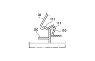
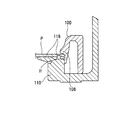
- the grommet disclosed in Japanese Patent Application Laid-Open No. 2003-319535 has a configuration shown in FIGS. 7A and 7B in order to prevent the grommet body that is in close contact with the resin inner from being turned up. That is, the first to third protrusions 102 to 104 are provided on the base-shaped peripheral edge 101 of the resin inner 100, while the first to third protrusions 102 to 104 are provided in the groove 111 covering the peripheral edge 101 on the grommet body 110. A close contact portion 112 having a width to be wrapped is provided.
- the groove 111 provided in the grommet body 110 includes the base-like peripheral portion 101 of the resin inner 100 and the first to third protrusions 102 to 104 protruding from the outer peripheral surface of the peripheral portion 101. It is only housed. Therefore, as shown in FIG. 8, when the lower interference member 120 is caught by the side end surface 113 constituting the groove 111 of the grommet main body 110 and pulled, the grommet main body 110 is turned over, and the base-like peripheral portion 101 of the resin inner 100 is turned. Therefore, the grommet main body 110 comes off.
- the grommet composed of the grommet main body 110 and the resin inner 100 is pressed against the one surface side of the vehicle body panel P when the engagement portion 108 of the resin inner 100 is attached to the through hole H of the vehicle body panel P.
- a rib 118 provided on the peripheral edge of the grommet body 110 is pressed against and fixed to the other surface side of the vehicle body panel P, thereby preventing water stoppage. Therefore, if the resin inner 100 is detached from the grommet main body 110, the resin inner 100 and the grommet main body 110 cannot be pressed against both surfaces of the vehicle body panel P, and the water stop performance cannot be maintained.
- the present invention has been made in view of the above problems, and it is an object of the present invention to ensure the waterproof performance of the grommet by preventing the base-like peripheral portion of the resin inner from being detached from the grommet body.
- the present invention provides a two-piece grommet comprising a grommet body made of an elastic body and a resin inner made of a resin molded product.
- Four locking parts for locking the vehicle body are provided at intervals on the outer peripheral surface of the cylindrical portion of the resin inner, and a pedestal portion is provided on the base end side of the cylindrical portion, and is protruded from the pedestal portion at an acute angle.
- the protruding portion protruding from the base portion of the resin inner is not only simply inserted and held in the insertion groove of the flange portion of the grommet body, but the tip of the protruding portion is connected to the outer peripheral wall of the tip of the insertion groove. I'm eating inside. In this way, when the tip of the projection is bitten into the inner surface of the outer peripheral wall of the tip of the insertion groove and fixed so as to pull the collar of the grommet body, the collar of the grommet body and the base portion of the resin inner are firmly fixed. be able to.
- the cylindrical portion of the inner resin has an oval or elliptical cross section, and a locking portion for locking the vehicle body is provided at each of the central portion on the long axis side and the central portion on the short axis side.
- the pedestal portion protrudes from the outer periphery on the base side, and the pedestal portion is divided across the lock portion on the short shaft side, and the protruding portion is protruded from the outer periphery of the divided pedestal portion.
- the pedestal portion of the resin inner has a long side portion facing the short axis side being continuous, and a notch hole is provided in the pedestal portion at a position facing the lock portion on the long side side.
- the short side facing the long axis is divided without providing a pedestal at a position corresponding to the lock.
- the protruding portion protrudes from the outer periphery of the divided end of the divided pedestal portion on both sides of the lock portion toward the outer periphery. That is, two protrusions are provided on each major axis side, and a total of four protrusions are provided.
- the grommet main body made of an elastic body such as rubber or elastomer to which the resin inner is assembled includes a small-diameter cylindrical portion that is in close contact with the wire group of the wire harness, and an oval shape that continuously expands from one end of the small-diameter cylindrical portion or An ellipse-shaped large-diameter cylindrical portion is provided, and the collar portion having an annular U-shaped cross section is provided on the outer periphery of the distal end of the large-diameter cylindrical portion.
- One side wall of the flange portion is continuous from the outer periphery of the large-diameter cylindrical portion, and the distal end side is folded to provide the distal end outer peripheral wall, and has a U-shaped cross section provided with another side wall facing the one side wall, The annular insertion groove is provided inside.
- a first seal lip projects from the other side wall, and a second seal lip is provided on the outer periphery of the first seal lip to serve as a pressure contact portion to the vehicle body panel.
- a protrusion is provided from the pedestal portion on the long axis side of the resin inner, the protrusion is positioned at a position farthest from the center of the resin inner, and the tips of these protrusions are the tips of the flanges of the grommet body. It bites into the inner surface of the outer peripheral wall. Thereby, the collar part of a grommet main body is most strongly pulled and fixed by the projection part of a base part. Therefore, even if a load is applied to the buttock by the external interference material, it is possible to prevent the buttock from being beaten.
- the projecting portion may be provided also from the pedestal portion on the short axis side to bite into the inner surface of the distal end side wall of the collar portion of the grommet body. Even if the protruding portion protrudes only from the pedestal portion on the short axis side and bites into the flange portion, the flange portion is made of an elastic body. Therefore, it is preferable to provide a protrusion on the long axis side as described above.
- a protrusion is provided on the base portion of the resin inner, and the protrusion is inserted into the insertion groove of the flange of the grommet main body.
- the tip of the protrusion is bitten into the inner surface of the outer peripheral wall of the tip of the flange, the fixing force between the flange of the grommet body and the base portion of the resin inner can be increased.
- a grommet to be installed in an oval or oval through hole in a vehicle body panel when the projection is provided on the pedestal portion on the long axis side, the pedestal portion and the projection portion are inserted in the insertion groove of the collar portion.
- the buttock can be pulled most strongly and assembled, and the pedestal can be more easily removed from the buttock.
- the collar does not come off the protrusion of the pedestal, preventing the resin inner from coming off the grommet body and preventing water stoppage performance from deteriorating. it can.
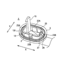
- FIG. 1 It is a perspective view which shows the grommet of embodiment of this invention.
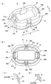
- the resin inner is shown
- (A) is a perspective view
- (B) is a plan view
- (C) and (D) are sectional views of the lock portion.
- a grommet main body is shown
- (A) is a perspective view
- (B) is sectional drawing.
- (A) is an expanded sectional view which shows the fixing
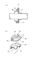
- (B) is a top view. It is sectional drawing which shows the state which attached the wire harness to the grommet. It is sectional drawing of the state which attached the grommet to the through-hole of the vehicle body panel.
- (B) is drawing of a prior art example. It is explanatory drawing which shows a problem. It is drawing which shows the state which attached the grommet to the through-hole of the vehicle body panel.
- a grommet 1 shown in FIG. 1 is a two-piece grommet including a resin inner 2 made of a resin molded product shown in FIG. 2 and a grommet body 3 made of a rubber molded product shown in FIG. As shown in FIG. 6, the grommet 1 is attached to a wire harness W / H arranged in an automobile, and is attached to an oval through hole H of the vehicle body panel P for waterproofing.
- the grommet body 3 shown in FIG. 3 includes a small-diameter cylindrical portion 11 that is in close contact with the outer periphery of the wire group of the wire harness W / H, and a large-diameter cylinder that continuously expands from one end of the small-diameter cylindrical portion 11 into an elliptical shape.
- the small-diameter cylindrical portion 11 is bent with respect to the axial direction of the large-diameter cylindrical portion 12.
- An annular flange 13 is provided on the outer periphery of the large-diameter cylindrical portion 12 of the grommet body 3, and the flange 13 has a bag shape with a U-shaped cross section.
- the flange 13 has one side wall 13a continuous from the small-diameter cylindrical portion 11, bent at the tip end side to provide a tip outer peripheral wall 13b, and is folded at the other end of the tip outer peripheral wall 13b to face the one side wall 13a. 13c is provided.
- a hollow portion surrounded by the one side wall 13a, the distal end outer peripheral wall 13b, and the other side wall 13c serves as an insertion groove 13d for a base of the resin inner 2 described later.
- the distal end outer peripheral wall 13b of the flange 13 is not provided with a protruding part, and has an oval shape.
- the other side wall 13c of the flange 13 is provided with a first seal lip 13e that presses against the vehicle body panel P, and a second seal lip 13f that presses against the vehicle body panel P protrudes from the outer periphery of the seal lip 13e.
- a tape winding tongue 15 is provided projecting from the inner periphery of the large diameter cylindrical portion 12 for tape winding and fixing with the wire harness W / H.
- the resin inner 2 has a cylindrical portion 20 having an oval cross section similar to the large-diameter cylindrical portion 12 of the grommet main body 3 and a base on the outer periphery of the base portion side (attachment side to the grommet main body 3) of the cylindrical portion 20.
- a portion 21 is provided in a protruding manner.
- the cylindrical portion 20 is provided with locking portions 22A and 22B for locking the vehicle body at the central portion on the opposite long axis side X, and locking portions 23A for locking the vehicle body at the central portion on the short shaft side Y, respectively. 23B is provided.
- the short shaft side Y lock portions 23A and 23B are in a frame shape as shown in the figure, and the tips of both side frames 27 are made continuous with the outer peripheral surface of the cylindrical portion 20, and as shown in FIG.
- the leading ends are connected by a connecting frame 28, and a protruding portion 29 for pressure contact with the vehicle body is provided on the connecting frame 28, and a locking claw 30 is provided protruding from the base portion of the protruding portion 29.
- the lock portions 22A and 22B on the long shaft side X are not frame-shaped, but as shown in FIG. 2D, the locking claws 32 are formed from the outer peripheral surface of the cylindrical portion 20 from the proximal end side of the protruding portion 31 for vehicle body pressure contact. Is protruding.
- the pedestal portion 21 is continuous on the long axis side X, and is provided with cutout holes 24A and 24B in portions facing the lower portions of the lock portions 22A and 22B.
- the projections 25A and 25B, 26A and 26B which are divided with the lock portions 23A and 23B interposed therebetween and projecting the tips from the outer peripheries of the divided base portions 21a and 21b at an acute angle, are projected.
- the base portion 21 of the resin inner 2 is provided with a total of four projecting portions protruding from both ends on the long axis side X.
- the assembly of the resin inner 2 and the grommet main body 3 is performed by inserting the base 21 of the resin inner 2 into the insertion groove 13d of the flange 13 of the grommet main body 3 as shown in FIG.
- the outer peripheral surface of the pedestal portion 21 is set so as to contact the inner surface of the distal end outer peripheral wall 13b of the flange portion 13. Therefore, the protrusions 25A, 25B, 26A, and 26B protruding from the pedestal portion 21 bite into the inner surface of the distal end outer peripheral wall 13b of the flange portion 13.
- the bite can be caused to bite from the inner surface of the tip outer peripheral wall 13b without difficulty because the tips of the projections 25A to 26B are projected at an acute angle.
- the collar part 13 of the grommet body 3 On the side of the collar part 13 of the grommet body 3, the collar part 13 is pressed outward by the protrusions 25 ⁇ / b> A to 26 ⁇ / b> B, and the collar part 13 is pressed outward in the direction away from each other on both sides of the long axis side X. Is firmly fixed to the pedestal 21 while being pulled to both sides. In addition, since both ends of the long axis side X are located farthest from the center axis of the resin inner 2, the collar portion 13 is pulled most strongly. As a result, the outer peripheral wall 13b at the tip of the flange 13 of the grommet body 3 can be most tightly fixed to the protrusions 25A to 26B of the base 21 of the resin inner 2.
- the cylindrical portion 20 provided with the lock portions 22A, 22B, 23A, 23B of the resin inner 2 has a large diameter of the grommet main body 3. Projecting from the large-diameter end of the cylindrical portion 12, the lock portions 22A to 23B are exposed on the outer surface.
- the wire group of the wire harness W / H is passed through the grommet 1 having the above-described configuration. Specifically, as shown in FIG. 5, the wire harness W / H is penetrated from the small-diameter cylindrical portion 11 to the large-diameter cylindrical portion 12 of the grommet body 3, and the resin inner 2 is further penetrated. The wire harness W / H is wound around the piece 15 with the tape T and fixed.
- the grommet 1 is attached to the through hole H of the vehicle body panel P as shown in FIG. 6 with the grommet 1 attached to the wire harness W / H.
- the locking claws 30 of the lock portions 23A and 23B of the resin inner 2 and the locking claws 32 of the lock portions 22A and 22B are locked to the inner peripheral surface of the through hole H.
- the base body pressure-contact parts 29 and 31 of the base part are in pressure contact with one surface side of the body panel P.
- the first seal lip 13e and the second seal lip 13f of the grommet body 3 are in pressure contact with the other surface side of the vehicle body panel P.
- the vehicle body pressure contact portions 29 and 31 of the resin inner 2 are pressed against one surface of the vehicle body panel P at the periphery of the through hole H, and the first seal lip 13e and the second seal lip 13f of the grommet body 3 are pressed against the other surface. Water is prevented from being generated through the through hole H.
- the grommets of the examples of the present invention had about 45% higher holding force than the conventional comparative grommets.
- the grommet of the present invention has a holding power of about 35% higher than that of the conventional grommet.
- the grommet of the present invention has a holding power of about 10% higher than that of the conventional grommet.
- the present invention is not limited to the above embodiment, and a protrusion may be provided on the short axis side of the base portion of the resin inner.
Landscapes
- Engineering & Computer Science (AREA)
- Mechanical Engineering (AREA)
- Installation Of Indoor Wiring (AREA)
- Insulating Bodies (AREA)
Abstract
グロメット本体に樹脂インナーを組みつけた二体物のグロメットにおいて、樹脂インナーが外れないようにする。樹脂インナー2の筒部の外周面に間隔をあけて4つの車体係止用のロック部22A~23Bを設けるとともに、該筒部の基端側に台座部21を設け、該台座部から鋭角状に突出させた突起部25A~26Bを備える一方、グロメット本体3の筒部から台座部21の挿入溝13dを設けた鍔部13を設け、グロメット本体の鍔部の挿入溝に挿入した樹脂インナーの台座部の突起部の先端を、鍔部13の挿入溝の先端外周壁13bの内面に食い込ませて固定している。
Description
本発明はグロメットに関し、詳しくは、車両に配索されるワイヤハーネスに取り付け、車体パネルの貫通穴に装着して防水、防塵を図るグロメットに関し、弾性材からなるグロメット本体と、樹脂成形品からなる樹脂インナーとからなり、該樹脂インナーに設けた係止爪を前記貫通穴に係止する二体物のグロメットにおいて、外部干渉材で樹脂インナーの係止が外れないようにするものである。
従来、この種の二体物グロメットについて種々の提案がなされている。例えば、特開2003-319535号公報に開示されたグロメットでは、樹脂インナーに密着させているグロメット本体がめくれるのを防止するため、図7(A)(B)に示す構成とされている。即ち、樹脂インナー100の台座状の周縁部101に第1~第3突起102~104を設ける一方、グロメット本体110には前記周縁部101を覆う溝部111に第1~第3突起102~104をラップさせる幅を有する密着部112を設けている。
前記特許文献1の構成としても、グロメット本体110に設けた溝部111に樹脂インナー100の台座状の周縁部101および該周縁部101の外周面から突設した第1~第3突起102~104を収容しているだけである。よって、図8に示すように、グロメット本体110の溝111を構成する側部端面113に下部干渉材120が引っ掛かって引っ張られると、グロメット本体110がめくれ、樹脂インナー100の台座状の周縁部101からグロメット本体110が外れることとなる。
前記グロメット本体110と樹脂インナー100とからなるグロメットは、図9に示すように、車体パネルPの貫通穴Hに装着時に、樹脂インナー100の係止部108が車体パネルPの一面側に圧接すると共に、グロメット本体110の周縁部に設けたリブ118が車体パネルPの他面側に圧接して固定し、これにより止水を図っている。よって、樹脂インナー100がグロメット本体110から外れると、前記車体パネルPの両面への樹脂インナー100とグロメット本体110からの圧接ができず、止水性能を保持できない問題がある。
本発明は前記問題に鑑みてなされたもので、樹脂インナーの台座状の周縁部をグロメット本体から外れないようにして、グロメットの止水性能を確保することを課題としている。
前記課題を解決するため、本発明は、弾性体からなるグロメット本体と、樹脂成形品からなる樹脂インナーとからなる二体物のグロメットにおいて、
前記樹脂インナーの筒部の外周面に間隔をあけて4つの車体係止用のロック部を設けるとともに、該筒部の基端側に台座部を設け、該台座部から鋭角状に突出させた突起部を備える一方、
前記グロメット本体の筒部から前記台座部の挿入溝を設けた鍔部を設け、
前記グロメット本体の鍔部の挿入溝に挿入した前記樹脂インナーの台座部の突起部の先端を、前記鍔部の挿入溝の先端外周壁の内面に食い込ませて固定していることを特徴とするグロメットを提供している。
前記樹脂インナーの筒部の外周面に間隔をあけて4つの車体係止用のロック部を設けるとともに、該筒部の基端側に台座部を設け、該台座部から鋭角状に突出させた突起部を備える一方、
前記グロメット本体の筒部から前記台座部の挿入溝を設けた鍔部を設け、
前記グロメット本体の鍔部の挿入溝に挿入した前記樹脂インナーの台座部の突起部の先端を、前記鍔部の挿入溝の先端外周壁の内面に食い込ませて固定していることを特徴とするグロメットを提供している。
前記のように、樹脂インナーの台座部から突出させた突起部をグロメット本体の鍔部の挿入溝内に単に挿入保持しているだけでなく、前記突起部の先端を挿入溝の先端外周壁の内面に食い込ませている。
このように、突起部の先端を挿入溝の先端外周壁の内面に食い込ませ、グロメット本体の鍔部を引っ張るように固定すると、グロメット本体の鍔部と樹脂インナーの台座部とを強固に固定することができる。
このように、突起部の先端を挿入溝の先端外周壁の内面に食い込ませ、グロメット本体の鍔部を引っ張るように固定すると、グロメット本体の鍔部と樹脂インナーの台座部とを強固に固定することができる。
本発明者の後述する実験によると、7~8Nの引張荷重を鍔部に負荷しても、鍔部が樹脂インナーの台座部から外れず、樹脂インナーに対するグロメット本体の保持力を、鍔部に台座を挿入しているだけの場合と比較して10%~50%程度増強することができた。
これにより、グロメット本体の鍔部に外部干渉材が引っ掛かり、鍔部をめくる方向に引張力が作用しても、鍔部がめくれにくくなり、鍔部から樹脂インナーの台座部が外れることを防止でき、グロメットの止水性能の信頼性を高めることができる。
これにより、グロメット本体の鍔部に外部干渉材が引っ掛かり、鍔部をめくる方向に引張力が作用しても、鍔部がめくれにくくなり、鍔部から樹脂インナーの台座部が外れることを防止でき、グロメットの止水性能の信頼性を高めることができる。
前記樹脂インナーの前記筒部は断面長円形状または楕円形状とし、長軸側の中央部と短軸側の中央部にそれぞれ前記車体係止用のロック部を設けている一方、該筒部の基部側の外周より前記台座部を突設し、かつ、該台座部は前記短軸側のロック部を挟んで分断し、該分断した台座部の外周より前記突起部を突設している。
前記樹脂インナーの台座部は、短軸側で対向する長辺部は連続させ、該長辺側の前記ロック部と対向する位置の台座部に切欠穴を設けている。一方、長軸側で対向する短辺側には前記ロック部と対応する位置に台座部を設けずに分断している。このロック部の両側の分断された台座部の分割端の外周より前記突起部を外周に向けて突設している。即ち、各長軸側に2個の突起部を設け、合計4個の突起部を設けている。
前記樹脂インナーを組みつけるゴムまたはエラストマー等の弾性体からなる前記グロメット本体は、ワイヤハーネスの電線群に密着させる小径筒部と、該小径筒部の一端より連続して拡径する長円形状または楕円形状の大径筒部を備え、該大径筒部の先端外周に環状の断面コ字形状とした前記鍔部を備えている。該鍔部の一側壁は前記大径筒部の外周から連続し、前記先端側を折り返して前記先端外周壁を設けると共に、前記一側壁と対向する他側壁を設けた断面コ字形状とし、その内部に環状の前記挿入溝を設けている。また、前記他側壁に第1シールリップを突設すると共に該第1シールリップの外周に第2シールリップを設け、車体パネルへの圧接部としている。
前記のように、樹脂インナーの長軸側に台座部より突起部を設け、該突起部を樹脂インナーの中心より最も離れた箇所に位置させ、これら突起部の先端をグロメット本体の鍔部の先端外周壁の内面に食い込ませている。これにより、グロメット本体の鍔部が台座部の突起部により最も強く引っ張られて固定される。よって、外部干渉材により鍔部に負荷がかかっても、鍔部を捲れないようにすることができる。
また、短軸側の台座部からも前記突起部を設けてグロメット本体の鍔部の先端側壁の内面に食い込ませても良い。
なお、短軸側の台座部からのみ前記突起部を突出させて鍔部に食い込ませても、鍔部が弾性体からなるため、長軸側から鍔部が寄ってきて、鍔部を突起部により強く引っ張れないため、前記のように長軸側に突起部を設けることが好ましい。
また、短軸側の台座部からも前記突起部を設けてグロメット本体の鍔部の先端側壁の内面に食い込ませても良い。
なお、短軸側の台座部からのみ前記突起部を突出させて鍔部に食い込ませても、鍔部が弾性体からなるため、長軸側から鍔部が寄ってきて、鍔部を突起部により強く引っ張れないため、前記のように長軸側に突起部を設けることが好ましい。
上述したように、本発明の弾性体からなるグロメット本体と樹脂インナーとの2体物グロメットにおいて、樹脂インナーの台座部に突起部を設け、該突起部をグロメット本体の鍔部の挿入溝に挿入した状態で、突起部の先端を鍔部の先端外周壁の内面に食い込ませているため、グロメット本体の鍔部と樹脂インナーの台座部との固定力を増強することができる。
特に、車体パネルの楕円状あるいは長円状の貫通穴に装着するグロメットにおいて、長軸側の台座部に前記突起部を設けると、台座部および突起部を鍔部の挿入溝に挿入した状態で鍔部を最も強く引っ張って組みつけることができ、その分、鍔部より台座部を外れにくくできる。その結果、外部干渉材により鍔部に捲れ方向の負荷が作用しても、鍔部は台座部の突起部からははなれず、グロメット本体から樹脂インナーが外れて止水性能が低下することを防止できる。
以下、本発明のグロメットの実施形態を図面を参照して説明する。
図1に示すグロメット1は、図2に示す樹脂成形品からなる樹脂インナー2と、図3に示すゴム成形品からなるグロメット本体3とからなる二体物のグロメットである。
該グロメット1は、図6に示すように、自動車に配索するワイヤハーネスW/Hに取り付け、車体パネルPの長円形状の貫通穴Hに装着して防水を図るものである。
図1に示すグロメット1は、図2に示す樹脂成形品からなる樹脂インナー2と、図3に示すゴム成形品からなるグロメット本体3とからなる二体物のグロメットである。
該グロメット1は、図6に示すように、自動車に配索するワイヤハーネスW/Hに取り付け、車体パネルPの長円形状の貫通穴Hに装着して防水を図るものである。
前記図3に示すグロメット本体3は、ワイヤハーネスW/Hの電線群の外周に密着させる小径筒部11と、該小径筒部11の一端より連続して長円形状に拡径する大径筒部12を備え、該大径筒部12の軸線方向に対して小径筒部11を屈曲させている。
グロメット本体3の大径筒部12の外周に環状の鍔部13を設け、該鍔部13は断面コ字形状の袋状としている。該鍔部13は一側壁13aを小径筒部11から連続させ、先端側を屈曲させて先端外周壁13bを設け、該先端外周壁13bの他端を折り返して前記一側壁13aと対向する他側壁13cを設けている。該一側壁13a、先端外周壁13b、他側壁13cで囲まれた中空部を後述する樹脂インナー2の台座の挿入溝13dとしている。該鍔部13の先端外周壁13bは部分的に突出部を設けておらず、長円形状としている。
前記鍔部13の他側壁13cには車体パネルPに圧接する第1シールリップ13eを設け、かつ、該シールリップ13eの外周に車体パネルPに圧接する第2シールリップ13fを突設している。
また、大径筒部12の内周よりワイヤハーネスW/Hとのテープ巻き固着するためのテープ巻用舌片15を突設している。
前記鍔部13の他側壁13cには車体パネルPに圧接する第1シールリップ13eを設け、かつ、該シールリップ13eの外周に車体パネルPに圧接する第2シールリップ13fを突設している。
また、大径筒部12の内周よりワイヤハーネスW/Hとのテープ巻き固着するためのテープ巻用舌片15を突設している。
前記樹脂インナー2は、前記グロメット本体3の大径筒部12と相似状の断面長円形状の筒部20と、該筒部20の基部側(グロメット本体3への取付側)の外周に台座部21を突設している。
前記筒部20には、その対向する長軸側Xの中央部に車体係止用のロック部22A、22Bを設けると共に、短軸側Yの中央部にそれぞれ車体係止用のロック部23A、23Bを設けている。
前記筒部20には、その対向する長軸側Xの中央部に車体係止用のロック部22A、22Bを設けると共に、短軸側Yの中央部にそれぞれ車体係止用のロック部23A、23Bを設けている。
前記短軸側Yのロック部23A、23Bは、図示のように枠状で、両側枠27の先端を筒部20の外周面に連続させ、図2(C)に示すように両側枠27の先端を連結枠28で連結し、該連結枠28に車体圧接用の突出部29を設けると共に、該突出部29の基部から係止爪30を突設している。長軸側Xのロック部22A、22Bは、枠状ではなく、図2(D)に示すように、筒部20の外周面から車体圧接用の突出部31の基端側から係止爪32を突設している。
前記台座部21は長軸側Xは連続し、ロック部22A、22Bの下方に対向する部分には切欠穴24A、24Bを設けている。
一方、短軸側Yでは、ロック部23A、23Bを挟んで分断し、該分断した台座部21a、21bの外周より先端を鋭角状に突出させた突起部25Aと25B、26Aと26Bとを突設している。このように、樹脂インナー2の台座部21には長軸側Xの両端に各一対、合計4個の突起部を突設している。
一方、短軸側Yでは、ロック部23A、23Bを挟んで分断し、該分断した台座部21a、21bの外周より先端を鋭角状に突出させた突起部25Aと25B、26Aと26Bとを突設している。このように、樹脂インナー2の台座部21には長軸側Xの両端に各一対、合計4個の突起部を突設している。
前記樹脂インナー2とグロメット本体3との組み付けは、図4に示すように、グロメット本体3の鍔部13の挿入溝13dに樹脂インナー2の台座部21を挿入して行っている。その際、台座部21の外周面が鍔部13の先端外周壁13bの内面に当接するように設定している。よって、台座部21より突出する突起部25A、25B、26A、26Bは、鍔部13の先端外周壁13bの内面に食い込むこととなる。該食い込みは前記突起部25A~26Bの先端を鋭角状に突出させているため、無理なく先端外周壁13bの内面から食い込ませることができる。
グロメット本体3の鍔部13側では、突起部25A~26Bにより外方へと押圧され、長軸側Xの両側で鍔部13が互いに離れる方向の外方へ押圧されることにより、鍔部13は両側へ引っ張られた状態で台座部21に強く固定される。かつ、該長軸側Xの両端は樹脂インナー2の中心軸芯より最も離れた位置にあるため、鍔部13を最も強く引っ張ることとなる。それにより、グロメット本体3の鍔部13の先端外周壁13bを樹脂インナー2の台座部21の突起部25A~26Bに最も強く密着固定することができる。
このように、樹脂インナー2をグロメット本体3に固定した状態で、図1に示すように、樹脂インナー2のロック部22A、22B、23A、23Bを設けた筒部20はグロメット本体3の大径筒部12の大径側先端より突出し、前記ロック部22A~23Bは外面に露出している。
前記構成からなるグロメット1にワイヤハーネスW/Hの電線群を貫通させている。具体的には、図5に示すように、グロメット本体3の小径筒部11から大径筒部12へとワイヤハーネスW/Hを貫通させ、さらに、樹脂インナー2を貫通させ、前記テープ巻き舌片15にワイヤハーネスW/HをテープTで巻き付けて固着している。
前記のように、グロメット1をワイヤハーネスW/Hに取り付けた状態で、図6に示すように、車体パネルPの貫通穴Hに装着している。
該装着状態では、樹脂インナー2のロック部23A、23Bの係止爪30およびロック部22A、22Bの係止爪32が貫通穴Hの内周面に係止し、これら係止爪30、32の基部の車体圧接部29、31が車体パネルPの一面側に圧接する。該車体パネルPの他面側にはグロメット本体3の第1シールリップ13e、第2シールリップ13fが圧接する。
このように貫通穴Hの周縁で車体パネルPの一面を樹脂インナー2の車体圧接部29、31、他面をグロメット本体3の第1シールリップ13e、第2シールリップ13fが圧接することにより、貫通穴Hを通して浸水が発生するのを防止している。
該装着状態では、樹脂インナー2のロック部23A、23Bの係止爪30およびロック部22A、22Bの係止爪32が貫通穴Hの内周面に係止し、これら係止爪30、32の基部の車体圧接部29、31が車体パネルPの一面側に圧接する。該車体パネルPの他面側にはグロメット本体3の第1シールリップ13e、第2シールリップ13fが圧接する。
このように貫通穴Hの周縁で車体パネルPの一面を樹脂インナー2の車体圧接部29、31、他面をグロメット本体3の第1シールリップ13e、第2シールリップ13fが圧接することにより、貫通穴Hを通して浸水が発生するのを防止している。
前記のように車体パネルPの貫通穴Hに装着したグロメット1の鍔部13に、捲れるように外部干渉材が作用しても、鍔部13の先端外周壁13bに樹脂インナー2の台座21から突設した4つの突起部25A~26Bの先端を食い込ませて、強固に固着しているため、鍔部13に捲れが発生するのを防止できる。その結果、グロメット本体3と樹脂インナー2とが外れるのを防止でき、グロメット1の貫通穴Hへの固定および、グロメット1の止水性能を信頼性の高いものとすることができる。
「実験例」
前記実施形態のグロメットと、樹脂インナーに前記突起部を設けていない従来品のグロメットとに、図4(B)に示すように、長軸側X(1)、短軸側Y(2)、XとYの中間位置(3)に、鍔部が捲れるまで引っ張り荷重を負荷した実験を行った。
その結果を下記の表1に示す。
前記実施形態のグロメットと、樹脂インナーに前記突起部を設けていない従来品のグロメットとに、図4(B)に示すように、長軸側X(1)、短軸側Y(2)、XとYの中間位置(3)に、鍔部が捲れるまで引っ張り荷重を負荷した実験を行った。
その結果を下記の表1に示す。

表1に示すように、長軸側(1)の方向への引っ張り荷重に対して、本発明の実施例のグロメットは従来品の比較例グロメットより約45%の保持力がアップしていた。
短軸側(2)の方向への引っ張り荷重に対して、本発明のグロメットは従来品のグロメットより約35%の保持力がアップしていた。
前記(3)の方向への引っ張り荷重に対して、本発明のグロメットは従来品のグロメットより約10%の保持力がアップしていた。
このように、台座部に突起部を設け、該突起部を鍔部の先端外周壁の内面に食い込ませると、鍔部に対していずれの方向からの引張負荷に対して保持力がアップし、樹脂インナーがグロメット本体から外れにくいことが確認できた。
短軸側(2)の方向への引っ張り荷重に対して、本発明のグロメットは従来品のグロメットより約35%の保持力がアップしていた。
前記(3)の方向への引っ張り荷重に対して、本発明のグロメットは従来品のグロメットより約10%の保持力がアップしていた。
このように、台座部に突起部を設け、該突起部を鍔部の先端外周壁の内面に食い込ませると、鍔部に対していずれの方向からの引張負荷に対して保持力がアップし、樹脂インナーがグロメット本体から外れにくいことが確認できた。
本発明は前記実施形態に限定されず、樹脂インナーの台座部の短軸側にも突起部を設けてもよい。
1 グロメット
2 樹脂インナー
3 グロメット本体
12 大径筒部
13 鍔部
13b 先端外周壁
13d 挿入溝
20 筒部
21 台座部
22A、22B、23A、23B ロック部
25A、25B、26A、26B 突起部
W/H ワイヤハーネス
H 貫通穴
P 車体パネル
X 長軸方向
Y 短軸方向
2 樹脂インナー
3 グロメット本体
12 大径筒部
13 鍔部
13b 先端外周壁
13d 挿入溝
20 筒部
21 台座部
22A、22B、23A、23B ロック部
25A、25B、26A、26B 突起部
W/H ワイヤハーネス
H 貫通穴
P 車体パネル
X 長軸方向
Y 短軸方向
Claims (2)
- 弾性体からなるグロメット本体と、樹脂成形品からなる樹脂インナーとからなる二体物のグロメットにおいて、
前記樹脂インナーの筒部の外周面に間隔をあけて4つの車体係止用のロック部を設けるとともに、該筒部の基端側に台座部を設け、該台座部から鋭角状に突出させた突起部を備える一方、
前記グロメット本体の筒部から前記台座部の挿入溝を設けた鍔部を設け、
前記グロメット本体の鍔部の挿入溝に挿入した前記樹脂インナーの台座部の突起部の先端を、前記鍔部の挿入溝の先端外周壁の内面に食い込ませて固定していることを特徴とするグロメット。 - 前記樹脂インナーの前記筒部は断面長円形状または楕円形状とし、長軸側の中央部と短軸側の中央部にそれぞれ前記車体係止用のロック部を設けている一方、該筒部の基部側の外周より前記台座部を突設し、かつ、該台座部は前記短軸側のロック部を挟んで分断し、該分断した台座部の外周より前記突起部を突設している請求項1に記載のグロメット。
Applications Claiming Priority (2)
| Application Number | Priority Date | Filing Date | Title |
|---|---|---|---|
| JP2008-284831 | 2008-11-05 | ||
| JP2008284831A JP2010114992A (ja) | 2008-11-05 | 2008-11-05 | グロメット |
Publications (1)
| Publication Number | Publication Date |
|---|---|
| WO2010053067A1 true WO2010053067A1 (ja) | 2010-05-14 |
Family
ID=42152875
Family Applications (1)
| Application Number | Title | Priority Date | Filing Date |
|---|---|---|---|
| PCT/JP2009/068760 Ceased WO2010053067A1 (ja) | 2008-11-05 | 2009-11-02 | グロメット |
Country Status (2)
| Country | Link |
|---|---|
| JP (1) | JP2010114992A (ja) |
| WO (1) | WO2010053067A1 (ja) |
Cited By (1)
| Publication number | Priority date | Publication date | Assignee | Title |
|---|---|---|---|---|
| US12347587B2 (en) * | 2022-06-15 | 2025-07-01 | Yazaki Corporation | Grommet assembly and wire harness |
Citations (2)
| Publication number | Priority date | Publication date | Assignee | Title |
|---|---|---|---|---|
| JP2005073349A (ja) * | 2003-08-22 | 2005-03-17 | Sumitomo Wiring Syst Ltd | インナー付きグロメット |
| JP2008218110A (ja) * | 2007-03-01 | 2008-09-18 | Sumitomo Wiring Syst Ltd | ワイヤハーネス用グロメット |
-
2008
- 2008-11-05 JP JP2008284831A patent/JP2010114992A/ja not_active Withdrawn
-
2009
- 2009-11-02 WO PCT/JP2009/068760 patent/WO2010053067A1/ja not_active Ceased
Patent Citations (2)
| Publication number | Priority date | Publication date | Assignee | Title |
|---|---|---|---|---|
| JP2005073349A (ja) * | 2003-08-22 | 2005-03-17 | Sumitomo Wiring Syst Ltd | インナー付きグロメット |
| JP2008218110A (ja) * | 2007-03-01 | 2008-09-18 | Sumitomo Wiring Syst Ltd | ワイヤハーネス用グロメット |
Cited By (1)
| Publication number | Priority date | Publication date | Assignee | Title |
|---|---|---|---|---|
| US12347587B2 (en) * | 2022-06-15 | 2025-07-01 | Yazaki Corporation | Grommet assembly and wire harness |
Also Published As
| Publication number | Publication date |
|---|---|
| JP2010114992A (ja) | 2010-05-20 |
Similar Documents
| Publication | Publication Date | Title |
|---|---|---|
| JP5772444B2 (ja) | クランプ | |
| JP5387541B2 (ja) | グロメット | |
| JPH10294146A (ja) | ゴムブーツ | |
| US9825397B2 (en) | Grommet-equipped connector and connector | |
| JP6752256B2 (ja) | インナー付きグロメット | |
| JP6752257B2 (ja) | インナー付きグロメット | |
| JP2020036478A (ja) | グロメット | |
| JP5477221B2 (ja) | ワイヤハーネス用のグロメット | |
| JP4003426B2 (ja) | 樹脂インナー付きグロメット | |
| JP2010283935A (ja) | ワイヤハーネスとプロテクタの取付構造 | |
| JPH09112699A (ja) | シール部材の取付け構造 | |
| JP7181258B2 (ja) | ワイヤハーネス及びグロメット外れ防止構造 | |
| JP2010114992A (ja) | グロメット | |
| JP2596427Y2 (ja) | クランプ | |
| JP7235570B2 (ja) | クランプ | |
| WO2012127721A1 (ja) | ワイヤーハーネスの保護具 | |
| JP2010213426A (ja) | ワイヤハーネス用クランプ | |
| JP2006073478A (ja) | 防水コネクタ | |
| JP2019088155A (ja) | グロメットおよびグロメット取付構造 | |
| JPH0619899Y2 (ja) | グロメット | |
| JP4444916B2 (ja) | 電気接続箱へのグロメット取付構造 | |
| JPH11273481A (ja) | ケーブルブッシュ | |
| JP5761165B2 (ja) | グロメット | |
| JP2001258138A (ja) | クランプの車体固定構造 | |
| JP2017158362A (ja) | グロメット及びグロメット付ワイヤーハーネス |
Legal Events
| Date | Code | Title | Description |
|---|---|---|---|
| 121 | Ep: the epo has been informed by wipo that ep was designated in this application |
Ref document number: 09824766 Country of ref document: EP Kind code of ref document: A1 |
|
| NENP | Non-entry into the national phase |
Ref country code: DE |
|
| 122 | Ep: pct application non-entry in european phase |
Ref document number: 09824766 Country of ref document: EP Kind code of ref document: A1 |