WO2010050487A1 - 無線通信システム、無線端末及び通信制御方法 - Google Patents
無線通信システム、無線端末及び通信制御方法 Download PDFInfo
- Publication number
- WO2010050487A1 WO2010050487A1 PCT/JP2009/068453 JP2009068453W WO2010050487A1 WO 2010050487 A1 WO2010050487 A1 WO 2010050487A1 JP 2009068453 W JP2009068453 W JP 2009068453W WO 2010050487 A1 WO2010050487 A1 WO 2010050487A1
- Authority
- WO
- WIPO (PCT)
- Prior art keywords
- base station
- power
- request
- transmission power
- radio base
- Prior art date
- Legal status (The legal status is an assumption and is not a legal conclusion. Google has not performed a legal analysis and makes no representation as to the accuracy of the status listed.)
- Ceased
Links
Images





Classifications
-
- H—ELECTRICITY
- H04—ELECTRIC COMMUNICATION TECHNIQUE
- H04W—WIRELESS COMMUNICATION NETWORKS
- H04W52/00—Power management, e.g. Transmission Power Control [TPC] or power classes
- H04W52/04—Transmission power control [TPC]
- H04W52/18—TPC being performed according to specific parameters
- H04W52/24—TPC being performed according to specific parameters using SIR [Signal to Interference Ratio] or other wireless path parameters
- H04W52/243—TPC being performed according to specific parameters using SIR [Signal to Interference Ratio] or other wireless path parameters taking into account interferences
-
- H—ELECTRICITY
- H04—ELECTRIC COMMUNICATION TECHNIQUE
- H04W—WIRELESS COMMUNICATION NETWORKS
- H04W52/00—Power management, e.g. Transmission Power Control [TPC] or power classes
- H04W52/04—Transmission power control [TPC]
- H04W52/18—TPC being performed according to specific parameters
- H04W52/26—TPC being performed according to specific parameters using transmission rate or quality of service QoS [Quality of Service]
-
- H—ELECTRICITY
- H04—ELECTRIC COMMUNICATION TECHNIQUE
- H04W—WIRELESS COMMUNICATION NETWORKS
- H04W52/00—Power management, e.g. Transmission Power Control [TPC] or power classes
- H04W52/04—Transmission power control [TPC]
- H04W52/06—TPC algorithms
- H04W52/08—Closed loop power control
-
- H—ELECTRICITY
- H04—ELECTRIC COMMUNICATION TECHNIQUE
- H04W—WIRELESS COMMUNICATION NETWORKS
- H04W52/00—Power management, e.g. Transmission Power Control [TPC] or power classes
- H04W52/04—Transmission power control [TPC]
- H04W52/18—TPC being performed according to specific parameters
- H04W52/24—TPC being performed according to specific parameters using SIR [Signal to Interference Ratio] or other wireless path parameters
-
- H—ELECTRICITY
- H04—ELECTRIC COMMUNICATION TECHNIQUE
- H04W—WIRELESS COMMUNICATION NETWORKS
- H04W52/00—Power management, e.g. Transmission Power Control [TPC] or power classes
- H04W52/04—Transmission power control [TPC]
- H04W52/18—TPC being performed according to specific parameters
- H04W52/26—TPC being performed according to specific parameters using transmission rate or quality of service QoS [Quality of Service]
- H04W52/265—TPC being performed according to specific parameters using transmission rate or quality of service QoS [Quality of Service] taking into account the quality of service QoS
-
- H—ELECTRICITY
- H04—ELECTRIC COMMUNICATION TECHNIQUE
- H04W—WIRELESS COMMUNICATION NETWORKS
- H04W88/00—Devices specially adapted for wireless communication networks, e.g. terminals, base stations or access point devices
- H04W88/02—Terminal devices
Definitions
- the present invention relates to a radio communication system in which a radio terminal sets transmission power and a modulation scheme in response to a request from a radio base station, a radio terminal in the radio communication system, and a communication control method in the radio terminal.
- each wireless base station assigns a communication channel to a wireless terminal located in a cell provided by the wireless base station.
- the wireless terminal uses this assigned communication channel to connect to a wireless base station that provides a cell in the area and communicates with the wireless base station.
- the communication quality may be deteriorated when the transmission power set for the uplink communication channel by the mobile terminal is unchanged.
- the wireless base station measures the communication quality of the uplink communication channel assigned to the wireless terminal, When the communication quality is less than a predetermined level, the wireless terminal is requested to increase transmission power.
- LTE Long Termination Evolution
- 3GPP Third Generation Partnership Project
- a communication channel may be subject to interference from the other communication channel.
- the radio base station requests a reduction in transmission power from another radio terminal to which the communication channel causing the interference is assigned (for example, Patent Document 1). reference).
- a wireless terminal is a wireless base station (hereinafter referred to as a connected wireless base station) to which the wireless terminal is connected. ) From the wireless base station that is not the connection destination of the wireless terminal (hereinafter referred to as a non-connection destination wireless base station).
- an object of the present invention is to provide a wireless communication system, a wireless terminal, and a communication control method capable of appropriately performing both suppression of deterioration in communication quality and suppression of interference. .
- the first feature of the present invention is that a wireless terminal (wireless terminal 1A, wireless terminal 1B, wireless terminal 1C) and a connection-destination wireless base station that is a wireless base station to which the wireless terminal is connected (for wireless terminal 1A)
- a wireless communication system wireless communication system 10) including a base station 2B and a wireless base station 2C, a wireless base station 2B and a wireless base station 2C for the wireless terminal 1B, and a wireless base station 2A and a wireless base station 2B for the wireless terminal 1C).
- the connection-destination radio base station includes a communication quality measurement unit (CQI measurement unit 252 and CRC) that measures communication quality of an uplink communication channel in the connection-destination radio base station.
- a communication quality measurement unit CQI measurement unit 252 and CRC
- CQI measurement unit 252 and CRC measures communication quality of an uplink communication channel in the connection-destination radio base station.
- a request for increasing the power for requesting an increase in transmission power of the uplink communication channel is sent to the wireless terminal.
- a power increase request transmission unit transmission power / modulation method setting unit 260 and message transmission unit 262 for transmitting to the non-connection-destination radio base station through communication in the uplink communication channel.
- the uplink communication A power reduction request transmission unit (transmission power setting unit 274 and message) that transmits a power reduction request for requesting a reduction in channel transmission power to the wireless terminal.
- a power increase request receiving unit that receives the power increase request from the connected radio base station, and the power decrease request from the non-connected radio base station.
- the power reduction request receiving unit power reduction request receiving unit 202) that receives the power increase request is received by the power increase request receiving unit, and the power reduction request is received by the power reduction request receiving unit.
- a modulation class that combines transmission power and modulation method of the uplink communication channel with a transmission power lower than the immediately previous transmission power and a modulation method in which the communication quality of the uplink communication channel is equal to or higher than a required level.
- the gist is to include a modulation class setting unit (modulation class setting unit 208) to be set.
- the wireless terminal lowers the transmission power of the uplink communication channel in response to a request to reduce the transmission power by the non-connection destination wireless base station. Therefore, the interference power generated in the communication channel in the non-connected wireless base station is suppressed.
- the wireless terminal sets the modulation scheme of the uplink communication channel to a modulation scheme that allows the communication quality of the uplink communication channel to be a required level or higher. Therefore, the interference power generated in the communication channel in the non-connection destination radio base station is suppressed, and the deterioration of the communication quality of the uplink communication channel in the connection destination radio base station is suppressed.
- a second feature of the present invention is a wireless terminal that communicates with a wireless base station, and transmits the uplink communication channel transmission power transmitted from a connected wireless base station that is a connected wireless base station.
- a power reduction request receiving unit that receives a power reduction request for receiving, and when the power increase request is received by the power increase request receiving unit and the power reduction request is received by the power reduction request receiving unit.
- a transmission power lower than the previous transmission power is set and the communication quality of the uplink communication channel is required.
- a modulation class setting unit that sets a modulation scheme to be more bell.
- the wireless terminal lowers the transmission power of the uplink communication channel in response to a transmission power reduction request from the non-connected wireless base station.
- the radio terminal sets the modulation scheme of the uplink communication channel to a modulation scheme in which the communication quality of the uplink communication channel becomes a required level or higher. Therefore, the interference power generated in the communication channel in the non-connection destination radio base station is suppressed, and the deterioration of the communication quality of the uplink communication channel in the connection destination radio base station is suppressed.
- the power reduction request includes a transmission power value
- the modulation class setting unit sets transmission power corresponding to the transmission power value included in the power reduction request. Is the gist.
- the power reduction request receiving unit receives a plurality of the power reduction requests transmitted from each of the plurality of non-connected wireless base stations
- the modulation class setting unit includes a plurality of modulation class setting units The gist is to set transmission power corresponding to either the minimum value or the average value of the transmission power values included in the power reduction request.
- a modulation scheme request receiving unit (a power increase request / The modulation class request receiving unit 204) includes a modulation class setting unit that sets a modulation method corresponding to the modulation method request received by the power increase request receiving unit.
- the modulation class setting unit is configured to perform the communication when the communication quality of the uplink communication channel is less than the required level.
- the gist is to cancel the setting of the modulation scheme corresponding to the modulation scheme request.
- the wireless terminal in the modulation scheme requested by the connection destination radio base station, when the communication quality of the uplink communication channel is less than the required level, the deterioration of the communication quality of the uplink communication channel is suppressed. Therefore, the wireless terminal can appropriately suppress the deterioration of the communication quality of the uplink communication channel by canceling the setting of the modulation scheme required by the connection destination wireless base station.
- a seventh feature of the present invention includes a retransmission request receiving unit (power increase request / modulation method request receiving unit 204) that receives a retransmission request transmitted from the connected radio base station, and the modulation class setting unit includes: When the retransmission request is received by the retransmission request receiving unit, the gist is to set a transmission power higher than the previous transmission power only when transmitting a radio signal that is a target of the retransmission request.
- An eighth feature of the present invention is a communication control method in a wireless terminal that communicates with a wireless base station, wherein the wireless terminal is transmitted from a connected wireless base station that is a connected wireless base station.
- Receiving a power increase request for requesting an increase in transmission power of an uplink communication channel and the wireless terminal is transmitted from a non-connection destination radio base station that is a radio base station other than a connection destination, Receiving a power decrease request for requesting a decrease in transmission power of an uplink communication channel; and when the wireless terminal receives the power increase request and the power decrease request, transmission power of the uplink communication channel and A modulation method in which a transmission power lower than the previous transmission power is set for a modulation class combined with a modulation method, and the communication quality of the uplink communication channel is a required level or higher. And summarized in that and a step of setting.
- the wireless terminal lowers the transmission power of the uplink communication channel in response to a request to reduce the transmission power by the non-connected wireless base station, and sets the modulation method of the uplink communication channel to the communication of the uplink communication channel.
- the modulation method so that the quality exceeds the required level, the interference power generated in the communication channel in the non-connected radio base station is suppressed, and the deterioration in the communication quality of the uplink communication channel in the connected radio base station is also suppressed. Is done.
- FIG. 1 is an overall schematic configuration diagram of a radio communication system according to an embodiment of the present invention.
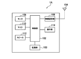
- FIG. 2 is a schematic configuration diagram of a radio terminal according to the embodiment of the present invention.
- FIG. 3 is a functional block configuration diagram of the control unit in the wireless terminal according to the embodiment of the present invention.
- FIG. 4 is a schematic configuration diagram of a radio base station according to the embodiment of the present invention.
- FIG. 5 is a first functional block configuration diagram of the control unit in the radio base station according to the embodiment of the present invention.
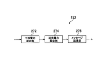
- FIG. 6 is a second functional block configuration diagram of the control unit in the radio base station according to the embodiment of the present invention.
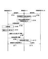
- FIG. 7 is a sequence diagram showing an operation of the radio communication system according to the embodiment of the present invention.
- FIG. 8 is a flowchart showing the operation of the connection destination radio base station according to the embodiment of the present invention.
- FIG. 9 is a flowchart showing the operation of the unconnected radio base station according to the embodiment of the present invention.
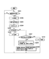
- FIG. 10 is a flowchart showing an operation of the radio terminal according to the embodiment of the present invention.
- FIG. 11 is a diagram illustrating an example of a modulation class table.
- FIG. 1 is an overall schematic configuration diagram of a radio communication system 10 according to an embodiment of the present invention.
- the radio communication system 10 includes a radio terminal 1A, a radio terminal 1B, and a radio terminal 1C, and a radio base station 2A, a radio base station 2B, and a radio base station 2C.
- the wireless communication system 10 has a configuration based on LTE, which is a standard formulated by 3GPP.
- a radio terminal 1A is located in a cell 3A provided by a radio base station 2A.
- the wireless terminal 1B is located in a cell 3B provided by the wireless base station 2B
- the wireless terminal 1C is located in a cell 3C provided by the wireless base station 2C.
- the wireless terminal 1A, the wireless terminal 1B, and the wireless terminal 1C each have communication quality (reception SNR, reception RSSI, reception FER, etc.) of reference signals and pilot signals transmitted from the radio base stations 2A to 2C at power-on and handover. And a location registration request is transmitted to the source radio base station such as a reference signal having the highest communication quality.
- the radio base station When receiving the location registration request from the radio terminal, the radio base station registers the location of the radio terminal and assigns a communication channel to the radio terminal. This enables communication between the wireless terminal and the wireless base station.
- the wireless terminal 1A is located in the cell 3A. For this reason, in the wireless terminal 1A, the communication quality such as the reference signal from the wireless base station 2A is usually the highest. In this case, the radio terminal 1A transmits a location registration request to the radio base station 2A. When receiving the location registration request from the wireless terminal 1A, the wireless base station 2A registers the location of the wireless terminal 1A and assigns a communication channel to the wireless terminal 1A.
- the wireless terminal 1A connects to the wireless base station 2A. Therefore, the radio base station 2A is a connection destination radio base station for the radio terminal 1A, and the radio base station 2B and the radio base station 2C are non-connection destination radio base stations for the radio terminal 1A.
- the wireless terminal 1B is located in the cell 3B. For this reason, in the radio terminal 1B, the communication quality such as the reference signal from the radio base station 2B is usually the highest. In this case, the wireless terminal 1B transmits a location registration request to the wireless base station 2B. When receiving the location registration request from the wireless terminal 1B, the wireless base station 2B registers the location of the wireless terminal 1B and assigns a communication channel to the wireless terminal 1B.
- the wireless terminal 1B connects to the wireless base station 2B. Therefore, the radio base station 2B is a connection destination radio base station for the radio terminal 1B, and the radio base station 2A and the radio base station 2C are non-connection destination radio base stations for the radio terminal 1B.
- the wireless terminal 1C is located in the cell 3C.
- the communication quality such as the reference signal from the wireless base station 2C is usually the highest.
- the radio terminal 1C transmits a location registration request to the radio base station 2C.
- the wireless base station 2C registers the location of the wireless terminal 1C and assigns a communication channel to the wireless terminal 1C.
- the wireless terminal 1C connects to the wireless base station 2C. Therefore, the radio base station 2C is a connection destination radio base station for the radio terminal 1C, and the radio base station 2A and the radio base station 2B are non-connection destination radio base stations for the radio terminal 1C.
- the radio terminal 1A transmits data to the radio base station 2A using the uplink communication channel.
- the radio base station 2A transmits data to the radio terminal 1A using the downlink communication channel.
- communication between the radio terminal 1B and the radio base station 2B and communication between the radio terminal 1C and the radio base station 2C are performed.
- FIG. 2 is a schematic configuration diagram of the radio terminal 1A.
- the wireless terminal 1A includes a control unit 102, a storage unit 103, an antenna 104, a wireless communication unit 106, a monitor 108, a microphone 110, a speaker 112, and an operation unit 114.
- the control unit 102 is configured by a CPU, for example, and controls various functions provided in the wireless terminal 1A.
- the storage unit 103 is configured by a memory, for example, and stores various information used for control and the like in the wireless terminal 1A.
- the wireless communication unit 106 includes an RF circuit, a baseband circuit, and the like, performs modulation and demodulation, encoding and decoding, and transmits and receives wireless signals via the antenna 104. Further, the wireless communication unit 106 periodically receives reference signals and the like transmitted from the wireless base stations 2A to 2C via the antenna 104.
- the monitor 108 displays an image received via the control unit 102 or displays an operation content (input telephone number, address, etc.).
- the microphone 110 collects sound and outputs sound data based on the collected sound to the control unit 102.
- the speaker 112 outputs sound based on the sound data acquired from the control unit 102.
- the operation unit 114 is configured by a numeric keypad, a function key, and the like, and is an interface used for inputting user operation details.
- FIG. 3 is a functional block configuration diagram of the control unit 102.
- the control unit 102 includes a power decrease request receiving unit 202, a power increase request / modulation method request receiving unit 204, a modulation class setting unit 208, a channel coding unit 210, and a mapping unit 212.
- the power reduction request receiving unit 202 receives a transmission power reduction request from the radio base station 2B and the radio base station 2C, which are non-connected radio base stations, to the radio terminal 1A.
- the transmission power reduction request is made by communicating on the uplink communication channel (communication channel from the radio terminal 1A to the radio base station 2A) between the radio terminal 1A and the radio base station 2A.
- the communication channel between the station 2B and the wireless terminal 1B) or the communication channel in the wireless base station 2C (the communication channel between the wireless base station 2C and the wireless terminal 1C) has generated interference power of a predetermined value or more.
- the radio base station 2B and the radio base station 2C transmit to the radio terminal 1A in order to reduce the transmission power of the uplink communication channel in the radio base station 2A and further reduce the interference power.
- the power reduction request receiving unit 202 outputs the received transmission power reduction request to the modulation class setting unit 208.
- the power increase request / modulation method request receiving unit 204 receives a transmission power increase request and a modulation method request from the wireless base station 2A which is a connection destination wireless base station.
- the transmission power increase request is for increasing the transmission power of the uplink communication channel in the radio base station 2A and improving the communication quality when the communication quality of the uplink communication channel in the radio base station 2A is less than a predetermined level.
- the radio base station 2A transmits to the radio terminal 1A.
- the modulation scheme request is transmitted from the radio base station 2A to the radio terminal 1A so that a predetermined modulation scheme is used in communication on the uplink communication channel in the radio base station 2A.
- the power increase request / modulation method request receiving unit 204 outputs the received transmission power increase request and modulation method request to the modulation class setting unit 208.
- the modulation class setting unit 208 sets a modulation class that combines the transmission power and modulation scheme of the uplink communication channel based on the input transmission power decrease request, transmission power increase request, and modulation scheme request (described later in FIG. 11). . Further, modulation class setting section 208 outputs the set uplink communication channel modulation class to mapping section 212.
- the channel coding unit 210 When the data to be transmitted using the uplink communication channel is input, the channel coding unit 210 adds CRC (Cyclic Redundancy Check) data for error correction to the data and performs channel coding processing such as encoding. Further, channel coding section 210 outputs the data after channel coding processing to mapping section 212.
- CRC Cyclic Redundancy Check
- the mapping unit 212 modulates the data from the channel coding unit 210 according to the modulation scheme indicated by the modulation class of the uplink communication channel from the modulation class setting unit 208. Further, the mapping unit 212 transmits a radio signal that is a modulated signal to the radio base station 2A using the uplink communication channel with the transmission power indicated by the modulation class of the uplink communication channel.
- FIG. 4 is a schematic configuration diagram of the radio base station 2A.
- the radio base station 2A includes a control unit 152, a storage unit 153, an I / F unit 154, a radio communication unit 156, and an antenna 158.
- the control unit 152 is configured by a CPU, for example, and controls various functions provided in the radio base station 2A.
- the storage unit 153 is configured by a memory, for example, and stores various information used for control and the like in the radio base station 2A.
- the I / F unit 154 is connected to an access gateway or the like existing in the network via a router or the like.
- the wireless communication unit 156 includes an RF circuit, a baseband circuit, and the like, performs modulation and demodulation, encoding and decoding, and transmits and receives wireless signals via the antenna 158. In addition, the wireless communication unit 156 transmits a reference signal and the like via the antenna 158.
- FIG. 5 is a functional block configuration diagram of the control unit 152 of the radio base station 2A when the radio base station 2A is a connection-destination radio base station for the radio terminal 1A.
- the control unit 152 of the radio base station 2B when the radio base station 2B is a connection destination radio base station for the radio terminal 1B and the radio base station 2C are the connection destination radio base stations for the radio terminal 1C. Since the control unit 152 of the radio base station 2B is the same as the control unit 152 of the radio base station 2A, the description thereof is omitted.
- control unit 152 includes a CQI measurement unit 252, a demapping unit 254, a decoding unit 256, a CRC check unit 258, a transmission power / modulation scheme setting unit 260, and a message transmission unit 262.
- the CQI measurement unit 252 When receiving a radio signal transmitted from the radio terminal 1A via the uplink communication channel, the CQI measurement unit 252 measures the CQI of the uplink communication channel. Further, the CQI measurement unit 252 outputs the received radio signal to the demapping unit 254 and outputs the measured CQI to the transmission power / modulation method setting unit 260. When the demapping unit 254 receives the radio signal from the CQI measurement unit 252, the demapping unit 254 demodulates the radio signal. Further, the demapping unit 254 outputs the data obtained by demodulation to the decoding unit 256.
- the decoding unit 256 decodes the data from the demapping unit 254, and outputs the decoded data to the CRC check unit 258.
- the CRC check unit 258 receives data from the demapping unit 254 and performs error detection based on CRC data included in the data. Further, CRC check section 258 outputs the result of error detection to transmission power / modulation scheme setting section 260.
- the transmission power / modulation method setting unit 260 receives the CQI from the CQI measurement unit 252 and the error detection result from the CRC check unit 258. Next, when the error detection result indicates that the radio signal is not normally received, the transmission power / modulation scheme setting unit 260 uses the CQI to perform transmission for communication on the uplink communication channel. Set power and modulation scheme.
- the transmission power to be set is a value larger than the transmission power used for the communication on the uplink communication channel immediately before. Further, transmission power / modulation scheme setting section 260 outputs the set transmission power value and modulation scheme information to message transmission section 262.
- the message transmission unit 262 includes a transmission power increase request including the value of the transmission power from the transmission power / modulation method setting unit 260, and a modulation method request including the modulation method information from the transmission power / modulation method setting unit 260. Is transmitted to the wireless terminal 1A using the downlink communication channel.
- FIG. 6 is a functional block configuration diagram of the control unit 152 of the radio base station 2A when the radio base station 2A is a non-connection destination radio base station for the radio terminal 1B and the radio terminal 1C.
- the control unit 152 of the radio base station 2B when the radio base station 2B is a non-connection destination radio base station for the radio terminal 1A or the radio terminal 1C, or the radio base station 2C is the radio terminal 1A or the radio terminal 1B.
- the control unit 152 of the radio base station 2C in the case of becoming a non-connection-destination radio base station is also the same as the control unit 152 of the radio base station 2A, and thus description thereof is omitted.
- control unit 152 includes an interference power measurement unit 272, a transmission power setting unit 274, and a message transmission unit 276.
- the interference power measurement unit 272 measures the interference power generated in the communication channel between the radio terminal 1A and the radio base station 2A by communication on the uplink communication channel between the radio terminal 1B and the radio base station 2B. Further, the interference power measurement unit 272 outputs the value of the interference power to the transmission power setting unit 274.
- the transmission power setting unit 274 determines the uplink communication channel between the radio terminal 1B and the radio base station 2B based on the interference power value. Sets the transmission power used for communication in.
- the set transmission power is a value smaller than the transmission power used for the communication on the uplink communication channel between the radio terminal 1B and the radio base station 2B immediately before. Further, the transmission power setting unit 274 outputs the set transmission power value to the message transmission unit 276.
- the message transmission unit 276 transmits a transmission power reduction request including the value of the transmission power from the transmission power setting unit 274 to the wireless terminal 1B and the wireless terminal 1C.
- interference power is generated in the communication channel between the wireless terminal 1A and the wireless base station 2A by communication on the uplink communication channel between the wireless terminal 1C (wireless terminal 1B) and the wireless base station 2C (wireless base station 2B). Even when the interference occurs, the interference power measurement unit 272, the transmission power setting unit 274, and the message transmission unit 276 perform the same processing as described above.
- Radio base station 2A is a connection destination radio base station and the radio base station 2B and the radio base station 2C are non-connection destination radio base stations will be described as an example for the radio terminal 1A.
- FIG. 7 is a sequence diagram showing an operation when the wireless terminal 1A connects to the wireless base station 2A in the wireless communication system 10.
- step S101 the radio base station 2A transmits a reference signal.
- the radio terminal 1A receives a reference signal from the radio base station 2A when the power is turned on or at the time of handover.
- step S102 the radio base stations 2B and 2C transmit reference signals.
- the radio terminal 1A receives reference signals from the radio base stations 2B and 2C at power-on or handover.
- the wireless terminal 1A measures the communication quality (for example, CQI) of each received reference signal.
- the radio terminal 1A determines the radio base station that is the source of the reference signal having the highest communication quality as the connection destination radio base station.
- the radio base station 2A is a connection-destination radio base station for the radio terminal 1A.
- step S105 the radio terminal 1A transmits a location registration request to the radio base station 2A that is a connection-destination radio base station.
- the radio base station 2A receives the location registration request from the radio terminal 1A.
- step S106 the radio base station 2A registers the location of the radio terminal 1A.
- the radio base station 2A allocates communication channels (uplink communication channel and downlink communication channel) to the radio terminal 1A. Further, in step S108, the radio base station 2A transmits communication channel allocation information including identification information of the allocated communication channel to the radio terminal 1A. The radio terminal 1A receives communication channel assignment information from the radio base station 2A.
- step S109 the radio base station 2A transmits information on the initial value of the transmission power (initial transmission power information) to the radio terminal 1A.
- the wireless terminal 1A receives the initial transmission power information from the wireless base station 2A.
- step S110 the radio terminal 1A sets the initial transmission power in the uplink communication channel based on the received initial transmission power information. Furthermore, in step S111, the radio terminal 1A transmits a radio signal to the radio base station 2A with the initial transmission power using the allocated uplink communication channel. The radio base station 2A receives a radio signal from the radio terminal 1A.
- the radio signal transmitted by the radio terminal 1A may be an interference signal of a communication channel in the radio base stations 2B and 2C.
- FIG. 8 is a flowchart showing an operation of the radio base station 2A that is a connection-destination radio base station for the radio terminal 1A.
- step S201 the control unit 152 of the radio base station 2A determines whether or not a radio signal from the radio terminal 1A has been received.
- step S202 the CQI measurement unit 252 in the control unit 152 measures the CQI of the uplink communication channel.
- step S203 the demapping unit 254 in the control unit 152 demodulates the radio signal. Further, the decoding unit 256 decodes data obtained by demodulation.
- step S204 the CRC check unit 258 performs error detection (CRC check) based on the CRC data included in the data obtained by decoding.
- CRC check error detection
- step S205 the transmission power / modulation method setting unit 260 in the control unit 152 determines whether or not the radio signal is normally received based on the error detection result in the CRC check unit 258. Specifically, transmission power / modulation scheme setting section 260 determines that the radio signal has not been normally received when error correction based on CRC data is impossible.
- step S206 the message transmission unit 262 in the control unit 152 sends an ACK, which is a response indicating that the radio signal from the radio terminal 1A has been normally received, to the radio terminal 1A. Send.
- step S207 the transmission power / modulation method setting unit 260 in the control unit 152 determines whether the number of retransmissions of the radio signal that has not been normally received has reached a predetermined number. Determine whether or not.
- step S210 the transmission power / modulation scheme setting unit 260 in the control unit 152 discards data corresponding to the radio signal whose number of retransmissions has reached the predetermined number.
- step S208 the transmission power / modulation scheme setting unit 260 in the control unit 152 determines whether or not the uplink communication channel is based on the CQI measured by the CQI measurement unit 252. Sets transmission power and modulation method used for communication.
- step S209 the message transmission unit 262 in the control unit 152 generates a transmission power increase request including the transmission power value set by the transmission power / modulation method setting unit 260, and also transmits the transmission power / modulation method setting unit 260.
- a modulation scheme request including information on the modulation scheme set by is generated.
- the message transmission unit 262 in the control unit 152 transmits the transmission power increase request and the modulation scheme request to the wireless terminal 1A by including them in the NACK that is a retransmission request of the wireless signal.
- FIG. 9 is a flowchart showing the operation of the radio base station 2B which is a non-connection destination radio base station for the radio terminal 1A. Note that the radio base station 2C, which is a non-connection destination radio base station for the radio terminal 1A, performs the same operation as the radio base station 2B.
- step S251 the control unit 152 of the radio base station 2B determines whether or not an interference signal from the radio terminal 1A has been received.
- the interference power measurement unit 272 in the control unit 152 measures the interference power.
- step S253 the transmission power setting unit 274 in the control unit 152 determines whether or not the value of the interference power is a predetermined value or more. When the interference power value is equal to or greater than the predetermined value, in step S254, the transmission power setting unit 274 in the control unit 152 performs uplink communication between the radio terminal 1A and the radio base station 2A based on the interference power value. Sets the transmission power used for communication on the channel.
- step S255 the message transmission unit 276 in the control unit 152 transmits a transmission power reduction request including the transmission power value set by the transmission power setting unit 274 to the wireless terminal 1A.
- FIG. 10 is a flowchart showing the operation of the wireless terminal 1A.
- step S301 the power increase request / modulation method request reception unit 204 in the control unit 102 determines whether or not a NACK has been received from the radio base station 2A that is a connection destination radio base station.
- the power reduction request receiving unit 202 in the control unit 102 further transmits from at least one of the radio base station 2B and the radio base station 2C that are non-connected radio base stations. It is determined whether a power reduction request is received.
- step S303 the modulation class setting unit 208 in the control unit 102 starts setting the transmission power and modulation scheme of the uplink communication channel.
- step S304 the modulation class setting unit 208 in the control unit 102, based on the modulation class table stored in the storage unit 103, the value of the transmission power requested by the radio base station 2A that is the connected radio base station, that is, Then, it is determined whether or not the transmission power value included in the transmission power increase request in the received NACK is the lowest value among the transmission power values corresponding to the modulation scheme requested by the radio base station 2A. .
- FIG. 11 is a diagram showing a modulation class table stored in the storage unit 103.
- each modulation class numbered in order from 1 is the transmission power value of the uplink communication channel and the modulation scheme in which the CQI is equal to or higher than a required level in the case of the transmission power value. Are combined.
- the transmission power value decreases as the corresponding modulation class number decreases, and increases as the corresponding modulation class number increases. Therefore, the transmission power A (1) corresponding to the modulation class number 1 is the smallest, and the transmission power A (N + M + L) corresponding to the modulation class number N + M + L is the largest.
- the modulation class table shown in FIG. 11 there are three types of modulation schemes, QPSK, 16QAM, and 64QAM, in order from the smaller corresponding modulation class number.
- QPSK, 16QAM, and 64QAM modulation schemes are used for the uplink communication channel and communication is performed with the same transmission power
- the CQI is QPSK, 16QAM, and 64QAM in order of goodness. That is, in the example of FIG. 11, the CQI is better for a modulation scheme with a smaller corresponding modulation class number.
- step S304 the modulation class setting unit 208 in the control unit 102 determines that the value of the transmission power requested by the radio base station 2A as the connection destination radio base station is A.
- a (N + 1), or A (N + M + 1) the transmission power value is the lowest value among the transmission power values corresponding to the modulation scheme requested by the radio base station 2A. Judge that there is.
- the modulation class setting unit 208 in the control unit 102 uses QPSK as the modulation method requested by the radio base station 2A that is the connection-destination radio base station, that is, the modulation method included in the modulation method request in the received NACK. It is determined whether or not.
- the modulation class setting unit 208 in the control unit 102 determines that the modulation class number 1 (modulation class 1), That is, a modulation class with a transmission power value of A (1) and a modulation scheme of QPSK is set.
- step S304 the value of the transmission power requested by the radio base station 2A that is the connection-destination radio base station is not the lowest value among the transmission power values corresponding to the modulation scheme requested by the radio base station 2A. If it is determined, or if it is determined in step S305 that the modulation scheme requested by the radio base station 2A that is the connection-destination radio base station is not QPSK, in step S307, the modulation class setting unit in the control unit 102 208 determines whether or not a transmission power reduction request has been received from a plurality of unconnected wireless base stations (in this case, the wireless base station 2B and the wireless base station 2C).
- a transmission power reduction request has been received from a plurality of unconnected wireless base stations (in this case, the wireless base station 2B and the wireless base station 2C).
- step S308 the modulation class setting unit 208 in the control unit 102 determines whether the transmission power values included in the transmission power reduction requests are different. Determine whether or not.
- step S309 the modulation class setting unit 208 in the control unit 102 selects the lowest value or the average value of the transmission power values.
- step S307 it is determined that a transmission power reduction request from a plurality of non-connection-destination radio base stations has not been received, that is, a transmission power reduction request from a single non-connection-destination radio base station has been received.
- step S310 the modulation class setting unit 208 in the control unit 102 selects a transmission power value included in a transmission power reduction request from a single non-connection destination radio base station. If it is determined in step S308 that the transmission power values included in the transmission power reduction requests are the same, the modulation class setting unit 208 in the control unit 102 sets the same transmission power value in step S310. select.
- step S311 the modulation class setting unit 208 in the control unit 102 selects the selected transmission power value (selected transmission power value),
- the modulation class of the uplink communication channel is set based on the modulation scheme requested by the radio base station 2A that is the connection-destination radio base station.
- the modulation class setting unit 208 in the control unit 102 refers to the modulation class table, extracts the modulation class having the selected transmission power value, and sets it as the modulation class of the uplink communication channel. At this time, if there is no modulation class having the selected transmission power value, the modulation class setting unit 208 in the control unit 102 is smaller than the selected transmission power value among the modulation classes and has a selected transmission power value. A modulation class combining the transmission power values closest to is set.
- the modulation class setting unit 208 in the control unit 102 determines whether or not the modulation method of the set modulation class matches the modulation method requested by the radio base station 2A that is the connection-destination radio base station. .
- the modulation class setting unit 208 in the control unit 102 sets the set modulation class. Do not change.
- the modulation class setting section 208 in the control unit 102 Two approaches can be taken.
- the modulation class setting unit 208 in the control unit 102 does not change the set modulation class.
- the control unit 102 when the CQI of the modulation scheme required by the radio base station 2A that is the connection-destination radio base station is better than the CQI of the modulation scheme that the set modulation class has, the control unit 102 The modulation class setting unit 208 changes the modulation class having the maximum transmission power value among the modulation classes having the modulation scheme required by the radio base station 2A that is the connection-destination radio base station.
- the modulation class setting section 208 in the control section 102 Does not change the set modulation class.
- the uplink communication channel When communication causes interference power of a predetermined value or more to occur in a communication channel in the radio base station 2B or the radio base station 2C that is a non-connected radio base station, the radio terminal 1A A transmission power reduction request for the uplink communication channel from the radio base station 2C is received.
- the wireless base station 2A which is the connection-destination wireless base station, cannot normally receive the wireless signal from the wireless terminal 1A
- the wireless terminal 1A uses the uplink communication channel from the wireless base station 2A. The transmission power increase request is received.
- the radio base station 2B and the radio base station 2C which are non-connection destination radio base stations
- the radio base station 2A which is a connection destination radio base station
- the wireless terminal 1A lowers the transmission power of the uplink communication channel in response to a transmission power reduction request from the wireless base station 2B or the wireless base station 2C that is a non-connected wireless base station. . Therefore, the interference power generated in the communication channel in the radio base station 2B and the radio base station 2C, which are non-connected radio base stations, is suppressed.
- the wireless terminal 1A refers to the modulation class table, and the CQI is reduced even when the transmission power decreased and the modulation scheme corresponding to the transmission power, that is, the transmission power of the uplink communication channel decreases.
- a modulation class having a modulation scheme that is a required level or higher is set.
- the interference power generated in the communication channel in the radio base station 2B and the radio base station 2C is suppressed, and the deterioration of the CQI of the uplink communication channel in the radio base station 2A that is the connection destination radio base station is suppressed.
- the radio base station 2A that is a connection-destination radio base station transmits a modulation scheme request to the radio terminal 1A
- the modulation included in the modulation scheme request When the CQI of the scheme deteriorates more than the CQI of the modulation scheme that the set modulation class has, the wireless terminal 1A does not change the set modulation class. Therefore, it is possible to appropriately suppress deterioration in communication quality of the uplink communication channel.
- the modulation class setting unit 208 in the control unit 102 of the wireless terminal 1A immediately sets a modulation class when receiving a NACK from the wireless base station 2A that is a connection destination wireless base station.
- the modulation class setting unit 208 in the control unit 102 of the wireless terminal 1A increases the transmission power of the uplink communication channel only when transmitting the retransmission target radio signal corresponding to NACK, and then disconnects.
- the transmission power of the uplink communication channel may be lowered in response to a transmission power reduction request from the radio base station 2B or the radio base station 2C, which is the destination radio base station.
- the radio communication system employing LTE has been described.
- the present invention is applied to any radio communication system that performs communication using an uplink communication channel between a radio terminal and a radio base station. Is possible.
- the wireless communication system, the wireless terminal, and the communication control method according to the present invention can appropriately perform both suppression of deterioration of communication quality and suppression of interference. Useful.
Landscapes
- Engineering & Computer Science (AREA)
- Computer Networks & Wireless Communication (AREA)
- Signal Processing (AREA)
- Quality & Reliability (AREA)
- Mobile Radio Communication Systems (AREA)
Abstract
Description
まず、本発明の実施形態に係る無線通信システムの構成について、(1.1)無線通信システムの全体概略構成、(1.2)無線端末の構成、(1.3)無線基地局の構成の順に説明する。
図1は、本発明の実施形態に係る無線通信システム10の全体概略構成図である。
次に、無線端末1A~1Cの構成について、(1.2.1)無線端末の概略構成、(1.2.2)無線端末の詳細構成の順に説明する。
図2は、無線端末1Aの概略構成図である。図2に示すように、無線端末1Aは、制御部102、記憶部103、アンテナ104、無線通信部106、モニタ108、マイク110、スピーカ112及び操作部114を含む。
次に、無線端末1Aの詳細構成、具体的には、制御部102の機能ブロック構成について説明する。図3は、制御部102の機能ブロック構成図である。図3に示すように、制御部102は、電力減少要求受信部202、電力増加要求・変調方式要求受信部204、変調クラス設定部208、チャネルコーディング部210及びマッピング部212を含む。
次に、無線基地局2A~1Cの構成について、(1.3.1)無線基地局の概略構成、(1.3.2)無線基地局の詳細構成の順に説明する。但し、無線基地局2B及び無線基地局2Cの概略構成は無線基地局2Aと同様であるため、無線基地局2B及び無線基地局2Cの概略構成についての説明は省略する。
図4は、無線基地局2Aの概略構成図である。図4に示すように、無線基地局2Aは、制御部152、記憶部153、I/F部154、無線通信部156及びアンテナ158を含む。
次に、無線基地局2A~1Cの詳細構成、具体的には、制御部152の機能ブロック構成について説明する。図5は、無線基地局2Aが無線端末1Aに対して接続先無線基地局となる場合の当該無線基地局2Aの制御部152の機能ブロック構成図である。なお、無線基地局2Bが無線端末1Bに対して接続先無線基地局となる場合の無線基地局2Bの制御部152と、無線基地局2Cが無線端末1Cに対して接続先無線基地局となる場合の無線基地局2Bの制御部152も、無線基地局2Aの制御部152と同様であるので、その説明は省略する。
デマッピング部254は、CQI測定部252からの無線信号を入力すると、当該無線信号を復調する。更に、デマッピング部254は、復調により得られたデータをデコード部256へ出力する。
まず、無線端末が無線基地局に接続する際の動作を説明する。以下においては、無線端末1Aに対して、無線基地局2Aが接続先無線基地局となり、無線基地局2B及び無線基地局2Cが非接続先無線基地局となる場合を例に説明する。
このように、本発明の実施形態に係る無線通信システム10によれば、無線端末1Aと接続先無線基地局である無線基地局2Aとの間で、上り通信チャネルでの通信が行われることにより、非接続先無線基地局である無線基地局2Bや無線基地局2Cにおける通信チャネルに所定値以上の干渉電力が生じる場合には、無線端末1Aは、無線基地局2Bや無線基地局2Cからの上り通信チャネルについての送信電力減少要求を受信する。また、接続先無線基地局である無線基地局2Aが無線端末1Aからの無線信号を正常に受信することができなくなった場合には、無線端末1Aは、無線基地局2Aからの上り通信チャネルについての送信電力増加要求を受信する。
上記のように、本発明は実施形態によって記載したが、この開示の一部をなす論述及び図面はこの発明を限定するものであると理解すべきではない。この開示から当業者には様々な代替実施形態、実施例及び運用技術が明らかとなる。
Claims (8)
- 無線端末と、
前記無線端末の接続先の無線基地局である接続先無線基地局と、
前記無線端末の接続先以外の無線基地局である非接続先無線基地局と
を含む無線通信システムであって、
前記接続先無線基地局は、
前記接続先無線基地局における上り通信チャネルの通信品質を測定する通信品質測定部と、
前記通信品質測定部により測定された前記通信品質が第1のレベル未満である場合に、前記上り通信チャネルの送信電力の増加を要求するための電力増加要求を前記無線端末へ送信する電力増加要求送信部と
を備え、
前記非接続先無線基地局は、
前記上り通信チャネルにおける通信により、前記非接続先無線基地局における通信チャネルに生じる干渉電力を測定する干渉電力測定部と、
前記干渉電力測定部により測定された前記干渉電力が第2のレベル以上である場合に、前記上り通信チャネルの送信電力の減少を要求するための電力減少要求を前記無線端末へ送信する電力減少要求送信部と
を備え、
前記無線端末は、
前記接続先無線基地局からの前記電力増加要求を受信する電力増加要求受信部と、
前記非接続先無線基地局からの前記電力減少要求を受信する電力減少要求受信部と、
前記電力増加要求受信部により前記電力増加要求が受信され、且つ、前記電力減少要求受信部により前記電力減少要求が受信された場合に、前記上り通信チャネルの送信電力及び変調方式を組み合わせた変調クラスについて、直前の送信電力よりも低い送信電力を設定するとともに、前記上り通信チャネルの通信品質が所要レベル以上となる変調方式を設定する変調クラス設定部と
を備える無線通信システム。 - 無線基地局との間で通信を行う無線端末であって、
接続先の無線基地局である接続先無線基地局から送信される、上り通信チャネルの送信電力の増加を要求するための電力増加要求を受信する電力増加要求受信部と、
接続先以外の無線基地局である非接続先無線基地局から送信される、前記上り通信チャネルの送信電力の減少を要求するための電力減少要求を受信する電力減少要求受信部と、
前記電力増加要求受信部により前記電力増加要求が受信され、且つ、前記電力減少要求受信部により前記電力減少要求が受信された場合に、前記上り通信チャネルの送信電力及び変調方式を組み合わせた変調クラスについて、直前の送信電力よりも低い送信電力を設定するとともに、前記上り通信チャネルの通信品質が所要レベル以上となる変調方式を設定する変調クラス設定部と
を備える無線端末。 - 前記電力減少要求は、送信電力値を含んでおり、
前記変調クラス設定部は、前記電力減少要求に含まれる前記送信電力値に対応する送信電力を設定する請求項2に記載の無線端末。 - 前記電力減少要求受信部は、複数の前記非接続先無線基地局のそれぞれから送信される複数の前記電力減少要求を受信し、
前記変調クラス設定部は、複数の前記電力減少要求に含まれる前記送信電力値の最小値及び平均値の何れかに対応する送信電力を設定する請求項3に記載の無線端末。 - 前記接続先無線基地局から送信される、前記上り通信チャネルの変調方式の設定を要求するための変調方式要求を受信する変調方式要求受信部を備え、
前記変調クラス設定部は、前記電力増加要求受信部により受信された前記変調方式要求に対応する変調方式を設定する請求項2乃至4の何れかに記載の無線端末。 - 前記変調クラス設定部は、前記変調方式要求に対応する変調方式を有する前記変調クラスでは、前記上り通信チャネルの通信品質が前記所要レベル未満となる場合に、前記変調方式要求に対応する変調方式の設定を中止する請求項5に記載の無線端末。
- 前記接続先無線基地局から送信される、再送要求を受信する再送要求受信部を備え、
前記変調クラス設定部は、前記再送要求受信部により前記再送要求が受信された場合に、前記再送要求の対象となる無線信号の送信時にのみ、直前の送信電力よりも高い送信電力を設定する請求項2に記載の無線端末。 - 無線基地局との間で通信を行う無線端末における通信制御方法であって、
前記無線端末が、接続先の無線基地局である接続先無線基地局から送信される、上り通信チャネルの送信電力の増加を要求するための電力増加要求を受信するステップと、
前記無線端末が、接続先以外の無線基地局である非接続先無線基地局から送信される、前記上り通信チャネルの送信電力の減少を要求するための電力減少要求を受信するステップと、
前記無線端末が、前記電力増加要求及び前記電力減少要求を受信した場合に、前記上り通信チャネルの送信電力及び変調方式を組み合わせた変調クラスについて、直前の送信電力よりも低い送信電力を設定するとともに、前記上り通信チャネルの通信品質が所要レベル以上となる変調方式を設定するステップと
を備える通信制御方法。
Priority Applications (1)
| Application Number | Priority Date | Filing Date | Title |
|---|---|---|---|
| US13/125,870 US8983519B2 (en) | 2008-10-28 | 2009-10-28 | Radio communication system, a radio terminal, and a communication control method for handling inconsistent power control requests |
Applications Claiming Priority (2)
| Application Number | Priority Date | Filing Date | Title |
|---|---|---|---|
| JP2008276942A JP5133200B2 (ja) | 2008-10-28 | 2008-10-28 | 無線通信システム、無線端末及び通信制御方法 |
| JP2008-276942 | 2008-10-28 |
Publications (1)
| Publication Number | Publication Date |
|---|---|
| WO2010050487A1 true WO2010050487A1 (ja) | 2010-05-06 |
Family
ID=42128847
Family Applications (1)
| Application Number | Title | Priority Date | Filing Date |
|---|---|---|---|
| PCT/JP2009/068453 Ceased WO2010050487A1 (ja) | 2008-10-28 | 2009-10-28 | 無線通信システム、無線端末及び通信制御方法 |
Country Status (4)
| Country | Link |
|---|---|
| US (1) | US8983519B2 (ja) |
| JP (1) | JP5133200B2 (ja) |
| KR (1) | KR20110090951A (ja) |
| WO (1) | WO2010050487A1 (ja) |
Families Citing this family (7)
| Publication number | Priority date | Publication date | Assignee | Title |
|---|---|---|---|---|
| US9113420B2 (en) | 2009-12-29 | 2015-08-18 | Telefonaktiebolaget L M Ericsson (Publ) | Radio system |
| CN102131279B (zh) * | 2010-11-26 | 2013-08-28 | 华为技术有限公司 | 一种发送功率调整方法和装置 |
| KR20120117575A (ko) * | 2011-04-15 | 2012-10-24 | 주식회사 케이티 | 무선 액세스 포인트 장치 및 신호 수신 감도 테스트 방법 |
| US8532691B2 (en) * | 2011-08-03 | 2013-09-10 | Intel Mobile Communications GmbH | Method and device for controlling a transmit power in a radio communications system |
| US10736051B2 (en) * | 2018-09-17 | 2020-08-04 | Charter Communications Operating, Llc | Variable power control in a wireless network |
| US11622355B2 (en) * | 2021-03-29 | 2023-04-04 | Cisco Technology, Inc. | Wireless fidelity uplink non-orthogonal multiple access |
| CA3261102A1 (en) * | 2022-07-15 | 2024-01-18 | Dexcom, Inc. | SYSTEMS AND METHODS FOR IMPROVED WIRELESS COMMUNICATIONS BETWEEN ANALYTE DETECTION SYSTEMS AND DISPLAY DEVICES |
Citations (2)
| Publication number | Priority date | Publication date | Assignee | Title |
|---|---|---|---|---|
| JP2003289280A (ja) * | 2002-03-28 | 2003-10-10 | Sony Corp | 無線通信システム、移動無線通信装置および方法、固定無線通信装置および方法、並びにプログラム |
| WO2008068803A1 (ja) * | 2006-11-30 | 2008-06-12 | Fujitsu Limited | 基地局装置及び移動端末 |
Family Cites Families (13)
| Publication number | Priority date | Publication date | Assignee | Title |
|---|---|---|---|---|
| US5265119A (en) * | 1989-11-07 | 1993-11-23 | Qualcomm Incorporated | Method and apparatus for controlling transmission power in a CDMA cellular mobile telephone system |
| JP2001144680A (ja) * | 1999-11-11 | 2001-05-25 | Mitsubishi Electric Corp | 通信方法および移動局 |
| WO2002017511A2 (en) | 2000-08-21 | 2002-02-28 | Koninklijke Philips Electronics N.V. | Method for the communication of information and apparatus employing the method |
| JP3543323B2 (ja) | 2001-02-14 | 2004-07-14 | 日本電気株式会社 | 基地局送信制御方法、セルラシステム及び基地局 |
| US6779147B2 (en) * | 2001-09-25 | 2004-08-17 | Qualcomm, Incorporated | Method and apparatus for efficient use of communication resources in a CDMA communication system |
| US7085290B2 (en) * | 2003-09-09 | 2006-08-01 | Harris Corporation | Mobile ad hoc network (MANET) providing connectivity enhancement features and related methods |
| US8452316B2 (en) * | 2004-06-18 | 2013-05-28 | Qualcomm Incorporated | Power control for a wireless communication system utilizing orthogonal multiplexing |
| EP2547162B1 (en) * | 2005-02-18 | 2015-10-28 | Fujitsu Limited | Interference reduction method in the base station |
| KR100964577B1 (ko) * | 2006-06-02 | 2010-06-21 | 삼성전자주식회사 | 통신 시스템에서 전력 제어 방법 및 시스템 |
| KR100765892B1 (ko) * | 2006-08-30 | 2007-10-10 | 주식회사 팬택 | 이동통신 시스템의 셀간 간섭을 제어하는 방법 |
| JP2008160380A (ja) * | 2006-12-22 | 2008-07-10 | Nec Corp | セル間干渉抑圧方法、無線基地局、ユーザ端末 |
| US8140105B2 (en) * | 2007-03-26 | 2012-03-20 | Telefonaktiebolaget L M Ericsson (Publ) | Method for controlling output power in a radio communications network |
| JP2009088915A (ja) * | 2007-09-28 | 2009-04-23 | Sony Corp | 無線送信装置、無線送信方法、無線通信システム及びプログラム |
-
2008
- 2008-10-28 JP JP2008276942A patent/JP5133200B2/ja not_active Expired - Fee Related
-
2009
- 2009-10-28 KR KR1020117011935A patent/KR20110090951A/ko not_active Ceased
- 2009-10-28 WO PCT/JP2009/068453 patent/WO2010050487A1/ja not_active Ceased
- 2009-10-28 US US13/125,870 patent/US8983519B2/en not_active Expired - Fee Related
Patent Citations (2)
| Publication number | Priority date | Publication date | Assignee | Title |
|---|---|---|---|---|
| JP2003289280A (ja) * | 2002-03-28 | 2003-10-10 | Sony Corp | 無線通信システム、移動無線通信装置および方法、固定無線通信装置および方法、並びにプログラム |
| WO2008068803A1 (ja) * | 2006-11-30 | 2008-06-12 | Fujitsu Limited | 基地局装置及び移動端末 |
Also Published As
| Publication number | Publication date |
|---|---|
| JP5133200B2 (ja) | 2013-01-30 |
| US20110223950A1 (en) | 2011-09-15 |
| JP2010109456A (ja) | 2010-05-13 |
| KR20110090951A (ko) | 2011-08-10 |
| US8983519B2 (en) | 2015-03-17 |
Similar Documents
| Publication | Publication Date | Title |
|---|---|---|
| US20250047426A1 (en) | User devices, wireless communication methods, and computer readable storage medium | |
| EP3726740A1 (en) | Electronic device, wireless communication method and computer-readable medium | |
| JP5029512B2 (ja) | 基地局装置、無線通信管理装置および無線通信システム | |
| US7826389B2 (en) | Communications method | |
| US10111236B2 (en) | Wireless communication apparatus and wireless communication method | |
| US20080107054A1 (en) | HARQ data reception in multiradio device | |
| JP5133200B2 (ja) | 無線通信システム、無線端末及び通信制御方法 | |
| JP4769834B2 (ja) | 無線通信システム、無線通信装置および無線通信方法 | |
| JPWO2002037715A1 (ja) | 移動局装置およびハンドオーバ方法 | |
| CN101088235A (zh) | 用于控制无线电接入的方法和设备 | |
| US20090143092A1 (en) | Power control | |
| US10958401B2 (en) | Electronic device and user equipment in wireless communication system and wireless communication method | |
| WO2009116120A1 (ja) | 無線端末装置および再送方法 | |
| US20260019215A1 (en) | Cqi enhancement for multi-link operation | |
| KR20100090337A (ko) | 대역 결합 시스템 및 그의 전송 대역 결정 방법 | |
| US8744461B2 (en) | Transmitting apparatus and receiving apparatus | |
| CN110662235B (zh) | 数据处理方法、主机单元、基站系统和存储介质 | |
| KR20070086773A (ko) | 통신 단말 및 이를 구비한 이동체 통신 시스템 | |
| JPWO2009031320A1 (ja) | 無線通信装置および送信方法 | |
| US20110306377A1 (en) | Radio communication system, radio base station, radio terminal, and communication control method | |
| US8625536B2 (en) | Communication system, communication control device, radio base station, and communication control method | |
| US8903320B1 (en) | Operating wireless communication systems in close proximity | |
| JP2010041285A (ja) | マルチバンド無線通信システムおよび端末装置 | |
| US11219053B2 (en) | Wireless communication method and device based on license-free band | |
| WO2023185659A1 (zh) | 用户设备、电子设备、无线通信方法和存储介质 |
Legal Events
| Date | Code | Title | Description |
|---|---|---|---|
| 121 | Ep: the epo has been informed by wipo that ep was designated in this application |
Ref document number: 09823597 Country of ref document: EP Kind code of ref document: A1 |
|
| WWE | Wipo information: entry into national phase |
Ref document number: 13125870 Country of ref document: US |
|
| NENP | Non-entry into the national phase |
Ref country code: DE |
|
| ENP | Entry into the national phase |
Ref document number: 20117011935 Country of ref document: KR Kind code of ref document: A |
|
| 122 | Ep: pct application non-entry in european phase |
Ref document number: 09823597 Country of ref document: EP Kind code of ref document: A1 |