WO2010047099A1 - スケーラブル動画像符号化方法、スケーラブル動画像符号化装置、スケーラブル動画像符号化プログラムおよびそのプログラムを記録したコンピュータ読み取り可能な記録媒体 - Google Patents
スケーラブル動画像符号化方法、スケーラブル動画像符号化装置、スケーラブル動画像符号化プログラムおよびそのプログラムを記録したコンピュータ読み取り可能な記録媒体 Download PDFInfo
- Publication number
- WO2010047099A1 WO2010047099A1 PCT/JP2009/005512 JP2009005512W WO2010047099A1 WO 2010047099 A1 WO2010047099 A1 WO 2010047099A1 JP 2009005512 W JP2009005512 W JP 2009005512W WO 2010047099 A1 WO2010047099 A1 WO 2010047099A1
- Authority
- WO
- WIPO (PCT)
- Prior art keywords
- prediction mode
- correspondence
- information
- encoding
- scalable
- Prior art date
Links
Images


Classifications
-
- H—ELECTRICITY
- H04—ELECTRIC COMMUNICATION TECHNIQUE
- H04N—PICTORIAL COMMUNICATION, e.g. TELEVISION
- H04N19/00—Methods or arrangements for coding, decoding, compressing or decompressing digital video signals
- H04N19/30—Methods or arrangements for coding, decoding, compressing or decompressing digital video signals using hierarchical techniques, e.g. scalability
-
- H—ELECTRICITY
- H04—ELECTRIC COMMUNICATION TECHNIQUE
- H04N—PICTORIAL COMMUNICATION, e.g. TELEVISION
- H04N19/00—Methods or arrangements for coding, decoding, compressing or decompressing digital video signals
- H04N19/10—Methods or arrangements for coding, decoding, compressing or decompressing digital video signals using adaptive coding
- H04N19/102—Methods or arrangements for coding, decoding, compressing or decompressing digital video signals using adaptive coding characterised by the element, parameter or selection affected or controlled by the adaptive coding
- H04N19/103—Selection of coding mode or of prediction mode
- H04N19/105—Selection of the reference unit for prediction within a chosen coding or prediction mode, e.g. adaptive choice of position and number of pixels used for prediction
-
- H—ELECTRICITY
- H04—ELECTRIC COMMUNICATION TECHNIQUE
- H04N—PICTORIAL COMMUNICATION, e.g. TELEVISION
- H04N19/00—Methods or arrangements for coding, decoding, compressing or decompressing digital video signals
- H04N19/10—Methods or arrangements for coding, decoding, compressing or decompressing digital video signals using adaptive coding
- H04N19/169—Methods or arrangements for coding, decoding, compressing or decompressing digital video signals using adaptive coding characterised by the coding unit, i.e. the structural portion or semantic portion of the video signal being the object or the subject of the adaptive coding
- H04N19/187—Methods or arrangements for coding, decoding, compressing or decompressing digital video signals using adaptive coding characterised by the coding unit, i.e. the structural portion or semantic portion of the video signal being the object or the subject of the adaptive coding the unit being a scalable video layer
-
- H—ELECTRICITY
- H04—ELECTRIC COMMUNICATION TECHNIQUE
- H04N—PICTORIAL COMMUNICATION, e.g. TELEVISION
- H04N19/00—Methods or arrangements for coding, decoding, compressing or decompressing digital video signals
- H04N19/10—Methods or arrangements for coding, decoding, compressing or decompressing digital video signals using adaptive coding
- H04N19/189—Methods or arrangements for coding, decoding, compressing or decompressing digital video signals using adaptive coding characterised by the adaptation method, adaptation tool or adaptation type used for the adaptive coding
- H04N19/196—Methods or arrangements for coding, decoding, compressing or decompressing digital video signals using adaptive coding characterised by the adaptation method, adaptation tool or adaptation type used for the adaptive coding being specially adapted for the computation of encoding parameters, e.g. by averaging previously computed encoding parameters
- H04N19/197—Methods or arrangements for coding, decoding, compressing or decompressing digital video signals using adaptive coding characterised by the adaptation method, adaptation tool or adaptation type used for the adaptive coding being specially adapted for the computation of encoding parameters, e.g. by averaging previously computed encoding parameters including determination of the initial value of an encoding parameter
-
- H—ELECTRICITY
- H04—ELECTRIC COMMUNICATION TECHNIQUE
- H04N—PICTORIAL COMMUNICATION, e.g. TELEVISION
- H04N19/00—Methods or arrangements for coding, decoding, compressing or decompressing digital video signals
- H04N19/50—Methods or arrangements for coding, decoding, compressing or decompressing digital video signals using predictive coding
- H04N19/503—Methods or arrangements for coding, decoding, compressing or decompressing digital video signals using predictive coding involving temporal prediction
- H04N19/51—Motion estimation or motion compensation
- H04N19/53—Multi-resolution motion estimation; Hierarchical motion estimation
-
- H—ELECTRICITY
- H04—ELECTRIC COMMUNICATION TECHNIQUE
- H04N—PICTORIAL COMMUNICATION, e.g. TELEVISION
- H04N19/00—Methods or arrangements for coding, decoding, compressing or decompressing digital video signals
- H04N19/50—Methods or arrangements for coding, decoding, compressing or decompressing digital video signals using predictive coding
- H04N19/503—Methods or arrangements for coding, decoding, compressing or decompressing digital video signals using predictive coding involving temporal prediction
- H04N19/51—Motion estimation or motion compensation
- H04N19/577—Motion compensation with bidirectional frame interpolation, i.e. using B-pictures
-
- H—ELECTRICITY
- H04—ELECTRIC COMMUNICATION TECHNIQUE
- H04N—PICTORIAL COMMUNICATION, e.g. TELEVISION
- H04N19/00—Methods or arrangements for coding, decoding, compressing or decompressing digital video signals
- H04N19/50—Methods or arrangements for coding, decoding, compressing or decompressing digital video signals using predictive coding
- H04N19/593—Methods or arrangements for coding, decoding, compressing or decompressing digital video signals using predictive coding involving spatial prediction techniques
Definitions
- the present invention relates to a scalable video encoding method and apparatus for encoding a video in a scalable manner, a scalable video encoding program used for realizing the scalable video encoding method, and a computer readable recording of the program And related recording media.
- the present invention relates to a scalable video encoding method and apparatus for realizing a reduction in encoding time, a scalable video encoding program used for realizing the scalable video encoding method, and a computer recording the program
- the present invention relates to a readable recording medium.
- JVT Joint Video Team
- AVC Advanced Video Coding Standard
- SVC Scalable Video Coding
- SVC adopts three prediction methods: Inter prediction, Intra prediction, and inter-layer prediction, and removes redundancy existing between time, space, and layers.
- the prediction modes that can be used in SVC are listed below.
- JSVM Joint Scalable Video Model, see Non-Patent Document 2, for example
- the coding cost consisting of the code amount and the coding distortion is calculated in each prediction mode.
- the prediction mode with the lowest coding cost among all prediction modes is determined as the optimum prediction mode.
- Patent Document 1 a vector obtained by extrapolating / interpolating the motion vector of the reference frame to the encoding target frame is generated, and the coordinates of each pixel of the moved macroblock are obtained thereby. The number of times to do is counted for each pixel.
- the prediction mode search candidates are narrowed down according to the score value calculated from the count number of each pixel in the encoding target macroblock.
- This narrowing method is described in H.C. H.264 / AVC is proposed for speeding up the prediction mode search.
- the present invention is also applicable to SVC, which is the same prediction mode search mechanism as H.264 / AVC.
- Patent Document 2 for example, nine screens of blocks that perform intra-frame coding using pixel values of adjacent coding blocks in order to perform intra-frame coding at high speed.
- An intra prediction error is obtained, and a prediction mode of the block is determined based on the intra prediction error.
- the prediction mode of the block is determined using the intra prediction mode of the adjacent coded block and the two prediction modes match, the prediction mode is selected as it is.
- the prediction mode with the lower coding cost is selected.
- this determination method requires an enormous amount of time for the prediction mode search. That is, in this determination method, a prediction mode (for example, an intra prediction mode in a still region) that is clearly not likely to be selected in consideration of the characteristics of an image in a macroblock is also searched for, which is wasteful.
- a prediction mode for example, an intra prediction mode in a still region
- narrowing down prediction mode search candidates in Patent Document 1 is a method for determining whether or not intra prediction is performed, and therefore, the effect of reducing the inter prediction mode search that requires a longer calculation time than the intra prediction mode search. There is no. In other words, there remains room for improvement in the Inter prediction mode search.
- the present invention has been made in view of such circumstances, and in scalable video coding that realizes scalability by a layer structure, narrowing down prediction mode search candidates for higher layers using the correlation of optimal prediction modes between layers.
- the purpose of this is to provide a new scalable video coding technology that increases the speed of the video.
- the scalable video coding apparatus provides (1) a prediction mode defined as usable in order to realize high speed prediction mode search in scalable video coding that achieves scalability by a layer structure. Based on the information of the optimal prediction mode selected by scalable coding performed without any restriction on use, the occurrence rate of the combination of the optimal prediction mode of the selected upper layer and lower layer in the spatially corresponding block is calculated.
- a correspondence table that describes the correspondence between the combination of the optimal prediction modes and the occurrence rate, and (2) spatially corresponding to the lower layer when encoding the upper layer block
- An acquisition unit that acquires information on the optimal prediction mode selected by encoding the block to be performed, and (3) acquisition of the acquisition unit Based on the information on the optimum prediction mode and the incidence information described in the correspondence table, an effective combination is extracted from the combinations of the optimum prediction modes described in the correspondence table, and the extracted combination has A determination unit that determines an optimal prediction mode of an upper layer as a prediction mode search candidate to be searched by encoding a block of the upper layer; and (4) a scalable code that restricts use of a prediction mode that is executed using a correspondence table. And a control unit that performs control to alternately repeat scalable encoding that does not limit the use of a prediction mode that is executed without using a correspondence table.
- the determination unit specifies the occurrence rate associated with the optimal prediction mode by referring to the correspondence table using the information of the optimal prediction mode acquired by the acquisition unit as a key. Next, the determination unit extracts a combination of optimum prediction modes having an occurrence rate that indicates a value larger than a predetermined threshold from the specified occurrence rate, or indicates the largest value from the specified occurrence rate. It is preferable to extract combinations of optimum prediction modes having an occurrence rate, or to extract combinations of optimum prediction modes having a predetermined number of occurrence rates selected in descending order from the specified occurrence rates. The determination unit determines the optimal prediction mode of the higher layer possessed by the combination of the extracted optimal prediction modes as a prediction mode search candidate to be searched by encoding the block of the higher layer.
- the scalable video encoding device of the present invention is preliminarily configured based on the occurrence rate value described in the correspondence table, and the optimal description described in the correspondence table. It is preferable to extract effective optimum prediction mode combinations by narrowing down prediction mode combinations and generate prediction mode correspondence information describing the extracted effective optimum prediction mode combinations.
- the scalable video encoding device of the present invention is defined as (1) usable in order to realize high speed prediction mode search in scalable video encoding that realizes scalability by a layer structure.
- the optimal prediction mode of the selected upper layer and lower layer in the spatially corresponding block A correspondence table generation unit for obtaining an occurrence rate of the combination and generating a correspondence table describing a correspondence relationship between the combination of the optimum prediction modes and the occurrence rate; and (2) an occurrence rate value described in the correspondence table.
- the effective prediction mode combinations that are effective by narrowing down the optimal prediction mode combinations described in the correspondence table
- a prediction mode correspondence information generating unit that generates prediction mode correspondence information describing the extracted effective optimum prediction mode combinations; and (3) when encoding a higher layer block, the lower layer spatial (4)
- an acquisition unit that acquires the information of the optimal prediction mode selected by encoding the block corresponding to
- a determination unit that determines a prediction mode search candidate to be searched by encoding a block of a higher layer
- scalable encoding that restricts use of a prediction mode executed using a correspondence table, and no correspondence table
- a control unit that performs control so as to alternately repeat scalable encoding that does not limit the use of the prediction mode executed in (1).
- the prediction mode correspondence information generation unit When adopting this configuration, the prediction mode correspondence information generation unit generates the prediction mode correspondence information by extracting the combination of the optimal prediction modes having an occurrence rate indicating a value larger than a predetermined threshold as valid.
- the prediction mode correspondence information is generated by extracting the optimal prediction mode combination having the highest occurrence rate from the combination of the optimal prediction modes having the same optimal prediction mode for the lower layer as effective.
- the prediction mode correspondence information may be generated by extracting a combination of a predetermined number of optimum prediction modes that are selected in the order of occurrence rates showing large values as effective.
- the scalable video encoding method of the present invention realized by the operation of each of the processing units described above can also be realized by a computer program, and the computer program is recorded on an appropriate computer-readable recording medium and provided. Or provided via a network, installed when implementing the present invention, and operating on a control unit such as a CPU, thereby realizing the present invention.
- the encoding mode is reduced by narrowing down prediction mode search candidates for higher layers using the correlation of optimal prediction modes between layers. can do.
- the narrowing is performed based on the correspondence relationship of the optimal prediction mode between layers in the encoded frame. It is possible to avoid the risk that the optimum prediction mode is omitted due to narrowing down. Therefore, it is possible to suppress a decrease in encoding performance that may occur by narrowing down prediction mode search candidates.
- FIG. 7 is a flowchart illustrating an example of a process for determining a prediction mode search candidate executed in the scalable video encoding process shown in FIG. 6.
- 7 is a flowchart illustrating another example of a process for determining a prediction mode search candidate executed in the scalable video encoding process shown in FIG. 6.
- 1 is a block diagram illustrating a scalable video encoding device according to an embodiment of the present invention.
- FIG. It is a block diagram which shows an example of the prediction mode search candidate determination part in the scalable video coding apparatus shown by FIG.
- It is a block diagram which shows the other example of the prediction mode search candidate determination part in the scalable video coding apparatus shown by FIG.
- both layer L and layer L-1 are encoded with the hierarchical B structure of IBBBP.
- Arrows in the figure indicate prediction reference destinations.
- the encoding target layer is L
- the encoding target frame is B2b
- the generation target frame of the prediction mode correspondence rate table is B2a.
- the frame of layer L-1 at the same time in B2b is B'2b
- the frame of layer L-1 at the same time in B2a is B'2a. It is assumed that encoding is performed in the order from the lowest time level, and in the same time level, the coding is performed in the order of frames in which the time is early. Further, it is assumed that layers are encoded in ascending order of level.
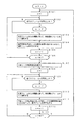
- step S101 when a moving image is scalable encoded, as shown in the flowchart of FIG. 2, whether or not all the frames are encoded in step S101 is set to 1 in the variable n. Judging. If it is determined that all frames have been encoded, the process is terminated.
- step S102 determines whether all the frames are not encoded according to the determination process in step S102. If it is determined that all the frames are not encoded according to the determination process in step S102, the process proceeds to step S103, and one unprocessed frame is selected according to the order from the top frame. In the subsequent step S104, the selected frame is predicted by performing prediction without limiting the use of the prediction mode defined as usable, that is, by performing prediction using all of the usable prediction modes. Is encoded.
- step S105 the value of the variable n is incremented by one.
- step S106 it is determined whether or not the value of the variable n has become larger than a predetermined threshold value N1 (N1 is an integer of 1 or more). If it is determined that the value of the variable n is not greater than the threshold value N1, the process returns to step S102 to encode the frame without limiting the use of the prediction mode defined as usable. continue.
- N1 is an integer of 1 or more
- step S106 when it is determined in step S106 that the value of the variable n has become larger than the threshold value N1, the process proceeds to step S107 to generate a prediction mode correspondence rate table.
- the prediction mode correspondence rate table is a table having a data structure as described later and describing the correlation (occurrence rate) of the optimum prediction mode between layers.
- step S108 1 is set in the variable n, and in the subsequent step S109, it is determined whether or not all frames have been encoded. If it is determined that all frames have been encoded, the process is terminated.
- step S109 when it is determined in step S109 that not all frames are encoded, the process proceeds to step S110.
- step S110 one unprocessed frame is selected according to the order from the first frame.
- step S111 the selected frame is encoded by performing prediction while narrowing down prediction mode search candidates using the prediction mode correspondence rate table.
- step S112 the value of the variable n is incremented by one.
- step S113 it is determined whether or not the value of the variable n has become larger than a predetermined threshold N2 (N2 is an integer of 1 or more). If it is determined that the value of the variable n is not greater than the threshold value N2, the process returns to step S109 to encode the frame while narrowing down prediction mode search candidates using the prediction mode correspondence rate table. continue.
- step S113 when it is determined in step S113 that the value of the variable n has become larger than the threshold value N2, it is determined that the prediction mode correspondence rate table needs to be updated, and the process returns to step S101. As a result, the processing of step S101 to step S113 is continued while updating the prediction mode correspondence rate table.
- the moving image when the moving image is scalable encoded, after N1 frames are encoded, the correlation (occurrence rate) of the optimal prediction mode between layers based on the encoding result.
- a prediction mode correspondence rate table that describes is generated.
- the process proceeds to encoding of N2 frames, and the encoding of N2 frames is repeated while narrowing down prediction mode search candidates using the generated prediction mode correspondence rate table. To do.
- step S104 the prediction mode correspondence rate table generation target frame B2a and the B'2a immediately below it have already been encoded, and the optimal prediction mode has already been selected.
- the frames B2a and B'2a are encoded, information on the selected optimum prediction mode is stored in the buffer.
- SMB spatially corresponding sub-macroblock
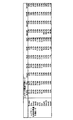
- a prediction mode correspondence rate table having a data structure as shown in FIG. 3 is generated between B2a and B'2a.
- the numerical values shown in FIG. 3 indicate the ratio (occurrence rate) that the optimal prediction mode j is selected in the MB of the frame B2a when the optimal prediction mode selected in each SMB (8 ⁇ 8 size) of the frame B′2a is i. ).
- the Skip mode is selected 32.3% in the MB of frame B2a spatially corresponding to the SMB in which P16 ⁇ 16 is selected. Is shown.
- the selection method of the optimal prediction mode in the frame B2a or B′2a may be the JSVM method described in Non-Patent Document 2 or the method of narrowing down prediction mode search candidates as described in Patent Document 1. good.
- the target frame of the prediction mode correspondence rate table is one encoded frame (B2a) at the same time level as the encoding target frame, but is not limited thereto. Encoded frames (for example, B1) at different time levels may be targeted.
- the correspondence rate may be calculated by accumulating the plurality of frames with a plurality of frames as targets (for example, B1 and B2a). That is, any frame that has been encoded in the encoding target layer and the layer immediately below it can be a prediction mode correspondence rate table generation target frame.
- the prediction mode search candidates are narrowed down in each MB of the encoding target frame B2b.
- a numerical value in the prediction mode correspondence rate table is regarded as a probability that can be an optimal prediction mode in the encoding target macroblock.
- the processing for narrowing down prediction mode search candidates will be described more specifically.
- the encoding target macroblock of the frame B2b is expressed as MBL
- the sub-macroblock of the frame B′2b of the layer L-1 that is spatially identical to the MBL is expressed as SMBL-1.
- the prediction mode search candidates of the macroblock MBL When narrowing down the prediction mode search candidates of the macroblock MBL, first, information on the optimal prediction mode of the sub macroblock SMBL-1 is read. Next, the prediction mode correspondence rate table is compared with the optimum prediction mode of SMBL-1, and the probability (correspondence rate) that can be the optimum prediction mode of each prediction mode in the encoding target macroblock MBL is investigated. Next, the prediction mode search candidates are narrowed down based on the probability that the optimum prediction mode can be obtained. Two examples of narrowing down are shown below.
- the narrowing down method 1 is a method of narrowing down prediction mode search candidates using a prediction mode search candidate narrowing threshold.
- a prediction mode search candidate narrowing down threshold value t% is provided, and a prediction mode less than this threshold value t% is excluded from the search candidates.
- the threshold value t is given from the outside.
- a method for determining a value a method for determining a value that suppresses deterioration in coding performance within an allowable range by a plurality of encoding processes may be considered.
- the probability (correspondence rate) that can be the optimal prediction mode of each prediction mode in MBL is read from the prediction mode correspondence rate table, and the prediction mode search candidate narrowing down threshold If the method of comparing is used, the comparison process becomes complicated.
- the correspondence rate of the prediction mode correspondence rate table is binarized in advance by thresholding the correspondence rate of the prediction mode correspondence rate table with the prediction mode search candidate narrowing threshold.
- FIG. 4 shows a prediction mode search candidate narrowing result when the prediction mode search candidate narrowing threshold is set to 5% in the prediction mode correspondence rate table shown in FIG.
- a circle indicates a prediction candidate
- a cross indicates a prediction mode excluded from the search candidate.
- the narrowing-down method 2 is a method of setting only a prediction mode with the highest prediction mode correspondence rate as a search candidate.
- the prediction mode that maximizes the prediction mode support rate is set as a search candidate. Normally, this is narrowed down to one prediction mode, but when there are a plurality of prediction mode search candidates giving the maximum value, they are all set as search candidates.
- the probability (correspondence rate) that can be the optimum prediction mode of each prediction mode in MBL is read from the prediction mode correspondence rate table, and the maximum value among them is read out. If the method of specifying the correspondence rate is used, the specifying process becomes complicated.
- the correspondence rate of the maximum value included in the correspondence rate of the prediction mode correspondence rate table is specified in advance, and the correspondence rate of the prediction mode correspondence rate table is binarized.
- FIG. 5 shows a narrowing result when the maximum prediction mode is set as a prediction mode search candidate in the prediction mode correspondence rate table shown in FIG.
- a circle indicates a prediction candidate
- a cross indicates a prediction mode excluded from the search candidate.
- 6 to 8 show flowcharts of scalable video encoding processing executed according to this embodiment.
- FIG. 6 is an overall flowchart of scalable video coding processing executed according to this embodiment.
- 7 and 8 are flowcharts showing an example of details of processing executed in step S201 of the flowchart of FIG. 6 and other examples.
- the encoding process of this embodiment is a process for the enhancement layer, and a non-scalable single layer encoding process is applied to the base layer.
- An example of the single layer encoding process is the encoding process of the base layer portion of the SVC reference encoder JSVM mentioned in Non-Patent Document 2.
- step S201 to step S206 executed in the flowchart of FIG. 6 will be described.
- step S201 the initial value of the prediction mode search candidate searched in the encoding target macroblock (MB) is read, and finally the prediction mode search candidate searched in the encoding target MB is determined and stored in the register. Details of this processing will be described later with reference to FIGS.
- step S202 the prediction mode search candidate information stored by the process of step S201 is read from the register, each prediction mode search candidate is searched, one optimal prediction mode used for encoding is determined, and Store information in a register.
- a method for determining the optimum prediction mode there is a method for optimizing a prediction mode that minimizes a coding cost expressed by a linear sum of a code amount and coding distortion performed in JSVM.
- step S203 information on the optimal prediction mode in the encoding target MB is read from the register, motion compensation is performed in the optimal prediction mode, a prediction residual signal is generated, and stored in the buffer.
- step S204 the prediction residual signal is read from the buffer, the prediction residual signal is encoded, and the encoded data is stored in the buffer.
- this process there is a series of processes of DCT, quantization, and variable length coding in the SVC reference encoder JSVM described in Non-Patent Document 2.
- step S205 it is determined whether or not all MBs have been encoded.
- the encoding process is terminated, the encoded data of each MB and other necessary header information are read from the buffer, and output as final encoded data.
- the process proceeds to step S206.
- step S206 the process proceeds to the next encoding target MB, and the processing in step S201 is performed.
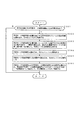
- step S201 Next, an example of specific processing executed in step S201 will be described using the flowchart of FIG. 7 including steps S301 to S306.
- step S301 information specifying whether the encoding target MB is a prediction mode search candidate narrowing target MB to which the present embodiment is applied is read.
- the process proceeds to step S302.
- the initial value of the prediction mode search candidate is output as the final prediction mode search candidate.
- step S302 the designation information of the encoded frame to be calculated in the prediction mode correspondence rate table is read from the outside, and the prediction mode information of the designated frame is stored in the register.
- step S303 the prediction mode information in the calculation target frame of the prediction mode correspondence rate table (information on the optimal prediction mode used in encoding) is read, and the correspondence rate between the encoding target layer and the optimal prediction mode of the layer immediately below it ( (Incidence rate) is calculated and stored in the register as a prediction mode correspondence rate table.
- a prediction mode correspondence rate table as shown in FIG. 3 is generated and stored in a register.
- step S304 the prediction mode correspondence rate table is read and stored in the buffer.
- step S305 the prediction mode search candidate narrowing threshold value is read and stored in a register.
- step S306 the prediction mode correspondence rate table is read from the buffer, and the prediction mode search candidate narrowing threshold is read from the register. Only prediction modes having a correspondence rate (occurrence rate) equal to or higher than the prediction mode search candidate narrowing threshold are set as prediction mode search candidates, and the information is stored in a register. In this setting / storage, only the prediction mode search candidate associated with the optimum prediction mode obtained by encoding the base layer is selected and set / stored.
- processing is performed so as to narrow down prediction mode search candidates in the form as shown in FIG. 4 based on the prediction mode correspondence rate table having the data structure as shown in FIG.
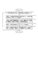
- step S201 Next, another example of specific processing executed in step S201 will be described using the flowchart of FIG. 8 including steps S401 to S405.
- step S401 information specifying whether or not the encoding target MB is a prediction mode search candidate narrowing target MB to which the present invention is applied is read.
- the process proceeds to step S402.
- the prediction mode search candidate initial value is output as the final prediction mode search candidate.
- step S402 the designation information of the encoded frame to be calculated in the prediction mode correspondence rate table is read from the outside, and the prediction mode information of the designated frame is stored in the register.
- step S403 the prediction mode information in the calculation target frame of the prediction mode correspondence rate table (information on the optimal prediction mode used in encoding) is read.
- the correspondence rate (occurrence rate) of the optimum prediction mode between the encoding target layer and the layer immediately below it is calculated and stored in the register as a prediction mode correspondence rate table. That is, a prediction mode correspondence rate table as shown in FIG. 3 is generated and stored in the register.
- step S404 the prediction mode correspondence rate table is read and stored in the buffer.
- step S405 the prediction mode correspondence rate table is read from the buffer, only the prediction mode having the maximum correspondence rate (occurrence rate) is set as a prediction mode search candidate, and the information is stored in the register.
- this setting / storage only the prediction mode search candidate associated with the optimum prediction mode obtained by encoding the base layer is selected and set / stored.
- processing is performed so as to narrow down prediction mode search candidates in the form as shown in FIG. 5 based on the prediction mode correspondence rate table having the data structure as shown in FIG.
- 9 to 11 illustrate the configuration of a scalable video encoding apparatus according to an embodiment of the present invention.
- FIG. 9 shows the overall configuration of the scalable video coding apparatus according to the present embodiment.
- FIGS. 10 and 11 show an example of the detailed configuration of the prediction mode search candidate determination unit 102 shown in FIG. 9 and other examples. Indicates.
- the scalable video encoding device of the present embodiment is a processing device for the enhancement layer, and a non-scalable single layer encoding process is applied to the base layer.
- An example of the single layer encoding process is the encoding process of the base layer portion of the SVC reference encoder JSVM mentioned in Non-Patent Document 2.
- the prediction mode search candidate initial value storage unit 101 reads the initial value of the prediction mode search candidate and outputs it to the register.
- the prediction mode search candidate determination unit 102 reads an initial value of the prediction mode search candidate and determines a prediction mode search candidate to be finally searched. Next, the prediction mode search candidate determination unit 102 outputs the finally determined prediction mode search candidate information to the register, and moves to the optimum prediction mode determination unit 103. The detailed configuration of this processing unit will be described later with reference to FIGS. 10 and 11.
- the optimal prediction mode determination unit 103 reads prediction mode search candidates from the register, and executes a search for each prediction mode search candidate. Next, the optimal prediction mode determination unit 103 determines one optimal prediction mode to be used for encoding, and outputs the information to the optimal prediction mode storage unit 104. As an example of a method for determining the optimum prediction mode, there is a method for optimizing a prediction mode that minimizes a coding cost expressed by a linear sum of a code amount and coding distortion performed in JSVM.
- the prediction residual signal generation unit 105 reads the optimal prediction mode in the encoding target MB from the optimal prediction mode storage unit 104, performs motion compensation in the optimal prediction mode, generates a prediction residual signal, and outputs it to the buffer To do.
- the prediction residual signal encoding unit 106 reads the prediction residual signal in the encoding target MB from the buffer, encodes the prediction residual signal, and outputs the encoded data to the buffer.
- An example of this processing is H.264.
- Application of a series of processes such as DCT, quantization, and variable length coding of the H.264 / AVC reference encoder JM and the SVC reference encoder JSVM described in Non-Patent Document 2 is conceivable.
- the all MB completion determination unit 107 performs a determination process as to whether or not encoding of all MBs has been completed. When the encoding of all MBs is completed, the encoding process is terminated and final encoded data is output. If encoding of all MBs is not completed, the process proceeds to the encoding target MB update unit 108.
- the encoding target MB update unit 108 moves to the next encoding target MB and performs the process of the prediction mode search candidate determination unit 102.
- the prediction mode search candidate narrowing-down target MB designation information storage unit 201 reads information that designates whether or not the prediction mode search candidate narrows down the prediction mode search candidate, and outputs it to a register.
- the prediction mode search candidate narrowing target MB determination unit 202 reads MB designation information for narrowing down prediction mode search candidates from the prediction mode search candidate narrowing target MB designation information storage unit 201, and the encoding target MB narrows down the MB. A process for determining whether or not there is present is performed. When the encoding target MB is an MB to be narrowed down, the process proceeds to the prediction mode correspondence rate table generation unit 206. When the encoding target MB is an MB for which no narrowing is performed, the initial value of the prediction mode search candidate is determined as the final prediction mode search candidate and output.
- the prediction mode correspondence rate calculation target frame designation information storage unit 203 reads the designation information of the encoded frame that is the calculation target of the prediction mode correspondence rate, and outputs it to the register.
- the target frame enhancement layer optimal prediction mode storage unit 204 performs optimal prediction in the encoding target layer for a frame for which the prediction mode correspondence rate indicated by the designation information read by the prediction mode correspondence rate calculation target frame designation information storage unit 203 is calculated. Read mode information and output to register.
- the optimal prediction mode storage unit 205 immediately below the target frame is a layer immediately below the encoding target layer for a frame for which the prediction mode correspondence rate indicated by the designation information read by the prediction mode correspondence rate calculation target frame designation information storage unit 203 is calculated. Reads the optimal prediction mode information in and outputs it to the register.
- the prediction mode correspondence rate table generation unit 206 reads the optimal prediction mode information in the encoding target layer of the calculation target frame of the prediction mode correspondence rate from the target frame enhancement layer optimal prediction mode storage unit 204. Furthermore, the prediction mode correspondence rate table generation unit 206 reads the optimum prediction mode information in the layer immediately below the encoding target layer of the prediction mode correspondence rate calculation target frame from the target frame direct layer optimum prediction mode storage unit 205, and performs the corresponding macro. The correspondence rate (occurrence rate) of the optimal prediction mode between the block and the sub-macroblock is calculated and output to the prediction mode correspondence rate table storage unit 207 as a prediction mode correspondence rate table.
- the prediction mode search candidate narrowing down threshold storage unit 208 reads the prediction mode search candidate narrowing down threshold and outputs it to the register.
- the prediction mode correspondence rate table threshold comparison unit 209 reads the prediction mode correspondence rate table from the prediction mode correspondence rate table storage unit 207 and also reads the prediction mode search candidate narrowing threshold value from the prediction mode search candidate narrowing threshold storage unit 208. Next, the prediction mode correspondence rate table threshold comparison unit 209 investigates the occurrence probability of the optimum prediction mode of the encoding target MB associated with the optimum prediction mode of the immediately lower SMB, and the occurrence probability is a prediction greater than or equal to the prediction mode search candidate narrowing threshold. Only the mode is set as the final prediction mode search candidate and output.
- the apparatus configuration shown in FIG. 10 performs processing to narrow down the prediction mode search candidates in the form shown in FIG. 4 based on the prediction mode correspondence rate table having the data structure shown in FIG. .
- the prediction mode search candidate narrowing-down target MB designation information storage unit 301 reads information that designates whether or not the prediction mode search candidate narrows down the prediction mode search candidate, and outputs the information to a register.
- the prediction mode search candidate narrowing-down target MB determination unit 302 reads MB designation information for narrowing down prediction mode search candidates from the prediction mode search candidate narrowing-down target MB designation information storage unit 301, and the encoding target MB narrows down. A process for determining whether or not there is present is performed. When the encoding target MB is an MB to be narrowed down, the process proceeds to the process of the prediction mode correspondence rate table generation unit 306. When the encoding target MB is an MB for which no narrowing is performed, the initial value of the prediction mode search candidate is determined as the final prediction mode search candidate and output.
- the prediction mode correspondence rate calculation target frame designation information storage unit 303 reads the designation information of the encoded frame that is the calculation target of the prediction mode correspondence rate, and outputs it to the register.
- the target frame enhancement layer optimal prediction mode storage unit 304 performs optimal prediction in the encoding target layer for a frame for which the prediction mode correspondence rate indicated by the designation information read by the prediction mode correspondence rate calculation target frame designation information storage unit 303 is calculated. Read mode information and output to register.
- the optimal prediction mode storage unit 305 immediately below the target frame is a layer immediately below the encoding target layer for the frame for which the prediction mode correspondence rate indicated by the designation information read by the prediction mode correspondence rate calculation target frame designation information storage unit 303 is calculated. Reads the optimal prediction mode information in and outputs it to the register.
- the prediction mode correspondence rate table generation unit 306 reads the optimal prediction mode information in the encoding target layer of the calculation target frame of the prediction mode correspondence rate from the target frame enhancement layer optimal prediction mode storage unit 304. Further, the prediction mode correspondence rate table generation unit 306 reads the optimal prediction mode information in the layer immediately below the encoding target layer of the prediction mode correspondence rate calculation target frame from the target frame immediate lower layer optimal prediction mode storage unit 305. Next, the prediction mode correspondence rate table generation unit 306 calculates the correspondence rate (occurrence rate) of the optimal prediction mode between the corresponding macroblock and sub-macroblock, and uses the prediction mode correspondence rate table as the prediction mode correspondence rate table. The data is output to the storage unit 307.
- the occurrence rate maximum prediction mode investigation unit 308 reads the prediction mode correspondence rate table from the prediction mode correspondence rate table storage unit 307, investigates the occurrence probability of the optimum prediction mode of the encoding target MB with respect to the optimum prediction mode of the direct SMB, The prediction mode with the highest probability is set as the final prediction mode search candidate and output.
- the apparatus configuration shown in FIG. 11 performs processing to narrow down prediction mode search candidates in the form shown in FIG. 5 based on the prediction mode correspondence rate table having the data structure shown in FIG. .
- As the images 704 ⁇ 576 size SVC test images “City” and “Soccer” and 1920 ⁇ 1024 size test images “Pedestrian” and “Station” were used.
- the video with the above resolution was input to the enhancement layer, and the video with the resolution of half the vertical and horizontal pixels was input to the base layer.
- the number of encoded sheets was 129, and QP (quantization parameter) was tested as 4, 27, 32, and 37, and the same value was used for both layers.
- the GOP (Group-of-Pictures) structure is a hierarchical B-picture structure of IBBBP, and I is inserted every 16 frames. As shown in FIG. 12, two frames belonging to the lowest time level were applied to the correspondence rate calculation frame and the high-speed mode selection frame, respectively.
- For the encoding time measurement a CPU of Xeon ⁇ 3.16 GHz was used.
- Table 1 below shows the experimental results of the code amount increase rate and the encoding time reduction rate.
- the code amount increase rate is obtained by generating an approximate curve between four points of the code amount and PSNR (Peak Signal to Noise Ratio) in each QP by Piecewise Cubic Hermite Polynominal Interpolation, and the common interval of the two data to be compared The average difference value of the amount of codes in was determined as the rate of increase.
- the encoding time reduction rate is an average value of the encoding time reduction rates in each QP.
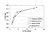
- FIG. 13 illustrates encoding characteristics in encoding “Pedestrian IV” and “Station” images
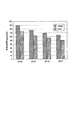
- FIG. 14 illustrates changes in encoding time in encoding “Pedestrian IV”.
- the present invention achieves a coding time reduction rate of around 20% while suppressing the code amount increase rate to less than 1% regardless of the resolution and video.
- the present invention is not limited to the embodiment described above.
- the example in which the present invention is applied to the hierarchical layer configuration of the base layer and the enhancement layer has been described.
- the application of the present invention is not limited to such a hierarchical layer configuration.
- the present invention can be applied to scalable video coding that realizes scalability by a layer structure, and the coding time can be reduced by applying the present invention.
- Prediction mode search candidate initial value storage unit 102 prediction mode search candidate determination unit 103 optimal prediction mode determination unit 104 optimal prediction mode storage unit 105 prediction residual signal generation unit 106 prediction residual signal encoding unit 107 all MB completion determination unit 108 Encoding target MB update unit 201 Prediction mode search candidate narrowing target MB designation information storage unit 202 Prediction mode search candidate narrowing target MB determination unit 203 Prediction mode correspondence rate calculation target frame designation information storage unit 204 Target frame enhancement layer optimum prediction mode storage unit 205 Predictive layer correspondence prediction table storage unit 206 Prediction mode correspondence rate table generation unit 207 Prediction mode correspondence rate table storage unit 208 Prediction mode search candidate narrowing threshold storage unit 209 Prediction mode correspondence rate table threshold comparison unit 301 Prediction mode search candidate narrowing down Target MB finger Information storage unit 302 Prediction mode search candidate narrowing down target MB determination unit 303 Prediction mode correspondence rate calculation target frame designation information storage unit 304 Target frame extended layer optimum prediction mode storage unit 305 Target frame direct layer optimum prediction mode storage unit 306 Prediction mode correspondence rate Table generation unit
Landscapes
- Engineering & Computer Science (AREA)
- Multimedia (AREA)
- Signal Processing (AREA)
- Computing Systems (AREA)
- Theoretical Computer Science (AREA)
- Compression Or Coding Systems Of Tv Signals (AREA)
- Compression, Expansion, Code Conversion, And Decoders (AREA)
Abstract
Description
本願は、2008年10月22日に、日本に出願された特願2008-271513号に基づき優先権を主張し、その内容をここに援用する。
・Skip モード(Skip )
・Direct モード(Direct )
・16×16ブロックサイズ動き予測モード(P16×16)
・16×8ブロックサイズ動き予測モード(P16×8)
・8×16ブロックサイズ動き予測モード(P8×16)
・8×8ブロックサイズ動き予測モード(P8×8)
〔Intra予測〕
・16×16ブロックサイズIntra予測モード(I16×16)
・8×8ブロックサイズIntra予測モード(I8×8)
・4×4ブロックサイズIntra予測モード(I4×4)
〔レイヤ間予測〕
・BLSkip モード(BLSkip )
・IntraBLモード(IntraBL)
P8×8を行う場合の各8×8ブロックは、さらに8×4、4×4、4×4のブロックサイズに分割可能である。SVCでは、マクロブロックごとに、これらの予測モード探索候補の中から1つを最適予測モードとして選択する。
本発明の一実施形態では、レイヤ構造によってスケーラビリティを実現するスケーラブル動画像符号化において、
(i)予測モード対応率表(レイヤ間の最適予測モードの相関性について記述する表)の生成
(ii)予測モード対応率表を使った予測モード探索候補の絞り込み
という2つの処理によって予測モード探索の高速化を実現する。
次に、ステップS107で実行する予測モード対応率表の生成処理について説明する。
次に、ステップS111における予測モード対応率表を使った予測モード探索候補の絞り込み処理について説明する。
絞り込み手法1は、予測モード探索候補絞り込み閾値を用いて予測モード探索候補を絞り込む手法である。
絞り込み手法2は、予測モード対応率が最大となる予測モードのみを探索候補と設定する手法である。
102 予測モード探索候補決定部
103 最適予測モード決定部
104 最適予測モード記憶部
105 予測残差信号生成部
106 予測残差信号符号化部
107 全MB完了判定部
108 符号化対象MB更新部
201 予測モード探索候補絞り込み対象MB指定情報記憶部
202 予測モード探索候補絞り込み対象MB判定部
203 予測モード対応率計算対象フレーム指定情報記憶部
204 対象フレーム拡張レイヤ最適予測モード記憶部
205 対象フレーム直下レイヤ最適予測モード記憶部
206 予測モード対応率表生成部
207 予測モード対応率表記憶部
208 予測モード探索候補絞り込み閾値記憶部
209 予測モード対応率表閾値比較部
301 予測モード探索候補絞り込み対象MB指定情報記憶部
302 予測モード探索候補絞り込み対象MB判定部
303 予測モード対応率計算対象フレーム指定情報記憶部
304 対象フレーム拡張レイヤ最適予測モード記憶部
305 対象フレーム直下レイヤ最適予測モード記憶部
306 予測モード対応率表生成部
307 予測モード対応率表記憶部
308 発生率最大予測モード調査部
Claims (10)
- 動画像をスケーラブルに符号化するスケーラブル動画像符号化方法であって、
使用可能として定義された予測モードの使用に制限を設けることなく行ったスケーラブル符号化において選択された最適予測モードの情報に基づいて、上位レイヤと下位レイヤとの空間的に対応するブロックについて選択すべき最適予測モードの組み合わせの発生率を求めて、前記選択された最適予測モードと前記選択すべき最適予測モードとの組み合わせと前記発生率との対応関係について記述する対応表を生成する過程と、
前記上位レイヤのブロックを符号化する場合に、前記下位レイヤの前記空間的に対応するブロックの符号化における前記選択された最適予測モードの情報を取得する過程と、
前記取得する過程において取得した前記選択された最適予測モードの情報と前記対応表に記述された前記発生率の情報とに基づいて、前記対応表に記述された前記組み合わせの中から有効な組み合わせを抽出して、抽出された前記有効な組み合わせの持つ前記上位レイヤの最適予測モードを、前記上位レイヤのブロックの符号化において探索すべき予測モード探索候補として決定する過程と、
を備えるスケーラブル動画像符号化方法。 - 動画像をスケーラブルに符号化するスケーラブル動画像符号化方法であって、
使用可能として定義された予測モードの使用に制限を設けることなく行ったスケーラブル符号化において選択された最適予測モードの情報に基づいて、上位レイヤと下位レイヤとの空間的に対応するブロックについて選択すべき最適予測モードの組み合わせの発生率を求めて、前記選択された最適予測モードと前記選択すべき最適予測モードとの組み合わせと前記発生率との対応関係について記述する対応表を生成する過程と、
前記発生率の値に基づいて、前記対応表に記述された前記選択された最適予測モードと前記選択すべき最適予測モードとの組み合わせを絞り込むことで有効な最適予測モードの組み合わせを抽出して、抽出された前記有効な最適予測モードの組み合わせについて記述する予測モード対応情報を生成する過程と、
前記上位レイヤのブロックを符号化する場合に、前記下位レイヤの前記空間的に対応するブロックの符号化における前記選択された最適予測モードの情報を取得する過程と、
前記取得する過程において取得した前記選択された最適予測モードの情報をキーにして前記予測モード対応情報を参照することによって、前記上位レイヤのブロックの符号化において探索すべき予測モード探索候補を決定する過程と、
を備えるスケーラブル動画像符号化方法。 - 請求項2に記載のスケーラブル動画像符号化方法において、
前記予測モード対応情報を生成する過程では、所定の閾値よりも大きな値を示す発生率を持つ前記組み合わせを有効なものとして抽出するスケーラブル動画像符号化方法。 - 請求項2に記載のスケーラブル動画像符号化方法において、
前記予測モード対応情報を生成する過程では、前記下位レイヤについて同一の最適予測モードを持つ最適予測モードの組み合わせの中から、最も大きな値を示す発生率を持つ前記組み合わせを有効なものとして抽出するか、あるいは、大きな値を示す発生率の順に選択される所定の個数の最適予測モードの組み合わせを有効なものとして抽出するスケーラブル動画像符号化方法。 - 請求項1ないし4のいずれか1項に記載のスケーラブル動画像符号化方法において、
前記対応表を用いて実行される予測モードの使用に制限を設けるスケーラブル符号化と、前記対応表を用いないで実行される予測モードの使用に制限を設けないスケーラブル符号化とを交互に繰り返すように制御する過程を備えるスケーラブル動画像符号化方法。 - 動画像をスケーラブルに符号化するスケーラブル動画像符号化装置であって、
使用可能として定義された予測モードの使用に制限を設けることなく行ったスケーラブル符号化において選択された最適予測モードの情報に基づいて、上位レイヤと下位レイヤとの空間的に対応するブロックについて選択すべき最適予測モードの組み合わせの発生率を求めて、前記選択された最適予測モードと前記選択すべき最適予測モードとの組み合わせと前記発生率との対応関係について記述する対応表を生成する生成部と、
前記上位レイヤのブロックを符号化する場合に、前記下位レイヤの前記空間的に対応するブロックの符号化における前記選択された最適予測モードの情報を取得する取得部と、
前記取得部において取得した前記選択された最適予測モードの情報と前記対応表に記述された前記発生率の情報とに基づいて、前記対応表に記述された前記組み合わせの中から有効な組み合わせを抽出して、抽出された前記有効な組み合わせの持つ前記上位レイヤの最適予測モードを、前記上位レイヤのブロックの符号化において探索すべき予測モード探索候補として決定する決定部と、
を備えるスケーラブル動画像符号化装置。 - 動画像をスケーラブルに符号化するスケーラブル動画像符号化装置であって、
使用可能として定義された予測モードの使用に制限を設けることなく行ったスケーラブル符号化において選択された最適予測モードの情報に基づいて、上位レイヤと下位レイヤとの空間的に対応するブロックについて選択すべき最適予測モードの組み合わせの発生率を求めて、前記選択された最適予測モードと前記選択すべき最適予測モードとの組み合わせと前記発生率との対応関係について記述する対応表を生成する対応表生成部と、
前記発生率の値に基づいて、前記対応表に記述された前記選択された最適予測モードと前記選択すべき最適予測モードとの組み合わせを絞り込むことによって有効な最適予測モードの組み合わせを抽出して、抽出された前記有効な最適予測モードの組み合わせについて記述する予測モード対応情報を生成する予測モード対応情報生成部と、
前記上位レイヤのブロックを符号化する場合に、前記下位レイヤの前記空間的に対応するブロックの符号化における前記選択された最適予測モードの情報を取得する取得部と、
前記取得部において取得され前記選択された最適予測モードの情報をキーにして前記予測モード対応情報を参照することによって、前記上位レイヤのブロックの符号化において探索すべき予測モード探索候補を決定する決定部と、
を備えるスケーラブル動画像符号化装置。 - 請求項6または7に記載のスケーラブル動画像符号化装置において、
前記対応表を用いて実行される予測モードの使用に制限を設けるスケーラブル符号化と、前記対応表を用いないで実行される予測モードの使用に制限を設けないスケーラブル符号化とを交互に繰り返すように制御する制御部を備えるスケーラブル動画像符号化装置。 - 請求項1ないし5のいずれか1項に記載のスケーラブル動画像符号化方法をコンピュータに実行させるためのスケーラブル動画像符号化プログラム。
- 請求項1ないし5のいずれか1項に記載のスケーラブル動画像符号化方法をコンピュータに実行させるためのスケーラブル動画像符号化プログラムを記録したコンピュータ読み取り可能な記録媒体。
Priority Applications (8)
| Application Number | Priority Date | Filing Date | Title |
|---|---|---|---|
| US13/123,690 US8509302B2 (en) | 2008-10-22 | 2009-10-21 | Scalable video encoding method, scalable video encoding apparatus, scalable video encoding program, and computer readable recording medium storing the program |
| BRPI0920213-7A BRPI0920213A2 (pt) | 2008-10-22 | 2009-10-21 | método de codificação de vídeo escalável, aparelho de codificação de vídeo escalável, programa de codificação de vídeo escalável, e meio de gravação legível por computador armazenando o programa |
| JP2010534689A JP5225388B2 (ja) | 2008-10-22 | 2009-10-21 | スケーラブル動画像符号化方法、スケーラブル動画像符号化装置、スケーラブル動画像符号化プログラムおよびそのプログラムを記録したコンピュータ読み取り可能な記録媒体 |
| EP09821799A EP2339853A4 (en) | 2008-10-22 | 2009-10-21 | EXTENSIBLE MOBILE IMAGE ENCODING METHOD, EXTENSIBLE MOBILE IMAGE ENCODING APPARATUS, EXTENSIBLE MOBILE IMAGE ENCODING PROGRAM, AND COMPUTER-READABLE RECORDING MEDIUM ON WHICH THIS PROGRAM IS RECORDED |
| RU2011114296/07A RU2488235C2 (ru) | 2008-10-22 | 2009-10-21 | Способ масштабируемого кодирования видео, устройство масштабируемого кодирования видео, программа масштабируемого кодирования видео и машиночитаемый носитель записи, сохраняющий программу |
| CA 2740467 CA2740467C (en) | 2008-10-22 | 2009-10-21 | Scalable video encoding method and scalable video encoding apparatus |
| CN2009801406274A CN102187677B (zh) | 2008-10-22 | 2009-10-21 | 可分级视频编码方法以及可分级视频编码装置 |
| KR1020117008317A KR101260369B1 (ko) | 2008-10-22 | 2009-10-21 | 스케일러블 동화상 부호화 방법, 스케일러블 동화상 부호화 장치, 스케일러블 동화상 부호화 프로그램 및 그 프로그램을 기록한 컴퓨터 판독 가능한 기록 매체 |
Applications Claiming Priority (2)
| Application Number | Priority Date | Filing Date | Title |
|---|---|---|---|
| JP2008-271513 | 2008-10-22 | ||
| JP2008271513 | 2008-10-22 |
Publications (1)
| Publication Number | Publication Date |
|---|---|
| WO2010047099A1 true WO2010047099A1 (ja) | 2010-04-29 |
Family
ID=42119152
Family Applications (1)
| Application Number | Title | Priority Date | Filing Date |
|---|---|---|---|
| PCT/JP2009/005512 WO2010047099A1 (ja) | 2008-10-22 | 2009-10-21 | スケーラブル動画像符号化方法、スケーラブル動画像符号化装置、スケーラブル動画像符号化プログラムおよびそのプログラムを記録したコンピュータ読み取り可能な記録媒体 |
Country Status (10)
| Country | Link |
|---|---|
| US (1) | US8509302B2 (ja) |
| EP (1) | EP2339853A4 (ja) |
| JP (1) | JP5225388B2 (ja) |
| KR (1) | KR101260369B1 (ja) |
| CN (1) | CN102187677B (ja) |
| BR (1) | BRPI0920213A2 (ja) |
| CA (1) | CA2740467C (ja) |
| RU (1) | RU2488235C2 (ja) |
| TW (1) | TWI401967B (ja) |
| WO (1) | WO2010047099A1 (ja) |
Cited By (3)
| Publication number | Priority date | Publication date | Assignee | Title |
|---|---|---|---|---|
| JP2011029962A (ja) * | 2009-07-27 | 2011-02-10 | Nippon Telegr & Teleph Corp <Ntt> | スケーラブル動画像符号化方法、スケーラブル動画像符号化装置およびスケーラブル動画像符号化プログラム |
| CN102355579A (zh) * | 2011-02-24 | 2012-02-15 | 中兴通讯股份有限公司 | 一种预测模式的编码或解码方法及装置 |
| WO2016140090A1 (ja) * | 2015-03-04 | 2016-09-09 | ソニー株式会社 | 画像符号化装置および方法 |
Families Citing this family (7)
| Publication number | Priority date | Publication date | Assignee | Title |
|---|---|---|---|---|
| TWI463876B (zh) * | 2011-05-17 | 2014-12-01 | Alpha Imaging Technology Corp | 影像壓縮方法 |
| US9654785B2 (en) | 2011-06-09 | 2017-05-16 | Qualcomm Incorporated | Enhanced intra-prediction mode signaling for video coding using neighboring mode |
| CN103237212B (zh) * | 2013-04-08 | 2016-04-13 | 浙江大学 | 一种生成增强层块单元编码信息参考队列的方法及装置 |
| US20150189269A1 (en) * | 2013-12-30 | 2015-07-02 | Google Inc. | Recursive block partitioning |
| WO2019117645A1 (ko) * | 2017-12-14 | 2019-06-20 | 한국전자통신연구원 | 예측 네트워크를 사용하는 영상의 부호화 및 복호화를 위한 방법 및 장치 |
| US11166014B2 (en) | 2017-12-14 | 2021-11-02 | Electronics And Telecommunications Research Institute | Image encoding and decoding method and device using prediction network |
| CN114143536B (zh) * | 2021-12-07 | 2022-09-02 | 重庆邮电大学 | 一种shvc空间可伸缩帧的视频编码方法 |
Citations (4)
| Publication number | Priority date | Publication date | Assignee | Title |
|---|---|---|---|---|
| JPH09322163A (ja) * | 1996-03-22 | 1997-12-12 | Sony Corp | 画像信号の符号化方法、伝送方法及び復号方法、符号化装置、伝送装置及び復号装置並びに記録媒体 |
| JP2005184241A (ja) | 2003-12-17 | 2005-07-07 | Kddi Corp | 動画像フレーム内モード判定方式 |
| JP2006033451A (ja) | 2004-07-16 | 2006-02-02 | Nippon Telegr & Teleph Corp <Ntt> | 符号化予測モード決定装置,符号化予測モード決定方法,符号化予測モード決定プログラムおよびその記録媒体 |
| JP2008271513A (ja) | 2007-03-28 | 2008-11-06 | Kyocera Corp | 携帯通信端末およびその制御方法 |
Family Cites Families (10)
| Publication number | Priority date | Publication date | Assignee | Title |
|---|---|---|---|---|
| US5768537A (en) | 1996-02-22 | 1998-06-16 | International Business Machines Corporation | Scalable MPEG2 compliant video encoder |
| US6031575A (en) | 1996-03-22 | 2000-02-29 | Sony Corporation | Method and apparatus for encoding an image signal, method and apparatus for decoding an image signal, and recording medium |
| KR100679025B1 (ko) * | 2004-11-12 | 2007-02-05 | 삼성전자주식회사 | 다 계층 기반의 인트라 예측 방법, 및 그 방법을 이용한비디오 코딩 방법 및 장치 |
| US20060153295A1 (en) * | 2005-01-12 | 2006-07-13 | Nokia Corporation | Method and system for inter-layer prediction mode coding in scalable video coding |
| WO2008060262A1 (en) | 2005-09-07 | 2008-05-22 | Vidyo, Inc. | System and method for scalable and low-delay videoconferencing using scalable video coding |
| KR100763196B1 (ko) * | 2005-10-19 | 2007-10-04 | 삼성전자주식회사 | 어떤 계층의 플래그를 계층간의 연관성을 이용하여부호화하는 방법, 상기 부호화된 플래그를 복호화하는방법, 및 장치 |
| WO2007063808A1 (ja) * | 2005-11-30 | 2007-06-07 | Kabushiki Kaisha Toshiba | 画像符号化/画像復号化方法及び画像符号化/画像復号化装置 |
| JP2009522972A (ja) * | 2006-01-09 | 2009-06-11 | ノキア コーポレイション | スケーラブルなビデオ符号化におけるエラー耐性を有するモード決定 |
| CN100584026C (zh) | 2006-03-27 | 2010-01-20 | 华为技术有限公司 | 交织模式下的视频分层编码方法 |
| US20110261876A1 (en) * | 2008-10-17 | 2011-10-27 | Yih Han Tan | Method for encoding a digital picture, encoder, and computer program element |
-
2009
- 2009-10-21 US US13/123,690 patent/US8509302B2/en active Active
- 2009-10-21 CN CN2009801406274A patent/CN102187677B/zh not_active Expired - Fee Related
- 2009-10-21 CA CA 2740467 patent/CA2740467C/en not_active Expired - Fee Related
- 2009-10-21 KR KR1020117008317A patent/KR101260369B1/ko not_active IP Right Cessation
- 2009-10-21 BR BRPI0920213-7A patent/BRPI0920213A2/pt not_active IP Right Cessation
- 2009-10-21 RU RU2011114296/07A patent/RU2488235C2/ru not_active IP Right Cessation
- 2009-10-21 WO PCT/JP2009/005512 patent/WO2010047099A1/ja active Application Filing
- 2009-10-21 EP EP09821799A patent/EP2339853A4/en not_active Ceased
- 2009-10-21 JP JP2010534689A patent/JP5225388B2/ja not_active Expired - Fee Related
- 2009-10-22 TW TW98135721A patent/TWI401967B/zh not_active IP Right Cessation
Patent Citations (4)
| Publication number | Priority date | Publication date | Assignee | Title |
|---|---|---|---|---|
| JPH09322163A (ja) * | 1996-03-22 | 1997-12-12 | Sony Corp | 画像信号の符号化方法、伝送方法及び復号方法、符号化装置、伝送装置及び復号装置並びに記録媒体 |
| JP2005184241A (ja) | 2003-12-17 | 2005-07-07 | Kddi Corp | 動画像フレーム内モード判定方式 |
| JP2006033451A (ja) | 2004-07-16 | 2006-02-02 | Nippon Telegr & Teleph Corp <Ntt> | 符号化予測モード決定装置,符号化予測モード決定方法,符号化予測モード決定プログラムおよびその記録媒体 |
| JP2008271513A (ja) | 2007-03-28 | 2008-11-06 | Kyocera Corp | 携帯通信端末およびその制御方法 |
Non-Patent Citations (6)
| Title |
|---|
| "IEEE International Conference on Image Processing (ICIP 2007), 2007.09.16", vol. 2, article HUNG-CHIH LIN ET AL.: "Layer-Adaptive Mode Decision and Motion Search for Scalable Video Coding with Combined Coarse Granular Scalability (CGS) and Temporal Scalability", pages: 289 - 292, XP031157918 * |
| J. REICHEL, H. SCHWARZ, M. WIEN: "Joint Scalable Video Model JSVM-11", ISO/IEC JTC1/SC29/WG1 AND ITU-T SG16 Q.6, JVT-X202, 2007, Retrieved from the Internet <URL:ftp3.itu.ch/av-arch/) vt-site/2007_06_Geneva/JVTX202.zip> |
| KAZUYA HAYASE ET AL.: "SVC ni Okeru Yosoku Mode Sentaku no Konoritsuka ni Kansuru Kiso Kento", THE INSTITUTE OF IMAGE INFORMATION AND TELEVISION ENGINEERS NENJI TAIKAI KOEN YOKOSHU, 27 August 2008 (2008-08-27), XP008138437 * |
| See also references of EP2339853A4 |
| SEON-TAE KIM ET AL.: "Fast mode decision algorithm for spatial and SNR scalable video coding", IEEE INTERNATIONAL SYMPOSIUM ON CIRCUITS AND SYSTEMS (ISCAS 2009), 24 May 2009 (2009-05-24), pages 872 - 875, XP031479337 * |
| T. WIEGAND, G. SULLIVAN, J. REICHEL, H. SCHWARZ, M. WIEN: "Joint Draft ITU-T Rec. H.264 I ISO/IEC 14496-10/ Amd.3 Scalable video coding", ISO/IEC JTC1/SC29/WG11 AND ITU-T SG16 Q.6, JVT-X201, 2007, Retrieved from the Internet <URL:ftp3.itu.ch/av-arch/jvt-site/2007_06_Geneva/JVTX201.zip> |
Cited By (6)
| Publication number | Priority date | Publication date | Assignee | Title |
|---|---|---|---|---|
| JP2011029962A (ja) * | 2009-07-27 | 2011-02-10 | Nippon Telegr & Teleph Corp <Ntt> | スケーラブル動画像符号化方法、スケーラブル動画像符号化装置およびスケーラブル動画像符号化プログラム |
| CN102355579A (zh) * | 2011-02-24 | 2012-02-15 | 中兴通讯股份有限公司 | 一种预测模式的编码或解码方法及装置 |
| WO2012113197A1 (zh) * | 2011-02-24 | 2012-08-30 | 中兴通讯股份有限公司 | 一种预测模式的编码或解码方法及装置 |
| CN102355579B (zh) * | 2011-02-24 | 2018-03-16 | 中兴通讯股份有限公司 | 一种预测模式的编码或解码方法及装置 |
| WO2016140090A1 (ja) * | 2015-03-04 | 2016-09-09 | ソニー株式会社 | 画像符号化装置および方法 |
| US10893276B2 (en) | 2015-03-04 | 2021-01-12 | Sony Corporation | Image encoding device and method |
Also Published As
| Publication number | Publication date |
|---|---|
| RU2488235C2 (ru) | 2013-07-20 |
| US8509302B2 (en) | 2013-08-13 |
| RU2011114296A (ru) | 2012-11-27 |
| JP5225388B2 (ja) | 2013-07-03 |
| KR20110069065A (ko) | 2011-06-22 |
| EP2339853A4 (en) | 2011-08-31 |
| TW201023651A (en) | 2010-06-16 |
| KR101260369B1 (ko) | 2013-05-07 |
| TWI401967B (zh) | 2013-07-11 |
| BRPI0920213A2 (pt) | 2020-12-01 |
| CN102187677B (zh) | 2013-08-28 |
| US20110194599A1 (en) | 2011-08-11 |
| CN102187677A (zh) | 2011-09-14 |
| EP2339853A1 (en) | 2011-06-29 |
| JPWO2010047099A1 (ja) | 2012-03-22 |
| CA2740467A1 (en) | 2010-04-29 |
| CA2740467C (en) | 2013-08-20 |
Similar Documents
| Publication | Publication Date | Title |
|---|---|---|
| JP5225388B2 (ja) | スケーラブル動画像符号化方法、スケーラブル動画像符号化装置、スケーラブル動画像符号化プログラムおよびそのプログラムを記録したコンピュータ読み取り可能な記録媒体 | |
| CN111164978B (zh) | 用于对图像进行编码/解码的方法和设备以及用于存储比特流的记录介质 | |
| JP2018121352A (ja) | 画像符号化装置、画像復号装置、画像符号化方法、画像復号方法及び符号化ビットストリームのデータ構造を記録した記録媒体 | |
| US9602813B2 (en) | Image encoding/decoding device and method, and reference picture indexing device and method | |
| JP5038367B2 (ja) | スケーラブル動画像符号化方法、スケーラブル動画像符号化装置およびスケーラブル動画像符号化プログラム | |
| CN116366843A (zh) | 使用样点滤波的图像编码/解码方法和设备 | |
| JP5672302B2 (ja) | 動画像復号装置、動画像復号方法及び動画像符号化装置ならびに動画像符号化方法 | |
| JP7132354B2 (ja) | イントラインター予測モードを改善するための方法及び装置、並びにコンピュータプログラム | |
| CN113163211B (zh) | 基于合并模式的帧间预测方法及装置 | |
| JP5222958B2 (ja) | 動画像符号化装置、動画像符号化方法、動画像復号化装置および動画像復号化方法 | |
| CN112369021A (zh) | 用于吞吐量增强的图像编码/解码方法和设备以及存储比特流的记录介质 | |
| JP5795525B2 (ja) | 画像符号化方法,画像復号方法,画像符号化装置,画像復号装置,画像符号化プログラムおよび画像復号プログラム | |
| MXPA06002079A (es) | Codificacion bi-direccional predictiva avanzada de video entrelazado. | |
| JP2023521609A (ja) | ビデオコーディングのための方法、コンピュータプログラム及び装置 | |
| TW202106009A (zh) | 視訊編碼器、視訊解碼器及相應方法 | |
| WO2022022299A1 (zh) | 视频编解码中的运动信息列表构建方法、装置及设备 | |
| JP2009049969A (ja) | 動画像符号化装置及び方法並びに動画像復号化装置及び方法 | |
| CN116686289A (zh) | 用于单参考运动矢量差的自适应精度 | |
| KR20140031974A (ko) | 화상 부호화 방법, 화상 복호 방법, 화상 부호화 장치, 화상 복호 장치, 화상 부호화 프로그램 및 화상 복호 프로그램 | |
| JP7462792B2 (ja) | ビデオ・コーディングのための方法及び装置 | |
| US20230093043A1 (en) | Method and apparatus for adaptive reordering for reference frames | |
| KR20240050431A (ko) | 시간적 모션 벡터 예측자 후보들 탐색 | |
| KR20230117598A (ko) | 모션 벡터 차이의 공동 코딩 | |
| JP2024512662A (ja) | 算術符号化のためのブロック・レベルのウィンドウ・サイズ更新のための方法および装置 | |
| CN116684578A (zh) | 基于控制点运动矢量的仿射模型优化 |
Legal Events
| Date | Code | Title | Description |
|---|---|---|---|
| WWE | Wipo information: entry into national phase |
Ref document number: 200980140627.4 Country of ref document: CN |
|
| 121 | Ep: the epo has been informed by wipo that ep was designated in this application |
Ref document number: 09821799 Country of ref document: EP Kind code of ref document: A1 |
|
| WWE | Wipo information: entry into national phase |
Ref document number: 2010534689 Country of ref document: JP |
|
| ENP | Entry into the national phase |
Ref document number: 20117008317 Country of ref document: KR Kind code of ref document: A |
|
| WWE | Wipo information: entry into national phase |
Ref document number: 13123690 Country of ref document: US Ref document number: 2411/CHENP/2011 Country of ref document: IN |
|
| WWE | Wipo information: entry into national phase |
Ref document number: 2740467 Country of ref document: CA Ref document number: 2009821799 Country of ref document: EP |
|
| NENP | Non-entry into the national phase |
Ref country code: DE |
|
| WWE | Wipo information: entry into national phase |
Ref document number: 2011114296 Country of ref document: RU |
|
| ENP | Entry into the national phase |
Ref document number: PI0920213 Country of ref document: BR Kind code of ref document: A2 Effective date: 20110413 |