WO2010046989A1 - Frame rate converting device, image processing device, display, frame rate converting method, its program, and recording medium where the program is recorded - Google Patents
Frame rate converting device, image processing device, display, frame rate converting method, its program, and recording medium where the program is recorded Download PDFInfo
- Publication number
- WO2010046989A1 WO2010046989A1 PCT/JP2008/069270 JP2008069270W WO2010046989A1 WO 2010046989 A1 WO2010046989 A1 WO 2010046989A1 JP 2008069270 W JP2008069270 W JP 2008069270W WO 2010046989 A1 WO2010046989 A1 WO 2010046989A1
- Authority
- WO
- WIPO (PCT)
- Prior art keywords
- frame
- input
- interpolation
- vector
- output
- Prior art date
Links
Images


Classifications
-
- H—ELECTRICITY
- H04—ELECTRIC COMMUNICATION TECHNIQUE
- H04N—PICTORIAL COMMUNICATION, e.g. TELEVISION
- H04N7/00—Television systems
- H04N7/01—Conversion of standards, e.g. involving analogue television standards or digital television standards processed at pixel level
- H04N7/0135—Conversion of standards, e.g. involving analogue television standards or digital television standards processed at pixel level involving interpolation processes
- H04N7/014—Conversion of standards, e.g. involving analogue television standards or digital television standards processed at pixel level involving interpolation processes involving the use of motion vectors
-
- H—ELECTRICITY
- H04—ELECTRIC COMMUNICATION TECHNIQUE
- H04N—PICTORIAL COMMUNICATION, e.g. TELEVISION
- H04N7/00—Television systems
- H04N7/01—Conversion of standards, e.g. involving analogue television standards or digital television standards processed at pixel level
- H04N7/0127—Conversion of standards, e.g. involving analogue television standards or digital television standards processed at pixel level by changing the field or frame frequency of the incoming video signal, e.g. frame rate converter
Definitions
- the present invention relates to a frame rate conversion device, an image processing device, a display device, a frame rate conversion method, a program thereof, and a recording medium on which the program is recorded.
- the following vector frame rate conversion technique is known as a configuration for converting the frame rate of an input video composed of a plurality of frames. That is, when the frame rate of the input signal and the frame rate of the output signal are different, the motion vector between the input frames is acquired.
- a technique for smoothing the motion of a moving image by generating an interpolated frame to be interpolated between input frames based on this motion vector is known.
- the input frame F is input based on an input vertical synchronization signal of 24 Hz (hereinafter, the a-th input frame is appropriately referred to as an input frame Fa).
- the input video is input when the frame rate is converted to an output image composed of a plurality of output frames H (hereinafter, the b-th output frame is appropriately referred to as an output frame Hb) output based on an output vertical synchronization signal of 60 Hz.
- a value obtained by dividing the frequency of the vertical synchronizing signal by the frequency of the output vertical synchronizing signal is calculated as a frequency ratio.
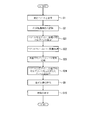
- the output frame H it is determined whether or not the motion of the predetermined objects Za and Z (a + 1) in the input frame Fa and the input frame F (a + 1) can be detected. This motion is acquired as the (a + 1) th input video detection vector V (a + 1) (hereinafter referred to as the input video detection vector V as appropriate). Further, the input frame F at the input synchronization timing at which the interval from the output synchronization timing of the predetermined output frame H is the shortest is recognized, and the interval between the output synchronization timing and the input synchronization timing is recognized as the interpolation distance.
- the interpolation distance ratio is a positive value when the output synchronization timing of the output frame H is close to the input synchronization timing of the previous input frame F, and is negative when the output synchronization timing of the subsequent input frame F is close. Value.
- the interpolation distance ratio is 0 when there is an input frame F having the same output synchronization timing as the output synchronization timing of the output frame H.
- the input frame F is applied as the output frame H. Further, when the interpolation distance ratio is a positive value and the input video detection vector V (a + 1) can be acquired, the input video detection vector V (a + 1) is multiplied by the interpolation distance ratio. The c-th input video use vector Jc is obtained. Then, an interpolation frame Gc in which the object Za has moved by an amount corresponding to the input video use vector Jc is generated for the input frame Fa and applied as the output frame H. On the other hand, when the interpolation distance ratio is a positive value and the input video detection vector V (a + 1) cannot be acquired, the input frame Fa and the input frame F (a + 1) are applied as they are as the output frame H. To do.
- the interpolation distance ratio is a negative value and the input video detection vector V (a + 1) can be acquired, the input video detection vector V (a + 1) is multiplied by the interpolation distance ratio. An input video use vector Jc is obtained. Then, an interpolation frame Gc in which the object Z (a + 1) is moved based on the input video use vector Jc is generated and applied as the output frame H.
- the interpolation distance ratio is a negative value and the input video detection vector V (a + 1) cannot be acquired, the input frame Fa and the input frame F (a + 1) are applied as they are as the output frame H. To do.
- the input frame F5 is applied as the output frame H11.
- the input video use vector J10 is obtained by multiplying the input video detection vector V6 by 1 which is the interpolation distance ratio, and the interpolation in which the object Z5 is moved by an amount corresponding to the input video use vector J10 with respect to the input frame F5.
- Frame G10 is applied as output frame H12.
- the input video use vector J11 is obtained by multiplying the input video detection vector V6 by the interpolation distance ratio -0.50, and the object Z6 moves by an amount corresponding to the input video use vector J11 with respect to the input frame F6.
- the interpolated frame G11 is applied as the output frame H13.
- Patent Document 1 describes a smoothed motion amount between the previous frame and the previous frame (hereinafter referred to as a motion amount between previous frames) and a provisional motion amount between the current frame and the previous frame. (Hereinafter, referred to as the amount of motion between the current frames), the amount of motion after smoothing between the current frame and the previous frame is calculated, and the smoothing between the calculated current frame and the previous frame is calculated.
- a configuration is adopted in which an expected image, that is, an interpolated frame is generated based on the later motion amount, and the frame rate is converted by outputting the interpolated frame as an output image.
- Patent Document 2 employs a configuration in which an interpolation frame is generated using a motion vector for a character region to be scrolled, and a linear interpolation process or a replacement process using a neighboring frame is performed for a region other than the character region. Yes.
- the following can be considered in the vector frame rate conversion technique as described above. That is, for example, as shown in FIG. 2, in the second state where the input video detection vector V7 cannot be acquired and the input video detection vectors V6, V8 and V9 can be acquired, the input frame F6 is the output frame H14. As a result, the input frame F7 is applied as the output frame H15. That is, the output frames H14 to H16 are non-smooth areas, and the frame rate conversion is performed so that the output frames H11 to H13 and the output frames H17 and later become smooth areas. For this reason, in the case as shown in FIG. 2, the difference between the non-smooth area and the smooth area is large, which may result in an unnatural output image. For example, as shown in FIG.
- an abnormal input video detection vector V7 whose end point does not coincide with the starting point of the input video detection vector V8 can be acquired, and normal input video detection vectors V6, V8, and V9 can be acquired.
- the input video use vectors J12 and J13 are obtained by multiplying the abnormal input video detection vector V7 by the interpolation distance ratio.
- the interpolation frames G12 and G13 are generated in which the objects Z6 and Z7 are moved by an amount corresponding to the input video use vectors J12 and J13, and the size is changed by an amount corresponding to the input video use vectors J12 and J13.
- output frames H14 and H15 become a video failure area having a large error from the actual motion of the video, and the video may be broken.
- an interpolated frame is generated based on the amount of motion between past frames and the amount of motion between current frames.
- the amount of motion between the frames is linearly independent, that is, when the vectors are not parallel, the amount of motion in the interpolated frame is distorted and may not match the actual motion of the output video.
- the scrolling character area detected in Patent Document 2 often moves at a higher speed than a general video.
- the faster the movement of the object the greater the change between frames and the more difficult it is to estimate the motion vector.
- Since the character area to be scrolled does not blur even if the motion is fast, the frame rate conversion by the motion vector functions effectively.
- the motion vector detection fails, the interpolation frame is easily broken. That is, the character area to be scrolled is a very special area, and it is necessary to increase the accuracy of the motion vector to be adapted. For this reason, the configuration as in Patent Document 2 requires a detection method specialized in the detection of a scrolling character area and the detection of its motion vector.
- An object of the present invention is to record a frame rate conversion device, an image processing device, a display device, a frame rate conversion method, a program thereof, and the program capable of appropriately performing a frame rate conversion process for interpolating an interpolated frame. It is to provide a recording medium.
- the frame rate conversion apparatus converts an input video composed of a plurality of input frames, which can be regarded as being input at an input synchronization timing based on an input image signal having a predetermined input frequency, into an output image signal having a predetermined output frequency.
- a frame rate conversion device for converting a frame rate into an output video composed of the input frame output at an output synchronization timing based on and an interpolated frame interpolated between the input frames.
- a vector acquisition unit that acquires a motion as a motion vector, the output synchronization timing at which the interpolation frame is output, and the interval of the input synchronization timing of the input frame that is used to generate the interpolation frame
- An interpolation distance detection unit that detects the distance
- a vector acquisition accuracy determination unit that determines whether continuity of the motion vector corresponding to each of the input frame and the input frame adjacent to the input frame is higher than a predetermined level
- the interpolation An interpolation frame vector is set by adjusting the magnitude of the motion vector of the input frame used for generating the interpolation frame based on the distance, and a first corresponding to the motion based on the interpolation frame vector
- a vector frame rate conversion processing unit that generates the interpolation frame, and linear interpolation processing of a pair of input frames corresponding to the input synchronization timing before and after the output synchronization timing at which the interpolation distance is detected.
- a weighted average frame rate conversion processing unit for generating a second interpolated frame; and a continuity of the motion vectors.
- An interpolation control unit for interpolating the first interpolation frame, and for interpolating the second interpolation frame when it is determined that the continuity is low.
- An image processing apparatus includes the above-described frame rate conversion apparatus, the input frame, the first interpolation frame, and the first frame constituting the output video in which the frame rate is converted by the frame rate conversion apparatus. And an appropriate video extracting device that extracts an area excluding at least a part of the periphery of at least one of the two interpolated frames as an output frame to be output at the output synchronization timing.
- a display device includes the above-described frame rate conversion device and a display unit that displays the output video whose frame rate has been converted by the frame rate conversion device.
- the display device of the present invention includes the output image including the output frame that has been converted by the above-described image processing device and the frame rate conversion device of the image processing device and has been extracted by the appropriate image extraction device. And a display unit for displaying.
- an input video composed of a plurality of input frames that can be considered to be input at an input synchronization timing based on an input image signal having a predetermined input frequency is calculated by an arithmetic unit.
- a frame rate conversion method for converting a frame rate to an output video composed of the input frame output at an output synchronization timing based on an output image signal and an interpolated frame interpolated between the input frames is calculated by an arithmetic unit.
- a vector acquisition accuracy determination step, and an interpolation frame vector is set by adjusting a magnitude of the motion vector of the input frame used for generating the interpolation frame based on the interpolation distance.
- a vector frame rate conversion process for generating a first interpolation frame corresponding to a motion based on a frame vector; and a pair of input synchronization timings corresponding to before and after the output synchronization timing at which the interpolation distance is detected Weighted average frame rate for generating the second interpolated frame by performing linear interpolation processing of the input frame If it is determined that the continuity of the motion vector is high, the first interpolation frame is interpolated. If it is determined that the continuity is low, the second interpolation frame is inserted. And an interpolation control step of inserting.
- the frame rate conversion program of the present invention is characterized by causing a calculation means to execute the above frame rate conversion method.
- the frame rate conversion program of the present invention is characterized in that the calculation means functions as the above-described frame rate conversion device.
- the recording medium on which the frame rate conversion program of the present invention is recorded is characterized in that the above-described frame rate conversion program is recorded so as to be readable by the calculation means.
- 1 is a block diagram illustrating a schematic configuration of a display device according to a first embodiment of the present invention.
- the display device includes the frame rate conversion device of the present invention, and the frame rate of an input video composed of a plurality of input frames input from the outside is set.
- a configuration for displaying the converted output video will be described as an example.
- symbol are attached
- FIG. 4 is a block diagram illustrating a schematic configuration of the display device.
- FIG. 5 is a schematic diagram illustrating a generation state of the first and second interpolation frames when the input image detection vector acquisition state is the second state.
- FIG. 6 is a schematic diagram illustrating a generation state of the first and second interpolation frames when the input image detection vector acquisition state is the third state.
- FIG. 7 is a schematic diagram showing a frame rate conversion state when the input image detection vector acquisition state is the second state.
- FIG. 8 is a schematic diagram showing a frame rate conversion state when the input image detection vector acquisition state is the third state.
- FIG. 9 is a schematic diagram illustrating a generation state of the interpolation frame.
- FIG. 10 is a schematic diagram showing an output frame extraction state.
- FIG. 11 is a schematic diagram showing another extraction state of the output frame.
- 12 to 17 are schematic diagrams showing display states of output frames.
- the display device 100 includes a display unit 110 and an image processing device 120.
- the display unit 110 is connected to the image processing apparatus 120.
- the display unit 110 displays the output video with the frame rate converted under the control of the image processing apparatus 120.
- Examples of the display unit 110 include a PDP (Plasma Display Panel), a liquid crystal panel, an organic EL (Electro Luminescence) panel, a CRT (Cathode-Ray Tube), an FED (Field Emission Display), and an electrophoretic display panel.
- the image processing device 120 includes a frame rate conversion device 130 as an arithmetic means and an appropriate video extraction device 140.
- the frame rate conversion apparatus 130 includes a frame memory 131, a vector acquisition unit 133, a vector acquisition accuracy determination unit 134, an interpolation distance ratio recognition unit 135 as an interpolation distance detection unit, A frame rate conversion processing unit 136, a weighted average frame rate conversion processing unit 137, and an interpolation control unit 138 are provided.
- the frame memory 131 acquires an image signal from the image signal output unit 10, temporarily stores an input frame F (see, for example, FIG. 5) based on the image signal, and a vector acquisition unit 133, vector frame rate conversion The data is appropriately output to the processing unit 136 and the weighted average frame rate conversion processing unit 137.
- the vector acquisition unit 133 acquires the input frame F (a + 1) based on the image signal from the image signal output unit 10 and the input frame Fa temporarily stored in the frame memory 131. Then, the motion of the input frames F (a + 1) and Fa is used as an input video detection vector V (a + 1) as a first motion vector and a local area vector (not shown) as a second motion vector. get.
- the vector acquisition unit 133 when acquiring the input video detection vector V (a + 1), the vector acquisition unit 133 is configured by a portion other than a portion inside a predetermined distance from an outer edge (not shown) of the input frame F (a + 1).
- One motion detection block to be set is set. This motion detection block is composed of a plurality of local areas divided into a plurality. That is, the motion detection block has a first block size made up of a first number of pixels (not shown).
- the vector acquisition unit 133 converts the motion in the motion detection block, that is, the motion in almost the entire input frame F (a + 1), to one input video detection vector V (a +1) and output to the vector acquisition accuracy determination unit 134 and the vector frame rate conversion processing unit 136.
- a method for obtaining the input video detection vector V (a + 1) for example, a method described in Japanese Patent Publication No. 62-62109 (hereinafter referred to as a pattern matching method) or Japanese Patent Application Laid-Open No. 62-206980. Examples thereof include a method as described in the publication (hereinafter referred to as iterative gradient method). That is, when the pattern matching method is used, a plurality of blocks (hereinafter referred to as the following) having the same number of pixels as the motion detection block of the input frame F (a + 1) and shifted in different directions with respect to the input frame Fa. Set as “Past block”.
- a block having the highest correlation with the motion detection block is detected from the plurality of past blocks, and an input video detection vector V (a + 1) is acquired based on the detected past block and motion detection block.
- the optimum one for detecting the input video detection vector V (a + 1) is selected as the initial displacement vector. Then, by starting the calculation from a value close to the true input video detection vector V (a + 1) of the motion detection block, the number of times of the gradient method calculation is reduced, and the true input video detection vector V (a + 1) is detected.
- the vector acquisition unit 133 acquires the motion in each local area as a local area vector, and outputs it to the vector acquisition accuracy determination unit 134. That is, the motion in the local area composed of the second number of pixels smaller than the first number is detected.
- the same processing as that for acquiring the input video detection vector V (a + 1) is performed. Note that, as the local area vector acquisition process, a process different from that for acquiring the input video detection vector V (a + 1) may be applied.
- the vector acquisition accuracy determination unit 134 determines the acquisition accuracy of the input video detection vector V acquired by the vector acquisition unit 133. Specifically, when the vector acquisition unit 133 cannot acquire the input video detection vector V, the vector acquisition accuracy determination unit 134 determines that the input video detection vector V is not continuous, that is, lower than a predetermined level. Further, when the input video detection vector V can be acquired and the number of local area vectors matching the input video detection vector V is equal to or greater than a threshold value, the input video detection vector V is continuous, that is, higher than a predetermined level. Judge. If the number of local area vectors matching the input video detection vector V is less than the threshold value, it is determined that there is no continuity of the input video detection vector V.
- the vector acquisition accuracy determination unit 134 outputs an output selection signal for outputting the interpolation frame Gc generated by the vector frame rate conversion processing unit 136 when the acquisition accuracy of the input video detection vector V is higher than a predetermined level.
- the second interpolation frame M generated by the weighted average frame rate conversion processing unit 137 (hereinafter, the c-th second interpolation frame is appropriately selected).
- An output selection signal for outputting the second interpolation frame Mc) is output to the interpolation control unit 138.
- the vector acquisition accuracy determination unit 134 may determine the acquisition accuracy of the input video detection vector V as follows. That is, when the vector acquisition unit 133 cannot acquire the input video detection vector V, it is determined that the input video detection vector V is not continuous and the acquisition accuracy is low. If the input video detection vector V can be acquired, the variance of the local area vector is calculated. If this variance is less than or equal to the threshold, it is determined that the input video detection vector V is continuous and the acquisition accuracy is high, and if it is greater than the threshold, the input video detection vector V is not continuous and the acquisition accuracy is low. May be.
- the interpolation distance ratio recognition unit 135 acquires the input vertical synchronization signal of the input frame F and the output vertical synchronization signal of the output frame H from the synchronization signal output unit 20, and performs the same processing as that of the conventional vector frame rate conversion technique described above. To calculate and recognize an interpolation distance ratio based on the interpolation distance. That is, the interpolation distance ratio recognition unit 135 recognizes the input frame F at the input synchronization timing at which the interval from the output synchronization timing of the predetermined output frame H is the shortest, and determines the interpolation distance that is the interval as the output synchronization timing. The value divided by the interval is calculated as the interpolation distance ratio. For example, as shown in FIGS.
- the interpolation distance ratio recognition unit 135 outputs the interpolation distance ratio to the vector frame rate conversion processing unit 136 and the weighted average frame rate conversion processing unit 137.
- the vector frame rate conversion processing unit 136 performs a process as shown in FIG. 1 to obtain an interpolation frame Gc (first interpolation in the first embodiment). (Referred to as frame Gc) and output to interpolation control section 138. That is, when the interpolation distance ratio is 0, the input frame F is applied as the first interpolation frame Gc. Further, when the interpolation distance ratio is a positive value and the input video detection vector V (a + 1) can be acquired, the input video detection vector V (a + 1) is multiplied by the interpolation distance ratio. An input video use vector Jc is obtained.
- a first interpolation frame Gc in which the object Z has moved by an amount corresponding to the input video use vector Jc is generated with respect to the input frame Fa. Further, when the interpolation distance ratio is a negative value and the input video detection vector V (a + 1) can be acquired, the input frame F (a + 1) is based on the input video use vector Jc. A first interpolation frame Gc in which the object Z has moved is generated.
- the weighted average frame rate conversion processing unit 137 generates the second interpolation frame Mc by executing linear interpolation processing based on the interpolation distance ratio. Specifically, the weighted average frame rate conversion processing unit 137 calculates the reference plane weighted average weight and the target plane weighted average weight by substituting the interpolation distance ratio into the following formulas (1) and (2). .
- the weighted average frame rate conversion processing unit 137 interpolates between the input frame Fa and the input frame F (a + 1) based on the reference plane weighted average weight and the target plane weighted average weight.
- An interpolation frame Mc is generated. Specifically, when the interpolation distance ratio corresponding to the second interpolation frame Mc is a positive value, the reference plane frame corresponding to the second interpolation frame Mc is recognized as the past input frame Fa. To do.
- the reference plane frame “P” represents that the reference plane frame is set to the past input frame Fa
- “U” represents the future input frame F (a + Indicates that it is set in 1).
- the weighted average frame rate conversion processing unit 137 uses the color of each pixel at the corresponding position in the input frame Fa and the input frame F (a + 1) as the color of the predetermined pixel in the second interpolation frame Mc. Are mixed in proportions corresponding to the reference surface weighted average weight and the target surface weighted average weight, respectively.
- the reference plane frame corresponding to the second interpolation frame Mc is the future input frame F (a + 1).
- the predetermined pixel color in the second interpolation frame Mc the color of each pixel at the corresponding position in the input frame F (a + 1) and the input frame Fa is used as the reference plane weighted average weight. And the color mixed by the ratio respectively corresponding to an object surface weighted average weight is applied.
- the weighted average frame rate conversion processing unit 137 inserts the second interpolation frame M12 to be inserted at a position close to the input frame F6 between the input frame F6 and the input frame F7.
- the input frame F6 is recognized as the reference plane frame of the second interpolation frame M12, and the color of the object Z6 and the input frame as the color of the corresponding position of the object Z6 on the second interpolation frame M12.
- a color mixed at a ratio of 0.8: 0.2 with the color at the corresponding position on F7 is applied.
- the mixing ratio of the color of the corresponding position on the input frame F6 and the color of the object Z7 is mixed at 0.8: 0.2. Apply the selected color.
- the input frame F7 is recognized as the reference plane frame of the second interpolation frame M13, and the color of the corresponding position of the object Z6.
- a color at a position corresponding to the object Z7 a color obtained by mixing the color of the corresponding position on the input frame F7 and the color of the object Z6 with a mixing ratio of 0.6: 0.4 is applied.
- a color in which the mixing ratio of the color of Z7 and the color at the corresponding position on the input frame F6 is 0.6: 0.4 is applied.
- the vector frame rate conversion processing unit 136 and the weighted average frame rate conversion processing unit 137 use the input frame F acquired immediately before to obtain the first interpolation frame Gc and A second interpolation frame Mc is generated. That is, the vector frame rate conversion processing unit 136 generates and outputs a first interpolation frame Gc (not shown) at a timing corresponding to the second interpolation frames M12 and M13, and the weighted average frame rate conversion processing unit 137 The second interpolation frame Mc (not shown) at the timing corresponding to the first interpolation frames G10, G11, G14 to G17 is generated and output.
- the interpolation control unit 138 receives the output selection signal from the vector acquisition accuracy determination unit 134, the first interpolation frame Gc from the vector frame rate conversion processing unit 136, and the second from the weighted average frame rate conversion processing unit 137. Of the interpolated frame Mc. Based on the output selection signal, one of the first interpolation frame Gc and the second interpolation frame Mc is output to the appropriate video extraction device 140. For example, in the cases shown in FIGS. 5 and 6, since the interpolation distance ratio of the input frames F5, F7, and F9 is 0, the input frames F5, F7, and F9 are output frames H that are displayed on the display unit 110. The video is output to the appropriate video extraction device 140.
- the output frame H is displayed at the timing between the input frame F5 and the input frame F6 and at the timing between the input frame F7 and the input frame F9.
- the first interpolation frames G10, G11, G14 to G17 are output to the appropriate video extraction device 140.
- the acquisition accuracy of the input video detection vector V7 is low, or the input video detection vector V7 has not been acquired, so the timing between the input frame F6 and the input frame F7.
- the second interpolation frames M12 and M13 are output to the appropriate video extraction device 140.
- the input frame F9 is appropriately processed by the appropriate video extraction device 140 and displayed on the display unit 110 as output frames H11 to H21 as shown in FIGS. 7 illustrates the output frame H when the input frame F illustrated in FIG. 5 is input, and FIG. 8 illustrates the output frame H when the input frame F illustrated in FIG. 6 is input. Yes.
- the first interpolation frame Gc to be displayed as the output frame H is partly deleted in the appropriate video extraction device 140 as necessary and displayed on the display unit 110 as described later.
- FIGS. 7 and 8, FIGS. 27 to 32, and FIGS. 41 to 46, which will be described later, illustrate a state in which a part is not deleted.
- the appropriate video extraction device 140 deletes a part of the periphery of the first interpolation frame Gc to be displayed as the output frame H as necessary, and causes the display unit 110 to display an appropriate image.
- the first interpolation frame G110 having an interpolation distance ratio of 1 with respect to the input frame F105 is made appropriate based on the input frames F105 and F106 input at 24 Hz will be described as an example.
- a first interpolation frame G110 based on the input frames F105 and F106 is generated and output from the interpolation control unit 138.
- the objects Z105A and Z105B of the input frame F105 are set to 0. 0 along the input video detection vector V106.
- Objects Z110A and Z110B exist at positions moved by four.
- the image of the input frame F105 can be used as it is for a portion other than the left end portion and the lower end portion in the first interpolation frame G110.
- the image of the input frame F105 cannot be used for the left end portion and the lower end portion.
- the left end portion and the lower end portion illustrated by hatching become a substituted image display region W110 in which a substituted image generated without using the input frame F is displayed.
- the substitution image as shown in FIG. 9, an image obtained by continuously copying the colors of the left end and the bottom end of the input frame F105 to the right side and the upper side as it is, A white image can be exemplified.
- the appropriate video extraction device 140 performs a region surrounded by a one-dot chain line excluding all of the substitution image display region W110 in the first interpolation frame G110, that is, the first interpolation frame.
- a region excluding the left end portion and the lower end portion in G110 is extracted as an output frame H112 and output to the display unit 110.
- an area including a part of the substitution image display area W110 is excluded except for a part that enters a predetermined distance from the upper end, the lower end, the right end, and the left end in the first interpolation frame G110.
- the output frame H112 may be extracted and output to the display unit 110.
- the display unit 110 displays the input frame F105 as the output frame H111 as shown in FIG.
- an output frame H112 is displayed as shown in FIG.
- an input frame F107 is displayed as an output frame H116 as shown in FIG. That is, the output frame H112 smaller than the output frames H111 and H116 is displayed such that the upper right end thereof coincides with the upper right end of the output frames H111 and H116.
- the display unit 110 displays the output frames H111, H112, and H116 as shown in FIGS. That is, the output frame H112 that is smaller than the output frames H111 and H116 and includes a part of the substitution image display area W110 is displayed so that the center thereof coincides with the centers of the output frames H111 and H116.
- the interpolation distance ratio recognition unit 135 recognizes the input frame F at the input synchronization timing at which the interval from the output synchronization timing of the predetermined output frame H is the shortest, and calculates it as the interpolation distance ratio.
- motion compensation processing is executed on the objects Z105A and Z105B of the input frame F105. Cannot use the image of the input frame F105.
- the motion compensation process is performed on the objects Z106A and Z106B of the input frame F106.
- the area where the image of the input frame F106 cannot be used is a right end portion and an upper end portion facing the left end portion and the lower end portion shown by hatching in FIG.
- the first interpolation frame G is created by the motion compensation process using the motion vector
- an area where the image of the input frame F cannot be used is generated at the periphery of the frame.
- the size of this area is determined by the size of the detected motion vector.
- the size of the motion vector is increased, that is, if the speed of the object is increased, detection of the motion vector becomes difficult, and the human eye cannot follow. Therefore, it is sufficient that the motion vector can be detected to the extent that the human eye can follow. Therefore, we evaluated how far the human eye can follow the movement of the screen as follows.
- the video used is a natural picture that moves from left to right and a natural picture that moves from top to bottom.
- the screen when the time required for the object to move in the horizontal direction or the vertical direction of one screen is 5 seconds was used as the reference screen.
- a state in which the movement of the object can be sufficiently followed was evaluated as 5.
- a state where it can follow the movement of the object at the edge of the screen if it is concentrated is set as evaluation 4.
- evaluation 3 is a state in which the movement of the object at the center of the screen can follow the movement of the object at the center of the screen even though the movement at the edge of the screen cannot be followed.
- the screen edge means the top, bottom, left and right peripheral portions of 5% of the horizontal length or vertical length of the screen.
- evaluation 2 a state where it was not possible to follow the movement of the object in the center of the screen was set as evaluation 2. That is, the average value of the evaluation is 2 when all 10 subjects cannot follow the movement of the object in the center of the screen. In a state where even one of the ten people can follow the movement of the object, the average value of the evaluation is greater than two.
- Tables 1 and 2 show average values of the evaluation results of 10 subjects on the screen in which the object moves from left to right.
- Table 3 and Table 4 show the average values of the evaluation results of 10 subjects on the screen in which the object moves from top to bottom.
- the first index is a state in which the evaluation of 10 subjects is evaluation 2, that is, all 10 subjects cannot follow the movement of the object in the center of the screen (1 out of 10 people can follow the movement of the object).
- the second index is a state in which the average of the evaluations of 10 subjects is evaluation 3, that is, the average can follow the movement of the object in the center of the screen. From the results of Tables 1 to 4, the state of the first index indicates that the movement amount between frames is 10% of the horizontal length or vertical length of one frame, and the state of the second index is between frames. The amount of movement was 5% of the horizontal length or vertical length of one frame.
- the maximum value of the movement amount between frames is 10% of the horizontal length or vertical length of one frame, and when considered based on the second index, The maximum value of the movement amount was 5% of the horizontal length or vertical length of one frame. If the amount of movement exceeds this, the viewer cannot follow the movement of the object, which means that it is not necessary to consider such a range.
- the interpolation distance ratio recognition unit 135 performs the motion compensation process on the object of the input frame F at the input synchronization timing at which the interval from the output synchronization timing of the predetermined output frame H is the shortest.
- the area where the image of the frame F cannot be used is further 1 ⁇ 2 of the above maximum value. That is, when the first index is used, the maximum value of the moving range of one frame with respect to the horizontal length of one frame or the vertical length in a limit state where one in ten people can follow the movement of the object.
- the area where the image of the input frame F cannot be used is the upper, lower, left and right peripheral areas of each frame, and the width of each area is 5% of the horizontal length or vertical length of one frame.
- the area where the image of the input frame F cannot be used is the peripheral area of the top, bottom, left, and right of each frame, and each width is 2.5% of the horizontal length or vertical length of one frame.
- This value is a case where the first interpolation frame G is created from the two input frames F at positions where the interpolation distances are equal. This is the case when frame conversion is performed from an input frame F having a vertical frequency of 60 Hz to a frame having a vertical frequency of 120 Hz.
- the appropriate video extraction device 140 is an area where the image of the input frame F cannot be used, that is, the upper, lower, left and right peripheral areas, and each frame has a horizontal length, a maximum length of 5% or a maximum length. An area excluding the 2.5% area is extracted as an output frame H and output to the display unit 110.
- the position is set to 2: 3 or 3: 2 with respect to the distance between adjacent input frames F. Since the first interpolation frame G is created, the area where the image of the input frame F cannot be used is the movement of one frame with respect to the horizontal length or vertical length of one frame in the first index described above. 0.4% of the maximum value 10% of the range, 4%, and in the second index, 2 times 0.4 of the maximum value 5% of the moving range of 1 frame with respect to the horizontal length or vertical length of one frame %.
- the appropriate video extraction device 140 is an area where the image of the input frame F cannot be used, that is, the upper, lower, left, and right peripheral areas, and each frame has a horizontal length, a maximum of 4% of a vertical length, or a maximum An area excluding the 2% area is extracted as an output frame H and output to the display unit 110.
- the image processing apparatus of the present application includes a frame rate conversion apparatus that converts the number of frames of the image signal by interpolating the image signal subjected to the motion compensation process between the frames of the input video signal, and the frame rate. And an appropriate video extraction device for extracting the video output signal of a frame excluding at least a part of a peripheral area in the frame of the output video signal whose number of frames has been converted by the conversion device.
- the appropriate video extraction device may determine the size of the area to be excluded by the motion compensation process when the magnitude of the motion detected by the motion compensation process is greater than a predetermined level.
- the output video signal set to be larger than the size of the excluded area when the size is a predetermined level or less can be extracted.
- two adjacent frames of the input video signal are used as past frames and future frames, and motion compensation processing is performed between the two frames using the motion vectors obtained by these two frames and the past frames.
- motion compensation processing is performed between the two frames using the motion vectors obtained by these two frames and the past frames.
- the motion detected by the motion compensation processing is When the right motion component is larger than a predetermined value, the right motion component is less than a predetermined level.
- the width is preferably set to be equal to or larger than the width of the excluded region.
- the upper movement component When the magnitude is larger than a predetermined value, it is preferable to set the upper movement component to be equal to or larger than the width of the excluded area when the magnitude of the upper motion component is equal to or lower than a predetermined level. Further, when an interpolation frame is created by performing motion compensation processing between the two frames using the motion vector obtained by the two frames and the future frame, the motion detected by the motion compensation processing is increased.
- the upper movement component is larger than a predetermined value
- the upper movement component size is less than a predetermined level except for the upper peripheral region of the frame.
- the width is preferably set to be equal to or larger than the width of the excluded region.
- the image processing apparatus can determine that the excluded area is the number of pixels arranged in parallel in the frame of the output video signal. It is preferable that it is a maximum of 5% or less of the number and the left or right peripheral edge of the frame.
- the excluded area is preferably 5% or less of the number of pixels arranged in parallel in the frame of the output video signal and the upper or lower peripheral edge of the frame.
- the image processing device is configured such that the excluded area is the maximum number of pixels arranged in parallel in the frame of the output video signal. It is preferably 2.5% or less and the left or right peripheral edge of the frame. The excluded area is preferably 2.5% or less of the number of vertically arranged pixels in the frame of the output video signal and the upper or lower peripheral edge of the frame.
- linear interpolation processing can be used in the peripheral area of the frame. .
- the video signal created by motion compensation processing and linear interpolation processing is ⁇ -blended, and the blend ratio is gradually changed in one frame, so that linear interpolation processing is performed in the peripheral region of the frame, and motion compensation is performed in the central region of the frame. Processing, between the peripheral area and the central area, the video signal created by motion compensation processing and linear interpolation processing is ⁇ blended, and the blending ratio of the ⁇ blend is gradually changed spatially, and the video signal of the adjacent region Can be ensured.
- FIG. 18 is a flowchart showing the operation of the display device.
- the frame rate conversion device 130 of the display device 100 acquires the image signal from the image signal output unit 10 and the input vertical synchronization signal and output vertical synchronization signal from the synchronization signal output unit 20, as shown in FIG.
- the input video detection vector V and the local area vector are acquired (step S1).
- the interpolation distance ratio is recognized based on the input vertical synchronization signal, the output vertical synchronization signal, and the like (step S2).
- the acquisition accuracy of the input video detection vector V is determined (step S3).
- the frame rate conversion device 130 generates a first interpolation frame Gc by vector frame rate conversion processing (step S4), and generates a second interpolation frame Mc by weighted average frame rate conversion processing (step S4). S5).
- the frame rate conversion apparatus 130 determines whether or not the acquisition accuracy of the input video detection vector V is higher than a predetermined level (step S6). If it is determined in step S6 that the frame is high, the first interpolation frame Gc is output to the appropriate video extraction device 140 (step S7). If it is determined that the frame is low, the second interpolation frame Mc is output (step S7). S8).
- the output video when the acquisition state of the input video detection vector V as shown in FIGS. 2 and 3 is in the second and third states is as shown in FIGS.
- output frames H11 to H13 generated by vector frame rate conversion, and output frames H14 and H21 generated by weighted average frame rate conversion between output frames H16 and H21, H15 is displayed.
- the positions of the objects Z6 and Z7 do not follow the vector corresponding line T, but the color of the object Z6 gradually fades and the object Z6 disappears, and the color of the object Z7 gradually darkens.
- An image in which Z7 appears is smoother than in the case of FIGS.
- the appropriate video extraction device 140 of the display device 100 acquires the first interpolation frame Gc and the second interpolation frame Mc from the frame rate conversion device 130, the output frame H is output from the first interpolation frame Gc. Is extracted as necessary, that is, an appropriate video is extracted (step S9). And the display part 110 of the display apparatus 100 displays the image
- the frame rate conversion device 130 of the display device 100 detects a motion for each input frame F and acquires it as an input video detection vector V. Further, the interpolation distance ratio is calculated by dividing the interpolation distance that is the interval between the output synchronization timing of the predetermined output frame H and the input synchronization timing of the predetermined input frame F by the interval of the output synchronization timing. Then, the input video use vector J is set by multiplying the interpolation distance ratio and the input video detection vector V, and a first interpolation frame G of the motion amount based on the input video use vector J is generated. .
- the reference plane weighted average weight and the target plane weighted average weight are calculated based on the above formulas (1) and (2), and each of the corresponding positions in the input frame Fa and the input frame F (a + 1) is calculated.
- a second interpolation frame M is generated in which the color of the pixel is set to a color obtained by mixing the reference surface weighted average weight and the target surface weighted average weight at a ratio corresponding to each. Then, when the acquisition accuracy of the input video detection vector V is high, the first interpolation frame G is output, and when it is low, the second interpolation frame M is output. Therefore, as shown in FIG.
- both the objects Z6 and Z7 of the input frames F6 and F7 exist in the non-smooth area where only the object Z6 or the object Z7 in FIG.
- the second interpolation frame M12 in which the color of the object Z6 is darker than the object Z7 and the second interpolation frame M13 in which the color of the object Z7 is darker than the object Z6 can be displayed. Further, as shown in FIG. 8, the above-described second interpolation frames M12 and M13 can be displayed in the video failure area in FIG. Therefore, as compared with the conventional configuration as shown in FIGS. 2 and 3, the movement of the object Z can be smoothed, and a natural output video can be displayed.
- the first interpolation frame G is output, so that the second interpolation frame M is output regardless of the acquisition accuracy of the input video detection vector V.
- the movement of the object Z can be made smoother than the above configuration.
- the input frame F at the input synchronization timing that has the shortest interval from the output synchronization timing of the predetermined output frame H is recognized, and the interpolation distance ratio is calculated based on the interpolation distance that is the interval. That is, for example, as shown in FIG. 5, when the first interpolation frame G15 corresponding to the output frame H18 is generated, the interpolation distance ratio is calculated based on the input frame F8 instead of the input frame F7. For this reason, for example, when generating the first interpolation frame G15, the size of the input video use vector J15 is set as compared with the case where the input video use vector J15 based on the interpolation distance ratio corresponding to the input frame F7 is used. Can be small. That is, the amount of movement of the object Z15 relative to the input frame F8 can be reduced. Therefore, the processing load at the time of generating the first interpolation frame G15 can be reduced.
- the appropriate video extraction device 140 extracts an area excluding at least a part of the periphery of the first interpolation frame G as an output frame H, and causes the display unit 110 to display the output frame H. For this reason, the display of the substitution image display area W provided in the first interpolation frame G can be eliminated, the display amount can be minimized, and a natural output video can be displayed.
- FIG. 19 is a block diagram illustrating a schematic configuration of the display device.
- FIG. 20 is a schematic diagram showing setting control of the vector correspondence gain and the weighted average correspondence gain.
- FIG. 21 and FIG. 22 are schematic diagrams showing the generation states of the first and second interpolation frames when the input image detection vector acquisition state is the fourth state.
- FIG. 23 and FIG. 24 are schematic diagrams showing the generation states of the first and second interpolation frames when the input image detection vector acquisition state is the fifth state.
- FIG. 25 and FIG. 26 are schematic diagrams showing the generation states of the first and second interpolation frames when the acquisition state of the input video detection vector is the sixth state.
- 27 and 28 are schematic diagrams illustrating a frame rate conversion state when the input video detection vector acquisition state is the fourth state.
- FIG. 29 and FIG. 30 are schematic diagrams showing a frame rate conversion state when the input image detection vector acquisition state is the fifth state.
- FIG. 31 and FIG. 32 are schematic diagrams showing a frame rate conversion state when the input image detection vector acquisition state is the sixth state.
- the display device 200 includes a display unit 110 and an image processing device 220. Further, the image processing device 220 includes a frame rate conversion device 230 as an arithmetic unit and a proper video extraction device 140. Furthermore, the frame rate conversion device 230 includes a frame memory 131, a vector acquisition unit 133, a gain control unit 234 that also functions as a vector acquisition accuracy determination unit, an interpolation distance ratio recognition unit 135, which are configured from various programs. A vector frame rate conversion processing unit 236, a weighted average frame rate conversion processing unit 237, and an interpolation control unit 238.
- the gain control unit 234 Based on the continuity of the input video detection vector V acquired by the vector acquisition unit 133, the gain control unit 234, as shown in FIG.
- the corresponding gain is increased or decreased by 0.25 in the range from 0 to 1.
- at least one of the vector-corresponding gain and the weighted average-corresponding gain is always increased or decreased so as to be zero.
- the initial set values of the vector correspondence gain and the weighted average correspondence gain are not limited to 1 and may be 0 or 0.5.
- the increase / decrease amount of the vector correspondence gain and the weighted average correspondence gain is not limited to 0.25, and may be 0.1 or 0.5. And you may increase / decrease in the state from which the quantity to increase and the quantity to reduce differ. Furthermore, the increase / decrease amount may be made different between the vector-corresponding gain and the weighted average-corresponding gain.
- the gain control unit 234 determines the acquisition accuracy of the input video detection vector V by the same processing as the vector acquisition accuracy determination unit 134 of the first embodiment. Then, when the acquisition accuracy is high, it is determined whether or not the weighted average correspondence gain can be reduced. When it is determined that the weighted average corresponding gain can be reduced because it is greater than 0, the weighted average corresponding gain is decreased by 0.25. On the other hand, if it is determined that the weighted average correspondence gain is 0 and cannot be reduced, the vector correspondence gain and the weighted average correspondence gain are maintained at 0 for one output frame H, and then the vector correspondence gain is set to 0. 0. Increase by 25.
- the gain control unit 234 determines whether or not the vector correspondence gain can be reduced. When the gain control unit 234 determines that the vector correspondence gain is larger than 0, the vector control gain is set to 0.25. If it is determined that it cannot be reduced because it is 0, the weight corresponding to the vector and the weighted average corresponding gain are maintained at 0 for one output frame H, and then the weighted average corresponding gain is increased by 0.25. . When the vector correspondence gain or the weighted average correspondence gain is 1, when it is determined to increase these, the state of 1 is maintained. Then, the gain control unit 234 outputs the vector corresponding gain to the vector frame rate conversion processing unit 236 and outputs the weighted average corresponding gain to the weighted average frame rate conversion processing unit 237.
- the gain control unit 234 shifts from the state where the acquisition accuracy of the input video detection vector V is lower than the predetermined level to the higher state, so that the vector frame rate conversion processing unit 236 is obtained when the weighted average correspondence gain becomes zero.
- the interpolation control unit 238 outputs an output selection signal indicating that the first interpolation frame L (hereinafter, the c-th first interpolation frame is referred to as the first interpolation frame Lc as appropriate) generated in step S1. Output to.
- the second interpolation generated by the weighted average frame rate conversion processing unit 237 when the weighted average corresponding gain becomes greater than 0 by shifting from a state where the acquisition accuracy is higher than a predetermined level to a lower state.
- An output selection signal for outputting the frame Mc is output to the interpolation control unit 238.
- the vector frame rate conversion processing unit 236 obtains the first gain by multiplying the interpolation distance ratio and the vector corresponding gain. Then, the input video use vector Kc (c is a natural number) is set by multiplying the input video detection vector V (a + 1) by the first gain. For example, as shown in FIG. 21, when the first gain corresponding to the output frame H19 (see FIG. 27) is 0.25, the input video is multiplied by 0.25 and the input video detection vector V9. A use vector K19 is set.
- the input video use vector J19 larger than the input video use vector K19 is set by multiplying the interpolation distance ratio 0.5 by the input video detection vector V9.
- the input video use vector Jc in which the magnitude of the input video detection vector V (a + 1) is adjusted based on the interpolation distance ratio is set.
- an input video use vector Kc in which the magnitude of the input video detection vector V (a + 1) is adjusted based on the interpolation distance ratio and the vector corresponding gain is set.
- the vector frame rate conversion processing unit 236 generates a first interpolation frame Lc in which the object Z has moved based on the input video use vector Kc.
- a first interpolation frame L19 in which the object Z8 of the input frame F8 is moved based on the input video use vector K19 is generated.
- the first interpolation frame G19 in which the object Z8 is moved corresponding to the input video use vector J19 larger than the input video use vector K19 is generated.
- the position of the object Z19 in the first interpolation frame L19 is closer to the position in the input frame F8 than the position in the first interpolation frame G19.
- the vector frame rate conversion processing unit 236 outputs the generated first interpolation frame Lc to the interpolation control unit 238.
- the input frame F having the closest output synchronization timing to the output synchronization timing of the output frame H is output to the interpolation control unit 238 as the first interpolation frame Lc. .
- the weighted average frame rate conversion processing unit 237 generates a second interpolation frame Mc based on the weighted average correspondence gain. Specifically, the weighted average frame rate conversion processing unit 237 calculates the second gain by multiplying the absolute value of the interpolation distance ratio and the weighted average corresponding gain. Then, the reference surface weighted average weight and the target surface weighted average weight are calculated by substituting the second gain into the following equations (3) and (4).
- the weighted average frame rate conversion processing unit 237 performs the same processing as the weighted average frame rate conversion processing unit 237 of the first embodiment, and generates a second interpolation frame Mc. That is, when the interpolation distance ratio is a positive value, an image in which the colors of the pixels in the input frame Fa and the input frame F (a + 1) are mixed with a mixture ratio based on the reference surface weighted average weight and the target surface weighted average weight. As the second interpolation frame Mc, and in the case of a negative value, the pixels in the input frame F (a + 1) and the input frame Fa with a mixture ratio based on the reference surface weighted average weight and the target surface weighted average weight Is generated as a second interpolation frame Mc.
- the reference plane weighted average The weight is 0.85 and the target surface weighted average weight is 0.15.
- the reference plane weighted average weight is 0.80, and the target The surface weighted average weight is 0.20.
- the vector frame rate conversion processing unit 236 and the weighted average frame rate conversion processing unit 237 use the input frame F acquired immediately before, to obtain the first interpolation frame Lc and A second interpolation frame Mc is generated.
- the interpolation control unit 238 receives the first interpolation frame Lc from the vector frame rate conversion processing unit 236 and the second average from the weighted average frame rate conversion processing unit 237.
- One of the interpolated frames Mc is output to the appropriate video extracting device 140.
- the acquisition state of the input video detection vector V as shown in FIGS. 21 and 22 is the fourth state
- the acquisition state is the fifth state as shown in FIGS. 23 and 24, it is shown in FIGS.
- the input frames F5, F7, F9, F11, and F13 are output to the appropriate video extraction device 140.
- an input frame F having a small interpolation distance ratio is output to the appropriate video extracting device 140.
- the vector-corresponding gain is 0 at the timing between the input frame F5 and the input frame F7. Therefore, as the output frame H displayed at this timing, The insertion frames M14 to M17 are output to the appropriate video extraction device 140. Further, since the weighted average correspondence gain is 0 at the timing between the input frame F7 and the input frame F13, the first interpolation frames L18 to L28 are output to the appropriate video extraction device 140. In the cases shown in FIGS. 23 and 24, since the weighted average corresponding gain is 0 at the timing between the input frame F5 and the input frame F7, the first interpolation frames L14 to L17 are appropriately extracted. Output to device 140.
- the second interpolation frames M18 to M28 are output to the appropriate video extraction device 140.
- the weighted average corresponding gain is 0 at the timing between the input frame F5 and the input frame F6, and therefore the first interpolation frames L14 and L15 are extracted as appropriate images. Output to device 140.
- the weighted average correspondence gain is 0, but the input video detection vector V7 cannot be acquired. For this reason, the first interpolation frame L cannot be generated, and the input frames F 6 and F 7 are output to the appropriate video extraction device 140.
- the vector-corresponding gain is 0 at the timing between the input frame F7 and the input frame F13, the second interpolation frames M18 to M28 are output to the appropriate video extraction device 140.
- the input frame F, the first interpolation frame Lc, and the second interpolation frame Mc output from the interpolation control unit 238 are appropriately processed by the appropriate video extraction device 140, and are shown in FIGS. As shown, it is displayed on the display unit 110 as output frames H11 to H31.
- FIGS. 27 to 32 correspond to FIGS. 21 to 26, respectively.
- FIGS. 27 and 28 show FIGS. 29 and 30 when the acquisition state of the input video detection vector V is the fourth state.
- FIG. 31 and FIG. 32 illustrate an output frame in the sixth state when in the fifth state.
- the appropriate video extraction device 140 deletes a part of the periphery of the first interpolation frame Lc as necessary, and causes the display unit 110 to display an appropriate image.
- FIG. 33 is a flowchart showing the operation of the display device.
- the frame rate conversion device 230 of the display device 200 performs the setting processing of the vector-corresponding gain and the weighted average-corresponding gain after the processing of steps S1 and S2 (step S21). Then, the frame rate conversion device 230 generates the first interpolation frame Lc based on the setting of the vector-corresponding gain (step S22), and performs the second inner frame by the weighted average frame rate conversion process based on the setting of the weighted average-corresponding gain. An insertion frame Mc is generated (step S23). Then, the frame rate conversion device 230 outputs one of the input frame F, the first interpolation frame Lc, and the second interpolation frame Mc according to the setting of the vector correspondence gain and the weighted average correspondence gain. (Step S24). Thereafter, the display device 200 performs steps S9 and S10.
- the output video as shown in FIGS. 3 and 8 when the input video detection vector V is acquired in the third state is improved as shown in FIG. That is, as shown in FIG. 29, as the output frames H14 and H15, the movement amounts of the objects Z16 and Z17 with respect to the input frames F6 and F7 are the first interpolation frames G12 and G13 as shown in FIG.
- the output video is obtained by applying first interpolation frames L16 and L17 smaller than the second interpolation frames M12 and M13 as shown.
- output frames H14 and H15 are included between the output frames H11 to H13 and the output frames H18 to H21, and the positions of the objects Z16 and Z17 do not follow the vector corresponding line T, but the deviation from the vector corresponding line T is shown in FIG. Or an output video provided with an improvement region smaller than in the case of FIG.
- second interpolation frames M16 and M17, input frames F7 and F7, and first interpolation frames L18 to L20 are displayed as output frames H14 to H20, as shown in FIG.
- output frames H14 to H20 input frames F6, F7, F7, and F7, and second interpolation frames M18 to M20 are displayed.
- Smooth output video Compared to the configuration for displaying the conventional first interpolation frame Gc and the like, Smooth output video.
- the frame rate conversion device 230 of the display device 200 increases the vector-corresponding gain when the input video detection vector V is continuous and the weighted average-corresponding gain is 0.
- the input video use vector K is set by multiplying the interpolation distance ratio, the input video detection vector V, and the vector corresponding gain, and the first interpolation frame of the motion amount based on the input video use vector K is set. L is generated.
- the frame rate conversion device 230 calculates a reference surface weighted average weight and a target surface weighted average weight reflecting the weighted average correspondence gain, and outputs a second internal weight based on the reference surface weighted average weight and the target surface weighted average weight.
- An insertion frame M is generated. Then, when the vector corresponding gain is 0, the second interpolation frame M is displayed, and when the weighted average corresponding gain is 0, the first interpolation frame L is displayed. Therefore, as shown in FIG. 29, the first interpolation frame in which the positions of the objects Z16 and Z17 do not follow the vector corresponding line T but the deviation from the vector corresponding line T is smaller than the case shown in FIG. 3 and FIG. L16 and L17 can be displayed. Therefore, as compared with the conventional configuration as shown in FIGS. 3 and 8, the error of the actual video motion can be reduced, and the output video in which the video failure is suppressed can be displayed.
- FIG. 34 is a schematic diagram showing the setting control of the vector correspondence gain and the weighted average correspondence gain.
- FIG. 35 and FIG. 36 are schematic diagrams showing the generation states of the first and second interpolation frames when the input image detection vector acquisition state is the fourth state.
- FIG. 38 are schematic diagrams showing the generation states of the first and second interpolation frames when the input image detection vector acquisition state is the fifth state.
- FIG. 39 and FIG. 40 are schematic diagrams showing the generation states of the first and second interpolation frames when the input image detection vector acquisition state is the sixth state.
- 41 and 42 are schematic diagrams illustrating a frame rate conversion state when the input image detection vector acquisition state is the fourth state.
- 43 and 44 are schematic diagrams illustrating a frame rate conversion state when the input image detection vector acquisition state is the fifth state.
- 45 and 46 are schematic diagrams illustrating a frame rate conversion state when the input image detection vector acquisition state is the sixth state.
- the display device 300 includes a display unit 110 and an image processing device 320. Further, the image processing device 320 includes a frame rate conversion device 330 as an arithmetic means and a proper video extraction device 140. Further, the frame rate conversion device 330 has a configuration in which a gain control unit 334 that functions also as a vector acquisition accuracy determination unit is provided instead of the gain control unit 234 in the configuration of the frame rate conversion device 230.
- the gain control unit 334 controls the vector-corresponding gain set to 0 in advance and the weighted average-corresponding gain set to 1 by 0.25 in the range from 0 to 1, by the control shown in FIG. Increase or decrease. Specifically, when the gain control unit 334 determines that the acquisition accuracy is high and the weighted average correspondence gain is larger than 0, the gain control unit 334 decreases the weighted average correspondence gain by 0.25 and is zero. If it is determined that it cannot be reduced, the vector corresponding gain and the weighted average corresponding gain are maintained at 0 for five output frames H, and then the vector corresponding gain is increased by 0.25.
- the gain control unit 334 determines that the acquisition accuracy is low and the vector correspondence gain is greater than 0, the gain control unit 334 determines that the vector correspondence gain can be reduced. In this case, after maintaining the state in which the vector-corresponding gain and the weighted average-corresponding gain are 0 for five output frames H, the weighted average-corresponding gain is increased by 0.25.
- the interpolation control unit 238 has the input frame F5, F7, F9, F9, F11 and F13 are output to the appropriate video extraction device 140. Further, at the timing between the input frame F7 and the input frame F9 in which both the vector correspondence gain and the weighted average correspondence gain are 0, the input frame F having a small interpolation distance ratio is output to the appropriate video extraction device 140.
- the second interpolation frames M14 to M17 are used as the appropriate video extraction device. Output to 140. Further, since the weighted average correspondence gain is 0 at the timing between the input frame F9 and the input frame F13, the first interpolation frames L21 to L28 are output to the appropriate video extraction device 140. In the cases shown in FIGS. 37 and 38, since the weighted average corresponding gain is 0 at the timing between the input frame F5 and the input frame F7, the first interpolation frames L14 to L17 are appropriately extracted. Output to device 140.
- the second interpolation frames M21 to M28 are output to the appropriate video extraction device 140.
- the weighted average corresponding gain is 0 at the timing between the input frame F5 and the input frame F6
- the first interpolation frames L14 and L15 are extracted as appropriate images. Output to device 140.
- the weighted average correspondence gain is 0, but the input video detection vector V7 has not been acquired, so the input frames F6 and F7 are sent to the appropriate video extraction device 140. Output.
- the second interpolation frames M21 to M28 are output to the appropriate video extraction device 140.
- the input frame F, the second interpolation frame Mc, and the first interpolation frame Lc output from the interpolation control unit 238 are appropriately processed by the appropriate video extraction device 140, and are shown in FIGS. As shown, it is displayed on the display unit 110 as output frames H11 to H31.
- FIGS. 41 to 46 illustrate an output frame H when the input frame F illustrated in FIGS. 35 to 40 is input, respectively.
- the output video as shown in FIGS. 27 to 32 is improved as shown in FIGS. That is, as shown in FIGS. 41 and 42, as output frames H14 to H24, second interpolation frames M16, M17, input frames F7, F7, F8, F8, F9, F9, first interpolation frame L21 are shown. ⁇ L23 are displayed, and the output video is smoother than in FIGS. 27 and 28 of the second embodiment.
- the output frames H14 to H24 include first interpolation frames L16 and L17, input frames F7, F7, F8, F8, F9 and F9, and a second interpolation frame M21.
- M22 are displayed, and a smooth output video is obtained as compared with FIGS. 29 and 30 of the second embodiment. Further, as shown in FIGS. 45 and 46, as output frames H14 to H24, input frames F6, F7, F7, F7, F8, F8, F9, F9, and second interpolation frames M21, M22 are displayed. Compared with FIGS. 31 and 32 of the second embodiment, the output video is smoother.
- the interpolation distance is based on the input frame F7, not the input frame F8 where the synchronization timing is the shortest. You may calculate a ratio.
- the determination may be made based on the outer product of the input video detection vector V of the entire input frame F and each local area vector. This is because the outer product becomes zero if the directions of the input video detection vector V and the local area vector match, and the outer product increases as the direction is different. Then, the motion in almost the entire input frame F is acquired as one input video detection vector V. However, the input frame F is divided into two or four areas, and the input video detection vectors of these areas are respectively input. V may be acquired to determine continuity. 18 and 33, the processes of steps S5 and S23 may be performed before steps S4 and S22, or may be performed simultaneously with steps S4 and S22.
- the configuration in which one of the first interpolation frames G and L and the second interpolation frame M is interpolated based on the vector acquisition accuracy is illustrated.
- a frame obtained by taking a weighted average of the first interpolation frames G and L and the second interpolation frame M based on the vector acquisition accuracy may be interpolated. That is, when the vector acquisition accuracy is higher than a predetermined value, the weighted average of the first interpolation frame G is made larger than the weighted average when the vector acquisition accuracy is equal to or lower than the predetermined value, thereby reducing the change shock. be able to.
- the configuration in which one of the first interpolation frames G and L and the second interpolation frame M is interpolated results in less blur of the image, and the overall image quality is reduced. Will improve.
- a motion vector in an intermediate motion detection block that is smaller than the motion detection block and larger than the local area is acquired. Also, based on this motion vector, for example, it is detected that the shooting state is pan, tilt, zoom, or rotation, and the motion vector corresponding to the detected shooting state is developed in each local area. Then, the interpolation distance adaptive gain may be increased or decreased based on the degree of coincidence, outer product value, or the like between this motion vector and the input video detection vector V or the local area vector.
- the appropriate video extraction device 140 may perform processing as shown in FIG.
- a case where output frames H211 to H217 are output at 120 Hz based on input frames F205 to F208 input at 60 Hz will be described as an example. That is, first interpolation frames G210 to G212 having an interpolation distance ratio of 0.5 for each of the input frames F205 to F208 are generated, and the input frames F205 to F208 and the first interpolation frames G210 to G212 are appropriately set. An example of the case will be described.
- a first interpolation frame G210 based on the input frames F205 and F206, a first interpolation frame G211 based on the input frames F206 and F207, and a first based on the input frames F207 and F208.
- An interpolation frame G212 is generated and output.
- the input video detection vectors V206 and V207 are set to 1 in the images of the first interpolation frames G210 and G211, the objects Z205 and Z206 of the input frames F205 and F206 are set to 0. 0 along the input video detection vectors V206 and V207.
- Objects Z210 and Z211 exist at positions moved by 5.
- the left end portion and the lower end portion of the first interpolation frames G210, G211 become substitution image display areas W210, W211 illustrated by hatching.
- the positions of the objects Z207 and Z208 are not changed. Therefore, the object Z212 is present at the same position as the objects Z207 and Z208 in the image of the first interpolation frame G212. That is, the first interpolation frame G212 is the same as the input frames F207 and F208.
- an input frame (not shown) input after the input frame F208 is the same as the input frame F208.
- the width dimension of the left end portion in the representative image display areas W210 and W211 is referred to as Dh
- the height dimension of the lower end portion is referred to as Dt.
- the appropriate video extracting device 140 outputs the output frames H211 to H217 extracted by performing the processing based on FIG. 48 to the display unit 110. That is, the appropriate video extraction device 140 sets the variable E to 0 (step S51), and the input frame F or the first interpolation frame G (referred to as an extraction frame) used for extraction of the output frame H is Whether or not it is moving with respect to both the immediately preceding input frame F or the first interpolation frame G (referred to as the immediately preceding frame) and the immediately following input frame F or the first interpolation frame G (referred to as the immediately following frame). Is determined (step S52).
- the object Z210 of the first interpolation frame G210 used for the extraction of the output frame H212 moves between the object Z205 of the immediately preceding input frame F205 and the object Z206 of the immediately following input frame F206.
- step S53 when it is determined that it is 1, the left end enters inside by a length E times the width dimension Dh from the left end of the extraction frame, and the lower end has a height dimension Dt higher than the lower end of the extraction frame.
- An image of an area that is inside by the length multiplied by E is extracted as an output frame H (step S54).
- step S53 If it is determined in step S53 that it is not 1, 0.5 is added to the variable E (step S55), and the process of step S54 is performed. Furthermore, after the process of step S54, the appropriate video extraction device 140 determines whether or not to generate the next output frame H (step S56). If it is determined to generate, the process returns to step S52 and determines not to generate it. If so, the process ends.
- step S52 determines whether or not the extraction frame has not moved with respect to at least one of the immediately preceding frame and the immediately following frame. If it is determined, the process of step S54 is performed. If it is determined in step S57 that it is not 0, 0.5 is subtracted from the variable E (step S58), and the process of step S54 is performed.
- steps S51, S52, S57, and S54 is performed on the input frame F205, which is an extraction frame, and the left end enters the inside by a length obtained by multiplying the width Dh by 0 from the left end of the input frame F205.
- the image of the area whose lower end is located inside the input frame F205 by the length obtained by multiplying the height dimension Dt by 0 is extracted as the output frame H211. That is, the input frame F205 is extracted as it is as the output frame H211.
- the processing of steps S52, S53, S55, and S54 is performed on the first interpolation frame G210, which is an extraction frame, and the left end has a width dimension Dh of 0.5 than the left end of the first interpolation frame G210.
- An image is extracted as an output frame H212 that enters the inside by the doubled length and whose bottom is inside by a length obtained by multiplying the height Dt by 0.5 times the bottom of the first interpolation frame G210. .
- the processing of steps S52, S53, S55, and S54 is performed on the input frame F206, which is an extraction frame, and the left end enters the inside by a length that is one times the width dimension Dh from the left end of the input frame F206, and the bottom end Is extracted as an output frame H213 in an area that is located inward by a length that is 1 times the height Dt of the lower end of the input frame F206.
- steps S52, S53, and S54 is performed on the first interpolation frame G211 that is the extraction frame, and the left end is a length obtained by multiplying the width Dh by 1 than the left end of the first interpolation frame G211. (It is shown slightly larger than Dh to make it easier to understand the boundary of the region).
- the lower end is a length (region) that is one times the height dimension Dt than the lower end of the first interpolation frame G211. In order to make it easier to understand the boundary, the image of the area that is inside by a little larger than Dt) is extracted as the output frame H214.
- steps S52, S57, S58, and S54 is performed on the input frame F207, which is an extraction frame, and the left end enters inward by a length obtained by multiplying the left end of the input frame F207 by 0.5 the width dimension Dh.
- An image of an area whose lower end is located inside by a length that is 0.5 times the height Dt of the lower end of the input frame F207 is extracted as the output frame H215.
- the processing of steps S52, S57, S58, and S54 is performed on the first interpolation frame G212 that is the extraction frame, and the first interpolation frame G212 is extracted as it is as the output frame H216.
- the processing of steps S52, S57, and S54 is performed on the input frame F208 that is the extraction frame, and the input frame F208 is extracted as it is as the output frame H217.
- the change in the output frame H can be made difficult to notice by changing the size of the output frame H in stages.
- the output frame H extracted by deleting a part by the appropriate video extraction device 140 may be displayed with the same size as or substantially the same size as the output frame not partially deleted. Good.
- the configuration of the frame rate conversion device of the present invention applied to the display device has been exemplified, but the present invention may be applied to any configuration that converts the frame rate of the input video and displays it.
- the present invention may be applied to a playback device or a recording / playback device.
- the frequency of the input vertical synchronization signal is not limited to the above-described value, and the present invention may be applied to video having other values.
- each function described above is constructed as a program, but it may be configured by hardware such as a circuit board or an element such as one IC (Integrated Circuit), and can be used in any form.
- IC Integrated Circuit
- the frame rate conversion device 130 of the display device 100 sets the input video use vector J by multiplying the interpolation distance ratio and the input video detection vector V, and this input video.
- a first interpolation frame G of the motion amount based on the usage vector J is generated.
- the color of each pixel at the corresponding position in the input frame Fa and the input frame F (a + 1) is set to a color mixed at a ratio corresponding to each of the reference surface weighted average weight and the target surface weighted average weight.
- a second interpolation frame M is generated.
- both the objects Z6 and Z7 of the input frames F6 and F7 exist in the non-smooth area where only the object Z6 or the object Z7 in FIG.
- the second interpolation frame M12 in which the color of the object Z6 is darker than the object Z7 and the second interpolation frame M13 in which the color of the object Z7 is darker than the object Z6 can be displayed. Further, as shown in FIG. 8, the above-described second interpolation frames M12 and M13 can be displayed in the video failure area in FIG.
- the movement of the object Z can be smoothed, and a natural output video can be displayed. Further, when the acquisition accuracy of the input video detection vector V is high, the first interpolation frame G is output, so that the second interpolation frame M is output regardless of the acquisition accuracy of the input video detection vector V.
- the movement of the object Z can be made smoother than the above configuration.
- the present invention can be used as a frame rate conversion device, an image processing device, a display device, a frame rate conversion method, a program thereof, and a recording medium on which the program is recorded.
Abstract
A frame rate converting device of a display acquires a motion of each input frame (F) as an input video detection vector (V). The interpolation distance proportion is calculated by dividing the interval between the output synchronous timing of a predetermined output frame and the input synchronous timing of a predetermined input frame (F) by the interval between the output synchronous timings. An input vide use vector (J) is determined by multiplying the interpolation distance proportion and the input video detection vector (V), and a first interpolation frame (G) involving an amount of motion based on the input video use vector (J) is generated. A second interpolation frame (M) in which the color of the pixel in a position is determined by mixing the colors of the pixels in the corresponding positions in an input frame (Fa) and an input frame (F(a+1)) at a proportion corresponding to the reference plane weighted average weight and at a proportion corresponding to the object plane weighted average weight is generated. If the accuracy of acquisition of the input video detection vector (V) is high, the first interpolation frame (G) is outputted; and if low, the second interpolation frame (M) is outputted.
Description
本発明は、フレームレート変換装置、画像処理装置、表示装置、フレームレート変換方法、そのプログラム、および、そのプログラムを記録した記録媒体に関する。
The present invention relates to a frame rate conversion device, an image processing device, a display device, a frame rate conversion method, a program thereof, and a recording medium on which the program is recorded.
従来、複数のフレームからなる入力映像のフレームレートを変換する構成として、以下のようなベクトルフレームレート変換技術が知られている。
すなわち、入力信号のフレームレートおよび出力信号のフレームレートが異なる場合に、入力フレーム間の動きベクトルを取得する。そして、この動きベクトルに基づき入力フレーム間に内挿する内挿フレームを生成して、動画の動きを滑らかにする技術が知られている。 Conventionally, the following vector frame rate conversion technique is known as a configuration for converting the frame rate of an input video composed of a plurality of frames.
That is, when the frame rate of the input signal and the frame rate of the output signal are different, the motion vector between the input frames is acquired. A technique for smoothing the motion of a moving image by generating an interpolated frame to be interpolated between input frames based on this motion vector is known.
このベクトルフレームレート変換技術では、例えば、図1に示すように、24Hzの入力垂直同期信号に基づき入力される入力フレームF(以下、適宜、a番目の入力フレームを入力フレームFaと称す)からなる入力映像を、60Hzの出力垂直同期信号に基づき出力される複数の出力フレームH(以下、適宜、b番目の出力フレームを出力フレームHbと称す)からなる出力画像にフレームレート変換する際に、入力垂直同期信号の周波数を出力垂直同期信号の周波数で除した値を、周波数比として算出する。ここで、図1に示すような場合、周波数比は、0.4(=24/60=2/5)となる。そして、この周波数比に基づいて、2個の入力フレームFから5個の出力フレームHを生成すると認識する。
出力フレームHを生成する際には、入力フレームFaおよび入力フレームF(a+1)における所定のオブジェクトZa,Z(a+1)の動きを検出できるか否かを判断し、検出できた場合、この動きを(a+1)番目の入力映像検出ベクトルV(a+1)(以下、適宜、入力映像検出ベクトルVと称す)として取得する。
また、所定の出力フレームHの出力同期タイミングとの間隔が最も短くなる入力同期タイミングの入力フレームFを認識するとともに、これら出力同期タイミングおよび入力同期タイミングの間隔を内挿距離として認識する。さらに、この内挿距離を出力同期タイミングの間隔で除した値を、内挿距離割合として算出する。ここで、内挿距離割合は、出力フレームHの出力同期タイミングが前の入力フレームFの入力同期タイミングと近い場合に正の値となり、後ろの入力フレームFの入力同期タイミングと近い場合に負の値となる。また、内挿距離割合は、出力フレームHの出力同期タイミングと入力同期タイミングが等しい入力フレームFが存在する場合、0となる。 In this vector frame rate conversion technique, for example, as shown in FIG. 1, the input frame F is input based on an input vertical synchronization signal of 24 Hz (hereinafter, the a-th input frame is appropriately referred to as an input frame Fa). The input video is input when the frame rate is converted to an output image composed of a plurality of output frames H (hereinafter, the b-th output frame is appropriately referred to as an output frame Hb) output based on an output vertical synchronization signal of 60 Hz. A value obtained by dividing the frequency of the vertical synchronizing signal by the frequency of the output vertical synchronizing signal is calculated as a frequency ratio. Here, in the case as shown in FIG. 1, the frequency ratio is 0.4 (= 24/60 = 2/5). Then, it recognizes that five output frames H are generated from two input frames F based on this frequency ratio.
When generating the output frame H, it is determined whether or not the motion of the predetermined objects Za and Z (a + 1) in the input frame Fa and the input frame F (a + 1) can be detected. This motion is acquired as the (a + 1) th input video detection vector V (a + 1) (hereinafter referred to as the input video detection vector V as appropriate).
Further, the input frame F at the input synchronization timing at which the interval from the output synchronization timing of the predetermined output frame H is the shortest is recognized, and the interval between the output synchronization timing and the input synchronization timing is recognized as the interpolation distance. Further, a value obtained by dividing the interpolation distance by the interval of the output synchronization timing is calculated as the interpolation distance ratio. Here, the interpolation distance ratio is a positive value when the output synchronization timing of the output frame H is close to the input synchronization timing of the previous input frame F, and is negative when the output synchronization timing of the subsequent input frame F is close. Value. The interpolation distance ratio is 0 when there is an input frame F having the same output synchronization timing as the output synchronization timing of the output frame H.
そして、内挿距離割合が0の場合、入力フレームFを、出力フレームHとして適用する。
また、内挿距離割合が正の値であり、かつ、入力映像検出ベクトルV(a+1)を取得できた場合、入力映像検出ベクトルV(a+1)に、内挿距離割合を乗じてc番目の入力映像使用ベクトルJcを求める。そして、入力フレームFaに対して、オブジェクトZaが入力映像使用ベクトルJcに対応する量だけ動いた内挿フレームGcを生成し、出力フレームHとして適用する。一方、内挿距離割合が正の値であり、かつ、入力映像検出ベクトルV(a+1)を取得できない場合、入力フレームFaや入力フレームF(a+1)を、そのまま出力フレームHとして適用する。
さらに、内挿距離割合が負の値であり、かつ、入力映像検出ベクトルV(a+1)を取得できた場合、入力映像検出ベクトルV(a+1)に、内挿距離割合を乗じて入力映像使用ベクトルJcを求める。そして、入力映像使用ベクトルJcに基づきオブジェクトZ(a+1)が動いた内挿フレームGcを生成し、出力フレームHとして適用する。一方、内挿距離割合が負の値であり、かつ、入力映像検出ベクトルV(a+1)を取得できない場合、入力フレームFaや入力フレームF(a+1)を、そのまま出力フレームHとして適用する。 When the interpolation distance ratio is 0, the input frame F is applied as the output frame H.
Further, when the interpolation distance ratio is a positive value and the input video detection vector V (a + 1) can be acquired, the input video detection vector V (a + 1) is multiplied by the interpolation distance ratio. The c-th input video use vector Jc is obtained. Then, an interpolation frame Gc in which the object Za has moved by an amount corresponding to the input video use vector Jc is generated for the input frame Fa and applied as the output frame H. On the other hand, when the interpolation distance ratio is a positive value and the input video detection vector V (a + 1) cannot be acquired, the input frame Fa and the input frame F (a + 1) are applied as they are as the output frame H. To do.
Further, when the interpolation distance ratio is a negative value and the input video detection vector V (a + 1) can be acquired, the input video detection vector V (a + 1) is multiplied by the interpolation distance ratio. An input video use vector Jc is obtained. Then, an interpolation frame Gc in which the object Z (a + 1) is moved based on the input video use vector Jc is generated and applied as the output frame H. On the other hand, when the interpolation distance ratio is a negative value and the input video detection vector V (a + 1) cannot be acquired, the input frame Fa and the input frame F (a + 1) are applied as they are as the output frame H. To do.
例えば、図1に示すように、入力映像検出ベクトルV6,V7,V8,V9を全て取得できた第1の状態の場合、入力フレームF5を、出力フレームH11として適用する。また、入力映像検出ベクトルV6に内挿距離割合である1を乗じて入力映像使用ベクトルJ10を求め、入力フレームF5に対して、オブジェクトZ5が入力映像使用ベクトルJ10に対応する量だけ動いた内挿フレームG10を、出力フレームH12として適用する。さらに、入力映像検出ベクトルV6に内挿距離割合である-0.50を乗じて入力映像使用ベクトルJ11を求め、入力フレームF6に対して、オブジェクトZ6が入力映像使用ベクトルJ11に対応する量だけ動いた内挿フレームG11を、出力フレームH13として適用する。
このような処理により、出力フレームHは、オブジェクトZが入力映像検出ベクトルVに対応するベクトル対応線Tに沿って動くスムース領域となるように、フレームレート変換される。 For example, as shown in FIG. 1, in the first state where all of the input video detection vectors V6, V7, V8, and V9 can be acquired, the input frame F5 is applied as the output frame H11. Further, the input video use vector J10 is obtained by multiplying the input video detection vector V6 by 1 which is the interpolation distance ratio, and the interpolation in which the object Z5 is moved by an amount corresponding to the input video use vector J10 with respect to the input frame F5. Frame G10 is applied as output frame H12. Further, the input video use vector J11 is obtained by multiplying the input video detection vector V6 by the interpolation distance ratio -0.50, and the object Z6 moves by an amount corresponding to the input video use vector J11 with respect to the input frame F6. The interpolated frame G11 is applied as the output frame H13.
By such processing, the output frame H is subjected to frame rate conversion so that the object Z becomes a smooth region that moves along the vector corresponding line T corresponding to the input video detection vector V.
また、フレームレートを変換する他の構成が知られている(例えば、特許文献1および特許文献2参照)。
特許文献1に記載のものは、前フレームと前々フレームとの間の平滑後の動き量(以下、過去のフレーム間の動き量と称す)と、現フレームと前フレームとの暫定の動き量(以下、現在のフレーム間の動き量と称す)と、に基づいて、現フレームと前フレームとの間の平滑後の動き量を算出し、この算出した現フレームと前フレームとの間の平滑後の動き量に基づいて、予想画像、つまり内挿フレームを生成し、この内挿フレームを出力画像として出力することによりフレームレートを変換する構成が採られている。
特許文献2に記載のものは、スクロールする文字領域については、動きベクトルを用いて内挿フレームを生成し、文字領域以外については、線形補間処理または近傍フレームによる置換処理をする構成が採られている。 Other configurations for converting the frame rate are known (see, for example,Patent Document 1 and Patent Document 2).
Patent Document 1 describes a smoothed motion amount between the previous frame and the previous frame (hereinafter referred to as a motion amount between previous frames) and a provisional motion amount between the current frame and the previous frame. (Hereinafter, referred to as the amount of motion between the current frames), the amount of motion after smoothing between the current frame and the previous frame is calculated, and the smoothing between the calculated current frame and the previous frame is calculated. A configuration is adopted in which an expected image, that is, an interpolated frame is generated based on the later motion amount, and the frame rate is converted by outputting the interpolated frame as an output image.
The configuration described in Patent Document 2 employs a configuration in which an interpolation frame is generated using a motion vector for a character region to be scrolled, and a linear interpolation process or a replacement process using a neighboring frame is performed for a region other than the character region. Yes.
特許文献1に記載のものは、前フレームと前々フレームとの間の平滑後の動き量(以下、過去のフレーム間の動き量と称す)と、現フレームと前フレームとの暫定の動き量(以下、現在のフレーム間の動き量と称す)と、に基づいて、現フレームと前フレームとの間の平滑後の動き量を算出し、この算出した現フレームと前フレームとの間の平滑後の動き量に基づいて、予想画像、つまり内挿フレームを生成し、この内挿フレームを出力画像として出力することによりフレームレートを変換する構成が採られている。
特許文献2に記載のものは、スクロールする文字領域については、動きベクトルを用いて内挿フレームを生成し、文字領域以外については、線形補間処理または近傍フレームによる置換処理をする構成が採られている。 Other configurations for converting the frame rate are known (see, for example,
The configuration described in Patent Document 2 employs a configuration in which an interpolation frame is generated using a motion vector for a character region to be scrolled, and a linear interpolation process or a replacement process using a neighboring frame is performed for a region other than the character region. Yes.
しかしながら、上述したようなベクトルフレームレート変換技術では、以下のようなことが考えられる。
すなわち、例えば、図2に示すように、入力映像検出ベクトルV7を取得できず、かつ、入力映像検出ベクトルV6,V8,V9を取得できた第2の状態の場合、入力フレームF6が出力フレームH14として、入力フレームF7が出力フレームH15として、それぞれ適用されてしまう。つまり、出力フレームH14~H16は、非スムース領域となり、出力フレームH11~H13、および、出力フレームH17以降は、スムース領域となるようにフレームレート変換されてしまう。
このため、図2に示すような場合には、非スムース領域と、スムース領域との差が大きく、不自然な出力映像となってしまうおそれがある。
また、例えば、図3に示すように、終点が入力映像検出ベクトルV8の起点と一致しない異常な入力映像検出ベクトルV7を取得でき、かつ、正常な入力映像検出ベクトルV6、V8,V9を取得できた第3の状態の場合、この異常な入力映像検出ベクトルV7に内挿距離割合を乗じることにより、入力映像使用ベクトルJ12,J13が求められてしまう。そして、オブジェクトZ6,Z7が、入力映像使用ベクトルJ12,J13に対応する量だけ移動し、かつ、入力映像使用ベクトルJ12,J13に対応する量だけサイズが変更された内挿フレームG12,G13が生成され、出力フレームH14,H15として適用されてしまう。
このため、図3に示すような場合には、出力フレームH14,H15は、実際の映像の動きとの誤差が大きい映像破綻領域となり、映像が破綻してしまうおそれがある。 However, the following can be considered in the vector frame rate conversion technique as described above.
That is, for example, as shown in FIG. 2, in the second state where the input video detection vector V7 cannot be acquired and the input video detection vectors V6, V8 and V9 can be acquired, the input frame F6 is the output frame H14. As a result, the input frame F7 is applied as the output frame H15. That is, the output frames H14 to H16 are non-smooth areas, and the frame rate conversion is performed so that the output frames H11 to H13 and the output frames H17 and later become smooth areas.
For this reason, in the case as shown in FIG. 2, the difference between the non-smooth area and the smooth area is large, which may result in an unnatural output image.
For example, as shown in FIG. 3, an abnormal input video detection vector V7 whose end point does not coincide with the starting point of the input video detection vector V8 can be acquired, and normal input video detection vectors V6, V8, and V9 can be acquired. In the third state, the input video use vectors J12 and J13 are obtained by multiplying the abnormal input video detection vector V7 by the interpolation distance ratio. Then, the interpolation frames G12 and G13 are generated in which the objects Z6 and Z7 are moved by an amount corresponding to the input video use vectors J12 and J13, and the size is changed by an amount corresponding to the input video use vectors J12 and J13. And applied as output frames H14 and H15.
For this reason, in the case shown in FIG. 3, the output frames H14 and H15 become a video failure area having a large error from the actual motion of the video, and the video may be broken.
また、特許文献1のような構成では、過去のフレーム間の動き量と、現在のフレーム間の動き量と、に基づいて、内挿フレームを生成するため、過去のフレーム間の動き量および現在のフレーム間の動き量が一次独立であるとき、すなわち平行でないベクトル関係のとき、内挿フレームでの動き量が歪んでしまい、出力映像の実際の動きと合わなくなるおそれがある。
Further, in the configuration as in Patent Document 1, an interpolated frame is generated based on the amount of motion between past frames and the amount of motion between current frames. When the amount of motion between the frames is linearly independent, that is, when the vectors are not parallel, the amount of motion in the interpolated frame is distorted and may not match the actual motion of the output video.
また、特許文献2で検出するスクロールする文字領域は、一般的な映像に比べて速い速度で動く場合が多い。オブジェクトの動きが速いほど、フレーム間の変化が大きくなり、動きベクトルを推定することが困難になる。スクロールする文字領域は動きが速くてもぼけないため、動きベクトルによるフレームレート変換が効果的に機能する一方、動きベクトルの検出に失敗すると、内挿フレームの破綻が目立ちやすい。すなわち、スクロールする文字領域は、極めて特殊な領域であり、適応する動きベクトルの精度を高くする必要がある。このため、特許文献2のような構成では、スクロールする文字領域の検出およびその動きベクトルの検出に特化した検出方法が必要である。
また、特許文献2のような構成では、動きベクトルの精度を検出するという発想が文字領域以外の部分の動きベクトルが正確に検出され取得精度が高い場合であっても、当該部分について線形補間処理をするため、ぼやけた画像になってしまうおそれがある。 In addition, the scrolling character area detected in Patent Document 2 often moves at a higher speed than a general video. The faster the movement of the object, the greater the change between frames and the more difficult it is to estimate the motion vector. Since the character area to be scrolled does not blur even if the motion is fast, the frame rate conversion by the motion vector functions effectively. On the other hand, if the motion vector detection fails, the interpolation frame is easily broken. That is, the character area to be scrolled is a very special area, and it is necessary to increase the accuracy of the motion vector to be adapted. For this reason, the configuration as in Patent Document 2 requires a detection method specialized in the detection of a scrolling character area and the detection of its motion vector.
Further, in the configuration as in Patent Document 2, even when the idea of detecting the accuracy of a motion vector is when the motion vector of a portion other than the character region is accurately detected and the acquisition accuracy is high, linear interpolation processing is performed on the portion. This may result in a blurred image.
本発明の目的は、内挿フレームを内挿するフレームレート変換処理を適切に実施可能なフレームレート変換装置、画像処理装置、表示装置、フレームレート変換方法、そのプログラム、および、そのプログラムを記録した記録媒体を提供することである。
An object of the present invention is to record a frame rate conversion device, an image processing device, a display device, a frame rate conversion method, a program thereof, and the program capable of appropriately performing a frame rate conversion process for interpolating an interpolated frame. It is to provide a recording medium.
本発明のフレームレート変換装置は、所定の入力周波数の入力画像信号に基づく入力同期タイミングで入力されたと見なすことが可能な複数の入力フレームからなる入力映像を、所定の出力周波数の出力画像信号に基づく出力同期タイミングで出力される前記入力フレームおよび前記入力フレームの間に内挿される内挿フレームからなる出力映像にフレームレート変換するフレームレート変換装置であって、前記入力フレームごとに前記入力フレームにおける動きを動きベクトルとして取得するベクトル取得部と、前記内挿フレームが出力される前記出力同期タイミング、および、この内挿フレームの生成に利用される前記入力フレームの前記入力同期タイミングの間隔を内挿距離として検出する内挿距離検出部と、前記内挿フレームの生成に利用される前記入力フレームおよびこの入力フレームに隣接する前記入力フレームのそれぞれに対応する前記動きベクトルの連続性が所定レベルよりも高いか否かを判断するベクトル取得精度判定部と、前記内挿距離に基づいて前記内挿フレームの生成に利用される前記入力フレームの前記動きベクトルの大きさを調整して内挿フレームベクトルを設定し、この内挿フレームベクトルに基づく動きに対応する第1の前記内挿フレームを生成するベクトルフレームレート変換処理部と、前記入力同期タイミングが前記内挿距離が検出された前記出力同期タイミングの前後に対応する一対の入力フレームの線形補間処理を実行することで第2の前記内挿フレームを生成する加重平均フレームレート変換処理部と、前記動きベクトルの連続性が高いと判断された場合、前記第1の内挿フレームを内挿し、前記連続性が低いと判断された場合、前記第2の内挿フレームを内挿する内挿制御部と、を具備したことを特徴とする。
The frame rate conversion apparatus according to the present invention converts an input video composed of a plurality of input frames, which can be regarded as being input at an input synchronization timing based on an input image signal having a predetermined input frequency, into an output image signal having a predetermined output frequency. A frame rate conversion device for converting a frame rate into an output video composed of the input frame output at an output synchronization timing based on and an interpolated frame interpolated between the input frames. A vector acquisition unit that acquires a motion as a motion vector, the output synchronization timing at which the interpolation frame is output, and the interval of the input synchronization timing of the input frame that is used to generate the interpolation frame An interpolation distance detection unit that detects the distance; and A vector acquisition accuracy determination unit that determines whether continuity of the motion vector corresponding to each of the input frame and the input frame adjacent to the input frame is higher than a predetermined level; and the interpolation An interpolation frame vector is set by adjusting the magnitude of the motion vector of the input frame used for generating the interpolation frame based on the distance, and a first corresponding to the motion based on the interpolation frame vector A vector frame rate conversion processing unit that generates the interpolation frame, and linear interpolation processing of a pair of input frames corresponding to the input synchronization timing before and after the output synchronization timing at which the interpolation distance is detected. A weighted average frame rate conversion processing unit for generating a second interpolated frame; and a continuity of the motion vectors. An interpolation control unit for interpolating the first interpolation frame, and for interpolating the second interpolation frame when it is determined that the continuity is low. Features.
本発明の画像処理装置は、上述のフレームレート変換装置と、このフレームレート変換装置により前記フレームレートが変換された前記出力映像を構成する前記入力フレーム、第1の内挿フレーム、および、前記第2の内挿フレームのうち、少なくとも一のフレームにおける周縁の少なくとも一部を除く領域を、前記出力同期タイミングで出力させる出力フレームとして抽出する適正映像抽出装置と、を具備したことを特徴とする。
An image processing apparatus according to the present invention includes the above-described frame rate conversion apparatus, the input frame, the first interpolation frame, and the first frame constituting the output video in which the frame rate is converted by the frame rate conversion apparatus. And an appropriate video extracting device that extracts an area excluding at least a part of the periphery of at least one of the two interpolated frames as an output frame to be output at the output synchronization timing.
本発明の表示装置は、上述のフレームレート変換装置と、このフレームレート変換装置により前記フレームレートが変換された前記出力映像を表示する表示部と、を具備したことを特徴とする。
A display device according to the present invention includes the above-described frame rate conversion device and a display unit that displays the output video whose frame rate has been converted by the frame rate conversion device.
本発明の表示装置は、上述の画像処理装置と、この画像処理装置のフレームレート変換装置により前記フレームレートが変換され、かつ、前記適正映像抽出装置で抽出された前記出力フレームを含む前記出力映像を表示する表示部と、を具備したことを特徴とする。
The display device of the present invention includes the output image including the output frame that has been converted by the above-described image processing device and the frame rate conversion device of the image processing device and has been extracted by the appropriate image extraction device. And a display unit for displaying.
本発明のフレームレート変換方法は、演算手段により、所定の入力周波数の入力画像信号に基づく入力同期タイミングで入力されたと見なすことが可能な複数の入力フレームからなる入力映像を、所定の出力周波数の出力画像信号に基づく出力同期タイミングで出力される前記入力フレームおよび前記入力フレームの間に内挿される内挿フレームからなる出力映像にフレームレート変換するフレームレート変換方法であって、前記演算手段は、前記入力フレームごとに前記入力フレームにおける動きを動きベクトルとして取得するベクトル取得工程と、前記内挿フレームが出力される前記出力同期タイミング、および、この内挿フレームの生成に利用される前記入力フレームの前記入力同期タイミングの間隔を内挿距離として検出する内挿距離検出工程と、前記内挿フレームの生成に利用される前記入力フレームおよびこの入力フレームに隣接する前記入力フレームのそれぞれに対応する前記動きベクトルの連続性が所定レベルよりも高いか否かを判断するベクトル取得精度判定工程と、前記内挿距離に基づいて前記内挿フレームの生成に利用される前記入力フレームの前記動きベクトルの大きさを調整して内挿フレームベクトルを設定し、この内挿フレームベクトルに基づく動きに対応する第1の前記内挿フレームを生成するベクトルフレームレート変換処理工程と、前記入力同期タイミングが前記内挿距離が検出された前記出力同期タイミングの前後に対応する一対の入力フレームの線形補間処理を実行することで第2の前記内挿フレームを生成する加重平均フレームレート変換処理工程と、前記動きベクトルの連続性が高いと判断された場合、前記第1の内挿フレームを内挿し、前記連続性が低いと判断された場合、前記第2の内挿フレームを内挿する内挿制御工程と、を実施することを特徴とする。
According to the frame rate conversion method of the present invention, an input video composed of a plurality of input frames that can be considered to be input at an input synchronization timing based on an input image signal having a predetermined input frequency is calculated by an arithmetic unit. A frame rate conversion method for converting a frame rate to an output video composed of the input frame output at an output synchronization timing based on an output image signal and an interpolated frame interpolated between the input frames. A vector acquisition step of acquiring the motion in the input frame as a motion vector for each input frame, the output synchronization timing at which the interpolation frame is output, and the input frame used for generation of the interpolation frame Interpolation for detecting an interval of the input synchronization timing as an interpolation distance A separation detection step and determining whether continuity of the motion vector corresponding to each of the input frame used for generating the interpolation frame and the input frame adjacent to the input frame is higher than a predetermined level. A vector acquisition accuracy determination step, and an interpolation frame vector is set by adjusting a magnitude of the motion vector of the input frame used for generating the interpolation frame based on the interpolation distance. A vector frame rate conversion process for generating a first interpolation frame corresponding to a motion based on a frame vector; and a pair of input synchronization timings corresponding to before and after the output synchronization timing at which the interpolation distance is detected Weighted average frame rate for generating the second interpolated frame by performing linear interpolation processing of the input frame If it is determined that the continuity of the motion vector is high, the first interpolation frame is interpolated. If it is determined that the continuity is low, the second interpolation frame is inserted. And an interpolation control step of inserting.
本発明のフレームレート変換プログラムは、上述のフレームレート変換方法を演算手段に実行させることを特徴とする。
The frame rate conversion program of the present invention is characterized by causing a calculation means to execute the above frame rate conversion method.
本発明のフレームレート変換プログラムは、演算手段を上述のフレームレート変換装置として機能させることを特徴とする。
The frame rate conversion program of the present invention is characterized in that the calculation means functions as the above-described frame rate conversion device.
本発明のフレームレート変換プログラムを記録した記録媒体は、上述のフレームレート変換プログラムが演算手段にて読取可能に記録されたことを特徴とする。
The recording medium on which the frame rate conversion program of the present invention is recorded is characterized in that the above-described frame rate conversion program is recorded so as to be readable by the calculation means.
100,200,300…表示装置
110…表示部
120,220,320…画像処理装置
130,230,330…演算手段としてのフレームレート変換装置
133…ベクトル取得部
134…ベクトル取得精度判定部
135…内挿距離検出部としての内挿距離割合認識部
136,236…ベクトルフレームレート変換処理部
137,237…加重平均フレームレート変換処理部
138,238…内挿制御部
140…適正映像抽出装置
234,334…ベクトル取得精度判定部としても機能するゲイン制御部 DESCRIPTION OF SYMBOLS 100,200,300 ...Display apparatus 110 ... Display part 120,220,320 ... Image processing apparatus 130,230,330 ... Frame rate conversion apparatus as a calculation means 133 ... Vector acquisition part 134 ... Vector acquisition accuracy determination part 135 ... Inside Interpolation distance ratio recognition unit 136, 236 as an insertion distance detection unit 136, 236 ... Vector frame rate conversion processing unit 137, 237 ... Weighted average frame rate conversion processing unit 138, 238 ... Interpolation control unit 140 ... Appropriate video extraction device 234, 334 ... Gain control unit that also functions as a vector acquisition accuracy determination unit
110…表示部
120,220,320…画像処理装置
130,230,330…演算手段としてのフレームレート変換装置
133…ベクトル取得部
134…ベクトル取得精度判定部
135…内挿距離検出部としての内挿距離割合認識部
136,236…ベクトルフレームレート変換処理部
137,237…加重平均フレームレート変換処理部
138,238…内挿制御部
140…適正映像抽出装置
234,334…ベクトル取得精度判定部としても機能するゲイン制御部 DESCRIPTION OF SYMBOLS 100,200,300 ...
[第1実施形態]
以下、本発明に係る第1実施形態を図面に基づいて説明する。
この第1実施形態および後述する第2,第3実施形態では、本発明のフレームレート変換装置を備えた表示装置であって、外部から入力される複数の入力フレームからなる入力映像のフレームレートを変換した出力映像を表示する構成を例示して説明する。
なお、上述した従来技術と同様の構成については、同一の名称および符号を付し説明を省略または簡略にする。
図4は、表示装置の概略構成を示すブロック図である。図5は、入力映像検出ベクトルの取得状態が第2の状態のときの第1,第2の内挿フレームの生成状態を示す模式図である。図6は、入力映像検出ベクトルの取得状態が第3の状態のときの第1,第2の内挿フレームの生成状態を示す模式図である。図7は、入力映像検出ベクトルの取得状態が第2の状態のときのフレームレートの変換状態を示す模式図である。図8は、入力映像検出ベクトルの取得状態が第3の状態のときのフレームレートの変換状態を示す模式図である。図9は、内挿フレームの生成状態を示す模式図である。図10は、出力フレームの抽出状態を示す模式図である。図11は、出力フレームの他の抽出状態を示す模式図である。図12~図17は、出力フレームの表示状態を示す模式図である。 [First Embodiment]
DESCRIPTION OF EXEMPLARY EMBODIMENTS Hereinafter, a first embodiment according to the invention will be described with reference to the drawings.
In the first embodiment and the second and third embodiments to be described later, the display device includes the frame rate conversion device of the present invention, and the frame rate of an input video composed of a plurality of input frames input from the outside is set. A configuration for displaying the converted output video will be described as an example.
In addition, about the structure similar to the prior art mentioned above, the same name and code | symbol are attached | subjected and description is abbreviate | omitted or simplified.
FIG. 4 is a block diagram illustrating a schematic configuration of the display device. FIG. 5 is a schematic diagram illustrating a generation state of the first and second interpolation frames when the input image detection vector acquisition state is the second state. FIG. 6 is a schematic diagram illustrating a generation state of the first and second interpolation frames when the input image detection vector acquisition state is the third state. FIG. 7 is a schematic diagram showing a frame rate conversion state when the input image detection vector acquisition state is the second state. FIG. 8 is a schematic diagram showing a frame rate conversion state when the input image detection vector acquisition state is the third state. FIG. 9 is a schematic diagram illustrating a generation state of the interpolation frame. FIG. 10 is a schematic diagram showing an output frame extraction state. FIG. 11 is a schematic diagram showing another extraction state of the output frame. 12 to 17 are schematic diagrams showing display states of output frames.
〔表示装置の構成〕
図4に示すように、表示装置100は、表示部110と、画像処理装置120と、を備えている。 [Configuration of display device]
As illustrated in FIG. 4, thedisplay device 100 includes a display unit 110 and an image processing device 120.
図4に示すように、表示装置100は、表示部110と、画像処理装置120と、を備えている。 [Configuration of display device]
As illustrated in FIG. 4, the
表示部110は、画像処理装置120に接続されている。この表示部110は、画像処理装置120の制御により、フレームレートが変換された出力映像を表示させる。この表示部110としては、例えばPDP(Plasma Display Panel)、液晶パネル、有機EL(Electro Luminescence)パネル、CRT(Cathode-Ray Tube)、FED(Field Emission Display)、電気泳動ディスプレイパネルなどが例示できる。
The display unit 110 is connected to the image processing apparatus 120. The display unit 110 displays the output video with the frame rate converted under the control of the image processing apparatus 120. Examples of the display unit 110 include a PDP (Plasma Display Panel), a liquid crystal panel, an organic EL (Electro Luminescence) panel, a CRT (Cathode-Ray Tube), an FED (Field Emission Display), and an electrophoretic display panel.
画像処理装置120は、演算手段としてのフレームレート変換装置130と、適正映像抽出装置140と、を備えている。
フレームレート変換装置130は、各種プログラムから構成された、フレームメモリ131と、ベクトル取得部133と、ベクトル取得精度判定部134と、内挿距離検出部としての内挿距離割合認識部135と、ベクトルフレームレート変換処理部136と、加重平均フレームレート変換処理部137と、内挿制御部138と、を備えている。 Theimage processing device 120 includes a frame rate conversion device 130 as an arithmetic means and an appropriate video extraction device 140.
The framerate conversion apparatus 130 includes a frame memory 131, a vector acquisition unit 133, a vector acquisition accuracy determination unit 134, an interpolation distance ratio recognition unit 135 as an interpolation distance detection unit, A frame rate conversion processing unit 136, a weighted average frame rate conversion processing unit 137, and an interpolation control unit 138 are provided.
フレームレート変換装置130は、各種プログラムから構成された、フレームメモリ131と、ベクトル取得部133と、ベクトル取得精度判定部134と、内挿距離検出部としての内挿距離割合認識部135と、ベクトルフレームレート変換処理部136と、加重平均フレームレート変換処理部137と、内挿制御部138と、を備えている。 The
The frame
フレームメモリ131は、画像信号出力部10からの画像信号を取得して、この画像信号に基づく入力フレームF(例えば、図5参照)を一時的に蓄積し、ベクトル取得部133、ベクトルフレームレート変換処理部136、および、加重平均フレームレート変換処理部137へ適宜出力する。
The frame memory 131 acquires an image signal from the image signal output unit 10, temporarily stores an input frame F (see, for example, FIG. 5) based on the image signal, and a vector acquisition unit 133, vector frame rate conversion The data is appropriately output to the processing unit 136 and the weighted average frame rate conversion processing unit 137.
ベクトル取得部133は、画像信号出力部10からの画像信号に基づく入力フレームF(a+1)と、フレームメモリ131で一時的に蓄積された入力フレームFaと、を取得する。そして、この入力フレームF(a+1),Faの動きを、第1の動きベクトルとしての入力映像検出ベクトルV(a+1)、および、第2の動きベクトルとしての図示しないローカルエリアベクトルとして取得する。
The vector acquisition unit 133 acquires the input frame F (a + 1) based on the image signal from the image signal output unit 10 and the input frame Fa temporarily stored in the frame memory 131. Then, the motion of the input frames F (a + 1) and Fa is used as an input video detection vector V (a + 1) as a first motion vector and a local area vector (not shown) as a second motion vector. get.
具体的には、ベクトル取得部133は、入力映像検出ベクトルV(a+1)を取得する場合、入力フレームF(a+1)の図示しない外縁から所定距離だけ内側の部分以外の部分で構成される1個の動き検出ブロックを設定する。この動き検出ブロックは、複数に分割された複数のローカルエリアから構成されている。つまり、動き検出ブロックは、第1の数の図示しない画素からなる第1のブロックサイズを有している。
そして、ベクトル取得部133は、入力フレームF(a+1)ごとに、動き検出ブロックにおける動き、つまり入力フレームF(a+1)のほぼ全体における動きを1個の入力映像検出ベクトルV(a+1)として取得して、ベクトル取得精度判定部134およびベクトルフレームレート変換処理部136へ出力する。 Specifically, when acquiring the input video detection vector V (a + 1), thevector acquisition unit 133 is configured by a portion other than a portion inside a predetermined distance from an outer edge (not shown) of the input frame F (a + 1). One motion detection block to be set is set. This motion detection block is composed of a plurality of local areas divided into a plurality. That is, the motion detection block has a first block size made up of a first number of pixels (not shown).
Then, for each input frame F (a + 1), thevector acquisition unit 133 converts the motion in the motion detection block, that is, the motion in almost the entire input frame F (a + 1), to one input video detection vector V (a +1) and output to the vector acquisition accuracy determination unit 134 and the vector frame rate conversion processing unit 136.
そして、ベクトル取得部133は、入力フレームF(a+1)ごとに、動き検出ブロックにおける動き、つまり入力フレームF(a+1)のほぼ全体における動きを1個の入力映像検出ベクトルV(a+1)として取得して、ベクトル取得精度判定部134およびベクトルフレームレート変換処理部136へ出力する。 Specifically, when acquiring the input video detection vector V (a + 1), the
Then, for each input frame F (a + 1), the
ここで、入力映像検出ベクトルV(a+1)の取得方法としては、例えば特公昭62-62109号公報に記載のような方法(以下、パターンマッチング法と称す)や特開昭62-206980号公報に記載のような方法(以下、反復勾配法と称す)などが例示できる。
すなわち、パターンマッチング法を利用する場合、入力フレームFaに対して、入力フレームF(a+1)の動き検出ブロックと同数の画素を有し互いに異なる方向に位置がずれた複数のブロック(以下、過去ブロックと称す)を設定する。そして、この複数の過去ブロックから動き検出ブロックと最も相関が高いものを検出し、この検出した過去ブロックおよび動き検出ブロックに基づいて、入力映像検出ベクトルV(a+1)を取得する。
また、反復勾配法を利用する場合、動き量を検出する際の初期値として、動き検出ブロックに該当するブロックを含む周辺の複数の過去ブロックにおいてすでに検出されている動きベクトルの候補の中から、入力映像検出ベクトルV(a+1)の検出用として最適なものを初期変位ベクトルとして選択する。そして、動き検出ブロックの真の入力映像検出ベクトルV(a+1)に近い値から演算を開始することにより、勾配法演算の演算回数を少なくして、真の入力映像検出ベクトルV(a+1)を検出する。 Here, as a method for obtaining the input video detection vector V (a + 1), for example, a method described in Japanese Patent Publication No. 62-62109 (hereinafter referred to as a pattern matching method) or Japanese Patent Application Laid-Open No. 62-206980. Examples thereof include a method as described in the publication (hereinafter referred to as iterative gradient method).
That is, when the pattern matching method is used, a plurality of blocks (hereinafter referred to as the following) having the same number of pixels as the motion detection block of the input frame F (a + 1) and shifted in different directions with respect to the input frame Fa. Set as “Past block”. Then, a block having the highest correlation with the motion detection block is detected from the plurality of past blocks, and an input video detection vector V (a + 1) is acquired based on the detected past block and motion detection block.
In addition, when using the iterative gradient method, as an initial value when detecting the amount of motion, from among motion vector candidates already detected in a plurality of peripheral past blocks including a block corresponding to the motion detection block, The optimum one for detecting the input video detection vector V (a + 1) is selected as the initial displacement vector. Then, by starting the calculation from a value close to the true input video detection vector V (a + 1) of the motion detection block, the number of times of the gradient method calculation is reduced, and the true input video detection vector V (a + 1) is detected.
また、ベクトル取得部133は、各ローカルエリアにおける動きをローカルエリアベクトルとして取得して、ベクトル取得精度判定部134へ出力する。つまり、第1の数よりも小さい第2の数の画素からなるローカルエリアにおける動きを検出する。
ここで、ローカルエリアベクトルを取得する際には、入力映像検出ベクトルV(a+1)の取得時と同様の処理を実施する。なお、ローカルエリアベクトルの取得処理として、入力映像検出ベクトルV(a+1)の取得時とは異なる処理を適用してもよい。 Further, thevector acquisition unit 133 acquires the motion in each local area as a local area vector, and outputs it to the vector acquisition accuracy determination unit 134. That is, the motion in the local area composed of the second number of pixels smaller than the first number is detected.
Here, when acquiring the local area vector, the same processing as that for acquiring the input video detection vector V (a + 1) is performed. Note that, as the local area vector acquisition process, a process different from that for acquiring the input video detection vector V (a + 1) may be applied.
ここで、ローカルエリアベクトルを取得する際には、入力映像検出ベクトルV(a+1)の取得時と同様の処理を実施する。なお、ローカルエリアベクトルの取得処理として、入力映像検出ベクトルV(a+1)の取得時とは異なる処理を適用してもよい。 Further, the
Here, when acquiring the local area vector, the same processing as that for acquiring the input video detection vector V (a + 1) is performed. Note that, as the local area vector acquisition process, a process different from that for acquiring the input video detection vector V (a + 1) may be applied.
ベクトル取得精度判定部134は、ベクトル取得部133で取得した入力映像検出ベクトルVの取得精度を判定する。具体的には、ベクトル取得精度判定部134は、ベクトル取得部133で入力映像検出ベクトルVを取得できない場合、入力映像検出ベクトルVの連続性がない、すなわち所定レベルよりも低いと判断する。また、入力映像検出ベクトルVを取得でき、かつ、この入力映像検出ベクトルVと一致するローカルエリアベクトルの数が閾値以上の場合、入力映像検出ベクトルVの連続性がある、すなわち所定レベルよりも高いと判断する。また、入力映像検出ベクトルVと一致するローカルエリアベクトルの数が閾値未満の場合、入力映像検出ベクトルVの連続性がないと判断する。
そして、ベクトル取得精度判定部134は、入力映像検出ベクトルVの取得精度が所定レベルよりも高い場合、ベクトルフレームレート変換処理部136で生成された内挿フレームGcを出力する旨の出力選択信号を内挿制御部138へ出力し、所定レベルよりも低い場合、加重平均フレームレート変換処理部137で生成された第2の内挿フレームM(以下、適宜、c番目の第2の内挿フレームを第2の内挿フレームMcと称す)を出力する旨の出力選択信号を内挿制御部138へ出力する。 The vector acquisitionaccuracy determination unit 134 determines the acquisition accuracy of the input video detection vector V acquired by the vector acquisition unit 133. Specifically, when the vector acquisition unit 133 cannot acquire the input video detection vector V, the vector acquisition accuracy determination unit 134 determines that the input video detection vector V is not continuous, that is, lower than a predetermined level. Further, when the input video detection vector V can be acquired and the number of local area vectors matching the input video detection vector V is equal to or greater than a threshold value, the input video detection vector V is continuous, that is, higher than a predetermined level. Judge. If the number of local area vectors matching the input video detection vector V is less than the threshold value, it is determined that there is no continuity of the input video detection vector V.
Then, the vector acquisitionaccuracy determination unit 134 outputs an output selection signal for outputting the interpolation frame Gc generated by the vector frame rate conversion processing unit 136 when the acquisition accuracy of the input video detection vector V is higher than a predetermined level. When it is output to the interpolation control unit 138 and is lower than the predetermined level, the second interpolation frame M generated by the weighted average frame rate conversion processing unit 137 (hereinafter, the c-th second interpolation frame is appropriately selected). An output selection signal for outputting the second interpolation frame Mc) is output to the interpolation control unit 138.
そして、ベクトル取得精度判定部134は、入力映像検出ベクトルVの取得精度が所定レベルよりも高い場合、ベクトルフレームレート変換処理部136で生成された内挿フレームGcを出力する旨の出力選択信号を内挿制御部138へ出力し、所定レベルよりも低い場合、加重平均フレームレート変換処理部137で生成された第2の内挿フレームM(以下、適宜、c番目の第2の内挿フレームを第2の内挿フレームMcと称す)を出力する旨の出力選択信号を内挿制御部138へ出力する。 The vector acquisition
Then, the vector acquisition
なお、ベクトル取得精度判定部134にて、以下のようにして、入力映像検出ベクトルVの取得精度を判断してもよい。
すなわち、ベクトル取得部133で入力映像検出ベクトルVを取得できない場合、入力映像検出ベクトルVの連続性がなく取得精度が低いと判断する。また、入力映像検出ベクトルVを取得できた場合、ローカルエリアベクトルの分散を算出する。そして、この分散が閾値以下の場合、入力映像検出ベクトルVの連続性があり取得精度が高いと判断し、閾値よりも大きい場合、入力映像検出ベクトルVの連続性がなく取得精度が低いと判断してもよい。 The vector acquisitionaccuracy determination unit 134 may determine the acquisition accuracy of the input video detection vector V as follows.
That is, when thevector acquisition unit 133 cannot acquire the input video detection vector V, it is determined that the input video detection vector V is not continuous and the acquisition accuracy is low. If the input video detection vector V can be acquired, the variance of the local area vector is calculated. If this variance is less than or equal to the threshold, it is determined that the input video detection vector V is continuous and the acquisition accuracy is high, and if it is greater than the threshold, the input video detection vector V is not continuous and the acquisition accuracy is low. May be.
すなわち、ベクトル取得部133で入力映像検出ベクトルVを取得できない場合、入力映像検出ベクトルVの連続性がなく取得精度が低いと判断する。また、入力映像検出ベクトルVを取得できた場合、ローカルエリアベクトルの分散を算出する。そして、この分散が閾値以下の場合、入力映像検出ベクトルVの連続性があり取得精度が高いと判断し、閾値よりも大きい場合、入力映像検出ベクトルVの連続性がなく取得精度が低いと判断してもよい。 The vector acquisition
That is, when the
内挿距離割合認識部135は、同期信号出力部20から入力フレームFの入力垂直同期信号および出力フレームHの出力垂直同期信号を取得して、上述した従来のベクトルフレームレート変換技術と同様の処理を実施して、内挿距離に基づく内挿距離割合を算出して認識する。すなわち、内挿距離割合認識部135は、所定の出力フレームHの出力同期タイミングとの間隔が最も短くなる入力同期タイミングの入力フレームFを認識し、これらの間隔である内挿距離を出力同期タイミングの間隔で除した値を、内挿距離割合として算出する。例えば、図5、図7に示すように、入力フレームF5と、出力フレームH12との間の内挿距離割合を1と算出し、出力フレームH13と、入力フレームF6との間の内挿距離割合を-0.50と算出する。そして、内挿距離割合認識部135は、内挿距離割合をベクトルフレームレート変換処理部136および加重平均フレームレート変換処理部137へ出力する。
The interpolation distance ratio recognition unit 135 acquires the input vertical synchronization signal of the input frame F and the output vertical synchronization signal of the output frame H from the synchronization signal output unit 20, and performs the same processing as that of the conventional vector frame rate conversion technique described above. To calculate and recognize an interpolation distance ratio based on the interpolation distance. That is, the interpolation distance ratio recognition unit 135 recognizes the input frame F at the input synchronization timing at which the interval from the output synchronization timing of the predetermined output frame H is the shortest, and determines the interpolation distance that is the interval as the output synchronization timing. The value divided by the interval is calculated as the interpolation distance ratio. For example, as shown in FIGS. 5 and 7, the interpolation distance ratio between the input frame F5 and the output frame H12 is calculated as 1, and the interpolation distance ratio between the output frame H13 and the input frame F6 is calculated. Is calculated as -0.50. Then, the interpolation distance ratio recognition unit 135 outputs the interpolation distance ratio to the vector frame rate conversion processing unit 136 and the weighted average frame rate conversion processing unit 137.
ベクトルフレームレート変換処理部136は、上述した従来のベクトルフレームレート変換技術と同様に、図1に示すような処理を実施して、内挿フレームGc(第1実施形態では、第1の内挿フレームGcと称す)を生成して内挿制御部138へ出力する。
すなわち、内挿距離割合が0の場合、入力フレームFを、第1の内挿フレームGcとして適用する。
また、内挿距離割合が正の値であり、かつ、入力映像検出ベクトルV(a+1)を取得できた場合、入力映像検出ベクトルV(a+1)に、内挿距離割合を乗じて入力映像使用ベクトルJcを求める。そして、入力フレームFaに対して、オブジェクトZが入力映像使用ベクトルJcに対応する量だけ動いた第1の内挿フレームGcを生成する。
さらに、内挿距離割合が負の値であり、かつ、入力映像検出ベクトルV(a+1)を取得できた場合、入力フレームF(a+1)に対して、入力映像使用ベクトルJcに基づきオブジェクトZが動いた第1の内挿フレームGcを生成する。 Similar to the above-described conventional vector frame rate conversion technique, the vector frame rateconversion processing unit 136 performs a process as shown in FIG. 1 to obtain an interpolation frame Gc (first interpolation in the first embodiment). (Referred to as frame Gc) and output to interpolation control section 138.
That is, when the interpolation distance ratio is 0, the input frame F is applied as the first interpolation frame Gc.
Further, when the interpolation distance ratio is a positive value and the input video detection vector V (a + 1) can be acquired, the input video detection vector V (a + 1) is multiplied by the interpolation distance ratio. An input video use vector Jc is obtained. Then, a first interpolation frame Gc in which the object Z has moved by an amount corresponding to the input video use vector Jc is generated with respect to the input frame Fa.
Further, when the interpolation distance ratio is a negative value and the input video detection vector V (a + 1) can be acquired, the input frame F (a + 1) is based on the input video use vector Jc. A first interpolation frame Gc in which the object Z has moved is generated.
すなわち、内挿距離割合が0の場合、入力フレームFを、第1の内挿フレームGcとして適用する。
また、内挿距離割合が正の値であり、かつ、入力映像検出ベクトルV(a+1)を取得できた場合、入力映像検出ベクトルV(a+1)に、内挿距離割合を乗じて入力映像使用ベクトルJcを求める。そして、入力フレームFaに対して、オブジェクトZが入力映像使用ベクトルJcに対応する量だけ動いた第1の内挿フレームGcを生成する。
さらに、内挿距離割合が負の値であり、かつ、入力映像検出ベクトルV(a+1)を取得できた場合、入力フレームF(a+1)に対して、入力映像使用ベクトルJcに基づきオブジェクトZが動いた第1の内挿フレームGcを生成する。 Similar to the above-described conventional vector frame rate conversion technique, the vector frame rate
That is, when the interpolation distance ratio is 0, the input frame F is applied as the first interpolation frame Gc.
Further, when the interpolation distance ratio is a positive value and the input video detection vector V (a + 1) can be acquired, the input video detection vector V (a + 1) is multiplied by the interpolation distance ratio. An input video use vector Jc is obtained. Then, a first interpolation frame Gc in which the object Z has moved by an amount corresponding to the input video use vector Jc is generated with respect to the input frame Fa.
Further, when the interpolation distance ratio is a negative value and the input video detection vector V (a + 1) can be acquired, the input frame F (a + 1) is based on the input video use vector Jc. A first interpolation frame Gc in which the object Z has moved is generated.
加重平均フレームレート変換処理部137は、内挿距離割合に基づいて、線形補間処理を実行することで第2の内挿フレームMcを生成する。
具体的には、加重平均フレームレート変換処理部137は、以下の式(1),(2)に内挿距離割合を代入することで、基準面加重平均重みおよび対象面加重平均重みを算出する。 The weighted average frame rateconversion processing unit 137 generates the second interpolation frame Mc by executing linear interpolation processing based on the interpolation distance ratio.
Specifically, the weighted average frame rateconversion processing unit 137 calculates the reference plane weighted average weight and the target plane weighted average weight by substituting the interpolation distance ratio into the following formulas (1) and (2). .
具体的には、加重平均フレームレート変換処理部137は、以下の式(1),(2)に内挿距離割合を代入することで、基準面加重平均重みおよび対象面加重平均重みを算出する。 The weighted average frame rate
Specifically, the weighted average frame rate
(数1)
Ik1=((Y1/Y2)-Y3)/(Y1/Y2) … (1)
Im1=Y3/(Y1/Y2) … (2)
Ik1:基準面加重平均重み
Im1:対象面加重平均重み
Y1:出力垂直同期信号の周波数
Y2:入力垂直同期信号の周波数
Y3:内挿距離割合の絶対値 (Equation 1)
Ik1 = ((Y1 / Y2) −Y3) / (Y1 / Y2) (1)
Im1 = Y3 / (Y1 / Y2) (2)
Ik1: Reference surface weighted average weight Im1: Target surface weighted average weight Y1: Output vertical synchronization signal frequency Y2: Input vertical synchronization signal frequency Y3: Absolute value of interpolation distance ratio
そして、加重平均フレームレート変換処理部137は、基準面加重平均重みと対象面加重平均重みとに基づいて、入力フレームFaと入力フレームF(a+1)との間に内挿する第2の内挿フレームMcを生成する。具体的には、第2の内挿フレームMcに対応する内挿距離割合が正の値の場合、この第2の内挿フレームMcに対応する基準面フレームが過去の入力フレームFaであると認識する。
ここで、図5などにおいて、基準面フレームが「P」とは、基準面フレームが過去の入力フレームFaに設定されている旨を表し、「U」とは、未来の入力フレームF(a+1)に設定されている旨を表す。
そして、加重平均フレームレート変換処理部137は、第2の内挿フレームMcにおける所定の画素の色として、入力フレームFaおよび入力フレームF(a+1)における対応する位置にあるそれぞれの画素の色を、基準面加重平均重みおよび対象面加重平均重みにそれぞれ対応する割合で混ぜた色を適用する。
また、第2の内挿フレームMcに対応する内挿距離割合が負の値の場合、この第2の内挿フレームMcに対応する基準面フレームが未来の入力フレームF(a+1)であると認識して、第2の内挿フレームMcにおける所定の画素の色として、入力フレームF(a+1)および入力フレームFaにおける対応する位置にあるそれぞれの画素の色を、基準面加重平均重みおよび対象面加重平均重みにそれぞれ対応する割合で混ぜた色を適用する。 Then, the weighted average frame rateconversion processing unit 137 interpolates between the input frame Fa and the input frame F (a + 1) based on the reference plane weighted average weight and the target plane weighted average weight. An interpolation frame Mc is generated. Specifically, when the interpolation distance ratio corresponding to the second interpolation frame Mc is a positive value, the reference plane frame corresponding to the second interpolation frame Mc is recognized as the past input frame Fa. To do.
Here, in FIG. 5 and the like, the reference plane frame “P” represents that the reference plane frame is set to the past input frame Fa, and “U” represents the future input frame F (a + Indicates that it is set in 1).
Then, the weighted average frame rateconversion processing unit 137 uses the color of each pixel at the corresponding position in the input frame Fa and the input frame F (a + 1) as the color of the predetermined pixel in the second interpolation frame Mc. Are mixed in proportions corresponding to the reference surface weighted average weight and the target surface weighted average weight, respectively.
When the interpolation distance ratio corresponding to the second interpolation frame Mc is a negative value, the reference plane frame corresponding to the second interpolation frame Mc is the future input frame F (a + 1). As the predetermined pixel color in the second interpolation frame Mc, the color of each pixel at the corresponding position in the input frame F (a + 1) and the input frame Fa is used as the reference plane weighted average weight. And the color mixed by the ratio respectively corresponding to an object surface weighted average weight is applied.
ここで、図5などにおいて、基準面フレームが「P」とは、基準面フレームが過去の入力フレームFaに設定されている旨を表し、「U」とは、未来の入力フレームF(a+1)に設定されている旨を表す。
そして、加重平均フレームレート変換処理部137は、第2の内挿フレームMcにおける所定の画素の色として、入力フレームFaおよび入力フレームF(a+1)における対応する位置にあるそれぞれの画素の色を、基準面加重平均重みおよび対象面加重平均重みにそれぞれ対応する割合で混ぜた色を適用する。
また、第2の内挿フレームMcに対応する内挿距離割合が負の値の場合、この第2の内挿フレームMcに対応する基準面フレームが未来の入力フレームF(a+1)であると認識して、第2の内挿フレームMcにおける所定の画素の色として、入力フレームF(a+1)および入力フレームFaにおける対応する位置にあるそれぞれの画素の色を、基準面加重平均重みおよび対象面加重平均重みにそれぞれ対応する割合で混ぜた色を適用する。 Then, the weighted average frame rate
Here, in FIG. 5 and the like, the reference plane frame “P” represents that the reference plane frame is set to the past input frame Fa, and “U” represents the future input frame F (a + Indicates that it is set in 1).
Then, the weighted average frame rate
When the interpolation distance ratio corresponding to the second interpolation frame Mc is a negative value, the reference plane frame corresponding to the second interpolation frame Mc is the future input frame F (a + 1). As the predetermined pixel color in the second interpolation frame Mc, the color of each pixel at the corresponding position in the input frame F (a + 1) and the input frame Fa is used as the reference plane weighted average weight. And the color mixed by the ratio respectively corresponding to an object surface weighted average weight is applied.
例えば、加重平均フレームレート変換処理部137は、図5および図6に示すように、入力フレームF6と入力フレームF7との間における入力フレームF6に近い位置に挿入する第2の内挿フレームM12を生成するときには、入力フレームF6を第2の内挿フレームM12の基準面フレームとして認識して、第2の内挿フレームM12上のオブジェクトZ6の対応位置の色として、オブジェクトZ6の色と、入力フレームF7上の当該対応位置の色との混合比を0.8:0.2で混ぜた色を適用する。また、第2の内挿フレームM12におけるオブジェクトZ7に対応する位置の色として、入力フレームF6上の当該対応位置の色と、オブジェクトZ7の色との混合比を0.8:0.2で混ぜた色を適用する。
また、入力フレームF7に近い位置に挿入する第2の内挿フレームM13を生成するときには、入力フレームF7を第2の内挿フレームM13の基準面フレームとして認識して、オブジェクトZ6の対応位置の色として、入力フレームF7上の当該対応位置の色と、オブジェクトZ6の色と、の混合比を0.6:0.4で混ぜた色を適用し、オブジェクトZ7に対応する位置の色として、オブジェクトZ7の色と、入力フレームF6上の当該対応位置の色との混合比を0.6:0.4で混ぜた色を適用する。
以上の処理により、図5および図6に示す場合における第2の内挿フレームM12上のオブジェクトZ6の色は、第2の内挿フレームM13よりも濃くなり、第2の内挿フレームM12におけるオブジェクトZ7の色は、第2の内挿フレームM13よりも薄くなる。 For example, as shown in FIGS. 5 and 6, the weighted average frame rateconversion processing unit 137 inserts the second interpolation frame M12 to be inserted at a position close to the input frame F6 between the input frame F6 and the input frame F7. When generating, the input frame F6 is recognized as the reference plane frame of the second interpolation frame M12, and the color of the object Z6 and the input frame as the color of the corresponding position of the object Z6 on the second interpolation frame M12. A color mixed at a ratio of 0.8: 0.2 with the color at the corresponding position on F7 is applied. Also, as the color of the position corresponding to the object Z7 in the second interpolation frame M12, the mixing ratio of the color of the corresponding position on the input frame F6 and the color of the object Z7 is mixed at 0.8: 0.2. Apply the selected color.
When generating the second interpolation frame M13 to be inserted at a position close to the input frame F7, the input frame F7 is recognized as the reference plane frame of the second interpolation frame M13, and the color of the corresponding position of the object Z6. As a color at a position corresponding to the object Z7, a color obtained by mixing the color of the corresponding position on the input frame F7 and the color of the object Z6 with a mixing ratio of 0.6: 0.4 is applied. A color in which the mixing ratio of the color of Z7 and the color at the corresponding position on the input frame F6 is 0.6: 0.4 is applied.
By the above processing, the color of the object Z6 on the second interpolation frame M12 in the case shown in FIGS. 5 and 6 becomes darker than the second interpolation frame M13, and the object in the second interpolation frame M12 The color of Z7 is lighter than that of the second interpolation frame M13.
また、入力フレームF7に近い位置に挿入する第2の内挿フレームM13を生成するときには、入力フレームF7を第2の内挿フレームM13の基準面フレームとして認識して、オブジェクトZ6の対応位置の色として、入力フレームF7上の当該対応位置の色と、オブジェクトZ6の色と、の混合比を0.6:0.4で混ぜた色を適用し、オブジェクトZ7に対応する位置の色として、オブジェクトZ7の色と、入力フレームF6上の当該対応位置の色との混合比を0.6:0.4で混ぜた色を適用する。
以上の処理により、図5および図6に示す場合における第2の内挿フレームM12上のオブジェクトZ6の色は、第2の内挿フレームM13よりも濃くなり、第2の内挿フレームM12におけるオブジェクトZ7の色は、第2の内挿フレームM13よりも薄くなる。 For example, as shown in FIGS. 5 and 6, the weighted average frame rate
When generating the second interpolation frame M13 to be inserted at a position close to the input frame F7, the input frame F7 is recognized as the reference plane frame of the second interpolation frame M13, and the color of the corresponding position of the object Z6. As a color at a position corresponding to the object Z7, a color obtained by mixing the color of the corresponding position on the input frame F7 and the color of the object Z6 with a mixing ratio of 0.6: 0.4 is applied. A color in which the mixing ratio of the color of Z7 and the color at the corresponding position on the input frame F6 is 0.6: 0.4 is applied.
By the above processing, the color of the object Z6 on the second interpolation frame M12 in the case shown in FIGS. 5 and 6 becomes darker than the second interpolation frame M13, and the object in the second interpolation frame M12 The color of Z7 is lighter than that of the second interpolation frame M13.
なお、ベクトルフレームレート変換処理部136および加重平均フレームレート変換処理部137は、入力フレームFを新たに取得するごとに、直前に取得した入力フレームFを利用して第1の内挿フレームGcおよび第2の内挿フレームMcを生成する。つまり、ベクトルフレームレート変換処理部136は、第2の内挿フレームM12,M13に対応するタイミングの図示しない第1の内挿フレームGcを生成して出力し、加重平均フレームレート変換処理部137は、第1の内挿フレームG10,G11,G14~G17に対応するタイミングの図示しない第2の内挿フレームMcを生成して出力する。
Note that each time the input frame F is newly acquired, the vector frame rate conversion processing unit 136 and the weighted average frame rate conversion processing unit 137 use the input frame F acquired immediately before to obtain the first interpolation frame Gc and A second interpolation frame Mc is generated. That is, the vector frame rate conversion processing unit 136 generates and outputs a first interpolation frame Gc (not shown) at a timing corresponding to the second interpolation frames M12 and M13, and the weighted average frame rate conversion processing unit 137 The second interpolation frame Mc (not shown) at the timing corresponding to the first interpolation frames G10, G11, G14 to G17 is generated and output.
内挿制御部138は、ベクトル取得精度判定部134からの出力選択信号と、ベクトルフレームレート変換処理部136からの第1の内挿フレームGcと、加重平均フレームレート変換処理部137からの第2の内挿フレームMcと、を取得する。そして、出力選択信号に基づいて、第1の内挿フレームGcとおよび第2の内挿フレームMcのうち一方を適正映像抽出装置140へ出力する。
例えば、図5および図6に示すような場合、入力フレームF5,F7,F9の内挿距離割合が0のため、この入力フレームF5,F7,F9を表示部110で表示させる出力フレームHとして、適正映像抽出装置140へ出力する。
また、入力映像検出ベクトルV6,V8,V9の取得精度が高いため、入力フレームF5と入力フレームF6との間のタイミング、入力フレームF7と入力フレームF9との間のタイミングに表示させる出力フレームHとして、第1の内挿フレームG10,G11,G14~G17を適正映像抽出装置140へ出力する。
さらに、図5および図6に示すような場合、入力映像検出ベクトルV7の取得精度が低い、あるいは、入力映像検出ベクトルV7を取得できていないため、入力フレームF6と入力フレームF7との間のタイミングに表示させる出力フレームHとして、第2の内挿フレームM12,M13を適正映像抽出装置140へ出力する。
そして、この内挿制御部138から出力された入力フレームF5、第1の内挿フレームG10,G11、第2の内挿フレームM12,M13、入力フレームF7、第1の内挿フレームG14~G17、入力フレームF9は、適正映像抽出装置140で適宜処理されて、図7および図8に示すように、出力フレームH11~H21として表示部110で表示される。ここで、図7は、図5に示す入力フレームFが入力された場合の出力フレームHを図示し、図8は、図6に示す入力フレームFが入力された場合の出力フレームHを表している。
なお、実際には、出力フレームHとして表示させる第1の内挿フレームGcは、後述するように適正映像抽出装置140において一部が必要に応じて削除されて表示部110で表示されるが、図7および図8、後述する図27~図32、図41~図46では、一部が削除されていない状態を図示している。 Theinterpolation control unit 138 receives the output selection signal from the vector acquisition accuracy determination unit 134, the first interpolation frame Gc from the vector frame rate conversion processing unit 136, and the second from the weighted average frame rate conversion processing unit 137. Of the interpolated frame Mc. Based on the output selection signal, one of the first interpolation frame Gc and the second interpolation frame Mc is output to the appropriate video extraction device 140.
For example, in the cases shown in FIGS. 5 and 6, since the interpolation distance ratio of the input frames F5, F7, and F9 is 0, the input frames F5, F7, and F9 are output frames H that are displayed on thedisplay unit 110. The video is output to the appropriate video extraction device 140.
Also, since the acquisition accuracy of the input video detection vectors V6, V8, and V9 is high, the output frame H is displayed at the timing between the input frame F5 and the input frame F6 and at the timing between the input frame F7 and the input frame F9. The first interpolation frames G10, G11, G14 to G17 are output to the appropriatevideo extraction device 140.
Further, in the cases shown in FIGS. 5 and 6, the acquisition accuracy of the input video detection vector V7 is low, or the input video detection vector V7 has not been acquired, so the timing between the input frame F6 and the input frame F7. As the output frame H to be displayed, the second interpolation frames M12 and M13 are output to the appropriatevideo extraction device 140.
The input frame F5 output from theinterpolation controller 138, the first interpolation frames G10 and G11, the second interpolation frames M12 and M13, the input frame F7, the first interpolation frames G14 to G17, The input frame F9 is appropriately processed by the appropriate video extraction device 140 and displayed on the display unit 110 as output frames H11 to H21 as shown in FIGS. 7 illustrates the output frame H when the input frame F illustrated in FIG. 5 is input, and FIG. 8 illustrates the output frame H when the input frame F illustrated in FIG. 6 is input. Yes.
In practice, the first interpolation frame Gc to be displayed as the output frame H is partly deleted in the appropriatevideo extraction device 140 as necessary and displayed on the display unit 110 as described later. FIGS. 7 and 8, FIGS. 27 to 32, and FIGS. 41 to 46, which will be described later, illustrate a state in which a part is not deleted.
例えば、図5および図6に示すような場合、入力フレームF5,F7,F9の内挿距離割合が0のため、この入力フレームF5,F7,F9を表示部110で表示させる出力フレームHとして、適正映像抽出装置140へ出力する。
また、入力映像検出ベクトルV6,V8,V9の取得精度が高いため、入力フレームF5と入力フレームF6との間のタイミング、入力フレームF7と入力フレームF9との間のタイミングに表示させる出力フレームHとして、第1の内挿フレームG10,G11,G14~G17を適正映像抽出装置140へ出力する。
さらに、図5および図6に示すような場合、入力映像検出ベクトルV7の取得精度が低い、あるいは、入力映像検出ベクトルV7を取得できていないため、入力フレームF6と入力フレームF7との間のタイミングに表示させる出力フレームHとして、第2の内挿フレームM12,M13を適正映像抽出装置140へ出力する。
そして、この内挿制御部138から出力された入力フレームF5、第1の内挿フレームG10,G11、第2の内挿フレームM12,M13、入力フレームF7、第1の内挿フレームG14~G17、入力フレームF9は、適正映像抽出装置140で適宜処理されて、図7および図8に示すように、出力フレームH11~H21として表示部110で表示される。ここで、図7は、図5に示す入力フレームFが入力された場合の出力フレームHを図示し、図8は、図6に示す入力フレームFが入力された場合の出力フレームHを表している。
なお、実際には、出力フレームHとして表示させる第1の内挿フレームGcは、後述するように適正映像抽出装置140において一部が必要に応じて削除されて表示部110で表示されるが、図7および図8、後述する図27~図32、図41~図46では、一部が削除されていない状態を図示している。 The
For example, in the cases shown in FIGS. 5 and 6, since the interpolation distance ratio of the input frames F5, F7, and F9 is 0, the input frames F5, F7, and F9 are output frames H that are displayed on the
Also, since the acquisition accuracy of the input video detection vectors V6, V8, and V9 is high, the output frame H is displayed at the timing between the input frame F5 and the input frame F6 and at the timing between the input frame F7 and the input frame F9. The first interpolation frames G10, G11, G14 to G17 are output to the appropriate
Further, in the cases shown in FIGS. 5 and 6, the acquisition accuracy of the input video detection vector V7 is low, or the input video detection vector V7 has not been acquired, so the timing between the input frame F6 and the input frame F7. As the output frame H to be displayed, the second interpolation frames M12 and M13 are output to the appropriate
The input frame F5 output from the
In practice, the first interpolation frame Gc to be displayed as the output frame H is partly deleted in the appropriate
適正映像抽出装置140は、出力フレームHとして表示させる第1の内挿フレームGcの周縁の一部を必要に応じて削除して、適正な画像を表示部110で表示させる。なお、ここでは、24Hzで入力される入力フレームF105,F106に基づいて、入力フレームF105に対する内挿距離割合が1の第1の内挿フレームG110を適正にする場合を例示して説明する。
The appropriate video extraction device 140 deletes a part of the periphery of the first interpolation frame Gc to be displayed as the output frame H as necessary, and causes the display unit 110 to display an appropriate image. Here, a case where the first interpolation frame G110 having an interpolation distance ratio of 1 with respect to the input frame F105 is made appropriate based on the input frames F105 and F106 input at 24 Hz will be described as an example.
ここで、内挿制御部138からは、図9に示すように、入力フレームF105,F106に基づく第1の内挿フレームG110が生成されて出力される。この第1の内挿フレームG110の画像には、入力フレームF105,F106に基づく入力映像検出ベクトルV106を1とした場合、入力フレームF105のオブジェクトZ105A,Z105Bを入力映像検出ベクトルV106に沿って0.4だけ移動させた位置にオブジェクトZ110A,Z110Bが存在している。この第1の内挿フレームG110の生成において、第1の内挿フレームG110における左端部分および下端部分以外の部分には、入力フレームF105の画像をそのまま用いることができる。これに対して、左端部分および下端部分には、入力フレームF105の画像を用いることができない。このため、ハッチングで図示する左端部分および下端部分は、入力フレームFを利用せずに生成した代入画像が表示される代入画像表示領域W110となる。ここで、代入画像としては、図9に示すように、入力フレームF105の左端および下端の色をそのまま右側および上側に連続的にコピーすることで得られる画像や、ここでは図示しないが単に黒色や白色の画像などが例示できる。
Here, as shown in FIG. 9, a first interpolation frame G110 based on the input frames F105 and F106 is generated and output from the interpolation control unit 138. In the image of the first interpolation frame G110, when the input video detection vector V106 based on the input frames F105 and F106 is 1, the objects Z105A and Z105B of the input frame F105 are set to 0. 0 along the input video detection vector V106. Objects Z110A and Z110B exist at positions moved by four. In the generation of the first interpolation frame G110, the image of the input frame F105 can be used as it is for a portion other than the left end portion and the lower end portion in the first interpolation frame G110. On the other hand, the image of the input frame F105 cannot be used for the left end portion and the lower end portion. For this reason, the left end portion and the lower end portion illustrated by hatching become a substituted image display region W110 in which a substituted image generated without using the input frame F is displayed. Here, as the substitution image, as shown in FIG. 9, an image obtained by continuously copying the colors of the left end and the bottom end of the input frame F105 to the right side and the upper side as it is, A white image can be exemplified.
そして、適正映像抽出装置140は、図10に示すように、第1の内挿フレームG110における代入画像表示領域W110の全てを除く1点鎖線で囲まれた領域を、つまり第1の内挿フレームG110における左端部分および下端部分を除く領域を、出力フレームH112として抽出して表示部110へ出力する。なお、図11に示すように、第1の内挿フレームG110における上端、下端、右端、左端から所定距離だけ内側に入った部分を除き、かつ、代入画像表示領域W110の一部を含む領域を、出力フレームH112として抽出して表示部110へ出力してもよい。
Then, as shown in FIG. 10, the appropriate video extraction device 140 performs a region surrounded by a one-dot chain line excluding all of the substitution image display region W110 in the first interpolation frame G110, that is, the first interpolation frame. A region excluding the left end portion and the lower end portion in G110 is extracted as an output frame H112 and output to the display unit 110. As shown in FIG. 11, an area including a part of the substitution image display area W110 is excluded except for a part that enters a predetermined distance from the upper end, the lower end, the right end, and the left end in the first interpolation frame G110. The output frame H112 may be extracted and output to the display unit 110.
適正映像抽出装置140で図10に示すような処理がされると、表示部110では、図12に示すように入力フレームF105が出力フレームH111として表示される。また、この次に、図13に示すように出力フレームH112が表示される。そして、必要に応じて一部が削除された図示しない3個の出力フレームHが表示された後に、図14に示すように、入力フレームF107が出力フレームH116として表示される。つまり、出力フレームH111,H116よりも小さい出力フレームH112は、その右上端が出力フレームH111,H116の右上端と一致するように表示される。
また、適正映像抽出装置140で図11に示すような処理がされると、表示部110では、図15、図16、図17に示すように出力フレームH111,H112,H116が表示される。つまり、出力フレームH111,H116よりも小さくかつ代入画像表示領域W110の一部を含む出力フレームH112は、その中心が出力フレームH111,H116の中心と一致するように表示される。 When the processing shown in FIG. 10 is performed by the appropriatevideo extraction device 140, the display unit 110 displays the input frame F105 as the output frame H111 as shown in FIG. Next, an output frame H112 is displayed as shown in FIG. Then, after three output frames H (not shown) partially deleted as necessary are displayed, an input frame F107 is displayed as an output frame H116 as shown in FIG. That is, the output frame H112 smaller than the output frames H111 and H116 is displayed such that the upper right end thereof coincides with the upper right end of the output frames H111 and H116.
Further, when the appropriatevideo extraction device 140 performs the processing shown in FIG. 11, the display unit 110 displays the output frames H111, H112, and H116 as shown in FIGS. That is, the output frame H112 that is smaller than the output frames H111 and H116 and includes a part of the substitution image display area W110 is displayed so that the center thereof coincides with the centers of the output frames H111 and H116.
また、適正映像抽出装置140で図11に示すような処理がされると、表示部110では、図15、図16、図17に示すように出力フレームH111,H112,H116が表示される。つまり、出力フレームH111,H116よりも小さくかつ代入画像表示領域W110の一部を含む出力フレームH112は、その中心が出力フレームH111,H116の中心と一致するように表示される。 When the processing shown in FIG. 10 is performed by the appropriate
Further, when the appropriate
上述したように内挿距離割合認識部135は、所定の出力フレームHの出力同期タイミングとの間隔が最も短くなる入力同期タイミングの入力フレームFを認識し、内挿距離割合として算出している。図9の例では第1の内挿フレームG110は過去の入力フレームF105に近いため、入力フレームF105のオブジェクトZ105A,Z105Bに対して動き補償処理を実行するため、ハッチングで図示する左端部分および下端部分は、入力フレームF105の画像を用いることができない。一方、第1の内挿フレームG110が未来の入力フレームF106に近い場合は、入力フレームF106のオブジェクトZ106A,Z106Bに対して動き補償処理を実行することになる。この場合、入力フレームF106の画像を用いることができない領域は、図9で考えると、ハッチングで図示する左端部分および下端部分に対向する右端部分および上端部分となる。
As described above, the interpolation distance ratio recognition unit 135 recognizes the input frame F at the input synchronization timing at which the interval from the output synchronization timing of the predetermined output frame H is the shortest, and calculates it as the interpolation distance ratio. In the example of FIG. 9, since the first interpolation frame G110 is close to the past input frame F105, motion compensation processing is executed on the objects Z105A and Z105B of the input frame F105. Cannot use the image of the input frame F105. On the other hand, when the first interpolation frame G110 is close to the future input frame F106, the motion compensation process is performed on the objects Z106A and Z106B of the input frame F106. In this case, the area where the image of the input frame F106 cannot be used is a right end portion and an upper end portion facing the left end portion and the lower end portion shown by hatching in FIG.
このように動きベクトルを用いた動き補償処理により第1の内挿フレームGを作成すると、入力フレームFの画像を用いることができない領域がフレームの周縁に発生する。この領域の大きさは、検出される動きベクトルの大きさにより決まる。しかし、動きベクトルの大きさが大きくなると、つまりオブジェクトの速さが速くなると、動きベクトルの検出が難しくなる一方、人間の目も追随することができなくなる。したがって、人間の目が追随できる範囲まで動きベクトルを検出できるようにすれば充分である。そこで、以下のように人間の目が画面の動きに対してどこまで追随できるかを評価した。
Thus, when the first interpolation frame G is created by the motion compensation process using the motion vector, an area where the image of the input frame F cannot be used is generated at the periphery of the frame. The size of this area is determined by the size of the detected motion vector. However, if the size of the motion vector is increased, that is, if the speed of the object is increased, detection of the motion vector becomes difficult, and the human eye cannot follow. Therefore, it is sufficient that the motion vector can be detected to the extent that the human eye can follow. Therefore, we evaluated how far the human eye can follow the movement of the screen as follows.
(評価方法)
50型(対角50インチ)のアスペクト比16:9のPDPにおいて、視聴距離は、NHK(日本放送協会)の推奨する視聴距離である画面の縦の長さの3倍にする。画面の大きさが異なっても、16:9のアスペクト比のテレビの画面の縦の長さの3倍に視聴距離を設定すれば、画面上を物体が動いたときの視認角度としては同じになるため、評価結果は画面サイズに左右されることはない。
APDC(次世代PDP開発センター)の調査によると、画面の端から端まで平均的速さは5秒である。これは「ドラマのパンニングが、画面内を人が歩くスピードなど、テレビ放送の中で移動する物体の平均的な速度を検討して割り出している。そこで画面左端から右端まで5秒で移動する速さを基準とし(主観評価5)、この速さを速くすることにより人間の目がどこまで追随できるかを10人の被験者により主観評価してみた。 (Evaluation methods)
In a 50-inch (50 inch diagonal) PDP with an aspect ratio of 16: 9, the viewing distance is set to three times the vertical length of the screen, which is the viewing distance recommended by NHK (Japan Broadcasting Corporation). Even if the screen size is different, if the viewing distance is set to 3 times the vertical length of a 16: 9 aspect ratio TV screen, the viewing angle when the object moves on the screen is the same. Therefore, the evaluation result does not depend on the screen size.
According to a survey by APDC (Next Generation PDP Development Center), the average speed from screen to edge is 5 seconds. This is because “drama panning is determined by considering the average speed of moving objects in the TV broadcast, such as the speed at which people walk around the screen. Based on the above (subjective evaluation 5), 10 subjects examined subjectively how far the human eye can follow by increasing this speed.
用いた映像は、左から右に移動する自然画と上から下に移動する自然画である。また、物体が1画面の横方向または縦方向に移動する時間が5秒のときの画面を基準画面とした。
そして、物体の動きに充分追随できる状態を評価5とした。
また、集中しないと物体の動きに追随できないこともあるが、集中すれば画面端部の物体の動きにも追随できる状態を評価4とした。
さらに、集中しても画面端部の動きには追随できないが、画面中央部の物体の動きには追随できる状態を評価3とした。ここで、画面端部とは、画面の横の長さまたは縦の長さの5%の上下左右の周縁部を言う。
また、画面中央部の物体の動きにも追随できない状態を評価2とした。
つまり、被験者10人全員が画面中央部の物体の動きにも追随できない状態では、評価の平均値は2になる。10人のうち1人でも物体の動きに追随できる状態では、評価の平均値は、2より大きくなる。
そして、物体が左から右に移動する画面における10人の被験者の評価結果の平均値を、表1および表2に示した。また、物体が上から下に移動する画面における10人の被験者の評価結果の平均値を、表3および表4に示した。 The video used is a natural picture that moves from left to right and a natural picture that moves from top to bottom. Further, the screen when the time required for the object to move in the horizontal direction or the vertical direction of one screen is 5 seconds was used as the reference screen.
A state in which the movement of the object can be sufficiently followed was evaluated as 5.
Moreover, although it may not be able to follow the movement of the object if it is not concentrated, a state where it can follow the movement of the object at the edge of the screen if it is concentrated is set as evaluation 4.
Furthermore, evaluation 3 is a state in which the movement of the object at the center of the screen can follow the movement of the object at the center of the screen even though the movement at the edge of the screen cannot be followed. Here, the screen edge means the top, bottom, left and right peripheral portions of 5% of the horizontal length or vertical length of the screen.
In addition, a state where it was not possible to follow the movement of the object in the center of the screen was set as evaluation 2.
That is, the average value of the evaluation is 2 when all 10 subjects cannot follow the movement of the object in the center of the screen. In a state where even one of the ten people can follow the movement of the object, the average value of the evaluation is greater than two.
Tables 1 and 2 show average values of the evaluation results of 10 subjects on the screen in which the object moves from left to right. Table 3 and Table 4 show the average values of the evaluation results of 10 subjects on the screen in which the object moves from top to bottom.


(評価結果)
人間の目は左右の移動の方が追随しやすいが、表1~表4のように、左から右に移動する自然画と上から下に移動する自然画の評価結果はほぼ同じであった。
現在の日本におけるテレビ放送は、NTSC(National Television Standards Committee)方式で1秒間に60フィールドの画面が送信されるので、これから信号処理により60フレームを再現できる。したがって、5秒間では300フレームとなり、1フレームでは物体は画面の横の長さの100/300=0.33%移動することになる。
人間の目が追随できる限界として2つの指標を考えた。第1の指標は、被験者10人の評価が評価2、すなわち被験者10人全員が画面中央部の物体の動きにも追随できなくなる状態である(物体の動きに追随できる人が10人に1人はいる状態から、誰も追随できなくなる境界の状態)。第2の指標は、被験者10人の評価の平均が評価3、すなわち平均的に画面中央部の物体の動きに追随できる状態である。
表1~表4の結果から、第1の指標の状態は、フレーム間の移動量が1フレームの横の長さまたは縦の長さの10%、第2の指標の状態は、フレーム間の移動量が1フレームの横の長さまたは縦の長さの5%となった。すなわち、第1の指標に基づいて考えると、フレーム間の移動量の最大値は1フレームの横の長さまたは縦の長さの10%、第2の指標に基づいて考えると、フレーム間の移動量の最大値は1フレームの横の長さまたは縦の長さの5%となった。移動量がこれを超える場合は視聴者が物体の動きに追随できないので、そのような範囲まで考慮する必要はないという意味である。 (Evaluation results)
The human eye is more likely to follow left and right movements, but as shown in Tables 1 to 4, the evaluation results for natural images moving from left to right and natural images moving from top to bottom were almost the same. .
In current television broadcasting in Japan, a screen of 60 fields is transmitted per second according to the NTSC (National Television Standards Committee) system, so that 60 frames can be reproduced by signal processing. Accordingly, the number of frames becomes 300 frames in 5 seconds, and the object moves 100/300 = 0.3% of the horizontal length of the screen in one frame.
Two indicators were considered as the limits that human eyes can follow. The first index is a state in which the evaluation of 10 subjects is evaluation 2, that is, all 10 subjects cannot follow the movement of the object in the center of the screen (1 out of 10 people can follow the movement of the object). The boundary state where no one can follow from the state of being on). The second index is a state in which the average of the evaluations of 10 subjects is evaluation 3, that is, the average can follow the movement of the object in the center of the screen.
From the results of Tables 1 to 4, the state of the first index indicates that the movement amount between frames is 10% of the horizontal length or vertical length of one frame, and the state of the second index is between frames. The amount of movement was 5% of the horizontal length or vertical length of one frame. That is, when considered based on the first index, the maximum value of the movement amount between frames is 10% of the horizontal length or vertical length of one frame, and when considered based on the second index, The maximum value of the movement amount was 5% of the horizontal length or vertical length of one frame. If the amount of movement exceeds this, the viewer cannot follow the movement of the object, which means that it is not necessary to consider such a range.
上述したように内挿距離割合認識部135は、所定の出力フレームHの出力同期タイミングとの間隔が最も短くなる入力同期タイミングの入力フレームFのオブジェクトに対して動き補償処理を実行するため、入力フレームFの画像を用いることができない領域は、上述の最大値のさらに1/2となる。
すなわち、前記第1の指標を用いると、10人に1人は物体の動きに追随できる限界の状態において、1フレームの横の長さまたは縦の長さに対する1フレームの移動範囲の最大値を対応させると、入力フレームFの画像を用いることができない領域は各フレームの上下左右の周縁領域であり、それぞれの幅は1フレームの横の長さまたは縦の長さの5%となる。
同様に、前記第2の指標を用いると、10人の平均が画面中央の物体の動きに追随できる限界において、1フレームの横の長さまたは縦の長さに対する1フレームの移動範囲の最大値を対応させると、入力フレームFの画像を用いることができない領域は各フレームの上下左右の周縁領域であり、それぞれの幅は1フレームの横の長さまたは縦の長さの2.5%となる。この値は2つの入力フレームFから内挿距離が等しい位置に第1の内挿フレームGを作成した場合である。垂直周波数60Hzの入力フレームFから垂直周波数120Hzのフレームにフレーム変換するときはこれに該当する。
適正映像抽出装置140は、前記入力フレームFの画像を用いることができない領域、すなわちフレームの上下左右の周縁領域であり、それぞれ1フレームの横の長さ、縦の長さの最大5%または最大2.5%の領域を除く領域を出力フレームHとして抽出して表示部110へ出力する。 As described above, the interpolation distanceratio recognition unit 135 performs the motion compensation process on the object of the input frame F at the input synchronization timing at which the interval from the output synchronization timing of the predetermined output frame H is the shortest. The area where the image of the frame F cannot be used is further ½ of the above maximum value.
That is, when the first index is used, the maximum value of the moving range of one frame with respect to the horizontal length of one frame or the vertical length in a limit state where one in ten people can follow the movement of the object. Correspondingly, the area where the image of the input frame F cannot be used is the upper, lower, left and right peripheral areas of each frame, and the width of each area is 5% of the horizontal length or vertical length of one frame.
Similarly, when the second index is used, the maximum value of the moving range of one frame with respect to the horizontal length or vertical length of one frame in the limit that the average of ten people can follow the movement of the object in the center of the screen. , The area where the image of the input frame F cannot be used is the peripheral area of the top, bottom, left, and right of each frame, and each width is 2.5% of the horizontal length or vertical length of one frame. Become. This value is a case where the first interpolation frame G is created from the two input frames F at positions where the interpolation distances are equal. This is the case when frame conversion is performed from an input frame F having a vertical frequency of 60 Hz to a frame having a vertical frequency of 120 Hz.
The appropriatevideo extraction device 140 is an area where the image of the input frame F cannot be used, that is, the upper, lower, left and right peripheral areas, and each frame has a horizontal length, a maximum length of 5% or a maximum length. An area excluding the 2.5% area is extracted as an output frame H and output to the display unit 110.
すなわち、前記第1の指標を用いると、10人に1人は物体の動きに追随できる限界の状態において、1フレームの横の長さまたは縦の長さに対する1フレームの移動範囲の最大値を対応させると、入力フレームFの画像を用いることができない領域は各フレームの上下左右の周縁領域であり、それぞれの幅は1フレームの横の長さまたは縦の長さの5%となる。
同様に、前記第2の指標を用いると、10人の平均が画面中央の物体の動きに追随できる限界において、1フレームの横の長さまたは縦の長さに対する1フレームの移動範囲の最大値を対応させると、入力フレームFの画像を用いることができない領域は各フレームの上下左右の周縁領域であり、それぞれの幅は1フレームの横の長さまたは縦の長さの2.5%となる。この値は2つの入力フレームFから内挿距離が等しい位置に第1の内挿フレームGを作成した場合である。垂直周波数60Hzの入力フレームFから垂直周波数120Hzのフレームにフレーム変換するときはこれに該当する。
適正映像抽出装置140は、前記入力フレームFの画像を用いることができない領域、すなわちフレームの上下左右の周縁領域であり、それぞれ1フレームの横の長さ、縦の長さの最大5%または最大2.5%の領域を除く領域を出力フレームHとして抽出して表示部110へ出力する。 As described above, the interpolation distance
That is, when the first index is used, the maximum value of the moving range of one frame with respect to the horizontal length of one frame or the vertical length in a limit state where one in ten people can follow the movement of the object. Correspondingly, the area where the image of the input frame F cannot be used is the upper, lower, left and right peripheral areas of each frame, and the width of each area is 5% of the horizontal length or vertical length of one frame.
Similarly, when the second index is used, the maximum value of the moving range of one frame with respect to the horizontal length or vertical length of one frame in the limit that the average of ten people can follow the movement of the object in the center of the screen. , The area where the image of the input frame F cannot be used is the peripheral area of the top, bottom, left, and right of each frame, and each width is 2.5% of the horizontal length or vertical length of one frame. Become. This value is a case where the first interpolation frame G is created from the two input frames F at positions where the interpolation distances are equal. This is the case when frame conversion is performed from an input frame F having a vertical frequency of 60 Hz to a frame having a vertical frequency of 120 Hz.
The appropriate
図5~図8のように垂直周波数24Hzの入力フレームFから垂直周波数60Hzの出力フレームHにフレーム変換するときは、隣接する入力フレームF間の距離に対して2:3または3:2の位置に第1の内挿フレームGは作成されるため、入力フレームFの画像を用いることができない領域は上述の第1の指標では1フレームの横の長さまたは縦の長さに対する1フレームの移動範囲の最大値10%の0.4倍の4%、第2の指標では1フレームの横の長さまたは縦の長さに対する1フレームの移動範囲の最大値5%の0.4倍の2%となる。
適正映像抽出装置140は、前記入力フレームFの画像を用いることができない領域、すなわちフレームの上下左右の周縁領域であり、それぞれ1フレームの横の長さ、縦の長さの最大4%または最大2%の領域を除く領域を出力フレームHとして抽出して表示部110へ出力する。 When performing frame conversion from an input frame F having a vertical frequency of 24 Hz to an output frame H having a vertical frequency of 60 Hz as shown in FIGS. 5 to 8, the position is set to 2: 3 or 3: 2 with respect to the distance between adjacent input frames F. Since the first interpolation frame G is created, the area where the image of the input frame F cannot be used is the movement of one frame with respect to the horizontal length or vertical length of one frame in the first index described above. 0.4% of themaximum value 10% of the range, 4%, and in the second index, 2 times 0.4 of the maximum value 5% of the moving range of 1 frame with respect to the horizontal length or vertical length of one frame %.
The appropriatevideo extraction device 140 is an area where the image of the input frame F cannot be used, that is, the upper, lower, left, and right peripheral areas, and each frame has a horizontal length, a maximum of 4% of a vertical length, or a maximum An area excluding the 2% area is extracted as an output frame H and output to the display unit 110.
適正映像抽出装置140は、前記入力フレームFの画像を用いることができない領域、すなわちフレームの上下左右の周縁領域であり、それぞれ1フレームの横の長さ、縦の長さの最大4%または最大2%の領域を除く領域を出力フレームHとして抽出して表示部110へ出力する。 When performing frame conversion from an input frame F having a vertical frequency of 24 Hz to an output frame H having a vertical frequency of 60 Hz as shown in FIGS. 5 to 8, the position is set to 2: 3 or 3: 2 with respect to the distance between adjacent input frames F. Since the first interpolation frame G is created, the area where the image of the input frame F cannot be used is the movement of one frame with respect to the horizontal length or vertical length of one frame in the first index described above. 0.4% of the
The appropriate
このように本願の画像処理装置は、入力映像信号のフレーム間に動き補償処理を施した画像信号を内挿することにより、前記画像信号のフレーム数を変換するフレームレート変換装置と、このフレームレート変換装置により前記フレーム数が変換された出力映像信号のフレームにおける周縁の少なくとも一部の領域を除いたフレームの前記映像出力信号を抽出する適正映像抽出装置と、を具備したことを特徴とする。このように処理することにより、スクロール時などにおいて動き補償処理により新規に作成された映像信号の適切でない領域を削除することができるので、違和感のないフレーム変換された映像を作成することができる。
前記画像処理装置において、前記適正映像抽出装置は、前記動き補償処理により検出される動きの大きさが所定レベルより大きい場合、前記除く領域の大きさを、前記動き補償処理により検出される動きの大きさが所定レベル以下の場合の前記除く領域の大きさ以上に設定した前記出力映像信号を抽出することができる。 As described above, the image processing apparatus of the present application includes a frame rate conversion apparatus that converts the number of frames of the image signal by interpolating the image signal subjected to the motion compensation process between the frames of the input video signal, and the frame rate. And an appropriate video extraction device for extracting the video output signal of a frame excluding at least a part of a peripheral area in the frame of the output video signal whose number of frames has been converted by the conversion device. By processing in this way, it is possible to delete an inappropriate area of the video signal newly created by the motion compensation process at the time of scrolling or the like, so that it is possible to create a frame-converted video without any sense of incongruity.
In the image processing device, the appropriate video extraction device may determine the size of the area to be excluded by the motion compensation process when the magnitude of the motion detected by the motion compensation process is greater than a predetermined level. The output video signal set to be larger than the size of the excluded area when the size is a predetermined level or less can be extracted.
さらに、入力映像信号の隣接する2つのフレームを過去のフレーム、未来のフレームとして、この2つのフレームによって得られる動きベクトルと前記過去のフレームを用いてこの2つのフレーム間に動き補償処理を施した内挿フレームを作成するとき、前記動き補償処理により検出される動きが右の動き成分を有するとき、フレームの左側の周縁領域を除き、かつ前記除く領域の幅は前記右の動き成分の大きさが所定値より大きいとき、前記右の動き成分の大きさが所定レベル以下の場合の前記除く領域の幅以上に設定することが好ましい。
また、この2つのフレームによって得られる動きベクトルと前記未来のフレームを用いてこの2つのフレーム間に動き補償処理を施した内挿フレームを作成するとき、前記動き補償処理により検出される動きが右の動き成分を有するとき、フレームの右側の周縁領域を除き、かつ前記除く領域の幅は前記右の動き成分の大きさが所定値より大きいとき、前記右の動き成分の大きさが所定レベル以下の場合の前記除く領域の幅以上に設定することが好ましい。
同様に、入力映像信号の隣接する2つのフレームを過去のフレーム、未来のフレームとして、この2つのフレームによって得られる動きベクトルと前記過去のフレームを用いてこの2つのフレーム間に動き補償処理を施した内挿フレームを作成するとき、前記動き補償処理により検出される動きが上の動き成分を有するとき、フレームの下側の周縁領域を除き、かつ前記除く領域の幅は前記上の動き成分の大きさが所定値より大きいとき、前記上の動き成分の大きさが所定レベル以下の場合の前記除く領域の幅以上に設定することが好ましい。
また、この2つのフレームによって得られる動きベクトルと前記未来のフレームを用いてこの2つのフレーム間に動き補償処理を施した内挿フレームを作成するとき、前記動き補償処理により検出される動きが上の動き成分を有するとき、フレームの上側の周縁領域を除き、かつ前記除く領域の幅は前記上の動き成分の大きさが所定値より大きいとき、前記上の動き成分の大きさが所定レベル以下の場合の前記除く領域の幅以上に設定することが好ましい。 Further, two adjacent frames of the input video signal are used as past frames and future frames, and motion compensation processing is performed between the two frames using the motion vectors obtained by these two frames and the past frames. When creating an interpolated frame, when the motion detected by the motion compensation process has a right motion component, the marginal region on the left side of the frame is excluded, and the width of the excluded region is the size of the right motion component When is larger than a predetermined value, it is preferable to set it to be equal to or larger than the width of the excluded area when the magnitude of the right motion component is equal to or lower than a predetermined level.
In addition, when creating an interpolation frame in which motion compensation processing is performed between the two frames using the motion vector obtained by the two frames and the future frame, the motion detected by the motion compensation processing is When the right motion component is larger than a predetermined value, the right motion component is less than a predetermined level. In this case, the width is preferably set to be equal to or larger than the width of the excluded region.
Similarly, using two adjacent frames of the input video signal as past frames and future frames, motion compensation processing is performed between the two frames using the motion vectors obtained by these two frames and the past frames. When the motion detected by the motion compensation process has an upper motion component, the lower peripheral region of the frame is excluded, and the width of the excluded region is equal to the upper motion component. When the magnitude is larger than a predetermined value, it is preferable to set the upper movement component to be equal to or larger than the width of the excluded area when the magnitude of the upper motion component is equal to or lower than a predetermined level.
Further, when an interpolation frame is created by performing motion compensation processing between the two frames using the motion vector obtained by the two frames and the future frame, the motion detected by the motion compensation processing is increased. When the upper movement component is larger than a predetermined value, the upper movement component size is less than a predetermined level except for the upper peripheral region of the frame. In this case, the width is preferably set to be equal to or larger than the width of the excluded region.
しかし、上述したように、前記動き補償処理により検出される動きの大きさは、人間の目が追随できる範囲を最大とし、それより大きな動きには追随する必要はない。すなわち、画面中央部の物体の移動に少なくとも10人に1人が追随できる範囲の動きを考慮すると、前記画像処理装置は、前記除く領域は前記出力映像信号のフレームにおける横に並列される画素数の数の最大5%以下、かつ前記フレームの左または右の周縁であることが好ましい。
また、前記除く領域は前記出力映像信号のフレームにおける縦に並列される画素数の数の最大5%以下、かつ前記フレームの上または下の周縁であることが好ましい。
また、画面中央部の物体の移動に平均的に追随できる範囲の動きを考慮すると、前記画像処理装置は、前記除く領域は前記出力映像信号のフレームにおける横に並列される画素数の数の最大2.5%以下、かつ前記フレームの左または右の周縁であることが好ましい。
また、前記除く領域は前記出力映像信号のフレームにおける縦に並列される画素数の数の最大2.5%以下、かつ前記フレームの上または下の周縁であることが好ましい。
なお、上述のように適正映像抽出装置により、出力映像信号のフレームにおける周縁の少なくとも一部の領域を除く前記映像出力信号を抽出する替わりに、フレームの周縁領域では線形補間処理を用いることもできる。しかし、1画面の中に動きベクトルによる動き補償処理と線形補間処理が混在すると、少なくとも互いに隣接する領域の一方の領域で動き補償処理、他方の領域で線形補間処理が施されると、その隣接する領域の映像信号の連続性が悪化するという問題が生じる。そこで、動き補償処理と線形補間処理によって作成された映像信号をαブレンドし、そのブレンド割合を1フレームの中で徐々に変えることによりフレームの周縁領域では線形補間処理、フレームの中央領域では動き補償処理、周縁領域と中央領域の間では動き補償処理と線形補間処理によって作成された映像信号のαブレンドとし、さらにαブレンドのブレンド割合を空間的に徐々に変化させることにより隣接する領域の映像信号の連続性を確保することができる。 However, as described above, the magnitude of the motion detected by the motion compensation process maximizes the range that the human eye can follow, and does not need to follow a larger motion. That is, in consideration of movement within a range in which at least one out of every ten people can follow the movement of an object in the center of the screen, the image processing apparatus can determine that the excluded area is the number of pixels arranged in parallel in the frame of the output video signal. It is preferable that it is a maximum of 5% or less of the number and the left or right peripheral edge of the frame.
The excluded area is preferably 5% or less of the number of pixels arranged in parallel in the frame of the output video signal and the upper or lower peripheral edge of the frame.
Further, in consideration of the movement of the range that can averagely follow the movement of the object in the center of the screen, the image processing device is configured such that the excluded area is the maximum number of pixels arranged in parallel in the frame of the output video signal. It is preferably 2.5% or less and the left or right peripheral edge of the frame.
The excluded area is preferably 2.5% or less of the number of vertically arranged pixels in the frame of the output video signal and the upper or lower peripheral edge of the frame.
As described above, instead of extracting the video output signal excluding at least a part of the peripheral area in the frame of the output video signal by the appropriate video extraction device, linear interpolation processing can be used in the peripheral area of the frame. . However, if motion compensation processing using a motion vector and linear interpolation processing are mixed in one screen, at least one of the adjacent regions is subjected to motion compensation processing, and the other region is subjected to linear interpolation processing. This causes a problem that the continuity of the video signal in the area to be deteriorated. Therefore, the video signal created by motion compensation processing and linear interpolation processing is α-blended, and the blend ratio is gradually changed in one frame, so that linear interpolation processing is performed in the peripheral region of the frame, and motion compensation is performed in the central region of the frame. Processing, between the peripheral area and the central area, the video signal created by motion compensation processing and linear interpolation processing is α blended, and the blending ratio of the α blend is gradually changed spatially, and the video signal of the adjacent region Can be ensured.
〔表示装置の動作〕
次に、表示装置100の動作を説明する。
図18は、表示装置の動作を示すフローチャートである。 [Operation of display device]
Next, the operation of thedisplay device 100 will be described.
FIG. 18 is a flowchart showing the operation of the display device.
次に、表示装置100の動作を説明する。
図18は、表示装置の動作を示すフローチャートである。 [Operation of display device]
Next, the operation of the
FIG. 18 is a flowchart showing the operation of the display device.
表示装置100のフレームレート変換装置130は、画像信号出力部10からの画像信号と、同期信号出力部20からの入力垂直同期信号および出力垂直同期信号と、を取得すると、図18に示すように、入力映像検出ベクトルVおよびローカルエリアベクトルを取得する(ステップS1)。この後、入力垂直同期信号および出力垂直同期信号などに基づいて、内挿距離割合を認識する(ステップS2)。そして、入力映像検出ベクトルVの取得精度を判定する(ステップS3)。
この後、フレームレート変換装置130は、ベクトルフレームレート変換処理により第1の内挿フレームGcを生成し(ステップS4)、加重平均フレームレート変換処理により第2の内挿フレームMcを生成する(ステップS5)。そして、フレームレート変換装置130は、入力映像検出ベクトルVの取得精度が所定レベルよりも高いか否かを判断する(ステップS6)。このステップS6において、高いと判断した場合、第1の内挿フレームGcを適正映像抽出装置140へ出力し(ステップS7)、低いと判断した場合、第2の内挿フレームMcを出力する(ステップS8)。
上述の処理により、図2、図3に示すような入力映像検出ベクトルVの取得状態が第2,第3の状態の場合における出力映像は、図7、図8に示すようになる。 When the framerate conversion device 130 of the display device 100 acquires the image signal from the image signal output unit 10 and the input vertical synchronization signal and output vertical synchronization signal from the synchronization signal output unit 20, as shown in FIG. The input video detection vector V and the local area vector are acquired (step S1). Thereafter, the interpolation distance ratio is recognized based on the input vertical synchronization signal, the output vertical synchronization signal, and the like (step S2). Then, the acquisition accuracy of the input video detection vector V is determined (step S3).
Thereafter, the framerate conversion device 130 generates a first interpolation frame Gc by vector frame rate conversion processing (step S4), and generates a second interpolation frame Mc by weighted average frame rate conversion processing (step S4). S5). Then, the frame rate conversion apparatus 130 determines whether or not the acquisition accuracy of the input video detection vector V is higher than a predetermined level (step S6). If it is determined in step S6 that the frame is high, the first interpolation frame Gc is output to the appropriate video extraction device 140 (step S7). If it is determined that the frame is low, the second interpolation frame Mc is output (step S7). S8).
By the above-described processing, the output video when the acquisition state of the input video detection vector V as shown in FIGS. 2 and 3 is in the second and third states is as shown in FIGS.
この後、フレームレート変換装置130は、ベクトルフレームレート変換処理により第1の内挿フレームGcを生成し(ステップS4)、加重平均フレームレート変換処理により第2の内挿フレームMcを生成する(ステップS5)。そして、フレームレート変換装置130は、入力映像検出ベクトルVの取得精度が所定レベルよりも高いか否かを判断する(ステップS6)。このステップS6において、高いと判断した場合、第1の内挿フレームGcを適正映像抽出装置140へ出力し(ステップS7)、低いと判断した場合、第2の内挿フレームMcを出力する(ステップS8)。
上述の処理により、図2、図3に示すような入力映像検出ベクトルVの取得状態が第2,第3の状態の場合における出力映像は、図7、図8に示すようになる。 When the frame
Thereafter, the frame
By the above-described processing, the output video when the acquisition state of the input video detection vector V as shown in FIGS. 2 and 3 is in the second and third states is as shown in FIGS.
すなわち、図7および図8に示すように、出力フレームH14として、入力フレームF6,F7のオブジェクトZ6,Z7が位置を変えずに存在し、かつ、オブジェクトZ6の色がオブジェクトZ7よりも濃い第2の内挿フレームM12を適用した出力映像となる。また、出力フレームH15として、入力フレームF6,F7のオブジェクトZ6,Z7が位置を変えずに存在し、かつ、オブジェクトZ7の色がオブジェクトZ6よりも濃い第2の内挿フレームM13を適用した出力映像となる。つまり、図7および図8に示すように、ベクトルフレームレート変換により生成された出力フレームH11~H13、および、出力フレームH16~H21の間に、加重平均フレームレート変換により生成された出力フレームH14,H15が表示される。この出力フレームH14,H15は、オブジェクトZ6,Z7の位置がベクトル対応線Tに沿わないが、オブジェクトZ6の色が徐々に薄くなりオブジェクトZ6が消えるとともに、オブジェクトZ7の色が徐々に濃くなってオブジェクトZ7が現れる映像となり、図2および図3の場合と比べて、スムースな映像となる。
That is, as shown in FIGS. 7 and 8, as the output frame H14, the objects Z6 and Z7 of the input frames F6 and F7 exist without changing their positions, and the color of the object Z6 is darker than the object Z7. Is an output video to which the interpolation frame M12 is applied. In addition, as an output frame H15, an output image in which the second interpolation frame M13 in which the objects Z6 and Z7 of the input frames F6 and F7 exist without changing the position and the color of the object Z7 is darker than the object Z6 is applied. It becomes. That is, as shown in FIGS. 7 and 8, output frames H11 to H13 generated by vector frame rate conversion, and output frames H14 and H21 generated by weighted average frame rate conversion between output frames H16 and H21, H15 is displayed. In the output frames H14 and H15, the positions of the objects Z6 and Z7 do not follow the vector corresponding line T, but the color of the object Z6 gradually fades and the object Z6 disappears, and the color of the object Z7 gradually darkens. An image in which Z7 appears is smoother than in the case of FIGS.
この後、表示装置100の適正映像抽出装置140は、フレームレート変換装置130から第1の内挿フレームGcや第2の内挿フレームMcを取得すると、第1の内挿フレームGcから出力フレームHを必要に応じて抽出する、つまり適正映像を抽出する(ステップS9)。そして、表示装置100の表示部110は、出力フレームHに基づく映像を表示させる(ステップS10)。
Thereafter, when the appropriate video extraction device 140 of the display device 100 acquires the first interpolation frame Gc and the second interpolation frame Mc from the frame rate conversion device 130, the output frame H is output from the first interpolation frame Gc. Is extracted as necessary, that is, an appropriate video is extracted (step S9). And the display part 110 of the display apparatus 100 displays the image | video based on the output frame H (step S10).
〔第1実施形態の作用効果〕
上述したように、上記第1実施形態では、以下のような作用効果を奏することができる。 [Effects of First Embodiment]
As described above, in the first embodiment, the following operational effects can be achieved.
上述したように、上記第1実施形態では、以下のような作用効果を奏することができる。 [Effects of First Embodiment]
As described above, in the first embodiment, the following operational effects can be achieved.
(1)表示装置100のフレームレート変換装置130は、入力フレームFごとに動きを検出して、入力映像検出ベクトルVとして取得する。さらに、所定の出力フレームHの出力同期タイミングおよび所定の入力フレームFの入力同期タイミングの間隔である内挿距離を、出力同期タイミングの間隔で除して内挿距離割合を算出する。そして、この内挿距離割合と、入力映像検出ベクトルVと、を乗じることにより入力映像使用ベクトルJを設定し、この入力映像使用ベクトルJに基づく動き量の第1の内挿フレームGを生成する。また、上述の式(1)、(2)に基づいて基準面加重平均重みおよび対象面加重平均重みを算出し、入力フレームFaおよび入力フレームF(a+1)における対応する位置にあるそれぞれの画素の色を、基準面加重平均重みおよび対象面加重平均重みにそれぞれ対応する割合で混ぜた色に設定した第2の内挿フレームMを生成する。そして、入力映像検出ベクトルVの取得精度が高い場合に、第1の内挿フレームGを出力し、低い場合に、第2の内挿フレームMを出力する。
このため、図7に示すように、図2におけるオブジェクトZ6またはオブジェクトZ7のみが表示された非スムース領域に、入力フレームF6,F7のオブジェクトZ6,Z7の両方が位置を変えずに存在し、かつ、オブジェクトZ6の色がオブジェクトZ7よりも濃い第2の内挿フレームM12と、オブジェクトZ7の色がオブジェクトZ6よりも濃い第2の内挿フレームM13とを表示させることができる。また、図8に示すように、図3における映像破綻領域に、上述の第2の内挿フレームM12,M13を表示させることができる。したがって、図2および図3に示すような従来の構成と比べて、オブジェクトZの動きを滑らかにすることができ、自然な出力映像を表示させることができる。また、入力映像検出ベクトルVの取得精度が高い場合には、第1の内挿フレームGを出力するので、入力映像検出ベクトルVの取得精度にかかわらず第2の内挿フレームMを出力する従来の構成と比べて、オブジェクトZの動きを滑らかにすることができる。 (1) The framerate conversion device 130 of the display device 100 detects a motion for each input frame F and acquires it as an input video detection vector V. Further, the interpolation distance ratio is calculated by dividing the interpolation distance that is the interval between the output synchronization timing of the predetermined output frame H and the input synchronization timing of the predetermined input frame F by the interval of the output synchronization timing. Then, the input video use vector J is set by multiplying the interpolation distance ratio and the input video detection vector V, and a first interpolation frame G of the motion amount based on the input video use vector J is generated. . Further, the reference plane weighted average weight and the target plane weighted average weight are calculated based on the above formulas (1) and (2), and each of the corresponding positions in the input frame Fa and the input frame F (a + 1) is calculated. A second interpolation frame M is generated in which the color of the pixel is set to a color obtained by mixing the reference surface weighted average weight and the target surface weighted average weight at a ratio corresponding to each. Then, when the acquisition accuracy of the input video detection vector V is high, the first interpolation frame G is output, and when it is low, the second interpolation frame M is output.
Therefore, as shown in FIG. 7, both the objects Z6 and Z7 of the input frames F6 and F7 exist in the non-smooth area where only the object Z6 or the object Z7 in FIG. The second interpolation frame M12 in which the color of the object Z6 is darker than the object Z7 and the second interpolation frame M13 in which the color of the object Z7 is darker than the object Z6 can be displayed. Further, as shown in FIG. 8, the above-described second interpolation frames M12 and M13 can be displayed in the video failure area in FIG. Therefore, as compared with the conventional configuration as shown in FIGS. 2 and 3, the movement of the object Z can be smoothed, and a natural output video can be displayed. Further, when the acquisition accuracy of the input video detection vector V is high, the first interpolation frame G is output, so that the second interpolation frame M is output regardless of the acquisition accuracy of the input video detection vector V. The movement of the object Z can be made smoother than the above configuration.
このため、図7に示すように、図2におけるオブジェクトZ6またはオブジェクトZ7のみが表示された非スムース領域に、入力フレームF6,F7のオブジェクトZ6,Z7の両方が位置を変えずに存在し、かつ、オブジェクトZ6の色がオブジェクトZ7よりも濃い第2の内挿フレームM12と、オブジェクトZ7の色がオブジェクトZ6よりも濃い第2の内挿フレームM13とを表示させることができる。また、図8に示すように、図3における映像破綻領域に、上述の第2の内挿フレームM12,M13を表示させることができる。したがって、図2および図3に示すような従来の構成と比べて、オブジェクトZの動きを滑らかにすることができ、自然な出力映像を表示させることができる。また、入力映像検出ベクトルVの取得精度が高い場合には、第1の内挿フレームGを出力するので、入力映像検出ベクトルVの取得精度にかかわらず第2の内挿フレームMを出力する従来の構成と比べて、オブジェクトZの動きを滑らかにすることができる。 (1) The frame
Therefore, as shown in FIG. 7, both the objects Z6 and Z7 of the input frames F6 and F7 exist in the non-smooth area where only the object Z6 or the object Z7 in FIG. The second interpolation frame M12 in which the color of the object Z6 is darker than the object Z7 and the second interpolation frame M13 in which the color of the object Z7 is darker than the object Z6 can be displayed. Further, as shown in FIG. 8, the above-described second interpolation frames M12 and M13 can be displayed in the video failure area in FIG. Therefore, as compared with the conventional configuration as shown in FIGS. 2 and 3, the movement of the object Z can be smoothed, and a natural output video can be displayed. Further, when the acquisition accuracy of the input video detection vector V is high, the first interpolation frame G is output, so that the second interpolation frame M is output regardless of the acquisition accuracy of the input video detection vector V. The movement of the object Z can be made smoother than the above configuration.
(2)所定の出力フレームHの出力同期タイミングとの間隔が最も短くなる入力同期タイミングの入力フレームFを認識し、これらの間隔である内挿距離に基づいて、内挿距離割合を算出する。つまり、例えば、図5に示すように、出力フレームH18に対応する第1の内挿フレームG15を生成する際に、入力フレームF7ではなく入力フレームF8に基づいて内挿距離割合を算出する。
このため、例えば第1の内挿フレームG15を生成する際に、入力フレームF7に対応する内挿距離割合に基づく入力映像使用ベクトルJ15を利用する場合と比べて、入力映像使用ベクトルJ15のサイズを小さくできる。つまり、入力フレームF8に対するオブジェクトZ15の動き量を小さくすることができる。したがって、第1の内挿フレームG15生成時の処理負荷を低減できる。 (2) The input frame F at the input synchronization timing that has the shortest interval from the output synchronization timing of the predetermined output frame H is recognized, and the interpolation distance ratio is calculated based on the interpolation distance that is the interval. That is, for example, as shown in FIG. 5, when the first interpolation frame G15 corresponding to the output frame H18 is generated, the interpolation distance ratio is calculated based on the input frame F8 instead of the input frame F7.
For this reason, for example, when generating the first interpolation frame G15, the size of the input video use vector J15 is set as compared with the case where the input video use vector J15 based on the interpolation distance ratio corresponding to the input frame F7 is used. Can be small. That is, the amount of movement of the object Z15 relative to the input frame F8 can be reduced. Therefore, the processing load at the time of generating the first interpolation frame G15 can be reduced.
(3)入力フレームFのほぼ全体における動きを1個の入力映像検出ベクトルVとして取得するとともに、入力フレームFを複数に分割して得られるローカルエリアごとの動きをローカルエリアベクトルとして取得する。そして、入力映像検出ベクトルVに一致するローカルエリアベクトルの数が閾値以上の場合に、入力映像検出ベクトルVの連続性があると判断する。
このため、入力映像検出ベクトルVに一致するローカルエリアベクトルの数を認識するだけの単純な演算により、入力映像検出ベクトルVの連続性を判断でき、第1の内挿フレームG生成時の処理負荷をさらに低減できる。 (3) The motion in almost the entire input frame F is acquired as one input video detection vector V, and the motion for each local area obtained by dividing the input frame F into a plurality of regions is acquired as a local area vector. Then, when the number of local area vectors matching the input video detection vector V is equal to or greater than the threshold, it is determined that the input video detection vector V has continuity.
Therefore, the continuity of the input video detection vector V can be determined by a simple calculation that only recognizes the number of local area vectors that match the input video detection vector V, and the processing load when the first interpolation frame G is generated Can be further reduced.
(4)適正映像抽出装置140は、第1の内挿フレームGにおける周縁の少なくとも一部を除く領域を出力フレームHとして抽出し、この出力フレームHを表示部110で表示させている。
このため、第1の内挿フレームGに設けられてしまう代入画像表示領域Wの表示を無くしたり、表示量を最小限に抑えることができ、自然な出力映像を表示させることができる。 (4) The appropriatevideo extraction device 140 extracts an area excluding at least a part of the periphery of the first interpolation frame G as an output frame H, and causes the display unit 110 to display the output frame H.
For this reason, the display of the substitution image display area W provided in the first interpolation frame G can be eliminated, the display amount can be minimized, and a natural output video can be displayed.
このため、第1の内挿フレームGに設けられてしまう代入画像表示領域Wの表示を無くしたり、表示量を最小限に抑えることができ、自然な出力映像を表示させることができる。 (4) The appropriate
For this reason, the display of the substitution image display area W provided in the first interpolation frame G can be eliminated, the display amount can be minimized, and a natural output video can be displayed.
[第2実施形態]
次に、本発明に係る第2実施形態を図面に基づいて説明する。
なお、第1実施形態と同一の構成については、同一の名称および符号を付し説明を省略または簡略にする。
図19は、表示装置の概略構成を示すブロック図である。図20は、ベクトル対応ゲインおよび加重平均対応ゲインの設定制御を示す模式図である。図21および図22は、入力映像検出ベクトルの取得状態が第4の状態のときの第1,第2の内挿フレームの生成状態を示す模式図である。図23および図24は、入力映像検出ベクトルの取得状態が第5の状態のときの第1,第2の内挿フレームの生成状態を示す模式図である。図25および図26は、入力映像検出ベクトルの取得状態が第6の状態のときの第1,第2の内挿フレームの生成状態を示す模式図である。図27および図28は、入力映像検出ベクトルの取得状態が第4の状態のときのフレームレートの変換状態を示す模式図である。図29および図30は、入力映像検出ベクトルの取得状態が第5の状態のときのフレームレートの変換状態を示す模式図である。図31および図32は、入力映像検出ベクトルの取得状態が第6の状態のときのフレームレートの変換状態を示す模式図である。 [Second Embodiment]
Next, a second embodiment according to the present invention will be described with reference to the drawings.
In addition, about the structure same as 1st Embodiment, the same name and code | symbol are attached | subjected and description is abbreviate | omitted or simplified.
FIG. 19 is a block diagram illustrating a schematic configuration of the display device. FIG. 20 is a schematic diagram showing setting control of the vector correspondence gain and the weighted average correspondence gain. FIG. 21 and FIG. 22 are schematic diagrams showing the generation states of the first and second interpolation frames when the input image detection vector acquisition state is the fourth state. FIG. 23 and FIG. 24 are schematic diagrams showing the generation states of the first and second interpolation frames when the input image detection vector acquisition state is the fifth state. FIG. 25 and FIG. 26 are schematic diagrams showing the generation states of the first and second interpolation frames when the acquisition state of the input video detection vector is the sixth state. 27 and 28 are schematic diagrams illustrating a frame rate conversion state when the input video detection vector acquisition state is the fourth state. FIG. 29 and FIG. 30 are schematic diagrams showing a frame rate conversion state when the input image detection vector acquisition state is the fifth state. FIG. 31 and FIG. 32 are schematic diagrams showing a frame rate conversion state when the input image detection vector acquisition state is the sixth state.
〔表示装置の構成〕
図19に示すように、表示装置200は、表示部110と、画像処理装置220と、を備えている。また、画像処理装置220は、演算手段としてのフレームレート変換装置230と、適正映像抽出装置140と、を備えている。さらに、フレームレート変換装置230は、各種プログラムから構成された、フレームメモリ131と、ベクトル取得部133と、ベクトル取得精度判定部としても機能するゲイン制御部234と、内挿距離割合認識部135と、ベクトルフレームレート変換処理部236と、加重平均フレームレート変換処理部237と、内挿制御部238と、を備えている。 [Configuration of display device]
As illustrated in FIG. 19, thedisplay device 200 includes a display unit 110 and an image processing device 220. Further, the image processing device 220 includes a frame rate conversion device 230 as an arithmetic unit and a proper video extraction device 140. Furthermore, the frame rate conversion device 230 includes a frame memory 131, a vector acquisition unit 133, a gain control unit 234 that also functions as a vector acquisition accuracy determination unit, an interpolation distance ratio recognition unit 135, which are configured from various programs. A vector frame rate conversion processing unit 236, a weighted average frame rate conversion processing unit 237, and an interpolation control unit 238.
図19に示すように、表示装置200は、表示部110と、画像処理装置220と、を備えている。また、画像処理装置220は、演算手段としてのフレームレート変換装置230と、適正映像抽出装置140と、を備えている。さらに、フレームレート変換装置230は、各種プログラムから構成された、フレームメモリ131と、ベクトル取得部133と、ベクトル取得精度判定部としても機能するゲイン制御部234と、内挿距離割合認識部135と、ベクトルフレームレート変換処理部236と、加重平均フレームレート変換処理部237と、内挿制御部238と、を備えている。 [Configuration of display device]
As illustrated in FIG. 19, the
ゲイン制御部234は、ベクトル取得部133で取得した入力映像検出ベクトルVの連続性に基づいて、図20に示すように、あらかじめ0に設定されたベクトル対応ゲインと、1に設定された加重平均対応ゲインとを、0以上、1以下の範囲で0.25ずつ増減させる。また、この増減の際、ベクトル対応ゲインと、加重平均対応ゲインとのうち少なくとも一方は、必ず0になるように増減させる。
なお、ベクトル対応ゲインおよび加重平均対応ゲインの初期設定値としては、1に限らず0あるいは0.5などとしてもよい。また、ベクトル対応ゲインや加重平均対応ゲインの増減量としては、0.25に限らず0.1や0.5などとしてもよい。そして、増やす量と、減らす量と、が異なる状態で増減させてもよい。さらに、ベクトル対応ゲインと加重平均対応ゲインとで、増減量を異ならせてもよい。 Based on the continuity of the input video detection vector V acquired by thevector acquisition unit 133, the gain control unit 234, as shown in FIG. The corresponding gain is increased or decreased by 0.25 in the range from 0 to 1. In addition, at the time of this increase / decrease, at least one of the vector-corresponding gain and the weighted average-corresponding gain is always increased or decreased so as to be zero.
The initial set values of the vector correspondence gain and the weighted average correspondence gain are not limited to 1 and may be 0 or 0.5. Further, the increase / decrease amount of the vector correspondence gain and the weighted average correspondence gain is not limited to 0.25, and may be 0.1 or 0.5. And you may increase / decrease in the state from which the quantity to increase and the quantity to reduce differ. Furthermore, the increase / decrease amount may be made different between the vector-corresponding gain and the weighted average-corresponding gain.
なお、ベクトル対応ゲインおよび加重平均対応ゲインの初期設定値としては、1に限らず0あるいは0.5などとしてもよい。また、ベクトル対応ゲインや加重平均対応ゲインの増減量としては、0.25に限らず0.1や0.5などとしてもよい。そして、増やす量と、減らす量と、が異なる状態で増減させてもよい。さらに、ベクトル対応ゲインと加重平均対応ゲインとで、増減量を異ならせてもよい。 Based on the continuity of the input video detection vector V acquired by the
The initial set values of the vector correspondence gain and the weighted average correspondence gain are not limited to 1 and may be 0 or 0.5. Further, the increase / decrease amount of the vector correspondence gain and the weighted average correspondence gain is not limited to 0.25, and may be 0.1 or 0.5. And you may increase / decrease in the state from which the quantity to increase and the quantity to reduce differ. Furthermore, the increase / decrease amount may be made different between the vector-corresponding gain and the weighted average-corresponding gain.
具体的には、ゲイン制御部234は、第1実施形態のベクトル取得精度判定部134と同様の処理により、入力映像検出ベクトルVの取得精度を判定する。そして、取得精度が高い場合、加重平均対応ゲインを減らせるか否かを判断する。そして、加重平均対応ゲインが0よりも大きいため減らせると判断した場合、加重平均対応ゲインを0.25だけ減らす。一方、加重平均対応ゲインが0であるため減らせないと判断した場合、1個の出力フレームH分だけベクトル対応ゲインおよび加重平均対応ゲインが0となる状態を維持した後に、ベクトル対応ゲインを0.25だけ増やす。
また、ゲイン制御部234は、取得精度が低い場合、ベクトル対応ゲインを減らせるか否かを判断し、ベクトル対応ゲインが0よりも大きいため減らせると判断した場合、ベクトル対応ゲインを0.25だけ減らし、0であるため減らせないと判断した場合、1個の出力フレームH分だけベクトル対応ゲインおよび加重平均対応ゲインが0となる状態を維持した後に、加重平均対応ゲインを0.25だけ増やす。
なお、ベクトル対応ゲインまたは加重平均対応ゲインが1のときに、これらを増やすと判断した場合、1の状態を維持する。
そして、ゲイン制御部234は、ベクトル対応ゲインをベクトルフレームレート変換処理部236へ出力し、加重平均対応ゲインを加重平均フレームレート変換処理部237へ出力する。 Specifically, thegain control unit 234 determines the acquisition accuracy of the input video detection vector V by the same processing as the vector acquisition accuracy determination unit 134 of the first embodiment. Then, when the acquisition accuracy is high, it is determined whether or not the weighted average correspondence gain can be reduced. When it is determined that the weighted average corresponding gain can be reduced because it is greater than 0, the weighted average corresponding gain is decreased by 0.25. On the other hand, if it is determined that the weighted average correspondence gain is 0 and cannot be reduced, the vector correspondence gain and the weighted average correspondence gain are maintained at 0 for one output frame H, and then the vector correspondence gain is set to 0. 0. Increase by 25.
Further, when the acquisition accuracy is low, thegain control unit 234 determines whether or not the vector correspondence gain can be reduced. When the gain control unit 234 determines that the vector correspondence gain is larger than 0, the vector control gain is set to 0.25. If it is determined that it cannot be reduced because it is 0, the weight corresponding to the vector and the weighted average corresponding gain are maintained at 0 for one output frame H, and then the weighted average corresponding gain is increased by 0.25. .
When the vector correspondence gain or the weighted average correspondence gain is 1, when it is determined to increase these, the state of 1 is maintained.
Then, thegain control unit 234 outputs the vector corresponding gain to the vector frame rate conversion processing unit 236 and outputs the weighted average corresponding gain to the weighted average frame rate conversion processing unit 237.
また、ゲイン制御部234は、取得精度が低い場合、ベクトル対応ゲインを減らせるか否かを判断し、ベクトル対応ゲインが0よりも大きいため減らせると判断した場合、ベクトル対応ゲインを0.25だけ減らし、0であるため減らせないと判断した場合、1個の出力フレームH分だけベクトル対応ゲインおよび加重平均対応ゲインが0となる状態を維持した後に、加重平均対応ゲインを0.25だけ増やす。
なお、ベクトル対応ゲインまたは加重平均対応ゲインが1のときに、これらを増やすと判断した場合、1の状態を維持する。
そして、ゲイン制御部234は、ベクトル対応ゲインをベクトルフレームレート変換処理部236へ出力し、加重平均対応ゲインを加重平均フレームレート変換処理部237へ出力する。 Specifically, the
Further, when the acquisition accuracy is low, the
When the vector correspondence gain or the weighted average correspondence gain is 1, when it is determined to increase these, the state of 1 is maintained.
Then, the
また、ゲイン制御部234は、入力映像検出ベクトルVの取得精度が所定レベルよりも低い状態から高い状態へ移行することで、加重平均対応ゲインが0になったとき、ベクトルフレームレート変換処理部236で生成された第1の内挿フレームL(以下、適宜、c番目の第1の内挿フレームを第1の内挿フレームLcと称す)を出力する旨の出力選択信号を内挿制御部238へ出力する。一方、取得精度が所定レベルよりも高い状態から低い状態へ移行することで、加重平均対応ゲインが0よりも大きくなったとき、加重平均フレームレート変換処理部237で生成された第2の内挿フレームMcを出力する旨の出力選択信号を内挿制御部238へ出力する。
Further, the gain control unit 234 shifts from the state where the acquisition accuracy of the input video detection vector V is lower than the predetermined level to the higher state, so that the vector frame rate conversion processing unit 236 is obtained when the weighted average correspondence gain becomes zero. The interpolation control unit 238 outputs an output selection signal indicating that the first interpolation frame L (hereinafter, the c-th first interpolation frame is referred to as the first interpolation frame Lc as appropriate) generated in step S1. Output to. On the other hand, the second interpolation generated by the weighted average frame rate conversion processing unit 237 when the weighted average corresponding gain becomes greater than 0 by shifting from a state where the acquisition accuracy is higher than a predetermined level to a lower state. An output selection signal for outputting the frame Mc is output to the interpolation control unit 238.
ベクトルフレームレート変換処理部236は、内挿距離割合とベクトル対応ゲインとを乗じて、第1のゲインを求める。そして、入力映像検出ベクトルV(a+1)に、第1のゲインを乗じて入力映像使用ベクトルKc(cは自然数)を設定する。例えば、図21に示すように、出力フレームH19(図27参照)に対応する第1のゲインが0.25の場合、この0.25と、入力映像検出ベクトルV9と、を乗じて、入力映像使用ベクトルK19を設定する。
ここで、第1実施形態では、内挿距離割合の0.5に入力映像検出ベクトルV9を乗じることにより、入力映像使用ベクトルK19よりも大きい入力映像使用ベクトルJ19を設定していた。
つまり、第1実施形態では、内挿距離割合に基づいて、入力映像検出ベクトルV(a+1)の大きさを調整した入力映像使用ベクトルJcを設定していたのに対し、この第2実施形態および後述する第3実施形態では、内挿距離割合およびベクトル対応ゲインに基づいて、入力映像検出ベクトルV(a+1)の大きさを調整した入力映像使用ベクトルKcを設定する。 The vector frame rateconversion processing unit 236 obtains the first gain by multiplying the interpolation distance ratio and the vector corresponding gain. Then, the input video use vector Kc (c is a natural number) is set by multiplying the input video detection vector V (a + 1) by the first gain. For example, as shown in FIG. 21, when the first gain corresponding to the output frame H19 (see FIG. 27) is 0.25, the input video is multiplied by 0.25 and the input video detection vector V9. A use vector K19 is set.
Here, in the first embodiment, the input video use vector J19 larger than the input video use vector K19 is set by multiplying the interpolation distance ratio 0.5 by the input video detection vector V9.
That is, in the first embodiment, the input video use vector Jc in which the magnitude of the input video detection vector V (a + 1) is adjusted based on the interpolation distance ratio is set. In the embodiment and the third embodiment to be described later, an input video use vector Kc in which the magnitude of the input video detection vector V (a + 1) is adjusted based on the interpolation distance ratio and the vector corresponding gain is set.
ここで、第1実施形態では、内挿距離割合の0.5に入力映像検出ベクトルV9を乗じることにより、入力映像使用ベクトルK19よりも大きい入力映像使用ベクトルJ19を設定していた。
つまり、第1実施形態では、内挿距離割合に基づいて、入力映像検出ベクトルV(a+1)の大きさを調整した入力映像使用ベクトルJcを設定していたのに対し、この第2実施形態および後述する第3実施形態では、内挿距離割合およびベクトル対応ゲインに基づいて、入力映像検出ベクトルV(a+1)の大きさを調整した入力映像使用ベクトルKcを設定する。 The vector frame rate
Here, in the first embodiment, the input video use vector J19 larger than the input video use vector K19 is set by multiplying the interpolation distance ratio 0.5 by the input video detection vector V9.
That is, in the first embodiment, the input video use vector Jc in which the magnitude of the input video detection vector V (a + 1) is adjusted based on the interpolation distance ratio is set. In the embodiment and the third embodiment to be described later, an input video use vector Kc in which the magnitude of the input video detection vector V (a + 1) is adjusted based on the interpolation distance ratio and the vector corresponding gain is set.
そして、ベクトルフレームレート変換処理部236は、入力映像使用ベクトルKcに基づきオブジェクトZが動いた第1の内挿フレームLcを生成する。例えば、図21に示すように、入力映像使用ベクトルK19に基づき入力フレームF8のオブジェクトZ8が動いた第1の内挿フレームL19を生成する。
ここで、第1実施形態では、入力映像使用ベクトルK19よりも大きい入力映像使用ベクトルJ19に対応してオブジェクトZ8が動いた第1の内挿フレームG19を生成していた。これにより、第1の内挿フレームL19におけるオブジェクトZ19の位置は、第1の内挿フレームG19での位置よりも入力フレームF8での位置に近くなる。
そして、ベクトルフレームレート変換処理部236は、この生成した第1の内挿フレームLcを内挿制御部238へ出力する。
また、入力映像使用ベクトルKcの大きさが0の場合、出力フレームHの出力同期タイミングと入力同期タイミングが最も近い入力フレームFを、第1の内挿フレームLcとして内挿制御部238へ出力する。 Then, the vector frame rateconversion processing unit 236 generates a first interpolation frame Lc in which the object Z has moved based on the input video use vector Kc. For example, as shown in FIG. 21, a first interpolation frame L19 in which the object Z8 of the input frame F8 is moved based on the input video use vector K19 is generated.
Here, in the first embodiment, the first interpolation frame G19 in which the object Z8 is moved corresponding to the input video use vector J19 larger than the input video use vector K19 is generated. Thus, the position of the object Z19 in the first interpolation frame L19 is closer to the position in the input frame F8 than the position in the first interpolation frame G19.
Then, the vector frame rateconversion processing unit 236 outputs the generated first interpolation frame Lc to the interpolation control unit 238.
When the size of the input video use vector Kc is 0, the input frame F having the closest output synchronization timing to the output synchronization timing of the output frame H is output to theinterpolation control unit 238 as the first interpolation frame Lc. .
ここで、第1実施形態では、入力映像使用ベクトルK19よりも大きい入力映像使用ベクトルJ19に対応してオブジェクトZ8が動いた第1の内挿フレームG19を生成していた。これにより、第1の内挿フレームL19におけるオブジェクトZ19の位置は、第1の内挿フレームG19での位置よりも入力フレームF8での位置に近くなる。
そして、ベクトルフレームレート変換処理部236は、この生成した第1の内挿フレームLcを内挿制御部238へ出力する。
また、入力映像使用ベクトルKcの大きさが0の場合、出力フレームHの出力同期タイミングと入力同期タイミングが最も近い入力フレームFを、第1の内挿フレームLcとして内挿制御部238へ出力する。 Then, the vector frame rate
Here, in the first embodiment, the first interpolation frame G19 in which the object Z8 is moved corresponding to the input video use vector J19 larger than the input video use vector K19 is generated. Thus, the position of the object Z19 in the first interpolation frame L19 is closer to the position in the input frame F8 than the position in the first interpolation frame G19.
Then, the vector frame rate
When the size of the input video use vector Kc is 0, the input frame F having the closest output synchronization timing to the output synchronization timing of the output frame H is output to the
加重平均フレームレート変換処理部237は、加重平均対応ゲインに基づいて、第2の内挿フレームMcを生成する。
具体的には、加重平均フレームレート変換処理部237は、内挿距離割合の絶対値と加重平均対応ゲインとを乗じることで第2のゲインを算出する。そして、この第2のゲインを以下の式(3),(4)に代入することで、基準面加重平均重みおよび対象面加重平均重みを算出する。 The weighted average frame rateconversion processing unit 237 generates a second interpolation frame Mc based on the weighted average correspondence gain.
Specifically, the weighted average frame rateconversion processing unit 237 calculates the second gain by multiplying the absolute value of the interpolation distance ratio and the weighted average corresponding gain. Then, the reference surface weighted average weight and the target surface weighted average weight are calculated by substituting the second gain into the following equations (3) and (4).
具体的には、加重平均フレームレート変換処理部237は、内挿距離割合の絶対値と加重平均対応ゲインとを乗じることで第2のゲインを算出する。そして、この第2のゲインを以下の式(3),(4)に代入することで、基準面加重平均重みおよび対象面加重平均重みを算出する。 The weighted average frame rate
Specifically, the weighted average frame rate
(数2)
Ik2=((Y1/Y2)-Y4)/(Y1/Y2) … (3)
Im2=Y4/(Y1/Y2) … (4)
Ik2:基準面加重平均重み
Im2:対象面加重平均重み
Y1:出力垂直同期信号の周波数
Y2:入力垂直同期信号の周波数
Y4:第2のゲイン (Equation 2)
Ik2 = ((Y1 / Y2) −Y4) / (Y1 / Y2) (3)
Im2 = Y4 / (Y1 / Y2) (4)
Ik2: Reference surface weighted average weight Im2: Target surface weighted average weight Y1: Frequency of output vertical synchronization signal Y2: Frequency of input vertical synchronization signal Y4: Second gain
そして、加重平均フレームレート変換処理部237は、第1実施形態の加重平均フレームレート変換処理部237と同様の処理を実施して、第2の内挿フレームMcを生成する。すなわち、内挿距離割合が正の値の場合、基準面加重平均重みと対象面加重平均重みとに基づく混合比で入力フレームFaおよび入力フレームF(a+1)における画素の色を混ぜた画像を、第2の内挿フレームMcとして生成し、負の値の場合、基準面加重平均重みと対象面加重平均重みとに基づく混合比で入力フレームF(a+1)および入力フレームFaにおける画素の色を混ぜた画像を、第2の内挿フレームMcとして生成する。
例えば、図21に示すように、出力フレームH14(図27参照)に対応する第2のゲインが0.375の場合、この値を式(3)、(4)に代入すると、基準面加重平均重みが0.85で、対象面加重平均重みが0.15となる。
ここで、第1実施形態では、内挿距離割合の0.5のみを各加重平均重みの算出に利用しており、図5に示すように、基準面加重平均重みが0.80で、対象面加重平均重みが0.20となる。これにより、図21に示す第2の内挿フレームM16上のオブジェクトZ6の色は、図5に示す第2の内挿フレームM12上のオブジェクトZ6の色よりも、入力フレームF6上のオブジェクトZ6の色に近くなる。 Then, the weighted average frame rateconversion processing unit 237 performs the same processing as the weighted average frame rate conversion processing unit 237 of the first embodiment, and generates a second interpolation frame Mc. That is, when the interpolation distance ratio is a positive value, an image in which the colors of the pixels in the input frame Fa and the input frame F (a + 1) are mixed with a mixture ratio based on the reference surface weighted average weight and the target surface weighted average weight. As the second interpolation frame Mc, and in the case of a negative value, the pixels in the input frame F (a + 1) and the input frame Fa with a mixture ratio based on the reference surface weighted average weight and the target surface weighted average weight Is generated as a second interpolation frame Mc.
For example, as shown in FIG. 21, when the second gain corresponding to the output frame H14 (see FIG. 27) is 0.375, if this value is substituted into the equations (3) and (4), the reference plane weighted average The weight is 0.85 and the target surface weighted average weight is 0.15.
Here, in the first embodiment, only the interpolation distance ratio of 0.5 is used for calculation of each weighted average weight, and as shown in FIG. 5, the reference plane weighted average weight is 0.80, and the target The surface weighted average weight is 0.20. As a result, the color of the object Z6 on the second interpolation frame M16 shown in FIG. 21 is higher than that of the object Z6 on the second interpolation frame M12 shown in FIG. Close to color.
例えば、図21に示すように、出力フレームH14(図27参照)に対応する第2のゲインが0.375の場合、この値を式(3)、(4)に代入すると、基準面加重平均重みが0.85で、対象面加重平均重みが0.15となる。
ここで、第1実施形態では、内挿距離割合の0.5のみを各加重平均重みの算出に利用しており、図5に示すように、基準面加重平均重みが0.80で、対象面加重平均重みが0.20となる。これにより、図21に示す第2の内挿フレームM16上のオブジェクトZ6の色は、図5に示す第2の内挿フレームM12上のオブジェクトZ6の色よりも、入力フレームF6上のオブジェクトZ6の色に近くなる。 Then, the weighted average frame rate
For example, as shown in FIG. 21, when the second gain corresponding to the output frame H14 (see FIG. 27) is 0.375, if this value is substituted into the equations (3) and (4), the reference plane weighted average The weight is 0.85 and the target surface weighted average weight is 0.15.
Here, in the first embodiment, only the interpolation distance ratio of 0.5 is used for calculation of each weighted average weight, and as shown in FIG. 5, the reference plane weighted average weight is 0.80, and the target The surface weighted average weight is 0.20. As a result, the color of the object Z6 on the second interpolation frame M16 shown in FIG. 21 is higher than that of the object Z6 on the second interpolation frame M12 shown in FIG. Close to color.
なお、ベクトルフレームレート変換処理部236および加重平均フレームレート変換処理部237は、入力フレームFを新たに取得するごとに、直前に取得した入力フレームFを利用して第1の内挿フレームLcおよび第2の内挿フレームMcを生成する。
Note that each time the input frame F is newly acquired, the vector frame rate conversion processing unit 236 and the weighted average frame rate conversion processing unit 237 use the input frame F acquired immediately before, to obtain the first interpolation frame Lc and A second interpolation frame Mc is generated.
内挿制御部238は、ゲイン制御部234からの出力選択信号に基づいて、ベクトルフレームレート変換処理部236からの第1の内挿フレームLcと、加重平均フレームレート変換処理部237からの第2の内挿フレームMcとのうち一方を適正映像抽出装置140へ出力する。
例えば、図21、図22に示すような入力映像検出ベクトルVの取得状態が第4の状態のとき、図23、図24に示すような第5の状態のとき、図25、図26に示すような第6の状態のとき、入力フレームF5,F7,F9,F11,F13の内挿距離割合が0のため、この入力フレームF5,F7,F9,F11,F13を適正映像抽出装置140へ出力する。さらに、ベクトル対応ゲインおよび加重平均対応ゲインの両方が0の場合、内挿距離割合が小さい入力フレームFを適正映像抽出装置140へ出力する。 Based on the output selection signal from thegain control unit 234, the interpolation control unit 238 receives the first interpolation frame Lc from the vector frame rate conversion processing unit 236 and the second average from the weighted average frame rate conversion processing unit 237. One of the interpolated frames Mc is output to the appropriate video extracting device 140.
For example, when the acquisition state of the input video detection vector V as shown in FIGS. 21 and 22 is the fourth state, and when the acquisition state is the fifth state as shown in FIGS. 23 and 24, it is shown in FIGS. In such a sixth state, since the interpolation distance ratio of the input frames F5, F7, F9, F11, and F13 is 0, the input frames F5, F7, F9, F11, and F13 are output to the appropriatevideo extraction device 140. To do. Further, when both the vector-corresponding gain and the weighted average-corresponding gain are 0, an input frame F having a small interpolation distance ratio is output to the appropriate video extracting device 140.
例えば、図21、図22に示すような入力映像検出ベクトルVの取得状態が第4の状態のとき、図23、図24に示すような第5の状態のとき、図25、図26に示すような第6の状態のとき、入力フレームF5,F7,F9,F11,F13の内挿距離割合が0のため、この入力フレームF5,F7,F9,F11,F13を適正映像抽出装置140へ出力する。さらに、ベクトル対応ゲインおよび加重平均対応ゲインの両方が0の場合、内挿距離割合が小さい入力フレームFを適正映像抽出装置140へ出力する。 Based on the output selection signal from the
For example, when the acquisition state of the input video detection vector V as shown in FIGS. 21 and 22 is the fourth state, and when the acquisition state is the fifth state as shown in FIGS. 23 and 24, it is shown in FIGS. In such a sixth state, since the interpolation distance ratio of the input frames F5, F7, F9, F11, and F13 is 0, the input frames F5, F7, F9, F11, and F13 are output to the appropriate
また、図21、図22に示すような場合、入力フレームF5と入力フレームF7との間のタイミングでは、ベクトル対応ゲインが0であるため、このタイミングで表示させる出力フレームHとして、第2の内挿フレームM14~M17を適正映像抽出装置140へ出力する。さらに、入力フレームF7と入力フレームF13との間のタイミングでは、加重平均対応ゲインが0であるため、第1の内挿フレームL18~L28を適正映像抽出装置140へ出力する。
また、図23、図24に示すような場合、入力フレームF5と入力フレームF7との間のタイミングでは、加重平均対応ゲインが0であるため、第1の内挿フレームL14~L17を適正映像抽出装置140へ出力する。さらに、入力フレームF7と入力フレームF13との間のタイミングでは、ベクトル対応ゲインが0であるため、第2の内挿フレームM18~M28を適正映像抽出装置140へ出力する。
さらに、図25、図26に示すような場合、入力フレームF5と入力フレームF6との間のタイミングでは、加重平均対応ゲインが0であるため、第1の内挿フレームL14,L15を適正映像抽出装置140へ出力する。また、入力フレームF6と入力フレームF7との間のタイミングでは、加重平均対応ゲインが0であるが、入力映像検出ベクトルV7を取得できていない。このため、第1の内挿フレームLを生成することができず、入力フレームF6,F7を適正映像抽出装置140へ出力する。さらに、入力フレームF7と入力フレームF13との間のタイミングでは、ベクトル対応ゲインが0であるため、第2の内挿フレームM18~M28を適正映像抽出装置140へ出力する。 In the cases shown in FIGS. 21 and 22, the vector-corresponding gain is 0 at the timing between the input frame F5 and the input frame F7. Therefore, as the output frame H displayed at this timing, The insertion frames M14 to M17 are output to the appropriatevideo extraction device 140. Further, since the weighted average correspondence gain is 0 at the timing between the input frame F7 and the input frame F13, the first interpolation frames L18 to L28 are output to the appropriate video extraction device 140.
In the cases shown in FIGS. 23 and 24, since the weighted average corresponding gain is 0 at the timing between the input frame F5 and the input frame F7, the first interpolation frames L14 to L17 are appropriately extracted. Output todevice 140. Furthermore, since the vector-corresponding gain is 0 at the timing between the input frame F7 and the input frame F13, the second interpolation frames M18 to M28 are output to the appropriate video extraction device 140.
Further, in the cases shown in FIGS. 25 and 26, the weighted average corresponding gain is 0 at the timing between the input frame F5 and the input frame F6, and therefore the first interpolation frames L14 and L15 are extracted as appropriate images. Output todevice 140. Further, at the timing between the input frame F6 and the input frame F7, the weighted average correspondence gain is 0, but the input video detection vector V7 cannot be acquired. For this reason, the first interpolation frame L cannot be generated, and the input frames F 6 and F 7 are output to the appropriate video extraction device 140. Furthermore, since the vector-corresponding gain is 0 at the timing between the input frame F7 and the input frame F13, the second interpolation frames M18 to M28 are output to the appropriate video extraction device 140.
また、図23、図24に示すような場合、入力フレームF5と入力フレームF7との間のタイミングでは、加重平均対応ゲインが0であるため、第1の内挿フレームL14~L17を適正映像抽出装置140へ出力する。さらに、入力フレームF7と入力フレームF13との間のタイミングでは、ベクトル対応ゲインが0であるため、第2の内挿フレームM18~M28を適正映像抽出装置140へ出力する。
さらに、図25、図26に示すような場合、入力フレームF5と入力フレームF6との間のタイミングでは、加重平均対応ゲインが0であるため、第1の内挿フレームL14,L15を適正映像抽出装置140へ出力する。また、入力フレームF6と入力フレームF7との間のタイミングでは、加重平均対応ゲインが0であるが、入力映像検出ベクトルV7を取得できていない。このため、第1の内挿フレームLを生成することができず、入力フレームF6,F7を適正映像抽出装置140へ出力する。さらに、入力フレームF7と入力フレームF13との間のタイミングでは、ベクトル対応ゲインが0であるため、第2の内挿フレームM18~M28を適正映像抽出装置140へ出力する。 In the cases shown in FIGS. 21 and 22, the vector-corresponding gain is 0 at the timing between the input frame F5 and the input frame F7. Therefore, as the output frame H displayed at this timing, The insertion frames M14 to M17 are output to the appropriate
In the cases shown in FIGS. 23 and 24, since the weighted average corresponding gain is 0 at the timing between the input frame F5 and the input frame F7, the first interpolation frames L14 to L17 are appropriately extracted. Output to
Further, in the cases shown in FIGS. 25 and 26, the weighted average corresponding gain is 0 at the timing between the input frame F5 and the input frame F6, and therefore the first interpolation frames L14 and L15 are extracted as appropriate images. Output to
そして、この内挿制御部238から出力された入力フレームF、第1の内挿フレームLc、第2の内挿フレームMcは、適正映像抽出装置140で適宜処理されて、図27~図32に示すように、出力フレームH11~H31として表示部110で表示される。ここで、図27~図32は、図21~図26にそれぞれ対応しており、図27および図28は、入力映像検出ベクトルVの取得状態が第4の状態のとき、図29および図30は、第5の状態のとき、図31および図32は、第6の状態のときにおける出力フレームを図示している。
The input frame F, the first interpolation frame Lc, and the second interpolation frame Mc output from the interpolation control unit 238 are appropriately processed by the appropriate video extraction device 140, and are shown in FIGS. As shown, it is displayed on the display unit 110 as output frames H11 to H31. Here, FIGS. 27 to 32 correspond to FIGS. 21 to 26, respectively. FIGS. 27 and 28 show FIGS. 29 and 30 when the acquisition state of the input video detection vector V is the fourth state. FIG. 31 and FIG. 32 illustrate an output frame in the sixth state when in the fifth state.
適正映像抽出装置140は、第1の内挿フレームLcの周縁の一部を必要に応じて削除して、適正な画像を表示部110で表示させる。
The appropriate video extraction device 140 deletes a part of the periphery of the first interpolation frame Lc as necessary, and causes the display unit 110 to display an appropriate image.
〔表示装置の動作〕
次に、表示装置200の動作を説明する。
図33は、表示装置の動作を示すフローチャートである。 [Operation of display device]
Next, the operation of thedisplay device 200 will be described.
FIG. 33 is a flowchart showing the operation of the display device.
次に、表示装置200の動作を説明する。
図33は、表示装置の動作を示すフローチャートである。 [Operation of display device]
Next, the operation of the
FIG. 33 is a flowchart showing the operation of the display device.
表示装置200のフレームレート変換装置230は、図33に示すように、ステップS1,S2の処理をすると、ベクトル対応ゲインおよび加重平均対応ゲインの設定処理を実施する(ステップS21)。そして、フレームレート変換装置230は、ベクトル対応ゲインの設定に基づく第1の内挿フレームLcを生成し(ステップS22)、加重平均対応ゲインの設定に基づく加重平均フレームレート変換処理により第2の内挿フレームMcを生成する(ステップS23)。
そして、フレームレート変換装置230は、ベクトル対応ゲインおよび加重平均対応ゲインの設定に応じて、入力フレームF、第1の内挿フレームLc、第2の内挿フレームMcのうちのいずれかを出力する(ステップS24)。この後、表示装置200は、ステップS9,S10の処理をする。 As shown in FIG. 33, the framerate conversion device 230 of the display device 200 performs the setting processing of the vector-corresponding gain and the weighted average-corresponding gain after the processing of steps S1 and S2 (step S21). Then, the frame rate conversion device 230 generates the first interpolation frame Lc based on the setting of the vector-corresponding gain (step S22), and performs the second inner frame by the weighted average frame rate conversion process based on the setting of the weighted average-corresponding gain. An insertion frame Mc is generated (step S23).
Then, the framerate conversion device 230 outputs one of the input frame F, the first interpolation frame Lc, and the second interpolation frame Mc according to the setting of the vector correspondence gain and the weighted average correspondence gain. (Step S24). Thereafter, the display device 200 performs steps S9 and S10.
そして、フレームレート変換装置230は、ベクトル対応ゲインおよび加重平均対応ゲインの設定に応じて、入力フレームF、第1の内挿フレームLc、第2の内挿フレームMcのうちのいずれかを出力する(ステップS24)。この後、表示装置200は、ステップS9,S10の処理をする。 As shown in FIG. 33, the frame
Then, the frame
そして、上述の処理により、入力映像検出ベクトルVの取得状態が第3の状態の場合における図3や図8に示すような出力映像は、図29に示すように改善される。
すなわち、図29に示すように、出力フレームH14,H15として、入力フレームF6,F7に対するオブジェクトZ16,Z17の動き量が、図3に示すような第1の内挿フレームG12,G13や図8に示すような第2の内挿フレームM12,M13よりも小さい第1の内挿フレームL16,L17を適用した出力映像となる。つまり、出力フレームH11~H13および出力フレームH18~H21の間に、出力フレームH14,H15を含み、オブジェクトZ16,Z17の位置がベクトル対応線Tに沿わないがベクトル対応線Tからのずれが図3や図8の場合よりも小さい改善領域が設けられた出力映像となる。 As a result of the above-described processing, the output video as shown in FIGS. 3 and 8 when the input video detection vector V is acquired in the third state is improved as shown in FIG.
That is, as shown in FIG. 29, as the output frames H14 and H15, the movement amounts of the objects Z16 and Z17 with respect to the input frames F6 and F7 are the first interpolation frames G12 and G13 as shown in FIG. The output video is obtained by applying first interpolation frames L16 and L17 smaller than the second interpolation frames M12 and M13 as shown. That is, output frames H14 and H15 are included between the output frames H11 to H13 and the output frames H18 to H21, and the positions of the objects Z16 and Z17 do not follow the vector corresponding line T, but the deviation from the vector corresponding line T is shown in FIG. Or an output video provided with an improvement region smaller than in the case of FIG.
また、図27に示すように、出力フレームH14~H20として、第2の内挿フレームM16,M17、入力フレームF7,F7、第1の内挿フレームL18~L20が表示され、図31に示すように、出力フレームH14~H20として、入力フレームF6,F7,F7,F7、第2の内挿フレームM18~M20が表示され、従来の第1の内挿フレームGcなどを表示させる構成と比べて、スムースな出力映像となる。
As shown in FIG. 27, second interpolation frames M16 and M17, input frames F7 and F7, and first interpolation frames L18 to L20 are displayed as output frames H14 to H20, as shown in FIG. In addition, as output frames H14 to H20, input frames F6, F7, F7, and F7, and second interpolation frames M18 to M20 are displayed. Compared to the configuration for displaying the conventional first interpolation frame Gc and the like, Smooth output video.
〔第2実施形態の作用効果〕
上述したように、上記第2実施形態では、第1実施形態の(1)~(4)と同様の作用効果に加え、以下のような作用効果を奏することができる。 [Effects of Second Embodiment]
As described above, in the second embodiment, in addition to the same functions and effects as the first embodiment (1) to (4), the following functions and effects can be achieved.
上述したように、上記第2実施形態では、第1実施形態の(1)~(4)と同様の作用効果に加え、以下のような作用効果を奏することができる。 [Effects of Second Embodiment]
As described above, in the second embodiment, in addition to the same functions and effects as the first embodiment (1) to (4), the following functions and effects can be achieved.
(5)表示装置200のフレームレート変換装置230は、入力映像検出ベクトルVの連続性がありかつ加重平均対応ゲインが0の場合にベクトル対応ゲインを増やし、連続性がありかつ加重平均対応ゲインが0でない場合に加重平均対応ゲインを減らし、連続性がなくかつベクトル対応ゲインが0の場合に加重平均対応ゲインを増やし、連続性がなくかつベクトル対応ゲインが0でない場合にベクトル対応ゲインを減らす処理をする。そして、内挿距離割合と、入力映像検出ベクトルVと、ベクトル対応ゲインと、を乗じることにより入力映像使用ベクトルKを設定し、この入力映像使用ベクトルKに基づく動き量の第1の内挿フレームLを生成する。さらに、フレームレート変換装置230は、加重平均対応ゲインを反映させた基準面加重平均重みおよび対象面加重平均重みを算出し、この基準面加重平均重みおよび対象面加重平均重みに基づく第2の内挿フレームMを生成する。そして、ベクトル対応ゲインが0の場合に第2の内挿フレームMを表示させ、加重平均対応ゲインが0の場合に第1の内挿フレームLを表示させる。
このため、図29に示すように、オブジェクトZ16,Z17の位置がベクトル対応線Tに沿わないがベクトル対応線Tからのずれが図3や図8に示す場合よりも小さい第1の内挿フレームL16,L17を表示させることができる。
したがって、図3や図8に示すような従来の構成と比べて、実際の映像の動きの誤差を小さくすることができ、映像の破綻が抑制された出力映像を表示させることができる。 (5) The framerate conversion device 230 of the display device 200 increases the vector-corresponding gain when the input video detection vector V is continuous and the weighted average-corresponding gain is 0. A process for reducing the weighted average correspondence gain when it is not 0, increasing the weighted average correspondence gain when there is no continuity and the vector correspondence gain is 0, and reducing the vector correspondence gain when there is no continuity and the vector correspondence gain is not 0 do. Then, the input video use vector K is set by multiplying the interpolation distance ratio, the input video detection vector V, and the vector corresponding gain, and the first interpolation frame of the motion amount based on the input video use vector K is set. L is generated. Further, the frame rate conversion device 230 calculates a reference surface weighted average weight and a target surface weighted average weight reflecting the weighted average correspondence gain, and outputs a second internal weight based on the reference surface weighted average weight and the target surface weighted average weight. An insertion frame M is generated. Then, when the vector corresponding gain is 0, the second interpolation frame M is displayed, and when the weighted average corresponding gain is 0, the first interpolation frame L is displayed.
Therefore, as shown in FIG. 29, the first interpolation frame in which the positions of the objects Z16 and Z17 do not follow the vector corresponding line T but the deviation from the vector corresponding line T is smaller than the case shown in FIG. 3 and FIG. L16 and L17 can be displayed.
Therefore, as compared with the conventional configuration as shown in FIGS. 3 and 8, the error of the actual video motion can be reduced, and the output video in which the video failure is suppressed can be displayed.
このため、図29に示すように、オブジェクトZ16,Z17の位置がベクトル対応線Tに沿わないがベクトル対応線Tからのずれが図3や図8に示す場合よりも小さい第1の内挿フレームL16,L17を表示させることができる。
したがって、図3や図8に示すような従来の構成と比べて、実際の映像の動きの誤差を小さくすることができ、映像の破綻が抑制された出力映像を表示させることができる。 (5) The frame
Therefore, as shown in FIG. 29, the first interpolation frame in which the positions of the objects Z16 and Z17 do not follow the vector corresponding line T but the deviation from the vector corresponding line T is smaller than the case shown in FIG. 3 and FIG. L16 and L17 can be displayed.
Therefore, as compared with the conventional configuration as shown in FIGS. 3 and 8, the error of the actual video motion can be reduced, and the output video in which the video failure is suppressed can be displayed.
(6)フレームレート変換装置230は、ベクトル対応ゲインおよび加重平均対応ゲインの両方が0となった場合、この0となった状態を1個の出力フレームH分だけ維持した後に、ベクトル対応ゲインまたは加重平均対応ゲインを増加させる。
このため、図27~図32に示すように、加重平均フレームレート変換からベクトルフレームレート変換に切り替わる際に、あるいは、この逆のパターンで切り替わる際に、入力フレームFを出力フレームHとして表示させることで、切り替わり時の出力映像の動きの差を小さくでき、自然な出力映像に近づけることができる。 (6) When both the vector correspondence gain and the weighted average correspondence gain become 0, the framerate conversion apparatus 230 maintains the state of 0 for only one output frame H, Increase the weighted average gain.
Therefore, as shown in FIGS. 27 to 32, when switching from weighted average frame rate conversion to vector frame rate conversion, or when switching in the reverse pattern, the input frame F is displayed as the output frame H. Thus, the difference in the movement of the output video at the time of switching can be reduced, and a natural output video can be brought close to.
このため、図27~図32に示すように、加重平均フレームレート変換からベクトルフレームレート変換に切り替わる際に、あるいは、この逆のパターンで切り替わる際に、入力フレームFを出力フレームHとして表示させることで、切り替わり時の出力映像の動きの差を小さくでき、自然な出力映像に近づけることができる。 (6) When both the vector correspondence gain and the weighted average correspondence gain become 0, the frame
Therefore, as shown in FIGS. 27 to 32, when switching from weighted average frame rate conversion to vector frame rate conversion, or when switching in the reverse pattern, the input frame F is displayed as the output frame H. Thus, the difference in the movement of the output video at the time of switching can be reduced, and a natural output video can be brought close to.
[第3実施形態]
次に、本発明に係る第3実施形態を図面に基づいて説明する。
なお、第1,第2実施形態と同一の構成については、同一の名称および符号を付し説明を省略または簡略にする。また、表示装置の動作については、第2実施形態と同様なので説明を省略する。
図34は、ベクトル対応ゲインおよび加重平均対応ゲインの設定制御を示す模式図である。図35および図36は、入力映像検出ベクトルの取得状態が第4の状態のときの第1,第2の内挿フレームの生成状態を示す模式図である。図37および図38は、入力映像検出ベクトルの取得状態が第5の状態のときの第1,第2の内挿フレームの生成状態を示す模式図である。図39および図40は、入力映像検出ベクトルの取得状態が第6の状態のときの第1,第2の内挿フレームの生成状態を示す模式図である。図41および図42は、入力映像検出ベクトルの取得状態が第4の状態のときのフレームレートの変換状態を示す模式図である。図43および図44は、入力映像検出ベクトルの取得状態が第5の状態のときのフレームレートの変換状態を示す模式図である。図45および図46は、入力映像検出ベクトルの取得状態が第6の状態のときのフレームレートの変換状態を示す模式図である。 [Third Embodiment]
Next, 3rd Embodiment which concerns on this invention is described based on drawing.
In addition, about the structure same as 1st, 2nd embodiment, the same name and code | symbol are attached | subjected and description is abbreviate | omitted or simplified. The operation of the display device is the same as in the second embodiment, and a description thereof will be omitted.
FIG. 34 is a schematic diagram showing the setting control of the vector correspondence gain and the weighted average correspondence gain. FIG. 35 and FIG. 36 are schematic diagrams showing the generation states of the first and second interpolation frames when the input image detection vector acquisition state is the fourth state. FIG. 37 and FIG. 38 are schematic diagrams showing the generation states of the first and second interpolation frames when the input image detection vector acquisition state is the fifth state. FIG. 39 and FIG. 40 are schematic diagrams showing the generation states of the first and second interpolation frames when the input image detection vector acquisition state is the sixth state. 41 and 42 are schematic diagrams illustrating a frame rate conversion state when the input image detection vector acquisition state is the fourth state. 43 and 44 are schematic diagrams illustrating a frame rate conversion state when the input image detection vector acquisition state is the fifth state. 45 and 46 are schematic diagrams illustrating a frame rate conversion state when the input image detection vector acquisition state is the sixth state.
〔表示装置の構成〕
図19に示すように、表示装置300は、表示部110と、画像処理装置320と、を備えている。また、画像処理装置320は、演算手段としてのフレームレート変換装置330と、適正映像抽出装置140と、を備えている。さらに、フレームレート変換装置330は、フレームレート変換装置230の構成において、ゲイン制御部234の代わりにベクトル取得精度判定部としても機能するゲイン制御部334を設けた構成を有している。 [Configuration of display device]
As illustrated in FIG. 19, thedisplay device 300 includes a display unit 110 and an image processing device 320. Further, the image processing device 320 includes a frame rate conversion device 330 as an arithmetic means and a proper video extraction device 140. Further, the frame rate conversion device 330 has a configuration in which a gain control unit 334 that functions also as a vector acquisition accuracy determination unit is provided instead of the gain control unit 234 in the configuration of the frame rate conversion device 230.
図19に示すように、表示装置300は、表示部110と、画像処理装置320と、を備えている。また、画像処理装置320は、演算手段としてのフレームレート変換装置330と、適正映像抽出装置140と、を備えている。さらに、フレームレート変換装置330は、フレームレート変換装置230の構成において、ゲイン制御部234の代わりにベクトル取得精度判定部としても機能するゲイン制御部334を設けた構成を有している。 [Configuration of display device]
As illustrated in FIG. 19, the
ゲイン制御部334は、図34に示すような制御により、あらかじめ0に設定されたベクトル対応ゲインと、1に設定された加重平均対応ゲインとを、0以上、1以下の範囲で0.25ずつ増減させる。
具体的には、ゲイン制御部334は、取得精度が高く、かつ、加重平均対応ゲインが0よりも大きいため減らせると判断した場合、加重平均対応ゲインを0.25だけ減らし、0であるため減らせないと判断した場合、5個の出力フレームH分だけベクトル対応ゲインおよび加重平均対応ゲインが0となる状態を維持した後に、ベクトル対応ゲインを0.25だけ増やす。
また、ゲイン制御部334は、取得精度が低く、かつ、ベクトル対応ゲインが0よりも大きいため減らせると判断した場合、ベクトル対応ゲインを0.25だけ減らし、0であるため減らせないと判断した場合、5個の出力フレームH分だけベクトル対応ゲインおよび加重平均対応ゲインが0となる状態を維持した後に、加重平均対応ゲインを0.25だけ増やす。 Thegain control unit 334 controls the vector-corresponding gain set to 0 in advance and the weighted average-corresponding gain set to 1 by 0.25 in the range from 0 to 1, by the control shown in FIG. Increase or decrease.
Specifically, when thegain control unit 334 determines that the acquisition accuracy is high and the weighted average correspondence gain is larger than 0, the gain control unit 334 decreases the weighted average correspondence gain by 0.25 and is zero. If it is determined that it cannot be reduced, the vector corresponding gain and the weighted average corresponding gain are maintained at 0 for five output frames H, and then the vector corresponding gain is increased by 0.25.
In addition, when thegain control unit 334 determines that the acquisition accuracy is low and the vector correspondence gain is greater than 0, the gain control unit 334 determines that the vector correspondence gain can be reduced. In this case, after maintaining the state in which the vector-corresponding gain and the weighted average-corresponding gain are 0 for five output frames H, the weighted average-corresponding gain is increased by 0.25.
具体的には、ゲイン制御部334は、取得精度が高く、かつ、加重平均対応ゲインが0よりも大きいため減らせると判断した場合、加重平均対応ゲインを0.25だけ減らし、0であるため減らせないと判断した場合、5個の出力フレームH分だけベクトル対応ゲインおよび加重平均対応ゲインが0となる状態を維持した後に、ベクトル対応ゲインを0.25だけ増やす。
また、ゲイン制御部334は、取得精度が低く、かつ、ベクトル対応ゲインが0よりも大きいため減らせると判断した場合、ベクトル対応ゲインを0.25だけ減らし、0であるため減らせないと判断した場合、5個の出力フレームH分だけベクトル対応ゲインおよび加重平均対応ゲインが0となる状態を維持した後に、加重平均対応ゲインを0.25だけ増やす。 The
Specifically, when the
In addition, when the
内挿制御部238は、例えば、図35~図40に示すような場合、入力フレームF5,F7,F9,F11,F13の内挿距離割合が0のため、この入力フレームF5,F7,F9,F11,F13を適正映像抽出装置140へ出力する。さらに、ベクトル対応ゲインおよび加重平均対応ゲインの両方が0となる入力フレームF7と入力フレームF9との間のタイミングでは、内挿距離割合が小さい入力フレームFを適正映像抽出装置140へ出力する。
For example, in the case shown in FIGS. 35 to 40, the interpolation control unit 238 has the input frame F5, F7, F9, F9, F11 and F13 are output to the appropriate video extraction device 140. Further, at the timing between the input frame F7 and the input frame F9 in which both the vector correspondence gain and the weighted average correspondence gain are 0, the input frame F having a small interpolation distance ratio is output to the appropriate video extraction device 140.
また、図35、図36に示すような場合、入力フレームF5と入力フレームF7との間のタイミングでは、ベクトル対応ゲインが0であるため、第2の内挿フレームM14~M17を適正映像抽出装置140へ出力する。さらに、入力フレームF9と入力フレームF13との間のタイミングでは、加重平均対応ゲインが0であるため、第1の内挿フレームL21~L28を適正映像抽出装置140へ出力する。
また、図37、図38に示すような場合、入力フレームF5と入力フレームF7との間のタイミングでは、加重平均対応ゲインが0であるため、第1の内挿フレームL14~L17を適正映像抽出装置140へ出力する。さらに、入力フレームF9と入力フレームF13との間のタイミングでは、ベクトル対応ゲインが0であるため、第2の内挿フレームM21~M28を適正映像抽出装置140へ出力する。
さらに、図39、図40に示すような場合、入力フレームF5と入力フレームF6との間のタイミングでは、加重平均対応ゲインが0であるため、第1の内挿フレームL14,L15を適正映像抽出装置140へ出力する。また、入力フレームF6と入力フレームF7との間のタイミングでは、加重平均対応ゲインが0であるが、入力映像検出ベクトルV7を取得できていないため、入力フレームF6,F7を適正映像抽出装置140へ出力する。さらに、入力フレームF9と入力フレームF13との間のタイミングでは、ベクトル対応ゲインが0であるため、第2の内挿フレームM21~M28を適正映像抽出装置140へ出力する。
そして、この内挿制御部238から出力された入力フレームF、第2の内挿フレームMc、第1の内挿フレームLcは、適正映像抽出装置140で適宜処理されて、図41~図46に示すように、出力フレームH11~H31として表示部110で表示される。ここで、図41~図46は、図35~図40にそれぞれ示す入力フレームFが入力された場合の出力フレームHを図示している。 35 and 36, since the vector-corresponding gain is 0 at the timing between the input frame F5 and the input frame F7, the second interpolation frames M14 to M17 are used as the appropriate video extraction device. Output to 140. Further, since the weighted average correspondence gain is 0 at the timing between the input frame F9 and the input frame F13, the first interpolation frames L21 to L28 are output to the appropriatevideo extraction device 140.
In the cases shown in FIGS. 37 and 38, since the weighted average corresponding gain is 0 at the timing between the input frame F5 and the input frame F7, the first interpolation frames L14 to L17 are appropriately extracted. Output todevice 140. Further, since the vector-corresponding gain is 0 at the timing between the input frame F9 and the input frame F13, the second interpolation frames M21 to M28 are output to the appropriate video extraction device 140.
Further, in the cases as shown in FIGS. 39 and 40, since the weighted average corresponding gain is 0 at the timing between the input frame F5 and the input frame F6, the first interpolation frames L14 and L15 are extracted as appropriate images. Output todevice 140. Also, at the timing between the input frame F6 and the input frame F7, the weighted average correspondence gain is 0, but the input video detection vector V7 has not been acquired, so the input frames F6 and F7 are sent to the appropriate video extraction device 140. Output. Further, since the vector-corresponding gain is 0 at the timing between the input frame F9 and the input frame F13, the second interpolation frames M21 to M28 are output to the appropriate video extraction device 140.
The input frame F, the second interpolation frame Mc, and the first interpolation frame Lc output from theinterpolation control unit 238 are appropriately processed by the appropriate video extraction device 140, and are shown in FIGS. As shown, it is displayed on the display unit 110 as output frames H11 to H31. Here, FIGS. 41 to 46 illustrate an output frame H when the input frame F illustrated in FIGS. 35 to 40 is input, respectively.
また、図37、図38に示すような場合、入力フレームF5と入力フレームF7との間のタイミングでは、加重平均対応ゲインが0であるため、第1の内挿フレームL14~L17を適正映像抽出装置140へ出力する。さらに、入力フレームF9と入力フレームF13との間のタイミングでは、ベクトル対応ゲインが0であるため、第2の内挿フレームM21~M28を適正映像抽出装置140へ出力する。
さらに、図39、図40に示すような場合、入力フレームF5と入力フレームF6との間のタイミングでは、加重平均対応ゲインが0であるため、第1の内挿フレームL14,L15を適正映像抽出装置140へ出力する。また、入力フレームF6と入力フレームF7との間のタイミングでは、加重平均対応ゲインが0であるが、入力映像検出ベクトルV7を取得できていないため、入力フレームF6,F7を適正映像抽出装置140へ出力する。さらに、入力フレームF9と入力フレームF13との間のタイミングでは、ベクトル対応ゲインが0であるため、第2の内挿フレームM21~M28を適正映像抽出装置140へ出力する。
そして、この内挿制御部238から出力された入力フレームF、第2の内挿フレームMc、第1の内挿フレームLcは、適正映像抽出装置140で適宜処理されて、図41~図46に示すように、出力フレームH11~H31として表示部110で表示される。ここで、図41~図46は、図35~図40にそれぞれ示す入力フレームFが入力された場合の出力フレームHを図示している。 35 and 36, since the vector-corresponding gain is 0 at the timing between the input frame F5 and the input frame F7, the second interpolation frames M14 to M17 are used as the appropriate video extraction device. Output to 140. Further, since the weighted average correspondence gain is 0 at the timing between the input frame F9 and the input frame F13, the first interpolation frames L21 to L28 are output to the appropriate
In the cases shown in FIGS. 37 and 38, since the weighted average corresponding gain is 0 at the timing between the input frame F5 and the input frame F7, the first interpolation frames L14 to L17 are appropriately extracted. Output to
Further, in the cases as shown in FIGS. 39 and 40, since the weighted average corresponding gain is 0 at the timing between the input frame F5 and the input frame F6, the first interpolation frames L14 and L15 are extracted as appropriate images. Output to
The input frame F, the second interpolation frame Mc, and the first interpolation frame Lc output from the
そして、上述の処理により、図27~図32に示すような出力映像は、図41~図46に示すように改善される。
すなわち、図41および図42に示すように、出力フレームH14~H24として、第2の内挿フレームM16,M17、入力フレームF7,F7,F8,F8,F9,F9、第1の内挿フレームL21~L23が表示され、第2実施形態の図27および図28と比べてスムースな出力映像となる。また、図43および図44に示すように、出力フレームH14~H24として、第1の内挿フレームL16,L17、入力フレームF7,F7,F8,F8,F9,F9、第2の内挿フレームM21,M22が表示され、第2実施形態の図29および図30と比べてスムースな出力映像となる。さらに、図45および図46に示すように、出力フレームH14~H24として、入力フレームF6,F7,F7,F7,F8,F8,F9,F9、第2の内挿フレームM21,M22が表示され、第2実施形態の図31および図32と比べてスムースな出力映像となる。 As a result of the above-described processing, the output video as shown in FIGS. 27 to 32 is improved as shown in FIGS.
That is, as shown in FIGS. 41 and 42, as output frames H14 to H24, second interpolation frames M16, M17, input frames F7, F7, F8, F8, F9, F9, first interpolation frame L21 are shown. ~ L23 are displayed, and the output video is smoother than in FIGS. 27 and 28 of the second embodiment. As shown in FIGS. 43 and 44, the output frames H14 to H24 include first interpolation frames L16 and L17, input frames F7, F7, F8, F8, F9 and F9, and a second interpolation frame M21. , M22 are displayed, and a smooth output video is obtained as compared with FIGS. 29 and 30 of the second embodiment. Further, as shown in FIGS. 45 and 46, as output frames H14 to H24, input frames F6, F7, F7, F7, F8, F8, F9, F9, and second interpolation frames M21, M22 are displayed. Compared with FIGS. 31 and 32 of the second embodiment, the output video is smoother.
〔第3実施形態の作用効果〕
上述したように、上記第3実施形態では、第1,第2実施形態の(1)~(6)と同様の作用効果に加え、以下のような作用効果を奏することができる。 [Effects of Third Embodiment]
As described above, in the third embodiment, the following operational effects can be obtained in addition to the operational effects similar to (1) to (6) of the first and second embodiments.
上述したように、上記第3実施形態では、第1,第2実施形態の(1)~(6)と同様の作用効果に加え、以下のような作用効果を奏することができる。 [Effects of Third Embodiment]
As described above, in the third embodiment, the following operational effects can be obtained in addition to the operational effects similar to (1) to (6) of the first and second embodiments.
(7)フレームレート変換装置330は、ベクトル対応ゲインおよび加重平均対応ゲインの両方が0となった場合、この0となった状態を5個の出力フレームH分だけ維持した後に、ベクトル対応ゲインまたは加重平均対応ゲインを増加させる。
このため、図41~図46に示すように、加重平均フレームレート変換からベクトルフレームレート変換に切り替わる際に、あるいは、この逆のパターンで切り替わる際に、出力フレームHとして表示させる入力フレームFを第2実施形態の場合と比べて増やすことで、切り替わり時の出力映像の動きの差を小さくでき、自然な出力映像に近づけることができる。 (7) When both the vector-corresponding gain and the weighted average-corresponding gain become 0, the framerate conversion apparatus 330 maintains this state for five output frames H, Increase the weighted average gain.
For this reason, as shown in FIGS. 41 to 46, when switching from weighted average frame rate conversion to vector frame rate conversion, or when switching in the opposite pattern, the input frame F to be displayed as the output frame H is the first. By increasing as compared with the case of the second embodiment, the difference in the movement of the output video at the time of switching can be reduced, and it can be close to a natural output video.
このため、図41~図46に示すように、加重平均フレームレート変換からベクトルフレームレート変換に切り替わる際に、あるいは、この逆のパターンで切り替わる際に、出力フレームHとして表示させる入力フレームFを第2実施形態の場合と比べて増やすことで、切り替わり時の出力映像の動きの差を小さくでき、自然な出力映像に近づけることができる。 (7) When both the vector-corresponding gain and the weighted average-corresponding gain become 0, the frame
For this reason, as shown in FIGS. 41 to 46, when switching from weighted average frame rate conversion to vector frame rate conversion, or when switching in the opposite pattern, the input frame F to be displayed as the output frame H is the first. By increasing as compared with the case of the second embodiment, the difference in the movement of the output video at the time of switching can be reduced, and it can be close to a natural output video.
[実施形態の変形]
なお、本発明は、上述した第1~第3実施形態に限定されるものではなく、本発明の目的を達成できる範囲で以下に示される変形をも含むものである。 [Modification of Embodiment]
Note that the present invention is not limited to the first to third embodiments described above, and includes the following modifications as long as the object of the present invention can be achieved.
すなわち、例えば図5に示すように、出力フレームH18に対応する第1の内挿フレームG15を生成する際に、同期タイミングが最も短くなる入力フレームF8ではなく、入力フレームF7に基づいて内挿距離割合を算出してもよい。
That is, for example, as shown in FIG. 5, when generating the first interpolation frame G15 corresponding to the output frame H18, the interpolation distance is based on the input frame F7, not the input frame F8 where the synchronization timing is the shortest. You may calculate a ratio.
また、入力映像検出ベクトルVの連続性を判断する際に、入力フレームF全体の入力映像検出ベクトルVと、各ローカルエリアベクトルとの外積に基づいて判断してもよい。入力映像検出ベクトルVとローカルエリアベクトルの方向が一致すれば外積はゼロになり、方向が異なるほど外積は大きくなるからである。
そして、入力フレームFのほぼ全体における動きを1個の入力映像検出ベクトルVとして取得したが、入力フレームFを2個や4個の領域に分割して、それらの領域のそれぞれの入力映像検出ベクトルVを取得して、連続性を判断してもよい。
また、図18,33において、ステップS5,S23の処理をステップS4,S22の前に実施してもよいし、ステップS4,S22と同時に実施してもよい。
そして、内挿制御部138,238において、ベクトルの取得精度に基づいて、第1の内挿フレームG,Lと、第2の内挿フレームMとのうち一方を内挿する構成を例示したが、ベクトルの取得精度に基づいて第1の内挿フレームG,Lと、第2の内挿フレームMとの加重平均を取ったフレームを内挿してもよい。すなわち、ベクトルの取得精度が所定値より高いときは第1の内挿フレームGの加重平均を、ベクトルの取得精度が所定値以下のときの加重平均より大きくすることにより、変化のショックは小さくすることができる。しかし、ベクトルの取得精度に基づいて、第1の内挿フレームG,Lと、第2の内挿フレームMとのうち一方を内挿する構成の方が映像のぼけは少なくなり、全体の画質は向上する。 Further, when determining the continuity of the input video detection vector V, the determination may be made based on the outer product of the input video detection vector V of the entire input frame F and each local area vector. This is because the outer product becomes zero if the directions of the input video detection vector V and the local area vector match, and the outer product increases as the direction is different.
Then, the motion in almost the entire input frame F is acquired as one input video detection vector V. However, the input frame F is divided into two or four areas, and the input video detection vectors of these areas are respectively input. V may be acquired to determine continuity.
18 and 33, the processes of steps S5 and S23 may be performed before steps S4 and S22, or may be performed simultaneously with steps S4 and S22.
In the interpolation control units 138 and 238, the configuration in which one of the first interpolation frames G and L and the second interpolation frame M is interpolated based on the vector acquisition accuracy is illustrated. A frame obtained by taking a weighted average of the first interpolation frames G and L and the second interpolation frame M based on the vector acquisition accuracy may be interpolated. That is, when the vector acquisition accuracy is higher than a predetermined value, the weighted average of the first interpolation frame G is made larger than the weighted average when the vector acquisition accuracy is equal to or lower than the predetermined value, thereby reducing the change shock. be able to. However, based on the vector acquisition accuracy, the configuration in which one of the first interpolation frames G and L and the second interpolation frame M is interpolated results in less blur of the image, and the overall image quality is reduced. Will improve.
そして、入力フレームFのほぼ全体における動きを1個の入力映像検出ベクトルVとして取得したが、入力フレームFを2個や4個の領域に分割して、それらの領域のそれぞれの入力映像検出ベクトルVを取得して、連続性を判断してもよい。
また、図18,33において、ステップS5,S23の処理をステップS4,S22の前に実施してもよいし、ステップS4,S22と同時に実施してもよい。
そして、内挿制御部138,238において、ベクトルの取得精度に基づいて、第1の内挿フレームG,Lと、第2の内挿フレームMとのうち一方を内挿する構成を例示したが、ベクトルの取得精度に基づいて第1の内挿フレームG,Lと、第2の内挿フレームMとの加重平均を取ったフレームを内挿してもよい。すなわち、ベクトルの取得精度が所定値より高いときは第1の内挿フレームGの加重平均を、ベクトルの取得精度が所定値以下のときの加重平均より大きくすることにより、変化のショックは小さくすることができる。しかし、ベクトルの取得精度に基づいて、第1の内挿フレームG,Lと、第2の内挿フレームMとのうち一方を内挿する構成の方が映像のぼけは少なくなり、全体の画質は向上する。 Further, when determining the continuity of the input video detection vector V, the determination may be made based on the outer product of the input video detection vector V of the entire input frame F and each local area vector. This is because the outer product becomes zero if the directions of the input video detection vector V and the local area vector match, and the outer product increases as the direction is different.
Then, the motion in almost the entire input frame F is acquired as one input video detection vector V. However, the input frame F is divided into two or four areas, and the input video detection vectors of these areas are respectively input. V may be acquired to determine continuity.
18 and 33, the processes of steps S5 and S23 may be performed before steps S4 and S22, or may be performed simultaneously with steps S4 and S22.
In the
さらに、以下のような構成としてもよい。
すなわち、動き検出ブロックよりも小さく、かつ、ローカルエリアよりも大きい中間動き検出ブロックにおける動きベクトルを取得する。また、この動きベクトルに基づいて、例えば撮影状態がパンやチルト、ズーム、回転である旨を検出し、この検出した撮影状態に対応する動きベクトルを各ローカルエリアに展開する。そして、この動きベクトルと、入力映像検出ベクトルVあるいはローカルエリアベクトルと、の一致度や外積値などに基づいて、内挿距離適応ゲインを増減させてもよい。 Furthermore, it is good also as the following structures.
That is, a motion vector in an intermediate motion detection block that is smaller than the motion detection block and larger than the local area is acquired. Also, based on this motion vector, for example, it is detected that the shooting state is pan, tilt, zoom, or rotation, and the motion vector corresponding to the detected shooting state is developed in each local area. Then, the interpolation distance adaptive gain may be increased or decreased based on the degree of coincidence, outer product value, or the like between this motion vector and the input video detection vector V or the local area vector.
また、適正映像抽出装置140にて、図47に示すような処理をしてもよい。なお、ここでは、60Hzで入力される入力フレームF205~F208に基づいて、120Hzで出力フレームH211~H217を出力させる場合を例示して説明する。すなわち、各入力フレームF205~F208に対する内挿距離割合が0.5の第1の内挿フレームG210~G212を生成して、入力フレームF205~F208および第1の内挿フレームG210~G212を適正にする場合を例示して説明する。
Further, the appropriate video extraction device 140 may perform processing as shown in FIG. Here, a case where output frames H211 to H217 are output at 120 Hz based on input frames F205 to F208 input at 60 Hz will be described as an example. That is, first interpolation frames G210 to G212 having an interpolation distance ratio of 0.5 for each of the input frames F205 to F208 are generated, and the input frames F205 to F208 and the first interpolation frames G210 to G212 are appropriately set. An example of the case will be described.
まず、内挿制御部138からは、入力フレームF205,F206に基づく第1の内挿フレームG210、入力フレームF206,F207に基づく第1の内挿フレームG211、入力フレームF207,F208に基づく第1の内挿フレームG212が、それぞれ生成されて出力される。第1の内挿フレームG210,G211の画像には、入力映像検出ベクトルV206,V207を1とした場合、入力フレームF205,F206のオブジェクトZ205,Z206を入力映像検出ベクトルV206,V207に沿って0.5だけ移動させた位置にオブジェクトZ210,Z211が存在している。そして、第1の内挿フレームG210,G211の左端部分および下端部分は、ハッチングで図示する代入画像表示領域W210,W211となる。
一方、入力フレームF207,F208では、オブジェクトZ207,Z208の位置が変化していない。このため、第1の内挿フレームG212の画像には、オブジェクトZ207,Z208と同じ位置にオブジェクトZ212が存在している。つまり、第1の内挿フレームG212は、入力フレームF207,F208と同じものとなる。なお、入力フレームF208の後に入力される図示しない入力フレームは、入力フレームF208と同じものであるとする。
ここで、代表画像表示領域W210,W211における左端部分の幅寸法をDhと、下端部分の高さ寸法をDtと称す。 First, from theinterpolation control unit 138, a first interpolation frame G210 based on the input frames F205 and F206, a first interpolation frame G211 based on the input frames F206 and F207, and a first based on the input frames F207 and F208. An interpolation frame G212 is generated and output. When the input video detection vectors V206 and V207 are set to 1 in the images of the first interpolation frames G210 and G211, the objects Z205 and Z206 of the input frames F205 and F206 are set to 0. 0 along the input video detection vectors V206 and V207. Objects Z210 and Z211 exist at positions moved by 5. Then, the left end portion and the lower end portion of the first interpolation frames G210, G211 become substitution image display areas W210, W211 illustrated by hatching.
On the other hand, in the input frames F207 and F208, the positions of the objects Z207 and Z208 are not changed. Therefore, the object Z212 is present at the same position as the objects Z207 and Z208 in the image of the first interpolation frame G212. That is, the first interpolation frame G212 is the same as the input frames F207 and F208. Note that an input frame (not shown) input after the input frame F208 is the same as the input frame F208.
Here, the width dimension of the left end portion in the representative image display areas W210 and W211 is referred to as Dh, and the height dimension of the lower end portion is referred to as Dt.
一方、入力フレームF207,F208では、オブジェクトZ207,Z208の位置が変化していない。このため、第1の内挿フレームG212の画像には、オブジェクトZ207,Z208と同じ位置にオブジェクトZ212が存在している。つまり、第1の内挿フレームG212は、入力フレームF207,F208と同じものとなる。なお、入力フレームF208の後に入力される図示しない入力フレームは、入力フレームF208と同じものであるとする。
ここで、代表画像表示領域W210,W211における左端部分の幅寸法をDhと、下端部分の高さ寸法をDtと称す。 First, from the
On the other hand, in the input frames F207 and F208, the positions of the objects Z207 and Z208 are not changed. Therefore, the object Z212 is present at the same position as the objects Z207 and Z208 in the image of the first interpolation frame G212. That is, the first interpolation frame G212 is the same as the input frames F207 and F208. Note that an input frame (not shown) input after the input frame F208 is the same as the input frame F208.
Here, the width dimension of the left end portion in the representative image display areas W210 and W211 is referred to as Dh, and the height dimension of the lower end portion is referred to as Dt.
そして、適正映像抽出装置140は、図48に基づく処理をして抽出した出力フレームH211~H217を表示部110へ出力する。
すなわち、適正映像抽出装置140は、変数Eを0に設定して(ステップS51)、出力フレームHの抽出に利用する入力フレームFまたは第1の内挿フレームG(抽出用フレームと称す)が、直前の入力フレームFまたは第1の内挿フレームG(直前フレームと称す)、および、直後の入力フレームFまたは第1の内挿フレームG(直後フレームと称す)の両方に対して動いているか否かを判断する(ステップS52)。例えば、出力フレームH212の抽出に利用する第1の内挿フレームG210のオブジェクトZ210が、直前の入力フレームF205のオブジェクトZ205との間および直後の入力フレームF206のオブジェクトZ206との間の両方で動きがあるか否かを判断する。
そして、ステップS52において、動いていると判断した場合、変数Eが1か否かを判断する(ステップS53)。このステップS53において、1であると判断した場合、左端が抽出用フレームの左端よりも幅寸法DhをE倍した長さだけ内側に入り、下端が抽出用フレームの下端よりも高さ寸法DtをE倍した長さだけ内側に入った領域の画像を出力フレームHとして抽出する(ステップS54)。また、ステップS53において、1でないと判断した場合、変数Eに0.5を加えて(ステップS55)、ステップS54の処理をする。
さらに、ステップS54の処理の後、適正映像抽出装置140は、次の出力フレームHを生成するか否かを判断し(ステップS56)、生成すると判断した場合、ステップS52に戻り、生成しないと判断した場合、処理を終了する。 Then, the appropriatevideo extracting device 140 outputs the output frames H211 to H217 extracted by performing the processing based on FIG. 48 to the display unit 110.
That is, the appropriatevideo extraction device 140 sets the variable E to 0 (step S51), and the input frame F or the first interpolation frame G (referred to as an extraction frame) used for extraction of the output frame H is Whether or not it is moving with respect to both the immediately preceding input frame F or the first interpolation frame G (referred to as the immediately preceding frame) and the immediately following input frame F or the first interpolation frame G (referred to as the immediately following frame). Is determined (step S52). For example, the object Z210 of the first interpolation frame G210 used for the extraction of the output frame H212 moves between the object Z205 of the immediately preceding input frame F205 and the object Z206 of the immediately following input frame F206. Judge whether there is.
If it is determined in step S52 that the object is moving, it is determined whether or not the variable E is 1 (step S53). In this step S53, when it is determined that it is 1, the left end enters inside by a length E times the width dimension Dh from the left end of the extraction frame, and the lower end has a height dimension Dt higher than the lower end of the extraction frame. An image of an area that is inside by the length multiplied by E is extracted as an output frame H (step S54). If it is determined in step S53 that it is not 1, 0.5 is added to the variable E (step S55), and the process of step S54 is performed.
Furthermore, after the process of step S54, the appropriatevideo extraction device 140 determines whether or not to generate the next output frame H (step S56). If it is determined to generate, the process returns to step S52 and determines not to generate it. If so, the process ends.
すなわち、適正映像抽出装置140は、変数Eを0に設定して(ステップS51)、出力フレームHの抽出に利用する入力フレームFまたは第1の内挿フレームG(抽出用フレームと称す)が、直前の入力フレームFまたは第1の内挿フレームG(直前フレームと称す)、および、直後の入力フレームFまたは第1の内挿フレームG(直後フレームと称す)の両方に対して動いているか否かを判断する(ステップS52)。例えば、出力フレームH212の抽出に利用する第1の内挿フレームG210のオブジェクトZ210が、直前の入力フレームF205のオブジェクトZ205との間および直後の入力フレームF206のオブジェクトZ206との間の両方で動きがあるか否かを判断する。
そして、ステップS52において、動いていると判断した場合、変数Eが1か否かを判断する(ステップS53)。このステップS53において、1であると判断した場合、左端が抽出用フレームの左端よりも幅寸法DhをE倍した長さだけ内側に入り、下端が抽出用フレームの下端よりも高さ寸法DtをE倍した長さだけ内側に入った領域の画像を出力フレームHとして抽出する(ステップS54)。また、ステップS53において、1でないと判断した場合、変数Eに0.5を加えて(ステップS55)、ステップS54の処理をする。
さらに、ステップS54の処理の後、適正映像抽出装置140は、次の出力フレームHを生成するか否かを判断し(ステップS56)、生成すると判断した場合、ステップS52に戻り、生成しないと判断した場合、処理を終了する。 Then, the appropriate
That is, the appropriate
If it is determined in step S52 that the object is moving, it is determined whether or not the variable E is 1 (step S53). In this step S53, when it is determined that it is 1, the left end enters inside by a length E times the width dimension Dh from the left end of the extraction frame, and the lower end has a height dimension Dt higher than the lower end of the extraction frame. An image of an area that is inside by the length multiplied by E is extracted as an output frame H (step S54). If it is determined in step S53 that it is not 1, 0.5 is added to the variable E (step S55), and the process of step S54 is performed.
Furthermore, after the process of step S54, the appropriate
一方、ステップS52において、抽出用フレームが直前フレームおよび直後フレームのうち少なくとも一方に対して動いていないと判断した場合、変数Eが0か否かを判断して(ステップS57)、0であると判断した場合、ステップS54の処理をする。また、ステップS57において、0でないと判断した場合、変数Eから0.5を減じて(ステップS58)、ステップS54の処理をする。
On the other hand, if it is determined in step S52 that the extraction frame has not moved with respect to at least one of the immediately preceding frame and the immediately following frame, it is determined whether or not the variable E is 0 (step S57). If it is determined, the process of step S54 is performed. If it is determined in step S57 that it is not 0, 0.5 is subtracted from the variable E (step S58), and the process of step S54 is performed.
そして、抽出用フレームである入力フレームF205に対して、ステップS51,S52,S57,S54の処理が実施され、左端が入力フレームF205の左端よりも幅寸法Dhを0倍した長さだけ内側に入り、下端が入力フレームF205の下端よりも高さ寸法Dtを0倍した長さだけ内側に入った領域の画像が出力フレームH211として抽出される。つまり入力フレームF205が、そのまま出力フレームH211として抽出される。
抽出用フレームである第1の内挿フレームG210に対して、ステップS52,S53,S55,S54の処理が実施され、左端が第1の内挿フレームG210の左端よりも幅寸法Dhを0.5倍した長さだけ内側に入り、下端が第1の内挿フレームG210の下端よりも高さ寸法Dtを0.5倍した長さだけ内側に入った領域の画像が出力フレームH212として抽出される。
抽出用フレームである入力フレームF206に対して、ステップS52,S53,S55,S54の処理が実施され、左端が入力フレームF206の左端よりも幅寸法Dhを1倍した長さだけ内側に入り、下端が入力フレームF206の下端よりも高さ寸法Dtを1倍した長さだけ内側に入った領域の画像が出力フレームH213として抽出される。
抽出用フレームである第1の内挿フレームG211に対して、ステップS52,S53,S54の処理が実施され、左端が第1の内挿フレームG211の左端よりも幅寸法Dhを1倍した長さ(領域の境界を理解しやすくするためにDhより若干大きく図示している)だけ内側に入り、下端が第1の内挿フレームG211の下端よりも高さ寸法Dtを1倍した長さ(領域の境界を理解しやすくするためにDtより若干大きく図示している)だけ内側に入った領域の画像が出力フレームH214として抽出される。 Then, the processing of steps S51, S52, S57, and S54 is performed on the input frame F205, which is an extraction frame, and the left end enters the inside by a length obtained by multiplying the width Dh by 0 from the left end of the input frame F205. The image of the area whose lower end is located inside the input frame F205 by the length obtained by multiplying the height dimension Dt by 0 is extracted as the output frame H211. That is, the input frame F205 is extracted as it is as the output frame H211.
The processing of steps S52, S53, S55, and S54 is performed on the first interpolation frame G210, which is an extraction frame, and the left end has a width dimension Dh of 0.5 than the left end of the first interpolation frame G210. An image is extracted as an output frame H212 that enters the inside by the doubled length and whose bottom is inside by a length obtained by multiplying the height Dt by 0.5 times the bottom of the first interpolation frame G210. .
The processing of steps S52, S53, S55, and S54 is performed on the input frame F206, which is an extraction frame, and the left end enters the inside by a length that is one times the width dimension Dh from the left end of the input frame F206, and the bottom end Is extracted as an output frame H213 in an area that is located inward by a length that is 1 times the height Dt of the lower end of the input frame F206.
The processing of steps S52, S53, and S54 is performed on the first interpolation frame G211 that is the extraction frame, and the left end is a length obtained by multiplying the width Dh by 1 than the left end of the first interpolation frame G211. (It is shown slightly larger than Dh to make it easier to understand the boundary of the region). The lower end is a length (region) that is one times the height dimension Dt than the lower end of the first interpolation frame G211. In order to make it easier to understand the boundary, the image of the area that is inside by a little larger than Dt) is extracted as the output frame H214.
抽出用フレームである入力フレームF207に対して、ステップS52,S57,S58,S54の処理が実施され、左端が入力フレームF207の左端よりも幅寸法Dhを0.5倍した長さだけ内側に入り、下端が入力フレームF207の下端よりも高さ寸法Dtを0.5倍した長さだけ内側に入った領域の画像が出力フレームH215として抽出される。
抽出用フレームである第1の内挿フレームG212に対して、ステップS52,S57,S58,S54の処理が実施され、第1の内挿フレームG212がそのまま出力フレームH216として抽出される。
抽出用フレームである入力フレームF208に対して、ステップS52,S57,S54の処理が実施され、入力フレームF208がそのまま出力フレームH217として抽出される。 The processing of steps S52, S57, S58, and S54 is performed on the input frame F207, which is an extraction frame, and the left end enters inward by a length obtained by multiplying the left end of the input frame F207 by 0.5 the width dimension Dh. An image of an area whose lower end is located inside by a length that is 0.5 times the height Dt of the lower end of the input frame F207 is extracted as the output frame H215.
The processing of steps S52, S57, S58, and S54 is performed on the first interpolation frame G212 that is the extraction frame, and the first interpolation frame G212 is extracted as it is as the output frame H216.
The processing of steps S52, S57, and S54 is performed on the input frame F208 that is the extraction frame, and the input frame F208 is extracted as it is as the output frame H217.
このような構成にすれば、出力フレームHの大きさを段階的に変化させることで、出力フレームHの変化を気付かせにくくすることができる。
また、適正映像抽出装置140で一部が削除されて抽出された出力フレームHを、一部が削除されていない出力フレームと同じ大きさ、あるいは、ほぼ同じ大きさに拡大して表示させてもよい。 With such a configuration, the change in the output frame H can be made difficult to notice by changing the size of the output frame H in stages.
Further, the output frame H extracted by deleting a part by the appropriatevideo extraction device 140 may be displayed with the same size as or substantially the same size as the output frame not partially deleted. Good.
また、適正映像抽出装置140で一部が削除されて抽出された出力フレームHを、一部が削除されていない出力フレームと同じ大きさ、あるいは、ほぼ同じ大きさに拡大して表示させてもよい。 With such a configuration, the change in the output frame H can be made difficult to notice by changing the size of the output frame H in stages.
Further, the output frame H extracted by deleting a part by the appropriate
そして、本発明のフレームレート変換装置を、表示装置に適用した構成について例示したが、入力映像のフレームレートを変換して表示させるいかなる構成に適用してもよい。例えば、再生装置や記録再生装置に適用してもよい。
さらに、入力垂直同期信号の周波数を出力垂直同期信号の周波数としては、上述した値に限らず、他の値の映像に対しても本発明を適用してもよい。 The configuration of the frame rate conversion device of the present invention applied to the display device has been exemplified, but the present invention may be applied to any configuration that converts the frame rate of the input video and displays it. For example, the present invention may be applied to a playback device or a recording / playback device.
Furthermore, the frequency of the input vertical synchronization signal is not limited to the above-described value, and the present invention may be applied to video having other values.
また、上述した各機能をプログラムとして構築したが、例えば回路基板などのハードウェアあるいは1つのIC(Integrated Circuit)などの素子にて構成するなどしてもよく、いずれの形態としても利用できる。なお、プログラムや別途記録媒体から読み取らせる構成とすることにより、取扱が容易で、利用の拡大が容易に図れる。
In addition, each function described above is constructed as a program, but it may be configured by hardware such as a circuit board or an element such as one IC (Integrated Circuit), and can be used in any form. In addition, by adopting a configuration that allows reading from a program or a separate recording medium, handling is easy, and usage can be easily expanded.
その他、本発明の実施の際の具体的な構造および手順は、本発明の目的を達成できる範囲で他の構造などに適宜変更できる。
In addition, the specific structure and procedure for carrying out the present invention can be appropriately changed to other structures and the like within a range in which the object of the present invention can be achieved.
[実施形態の効果]
上述したように、上記実施形態では、表示装置100のフレームレート変換装置130は、内挿距離割合と、入力映像検出ベクトルVと、を乗じることにより入力映像使用ベクトルJを設定し、この入力映像使用ベクトルJに基づく動き量の第1の内挿フレームGを生成する。また、入力フレームFaおよび入力フレームF(a+1)における対応する位置にあるそれぞれの画素の色を、基準面加重平均重みおよび対象面加重平均重みにそれぞれ対応する割合で混ぜた色に設定した第2の内挿フレームMを生成する。そして、入力映像検出ベクトルVの取得精度が高い場合に、第1の内挿フレームGを出力し、低い場合に、第2の内挿フレームMを出力する。
このため、図7に示すように、図2におけるオブジェクトZ6またはオブジェクトZ7のみが表示された非スムース領域に、入力フレームF6,F7のオブジェクトZ6,Z7の両方が位置を変えずに存在し、かつ、オブジェクトZ6の色がオブジェクトZ7よりも濃い第2の内挿フレームM12と、オブジェクトZ7の色がオブジェクトZ6よりも濃い第2の内挿フレームM13とを表示させることができる。また、図8に示すように、図3における映像破綻領域に、上述の第2の内挿フレームM12,M13を表示させることができる。したがって、図2および図3に示すような従来の構成と比べて、オブジェクトZの動きを滑らかにすることができ、自然な出力映像を表示させることができる。また、入力映像検出ベクトルVの取得精度が高い場合には、第1の内挿フレームGを出力するので、入力映像検出ベクトルVの取得精度にかかわらず第2の内挿フレームMを出力する従来の構成と比べて、オブジェクトZの動きを滑らかにすることができる。 [Effect of the embodiment]
As described above, in the above-described embodiment, the framerate conversion device 130 of the display device 100 sets the input video use vector J by multiplying the interpolation distance ratio and the input video detection vector V, and this input video. A first interpolation frame G of the motion amount based on the usage vector J is generated. In addition, the color of each pixel at the corresponding position in the input frame Fa and the input frame F (a + 1) is set to a color mixed at a ratio corresponding to each of the reference surface weighted average weight and the target surface weighted average weight. A second interpolation frame M is generated. Then, when the acquisition accuracy of the input video detection vector V is high, the first interpolation frame G is output, and when it is low, the second interpolation frame M is output.
Therefore, as shown in FIG. 7, both the objects Z6 and Z7 of the input frames F6 and F7 exist in the non-smooth area where only the object Z6 or the object Z7 in FIG. The second interpolation frame M12 in which the color of the object Z6 is darker than the object Z7 and the second interpolation frame M13 in which the color of the object Z7 is darker than the object Z6 can be displayed. Further, as shown in FIG. 8, the above-described second interpolation frames M12 and M13 can be displayed in the video failure area in FIG. Therefore, as compared with the conventional configuration as shown in FIGS. 2 and 3, the movement of the object Z can be smoothed, and a natural output video can be displayed. Further, when the acquisition accuracy of the input video detection vector V is high, the first interpolation frame G is output, so that the second interpolation frame M is output regardless of the acquisition accuracy of the input video detection vector V. The movement of the object Z can be made smoother than the above configuration.
上述したように、上記実施形態では、表示装置100のフレームレート変換装置130は、内挿距離割合と、入力映像検出ベクトルVと、を乗じることにより入力映像使用ベクトルJを設定し、この入力映像使用ベクトルJに基づく動き量の第1の内挿フレームGを生成する。また、入力フレームFaおよび入力フレームF(a+1)における対応する位置にあるそれぞれの画素の色を、基準面加重平均重みおよび対象面加重平均重みにそれぞれ対応する割合で混ぜた色に設定した第2の内挿フレームMを生成する。そして、入力映像検出ベクトルVの取得精度が高い場合に、第1の内挿フレームGを出力し、低い場合に、第2の内挿フレームMを出力する。
このため、図7に示すように、図2におけるオブジェクトZ6またはオブジェクトZ7のみが表示された非スムース領域に、入力フレームF6,F7のオブジェクトZ6,Z7の両方が位置を変えずに存在し、かつ、オブジェクトZ6の色がオブジェクトZ7よりも濃い第2の内挿フレームM12と、オブジェクトZ7の色がオブジェクトZ6よりも濃い第2の内挿フレームM13とを表示させることができる。また、図8に示すように、図3における映像破綻領域に、上述の第2の内挿フレームM12,M13を表示させることができる。したがって、図2および図3に示すような従来の構成と比べて、オブジェクトZの動きを滑らかにすることができ、自然な出力映像を表示させることができる。また、入力映像検出ベクトルVの取得精度が高い場合には、第1の内挿フレームGを出力するので、入力映像検出ベクトルVの取得精度にかかわらず第2の内挿フレームMを出力する従来の構成と比べて、オブジェクトZの動きを滑らかにすることができる。 [Effect of the embodiment]
As described above, in the above-described embodiment, the frame
Therefore, as shown in FIG. 7, both the objects Z6 and Z7 of the input frames F6 and F7 exist in the non-smooth area where only the object Z6 or the object Z7 in FIG. The second interpolation frame M12 in which the color of the object Z6 is darker than the object Z7 and the second interpolation frame M13 in which the color of the object Z7 is darker than the object Z6 can be displayed. Further, as shown in FIG. 8, the above-described second interpolation frames M12 and M13 can be displayed in the video failure area in FIG. Therefore, as compared with the conventional configuration as shown in FIGS. 2 and 3, the movement of the object Z can be smoothed, and a natural output video can be displayed. Further, when the acquisition accuracy of the input video detection vector V is high, the first interpolation frame G is output, so that the second interpolation frame M is output regardless of the acquisition accuracy of the input video detection vector V. The movement of the object Z can be made smoother than the above configuration.
本発明は、フレームレート変換装置、画像処理装置、表示装置、フレームレート変換方法、そのプログラム、および、そのプログラムを記録した記録媒体として利用できる。
The present invention can be used as a frame rate conversion device, an image processing device, a display device, a frame rate conversion method, a program thereof, and a recording medium on which the program is recorded.
Claims (14)
- 所定の入力周波数の入力画像信号に基づく入力同期タイミングで入力されたと見なすことが可能な複数の入力フレームからなる入力映像を、所定の出力周波数の出力画像信号に基づく出力同期タイミングで出力される前記入力フレームおよび前記入力フレームの間に内挿される内挿フレームからなる出力映像にフレームレート変換するフレームレート変換装置であって、
前記入力フレームごとに前記入力フレームにおける動きを動きベクトルとして取得するベクトル取得部と、
前記内挿フレームが出力される前記出力同期タイミング、および、この内挿フレームの生成に利用される前記入力フレームの前記入力同期タイミングの間隔を内挿距離として検出する内挿距離検出部と、
前記内挿フレームの生成に利用される前記入力フレームおよびこの入力フレームに隣接する前記入力フレームのそれぞれに対応する前記動きベクトルの連続性が所定レベルよりも高いか否かを判断するベクトル取得精度判定部と、
前記内挿距離に基づいて前記内挿フレームの生成に利用される前記入力フレームの前記動きベクトルの大きさを調整して内挿フレームベクトルを設定し、この内挿フレームベクトルに基づく動きに対応する第1の前記内挿フレームを生成するベクトルフレームレート変換処理部と、
前記入力同期タイミングが前記内挿距離が検出された前記出力同期タイミングの前後に対応する一対の入力フレームの線形補間処理を実行することで第2の前記内挿フレームを生成する加重平均フレームレート変換処理部と、
前記動きベクトルの連続性が高いと判断された場合、前記第1の内挿フレームを内挿し、前記連続性が低いと判断された場合、前記第2の内挿フレームを内挿する内挿制御部と、
を具備したことを特徴とするフレームレート変換装置。 The input video composed of a plurality of input frames that can be regarded as input at an input synchronization timing based on an input image signal having a predetermined input frequency is output at an output synchronization timing based on an output image signal having a predetermined output frequency. A frame rate conversion device for converting a frame rate into an output video comprising an input frame and an interpolation frame interpolated between the input frames,
A vector acquisition unit for acquiring a motion in the input frame as a motion vector for each input frame;
An interpolation distance detector that detects the output synchronization timing at which the interpolation frame is output, and the interval of the input synchronization timing of the input frame used for generating the interpolation frame as an interpolation distance;
Vector acquisition accuracy determination for determining whether the continuity of the motion vector corresponding to each of the input frame used for generating the interpolation frame and the input frame adjacent to the input frame is higher than a predetermined level And
An interpolation frame vector is set by adjusting the magnitude of the motion vector of the input frame used for generating the interpolation frame based on the interpolation distance, and corresponds to a motion based on the interpolation frame vector. A vector frame rate conversion processing unit for generating the first interpolated frame;
Weighted average frame rate conversion for generating a second interpolation frame by executing linear interpolation processing of a pair of input frames corresponding to the input synchronization timing before and after the output synchronization timing at which the interpolation distance is detected A processing unit;
When it is determined that the continuity of the motion vector is high, the first interpolation frame is interpolated, and when it is determined that the continuity is low, the interpolation control is performed to interpolate the second interpolation frame. And
A frame rate conversion apparatus comprising: - 請求項1に記載のフレームレート変換装置であって、
前記内挿距離検出部は、前記内挿フレームが出力される前記出力同期タイミングとの間隔が最も短くなる前記入力同期タイミングの前記入力フレームが前記内挿フレームの生成に利用されると認識し、この入力フレームの前記入力同期タイミングおよび前記出力同期タイミングの間隔を前記内挿距離として検出し、
前記ベクトルフレームレート変換処理部は、前記内挿距離に基づいて、前記動きベクトルの向きを調整して前記内挿フレームベクトルを設定する
ことを特徴としたフレームレート変換装置。 The frame rate conversion device according to claim 1,
The interpolation distance detection unit recognizes that the input frame at the input synchronization timing at which the interval from the output synchronization timing at which the interpolation frame is output is the shortest is used for generation of the interpolation frame, An interval between the input synchronization timing and the output synchronization timing of the input frame is detected as the interpolation distance,
The vector frame rate conversion processing unit adjusts the direction of the motion vector based on the interpolation distance and sets the interpolation frame vector. - 請求項1または請求項2に記載のフレームレート変換装置において、
前記動きベクトルの連続性に基づいて、所定範囲で増減可能なベクトル対応ゲインおよび所定範囲で増減可能な加重平均対応ゲインを増減させるゲイン制御部を具備し、
このゲイン制御部は、
前記動きベクトルの連続性が高いと判断され、かつ、前記加重平均対応ゲインが最低値の場合、前記ベクトル対応ゲインを増やし、
前記動きベクトルの連続性が高いと判断され、かつ、前記加重平均対応ゲインが最低値でない場合、前記加重平均対応ゲインを減らし、
前記動きベクトルの連続性が低いと判断され、かつ、前記ベクトル対応ゲインが最低値の場合、前記加重平均対応ゲインを増やし、
前記動きベクトルの連続性が低いと判断され、かつ、前記ベクトル対応ゲインが最低値でない場合、前記ベクトル対応ゲインの値を減らし、
前記ベクトルフレームレート変換処理部は、前記内挿距離および前記ベクトル対応ゲインに基づいて、前記動きベクトルの大きさを調整して内挿フレームベクトルを設定して前記第1の内挿フレームを生成し、
前記加重平均フレームレート変換処理部は、前記一対の入力フレームの各画素の色を、前記入力同期タイミングおよび前記出力同期タイミングの間隔と前記加重平均対応ゲインとに対応する混合比で混合した色に設定することで前記第2の内挿フレームを生成し、
前記内挿制御部は、前記ベクトル対応ゲインが最低値の場合、前記第2の内挿フレームを内挿し、前記加重平均対応ゲインが最低値の場合、前記第1の内挿フレームを内挿する
ことを特徴とするフレームレート変換装置。 In the frame rate conversion device according to claim 1 or 2,
Based on the continuity of the motion vectors, a gain control unit that increases or decreases a vector-corresponding gain that can be increased or decreased within a predetermined range and a weighted average-corresponding gain that can be increased or decreased within a predetermined range,
This gain controller
If the continuity of the motion vector is determined to be high and the weighted average corresponding gain is the lowest value, the vector corresponding gain is increased,
If it is determined that the continuity of the motion vector is high and the weighted average correspondence gain is not the lowest value, the weighted average correspondence gain is reduced,
If it is determined that the continuity of the motion vector is low and the vector corresponding gain is the lowest value, the weighted average corresponding gain is increased,
If it is determined that the continuity of the motion vector is low and the vector corresponding gain is not the lowest value, the value of the vector corresponding gain is reduced,
The vector frame rate conversion processing unit adjusts the magnitude of the motion vector based on the interpolation distance and the vector-corresponding gain, sets an interpolation frame vector, and generates the first interpolation frame. ,
The weighted average frame rate conversion processing unit mixes the color of each pixel of the pair of input frames with a mixing ratio corresponding to the interval between the input synchronization timing and the output synchronization timing and the weighted average corresponding gain. Generating the second interpolated frame by setting,
The interpolation control unit interpolates the second interpolation frame when the vector-corresponding gain is the lowest value, and interpolates the first interpolation frame when the weighted average-corresponding gain is the lowest value. A frame rate conversion apparatus characterized by that. - 請求項3に記載のフレームレート変換装置において、
前記ゲイン制御部は、前記ベクトル対応ゲインおよび前記加重平均対応ゲインの両方が最低値となった場合、前記動きベクトルの連続性にかかわらず前記最低値となった状態を所定の出力同期タイミングだけ維持した後に、前記動きベクトルの連続性に基づいて前記ベクトル対応ゲインおよび前記加重平均対応ゲインを増減させる
ことを特徴とするフレームレート変換装置。 In the frame rate conversion device according to claim 3,
The gain control unit maintains the state of the minimum value regardless of the continuity of the motion vector only for a predetermined output synchronization timing when both the vector-corresponding gain and the weighted average-corresponding gain are minimum values. Thereafter, the vector corresponding gain and the weighted average corresponding gain are increased or decreased based on the continuity of the motion vectors. - 請求項1から請求項4のいずれかに記載のフレームレート変換装置であって、
前記ベクトル取得部は、前記入力フレームごとに第1の数の画素からなる第1のブロックサイズを有する少なくとも1個のブロックにおける動きを第1の前記動きベクトルとして取得するとともに、前記第1の数より小さい第2の数の画素からなる第2のブロックサイズを有する複数のブロックにおける動きを第2の前記動きベクトルとして取得し、
前記ベクトル取得精度判定部は、前記第1の動きベクトルおよび前記第2の動きベクトルの一致度が所定レベルよりも高い場合に前記連続性が所定レベルよりも高いと判断し、前記一致度が前記所定レベルよりも低い場合に前記連続性が所定レベルよりも低いと判断する
ことを特徴としたフレームレート変換装置。 The frame rate conversion device according to any one of claims 1 to 4,
The vector acquisition unit acquires, as the first motion vector, a motion in at least one block having a first block size composed of a first number of pixels for each input frame, and the first number Obtaining motion in a plurality of blocks having a second block size consisting of a smaller second number of pixels as a second motion vector;
The vector acquisition accuracy determination unit determines that the continuity is higher than a predetermined level when the degree of coincidence between the first motion vector and the second motion vector is higher than a predetermined level, and the degree of coincidence is A frame rate conversion apparatus, wherein the continuity is determined to be lower than a predetermined level when the level is lower than a predetermined level. - 請求項1から請求項4のいずれかに記載のフレームレート変換装置であって、
前記ベクトル取得部は、前記入力フレームごとに第1の数の画素からなる第1のブロックサイズを有する少なくとも1個のブロックにおける動きを第1の前記動きベクトルとして取得するとともに、前記第1の数より小さい第2の数の画素からなる第2のブロックサイズを有する複数のブロックにおける動きを第2の前記動きベクトルとして取得し、
前記ベクトル取得精度判定部は、前記第1の動きベクトルが取得され、かつ、前記第2の動きベクトルの分散が閾値よりも小さい場合に前記連続性が所定レベルよりも高いと判断し、前記第1の動きベクトルが取得され、かつ、前記分散が前記閾値よりも大きい場合に前記連続性が所定レベルよりも低いと判断する
ことを特徴としたフレームレート変換装置。 The frame rate conversion device according to any one of claims 1 to 4,
The vector acquisition unit acquires, as the first motion vector, a motion in at least one block having a first block size composed of a first number of pixels for each input frame, and the first number Obtaining motion in a plurality of blocks having a second block size consisting of a smaller second number of pixels as a second motion vector;
The vector acquisition accuracy determination unit determines that the continuity is higher than a predetermined level when the first motion vector is acquired and the variance of the second motion vector is smaller than a threshold, A frame rate conversion apparatus characterized in that, when one motion vector is acquired and the variance is larger than the threshold value, the continuity is determined to be lower than a predetermined level. - 請求項1から請求項6のいずれかに記載のフレームレート変換装置と、
このフレームレート変換装置により前記フレームレートが変換された前記出力映像を構成する前記入力フレーム、第1の内挿フレーム、および、前記第2の内挿フレームのうち、少なくとも一のフレームにおける周縁の少なくとも一部を除く領域を、前記出力同期タイミングで出力させる出力フレームとして抽出する適正映像抽出装置と、
を具備したことを特徴とする画像処理装置。 The frame rate conversion device according to any one of claims 1 to 6,
At least a peripheral edge of at least one of the input frame, the first interpolation frame, and the second interpolation frame constituting the output video whose frame rate has been converted by the frame rate conversion device. A proper video extraction device that extracts a region excluding a part as an output frame to be output at the output synchronization timing;
An image processing apparatus comprising: - 請求項7に記載の画像処理装置において、
前記適正映像抽出装置は、所定の前記少なくとも一のフレームにおける前後のフレームの両方に対する動きがある場合、直前に抽出した前記出力フレームよりも前記除く領域を大きくした前記出力フレームを抽出し、前記前後のフレームのうち少なくとも一方に対する動きがない場合、直前に抽出した前記出力フレームよりも前記除く領域を小さくした前記出力フレームを抽出する
ことを特徴とする画像処理装置。 The image processing apparatus according to claim 7.
The proper video extraction device extracts the output frame in which the excluded area is larger than the output frame extracted immediately before when there is a movement with respect to both of the previous and subsequent frames in the predetermined at least one frame, When there is no motion for at least one of the frames, the output frame is extracted with the excluded area smaller than the output frame extracted immediately before. - 請求項1から請求項6のいずれかに記載のフレームレート変換装置と、
このフレームレート変換装置により前記フレームレートが変換された前記出力映像を表示する表示部と、
を具備したことを特徴とする表示装置。 The frame rate conversion device according to any one of claims 1 to 6,
A display unit for displaying the output video having the frame rate converted by the frame rate conversion device;
A display device comprising: - 請求項7または請求項8に記載の画像処理装置と、
この画像処理装置のフレームレート変換装置により前記フレームレートが変換され、かつ、前記適正映像抽出装置で抽出された前記出力フレームを含む前記出力映像を表示する表示部と、
を具備したことを特徴とする表示装置。 An image processing apparatus according to claim 7 or 8,
A display unit for displaying the output video including the output frame, the frame rate of which is converted by the frame rate conversion device of the image processing device and extracted by the appropriate video extraction device;
A display device comprising: - 演算手段により、所定の入力周波数の入力画像信号に基づく入力同期タイミングで入力されたと見なすことが可能な複数の入力フレームからなる入力映像を、所定の出力周波数の出力画像信号に基づく出力同期タイミングで出力される前記入力フレームおよび前記入力フレームの間に内挿される内挿フレームからなる出力映像にフレームレート変換するフレームレート変換方法であって、
前記演算手段は、
前記入力フレームごとに前記入力フレームにおける動きを動きベクトルとして取得するベクトル取得工程と、
前記内挿フレームが出力される前記出力同期タイミング、および、この内挿フレームの生成に利用される前記入力フレームの前記入力同期タイミングの間隔を内挿距離として検出する内挿距離検出工程と、
前記内挿フレームの生成に利用される前記入力フレームおよびこの入力フレームに隣接する前記入力フレームのそれぞれに対応する前記動きベクトルの連続性が所定レベルよりも高いか否かを判断するベクトル取得精度判定工程と、
前記内挿距離に基づいて前記内挿フレームの生成に利用される前記入力フレームの前記動きベクトルの大きさを調整して内挿フレームベクトルを設定し、この内挿フレームベクトルに基づく動きに対応する第1の前記内挿フレームを生成するベクトルフレームレート変換処理工程と、
前記入力同期タイミングが前記内挿距離が検出された前記出力同期タイミングの前後に対応する一対の入力フレームの線形補間処理を実行することで第2の前記内挿フレームを生成する加重平均フレームレート変換処理工程と、
前記動きベクトルの連続性が高いと判断された場合、前記第1の内挿フレームを内挿し、前記連続性が低いと判断された場合、前記第2の内挿フレームを内挿する内挿制御工程と、
を実施することを特徴とするフレームレート変換方法。 An input video composed of a plurality of input frames that can be regarded as input at an input synchronization timing based on an input image signal having a predetermined input frequency by an arithmetic means is output at an output synchronization timing based on an output image signal having a predetermined output frequency. A frame rate conversion method for converting a frame rate to an output video composed of the output input frame and an interpolation frame interpolated between the input frames,
The computing means is
A vector acquisition step of acquiring the motion in the input frame as a motion vector for each input frame;
An interpolation distance detection step of detecting the output synchronization timing at which the interpolation frame is output and the interval of the input synchronization timing of the input frame used for generating the interpolation frame as an interpolation distance;
Vector acquisition accuracy determination for determining whether continuity of the motion vector corresponding to each of the input frame used for generating the interpolation frame and the input frame adjacent to the input frame is higher than a predetermined level Process,
An interpolation frame vector is set by adjusting the magnitude of the motion vector of the input frame used for generating the interpolation frame based on the interpolation distance, and corresponds to a motion based on the interpolation frame vector. A vector frame rate conversion process for generating the first interpolated frame;
Weighted average frame rate conversion for generating a second interpolation frame by executing linear interpolation processing of a pair of input frames corresponding to the input synchronization timing before and after the output synchronization timing at which the interpolation distance is detected Processing steps;
When it is determined that the continuity of the motion vector is high, the first interpolation frame is interpolated. When it is determined that the continuity is low, the interpolation control is performed to interpolate the second interpolation frame. Process,
To implement a frame rate conversion method. - 請求項11に記載のフレームレート変換方法を演算手段に実行させる
ことを特徴とするフレームレート変換プログラム。 A frame rate conversion program for causing a calculation means to execute the frame rate conversion method according to claim 11. - 演算手段を請求項1ないし請求項6のいずれかに記載のフレームレート変換装置として機能させる
ことを特徴とするフレームレート変換プログラム。 7. A frame rate conversion program that causes an arithmetic means to function as the frame rate conversion device according to claim 1. - 請求項12または請求項13に記載のフレームレート変換プログラムが演算手段にて読取可能に記録された
ことを特徴とするフレームレート変換プログラムを記録した記録媒体。 14. A recording medium recording a frame rate conversion program, wherein the frame rate conversion program according to claim 12 is recorded so as to be readable by an arithmetic means.
Priority Applications (1)
| Application Number | Priority Date | Filing Date | Title |
|---|---|---|---|
| PCT/JP2008/069270 WO2010046989A1 (en) | 2008-10-23 | 2008-10-23 | Frame rate converting device, image processing device, display, frame rate converting method, its program, and recording medium where the program is recorded |
Applications Claiming Priority (1)
| Application Number | Priority Date | Filing Date | Title |
|---|---|---|---|
| PCT/JP2008/069270 WO2010046989A1 (en) | 2008-10-23 | 2008-10-23 | Frame rate converting device, image processing device, display, frame rate converting method, its program, and recording medium where the program is recorded |
Publications (1)
| Publication Number | Publication Date |
|---|---|
| WO2010046989A1 true WO2010046989A1 (en) | 2010-04-29 |
Family
ID=42119050
Family Applications (1)
| Application Number | Title | Priority Date | Filing Date |
|---|---|---|---|
| PCT/JP2008/069270 WO2010046989A1 (en) | 2008-10-23 | 2008-10-23 | Frame rate converting device, image processing device, display, frame rate converting method, its program, and recording medium where the program is recorded |
Country Status (1)
| Country | Link |
|---|---|
| WO (1) | WO2010046989A1 (en) |
Cited By (4)
| Publication number | Priority date | Publication date | Assignee | Title |
|---|---|---|---|---|
| CN102939747A (en) * | 2010-04-30 | 2013-02-20 | 想象技术有限公司 | Method and device for motion compensated video interpoltation |
| US20170301098A1 (en) * | 2016-04-15 | 2017-10-19 | Lockheed Martin Corporation | Passive underwater odometry using a video camera |
| CN112184575A (en) * | 2020-09-16 | 2021-01-05 | 华为技术有限公司 | Image rendering method and device |
| CN114125403A (en) * | 2022-01-24 | 2022-03-01 | 广东欧谱曼迪科技有限公司 | Endoscope display method and device, electronic equipment and FPGA |
Citations (7)
| Publication number | Priority date | Publication date | Assignee | Title |
|---|---|---|---|---|
| JPS6126382A (en) * | 1984-07-17 | 1986-02-05 | Kokusai Denshin Denwa Co Ltd <Kdd> | Animation frame rate conversion system with use of moving quantity |
| JPH06217263A (en) * | 1993-01-20 | 1994-08-05 | Oki Electric Ind Co Ltd | Motion correction system interpolation signal generating device |
| JPH10501953A (en) * | 1995-04-11 | 1998-02-17 | フィリップス エレクトロニクス ネムローゼ フェンノートシャップ | Motion compensated field rate conversion |
| WO2003055211A1 (en) * | 2001-12-13 | 2003-07-03 | Sony Corporation | Image signal processing apparatus and processing method |
| JP2004023673A (en) * | 2002-06-19 | 2004-01-22 | Sony Corp | Motion vector detecting apparatus and method therefor movement compensation and method therefor |
| JP2004343715A (en) * | 2003-05-13 | 2004-12-02 | Samsung Electronics Co Ltd | Frame interpolating method at frame rate conversion and apparatus thereof |
| WO2008136116A1 (en) * | 2007-04-26 | 2008-11-13 | Pioneer Corporation | Interpolation frame generation controller, frame rate converter, display apparatus, method for controlling generation of interpolation frame, program for the same, and recording medium storing the program |
-
2008
- 2008-10-23 WO PCT/JP2008/069270 patent/WO2010046989A1/en active Application Filing
Patent Citations (7)
| Publication number | Priority date | Publication date | Assignee | Title |
|---|---|---|---|---|
| JPS6126382A (en) * | 1984-07-17 | 1986-02-05 | Kokusai Denshin Denwa Co Ltd <Kdd> | Animation frame rate conversion system with use of moving quantity |
| JPH06217263A (en) * | 1993-01-20 | 1994-08-05 | Oki Electric Ind Co Ltd | Motion correction system interpolation signal generating device |
| JPH10501953A (en) * | 1995-04-11 | 1998-02-17 | フィリップス エレクトロニクス ネムローゼ フェンノートシャップ | Motion compensated field rate conversion |
| WO2003055211A1 (en) * | 2001-12-13 | 2003-07-03 | Sony Corporation | Image signal processing apparatus and processing method |
| JP2004023673A (en) * | 2002-06-19 | 2004-01-22 | Sony Corp | Motion vector detecting apparatus and method therefor movement compensation and method therefor |
| JP2004343715A (en) * | 2003-05-13 | 2004-12-02 | Samsung Electronics Co Ltd | Frame interpolating method at frame rate conversion and apparatus thereof |
| WO2008136116A1 (en) * | 2007-04-26 | 2008-11-13 | Pioneer Corporation | Interpolation frame generation controller, frame rate converter, display apparatus, method for controlling generation of interpolation frame, program for the same, and recording medium storing the program |
Cited By (6)
| Publication number | Priority date | Publication date | Assignee | Title |
|---|---|---|---|---|
| CN102939747A (en) * | 2010-04-30 | 2013-02-20 | 想象技术有限公司 | Method and device for motion compensated video interpoltation |
| CN102939747B (en) * | 2010-04-30 | 2016-04-20 | 想象技术有限公司 | For the method and apparatus of the video interpolation of motion compensation |
| US20170301098A1 (en) * | 2016-04-15 | 2017-10-19 | Lockheed Martin Corporation | Passive underwater odometry using a video camera |
| US10227119B2 (en) * | 2016-04-15 | 2019-03-12 | Lockheed Martin Corporation | Passive underwater odometry using a video camera |
| CN112184575A (en) * | 2020-09-16 | 2021-01-05 | 华为技术有限公司 | Image rendering method and device |
| CN114125403A (en) * | 2022-01-24 | 2022-03-01 | 广东欧谱曼迪科技有限公司 | Endoscope display method and device, electronic equipment and FPGA |
Similar Documents
| Publication | Publication Date | Title |
|---|---|---|
| US7965303B2 (en) | Image displaying apparatus and method, and image processing apparatus and method | |
| US5832143A (en) | Image data interpolating apparatus | |
| RU2419243C1 (en) | Device and method to process images and device and method of images display | |
| US8483278B2 (en) | Method of searching for motion vector, method of generating frame interpolation image and display system | |
| JP4843753B2 (en) | Three-dimensional image generation method and apparatus | |
| KR20050058959A (en) | Signal processing device, image display device and signal processing method | |
| JPH02289894A (en) | Video signal interpolating device | |
| US9131096B2 (en) | Anti-flicker filter | |
| US20080239144A1 (en) | Frame rate conversion device and image display apparatus | |
| WO2010046989A1 (en) | Frame rate converting device, image processing device, display, frame rate converting method, its program, and recording medium where the program is recorded | |
| JPH05153493A (en) | Video signal synthesis device | |
| EP1761045A2 (en) | Image signal processing apparatus and interlace-to-progressive conversion method | |
| US9215353B2 (en) | Image processing device, image processing method, image display device, and image display method | |
| EP2680253A2 (en) | Image processing apparatus and image processing method | |
| WO2015129260A1 (en) | Image processing apparatus and image processing method | |
| JP2009055340A (en) | Image display device and method, and image processing apparatus and method | |
| US8355441B2 (en) | Method and apparatus for generating motion compensated pictures | |
| JP2003069859A (en) | Moving image processing adapting to motion | |
| US7750974B2 (en) | System and method for static region detection in video processing | |
| EP1691545B1 (en) | Apparatus for interpolating scanning lines | |
| US7142223B2 (en) | Mixed 2D and 3D de-interlacer | |
| JP2008017321A (en) | Image processing apparatus and image processing method | |
| JP4483255B2 (en) | Liquid crystal display | |
| US8325273B2 (en) | System and method for vertical gradient detection in video processing | |
| KR100628190B1 (en) | Converting Method of Image Data's Color Format |
Legal Events
| Date | Code | Title | Description |
|---|---|---|---|
| 121 | Ep: the epo has been informed by wipo that ep was designated in this application |
Ref document number: 08877555 Country of ref document: EP Kind code of ref document: A1 |
|
| NENP | Non-entry into the national phase |
Ref country code: DE |
|
| 122 | Ep: pct application non-entry in european phase |
Ref document number: 08877555 Country of ref document: EP Kind code of ref document: A1 |
|
| NENP | Non-entry into the national phase |
Ref country code: JP |