WO2010035531A1 - 携帯型表示端末及びプログラムを記録した記録媒体 - Google Patents
携帯型表示端末及びプログラムを記録した記録媒体 Download PDFInfo
- Publication number
- WO2010035531A1 WO2010035531A1 PCT/JP2009/055594 JP2009055594W WO2010035531A1 WO 2010035531 A1 WO2010035531 A1 WO 2010035531A1 JP 2009055594 W JP2009055594 W JP 2009055594W WO 2010035531 A1 WO2010035531 A1 WO 2010035531A1
- Authority
- WO
- WIPO (PCT)
- Prior art keywords
- information
- unit
- display
- file
- displayed
- Prior art date
- Legal status (The legal status is an assumption and is not a legal conclusion. Google has not performed a legal analysis and makes no representation as to the accuracy of the status listed.)
- Ceased
Links
Images










Classifications
-
- G—PHYSICS
- G09—EDUCATION; CRYPTOGRAPHY; DISPLAY; ADVERTISING; SEALS
- G09G—ARRANGEMENTS OR CIRCUITS FOR CONTROL OF INDICATING DEVICES USING STATIC MEANS TO PRESENT VARIABLE INFORMATION
- G09G3/00—Control arrangements or circuits, of interest only in connection with visual indicators other than cathode-ray tubes
- G09G3/20—Control arrangements or circuits, of interest only in connection with visual indicators other than cathode-ray tubes for presentation of an assembly of a number of characters, e.g. a page, by composing the assembly by combination of individual elements arranged in a matrix no fixed position being assigned to or needed to be assigned to the individual characters or partial characters
- G09G3/34—Control arrangements or circuits, of interest only in connection with visual indicators other than cathode-ray tubes for presentation of an assembly of a number of characters, e.g. a page, by composing the assembly by combination of individual elements arranged in a matrix no fixed position being assigned to or needed to be assigned to the individual characters or partial characters by control of light from an independent source
- G09G3/3433—Control arrangements or circuits, of interest only in connection with visual indicators other than cathode-ray tubes for presentation of an assembly of a number of characters, e.g. a page, by composing the assembly by combination of individual elements arranged in a matrix no fixed position being assigned to or needed to be assigned to the individual characters or partial characters by control of light from an independent source using light modulating elements actuated by an electric field and being other than liquid crystal devices and electrochromic devices
- G09G3/344—Control arrangements or circuits, of interest only in connection with visual indicators other than cathode-ray tubes for presentation of an assembly of a number of characters, e.g. a page, by composing the assembly by combination of individual elements arranged in a matrix no fixed position being assigned to or needed to be assigned to the individual characters or partial characters by control of light from an independent source using light modulating elements actuated by an electric field and being other than liquid crystal devices and electrochromic devices based on particles moving in a fluid or in a gas, e.g. electrophoretic devices
-
- G—PHYSICS
- G09—EDUCATION; CRYPTOGRAPHY; DISPLAY; ADVERTISING; SEALS
- G09G—ARRANGEMENTS OR CIRCUITS FOR CONTROL OF INDICATING DEVICES USING STATIC MEANS TO PRESENT VARIABLE INFORMATION
- G09G2310/00—Command of the display device
- G09G2310/06—Details of flat display driving waveforms
- G09G2310/061—Details of flat display driving waveforms for resetting or blanking
-
- G—PHYSICS
- G09—EDUCATION; CRYPTOGRAPHY; DISPLAY; ADVERTISING; SEALS
- G09G—ARRANGEMENTS OR CIRCUITS FOR CONTROL OF INDICATING DEVICES USING STATIC MEANS TO PRESENT VARIABLE INFORMATION
- G09G2330/00—Aspects of power supply; Aspects of display protection and defect management
- G09G2330/02—Details of power systems and of start or stop of display operation
Definitions
- the present invention relates to a portable display terminal and a recording medium on which a program is recorded, and more particularly to a portable display terminal that maintains a display even when power supply from a power source is cut off and a recording medium on which the program is recorded. .
- portable display terminals such as electronic paper having a non-volatile display unit that retains a display state even when power supply from a power source is cut off have been used (see, for example, Patent Document 1).
- the information displayed on the non-volatile display unit is maintained as it is immediately before the power-off state is changed to the power-off state.
- the displayed information can be displayed so as to be viewable to the user even after the power is turned off.
- the present invention provides a portable display terminal capable of displaying information desired by a user on a non-volatile display unit when the voltage of a built-in battery becomes a predetermined threshold value or less, and a recording medium on which a program is recorded.
- the purpose is to provide.
- a non-volatile device that operates using a battery as an operating power source and maintains a display state even when power supply from the battery is cut off.
- a non-volatile display unit a control unit that drives the non-volatile display unit to display information on the non-volatile display unit, a storage unit that stores information to be displayed on the non-volatile display unit, and a storage unit that stores information
- An information designating unit for designating one or more pieces of information out of the received information, and the control unit displays information to be displayed on the non-volatile display unit when the voltage of the battery becomes a predetermined threshold value or less. It was decided to rewrite the information specified by the information specification section.
- specified information for example, information desired by the user
- the display not desired by the user is volatile.
- a state of being maintained on the display portion can be prevented.
- control unit may rewrite the information to be displayed on the non-volatile display unit to the specified information, and then shift the own device to a power-off state.
- the portable display terminal includes a priority storage unit that stores a priority for the information specified by the information specifying unit, and an operation unit that shifts the device from a power-off state to a power-on state,
- the control unit has the highest priority among the plurality of specified information for displaying information on the non-volatile display unit when the voltage of the battery falls below the predetermined threshold value.
- the operation unit is operated and the voltage of the battery is equal to or lower than the predetermined threshold, the information to be displayed on the nonvolatile display unit is specified.
- the information may be rewritten to the next highest priority information among the plurality of pieces of information.
- control unit rewrites information displayed on the nonvolatile display unit to information specified by the information specifying unit after the voltage of the battery is equal to or lower than a predetermined threshold, You may make it the structure which transfers to a power-off state, when the voltage of a battery becomes below 2nd threshold value lower than the said predetermined threshold value.
- the designated information can be displayed on the non-volatile display unit without shifting to the power-off state.
- the portable display terminal further includes an operation unit that shifts the device from a power-on state to a power-off state, and the control unit operates the operation unit when a voltage of the battery is equal to or lower than the predetermined threshold.
- the information displayed on the non-volatile display unit may be rewritten with the information specified by the information specifying unit, and the power may be switched off.
- the timing for rewriting information displayed on the nonvolatile display unit can be determined by a user operation.
- the control unit divides the display area of the nonvolatile display unit according to the number of the designated information, The information may be displayed on the screen.
- the information displayed on the non-volatile display unit immediately before the information displayed on the non-volatile display unit is rewritten with the specified information or information for identifying the information is stored.
- Two storage units and a charging unit for charging the battery, and the control unit rewrites information to be displayed on the nonvolatile display unit to information specified by the information specifying unit and shifts to a power-off state. Thereafter, when the battery is started to be charged by the charging unit, the display of the nonvolatile display unit may be rewritten based on information stored in the second storage unit.
- the information displayed on the non-volatile display unit immediately before rewriting to the designated information is displayed again on the non-volatile display unit, so that the user can save time and effort.
- the control unit selects one of the plurality of pages and displays the selected page on the nonvolatile display unit. May be.
- control unit may be configured to select a page that is last displayed on the nonvolatile display unit among the plurality of pages as the page to be selected.
- the portable display terminal further includes a marking adding unit that adds marking information to a page displayed on the non-volatile display unit, and the control unit selects the page to which the marking information is added from the plurality of pages. You may make it the structure made into a page to do.
- the information stored in the storage unit may include at least one of a user profile, affiliation information of the own device, and a serial number of the own device.
- a program for causing a computer to execute the function of the control unit in the portable display terminal may be recorded in a computer-readable recording medium.
- designated information for example, information desired by the user
- a display not desired by the user can be displayed on the volatile display unit.
- FIG. 11 is a cross-sectional view in the direction of the arrows along line II (FIG. 9) of the electrophoretic display device of the portable display terminal according to the present embodiment.
- FIG. 11 is a cross-sectional view taken along the line II-II (FIG. 9) of the electrophoretic display device of the portable display terminal according to the present embodiment. It is a flowchart which shows the operation
- the present invention relates to control for displaying information desired by a user on a nonvolatile display unit when the voltage of a built-in battery becomes a predetermined threshold value or less, and a portable display terminal in the following embodiment 1 is adopted.
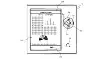
- FIG. 1 is a front view of the portable display terminal 1.
- the portable display terminal 1 has a substantially rectangular parallelepiped shape, and an electrophoretic display device 2 is provided on the front surface thereof.
- a card slot 5 in which a memory card 13 can be inserted is provided on the right side surface of the portable display terminal 1.
- the electrophoretic display device 2 is a device that performs display by electrophoresis of charged particles dispersed in a predetermined dispersion medium, and even when power supply is interrupted, This is a non-volatile display portion having a characteristic property that the display can be maintained. For this reason, even if it is a power-off state, the information maintained (held) can be visually recognized, and power saving can also be achieved.
- the electrophoretic display device 2 will be described as an example of a non-volatile display unit.
- an optical anisotropy method cholesteric liquid crystal display device, ferroelectric liquid crystal, etc.
- Display devices, particle rotation type display devices, particle movement type display devices, and the like can also be used.
- the portable display terminal 1 can display various information stored in the memory card 13 on the electrophoretic display device 2.
- information in this embodiment, at least one of characters, still images, and moving images can be displayed.
- These “information” are composed of at least one of data for displaying characters, data for displaying images, and data for displaying moving images. It can be interpreted as a document file, an image file, a moving image file, or the like to be used.
- “information” is assumed to be the above-described document file, image file, moving image file, and the like, and these “information” may be simply referred to as “file”.
- This memory card 13 is generally called an EEPROM (electrically erasable PROM, “Electrically” Erasable “Programmable” ROM), and functions as a storage unit for storing files to be displayed on the electrophoretic display device 2. .
- EEPROM electrically erasable PROM, “Electrically” Erasable “Programmable” ROM
- an operation key 3 is provided as an operation unit that can be operated by a user.
- An up key 3b, a down key 3c, a left key 3d, and a right key 3e are provided on the top, bottom, left, and right of the determination key 3a, respectively.
- the up key 3b and the down key 3c are keys for the user to select a file on the file list screen or the menu screen, or to operate buttons or the like (hereinafter simply referred to as icons) appearing on the screen.
- the left key 3d and the right key 3e are used to turn the displayed file.
- the portable display terminal 1 is provided with a rechargeable battery 6, and the portable display terminal 1 is configured to operate when power is supplied by the battery 6.
- a power button 3f is provided as the operation key 3, and the user can instruct to turn on / off the power by pressing the power button 3f.
- a “power on” instruction is issued, power is supplied to the CPU 10 and peripheral devices, and the portable display terminal 1 is in operation.
- a “power off” instruction is issued, a process for turning off the power is performed, and the power supply to the CPU 10 and peripheral devices is cut off.
- the portable display terminal 1 is not being used, and a process for turning off the power is performed. And power supply to peripheral devices is cut off.
- the portable display terminal 1 of this embodiment designates one or more files among the files stored in the memory card 13 in advance by the operation key 3 described above, so that the voltage of the battery 6 becomes a predetermined threshold value.
- the display of the electrophoretic display device 2 is rewritten with a designated file (hereinafter referred to as a designated file).
- the “power off state” in the present embodiment is a specific state such as pressing of the power button 3f or no operation for a predetermined time even when the power from the battery 6 can be supplied to the portable display terminal 1. It is in a state in which power cannot be supplied to at least one of the electrophoretic display device 2, the CPU 10, peripheral devices (RAM 12, controllers such as the display controller 14), etc. by the operation.
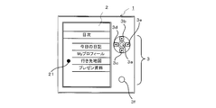
- FIG. 2 shows a selection screen for a designated file.
- FIG. 2 shows a state where “destination map” is designated as the designated file.
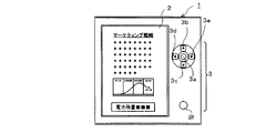
- FIG. 3A shows a fully charged state immediately after the start of use
- FIG. 3B shows a state where the remaining battery level is slightly reduced compared to the state of FIG. 3A
- FIG. 3C shows the state of FIG. 3B. Compared to this, the remaining battery level is further reduced.
- 3A to 3C the remaining amount of the battery 6 is shown at the bottom of the electrophoretic display device 2.
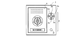
- FIG. 3C when the remaining battery level becomes small, the image displayed on the electrophoretic display device 2 when the voltage of the battery 6 becomes a predetermined threshold or less is shown in FIG. 3D.
- FIG. 2 the image is rewritten to the image by the designated file designated in the explanation of FIG.
- rewriting to information based on a specified file instead of the image that the user was browsing may be expressed as “transition”.
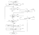
- the portable display terminal 1 performs processing as shown in FIG. Note that the flow shown in FIG. 4 is for easily understanding the operation of the portable display terminal 1 according to the present embodiment, and a more detailed flow will be described later.
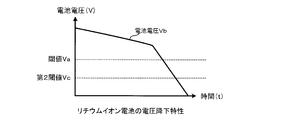
- a predetermined threshold value Va is set, and it is determined whether or not the voltage Vb supplied from the battery 6 is equal to or lower than the threshold value Va. Yes.
- step S1 determines that the voltage Vb is not equal to or lower than the threshold value Va (step S1: No).
- step S1 determines that the voltage Vb is equal to or lower than the threshold value Va (step S1: Yes).
- step S2 the control unit performs an operation of displaying the designated file on the electrophoretic display device 2.
- step S3 the portable display terminal 1 shifts the portable display terminal 1 to a power-off state in order to preserve the remaining battery level. Note that the processing in step S3 may not be executed according to user settings.
- a second threshold value Vc lower than the threshold value Va is set in advance, and when the battery voltage Vb becomes equal to or lower than the threshold value Va, the designated file is displayed but the power supply is displayed. Instead of shifting to the off state, the battery may be shifted to the power off state when the battery voltage Vb becomes equal to or lower than the second threshold value Vc.
- processing timings of steps S2 and S3 can be set according to user settings.
- the electrophoretic display device 2 can be rewritten with a designated file and set to shift to a power-off state.
- an instruction may be requested to the user as to whether or not the display of the electrophoretic display device 2 is rewritten with a specified file.
- the display of the electrophoretic display device 2 is rewritten with the designated file and then the power is turned off.
- the electrophoretic display device In the state where the current display of 2 is maintained, the portable display terminal 1 is shifted to the power-off state.
- the power supply can be shifted to the off state while taking into account the user's wish regarding whether or not rewriting with the designated file is executed.
- the user can adopt an arbitrary file as the designated file.
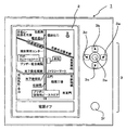
- the “destination map” shown in FIG. 3D for example, the user profile shown in FIG. 6A or the belonging of the portable display terminal 1 Information, a serial number of the portable display terminal 1 and the like may be indicated.
- the priority order of each designated file may be determined by the user and displayed on the electrophoretic display device 2 in the priority order.
- the display of the electrophoretic display device 2 is rewritten to a designated file having the highest priority among a plurality of designated files, and the portable display terminal 1 is turned on. If the voltage Vb of the battery 6 is equal to or lower than the predetermined threshold value Va when the power button 3f is operated after the transition to the off state, the display of the electrophoretic display device 2 has the next highest priority among the plurality of designated files. You may make it rewrite to a high specification file.
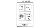
- any one of the plurality of designated files may be selected and displayed on the electrophoretic display device 2, and FIG. 7A and FIG. As shown in 7B, the display area of the electrophoretic display device 2 may be divided according to the number of designated files, and each designated file may be displayed in each divided area.
- the number of divisions may be appropriately determined by the user. For example, as shown in FIG. 7A, two designated files are displayed simultaneously in two divisions on the display area, or as shown in FIG. 7B. Alternatively, four designated files may be displayed simultaneously in four divisions.
- step S3 when charging the battery 6 is started after the designated file is displayed and the power is turned off, the page displayed when the power is turned on again displays the designated file. You may make it display the file which the user browsed before doing.
- the file displayed immediately before rewriting to the specified file or information for identifying the file (for example, the file name and the hierarchical structure of the folder storing the file) is stored, and the electrophoretic display device 2
- the display of the electrophoretic display device 2 is rewritten based on the stored file or information for identifying the file when charging of the battery is started after the display is rewritten to the designated file and the battery is charged.
- the specified file or information for identifying the file for example, the file name and the hierarchical structure of the folder storing the file
- the page displayed on the electrophoretic display device 2 is the last page displayed by the user on the electrophoretic display device 2, that is, the user among a plurality of pages. May adopt the page most recently viewed.
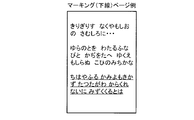
- marking information such as an underline can be added to the page displayed on the electrophoretic display device 2 as shown in FIG. 6B.
- the marking information is added to the pages. You may make it adopt the page which did.
- the portable display terminal 1 As described above, the portable display terminal 1 according to the present embodiment has such a characteristic function.
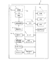
- FIG. 8 is a schematic diagram showing the electrical configuration of the portable display terminal 1
- FIGS. 9 to 11 are explanatory diagrams showing the structure of the electrophoretic display device 2.
- FIG. 8 is a schematic diagram showing the electrical configuration of the portable display terminal 1
- FIGS. 9 to 11 are explanatory diagrams showing the structure of the electrophoretic display device 2.
- FIG. 8 is a schematic diagram showing the electrical configuration of the portable display terminal 1
- FIGS. 9 to 11 are explanatory diagrams showing the structure of the electrophoretic display device 2.
- the portable display terminal 1 includes a control unit 22 that performs main control of the device itself, and a power supply unit 25 that supplies power to the entire device.
- the control unit 22 includes a CPU 10, a ROM 11, a RAM 12, an RTC 26, and an EEPROM 23.
- the ROM 11, the RAM 12, the RTC 26, and the EEPROM 23 are connected to the CPU 10, respectively.
- the CPU 10 controls the portable display terminal 1, and in particular, drives the electrophoretic display device 2 (non-volatile display unit) to display the contents according to the data constituting the file.
- the ROM 11 stores a display terminal program for operating the portable display terminal 1, and the CPU 10 functions as the control unit described above by reading this program from the ROM 11 and executing it. Specifically, a program for executing the flowcharts shown in FIGS. 12 to 23 is stored.
- the program may not be stored in the ROM 11 in advance, but may be extracted from a recording medium such as the memory card 13 via the memory card I / F 16 and stored in the ROM 11.
- a program is stored in the memory card 13 and a flash memory or the like is used as the ROM 11.
- the RAM 12 functions as a memory that temporarily stores various data and flag values used in programs executed by the CPU 10. Examples of the flag stored in the RAM 12 include a voltage state flag indicating the current voltage state of the battery 6, a charge flag indicating whether or not the battery 6 is being charged, and a process to be executed by the CPU 10. And a key input flag for temporarily storing an input from the operation key 3. The actual handling of these voltage state flag, charge flag, task flag, and key input flag in the program will be described later in detail with reference to the flowcharts shown in FIGS.
- the RTC (Real Time Clock) 26 is used to generate a clock pulse that serves as a reference for executing a system timer interrupt process described later. Even in a state where the main process is being executed, the CPU 10 interrupts the main process in accordance with a clock pulse generated every predetermined period (for example, 2 milliseconds) from the RTC 26, and performs a system timer interrupt process. May be executed.
- the EEPROM 23 is a non-volatile memory for storing information such as affiliation information, serial number, and user information of the portable display terminal 1 even if the power supply to the portable display terminal 1 is cut off. is there.
- the EEPROM 23 also functions as a memory that temporarily stores flag values and the like used in programs executed by the CPU 10.
- a flag stored in the EEPROM 23 for example, a display area division number flag indicating the number of divisions of a display area when displaying a designated file, or a cause when the portable display terminal 1 shifts to a power-off state is shown. Examples include a system termination cause flag, a transition necessity flag indicating whether or not a specified file needs to be displayed, and a transition display count flag indicating the number of times a specified file has been displayed.
- the actual handling of these display area division number flag, system end cause flag, transition necessity flag, and transition display number flag in the program will be described later in detail with reference to the flowcharts shown in FIGS. .
- the power supply unit 25 includes a rechargeable battery 6, a charging unit 7 that controls power storage in the battery 6, a power supply control unit 24 that controls power supply to the control unit 22 and the entire device, and the portable display terminal 1.
- a power button 3f for turning the power on and off is provided.
- Reference numeral 8 denotes a terminal for inserting a cable connecting the household outlet and the charging unit 7.
- the battery 6 is a storage battery that can be repeatedly charged and discharged, and functions as an internal power source of the portable display terminal 1 by storing power in the battery 6 in advance when the portable display terminal 1 is used. It is.
- the charging unit 7 controls the charging voltage to the battery 6 and plays a role of supplying power supplied from a household outlet to the battery 6 according to the remaining battery capacity and characteristics of the battery 6. .
- the power supply control unit 24 controls power supply to the entire portable display terminal 1. Further, it has a function of monitoring the voltage value of the battery 6 and transmitting the value to the control unit 22 (CPU 10 described later). Note that the power supply control unit 24 monitors whether or not a power button 3f described below is operated even when the portable display terminal 1 is turned off.
- the power button 3f is a push-type switch connected to the power supply control unit 24. When pressed, the power button 3f transmits a signal to the power supply control unit 24, and the power supply control unit 24 is based on this signal. 1 is turned on or off.
- this portable display terminal 1 it is possible to instruct power on / off by pressing the power button 3f.
- a “power on” instruction is issued, power is supplied to the CPU 10 and peripheral devices, and the portable display terminal 1 is in an operating state.
- a “power off” instruction is issued, a process for turning off the power is performed, and power supply to the CPU 10 and peripheral devices is cut off.
- control unit 22 is connected with a key I / F 15, a display controller 14, a touch panel 9, and a memory card I / F 16.
- the operation key 3 is connected to the key I / F 15 and has a function of processing signals input from the enter key 3a, the up key 3b, the down key 3c, the left key 3d, and the right key 3e and transmitting them to the CPU 10. Have.
- the display controller 14 is connected to the electrophoretic display device 2 (see FIG. 1), and controls display of images on the electrophoretic display device 2.
- the touch panel 9 is disposed in a state of being stacked on the upper layer of the electrophoretic display device 2, and the user can select items displayed on the electrophoretic display device 2 by touching with a stylus or a touch pen, It functions as a marking adding unit for marking the display image.
- the memory card I / F 16 is disposed inside the card slot 5 and controls reading and writing of files from the memory card 13.
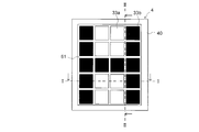
- FIG. 9 is a front view of the electrophoretic display device 2.
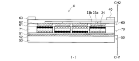
- 10 is a cross-sectional view taken along line II (FIG. 9) of the electrophoretic display device 2
- FIG. 11 is a cross-sectional view taken along line II-II (FIG. 9) of the electrophoretic display device 2.
- FIG. 9 is a front view of the electrophoretic display device 2.
- 10 is a cross-sectional view taken along line II (FIG. 9) of the electrophoretic display device 2
- FIG. 11 is a cross-sectional view taken along line II-II (FIG. 9) of the electrophoretic display device 2.
- FIG. 9 is a front view of the electrophoretic display device 2.
- 10 is a cross-sectional view taken along line II (FIG. 9) of the electrophoretic display device 2
- FIG. 11 is a cross-sectional view taken along line II-II (FIG. 9) of the electrophoretic display device 2.
- the electrophoretic display device 2 includes a lower substrate 50 provided on a lower surface portion thereof and an upper substrate 60 provided on an upper surface portion thereof so as to be opposed to each other.
- a display unit 70 is provided between the two.
- the II line indicates a line parallel to the horizontal direction (left and right direction in FIG. 1) of the portable display terminal 1
- the II-II line indicates a line parallel to the vertical direction (vertical direction in FIG. 1).
- the number of pixels is 20 (5 ⁇ 4) for ease of explanation, but in practice, the number of pixels can be provided as necessary.
- the lower substrate 50 includes a lower electrode 52 that generates an electric field in the display unit 70, a lower electrode protective film 51 that is an insulating film formed by applying an insulating material on the upper surface side of the lower electrode 52, and a lower surface of the lower electrode 52. And a housing support portion 53 that is provided on the side and supports the portable display terminal 1.
- the lower electrode protective film 51 is formed of a material capable of exhibiting high insulation properties such as a resin film such as polyethylene terephthalate or silica, or an inorganic material such as glass.
- the lower electrode protective film 51 and the housing support portion 53 are plastic substrates (resin films) made of flexible polyethylene terephthalate.
- the lower electrode 52 is a substrate having a plurality of electrodes in which linear electric conductors are arranged in parallel in the horizontal direction (II line direction) so that a constant voltage is applied.
- the upper substrate 60 is provided above the lower substrate 50 so as to be opposed to the lower substrate 50 and in parallel with a predetermined interval.
- the upper substrate 60 includes an upper electrode 62 that generates an electric field in the display unit 70, an upper electrode protective film 61 that is an insulating film formed by applying an insulating material on the lower surface side of the upper electrode 62, and an upper surface of the upper electrode 62.
- a display layer 63 that is provided on the side and is configured by a transparent member and functions as a display screen.
- the upper electrode protective film 61 is formed of a material that can exhibit high transparency, such as polyimide, polyethylene terephthalate, or glass.
- the upper electrode 62 is a substrate having a plurality of electrodes in which linear electric conductors are arranged in parallel in the vertical direction (II-II line direction) so that a constant voltage is applied, It is made of a material that can exhibit high transparency.
- the upper electrode protective film 61 is a plastic substrate (resin film) made of polyethylene terephthalate.
- the upper electrode 62 is a transparent electrode formed of indium tin oxide (ITO), and the display layer 63 is a glass substrate. That is, since the upper substrate 60 is a transparent body, it functions as a display substrate that allows the user to visually recognize the display unit 70 from above the upper substrate 60.
- a gap formed by the lower substrate 50 and the upper substrate 60 that are provided to face each other and the spacer 71 is the display unit 70.
- the spacer 71 is installed in a gap between the lower substrate 50 and the upper substrate 60, and the gap is equally divided into a lattice to form a plurality of small compartment cells, and supports the lower substrate 50 and the upper substrate 60.
- the spacer 71 is a flexible member configured as a plate-like member in which a plurality of through holes are formed in a lattice shape, and may be formed of a synthetic resin such as polyimide or polyethylene terephthalate.
- the display unit 70 is filled with charged particles 33a and 33b and a dispersion medium 34.
- the charged particles 33a and 33b are made of a material that can be charged in the dispersion medium 34, and are made of a pigment or dye made of an organic compound or an inorganic compound, or a pigment or dye wrapped with a synthetic resin.
- the charged particles 33a are a mixture of styrene resin and titanium dioxide, and have an average particle diameter of 5 ⁇ m (7 wt%), and the amount of titanium dioxide in the particles is 40 wt%.
- the charged particles 33b are a mixture of styrene resin and carbon black and have an average particle size of 5 ⁇ m (10 wt%), and the amount of carbon black in the particles is 30 wt%. Therefore, the charged particles 33a have a white color tone, and the charged particles 33b have a black color tone.
- the charged particles 33a and the charged particles 33b are charged so as to be different from each other positively or negatively. Here, it is assumed that the charged particles 33a are negatively charged and the charged particles 33b are positively charged.
- the dispersion medium 34 alcohols, hydrocarbons, silicone oil, etc. that can exhibit high insulation properties and have low viscosity can be used.
- Isopar 73 wt%) manufactured by ExxonMobil, which is a paraffinic solvent, is used.
- ethanol (10 wt%) is added to the dispersion medium 34 as an additive.
- the mask part 40 is a square-shaped plate-like member provided with a constant width along the four sides of the upper substrate 60 and provided with a through-hole so that the user can visually recognize the display part 70.
- Polyethylene terephthalate What is necessary is just to attach what colored synthetic resins, such as these, or to form with the ink layer printed on the surface of the display layer 63.
- FIG. When the electrophoretic display device 2 is viewed from above, the display unit 70 can be viewed from the through hole provided in the mask unit 40.
- FIG. 12 is a flowchart showing the operation of the main process executed in the portable display terminal 1
- FIG. 13 is a flowchart showing the operation of the system timer interrupt process
- FIGS. 14 to 17 are the main process of FIG.
- FIG. 18 to FIG. 23 are flowcharts showing the operation of the sub-process branching from the system timer interrupt process of FIG. 13.
- the display state on the electrophoretic display device 2 displayed according to the flowcharts of FIGS. 12 to 23 will be described with reference to FIGS. 24 to 27.
- each flag referred to by the CPU 10 during processing will be described.
- the flags used in the present embodiment are roughly divided into three flags: a flag stored in the RAM 12, a flag stored in the EEPROM 23, and a flag set in each file itself.
- the voltage state flag stored in the RAM 12 and indicating the state of the current voltage Vb of the battery 6 is a flag that takes values from “0” to “2”, and is “0: greater than the threshold Va”, “1: threshold Va. "," Means "2: below the second threshold value Vc".
- the charging flag stored in the RAM 12 and indicating whether or not the battery 6 is being charged is a flag having a value of “0” or “1”, and “0: not charging”, “1: charging” Is.
- a task flag stored in the RAM 12 and indicating a process to be executed by the CPU 10 is a flag having a value of “1” to “4”, and is “1: menu screen display process”, “2: file designation process”, “ 3: File list display processing ”,“ 4: File display processing ”.
- the display area division number flag stored in the EEPROM 23 and indicating the division number of the display area when the designated file is displayed takes a value of “1” or more (for example, 1 to 4).
- the system termination cause flag stored in the EEPROM 23 and indicating the cause when the portable display terminal 1 shifts to the power-off state is a flag having a value of “1” or “2”, “1: normal termination”, “2: Termination due to voltage drop”.
- the transition necessity flag stored in the EEPROM 23 and indicating whether or not the specified file is displayed is a flag having a value of “0” or “1”, and “0: transition display is necessary”, “1: transition”. It means “no need to display”.
- the transition display count flag stored in the EEPROM 23 and indicating the number of times the specified file has been displayed is a flag having a value of “0” or “1” or more, “0: The specified file is not displayed”, “ A value of “1” or more indicates the number of times the specified file has been displayed.
- the designated file flag that is set in each file itself and indicates that the file is designated by the user is a flag that takes a value of “0” or “1”, “0: not a designated file”, “1: It is a specified file.
- the priority flag set in each file itself and indicating the priority order of the designated file displayed on the electrophoretic display device 2 takes a value of “1” or more, and the smaller the value, the higher the priority.
- the memory card that stores the file having the priority flag functions as a priority storage unit that stores the priority.
- the viewing flag that is set for each file and indicates that the file is currently being browsed by the user is a flag that takes a value of “0” or “1”, and is “0: not viewed”, “1”. : “Browsing”.
- a final browsing page flag set in each file itself and indicating the number of pages viewed last by the user in the file is a flag having a value of “1” or more, and the value is the last page viewed. Shows the number.
- the marking flag that is set in each file itself and indicates whether or not the user has marked the file is a flag that takes a value of “0” or “1”, “0: no marking”, “1: marking is present” "Means.
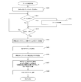
- the CPU 10 executes the following processing.
- the CPU 10 of the control unit 22 of the portable display terminal 1 first executes an initial setting process such as RAM access permission and work area initialization (step S10). At this time, a task flag, a voltage state flag, and a charge flag are set in the RAM 12. Note that the values of the task flag, the voltage state flag, and the charge flag are written at any time according to the operating state of the portable display terminal 1 by an interrupt process described later.
- an initial setting process such as RAM access permission and work area initialization
- the CPU 10 reads the value of the task flag from the RAM 12 (step S11), and determines whether or not the value of the task flag is “1: menu screen display process” (step S12).
- step S12 Yes
- the menu screen display process is executed (step S13).
- the menu screen display process will be described later with reference to FIG.
- step S12 determines that the value of the task flag is not “1: menu screen display process” (step S12: No). the process proceeds to step S14.
- the CPU 10 determines whether or not the value of the task flag is “2: file designation process” (step S14).
- step S14 the file designation process is executed (step S15). This file designation process will be described later with reference to FIG.
- step S14 No
- the process proceeds to step S16.
- the CPU 10 determines whether or not the value of the task flag is “3: file list display process” (step S16).
- step S16 Yes
- the file list display process is executed (step S17).
- the file list display process will be described later with reference to FIG.
- step S16 determines that the value of the task flag is not “3: file list display process” (step S16: No), the process proceeds to step S18.
- the CPU 10 determines whether or not the value of the task flag is “4: file display process” (step S18).
- step S18 Yes
- step S19 This file display process will be described later with reference to FIG.
- step S18: No the process moves to step S11 again and is repeatedly executed.
- the CPU 10 may interrupt the main process and execute the system timer interrupt process even when the main process is being executed.
- the following system timer interrupt processing is executed in response to a clock pulse generated every predetermined period (for example, 2 milliseconds) from the RTC 26.
- step S20 the CPU 10 executes a power button pressing process for turning off the portable display terminal 1 (step S20). The process when the power button is pressed will be described in detail later with reference to FIG.
- the CPU 10 executes a process when the operation key is pressed to accept an input from the operation key 3 such as the enter key 3a, the upper key 3b, the lower key 3c, the left key 3d, and the right key 3e (step S21).
- a key input flag is written to a predetermined address of the RAM 12 as to which key has been input. This key input flag is used for determining whether or not there is a key input by referring to it in another processing step.
- the CPU 10 executes a touch-panel contact process for receiving input from the touch panel 9 disposed on the electrophoretic display device 2 (step S22).
- This touch panel touch processing will be described later in detail with reference to FIG.
- step S23 the CPU 10 executes a battery voltage confirmation process for checking the voltage of the battery 6 (step S23). This battery voltage confirmation process will be described later in detail with reference to FIG.
- the CPU 10 executes a special system startup process for changing the display content of the electrophoretic display device 2 at startup according to the cause of the previous system termination (step S24). This special process at system startup will be described later in detail with reference to FIG.
- the CPU 10 executes a system end confirmation process for determining whether or not to display the designated file and whether or not to turn off the portable display terminal 1 (step S25).
- This system termination confirmation process will be described in detail later with reference to FIG.
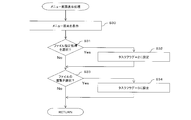
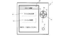
- the CPU 10 also displays a file designation process icon 81 for instructing the electrophoretic display device 2 to shift to the file designation process and a file browsing for instructing the file list display process to shift.
- a menu screen 80 having icons 82 is displayed (step S30).
- the CPU 10 determines whether or not the file designation processing icon 81 has been selected by the user (step S31).
- step S31 if the CPU 10 determines that the file designation process icon 81 has been selected (step S31: Yes), the process proceeds to step S32.
- step S32 the value of the task flag stored at a predetermined address in the RAM 12 is set to “2: file designation process”, and the process proceeds to step S33.
- step S31 determines in step S31 that the file designation process icon 81 has not been selected (step S31: No), the process proceeds to step S33.
- the CPU 10 determines whether or not the file browsing icon 82 has been selected by the user (step S33).
- step S33 if the CPU 10 determines that the file browsing icon 82 has been selected (step S33: Yes), the process proceeds to step S34.
- step S34 the value of the task flag stored in the predetermined address of the RAM 12 is set to “3: file list display process”, and the process is returned to the address before branching.
- step S33 determines in step S33 that the file browsing icon 82 has not been selected (step S33: No)
- the process returns to the address before branching.
- step S15 of the main process shown in FIG. 12 will be described with reference to FIGS.
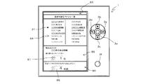
- the CPU 10 first displays a file designation screen 83 as shown in FIG. 25, and displays a list 84 of files that can be designated (step S40).
- the CPU 10 refers to a key input flag stored at a predetermined address in the RAM 12 and determines whether or not there is a key input from the up key 3b, the down key 3c, the left key 3d, and the right key 3e (step). S41).
- step S41 determines that there is a key input
- step S42 the cursor 21 on the file designation screen 83 is moved (step S42), and the process proceeds to step S43.
- step S41 determines in step S41 that there is no key input (step S41: No)
- the process proceeds to step S43.
- the CPU 10 selects any file from the list 84 of files that can be specified by the user, and determines whether or not the enter key 3a is pressed.
- step S43 if the CPU 10 determines that the enter key 3a has been pressed (step S43: Yes), the process proceeds to step S44.
- step S43 determines that the enter key 3a has not been pressed (step S43: No)
- the process proceeds to step S41 again.
- the CPU 10 designates the selected file as a designated file, and sets a value of “1: designated file” as a designated file flag in the file (step S44).
- the determination key 3a and the control unit 22 (CPU 10) that executes Steps S43 to S44 cooperate to function as an information specifying unit.
- the CPU 10 requests the user to input the priority order of the designated file on the priority order input screen 85 (step S45).
- the CPU 10 sets a priority order flag for the designated file, and sets the value of the priority order flag as the inputted priority order value (Ste S46).
- the CPU 10 requests input of the number of divisions of the display area when displaying the designated file on the division display setting screen 86 (step S47).
- the input value is stored in the EEPROM 23 as the value of the display area division number flag.
- the CPU 10 sets the value of the task flag stored at a predetermined address in the RAM 12 to “1: menu screen display process” (step S48), and returns the process to the address before branching.
- the CPU 10 displays a file list screen 90 as shown in FIG. 26, and displays a list 91 of files that can be browsed (step S50).
- the CPU 10 refers to the key input flag stored at a predetermined address in the RAM 12 and determines whether or not there is a key input from the upper key 3b, the lower key 3c, the left key 3d, and the right key 3e (Ste S51).
- step S51 when the CPU 10 determines that there is a key input (step S51: Yes), the cursor 21 on the file list screen 90 is moved (step S52), and the process proceeds to step S53.
- step S51 determines in step S51 that there is no key input (step S51: No)
- step S53 the process proceeds to step S53.
- the CPU 10 determines whether or not the icon 92 for returning to the menu screen on the file list screen 90 is selected and the enter key 3a is pressed (step S53).
- step S53: Yes When the CPU 10 determines that the icon 92 for returning to the menu screen is selected and the enter key 3a is pressed (step S53: Yes), the CPU 10 sets the value of the task flag stored in the predetermined address of the RAM 12 to “1: menu. "Screen display process" is set (step S54), and the process returns to the address before branching.
- step S53 determines that the icon 92 for returning to the menu screen is selected and the determination key 3a is not pressed.
- step S55 the CPU 10 determines whether or not a predetermined file has been selected and the enter key 3a has been pressed.
- step S55 If the CPU 10 determines that a predetermined file has been selected (step S55: Yes), the process proceeds to step S56.
- step S55: No the process proceeds to step S51 again.
- the CPU 10 sets “1: browsing” as the value of the browsing flag in the selected file (step S56), and sets the value of the task flag stored at a predetermined address in the RAM 12 to “4: file display processing”. After setting (step S57), the process returns to the address before branching.
- step S19 of the main process shown in FIG. 12 will be described with reference to FIGS.
- the CPU 10 displays a file display screen 93, reads out a file with the viewing flag set to 1 from the files stored in the memory card 13, An information image 94 is displayed (step S60).
- the CPU 10 refers to a key input flag stored at a predetermined address in the RAM 12 and determines whether or not there is a key input from the upper key 3b, the lower key 3c, the left key 3d, and the right key 3e (Ste S61).
- step S61 If the CPU 10 determines that a key input has been made (step S61: Yes), the CPU 21 moves the cursor 21 on the file display screen 93, or if the file being viewed extends over a plurality of pages. A page turning process is executed (step S62), and the process proceeds to step S63.
- step S61 determines in step S61 that there is no key input (step S61: No)
- step S63 proceeds to step S63.
- the CPU 10 determines whether or not the browse end icon 95 on the file display screen 93 is selected and the determination key 3a is pressed (step S63).
- step S63 Yes
- the process returns to step S64.
- step S63 No
- the process proceeds to step S61 again.
- the CPU 10 sets the value of the browsing flag recorded in the file being browsed to “0: not browsing” (step S64).
- the CPU 10 determines whether or not the file being browsed is a file extending over a plurality of pages (step S65).
- step S65 when the CPU 10 determines that the file being browsed is a file extending over a plurality of pages (step S65: Yes), the process proceeds to step S66.
- step S66 the value of the page browsed last by the user among the browsed files is recorded in the file as the value of the last browsed page flag. For example, when the file browsed by the user is a file covering all 10 pages and the last page browsed by the user is the eighth page, the file has “8” as the value of the final browse page flag. Is recorded.
- the CPU 10 moves the process to step S68.
- step S65 determines in step S65 that the file being browsed is not a file extending over a plurality of pages (step S65: No), the process proceeds to step S67.
- step S67 “1” is recorded as the value of the last browsing page flag in the file that was being browsed.
- the CPU 10 sets the value of the task flag stored at a predetermined address in the RAM 12 to “3: file list display process” (step S68), and returns the process to the address before branching.
- step S20 of the system timer interrupt process shown in FIG. 13 will be described with reference to FIG.
- the CPU 10 first determines whether or not the power button 3f has been pressed (step S70).
- step S70 if the CPU 10 determines that the power button 3f has not been pressed (step S70: No), the process is returned to the address before branching.
- step S70 determines that the power button 3f has been pressed.
- the CPU 10 displays on the electrophoretic display device 2 that the system termination process is being performed (step S71).
- the display at this time can be, for example, a display such as “Power is turned off because the power button is pressed”.
- the CPU 10 rewrites the value of the system termination cause flag stored in the EEPROM 23 to a value of “1: normal termination”, and instructs the power supply control unit 24 to stop supplying power to other than the power supply unit 25. Then, the portable display terminal 1 is turned off (step S72).
- step S22 of the system timer interrupt process shown in FIG. 13 will be described with reference to FIG.
- the CPU 10 determines whether or not the touch panel 9 disposed on the electrophoretic display device 2 has been touched (step S80).
- step S80: No the process is returned to the address before branching.
- step S80 determines that the touch panel 9 has been touched.
- the CPU 10 determines whether or not the value of the task flag stored in the predetermined area of the RAM 12 is “4: file display process”, that is, whether or not the file display process in step S19 is being executed. Is performed (step S81).
- step S81: No the process is returned to the address before branching.
- step S81: Yes the process proceeds to step S82.
- the CPU 10 confirms the coordinates on the touch panel 9 touched, and displays the handwriting on the electrophoretic display device 2 (step S82).
- step S83 the file being displayed on the electrophoretic display device 2 is rewritten by overwriting the displayed handwriting data (step S83), and the marking flag recorded in the file is set to “1: with marking” (step S83).
- step S84 the process is returned to the address before branching.
- step S23 of the system timer interrupt process shown in FIG. 13 will be described with reference to FIG.
- the CPU 10 sets the value of the voltage state flag stored at a predetermined address in the RAM 12 to “0: greater than the threshold value Va” (step S90).
- the CPU 10 requests the power supply control unit 24 for the value of the voltage Vb of the battery 6 and acquires the value of the voltage Vb of the battery 6 (step S91).
- the CPU 10 determines whether or not the acquired value of the voltage Vb is equal to or less than the threshold value Va (step S92).
- step S92 determines that the acquired value of the voltage Vb is equal to or less than the threshold value Va (step S92: Yes)
- the value of the voltage state flag stored in the predetermined address of the RAM 12 is set to “1: threshold value”. "Va or less” is set (step S93), and the process proceeds to step S94.
- step S92 determines that the acquired value of the voltage Vb is not less than or equal to the threshold value Va (step S92: No), the process proceeds to step S94.
- the CPU 10 determines whether or not the acquired value of the voltage Vb is equal to or less than the second threshold value Vc (step S94).
- step S94 If the CPU 10 determines that the acquired voltage Vb value is equal to or lower than the second threshold value Vc (step S94: Yes), the value of the voltage state flag stored at a predetermined address in the RAM 12 is set to “2”. : Second threshold Vc or less ”(step S95), and the process proceeds to step S96.
- step S94 determines that the acquired value of the voltage Vb is not less than or equal to the second threshold value Vc (step S94: No). the process proceeds to step S96.
- the CPU 10 checks the power supply control unit 24 as to whether or not charging is in progress (step S96), and determines whether or not charging is in progress (step S97).
- step S97 If the CPU 10 determines that charging is in progress (step S97: Yes), the value of the charging flag stored at a predetermined address in the RAM 12 is set to “1: charging” (step S98). Return processing to the address before branching.
- step S97 the value of the charging flag stored at a predetermined address in the RAM 12 is set to “0: not charging” (step S99). ) Return the processing to the address before branching.
- step S24 of the system timer interrupt process shown in FIG. 13 will be described with reference to FIG.
- the CPU 10 refers to the value of the system termination cause flag stored in a predetermined address of the EEPROM 23 (step S100).
- the CPU 10 determines whether or not the value of the referred system termination cause flag is “2: termination due to voltage drop” (step S101).
- step S101: No the process is returned to the address before branching.
- step S101: Yes the process proceeds to step S102.
- the CPU 10 refers to a predetermined address in the RAM 12 and determines whether or not the value of the voltage state flag is “0: greater than the threshold value Va” (step S102).
- step S102 determines that the value of the voltage state flag is not “0: greater than the threshold value Va” (step S102: No), the process proceeds to step S103.
- step S103 the CPU 10 refers to a predetermined address in the RAM 12 and determines whether or not the value of the charge flag is “1: charging”.
- step S105 If the CPU 10 determines that the value of the charging flag is “1: charging”, the process proceeds to step S105, and if the value of the charging flag is not “1: charging”. Sets the value of the transition necessity flag stored at the predetermined address of the EEPROM 23 to “0: Necessity of transition display” (step S104), and returns the processing to the address before branching.
- step S102 determines in step S102 that the value of the voltage state flag is “0: greater than the threshold value Va” (step S102: Yes)
- the process proceeds to step S105.
- the CPU 10 refers to a predetermined address in the EEPROM 23 and determines whether or not the user has set in advance to display a file browsed by the user immediately before displaying the designated file (hereinafter referred to as a file immediately before transition). A determination is made (step S105).
- step S105 determines that the setting is set to display the file immediately before the transition.
- step S105 determines that it is not set to display the file immediately before the transition.
- step S106 the file immediately before the transition is read from the EEPROM 23, and the value of the browsing flag of the file is set to “1: browsing”.
- step S107 the CPU 10 sets the value of the task flag stored at a predetermined address of the RAM 12 to “4: file display process” (step S107), and moves the process to step S108.
- step S108 the CPU 10 sets the value of the system termination cause flag stored in the predetermined address of the EEPROM 23 to “1: normal termination”.
- the CPU 10 sets the value of the transition necessity flag stored at the predetermined address of the EEPROM 23 to “0: Necessity of transition display” (step S109), and further displays the transition display stored at the predetermined address of the EEPROM 23.
- the value of the number flag is set to “0: not displayed” (step S110), and the process is returned to the address before branching.
- step S25 of the system timer interrupt process shown in FIG. 13 will be described with reference to FIG.
- the CPU 10 refers to the value of the voltage state flag stored at a predetermined address in the RAM 12 (step S120).
- the CPU 10 determines whether or not the value of the referenced voltage state flag is “2: the second threshold value Vc or less” (step S121).
- step S121 Yes
- the process proceeds to step S127.
- step S121: No the process proceeds to step S122.
- step S122 the CPU 10 determines whether or not the value of the referenced voltage state flag is “1: threshold value Va or less”.
- step S122: No the process is returned to the address before branching.
- step S122: Yes the process proceeds to step S123.
- the CPU 10 refers to the value of the transition necessity flag stored in the predetermined address of the EEPROM 23, and determines whether or not the value is “0: necessity of transition display” (step S123).
- step S123: No the process is returned to the address before branching.
- step S123: Yes the process proceeds to step S124.
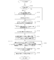
- step S124 the CPU 10 executes a page transition process for displaying the designated file designated in advance in the file designation process (step S15) instead of the screen display by the file being browsed.
- This page transition process will be described later in detail with reference to FIG.
- the CPU 10 shifts the process to step S125.
- step S125 the CPU 10 determines in advance whether or not the user has set the portable display terminal 1 to the off state after displaying the designated file.
- step S125 Yes If the CPU 10 determines that the setting is for shifting to the off state (step S125: Yes), the process proceeds to step S127.
- step S125 determines that the setting is not to shift to the off state
- step S125: No the value of the transition necessity flag stored in the predetermined address of the EEPROM 23 is set to “1: transition display not required”.
- Step S126 the process is returned to the address before branching.
- step S127 the CPU 10 displays on the electrophoretic display device 2 that the system is being terminated.
- This display may be, for example, a display that informs the user that the portable display terminal 1 has been turned off due to a decrease in the voltage of the battery 6, such as “The battery has dropped and the power has been turned off.” It ’s fine.
- the CPU 10 sets the value of the system termination cause flag stored in the predetermined address of the EEPROM 23 to “2: termination due to voltage drop”, and stops supplying power to the power supply control unit 24 other than the power supply unit 25.
- the portable display terminal 1 is turned off by instructing to do so (step S128).
- step S124 of the system termination confirmation process shown in FIG. 22 will be described with reference to FIG.
- the CPU 10 refers to the value of the transition display count flag stored at a predetermined address in the EEPROM 23 and determines whether or not the value is “0: not displayed” (step S130). ).
- step S130: No the process proceeds to step S133.
- step S130: Yes the process proceeds to step S131.
- step S131 when the user is browsing an arbitrary file, the CPU 10 stores the displayed file at a predetermined address of the EEPROM 23. Note that what is stored in the EEPROM 23 is not the file being browsed but the file name or directory of the file.
- the EEPROM 23 and the CPU 10 that executes this step S131 cooperate to identify the file displayed on the electrophoretic display device 2 or the file immediately before rewriting the display on the electrophoretic display device 2 to the designated file. It functions as a second storage unit that stores information to be stored.
- the CPU 10 similarly sets the value of the transition number flag stored at the predetermined address of the EEPROM 23 to “1: 1 displayed” (step S132).
- the CPU 10 selects and reads only the file whose designated file flag value is “1: designated file” from among the files stored in the memory card 13 (step S133).
- the CPU 10 refers to the priority order flag of each read file, and sorts the priority order flag values in ascending order, that is, in descending order of priority (step S135).
- the CPU 10 refers to a predetermined address of the EEPROM 23 and acquires the value of the display area division number flag and the value of the transition display number flag set on the division display setting screen 86 in the file designation process (step S15) (step S136). ).
- the CPU 10 sets the value of the acquired display area division number flag as X and the value of the transition display number flag as Y, and selects X (Y ⁇ 1) from the files sorted in step S135. ) Files corresponding to the + 1st to XYth are extracted (step S137).
- the CPU 10 performs a process of extracting only one page from a plurality of pages, among the extracted X files, for a file extending over a plurality of pages (step S138).
- marking flag for a file that spans multiple pages is “1: Marked”, that is, if the file is a file that has been browsed by the user in the past and has also been marked, marking Extract the pages that are being used.
- the marking flag when the value of the marking flag is “0: no marking” and the value of the last viewed page flag is not “0”, that is, the file has been browsed by the user in the past, but the marking is not performed. If it is not, extract the last viewed page.
- the last browse page flag value is “0”, that is, if the file has never been browsed by the user, the first page of the file is extracted.
- the CPU 10 that has performed processing for extracting only one page from a file covering a plurality of pages displays X files and pages on the electrophoretic display device 2 (step S139). That is, when one file or page is displayed, it is displayed on the entire screen. When two or more files or pages are displayed, the display area is divided into X pieces and each file or page is electrophoresed. Display on the device 2.
- the CPU 10 adds “1” to the value of the transition display number flag stored in the predetermined address of the EEPROM 23 (step S140), and returns the process to the address before branching.
- the portable display terminal 1 operates according to the flow described above.
- the portable display terminal 1 operates using a battery as an operating power source, and maintains a display state even when power supply from the battery is cut off.
- a control unit that drives a non-volatile display unit to display information on the non-volatile display unit, a storage unit that stores information to be displayed on the non-volatile display unit, and one of the information stored in the storage unit
- An information designating unit that designates the above information, and the control unit designates information to be displayed on the non-volatile display unit when the voltage of the battery falls below a predetermined threshold. Therefore, when the voltage of the built-in battery is equal to or lower than a predetermined threshold value, information desired by the user can be displayed on the nonvolatile display unit.
Landscapes
- Engineering & Computer Science (AREA)
- Physics & Mathematics (AREA)
- Computer Hardware Design (AREA)
- General Physics & Mathematics (AREA)
- Theoretical Computer Science (AREA)
- Power Sources (AREA)
- Telephone Function (AREA)
- Electrochromic Elements, Electrophoresis, Or Variable Reflection Or Absorption Elements (AREA)
- Control Of Indicators Other Than Cathode Ray Tubes (AREA)
Abstract
内蔵した電池の電圧が所定閾値以下となった場合において、ユーザの所望とする情報を不揮発性表示部に表示することができる携帯型表示端末及びプログラムを記録した記録媒体を提供する。 電池を動作電源として動作し、前記電池からの電力供給が断たれたときでも表示状態を維持する不揮発性表示部と、前記不揮発性表示部を駆動して、前記不揮発性表示部に情報を表示する制御部と、前記不揮発性表示部に表示する情報を記憶する記憶部と、前記記憶部に記憶された情報のうち1以上の情報を指定する情報指定部と、を備え、前記制御部は、前記電池の電圧が所定閾値以下となったとき、前記不揮発性表示部に表示する情報を、前記情報指定部により指定された情報に書き換えることとした。
Description
本発明は、携帯型表示端末及びプログラムを記録した記録媒体に関するものであり、電源からの電力供給が断たれたときでも表示を維持する携帯型表示端末及びプログラムを記録した記録媒体に関するものである。
従来、電源からの電力供給が断たれたときにおいても表示状態を保持する不揮発性表示部を備えた電子ペーパー等の携帯型表示端末が使用されている(例えば、特許文献1参照)。このような携帯型表示端末では、電源オン状態から電源オフ状態となる直前において不揮発性表示部に表示されている情報をそのまま維持することによって、内蔵した電池の残量が不足して電源オン状態から電源オフ状態に移行した後においても、表示されていた情報をユーザに対して閲覧可能に表示させることができる。
一般に携帯型表示端末においては、電池の残量が少なくなったことを警告するようにしており、これによりユーザはもう少しで使用できなくなることを把握することができる(例えば、特許文献2参照)。
特開2007-187927号公報
特開平10-23309号公報
しかしながら、上記従来の携帯型表示端末では、電池の残量が少なくなったことは把握できるものの、あとどのくらいの時間で電池残量が不足することになるのかを正確に把握することができない。
従って、電池の残量が少なくなったことの警告があった後、ユーザがさらに携帯型表示端末を使用しているときに突然電源オフ状態になると、ユーザが所望しない表示が維持されてしまう場合がある。
そこで、本発明は、内蔵した電池の電圧が所定閾値以下となった場合において、ユーザの所望とする情報を不揮発性表示部に表示することができる携帯型表示端末及びプログラムを記録した記録媒体を提供することを目的とする。
上記目的を達成するために、本発明の一つの観点によれば、携帯型表示端末において、電池を動作電源として動作し、前記電池からの電力供給が断たれたときでも表示状態を維持する不揮発性表示部と、前記不揮発性表示部を駆動して、前記不揮発性表示部に情報を表示する制御部と、前記不揮発性表示部に表示する情報を記憶する記憶部と、前記記憶部に記憶された情報のうち1以上の情報を指定する情報指定部と、を備え、前記制御部は、前記電池の電圧が所定閾値以下となったとき、前記不揮発性表示部に表示する情報を、前記情報指定部により指定された情報に書き換えることとした。
このように構成することにより、電池残量が少ない場合において、指定された情報(例えば、ユーザの所望とする情報)を不揮発性表示部に表示することができ、ユーザが所望しない表示が揮発性表示部に維持されてしまう状態を防止することができる。
また、前記携帯型表示端末において、前記制御部は、前記不揮発性表示部に表示する情報を前記指定された情報に書き換えた後、自装置を電源オフ状態に移行する構成にしてもよい。
このように構成することにより、不揮発性表示部に指定された情報を表示しながらも、消費電力を可及的少なくすることができる。
また、前記携帯型表示端末において、前記情報指定部により指定された情報に対する優先度を記憶する優先度記憶部と、自装置を電源オフ状態から電源オン状態へ移行させる操作部とを備え、前記制御部は、前記指定された情報が複数あるとき、前記電池の電圧が前記所定閾値以下となると、前記不揮発性表示部に表示する情報を前記指定された複数の情報のうち優先度が最も高い情報に書き換えて自装置を電源オフ状態に移行し、その後、前記操作部が操作されたときに前記電池の電圧が前記所定閾値以下であるときには、前記不揮発性表示部に表示する情報を前記指定された複数の情報のうち優先度が次に高い情報に書き換える構成にしてもよい。
このように構成することにより、消費電力を可及的少なくしながらも、複数の指定された情報を、不揮発性表示部に優先度の高い順に表示させることができる。
また、前記携帯型表示端末において、前記制御部は、前記電池の電圧が所定閾値以下となって前記不揮発性表示部に表示する情報を前記情報指定部により指定された情報に書き換えた後、前記電池の電圧が前記所定閾値よりも低い第2閾値以下となったときに電源オフ状態に移行する構成にしてもよい。
このように構成することにより、電池の電圧が所定閾値を下回った場合でも、電源オフ状態に移行することなく指定された情報を不揮発性表示部に表示させることができる。
また、前記携帯型表示端末において、自装置を電源オン状態から電源オフ状態へ移行させる操作部を備え、前記制御部は、前記電池の電圧が前記所定閾値以下となり、前記操作部が操作されたときに、前記不揮発性表示部に表示する情報を前記情報指定部により指定された情報に書き換え、電源オフ状態に移行する構成にしてもよい。
このように構成することにより、電池の電圧が所定閾値以下となったときに、不揮発性表示部に表示する情報を書き換えるタイミングをユーザの操作によって決定することができる。
また、前記携帯型表示端末において、前記制御部は、前記指定された情報が複数あるとき、前記不揮発性表示部の表示領域を前記指定された情報の数に応じて分割して、各分割領域に前記情報を表示する構成にしてもよい。
このように構成することにより、不揮発性表示部に複数の情報を同時に表示することができ、多くの情報を使用者に視認させることができる。
また、前記携帯型表示端末において、前記不揮発性表示部に表示する情報を前記指定された情報に書き換える直前に前記不揮発性表示部に表示していた情報又は当該情報を識別する情報を記憶する第2記憶部と、前記電池を充電する充電部と、を備え、前記制御部は、前記不揮発性表示部に表示する情報を前記情報指定部により指定された情報に書き換えて電源オフ状態に移行した後、前記充電部により電池の充電が開始されたとき、前記第2記憶部に記憶した情報に基づいて前記不揮発性表示部の表示を書き換える構成にしてもよい。
このように構成することにより、指定された情報に書き換える直前に不揮発性表示部に表示していた情報を、再び不揮発性表示部に表示させるために、ユーザが探し出す手間を省くことができる。
また、前記携帯型表示端末において、前記制御部は、前記指定された情報が複数ページの情報であるとき、当該複数ページのうち一つのページを選択して前記不揮発性表示部に表示する構成にしてもよい。
このように構成することにより、ユーザは、電池残量が少ない場合においても選択された一つのページを視認することができる。
また、前記携帯型表示端末において、前記制御部は、前記複数ページのうち前記不揮発性表示部に最後に表示したページを前記選択するページとする構成にしてもよい。
このように構成することにより、電池残量が少ない場合においても、ユーザが直近に必要とした情報を不揮発性表示部に表示させることができる。
また、前記携帯型表示端末において、前記不揮発性表示部に表示したページにマーキング情報を付加するマーキング付加部を備え、前記制御部は、前記複数ページのうち前記マーキング情報を付加したページを前記選択するページとする構成にしてもよい。
このように構成することにより、電池残量が少ない場合においても、ユーザが着目した情報を備えるページを不揮発性表示部に表示させることができる。
また、前記携帯型表示端末において、前記記憶部に記憶する情報として、ユーザのプロフィール、自装置の所属情報、自装置のシリアルナンバーのうち少なくともいずれか1つの情報を含む構成にしてもよい。
このように構成することにより、電池残量が少ない場合においても、ユーザの個人情報や自装置固有の情報を不揮発性表示部に表示させることができる。
また、前記携帯型表示端末における前記制御部の機能をコンピュータに実行させるためのプログラムがコンピュータ読み取り可能に記録媒体に記録するようにしてもよい。
本発明によれば、電池残量が少ない場合において、指定された情報(例えば、ユーザの所望とする情報)を不揮発性表示部に表示することができ、ユーザが所望しない表示が揮発性表示部に維持されてしまう状態を防止することができる。
1 携帯型表示端末
2 電気泳動表示装置
3 操作キー
3f 電源ボタン
6 電池
7 充電部
9 タッチパネル
10 CPU
11 ROM
12 RAM
13 メモリカード
22 制御部
23 EEPROM
24 給電制御部
25 電源部
Va 所定閾値
Vb 電圧
Vc 第2閾値
2 電気泳動表示装置
3 操作キー
3f 電源ボタン
6 電池
7 充電部
9 タッチパネル
10 CPU
11 ROM
12 RAM
13 メモリカード
22 制御部
23 EEPROM
24 給電制御部
25 電源部
Va 所定閾値
Vb 電圧
Vc 第2閾値
以下、本発明の一の実施の形態について図面を参照して説明する。尚、本発明は、内蔵した電池の電圧が所定閾値以下となった場合において、ユーザの所望とする情報を不揮発性表示部に表示する制御に関するものであり、以下の実施形態における携帯型表示端末1に採用する。
〔1.携帯型表示端末の概要〕
まず、図1を参照して、携帯型表示端末1の外観及び主な動作について説明する。図1は、携帯型表示端末1の正面図である。
まず、図1を参照して、携帯型表示端末1の外観及び主な動作について説明する。図1は、携帯型表示端末1の正面図である。
図1に示すように、携帯型表示端末1は、略直方体形状をしており、その正面には電気泳動表示装置2が設けられている。また、この携帯型表示端末1の右側面には、メモリカード13を挿入可能に形成したカードスロット5が設けられている。
電気泳動表示装置2は、後に詳述するが、所定の分散媒中に分散された荷電粒子を電気泳動させることにより表示を行う装置であり、電力の供給が断たれた場合であっても、その表示を維持することができるという特徴的な性質を有する不揮発性表示部である。このため、電源オフ状態であっても維持(保持)された情報を視認可能となり、省電力を図ることもできる。本実施形態においては、電気泳動表示装置2を不揮発性表示部の一例として説明するが、これに限らず、不揮発性表示部として光学異方性方式(コレステリック液晶表示装置、強誘電性液晶など)の表示装置、粒子回転方式の表示装置、粒子移動方式の表示装置なども用いることができる。
携帯型表示端末1では、メモリカード13に記憶されている各種情報を電気泳動表示装置2に表示させることができる。尚、本実施の形態における「情報」では、文字、静止画像及び動画のうちの少なくとも1つを表示することができる。これらの「情報」は、文字を表示させるためのデータ、画像を表示させるためのデータ及び動画を表示させるためのデータのうちの少なくとも1つのデータで構成されるものであり、例えば、パソコン等で使用される文書ファイルや画像ファイル、動画ファイル等と解することができる。「情報」は、以下において上述の文書ファイルや画像ファイル、動画ファイル等であるものとし説明するとともに、これらの「情報」を総称して単に「ファイル」という場合がある。
このメモリカード13は、一般にEEPROM(電気的に消去可能なPROM, Electrically Erasable Programmable ROM)と呼ばれるものであり、前記電気泳動表示装置2に表示するファイルなどを記憶する記憶部として機能するものである。
そして、電気泳動表示装置2の右側には、ユーザによって操作可能な操作部としての操作キー3が設けられている。決定キー3aの上下左右にはそれぞれ、上キー3b,下キー3c,左キー3d,右キー3eが設けられている。
例えば、上キー3b及び下キー3cは、ファイル一覧画面やメニュー画面においてユーザがファイルを選択したり、画面上に出現するボタン等(以下、単にアイコンという)の操作をするためのキーであり、左キー3d及び右キー3eは表示されているファイルのページめくりを行うためのキーである。これらの操作キー3を電気泳動表示装置2に表示したファイルに応じて操作することにより、メモリカード13に記憶されているファイルを表示させたり、各種設定の指示がなされたりする。
また、携帯型表示端末1には、充電可能な電池6が備えられており、この電池6により電源が供給されて携帯型表示端末1は動作することができるように構成している。
また、操作キー3として電源ボタン3fが設けられており、ユーザはこの電源ボタン3fの押下により電源の入り切りを指示できる。電源が切られている状態で電源ボタン3fが押下されたり、操作キー3が押下されたりすると、「電源投入」の指示とされ、CPU10及び周辺機器への電力供給が行われ、携帯型表示端末1は稼働状態となる。一方、電源が入っている状態で電源ボタン3fが押下されると、「電源切断」の指示とされ、電源を切るための処理が行われて、CPU10及び周辺機器への電力供給が断たれる。また、ユーザからの操作が所定時間(電源オフ設定時間)行われなかった場合にも、携帯型表示端末1は使用されていない状態であるとして、電源を切るための処理が行われて、CPU10及び周辺機器への電力供給が断たれる。
そして、本実施形態の携帯型表示端末1は、前述の操作キー3により、メモリカード13に記憶されたファイルのうち1以上のファイルを予め指定しておくことにより、電池6の電圧が所定閾値以下となった際に、電気泳動表示装置2の表示を指定したファイル(以下、指定ファイルという。)で書き換える。
ここではまず、本実施形態に特徴的な指定ファイルの表示について概要を簡単に述べる。具体的な構成や処理ステップについては、本概要と一部重複する部分もあるが、後にさらに詳細に述べることとする。
なお、本実施形態における「電源オフ状態」とは、電池6からの電力が携帯型表示端末1に供給可能な状態であっても、電源ボタン3fの押下、所定時間の未操作等の特定の操作により、電気泳動表示装置2、CPU10、周辺装置(RAM12,表示コントローラ14などの各コントローラ等)などの少なくともいずれかへの電力を供給できない状態である。
〔2.指定ファイルを表示するまでの簡単な流れ〕
まず図2に示すように、ユーザは電池6の電圧が所定閾値以下となった際に電気泳動表示装置2に表示させたいファイルを予め指定しておく作業を行う。なお、図2は、指定ファイルの選択画面を示している。
まず図2に示すように、ユーザは電池6の電圧が所定閾値以下となった際に電気泳動表示装置2に表示させたいファイルを予め指定しておく作業を行う。なお、図2は、指定ファイルの選択画面を示している。
特に、図2では、電気泳動表示装置2上に「今日の日記」、「Myプロフィール」、「行き先地図」、「プレゼン資料」の中からユーザが所望するファイルを、上キー3bや下キー3cでカーソル21を移動させることにより選択可能としており、決定キー3aを押下することでファイルを指定することができる。図2では、指定ファイルとして「行き先地図」を指定した状態を示している。
このように指定ファイルを指定した後に、図3Aに示す如く、ユーザが所望するファイル(図3Aではマーケティング戦略の資料)をメモリカード13から読み出して携帯型表示端末1を使用し始めたとする。なお、図3Aは使用開始直後の満充電の状態を示しており、図3Bは図3Aの状態に比してやや電池残量が減少した状態を示しており、図3Cは、図3Bの状態に比してさらに電池残量が少なくなった状態を示している。また、図3A~図3C中、電気泳動表示装置2の下部には、電池6の残量を示している。
すると、ユーザが電気泳動表示装置2に表示する画像の切替を行うに従って、図3Bに示すように、電池残量が徐々に減少することとなる。
そして、図3Cに示すように、電池残量が僅かな状態となると、電池6の電圧が所定の閾値以下となることを契機に、電気泳動表示装置2に表示されていた画像は、図3Dに示すように、図2の説明で指定した指定ファイルによる画像に書き換えられることとなる。なお、以下の説明において、ユーザが閲覧していた画像に代えて、指定ファイルに基づく情報に書き換えられることを「遷移」と表現する場合がある。
この際、携帯型表示端末1では、図4に示すような処理を行っている。なお、この図4に示すフローは、本実施形態に係る携帯型表示端末1の動作を容易に理解するためのものであり、より詳細なフローに関しては後に説明する。
ステップS1に示すように、携帯型表示端末1の制御部内では、所定の閾値Vaが設定されており、電池6から供給される電圧Vbが閾値Vaを以下となったか否かについて判断を行っている。
すなわち、図5に示すように、電池6の電圧が携帯型表示端末1の使用や時間の経過に伴って降下するが、この電圧が閾値Va以下となったか否かについて判断している。
ここで、制御部が、電圧Vbは閾値Va以下となっていないと判断した場合(ステップS1:No)には、再びステップS1の処理を行う。
一方、制御部が、電圧Vbは、閾値Va以下であると判断した場合(ステップS1:Yes)には、処理をステップS2へ移す。
ステップS2では、制御部は、電気泳動表示装置2に指定ファイルを表示する動作を行う。
この処理により、図3Dに示したように、使用者が選択した指定ファイルが表示されることとなる。
次いで、ステップS3では、携帯型表示端末1は、電池残量を温存するために、携帯型表示端末1を電源オフ状態に移行させる。なお、このステップS3の処理は、ユーザの設定により実行しないこととしても良い。
具体的には、図5にも示すように、閾値Vaよりも低い第2閾値Vcを予め設定しておき、電池の電圧Vbが閾値Va以下となった際に、指定ファイルは表示するが電源オフ状態へは移行せず、電池の電圧Vbが第2閾値Vc以下となったときに電源オフ状態に移行するようにしても良い。
また、このステップS2,S3の処理は、ユーザの設定により実行タイミングを設定することができる。
具体的には、電池6の電圧が閾値Va以下となった瞬間に電気泳動表示装置2に指定ファイルを表示するのではなく、電池6の電圧が閾値Va以下となり、電源ボタン3fが操作されたときに、電気泳動表示装置2を指定ファイルで書き換え、電源オフ状態に移行するように設定することができる。
また、電源ボタン3fを操作した際に、電気泳動表示装置2の表示を指定ファイルで書き換えるか否かについてユーザに指示を要求することとしても良い。この場合、ユーザが書き換えを希望した際には、電気泳動表示装置2の表示を指定ファイルにて書き換えた後に電源をオフ状態とし、また、ユーザが書き換えを希望しない場合には、電気泳動表示装置2の現在の表示を維持した状態で、携帯型表示端末1を電源オフ状態へ移行する。これにより、指定ファイルでの書き換えを実行するか否かに関し、ユーザの希望を加味しながら電源をオフ状態へ移行させることができる。
また、指定ファイルはユーザにより任意のファイルを採用することができるものであり、図3Dに示した「行き先地図」に替えて、例えば図6Aに示すユーザのプロフィールや、携帯型表示端末1の所属情報、携帯型表示端末1のシリアルナンバーなどを示すようにしても良い。
また、ユーザによって指定された指定ファイルが複数ある場合、ユーザによって各指定ファイルの優先順位を決定し、その優先順に電気泳動表示装置2に表示するようにしても良い。
具体的には、電池6の電圧Vbが前記所定閾値Va以下となると、電気泳動表示装置2の表示を複数の指定ファイルのうち優先度が最も高い指定ファイルに書き換えて携帯型表示端末1を電源オフ状態に移行し、その後、電源ボタン3fが操作されたときに電池6の電圧Vbが前記所定閾値Va以下であるときには、電気泳動表示装置2の表示を複数の指定ファイルのうち優先度が次に高い指定ファイルに書き換えるようにしても良い。
このような構成とすることにより、ユーザが閲覧を希望する優先度の高い順に指定ファイルを表示することが可能となる。
また、ユーザによって指定された指定ファイルが複数ある場合、複数の指定ファイルの中のいずれか1つのファイルを選択して電気泳動表示装置2に表示するようにしても良く、また、図7A及び図7Bに示すように電気泳動表示装置2の表示領域を指定ファイルの数に応じて分割して、各分割領域にそれぞれの指定ファイルを表示するようにしても良い。
この際、分割する数は、ユーザによって適宜決定できるようにしても良く、例えば、図7Aに示すように、表示領域上に2分割で2つの指定ファイルを同時に表示したり、図7Bに示すように4分割で4つの指定ファイルを同時に表示しても良い。
このような構成とすることにより、複数の指定ファイルを同時に表示させることができ、ユーザに対してより多くのファイルを閲覧させることができる。
また、ステップS3にて説明したように、指定ファイルを表示して電源オフした後に、電池6への充電が開始された際、再び電源をオン状態とした時に表示するページは、指定ファイルを表示する前にユーザが閲覧していたファイルを表示するようにしても良い。
具体的には、指定ファイルに書き換える直前に表示していたファイル又はこのファイルを識別する情報(例えば、ファイル名や同ファイルを格納したフォルダの階層構造)を記憶しておき、電気泳動表示装置2の表示を指定ファイルに書き換えて電源オフ状態に移行した後、電池の充電が開始されたときに、記憶していたファイル又はこのファイルを識別する情報に基づいて電気泳動表示装置2の表示を書き換えるようにする。
このような構成とすることにより、指定ファイルに書き換えられる直前に電気泳動表示装置2に表示していたファイルを再び表示させるために、ユーザがメモリカード13内の多くのファイルの中から探し出すという作業を省くことができる。
また、指定ファイルが複数ページに亘るファイルである場合において、電気泳動表示装置2に表示するページは、ユーザが電気泳動表示装置2に最後に表示させたページ、すなわち、複数あるページの中でユーザが最も直近に閲覧したページを採用するようにしても良い。
このような構成とすることにより、指定ファイルが複数ページに亘っていても、ユーザが直近に必要としたページを電気泳動表示装置2に表示させることができる。
また、電気泳動表示装置2に表示するページには、図6Bに示すようにアンダーラインの如きマーキング情報を付加可能に構成し、指定ファイルが複数ページに亘る場合、複数ページのうちマーキング情報を付加したページを採用するようにしても良い。
このような構成とすることにより、ユーザが着目した内容を備えるページを電気泳動表示装置2に表示させることができるのである。
上述してきた概要の如く、本実施形態に係る携帯型表示端末1は、このような特徴的な機能を有している。
次に、図8~図11の図面を用いて、本実施形態に係る携帯型表示端末1の具体的な構成について説明する。なお、図8は、携帯型表示端末1の電気的構成を示す模式図、図9~図11は、電気泳動表示装置2の構造を示した説明図である。
〔3.携帯型表示端末の電気的構成〕
まず、図8を参照して、携帯型表示端末1の電気的構成について説明する。
まず、図8を参照して、携帯型表示端末1の電気的構成について説明する。
図8に示すように、携帯型表示端末1には、自装置の主要な制御を行う制御部22と、自装置全体に給電するための電源部25とを備えている。
制御部22は、CPU10と、ROM11と、RAM12と、RTC26と、EEPROM23とを備えており、ROM11と、RAM12と、RTC26と、EEPROM23はそれぞれCPU10に接続されている。
CPU10は携帯型表示端末1の制御を司り、特に、電気泳動表示装置2(不揮発性表示部)を駆動して、ファイルを構成するデータに従い内容を表示する。
ROM11は、携帯型表示端末1を動作させる表示端末プログラムが記憶されており、CPU10は、このプログラムをROM11から読み出して実行することにより上述した制御部として機能する。具体的には、図12~図23に示すフローチャートを実行するためのプログラムが記憶されている。
なお、プログラムをROM11に予め記憶させておくのではなく、メモリカードI/F16を介して、メモリカード13など記録媒体からプログラムを取り出してROM11に記憶するようにしてもよい。この場合、メモリカード13にはプログラムが記憶され、また、ROM11としてフラッシュメモリなどを用いる。
RAM12は各種のデータや、CPU10にて実行されるプログラムで使用するフラグの値等を一時的に記憶するメモリとして機能する。このRAM12に記憶されるフラグとしては、例えば、電池6の現在の電圧の状態を示す電圧状態フラグや、電池6に充電中であるか否かを示す充電フラグや、CPU10が実行すべき処理を示すタスクフラグや、操作キー3からの入力を一時的に記憶するためのキー入力フラグが挙げられる。なお、これらの電圧状態フラグ、充電フラグ、タスクフラグ、キー入力フラグのプログラム中での実際の取扱いについては、図12~図23に示すフローを用いて後に詳述する。
RTC(Real Time Clock)26は、後述のシステムタイマ割込処理を実行するための基準となるクロックパルスを発生させるためのものである。CPU10は、メイン処理を実行している状態であっても、このRTC26から所定の周期(例えば2ミリ秒)毎に発生されるクロックパルスに応じて、メイン処理を中断させ、システムタイマ割込処理を実行する場合がある。
EEPROM23は、携帯型表示端末1の所属情報やシリアルナンバー、ユーザー情報など、携帯型表示端末1への電力供給が断たれた場合でも、保持しておきたい情報を記憶するための不揮発性メモリである。
なお、このEEPROM23には、CPU10にて実行されるプログラムで使用するフラグの値等を一時的に記憶するメモリとしても機能する。このEEPROM23に記憶されるフラグとしては、例えば、指定ファイルを表示する際の表示領域の分割数を示す表示領域分割数フラグや、携帯型表示端末1が電源オフ状態へ移行した際の原因を示すシステム終了原因フラグや、指定ファイルを表示する必要の要否を示す遷移要否フラグや、指定ファイルを表示した回数を示す遷移表示回数フラグが挙げられる。なお、これらの表示領域分割数フラグ、システム終了原因フラグ、遷移要否フラグ、遷移表示回数フラグのプログラム中での実際の取扱いについては、図12~図23に示すフローを用いて後に詳述する。
電源部25は、充電可能な電池6と、電池6への蓄電を制御する充電部7と、制御部22や自装置全体への給電を制御する給電制御部24と、携帯型表示端末1の電源のオン・オフを行うための電源ボタン3fとが備えられている。なお、符号8は、家庭用コンセント等と充電部7とを接続するケーブルを挿入するための端子である。
電池6は、充電と放電を繰り返し行うことのできる蓄電池であり、携帯型表示端末1を使用するにあたり予め電池6に電力を蓄えておくことにより、携帯型表示端末1の内部電源として機能するものである。
充電部7は、電池6への充電電圧の制御を行うものであり、家庭用のコンセント等から供給された電力を、電池6の電池残量や特性に応じて電池6へ供給する役割を果たす。
給電制御部24は、携帯型表示端末1全体への電力供給の制御を行う。また、電池6の電圧値を監視し、その値を制御部22(後述のCPU10)へ送信する機能を有している。なお、この給電制御部24は、携帯型表示端末1を電源オフ状態とした場合でも、次に述べる電源ボタン3fが操作されたか否かを監視している。
電源ボタン3fは、給電制御部24に接続されているプッシュ式のスイッチであり、押下されると、給電制御部24へ信号を送信し、この信号に基づいて給電制御部24は携帯型表示端末1をオン状態またはオフ状態とする。
すなわち、この携帯型表示端末1では、電源ボタン3fの押下により電源の入り切りを指示できる。電源が切られている状態で電源ボタン3fが押下されると、「電源投入」の指示とされ、CPU10及び周辺機器への電力供給が行われ、携帯型表示端末1は稼働状態となる。一方、電源が入っている状態で電源ボタン3fが押下されると、「電源切断」の指示とされ、電源を切るための処理が行われて、CPU10及び周辺機器への電力供給が断たれる。
また、制御部22には、キーI/F15、表示コントローラ14、タッチパネル9、メモリカードI/F16が接続されている。
キーI/F15には、操作キー3が接続されており、決定キー3a、上キー3b、下キー3c、左キー3d、右キー3eから入力される信号を処理してCPU10へ送信する機能を有する。
表示コントローラ14には、電気泳動表示装置2(図1参照)が接続されており、同電気泳動表示装置2への画像の表示を制御する。
タッチパネル9は、電気泳動表示装置2の上層に積層した状態で配設されており、ユーザがスタイラスやタッチペン等により触れることで、電気泳動表示装置2に表示している項目の選択を行ったり、表示画像にマーキングを行うためのマーキング付加部として機能する。
メモリカードI/F16は、カードスロット5の内部に配設されており、メモリカード13からのファイルの読み取り、書き込みを制御する。
ここで、電気泳動表示装置2の物理的構成の概略について、図9~図11を参照して説明する。図9は、電気泳動表示装置2の正面図である。図10は、電気泳動表示装置2のI-I線(図9)における矢視方向断面図であり、図11は、電気泳動表示装置2のII-II線(図9)における矢視方向断面図である。
図9~図11に示すように電気泳動表示装置2は、その下面部分に設けられる下部基板50と、その上面部分に設けられる上部基板60とが対向配置され、下部基板50と上部基板60との間に表示部70を備える。尚、I-I線は、携帯型表示端末1の横方向(図1の左右方向)に平行な線を示し、II-II線は、縦方向(図1の上下方向)に平行な線を示す。尚、図9~図11では、説明しやすいように、画素数を5×4の20個としているが、実際には、必要に応じた画素数を設けることができる。
下部基板50は、表示部70に電界を発生させる下部電極52と、下部電極52の上面側に絶縁材料を塗布等して形成した絶縁膜である下部電極保護膜51と、下部電極52の下面側に設けられて携帯型表示端末1を支持する筐体支持部53とを備える。下部電極保護膜51は、ポリエチレンテレフタレートやシリカ等の樹脂フィルムやガラスなどの無機材料等の高い絶縁性を発揮可能な材料により形成される。尚、本実施の形態では、下部電極保護膜51及び筐体支持部53は、可撓性のあるポリエチレンテレフタレートにより構成されたプラスチック基板(樹脂フィルム)である。また、下部電極52は、一定の電圧が印加されるように線状の電気導電体が横方向(I-I線方向)に平行に配設された、複数の電極を具備する基板である。
下部基板50の上方向には、下部基板50に対向して、かつ平行に所定間隔を空けて上部基板60が設けられる。上部基板60は、表示部70に電界を発生させる上部電極62と、上部電極62の下面側に絶縁材料を塗布等して形成した絶縁膜である上部電極保護膜61と、上部電極62の上面側に設けられて透明な部材により構成されて表示画面として機能する表示層63とを備える。上部電極保護膜61はポリイミド,ポリエチレンテレフタレート,ガラスなどの高い透明性を発揮可能な材料により形成される。また、上部電極62は、一定の電圧が印加されるように線状の電気導電体が縦方向(II-II線方向)に平行に配設された、複数の電極を具備する基板であり、かつ高い透明性を発揮可能な材料により構成される。本実施の形態では、上部電極保護膜61はポリエチレンテレフタレートにより構成されたプラスチック基板(樹脂フィルム)である。また、上部電極62は酸化インジウムすず(ITO)により形成された透明電極であり、表示層63はガラス基板である。つまり、上部基板60は透明体であるから、利用者が上部基板60の上方向から表示部70を視認可能な表示基板として機能する。
次に、表示部70について説明する。対向して設けられる下部基板50及び上部基板60と、スペーサー71とで形成される間隙が、表示部70である。スペーサー71は、下部基板50及び上部基板60との間隙に架設され、その間隙を格子状に均等に分割して複数の小区画セルを形成し、下部基板50及び上部基板60を支持する。スペーサー71は、格子状に複数の貫通孔が形成された板状部材として構成された可撓性部材であり、例えばポリイミドやポリエチレンテレフタレートなどの合成樹脂で構成されればよい。
また、表示部70の内部には、帯電粒子33a,33b及び分散媒34が充填される。帯電粒子33a,33bは、分散媒34中において帯電可能な材料が用いられ、有機化合物や無機化合物からなる顔料や染料、もしくは顔料や染料を合成樹脂で包んだものからなる。本実施の形態では、帯電粒子33aはスチレン樹脂と二酸化チタンの混合物で、平均粒子径が5μmのもの(7wt%)であって、粒子中の二酸化チタンの量が40wt%のものを使用する。また、帯電粒子33bはスチレン樹脂とカーボンブラックの混合物で、平均粒子径が5μmのもの(10wt%)であって、粒子中のカーボンブラックの量が30wt%のものを使用する。そのため、帯電粒子33aは白色の色調であり、帯電粒子33bは黒色の色調である。また、帯電粒子33aと帯電粒子33bとは正あるいは負に相異なるように帯電しており、ここでは帯電粒子33aが負に、帯電粒子33bが正に帯電しているものとする。
一方、分散媒34としては、高絶縁性を発揮可能で、かつ粘性の低い、アルコール類,炭化水素,シリコーンオイルなどを利用できる。本実施の形態では、パラフィン系溶剤であるエクソンモービル社製Isopar(73wt%)を使用する。尚、分散媒34には添加剤としてエタノール(10wt%)が加えられている。
また、上部基板60の上面(下部基板50と対向しない面)には、正面視、小区画セルが存在しない表示部70の周縁部を、利用者が視認できないように隠蔽するためのマスク部40が設けられる。マスク部40は、上部基板60の四辺に沿って一定幅で設けられ、表示部70を利用者が視認できるように貫通孔が設けられたロの字型形状の板状部材であり、ポリエチレンテレフタレートなどの合成樹脂を着色したものを接着したり、表示層63の表面に印刷したインク層で形成したりすればよい。そして、電気泳動表示装置2をその上方から見ると、マスク部40に設けられた貫通孔から、表示部70を視認することができる構成となっている。
〔4.携帯型表示端末の処理フロー〕
次に、図12から図23のフローチャートを参照して、携帯型表示端末1等の動作について説明する。図12は、携帯型表示端末1において実行されるメイン処理の動作を示すフローチャートであり、図13は、システムタイマ割込処理の動作を示すフローチャートであり、図14~図17は図12のメイン処理から分岐するサブ処理の動作を示すフローチャートであり、図18~図23は図13のシステムタイマ割込処理から分岐するサブ処理の動作を示すフローチャートである。また、ここでは、図12から図23のフローチャートに従って表示される電気泳動表示装置2上での表示状態についても図24から図27を参照しながら説明する。
次に、図12から図23のフローチャートを参照して、携帯型表示端末1等の動作について説明する。図12は、携帯型表示端末1において実行されるメイン処理の動作を示すフローチャートであり、図13は、システムタイマ割込処理の動作を示すフローチャートであり、図14~図17は図12のメイン処理から分岐するサブ処理の動作を示すフローチャートであり、図18~図23は図13のシステムタイマ割込処理から分岐するサブ処理の動作を示すフローチャートである。また、ここでは、図12から図23のフローチャートに従って表示される電気泳動表示装置2上での表示状態についても図24から図27を参照しながら説明する。
まず、フローチャートの説明を容易とするために、処理中にCPU10が参照する各フラグについて説明する。本実施形態にて使用するフラグは、大別して、RAM12に記憶されるフラグと、EEPROM23に記憶されるフラグと、個々のファイル自体に設定されるフラグとの3つがある。
RAM12に記憶され、電池6の現在の電圧Vbの状態を示す電圧状態フラグは、「0」~「2」の値をとるフラグであり、「0:閾値Vaより大きい」、「1:閾値Va以下」、「2:第2閾値Vc以下」を意味している。
RAM12に記憶され、電池6が充電中であるか否かを示す充電フラグは、「0」又は「1」の値をとるフラグであり、「0:充電中ではない」、「1:充電中である」を意味している。
RAM12に記憶され、CPU10が実行すべき処理を示すタスクフラグは、「1」~「4」の値をとるフラグであり、「1:メニュー画面表示処理」、「2:ファイル指定処理」、「3:ファイル一覧表示処理」、「4:ファイル表示処理」を意味している。
また、RAM12に記憶されるその他のフラグとして、操作キー3からのキー入力を一時的に記憶するためのキー入力フラグがある。
EEPROM23に記憶され、指定ファイルを表示する際の表示領域の分割数を示す表示領域分割数フラグは、「1」以上の値(例えば1以上4以下)をとる。
EEPROM23に記憶され、携帯型表示端末1が電源オフ状態へ移行した際の原因を示すシステム終了原因フラグは、「1」または「2」の値をとるフラグであり、「1:正常終了」、「2:電圧低下による終了」を意味している。
EEPROM23に記憶され、指定ファイルを表示したか否かを示す遷移要否フラグは、「0」または「1」の値をとるフラグであり、「0:遷移表示の必要あり」、「1:遷移表示の必要なし」を意味している。
EEPROM23に記憶され、指定ファイルを表示した回数を示す遷移表示回数フラグは、「0」または「1」以上の値をとるフラグであり、「0:指定ファイルを表示していない」であり、「1」以上の値は指定ファイルを表示した回数を示している。
各ファイル自体に設定され、ユーザにより指定されたファイルであることを示す指定ファイルフラグは、「0」または「1」の値をとるフラグであり、「0:指定ファイルではない」、「1:指定ファイルである」を意味している。
各ファイル自体に設定され、電気泳動表示装置2に表示させる指定ファイルの優先順位を示す優先順位フラグは、「1」以上の値をとり、値が小さい程優先度が高いことを示している。なお、優先順位フラグを備えたファイルを記憶するメモリカードは、優先度を記憶する優先度記憶部として機能する。
各ファイル自体に設定され、現在ユーザが閲覧しているファイルであることを示す閲覧フラグは、「0」または「1」の値をとるフラグであり、「0:閲覧していない」、「1:閲覧中」を意味している。
各ファイル自体に設定され、ユーザがそのファイルのなかで一番最後に閲覧したページ数を示す最終閲覧ページフラグは、「1」以上の値をとるフラグであり、その値は最後に閲覧したページ数を示している。
各ファイル自体に設定され、ユーザがそのファイルにマーキングしたか否かを示すマーキングフラグは、「0」または「1」の値をとるフラグであり、「0:マーキングなし」、「1:マーキングあり」を意味している。
上述してきたフラグを参照しながら、CPU10は、以下の処理を実行する。
まず、図12に示すように、メイン処理では、携帯型表示端末1の制御部22のCPU10は、まず、RAMアクセス許可、作業領域を初期化等の初期設定処理を実行する(ステップS10)。また、この際、RAM12にタスクフラグ、電圧状態フラグ、充電フラグを設定する。なお、タスクフラグ、電圧状態フラグ、充電フラグの値は、後述する割込処理により、携帯型表示端末1の稼働状態に応じて随時書き込みがなされる。
次に、CPU10は、RAM12からタスクフラグの値の読み込みを行い(ステップS11)、タスクフラグの値が「1:メニュー画面表示処理」であるか否かの判断を行う(ステップS12)。
ここで、CPU10が、タスクフラグの値が「1:メニュー画面表示処理」であると判断した場合(ステップS12:Yes)は、メニュー画面表示処理を実行する(ステップS13)。なお、このメニュー画面表示処理については、図14を用いて後に説明する。
一方、CPU10が、タスクフラグの値が「1:メニュー画面表示処理」ではないと判断した場合(ステップS12:No)は、処理をステップS14へ移す。
次いで、CPU10は、タスクフラグの値が「2:ファイル指定処理」であるか否かの判断を行う(ステップS14)。
ここで、CPU10が、タスクフラグの値が「2:ファイル指定処理」であると判断した場合(ステップS14:Yes)は、ファイル指定処理を実行する(ステップS15)。なお、このファイル指定処理については、図15を用いて後に説明する。
一方、CPU10が、タスクフラグの値が「2:ファイル指定処理」ではないと判断した場合(ステップS14:No)は、処理をステップS16へ移す。
次いで、CPU10は、タスクフラグの値が「3:ファイル一覧表示処理」であるか否かの判断を行う(ステップS16)。
ここで、CPU10が、タスクフラグの値が「3:ファイル一覧表示処理」であると判断した場合(ステップS16:Yes)は、ファイル一覧表示処理を実行する(ステップS17)。なお、このファイル一覧表示処理については、図16を用いて後に説明する。
一方、CPU10が、タスクフラグの値が「3:ファイル一覧表示処理」ではないと判断した場合(ステップS16:No)は、処理をステップS18へ移す。
次いで、CPU10は、タスクフラグの値が「4:ファイル表示処理」であるか否かの判断を行う(ステップS18)。
ここで、CPU10が、タスクフラグの値が「4:ファイル表示処理」であると判断した場合(ステップS18:Yes)は、ファイル表示処理を実行する(ステップS19)。なお、このファイル表示処理については、図17を用いて後に説明する。
一方、CPU10が、タスクフラグの値が「4:ファイル表示処理」ではないと判断した場合(ステップS18:No)は、処理を再びステップS11へ移し繰り返し実行することとなる。
次に、図13を用いて、システムタイマ割込処理について説明する。すなわち、CPU10は、メイン処理を実行している状態であっても、メイン処理を中断させ、システムタイマ割込処理を実行する場合がある。RTC26から所定の周期(例えば2ミリ秒)毎に発生されるクロックパルスに応じて、以下のシステムタイマ割込処理を実行する。
図13に示すように、まずCPU10は、電源ボタン3fが押下された際に、携帯型表示端末1をオフ状態とするための電源ボタン押下時処理を実行する(ステップS20)。この電源ボタン押下時処理は、後に図18を用いて詳細に説明する。
次いでCPU10は、決定キー3a、上キー3b、下キー3c、左キー3d、右キー3eなどの操作キー3からの入力を受け付ける操作キー押下時処理を実行する(ステップS21)。
この操作キー押下時処理では、操作キー3からの入力があった場合、いずれのキーから入力があったかについてRAM12の所定アドレスにキー入力フラグとして書き込みを行う。このキー入力フラグは、他の処理ステップにて参照されることにより、キー入力の有無の判断に供されることとなる。
次いでCPU10は、電気泳動表示装置2に積層して配設されたタッチパネル9からの入力を受け付けるタッチパネル接触時処理を実行する(ステップS22)。このタッチパネル接触時処理は、後に図19を用いて詳細に説明する。
次いでCPU10は、電池6の電圧をチェックする電池電圧確認処理を実行する(ステップS23)。この電池電圧確認処理は、後に図20を用いて詳細に説明する。
次いでCPU10は、前回システム終了時の原因に応じて、起動時の電気泳動表示装置2の表示内容を変更するシステム起動時特別処理を実行する(ステップS24)。このシステム起動時特別処理は、後に図21を用いて詳細に説明する。
次いでCPU10は、指定ファイルを表示するか否か、また、携帯型表示端末1をオフ状態とするか否かを判断するシステム終了確認処理を実行する(ステップS25)。このシステム終了確認処理は、後に図22を用いて詳細に説明する。
次に、図12にて示したメイン処理のステップS13にて実行されるメニュー画面表示処理について図14及び図24を用いて説明する。
メニュー画面表示処理において、まずCPU10は、図24にも示すように、電気泳動表示装置2にファイル指定処理に移行を指示するファイル指定処理アイコン81と、ファイル一覧表示処理に移行を指示するファイル閲覧アイコン82とを備えたメニュー画面80の表示を行う(ステップS30)。
次いで、CPU10は、ユーザによってファイル指定処理アイコン81が選択されたか否かについて判断を行う(ステップS31)。
ここで、CPU10が、ファイル指定処理アイコン81が選択されたと判断した場合(ステップS31:Yes)は、処理をステップS32へ移す。
ステップS32では、RAM12の所定アドレスに記憶されているタスクフラグの値を「2:ファイル指定処理」に設定し処理をステップS33へ移す。
一方、ステップS31にて、CPU10がファイル指定処理アイコン81が選択されていないと判断した場合(ステップS31:No)は、処理をステップS33へ移す。
次いで、CPU10は、ユーザによってファイル閲覧アイコン82が選択されたか否かについて判断を行う(ステップS33)。
ここで、CPU10が、ファイル閲覧アイコン82が選択されたと判断した場合(ステップS33:Yes)は、処理をステップS34へ移す。
ステップS34では、RAM12の所定アドレスに記憶されているタスクフラグの値を「3:ファイル一覧表示処理」に設定し、処理を分岐前のアドレスに戻す。
一方、ステップS33にて、CPU10がファイル閲覧アイコン82が選択されていないと判断した場合(ステップS33:No)は、処理を分岐前のアドレスに戻す。
次に、図12にて示したメイン処理のステップS15にて実行されるファイル指定処理について図15及び図25を用いて説明する。
ファイル指定処理において、まずCPU10は、図25に示すように、ファイル指定画面83を表示し、そこに指定可能なファイルの一覧84を表示する(ステップS40)。
次いでCPU10は、RAM12の所定アドレスに記憶されているキー入力フラグを参照し、上キー3b、下キー3c、左キー3d、右キー3eからのキー入力があるか否かについて判断を行う(ステップS41)。
ここでCPU10は、キー入力があったと判断した場合(ステップS41:Yes)には、ファイル指定画面83上のカーソル21を移動させて(ステップS42)、処理をステップS43へ移す。
一方、ステップS41において、CPU10が、キー入力がないと判断した場合(ステップS41:No)には、処理をステップS43へ移す。
次いでCPU10は、ユーザが指定可能なファイルの一覧84の中からいずれかのファイルを選択し、決定キー3aを押下したか否かについて判断を行う。
ここでCPU10は、決定キー3aが押下されたと判断した場合(ステップS43:Yes)には、処理をステップS44へ移す。
一方、CPU10が、決定キー3aが押下されていないと判断した場合(ステップS43:No)は、処理を再びステップS41へ移す。
次いでCPU10は、選択されたファイルを指定ファイルとし、同ファイルに指定ファイルフラグとして「1:指定ファイルである」の値を設定する(ステップS44)。なお、上述のように、決定キー3aと、ステップS43~ステップS44を実行する制御部22(CPU10)とが協働することで、情報指定部として機能する。
続いてCPU10は、優先順位入力画面85にて、指定ファイルの優先順位の入力をユーザーに対して要求する(ステップS45)。
ここでユーザが優先順位入力ボックス87に、指定ファイルの優先順位を入力すると、CPU10は、指定ファイルに優先順位フラグを設定し、同優先順位フラグの値を入力された優先順位の値とする(ステップS46)。
次いでCPU10は、分割表示設定画面86にて、指定ファイルを表示する際の表示領域の分割数の入力を要求する(ステップS47)。
ここで、ユーザにより、指定ファイルを表示する際に表示領域を分割する数が、分割数入力ボックス88入力されると、入力された値を表示領域分割数フラグの値としてEEPROM23に記憶させる。
次いでCPU10は、RAM12の所定アドレスに記憶されたタスクフラグの値を「1:メニュー画面表示処理」に設定し(ステップS48)、処理を分岐前のアドレスに復帰させる。
次に、図12にて示したメイン処理のステップS17にて実行されるファイル一覧表示処理について図16及び図26を用いて説明する。
ファイル一覧表示処理において、まずCPU10は、図26に示すように、ファイル一覧画面90を表示し、そこに閲覧可能なファイルの一覧91を表示する(ステップS50)。
次いで、CPU10は、RAM12の所定アドレスに記憶されているキー入力フラグを参照し、上キー3b、下キー3c、左キー3d、右キー3eからのキー入力があるか否かについて判断を行う(ステップS51)。
ここでCPU10は、キー入力があったと判断した場合(ステップS51:Yes)には、ファイル一覧画面90上のカーソル21を移動させて(ステップS52)、処理をステップS53へ移す。
一方、ステップS51において、CPU10が、キー入力がないと判断した場合(ステップS51:No)には、処理をステップS53へ移す。
次いでCPU10は、ファイル一覧画面90上のメニュー画面へ戻るアイコン92が選択され決定キー3aが押下されたか否かについて判断を行う(ステップS53)。
ここでCPU10は、メニュー画面へ戻るアイコン92が選択され決定キー3aが押下されたと判断した場合(ステップS53:Yes)は、RAM12の所定アドレスに記憶されているタスクフラグの値を「1:メニュー画面表示処理」に設定して(ステップS54)、分岐前のアドレスに処理を復帰する。
一方、CPU10はメニュー画面へ戻るアイコン92が選択され決定キー3aが押下されていないと判断した場合(ステップS53:No)には、処理をステップS55へ移す。
次いでCPU10は、所定のファイルが選択され、決定キー3aが押下されたか否かについて判断を行う(ステップS55)。
ここでCPU10は、所定のファイルが選択されたと判断した場合(ステップS55:Yes)には、処理をステップS56へ移す。
一方、CPU10は、所定のファイルが選択されていないと判断した場合(ステップS55:No)には、処理を再びステップS51へ移す。
次いでCPU10は、選択されたファイルに閲覧フラグの値として「1:閲覧中」を設定し(ステップS56)、RAM12の所定アドレスに記憶されているタスクフラグの値を「4:ファイル表示処理」に設定して(ステップS57)、分岐前のアドレスに処理を復帰する。
次に、図12にて示したメイン処理のステップS19にて実行されるファイル表示処理について図17及び図27を用いて説明する。
ファイル表示処理において、まずCPU10は、図27に示すように、ファイル表示画面93を表示し、メモリカード13に記憶されているファイルの中から、閲覧フラグが1に設定されたファイルを読み出して、情報画像94を表示する(ステップS60)。
次いで、CPU10は、RAM12の所定アドレスに記憶されているキー入力フラグを参照し、上キー3b、下キー3c、左キー3d、右キー3eからのキー入力があるか否かについて判断を行う(ステップS61)。
ここでCPU10は、キー入力があったと判断した場合(ステップS61:Yes)には、ファイル表示画面93上のカーソル21を移動させたり、また、閲覧しているファイルが複数ページにわたるものであればページをめくる処理を実行して(ステップS62)、処理をステップS63へ移す。
一方、ステップS61において、CPU10が、キー入力がないと判断した場合(ステップS61:No)には、処理をステップS63へ移す。
次いでCPU10は、ファイル表示画面93上の閲覧終了アイコン95が選択され決定キー3aが押下されたか否かについて判断を行う(ステップS63)。
ここでCPU10は、閲覧終了アイコン95が選択され決定キー3aが押下されたと判断した場合(ステップS63:Yes)は、処理をステップS64へ移す復帰する。
一方、CPU10は閲覧終了アイコン95が選択され決定キー3aが押下されていないと判断した場合(ステップS63:No)には、処理を再びステップS61へ移す。
次いでCPU10は、閲覧していたファイルに記録される閲覧フラグの値を「0:閲覧していない」に設定する(ステップS64)。
次いでCPU10は、閲覧していたファイルは複数ページに亘るファイルであったか否かについて判断を行う(ステップS65)。
ここでCPU10は、閲覧していたファイルが複数ページに亘るファイルであったと判断した場合(ステップS65:Yes)は、処理をステップS66へ移す。
ステップS66では、閲覧していたファイルのうち、ユーザが最後に閲覧したページの値を、最終閲覧ページフラグの値として当該ファイルに記録する。例えば、ユーザが閲覧していたファイルが全10ページに亘るファイルであり、ユーザが最後に閲覧したページが8ページ目である場合には、当該ファイルには最終閲覧ページフラグの値として「8」が記録される。このステップS66の処理が終了するとCPU10は、処理をステップS68へ移す。
一方、ステップS65において、CPU10が、閲覧していたファイルは複数ページに亘るファイルでないと判断した場合(ステップS65:No)には、処理をステップS67へ移す。
ステップS67では、最終閲覧ページフラグの値として「1」を閲覧していたファイルに記録する。
次いでCPU10は、RAM12の所定アドレスに記憶されているタスクフラグの値を「3:ファイル一覧表示処理」に設定して(ステップS68)、分岐前のアドレスに処理を復帰する。
次に、図13にて示したシステムタイマ割込処理のステップS20にて実行される電源ボタン押下処理について図18を用いて説明する。
電源ボタン押下処理において、まずCPU10は、電源ボタン3fが押下されたか否かについて判断を行う(ステップS70)。
ここでCPU10が、電源ボタン3fが押下されていないと判断した場合(ステップS70:No)には、処理を分岐前のアドレスに復帰させる。
一方、CPU10が、電源ボタン3fが押下されたと判断した場合(ステップS70:Yes)には、処理をステップS71へ移す。
次いで、CPU10は、電気泳動表示装置2に、システム終了処理中である旨を表示する(ステップS71)。この際の表示は、例えば、「電源ボタンが押されたため、電源を落としました」等の表示とすることができる。
そして、CPU10は、EEPROM23に記憶されているシステム終了原因フラグの値を「1:通常終了」の値に書き換え、給電制御部24に対して電源部25以外への電力の供給を停止するよう命令して携帯型表示端末1の電源を落とす(ステップS72)。
次に、図13にて示したシステムタイマ割込処理のステップS22にて実行されるタッチパネル接触時処理について図19を用いて説明する。
タッチパネル接触時処理において、まずCPU10は、電気泳動表示装置2に積層して配設したタッチパネル9に触れられたか否かについて判断を行う(ステップS80)。
ここでCPU10が、タッチパネル9に触れられていないと判断した場合(ステップS80:No)には、処理を分岐前のアドレスに復帰させる。
一方、CPU10が、タッチパネル9に触れられたと判断した場合(ステップS80:Yes)には、処理をステップS81へ移す。
次いで、CPU10は、RAM12の所定領域に記憶されているタスクフラグの値が「4:ファイル表示処理」であるか否か、すなわち、ステップS19のファイル表示処理の実行中であるか否かについて判断を行う(ステップS81)。
ここでCPU10が、タスクフラグの値が「4:ファイル表示処理」ではないと判断した場合(ステップS81:No)には、処理を分岐前のアドレスに復帰させる。
一方、CPU10が、タスクフラグの値が「4:ファイル表示処理」であると判断した場合(ステップS81:Yes)には、処理をステップS82へ移す。
次いで、CPU10は、触れられたタッチパネル9上の座標を確認し、電気泳動表示装置2にその筆跡を表示する(ステップS82)。
そして、電気泳動表示装置2上に表示中のファイルに、表示した筆跡のデータを上書きして書き換え(ステップS83)、同ファイルに記録されるマーキングフラグを「1:マーキングあり」に設定し(ステップS84)、処理を分岐前のアドレスに復帰させる。
次に、図13にて示したシステムタイマ割込処理のステップS23にて実行される電池電圧確認処理について図20を用いて説明する。
電池電圧確認処理において、まずCPU10は、RAM12の所定アドレスに記憶されている電圧状態フラグの値を「0:閾値Vaより大きい」に設定する(ステップS90)。
次いでCPU10は、電池6の電圧Vbの値を給電制御部24に要求し、電池6の電圧Vbの値を取得する(ステップS91)。
次いでCPU10は、取得した電圧Vbの値が、閾値Va以下であるか否かについて判断を行う(ステップS92)。
ここでCPU10が、取得した電圧Vbの値が、閾値Va以下であると判断した場合(ステップS92:Yes)には、RAM12の所定アドレスに記憶されている電圧状態フラグの値を「1:閾値Va以下」に設定し(ステップS93)、処理をステップS94へ移す。
一方、CPU10が、取得した電圧Vbの値が、閾値Va以下ではないと判断した場合(ステップS92:No)には、処理をステップS94へ移す。
次いで、CPU10は、取得した電圧Vbの値が、第2閾値Vc以下であるか否かについて判断を行う(ステップS94)。
ここでCPU10が、取得した電圧Vbの値が、第2閾値Vc以下であると判断した場合(ステップS94:Yes)には、RAM12の所定アドレスに記憶されている電圧状態フラグの値を「2:第2閾値Vc以下」に設定し(ステップS95)、処理をステップS96へ移す。
一方、CPU10が、取得した電圧Vbの値が、第2閾値Vc以下ではないと判断した場合(ステップS94:No)には、処理をステップS96へ移す。
次いで、CPU10は、充電中であるか否かについて、給電制御部24に確認を行い(ステップS96)、充電中であるか否かについて判断を行う(ステップS97)。
ここでCPU10が、充電中であると判断した場合(ステップS97:Yes)には、RAM12の所定アドレスに記憶されている充電フラグの値を「1:充電中」に設定し(ステップS98)、処理を分岐前のアドレスに復帰させる。
一方、CPU10が、充電中ではないと判断した場合(ステップS97:No)には、RAM12の所定アドレスに記憶されている充電フラグの値を「0:充電中ではない」に設定し(ステップS99)、処理を分岐前のアドレスに復帰させる。
次に、図13にて示したシステムタイマ割込処理のステップS24にて実行されるシステム起動時特別処理について図21を用いて説明する。
システム起動時特別処理において、まずCPU10は、EEPROM23の所定アドレスに記憶されているシステム終了原因フラグの値を参照する(ステップS100)。
次いでCPU10は、参照したシステム終了原因フラグの値が「2:電圧低下による終了」であるか否かについて判断を行う(ステップS101)。
ここでCPU10が、システム終了原因フラグの値が「2:電圧低下による終了」ではないと判断した場合(ステップS101:No)には、処理を分岐前のアドレスに復帰させる。
一方、CPU10が、システム終了原因フラグの値が「2:電圧低下による終了」であると判断した場合(ステップS101:Yes)には、処理をステップS102へ移す。
次いでCPU10は、RAM12の所定アドレスを参照し、電圧状態フラグの値が「0:閾値Vaより大きい」であるか否かについて判断を行う(ステップS102)。
ここでCPU10が、電圧状態フラグの値が「0:閾値Vaより大きい」ではないと判断した場合(ステップS102:No)には、処理をステップS103へ移す。
ステップS103では、CPU10は、RAM12の所定アドレスを参照し、充電フラグの値が「1:充電中」であるか否かについて判断を行う。
ここでCPU10が、充電フラグの値が「1:充電中」であると判断した場合には、処理をステップS105へ移し、充電フラグの値が「1:充電中」ではないと判断した場合には、EEPROM23の所定アドレスに記憶している遷移要否フラグの値を「0:遷移表示の必要あり」に設定し(ステップS104)、処理を分岐前のアドレスに復帰させる。
翻って、ステップS102においてCPU10が、電圧状態フラグの値が「0:閾値Vaより大きい」であると判断した場合(ステップS102:Yes)には、処理をステップS105へ移す。
次いでCPU10は、EEPROM23の所定アドレスを参照し、指定ファイルを表示する直前にユーザが閲覧していたファイル(以下、遷移直前ファイルという)を表示するような設定が、ユーザによって予めなされているか否かついて判断を行う(ステップS105)。
ここでCPU10が、遷移直前ファイルを表示する設定になっていると判断した場合(ステップS105:Yes)には、処理をステップS106へ移す。
一方、CPU10が、遷移直前ファイルを表示する設定になっていないと判断した場合(ステップS105:No)には、処理をステップS108へ移す。
ステップS106では、EEPROM23から、遷移直前ファイルを読み出して、当該ファイルの閲覧フラグの値を「1:閲覧中」に設定する。
次いでCPU10は、RAM12の所定アドレスに記憶しているタスクフラグの値を「4:ファイル表示処理」に設定し(ステップS107)、処理をステップS108へ移す。
ステップS108では、CPU10は、EEPROM23の所定アドレスに記憶しているシステム終了原因フラグの値を「1:正常終了」に設定する。
次いでCPU10は、EEPROM23の所定アドレスに記憶している遷移要否フラグの値を「0:遷移表示の必要あり」に設定し(ステップS109)、さらに、EEPROM23の所定アドレスに記憶している遷移表示回数フラグの値を「0:表示していない」に設定して(ステップS110)、分岐前のアドレスに処理を復帰させる。
次に、図13にて示したシステムタイマ割込処理のステップS25にて実行されるシステム終了確認処理について図22を用いて説明する。
システム終了確認処理において、まずCPU10は、RAM12の所定アドレスに記憶されている電圧状態フラグの値を参照する(ステップS120)。
次いでCPU10は、参照した電圧状態フラグの値が「2:第2閾値Vc以下」であるか否かについて判断を行う(ステップS121)。
ここでCPU10が、電圧状態フラグの値が「2:第2閾値Vc以下」であると判断した場合(ステップS121:Yes)には、処理をステップS127へ移す。
一方、CPU10が、電圧状態フラグの値が「2:第2閾値Vc以下」ではないと判断した場合(ステップS121:No)には、処理をステップS122へ移す。
ステップS122においてCPU10は、参照した電圧状態フラグの値が「1:閾値Va以下」であるか否かについて判断を行う。
ここでCPU10が、電圧状態フラグの値が「1:閾値Va以下」ではないと判断した場合(ステップS122:No)には、処理を分岐前のアドレスに復帰させる。
一方、CPU10が、電圧状態フラグの値が「1:閾値Va以下」であると判断した場合(ステップS122:Yes)には、処理をステップS123へ移す。
次いで、CPU10は、EEPROM23の所定アドレスに記憶されている遷移要否フラグの値を参照し、値が「0:遷移表示の必要あり」であるか否かについて判断を行う(ステップS123)。
ここでCPU10が、遷移要否フラグの値が「0:遷移表示の必要あり」ではないと判断した場合(ステップS123:No)には、処理を分岐前のアドレスに復帰させる。
一方、CPU10が、遷移要否フラグの値が「0:遷移表示の必要あり」であると判断した場合(ステップS123:Yes)には、処理をステップS124へ移す。
ステップS124においてCPU10は、閲覧中のファイルによる画面表示に代えて、予めファイル指定処理(ステップS15)にて指定した指定ファイルを表示するページ遷移処理を実行する。なお、このページ遷移処理は、後に図23を用いて詳細に説明する。このページ遷移処理を終えると、CPU10は、処理をステップS125へ移す。
ステップS125においてCPU10は、予めユーザにより、指定ファイルを表示した後に携帯型表示端末1をオフ状態に移行する設定とされているか否かについて判断を行う。
ここでCPU10が、オフ状態に移行する設定であると判断した場合(ステップS125:Yes)には、処理をステップS127へ移す。
一方、CPU10が、オフ状態に移行する設定ではないと判断した場合(ステップS125:No)には、EEPROM23の所定アドレスに記憶されている遷移要否フラグの値を「1:遷移表示の必要なし」に設定し(ステップS126)、分岐前のアドレスに処理を復帰させる。
ステップS127において、CPU10は、システム終了中である旨を電気泳動表示装置2上に表示する。この表示は、例えば、「バッテリが低下したため、電源を切りました。」など、電池6の電圧低下により携帯型表示端末1をオフ状態としたことをユーザに報知するような内容の表示であれば良い。
そしてCPU10は、EEPROM23の所定アドレスに記憶されているシステム終了原因フラグの値を「2:電圧低下による終了」に設定し、給電制御部24に対して電源部25以外への電力の供給を停止するよう命令して携帯型表示端末1の電源を落とす(ステップS128)こととなる。
次に、図22にて示したシステム終了確認処理のステップS124にて実行されるページ遷移処理について図23を用いて説明する。
ページ遷移処理において、まずCPU10は、EEPROM23の所定アドレスに記憶されている遷移表示回数フラグの値を参照し、値が「0:表示していない」であるか否かについて判断を行う(ステップS130)。
ここでCPU10が、遷移表示回数フラグの値が「0:表示していない」ではないと判断した場合(ステップS130:No)には、処理をステップS133へ移す。
一方、CPU10が、電圧状態フラグの値が「0:表示していない」であると判断した場合(ステップS130:Yes)には、処理をステップS131へ移す。
ステップS131においてCPU10は、ユーザが任意のファイルを閲覧中の場合、その表示中のファイルをEEPROM23の所定アドレスに記憶する。なお、EEPROM23に記憶するのは、閲覧中のファイル自体ではなく、当該ファイルのファイル名やディレクトリとしても良い。なお、EEPROM23と、本ステップS131を実行するCPU10が協働することにより、電気泳動表示装置2の表示を指定ファイルに書き換える直前に、電気泳動表示装置2に表示していたファイル又は当該ファイルを識別する情報を記憶する第2記憶部として機能する。
そして、CPU10は、同じくEEPROM23の所定アドレスに記憶されている遷移回数フラグの値を「1:1回表示済み」に設定する(ステップS132)。
次いで、CPU10は、メモリカード13に記憶されている各ファイルの中から、指定ファイルフラグの値が「1:指定ファイルである」のファイルのみを選択して読み込みを行う(ステップS133)。
次いで、CPU10は、読み込んだ各ファイルの優先順位フラグを参照し、優先順位フラグの値が小さい順、すなわち、優先度が高い順にソートする(ステップS135)。
また、CPU10は、EEPROM23の所定アドレスを参照し、ファイル指定処理(ステップS15)にて分割表示設定画面86で設定した表示領域分割数フラグの値及び遷移表示回数フラグの値を取得する(ステップS136)。
次に、CPU10は、取得した表示領域分割数フラグの値をXとし、遷移表示回数フラグの値をYとして、ステップS135にてソートされた各ファイルの中から、X(Y-1
)+1番目~XY番目までに該当するファイルを抽出する(ステップS137)。
)+1番目~XY番目までに該当するファイルを抽出する(ステップS137)。
次に、CPU10は、抽出したX個のファイルのうち、複数ページに亘るファイルについて、複数ページの中から1ページのみを抽出する処理を行う(ステップS138)。
具体的には、複数ページに亘るファイルのマーキングフラグの値が「1:マーキングあり」の場合、すなわち、ユーザが過去に閲覧したファイルであり、マーキングも行われているファイルである場合は、マーキングされているページを抽出する。
また、マーキングフラグの値が「0:マーキングなし」で、かつ、最終閲覧ページフラグの値が「0」でないファイルである場合、すなわち、ユーザが過去に閲覧したファイルであるが、マーキングは行っていないファイルである場合は、最終閲覧ページを抽出する。
また、最終閲覧ページフラグの値が「0」のファイルである場合、すなわち、ユーザが過去に閲覧したことがないファイルである場合は、当該ファイルの1ページ目を抽出する。
このようにして、複数ページに亘るファイルの中から1ページのみ抽出する処理を行ったCPU10は、X個のファイルやページを電気泳動表示装置2上に表示する(ステップS139)。すなわち、1個のファイルやページを表示する場合は画面全体に表示し、2個以上のファイルやページを表示する場合は、表示領域をX個に分割してそれぞれのファイルやページを電気泳動表示装置2上に表示する。
次いで、CPU10は、EEPROM23の所定アドレスに記憶されている遷移表示回数フラグの値に「1」を加算して(ステップS140)、処理を分岐前のアドレスに復帰させる。
このように、本実施形態に係る携帯型表示端末1は、上述してきたフローに従って、動作することとなる。
上述してきたように、本実施形態に係る携帯型表示端末1は、電池を動作電源として動作し、前記電池からの電力供給が断たれたときでも表示状態を維持する不揮発性表示部と、前記不揮発性表示部を駆動して、前記不揮発性表示部に情報を表示する制御部と、前記不揮発性表示部に表示する情報を記憶する記憶部と、前記記憶部に記憶された情報のうち1以上の情報を指定する情報指定部と、を備え、前記制御部は、前記電池の電圧が所定閾値以下となったとき、前記不揮発性表示部に表示する情報を、前記情報指定部により指定された情報に書き換えることとしたため、内蔵した電池の電圧が所定閾値以下となった場合において、ユーザの所望とする情報を不揮発性表示部に表示することができる。
最後に、上述した各実施の形態の説明は本発明の一例であり、本発明は上述の実施の形態に限定されることはない。このため、上述した各実施の形態以外であっても、本発明に係る技術的思想を逸脱しない範囲であれば、設計等に応じて種々の変更が可能であることは勿論である。
Claims (12)
- 電池を動作電源として動作し、前記電池からの電力供給が断たれたときでも表示状態を維持する不揮発性表示部と、
前記不揮発性表示部を駆動して、前記不揮発性表示部に情報を表示する制御部と、
前記不揮発性表示部に表示する情報を記憶する記憶部と、
前記記憶部に記憶された情報のうち1以上の情報を指定する情報指定部と、を備え、
前記制御部は、前記電池の電圧が所定閾値以下となったとき、前記不揮発性表示部に表示する情報を、前記情報指定部により指定された情報に書き換えることを特徴とする携帯型表示端末。 - 前記制御部は、前記不揮発性表示部に表示する情報を前記指定された情報に書き換えた後、自装置を電源オフ状態に移行することを特徴とする請求項1に記載の携帯型表示端末。
- 前記情報指定部により指定された情報に対する優先度を記憶する優先度記憶部と、
自装置を電源オフ状態から電源オン状態へ移行させる操作部とを備え、
前記制御部は、前記指定された情報が複数あるとき、前記電池の電圧が前記所定閾値以下となると、前記不揮発性表示部に表示する情報を前記指定された複数の情報のうち優先度が最も高い情報に書き換えて自装置を電源オフ状態に移行し、その後、前記操作部が操作されたときに前記電池の電圧が前記所定閾値以下であるときには、前記不揮発性表示部に表示する情報を前記指定された複数の情報のうち優先度が次に高い情報に書き換える請求項2に記載の携帯型表示端末。 - 前記制御部は、前記電池の電圧が所定閾値以下となって前記不揮発性表示部に表示する情報を前記情報指定部により指定された情報に書き換えた後、前記電池の電圧が前記所定閾値よりも低い第2閾値以下となったときに電源オフ状態に移行することを特徴とする請求項1に記載の携帯型表示端末。
- 自装置を電源オン状態から電源オフ状態へ移行させる操作部を備え、
前記制御部は、前記電池の電圧が前記所定閾値以下となり、前記操作部が操作されたときに、前記不揮発性表示部に表示する情報を前記情報指定部により指定された情報に書き
換え、電源オフ状態に移行することを特徴とする請求項1に記載の携帯型表示端末。 - 前記制御部は、前記指定された情報が複数あるとき、前記不揮発性表示部の表示領域を前記指定された情報の数に応じて分割して、各分割領域に前記情報を表示することを特徴とする請求項1~5のいずれか1項に記載の携帯型表示端末。
- 前記不揮発性表示部に表示する情報を前記指定された情報に書き換える直前に前記不揮発性表示部に表示していた情報又は当該情報を識別する情報を記憶する第2記憶部と、
前記電池を充電する充電部と、を備え、
前記制御部は、前記不揮発性表示部に表示する情報を前記情報指定部により指定された情報に書き換えて電源オフ状態に移行した後、前記充電部により電池の充電が開始されたとき、前記第2記憶部に記憶した情報に基づいて前記不揮発性表示部の表示を書き換えることを特徴とする請求項1~6のいずれか1項に記載の携帯型表示端末。 - 前記制御部は、前記指定された情報が複数ページの情報であるとき、当該複数ページのうち一つのページを選択して前記不揮発性表示部に表示することを特徴とする請求項1~7のいずれか1項に記載の携帯型表示端末。
- 前記制御部は、前記複数ページのうち前記不揮発性表示部に最後に表示したページを前記選択するページとすることを特徴とする請求項8に記載の携帯型表示端末。
- 前記不揮発性表示部に表示したページにマーキング情報を付加するマーキング付加部を備え、
前記制御部は、前記複数ページのうち前記マーキング情報を付加したページを前記選択するページとすることを特徴とする請求項8又は請求項9に記載の携帯型表示端末。 - 前記記憶部に記憶する情報として、ユーザのプロフィール、自装置の所属情報、自装置のシリアルナンバーのうち少なくともいずれか1つの情報を含むことを特徴とする請求項1~10のいずれか1項に記載の携帯型表示端末。
- 請求項1~11のいずれか1項に記載の携帯型表示端末における前記制御部の機能をコンピュータに実行させるためのプログラムがコンピュータ読み取り可能に記録されている記録媒体。
Applications Claiming Priority (2)
| Application Number | Priority Date | Filing Date | Title |
|---|---|---|---|
| JP2008-251910 | 2008-09-29 | ||
| JP2008251910A JP2010086089A (ja) | 2008-09-29 | 2008-09-29 | 携帯型表示端末及びプログラム |
Publications (1)
| Publication Number | Publication Date |
|---|---|
| WO2010035531A1 true WO2010035531A1 (ja) | 2010-04-01 |
Family
ID=42059541
Family Applications (1)
| Application Number | Title | Priority Date | Filing Date |
|---|---|---|---|
| PCT/JP2009/055594 Ceased WO2010035531A1 (ja) | 2008-09-29 | 2009-03-23 | 携帯型表示端末及びプログラムを記録した記録媒体 |
Country Status (2)
| Country | Link |
|---|---|
| JP (1) | JP2010086089A (ja) |
| WO (1) | WO2010035531A1 (ja) |
Cited By (1)
| Publication number | Priority date | Publication date | Assignee | Title |
|---|---|---|---|---|
| GB2573325A (en) * | 2018-05-03 | 2019-11-06 | Displaydata Ltd | Intelligent energy management systems |
Families Citing this family (6)
| Publication number | Priority date | Publication date | Assignee | Title |
|---|---|---|---|---|
| JP5557102B2 (ja) | 2010-08-03 | 2014-07-23 | コニカミノルタ株式会社 | 管理装置及び管理システム並びに管理方法 |
| JP5660609B2 (ja) * | 2010-12-10 | 2015-01-28 | 埼玉日本電気株式会社 | 携帯情報端末およびその制御方法、並びにプログラム |
| CA2821093C (en) * | 2010-12-10 | 2018-01-16 | Sergey Karmanenko | Mobile device with user interface |
| JP5954405B2 (ja) | 2012-03-05 | 2016-07-20 | 株式会社ニコン | 電子機器 |
| JP6248928B2 (ja) | 2012-04-27 | 2017-12-20 | 株式会社ニコン | 電子機器 |
| US10564535B2 (en) | 2015-04-16 | 2020-02-18 | Maxell, Ltd. | Projection type image display apparatus and information display method on projection type image display apparatus |
Citations (6)
| Publication number | Priority date | Publication date | Assignee | Title |
|---|---|---|---|---|
| JPH1023309A (ja) * | 1996-07-05 | 1998-01-23 | Hitachi Ltd | 電池駆動式電子装置 |
| JP2003209718A (ja) * | 2002-01-10 | 2003-07-25 | Fuji Photo Film Co Ltd | 電子機器 |
| JP2004037705A (ja) * | 2002-07-02 | 2004-02-05 | Nikon Corp | 電子機器 |
| JP2004219679A (ja) * | 2003-01-15 | 2004-08-05 | Olympus Corp | カメラ及び携帯機器 |
| JP2006139145A (ja) * | 2004-11-12 | 2006-06-01 | Canon Inc | 液晶ディスプレイ及びその制御方法、画像入出力装置、並びにプログラム及び記憶媒体 |
| JP2007187927A (ja) * | 2006-01-13 | 2007-07-26 | Brother Ind Ltd | 閲覧端末及び閲覧端末プログラム |
-
2008
- 2008-09-29 JP JP2008251910A patent/JP2010086089A/ja active Pending
-
2009
- 2009-03-23 WO PCT/JP2009/055594 patent/WO2010035531A1/ja not_active Ceased
Patent Citations (6)
| Publication number | Priority date | Publication date | Assignee | Title |
|---|---|---|---|---|
| JPH1023309A (ja) * | 1996-07-05 | 1998-01-23 | Hitachi Ltd | 電池駆動式電子装置 |
| JP2003209718A (ja) * | 2002-01-10 | 2003-07-25 | Fuji Photo Film Co Ltd | 電子機器 |
| JP2004037705A (ja) * | 2002-07-02 | 2004-02-05 | Nikon Corp | 電子機器 |
| JP2004219679A (ja) * | 2003-01-15 | 2004-08-05 | Olympus Corp | カメラ及び携帯機器 |
| JP2006139145A (ja) * | 2004-11-12 | 2006-06-01 | Canon Inc | 液晶ディスプレイ及びその制御方法、画像入出力装置、並びにプログラム及び記憶媒体 |
| JP2007187927A (ja) * | 2006-01-13 | 2007-07-26 | Brother Ind Ltd | 閲覧端末及び閲覧端末プログラム |
Cited By (2)
| Publication number | Priority date | Publication date | Assignee | Title |
|---|---|---|---|---|
| GB2573325A (en) * | 2018-05-03 | 2019-11-06 | Displaydata Ltd | Intelligent energy management systems |
| GB2573325B (en) * | 2018-05-03 | 2022-06-22 | Displaydata Ltd | Intelligent energy management systems |
Also Published As
| Publication number | Publication date |
|---|---|
| JP2010086089A (ja) | 2010-04-15 |
Similar Documents
| Publication | Publication Date | Title |
|---|---|---|
| CN102981749B (zh) | 信息阅览装置和控制方法 | |
| JP5136272B2 (ja) | 携帯型表示端末及びプログラム | |
| JP2010086089A (ja) | 携帯型表示端末及びプログラム | |
| US20200073443A1 (en) | Flexible display apparatus and operating method thereof | |
| AU2013210189B2 (en) | System and method for displaying pages on mobile device | |
| JP2010039372A (ja) | 携帯型表示端末及びプログラム | |
| CN111475063B (zh) | 用于阅读终端的快捷键设置方法、终端及计算机存储介质 | |
| CN108983521A (zh) | 指纹采集方法、装置、电致变色组件及电子设备 | |
| US20140281866A1 (en) | Display apparatus and computer readable recording medium for recording control program of display apparatus | |
| US20110134097A1 (en) | Display device and computer readable storage medium recording program | |
| US20090244075A1 (en) | Browsing terminal | |
| JP5338189B2 (ja) | 携帯端末装置及びそのプログラム | |
| JP2009230204A (ja) | 表示端末及び表示端末プログラム | |
| JP2011180789A (ja) | 表示装置及びプログラム | |
| JP2010039370A (ja) | 携帯型表示端末及びプログラム | |
| US8194062B2 (en) | Display terminal and computer-readable medium storing display terminal program | |
| US12148326B2 (en) | Electronic label and display method thereof | |
| JP2007187927A (ja) | 閲覧端末及び閲覧端末プログラム | |
| US20170116905A1 (en) | Reading apparatus and control method thereof | |
| JP2010169886A (ja) | 画像表示装置および画像表示プログラム | |
| JP2010231039A (ja) | 表示装置、表示方法及びプログラム。 | |
| WO2010018699A1 (ja) | 携帯端末装置及びそのプログラムを記録した記録媒体 | |
| JP2007293400A (ja) | 情報処理装置 | |
| JP2009244538A (ja) | 表示端末及び表示端末プログラム | |
| JP2011039199A (ja) | 携帯型表示装置及びプログラム |
Legal Events
| Date | Code | Title | Description |
|---|---|---|---|
| 121 | Ep: the epo has been informed by wipo that ep was designated in this application |
Ref document number: 09815950 Country of ref document: EP Kind code of ref document: A1 |
|
| NENP | Non-entry into the national phase |
Ref country code: DE |
|
| 122 | Ep: pct application non-entry in european phase |
Ref document number: 09815950 Country of ref document: EP Kind code of ref document: A1 |