WO2010032497A1 - 欠陥画素判定方法、欠陥画素判定プログラム、放射線画像検出器及び欠陥画素判定システム - Google Patents
欠陥画素判定方法、欠陥画素判定プログラム、放射線画像検出器及び欠陥画素判定システム Download PDFInfo
- Publication number
- WO2010032497A1 WO2010032497A1 PCT/JP2009/054026 JP2009054026W WO2010032497A1 WO 2010032497 A1 WO2010032497 A1 WO 2010032497A1 JP 2009054026 W JP2009054026 W JP 2009054026W WO 2010032497 A1 WO2010032497 A1 WO 2010032497A1
- Authority
- WO
- WIPO (PCT)
- Prior art keywords
- value
- radiation detection
- radiation
- detection element
- dark
- Prior art date
- Legal status (The legal status is an assumption and is not a legal conclusion. Google has not performed a legal analysis and makes no representation as to the accuracy of the status listed.)
- Ceased
Links
Images













Classifications
-
- A—HUMAN NECESSITIES
- A61—MEDICAL OR VETERINARY SCIENCE; HYGIENE
- A61B—DIAGNOSIS; SURGERY; IDENTIFICATION
- A61B6/00—Apparatus or devices for radiation diagnosis; Apparatus or devices for radiation diagnosis combined with radiation therapy equipment
- A61B6/58—Testing, adjusting or calibrating thereof
- A61B6/582—Calibration
- A61B6/585—Calibration of detector units
-
- A—HUMAN NECESSITIES
- A61—MEDICAL OR VETERINARY SCIENCE; HYGIENE
- A61B—DIAGNOSIS; SURGERY; IDENTIFICATION
- A61B6/00—Apparatus or devices for radiation diagnosis; Apparatus or devices for radiation diagnosis combined with radiation therapy equipment
- A61B6/58—Testing, adjusting or calibrating thereof
- A61B6/586—Detection of faults or malfunction of the device
-
- H—ELECTRICITY
- H04—ELECTRIC COMMUNICATION TECHNIQUE
- H04N—PICTORIAL COMMUNICATION, e.g. TELEVISION
- H04N25/00—Circuitry of solid-state image sensors [SSIS]; Control thereof
- H04N25/60—Noise processing, e.g. detecting, correcting, reducing or removing noise
- H04N25/68—Noise processing, e.g. detecting, correcting, reducing or removing noise applied to defects
-
- H—ELECTRICITY
- H10—SEMICONDUCTOR DEVICES; ELECTRIC SOLID-STATE DEVICES NOT OTHERWISE PROVIDED FOR
- H10F—INORGANIC SEMICONDUCTOR DEVICES SENSITIVE TO INFRARED RADIATION, LIGHT, ELECTROMAGNETIC RADIATION OF SHORTER WAVELENGTH OR CORPUSCULAR RADIATION
- H10F39/00—Integrated devices, or assemblies of multiple devices, comprising at least one element covered by group H10F30/00, e.g. radiation detectors comprising photodiode arrays
- H10F39/10—Integrated devices
- H10F39/12—Image sensors
- H10F39/18—Complementary metal-oxide-semiconductor [CMOS] image sensors; Photodiode array image sensors
- H10F39/189—X-ray, gamma-ray or corpuscular radiation imagers
-
- A—HUMAN NECESSITIES
- A61—MEDICAL OR VETERINARY SCIENCE; HYGIENE
- A61B—DIAGNOSIS; SURGERY; IDENTIFICATION
- A61B6/00—Apparatus or devices for radiation diagnosis; Apparatus or devices for radiation diagnosis combined with radiation therapy equipment
-
- A—HUMAN NECESSITIES
- A61—MEDICAL OR VETERINARY SCIENCE; HYGIENE
- A61B—DIAGNOSIS; SURGERY; IDENTIFICATION
- A61B6/00—Apparatus or devices for radiation diagnosis; Apparatus or devices for radiation diagnosis combined with radiation therapy equipment
- A61B6/58—Testing, adjusting or calibrating thereof
- A61B6/582—Calibration
- A61B6/583—Calibration using calibration phantoms
Definitions
- the present invention relates to a defective pixel determination method, a defective pixel determination program, a radiation image detector, and a defective pixel determination system.
- a radiation image detector in which a solid-state image sensor called a so-called flat panel detector (FPD) is two-dimensionally arranged uses a photoconductive substance such as a-Se (amorphous selenium) as the detection element. Radiation energy is converted directly into electric charge, and this electric charge is read out as an electric signal for each pixel by a switch element for signal readout such as TFT (Thin Film Transistor: Thin film transistor) arranged two-dimensionally.
- TFT Thin Film Transistor: Thin film transistor
- the actual image data output from each radiation detection element (the coordinates in the sensor panel unit are (x, y)) of the radiation image detector.
- the final image data F O (x, y) is obtained. Correction is performed in such a way as to obtain.
- the image data F O (x, y) generated based on the actual image data F (x, y) output from one radiation detection element of the radiation image detector is a captured image (that is, a radiation image).
- the radiation detection element may be referred to as a pixel hereinafter.
- F O (x, y) (F (x, y) ⁇ O (x, y)) ⁇ G (x, y) (1)
- the radiological image detector is periodically calibrated.
- the offset correction value O (x, y) and the gain correction value G (x, y) whose characteristics may change with time are updated.
- the temperature of each element in the radiographic image detector when calibration is performed matches the temperature of each element in the radiographic image detector when radiographic imaging is performed.
- the temperature of each element in the radiation image detector at the time of calibration differs from the temperature of each element in the radiation image detector at the time of radiographic imaging, it is temperature dependent.
- the offset correction value O (x, y) having a high characteristic is deviated from an appropriate value and the SN ratio of the final image data F O (x, y) is deteriorated.
- an output value (hereinafter referred to as a dark read value D (x, y) from each radiation detection element in a state in which radiation is not irradiated immediately before or immediately after imaging for each radiographic imaging.
- the dark read value may be referred to as a dark image.
- Is detected, and the offset correction value O (x, y) in the radiographic image capturing may be calculated. This is a process for obtaining the offset correction value O (x, y) under the same temperature conditions as possible as the temperature characteristics of the radiation detection element at the time when the actual image data F (x, y) is obtained by radiographic imaging. is there.
- the read dark reading value D (x, y) is offset, that is, offset correction in imaging conditions such as the temperature condition. It cannot necessarily be said that it is the true value of the value O (x, y). Therefore, dark reading is performed a plurality of times immediately before and after radiographic imaging to calculate the average value of each dark reading value D (x, y), and the average value is adopted as the offset correction value O (x, y).
- the offset correction value O (x, y) for example, see Patent Documents 1 to 3).
- image processing such as correction processing such as offset correction has been conventionally performed by a processing device such as an image processor or a console that is different from an imaging device such as a radiation image detector (for example, , See Patent Document 4).
- a processing device such as an image processor or a console that is different from an imaging device such as a radiation image detector
- portable radiographic image detectors have been developed that have built-in batteries and that transmit and receive live-action image data F (x, y) and the like with an external processing device or the like wirelessly without using a cable. (For example, see Patent Document 5).
- defective pixels that cannot output normal pixel values may occur during the manufacturing process.
- a defective pixel a pixel that constantly outputs a large pixel value (for example, a pixel whose signal value always reaches a saturation level), or a pixel that constantly outputs only a small pixel value (for example, There are pixels that always output only a zero level signal value), and pixels that always output only a constant signal value (a pixel whose output pixel value does not change even when irradiated with radiation).
- These defective pixels may occur in the TFT manufacturing process, or may occur when a photoelectric conversion element is formed on the TFT.
- the radiation image detector is required to appropriately change the pixel value in proportion to the irradiated radiation dose, but in these defective pixels, a normal pixel value change corresponding to the irradiated radiation dose cannot be expected.
- the defective pixel is interpolated using surrounding pixel values. It is required to perform processing so that defective pixels cannot be visually recognized in the final image data F O (x, y).
- the pixel position of the defective pixel must be known in advance.
- Such defective pixels are detected by performing post-manufacturing shipping inspections or inspections involving radiation irradiation during regular calibration, and the pixel positions of the detected defective pixels are registered in the defective pixel map ( For example, see Patent Document 6).
- This defective pixel map is constructed for each radiographic image detector, and thereafter operated and managed in association with individual radiographic image detectors.
- the defective pixel map is also referred to and managed so that the pixel value of the defective pixel is not erroneously used for offset correction or gain correction.
- a pixel that constantly outputs a large pixel value for example, a pixel whose signal value always reaches a saturation level
- a pixel that constantly outputs only a small pixel value for example, a signal value that always remains
- pixels that always output only a constant signal value pixels whose output pixel values do not change even when irradiated with radiation
- an abnormal pixel that outputs an abnormal signal value with a certain probability. Since these pixels are not registered in the defective pixel map, there is a risk that a pixel having an abnormal value is generated in the final image data F O (x, y) with a certain probability, which hinders diagnosis. It was.
- the defective pixel is detected using the image information irradiated with radiation.
- the number of images used for determining defective pixels is limited to several to at most ten. Therefore, even if a defective pixel that outputs an abnormal value on a regular basis can be detected, an abnormal pixel that occurs with a certain probability cannot be captured, or when a defective pixel is determined using statistical values such as standard deviation, It was difficult to obtain good statistics. For this reason, if the number of times of radiation irradiation is increased, the productivity is lowered and the production cost is increased.
- the present invention has been made to solve the above-described problems, and provides a defective pixel determination method and a defective pixel capable of accurately determining whether or not a radiation detection element of a radiation image detector is a defective pixel.
- An object is to provide a determination program, a radiation image detector, and a defective pixel determination system.
- the defective pixel determination method of the present invention includes: A defective pixel determination method in a radiation image detector comprising a plurality of radiation detection elements arranged two-dimensionally, The dark reading value output from one radiation detection element is compared with a predetermined threshold in dark reading performed multiple times during calibration and / or in dark reading performed one or more times during radiographic imaging. When at least one dark read value output from the one radiation detection element is larger than the threshold value, the one radiation detection element is determined as a defective pixel.
- the defective pixel determination method of the present invention includes: A defective pixel determination method in a radiation image detector comprising a plurality of radiation detection elements arranged two-dimensionally, The dark reading value output from one radiation detection element and the one radiation detection element are previously associated with each other in dark reading performed multiple times during calibration and / or dark reading performed one or more times during radiographic imaging.
- a defective pixel determination method in a radiation image detector comprising a plurality of radiation detection elements arranged two-dimensionally, The dark reading value output from one radiation detection element and the one radiation detection element are previously associated with each other in dark reading performed multiple times during calibration and / or dark reading performed one or more times during radiographic imaging.
- the absolute value of the difference between the spatial average value of each dark reading value output from the plurality of radiation detection elements obtained is compared with a predetermined threshold value, and the absolute value of the difference is greater than the threshold value
- the one radiation detection element is determined as a defective pixel.
- the defective pixel determination program of the present invention is On the computer, One of the radiation detections in a dark reading performed a plurality of times during calibration and / or a dark reading performed one or more times during radiographic imaging in a radiation image detector including a plurality of radiation detection elements arranged two-dimensionally
- the dark reading value output from the element is compared with a predetermined threshold value. If at least one dark reading value output from the one radiation detection element is larger than the threshold value, the one radiation detection value is detected.
- a defective pixel determination function for determining an element as a defective pixel is realized.
- the defective pixel determination program of the present invention is On the computer, One of the radiation detections in a dark reading performed a plurality of times during calibration and / or a dark reading performed one or more times during radiographic imaging in a radiation image detector including a plurality of radiation detection elements arranged two-dimensionally An absolute value of a difference between a dark reading value output from the element and a spatial average value of each dark reading value output from a plurality of radiation detection elements previously associated with the one radiation detection element; And a defective pixel determination function for determining the one radiation detection element as a defective pixel when the absolute value of the difference is larger than the threshold.
- the radiological image detector of the present invention is A plurality of radiation detection elements arranged two-dimensionally; Image data acquisition means for acquiring actual image data based on radiation transmitted through the subject from the plurality of radiation detection elements and acquiring dark reading values from the plurality of radiation detection elements in dark reading performed in a state where no radiation is irradiated. , The dark reading value output from one radiation detection element in the dark reading performed multiple times during calibration and / or the dark reading performed one or more times during radiographic imaging, and a predetermined threshold value; And at least one dark read value output from the one radiation detection element is greater than the threshold value, the determination means for determining the one radiation detection element as a defective pixel, It is characterized by providing.
- the radiological image detector of the present invention is A plurality of radiation detection elements arranged two-dimensionally; Image data acquisition means for acquiring actual image data based on radiation transmitted through the subject from the plurality of radiation detection elements and acquiring dark reading values from the plurality of radiation detection elements in dark reading performed in a state where no radiation is irradiated. , The dark reading value output from one radiation detection element and the one radiation detection element in the dark reading performed multiple times during calibration and / or the dark reading performed one or more times during radiographic imaging.
- the absolute value of the difference between the spatial average value of each dark reading value output from a plurality of radiation detection elements associated in advance is compared with a predetermined threshold value, and the absolute value of the difference is the threshold value
- a determination means for determining that the one radiation detection element is a defective pixel, It is characterized by providing.
- the defective pixel determination system of the present invention is A plurality of radiation detection elements arranged two-dimensionally; Image data acquisition means for acquiring actual image data based on radiation transmitted through the subject from the plurality of radiation detection elements and acquiring dark reading values from the plurality of radiation detection elements in dark reading performed in a state where no radiation is irradiated. , A communication means for transmitting the dark reading value output from the radiation detection element in the dark reading performed a plurality of times at the time of calibration and / or the dark reading performed at least once in radiographic imaging; A radiation image detector comprising: Based on the dark reading value transmitted from the radiation image detector, one radiation in the dark reading performed a plurality of times during the calibration and / or the dark reading performed one or more times during the radiographic imaging.
- the dark reading value output from the detection element is compared with a predetermined threshold value, and when at least one dark reading value output from the one radiation detection element is larger than the threshold value, the one radiation
- a defective pixel determination device that determines a detection element as a defective pixel; It is characterized by providing.
- the defective pixel determination system of the present invention is A plurality of radiation detection elements arranged two-dimensionally; Image data acquisition means for acquiring actual image data based on radiation transmitted through the subject from the plurality of radiation detection elements and acquiring dark reading values from the plurality of radiation detection elements in dark reading performed in a state where no radiation is irradiated. , A communication means for transmitting the dark reading value output from the radiation detection element in the dark reading performed a plurality of times at the time of calibration and / or the dark reading performed at least once in radiographic imaging; A radiation image detector comprising: Based on the dark reading value transmitted from the radiation image detector, one radiation in the dark reading performed a plurality of times during the calibration and / or the dark reading performed one or more times during the radiographic imaging.
- a defective pixel determination device that determines that the one radiation detection element is a defective pixel when the absolute value of the difference is larger than the threshold, It is characterized by providing.
- the defective pixel determination method the defective pixel determination program, the radiation image detector, and the defective pixel determination system according to the present invention, in the distribution of the fluctuation of the dark reading value, for example, the standard deviation is significantly large or the fluctuation
- a radiation detection element in which the temporal average value in the distribution of values is an abnormal value or the dark reading value itself is an abnormal value is accurately found, and the radiation detection element is accurately determined as a defective pixel. It becomes possible.
- the offset correction value O (x, y) is calculated, or the actual image data F (x, y) is corrected to obtain the final image data.
- F O (x, y) it is possible to accurately eliminate the adverse effects of such defective pixels, and to improve the SN ratio of the final image data F O (x, y). It becomes possible to do.
- the defective pixels are registered in advance, it is possible to register and manage them in a unified manner, for example, in the form of a defective pixel map, similarly to the defective pixel group registered as defective pixels due to other factors. Become.
- the radiation detection element is a defective pixel in a state where the influence of the fluctuation of the value due to the temperature fluctuation of the dark reading value is removed, and the state that is not affected by the temperature Thus, it becomes possible to find defective pixels more stably.
- defect determination is performed automatically or based on user instructions, which is normally performed when using a radiological image detector, using dark reading data at the time of calibration or at the time of each imaging, This new data reading operation becomes unnecessary, and when the radiographic image detector has a built-in battery, it is possible to extend the life of the battery.
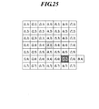
- FIG. 25 is a diagram illustrating an example in which defective pixels are interpolated by radiation detecting elements existing at positions outside the region when the radiation detecting elements (7, 6) are defective pixels in the example of FIG.
- It is a flowchart which shows the process sequence of the image generation using a radiographic image detector. It is a figure which shows the structure of the radiographic image generation system containing the defect image determination system which concerns on this embodiment.
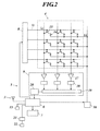
- the radiation image detector (flat panel detector) 1 includes a housing 2 that protects the inside, and radiates irradiated radiation to the inside of the radiation incident surface X of the housing 2.
- a scintillator layer (not shown) for conversion into (1) is formed.
- the scintillator layer for example, a layer formed using a phosphor in which a luminescent center substance is activated in a matrix such as CsI: Tl, Gd 2 O 2 S: Tb, ZnS: Ag, or the like can be used.
- each photodiode 14 is connected to a TFT 15 which is a signal reading switch element.
- the so-called indirect radiation image detector 1 that converts radiation into light by the scintillator layer and detects it by a photoelectric conversion element such as a photodiode as described above will be described.
- a so-called direct-type radiation image detector that directly converts the radiation incident on the detection element without passing through the scintillator layer into an electrical signal. The invention can be applied.
- the detection elements used in these types of radiation image detectors are collectively referred to as radiation detection elements. That is, for example, in the indirect radiation image detector 1 as in the present embodiment, the radiation detection element includes one photodiode 14, a TFT 15 connected thereto, and a portion corresponding to the photodiode 14 in the scintillator layer.
- a direct radiation image detector includes a detection element and a switch element such as a TFT connected thereto.
- the radiation image detector 1 has a built-in battery 21 (see FIG. 2). As shown in FIG. 1, in this embodiment, an antenna device 3 that is a wireless communication unit is embedded in the battery replacement lid member 10 provided on the side surface portion of the housing 2 of the radiation image detector 1. Is provided. Further, a power switch 11 of the radiation image detector 1 and indicators 12 for displaying various operation statuses are provided on the side surface of the housing 2.
- the reading unit 5 includes a control unit 6 including a microcomputer, a storage unit 7 including a ROM (Read Only Memory) and a RAM (Random Access Memory), a flash memory, a scan driving circuit 8, a reading circuit 9, and the like. ing.
- the plurality of radiation detection elements arranged two-dimensionally on the sensor panel unit 4 respectively have a position x in the row direction and a position y in the column direction of the radiation detection elements in the sensor panel unit 4.
- the coordinates (x, y) for each component are assigned in advance as the number (x, y) of the radiation detection element.
- radiation detection elements (x, y) when individual radiation detection elements are specified, they are referred to as radiation detection elements (x, y).
- FIG. 3 8 ⁇ 16 radiation detection elements (x, y) are illustrated, but this is a simplified representation, and actually more radiation detection elements (x, y). ) Are two-dimensionally arranged and assigned numbers.
- the coordinates (x, y) (that is, the radiation detection element number (x, y)) may be referred to as a pixel number (x, y) or a pixel position (xy).
- each radiation detection element (x, y) of the sensor panel unit 4 is used for signal readout.
- the source electrode of the TFT 15 which is the switch element is connected.
- a bias line Lb is connected to the other electrode of each radiation detection element (x, y), and the bias line Lb is connected to a bias power supply 16, and each radiation detection element (x, y) is connected from the bias power supply 16.
- a bias voltage is applied to y).
- each TFT 15 is connected to the scanning line Ll extending from the scanning drive circuit 8, and the drain electrode of each TFT 15 is connected to the signal line Lr.
- Each signal line Lr is connected to an amplifier circuit 17 in the readout circuit 9, and an output line of each amplifier circuit 17 is connected to an analog multiplexer 19 via a sample hold circuit 18.
- the analog multiplexer 19 is connected to an A / D converter 20, and the reading circuit 9 is connected to the control means 6 via the A / D converter 20.
- a storage means 7 is connected to the control means 6.
- the radiation image detector 1 in radiation image capturing for capturing a subject (not shown), when radiation transmitted through the subject enters the scintillator layer, light is irradiated from the scintillator layer to the sensor panel unit 4, and the amount of light irradiation received Accordingly, electric charges are accumulated in the radiation detection element (x, y).
- the control means 6 associates the amplified electrical signal output from the radiation detection element (x, y) with the number (x, y) of the radiation detection element (ie, pixel) described above, and captures the actual image data F (x, y). It is stored in the storage means 7 as y).
- the radiation image detector 1 includes the sensor panel unit 4 in which a plurality of radiation detection elements (x, y) are two-dimensionally arranged, the control means 6, the scanning drive circuit 8, the readout circuit 9, and the like.
- the read unit 5 or the like forms image data acquisition means for acquiring the actual image data F (x, y).
- the image data acquisition means of the radiation image detector 1 not only acquires the above-described actual image data F (x, y) but also performs dark reading.
- the gate of each TFT 15 is closed and the radiation image detector 1 is not irradiated with radiation. Keep on. Then, after a predetermined time has elapsed (usually, after the same time as the charge accumulation time in the radiation detection element (x, y) at the time of radiation irradiation), a readout voltage is applied from the scanning line Ll to the gate electrode of the TFT 15. The gate of the TFT 15 is opened, the charge (dark charge) accumulated in each radiation detection element (x, y) is taken out to the signal line Lr, and the output value is amplified by the amplifier circuit 17 in the same manner as described above. Are sequentially output to the control means 6 via the A / D converter 20.
- the electrical signal output from each radiation detection element (x, y) that is not exposed to radiation is a dark reading value.
- the control means 6 stores each electrical signal output from each radiation detection element (x, y) in association with each pixel number (x, y) as a dark read value D (x, y) in the storage means 7. It is supposed to be.
- the scanning line Ll for applying the read voltage to the TFT 15 is sequentially scanned, and the dark read value D (x, y) is read from all the radiation detection elements (x, y).
- each radiation detection element (x, y) is calibrated in order to grasp the output value characteristic variation from each radiation detection element (x, y).
- the radiation image detector 1 is irradiated with radiation without a subject being present, and based on the actual image data F (x, y) output from each radiation detection element (x, y).
- a gain correction value is calculated for each radiation detection element (x, y).
- dark reading is also performed a plurality of times, and in the dark reading, the dark reading value D (x, y) is output from each radiation detection element (x, y) without irradiating the radiation image detector 1 with radiation. Then, an offset correction value is calculated for each radiation detection element (x, y) based on the output dark read value D (x, y).
- the dark read value D (x, y) output from each radiation detection element (x, y) is detected a plurality of times in a state where no radiation is irradiated immediately before or immediately after the radiographing, and the average value thereof is detected.
- the dark read value D (x, y) output from each radiation detection element (x, y) is detected a plurality of times in a state where no radiation is irradiated immediately before or immediately after the radiographing, and the average value thereof is detected.
- an offset correction value (hereinafter referred to as O (x, y)).
- O (x, y) an offset correction value
- each dark read value D k (x, y) output from the radiation detection element (x, y) in each dark reading is an average value D. It is known to fluctuate so as to form a normal distribution of kave (x, y) and standard deviation ⁇ Dk (x, y).
- the average value D kave (x, y) is an average value on the time axis of each dark reading value D k (x, y), this average value is defined as a “temporal average value”. If the average value D kave (x, y) is used as the offset correction value O (x, y) of the radiation detection element (x, y), the value of each dark read value D k (x, y) Since temporal fluctuations can be reduced or offset, in general, the temporal average value of each dark reading value D k (x, y) may be used as the offset correction value O (x, y). Many.
- the offset correction value O (x, y) is shown in the following equation (2).
- the dark reading value D k (x, y) fluctuates with the standard deviation ⁇ Dk (x, y).
- the fluctuation magnitude is generally 1 / ⁇ K. That is, the offset correction value O (x, y) has a distribution having fluctuations of standard deviation ⁇ 1 / ⁇ K ⁇ ⁇ Dk (x, y) ⁇ . Therefore, the above equation (2) indicates that the value of fluctuation 1 / ⁇ K is used as the offset correction value rather than using the dark read value D k (x, y) itself as the offset correction value. Show.
- the offset correction method is described by performing dark reading at least once just before or immediately after radiographic imaging, even if the dark reading is performed only once. , Y) is used.
- the defective pixel determination method according to the present invention is not limited to the offset correction method described below.
- This method (a method of calculating an offset correction value O (x, y) with high accuracy even if dark reading is performed at least once before or immediately after radiographic imaging, and even if dark reading is performed only once. ) Is as follows.
- a plurality of dark images d k (x, y) under a predetermined temperature condition without temperature change (Hereinafter, the dark reading value d k (x, y) is distinguished from the dark reading value D (x, y) obtained by one dark reading performed immediately before or immediately after radiographic imaging as described above.) And an offset correction value ⁇ (x, y) (hereinafter, finally obtained offset correction value O (x, y)) using a plurality of acquired dark images d k (x, y). In order to distinguish from y), an offset correction value ⁇ (x, y) is obtained). It is assumed that the temperature characteristics of each pixel position (x, y) are the same while the dark image d k (x, y) is acquired.
- a temperature compensation variable is defined to represent the amount of change accompanying the temperature change of the signal value at each pixel position (x, y) when the offset correction value ⁇ (x, y) is obtained, and this is defined for each pixel. Calculate and store for each position (x, y).
- the temperature compensation variable is not intended to measure the temperature itself of the radiation detection element (x, y) at each pixel position (x, y). What we want to know is not the temperature itself of each radiation detection element (x, y), but the signal at each pixel position (x, y) due to the temperature change of each element such as the radiation detection element (x, y) or an electric circuit. Because the value has changed (for example, even if the temperature of each radiation detection element (x, y) itself changes), the signal value of the pixel corresponding to that radiation detection element (x, y) changes.
- the variable be a variable that quantitatively suggests how the signal value at each pixel position (x, y) has changed.
- the final image data F O (x, y) is used for calculation.
- the dark read value D (x, y) acquired every time radiographic imaging is not directly used as the offset correction value itself, but the temperature at each pixel position in the temperature environment when radiography is performed. The point used for calculation of the compensation variable is different from the conventional method.
- the time point when the radiographic image is actually taken is reached.
- the point that it is used as the offset correction value O (x, y) after performing the temperature correction is a point that the conventional method does not have.
- an offset correction value ⁇ (x, y) serving as a reference for calculating an offset correction value O (x, y) used to obtain final image data F O (x, y).
- O (x, y) since it is calculated from a plurality of dark images d k (x, y) under a predetermined temperature condition that can be regarded as having no temperature change, error components (temporal fluctuations in signal values) such as electrical noise are canceled out.
- the value is close to the true offset correction value. Therefore, the final image data F with a small correction error and a good S / N ratio as compared with the case where the single dark read value D (x, y) itself acquired at the time of radiographic imaging is used as the offset correction value. O (x, y) can be obtained.
- Requirement 1 Variable required for each pixel unit (or for each small area unit close to a pixel).
- Requirement 2) A variable that can grasp changes in signal value due to temperature changes.
- Requirement 3) A variable obtained from the dark image D (x, y).
- Requirement 4) Variables with little temporal fluctuation.
- the present inventor has calculated the average value (or median value, etc.) of the pixel values of the peripheral pixels with respect to the pixel of interest (x, y) of the dark read value D (x, y). I paid attention to.
- each element such as the radiation detection element (x, y) and the electric circuit being affected by the temperature change is reflected in the dark read value D (x, y).
- D dark read value
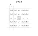
- the one radiation detection element (x, y) that is, in a 5 ⁇ 5 square region centered on the pixel position (x, y).
- the signal values at a plurality of pixel positions (x ⁇ 2, y ⁇ 2) to (x + 2, y + 2) existing in FIG. A method of selecting a radiation detection element (x, y) other than the one radiation detection element (x, y) will be discussed later.
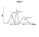
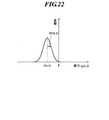
- the distribution of temporal fluctuations in the signal values y-2) to D (x + 2, y + 2) is not always the distribution as shown in FIG. 5, but actually, for example, as shown in FIG. to, the average value mu D and the standard deviation sigma D is different distributions are common.
- the dark reading values D (x ⁇ 2, y ⁇ 2) to D (x + 2, y + 2) are independent variables, and their fluctuations are random in terms of time and space.
- the temporal average value of temporal fluctuations of (x, y) is expressed as ⁇ D (x, y)
- the standard deviation of the temporal fluctuation distribution is expressed as ⁇ D (x, y)
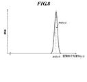
- ⁇ W (x, y) See FIG. 8).
- ⁇ D (x ⁇ 2, y ⁇ 2) to ⁇ D (x + 2, y + 2) is different, but taking an average, it is almost equal to ⁇ D (x, y).
- ⁇ W (x, y) is 1 / ⁇ N of the value of ⁇ D (x, y).
- the standard deviation value of fluctuation has a magnitude N times the standard deviation value ⁇ D (x, y) of temporal fluctuation of the dark read value D (x, y) at the target pixel position. If N> 2, And ⁇ W (x, y) ⁇ D (x, y) Is established.
- the distribution of the spatial average value W (x, y) as the temperature compensation variable is a plurality of radiation detection elements 14 (hereinafter referred to as predetermined regions) in a square region centered on the one radiation detection element (x, y).
- ⁇ W (x, y) becomes small. This means that when ⁇ W (x, y) takes a sufficiently small value, W (x, y) ⁇ W (x, y) (6) It can be approximated.
- the radiation image capturing immediately before or one dark read in the radiation detection element 14 dark read value D output from the R to be performed immediately after (x-2, y-2 ) ⁇ D (x + 2, y + 2) ( hereinafter, in the sense that dark read value output from the radiation detecting element 14 R belonging to a predetermined region R is denoted as dark read value D R.), the time distribution of the temporal fluctuations as illustrated in FIG.
- the one of the radiation detecting element (x, y) be the average value mu D and the standard deviation sigma D of the distribution of the temporal fluctuations of the dark read value D R to be output from the radiation detection elements 14 R are different, including the (see FIG. 7), by calculating their spatial mean value (temperature compensation variable) W (x, y), the temporal fluctuation of the dark read value D R output from the radiation detection elements 14 R is valid
- the spatial variation (temperature compensation variable) W (x, y) is almost equal to the average value ⁇ W (x, y) of the distribution of temporal fluctuations. Can do.
- the average value of temporal fluctuations that cannot be obtained unless a plurality of dark readings are performed is the spatial average value W (x, y) of the dark reading values D (x, y) obtained by one dark reading. y) can be substituted with a small error.
- the radiation detection elements (x ′, y ′) other than the one radiation detection element (x, y) when calculating the temperature compensation variable W (x, y) for the one radiation detection element (x, y). ) Will be described.
- the radiation detection element (x, y) In the radiation detection element (x, y), the radiation detection element (x, y) is usually output when the temperature of the radiation detection element (x, y) or the reading circuit for reading out the signal value is low.
- the dark read value D (x, y) is a small value, and as the temperature T of the radiation detection element (x, y) increases, the output dark read value D (x, y) also increases. It is known. Therefore, for example, the average value ⁇ D (x, y) of the temporal fluctuation distribution of the dark read value D (x, y) output from each radiation detection element (x, y) as shown in FIG. As the temperature rises, it shifts to the right on the graph in the figure.
- each radiation detection element (x, y) on the sensor panel unit 4 and elements of the readout circuit The temperature variation is not uniform.
- the radiation detection element (x, y) at the center of the sensor panel unit 4 in which a large number of radiation detection elements (x ′, y ′) are present around the sensor panel unit 4 The radiation detection element (x, y) in the peripheral portion has a different temperature variation method, and the temperature variation method differs if the readout IC constituting the readout circuit is different. Even within the same readout IC, if the amplifier circuit 17 is different, the manner of temperature variation is different.
- the radiation detection element (x ′, y ′) for example, when a radiation detection element (x ′, y ′) far from the one radiation detection element (x, y) on the sensor panel unit 4 is selected, its temperature It is predicted that the fluctuation is different from the temperature fluctuation of the one radiation detection element (x, y).
- the dark reading value D (x ′, y ′) output from each radiation detection element (x ′, y ′) in the left-right direction depends on the temperature of the distribution of temporal fluctuations.
- the degree of shift is different from the degree of shift of the temporal fluctuation distribution of the dark reading value D (x, y) of the one radiation detection element (x, y), and the relative positions on the graph are respectively It fluctuates depending on the temperature of the pixel position.
- the spatial average value (temperature compensation variable) W (x, y) is the temporal average value ⁇ W of the spatial average value (temperature compensation variable) W (x, y). The beneficial effect of being approximately equal to (x, y) cannot be used.
- the spatial average value (temperature compensation variable) W (x, y) for one radiation detection element (x, y) from the result of one dark reading performed immediately before or after radiographic imaging As a radiation detection element (x ′, y ′) other than the one radiation detection element (x, y) for calculating the radiation detection, a radiation detection that changes in temperature in the same manner as the one radiation detection element (x, y).
- the element (x ′, y ′) is selected in advance and is associated with the one radiation detection element (x, y) in advance.
- the selection method may be different for each radiation detection element.
- a selection method for example, as described above, a plurality of radiation detection elements (x, y) R existing in an n ⁇ n square region centered on the one radiation detection element (x, y) are selected.
- the square region is not necessarily set so that the one radiation detection element (x, y) exists at the center. It does not have to be.
- the size of the square area is 5 ⁇ 5 or 7 ⁇ 7 (refer to the description in FIGS. 24 to 26 to be described later), but the size is limited to this size. Not what you want. As long as the size is larger than 1 ⁇ 1, it may be 2 ⁇ 2, 3 ⁇ 3, or 9 ⁇ 9 or larger. In addition, a rectangular area can be set instead of the square area, or an indefinite area can be used.
- the radiation detection elements (x ′, y ′) other than the one radiation detection element (x, y) are radiation detection elements that change in temperature in the same manner as the one radiation detection element (x, y). Well, it is scattered on the sensor panel unit 4 instead of the radiation detection elements (x, y) R existing in the spatially continuous region including the one radiation detection element (x, y) as described above. It may be a radiation detection element (x, y).
- the detection element group exhibiting the same temperature characteristics can be grasped in advance during factory inspection or the like. It can also be reset after the establishment of the facility.
- x ⁇ 2, y ⁇ 2) to D (x + 2, y + 2) also include temporal fluctuations, and based on these, the offset correction value O (1) of the one radiation detection element (x, y) is directly selected. The true value of x, y) cannot be obtained.
- the dark detection is performed a plurality of times at the time of past calibration (performed before radiography of the current subject), and the one radiation detection element (x, y)
- a dark reading value d (x, y) output from itself is obtained, and first, a plurality of dark reading values d (x, y) output from one radiation detection element (x, y) are obtained.
- a temporal average value ⁇ (x, y) is calculated.
- a temperature compensation variable from each of the plurality of radiation detection elements (x, y) in the square region centered on the one radiation detection element (x, y) in each dark reading at the time of past calibration.
- Spatial average value of dark reading value d to be output (hereinafter, spatial average value W (x, y) as a temperature compensation variable obtained by one dark reading performed immediately before or after the above radiographic imaging)
- w (x, y) a spatial average value as a temperature compensation variable obtained at the time of calibration
- w (x, y) a spatial average value w (x, The time average value ⁇ (x, y) for a plurality of times of y) is calculated.
- x, y) is used to calculate the offset correction value O (x, y) of the one radiation detection element (x, y).
- the term “calibration” refers not only to the calibration for updating both the gain correction value and the offset correction value that are performed periodically (for example, every month) as described above, but also compared with the gain correction value. Also included is offset calibration that is performed only when necessary, with respect to offset correction values with large dynamic temperature fluctuations.
- calibration refers to the dark reading value D (x, x, as necessary) when the radiation image detector 1 is shipped from the factory, introduced into the facility, or during standby when radiation is not exposed. This is an operation for acquiring and creating all or part of the data for correcting the photographed image data F (x, y) including y) in advance, rather than the calibration performed periodically as described above. It is a broad concept.
- the calibration after introduction into the facility may be performed with a shorter cycle (for example, every day) than the periodic calibration.
- dark reading is usually performed a plurality of times.
- the dark reading value d (x, y) from which these values are calculated is the value obtained by the dark reading from the present to the predetermined number of times or the latest (that is, It is preferable to use a value obtained by a plurality of dark readings performed in the previous calibration or offset calibration.
- the process of calculating the temporal average value ⁇ (x, y) or the like from the dark read value d (x, y) may be performed by the radiation image detector 1 or from the radiation image detector 1 to the console 31 ( It is also possible to transmit the dark reading value d (x, y) to an external device such as FIG.
- the temporal average value ⁇ (x, y) of each dark read value d (x, y) of the one radiation detection element (x, y) itself obtained by the above-mentioned multiple times of dark reading is as follows. Is calculated according to the following equation (7).
- M represents the number of dark read values d m (x, y) used for calculating the temporal average value ⁇ (x, y) or the like, that is, the predetermined number of times.
- the distribution is in a normal distribution with the temporal average value ⁇ (x, y) as the center and the standard deviation ⁇ d (x, y). This distribution represents the temporal fluctuation of the dark reading value d m (x, y).
- the temporal average value ⁇ (x, y) of the dark read value d (x, y) output from the one radiation detection element (x, y) in a plurality of dark readings at the time of past calibration is considered.
- the temporal average value ⁇ (x, y) of the spatial average value w (x, y) as the temperature compensation variable and one dark reading performed immediately before or after the current radiographic image capturing is considered.
- the temperature T in the vicinity of the radiation detection element (x, y) or the radiation detection element (x, y) on the sensor panel unit 4 when radiographic imaging is performed is not necessarily calibrated as shown in FIG. It is not the temperature T 0 during the operation.
- the power consumption state is set to the sleep mode automatically or manually in order to reduce power consumption.
- the temperature T of the radiation detection element (x, y) and the like rises in the imageable mode, and the sensor panel unit 4 in the sleep mode (see the portion S in the figure).
- the temperature T of the radiation detection element (x, y) or the like decreases.
- the dark read value D (x, y) that is normally output when the temperature T of the radiation detection element (x, y) or the like is low is small. As the temperature T of the radiation detection element (x, y), etc. increases, the dark read value D (x, y) output also increases.
- distribution of temporal fluctuation estimated for spatial average value W as a temperature compensation variable is the mean value of the values D R (x, y) also increases or decreases the temperature T.
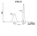
- the distribution of the dark reading value D (x, y) in FIG. 14 and the distribution of the spatial average value W (x, y) as the temperature compensation variable are varied on the horizontal axis in FIG. Fluctuates left and right.
- the distribution tends to shift to the right on the horizontal axis, and when the temperature T falls, the distribution tends to shift to the left on the horizontal axis.
- the distribution of fluctuations such as the dark reading value D (x, y) output from one radiation detection element (x, y) in one dark reading performed immediately before or immediately after the current radiographic image capturing is as follows. Since it is only estimated, it is displayed with a broken line in FIG.
- the temperature of the radiation detection element (x ′, y ′) R including the one radiation detection element (x, y) similarly varies. Therefore, the position on the graph of FIG. 14 of the fluctuation distribution estimated for the dark read value D (x, y) output from the one radiation detection element (x, y) and the one radiation detection element ( x, it is estimated for radiation detection element associated with y) (x, y) spatial average value W as a temperature compensation variable is the mean value of the dark read value D R to be output from the R (x, y)
- the relative positional relationship of the temporal fluctuation distribution with respect to the position on the graph should not change even if the temperature fluctuates.
- the average value ⁇ D (of the temporal fluctuation distribution estimated for the dark read value D (x, y) shown in FIG. x, y) and the average value ⁇ W (x, y) of the temporal fluctuation distribution estimated for the spatial average value W (x, y) as the temperature compensation variable are the past calibrations shown in FIG.
- the temporal average of the distribution of the dark reading values D (x, y) of the one radiation detection element (x, y) obtained by one dark reading performed immediately before or immediately after the current radiographic image capturing is expressed as ⁇ (x, y)
- ⁇ (x, y) ⁇ D (x, y) ⁇ W (x, y) (11) Is the temporal average value ⁇ (x) of the distribution of a plurality of dark reading values d m (x, y) obtained by a plurality of dark readings at the time of past calibration shown in FIG.
- ⁇ D (x, y) can be estimated if only the temperature compensation variable W (x, y) calculated from one dark image can be calculated.
- the average value ⁇ D (x, y) of the temporal fluctuation distribution estimated for the dark read value D (x, y) is exactly the radiation detection element (x, y).
- Offset correction value O (x, y) can be regarded as a true value.
- O (x, y) ⁇ (x, y) + W (x, y) (15) Can be rewritten.
- the temperature of each element in the radiation image detector 1 at the time of calibration has been assumed to be constant.
- the number of dark images acquired the above-described M
- the temperature of each element in the radiation image detector 1 also varies during calibration.
- ⁇ m (x, y) d m (x, y) ⁇ w m (x, y) (18)
- ⁇ m (x, y) is a temperature-corrected dark in which the temperature change of the dark read value d m (x, y) at the time of calibration is corrected by the temperature compensation variable w m (x, y).
- the reading value ⁇ m (x, y) can be considered.
- ⁇ (x, y) that is the average value (temporal average value) of the temperature-corrected dark read value ⁇ m (x, y) is obtained.
- ⁇ (x, y) can be called a temporal average value of temperature-corrected dark reading.
- the temperature-corrected dark reading value ⁇ m (x, y) and the temperature-corrected dark reading temporal average value ⁇ (x, y) are used for dark reading at the time of calibration and also at the time of radiographic imaging. It can be applied to all operations that are performed multiple times and take the average (temporal average). Moreover, even if the value of M, which is the number of time averages, is large, it can be made less susceptible to temperature fluctuations.
- Similar temperature compensation can be applied when obtaining the gain correction value G (x, y) during calibration.
- G (x, y) radiation image data in a state where the subject is not placed is acquired with a predetermined radiation dose determined in advance, and offset correction is performed on this to obtain the gain correction value.
- the gain correction subjected to the temperature correction similar to the present method is performed.
- Data G (x, y) can be obtained.
- a highly accurate gain correction value G (x, y) can be obtained, and as a result, good image data with a high SN ratio can be obtained.
- each dark read value d m (x, y) output from the radiation detection element (x, y) in M dark readings during calibration a temporal average is obtained.
- the value ⁇ (x, y) is calculated, and further, the standard deviation ⁇ d (x, y) of the distribution is calculated, d m (x, y) ⁇ (x, y) (20) d m (x, y) / ⁇ d (x, y) (21) Or (D m (x, y) ⁇ (x, y)) / ⁇ d (x, y) (22)
- It is also possible to normalize each dark read value d m (x, y) by performing the above-described calculation and configure the above processing based on each normalized dark read value.
- the radiation detection element (x, y) is associated in advance.
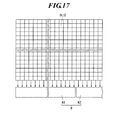
- the other radiation detection elements (x ′, y ′) may be any element that varies in temperature in the same manner as the one radiation detection element (x, y), and the method for selecting them is as described above. There can be various methods. Here, an example of a selection method according to the practical configuration of the radiation image detector 1 will be described.
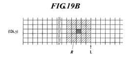
- Y + 2) is shown.
- the one radiation detection element (x, y) is in the peripheral portion of the sensor panel unit 4, the one radiation detection element (x, y) is centered in a square area of 5 ⁇ 5, for example. ) May not be located.
- the position of the one radiation detection element (x, y) represented by being deeply colored in the drawing may be selected.
- the radiation detection element (x, The region R for y) is set in the same manner.
- the numbers described above and to the left of each radiation detection element represented in a lattice pattern are the positions in the row direction and the column direction of each radiation detection element (x, y), respectively.
- the left coordinate (x, y) represents the coordinate of the radiation detection element (x, y).
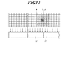
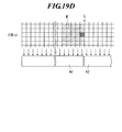
- the readout circuit 9 for reading out and amplifying an electrical signal from each radiation detection element (x, y) normally has 128 pixels or 256 pixels of radiation in the row direction.
- One readout IC 91, 92,... Is connected to each detection element (x, y), and the necessary number of them are arranged in parallel.
- the offset correction value O (x, y) of each radiation detection element (x, y) is the readout IC 91. , 92,...
- a read IC that reads an electrical signal from each radiation detection element belonging to the region R set to calculate the offset correction value O (x, y) of the radiation detection element (x, y).
- the values of the temperature compensation variables W (x, y) and ⁇ (x, y) are set for each radiation detection element (x, y) belonging to the region R. There may be an error, and the offset correction value O (x, y) may not be calculated satisfactorily.
- 19A and 19B show a case where a plurality of radiation detection elements associated in advance with one radiation detection element (x, y) are selected in the normal manner shown in FIG. 6 and the like. .
- defective pixels are detected by carrying out post-manufacturing shipping inspections and inspections involving radiation irradiation during periodic calibration, and the pixel positions of the detected defective pixels are registered in the defective pixel map, As described above, it is operated and managed in association with the radiation image detector.
- a pixel that constantly outputs a large pixel value for example, a pixel whose signal value always reaches a saturation level
- a pixel that constantly outputs only a small pixel value for example, a signal value that always remains
- an abnormal pixel that outputs an abnormal signal value at a certain probability, and whether or not these abnormal pixels are detected accurately without irradiation and whether they are defective pixels or not.
- a method of registering abnormal pixels in the defective pixel map a method of appropriately processing abnormal pixels as abnormal pixels without registering them in the defective pixel map, or in image data irradiated with radiation This is a method for dealing with the abnormal pixels.
- defective pixels are automatically used based on dark reading values (reading signals that do not require radiation irradiation) acquired at the time of calibration or before and after radiographic imaging, or based on user instructions. Determination and abnormal pixel determination are performed. Also, a method for determining defective pixels in consideration of temperature fluctuations of each element in the radiation image detector when determining defective pixels and abnormal pixels will be described. In addition, a method for detecting abnormal pixels from image data obtained by irradiating radiation and appropriately handling them will be described.
- Abnormal pixels that are classified according to the intensity of the value (guideline indicating how abnormal) and the frequency of output of abnormal values are determined to be unacceptable or should not be permitted are registered in the defective pixel map as defective pixels. Do.
- the abnormal pixel Even if a pixel suddenly outputs an abnormal value, if it is determined that the intensity of the abnormal value (a guideline indicating how abnormal) or the frequency of outputting the abnormal value is an acceptable level, the abnormal pixel The same processing (correction processing, etc.) as that of the defective pixel is performed, but it is allowed not to register the defective pixel in the defective pixel map. Of course, all abnormal pixels may be registered as defective pixels in the defective pixel map.
- the gain correction value G (x, y) is calculated by irradiating with radiation at the time of calibration, but the offset correction value O (x, y) can be calculated without irradiating with radiation. It is a parameter.
- the inventors pay attention to the dark read value D (x, y) or dark read value d m (x, y) used for calculation of the offset correction value, and detect abnormal pixels generated at a certain probability as dark read values.
- a method of finding and determining from D (x, y) or dark read value d m (x, y) and processing as a defective pixel or an abnormal pixel (in some cases, registering an abnormal pixel as a defective pixel in a defective pixel map) I found it.
- the present inventors also found a method for detecting abnormal pixels in radiographic image data and appropriately processing them.
- a fluctuation (variation) occurs in y), and the fluctuation distribution is a normal distribution having a standard deviation ⁇ (x, y) around the mean value ⁇ (x, y).
- the average value ⁇ (x, y) of the distribution is a dark read value D (x ′, y ′) output from another radiation detection element (x ′, y ′).
- Distribution is far from the average value ⁇ (x ′, y ′) or the fluctuation is very large, that is, the standard deviation ⁇ (x, y) of the distribution is different from that of the other radiation detection elements (x ′, y). In some cases, it is much larger than the standard deviation ⁇ (x ′, y ′) of the distribution of the dark reading value D (x ′, y ′) output from “′).
- the stability of the finally obtained image data F O (x, y) is also deteriorated and becomes an abnormal value that can be regarded as a defective pixel. May end up.
- the radiation detection element (x, y) that can be regarded as a defective pixel in this way is represented as a defective pixel (xs, ys).
- the standard deviation ⁇ (x, y) of the dark reading value D (x, y) falls within the normal range, there are pixels that occasionally output an abnormal value. Such pixels cannot be detected even if attention is paid only to the standard deviation ⁇ (x, y) of the dark read value D (x, y).
- the pixel that occasionally outputs an abnormal value is also regarded as an abnormal pixel if it exceeds the allowable range. .
- the defective pixel (xs, ys) is determined from the occurrence probability and the degree of abnormality. It is determined whether or not to be registered in.
- the control means 6 that is a computer of the radiation image detector 1 described above and a defective pixel determination device that is a computer of a defective pixel determination system 30 described later (that is, a console 31 described later)
- the server means 39 realizes this defective pixel determination function, that is, the defective pixel determination function described in detail below, and part or all of the processing is performed on the radiation image detector 1 or the console. Needless to say, it may be performed in the server 31 (or the server means 39).
- the dark read value d m (x, y) output from the radiation detection element (x, y) itself in the dark reading performed a plurality of times (M times) at the time of past calibration.
- a plurality of times (M times) of data is accumulated for each radiation detection element (x, y).
- Temporal statistical values such as the temporal average value ⁇ (x, y) and standard deviation ⁇ d (x, y) of the temporal fluctuation distribution.
- the dark read value d m (x, y) output from one radiation detection element (x, y) obtained in the dark reading performed a plurality of times at the time of past calibration is thus obtained.
- temporal statistical values such as temporal average value ⁇ (x, y) and standard deviation ⁇ d (x, y) in the distribution of temporal fluctuations of dark reading value d m (x, y).
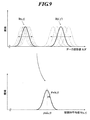
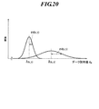
- Dark read value d m (x, y) of the temporal fluctuation standard deviation .sigma.d (x, y) in the distribution of that large, dark read value d m (x, y) output an abnormal value with some probability Therefore, if it is larger than a preset threshold value ⁇ dth, it is determined as a defective pixel (xs, ys) and is registered in the defective pixel map. Can solve the problem.
- the standard deviation in the fluctuation distribution of the dark read value d m (x, y) output from one radiation detection element (x, y) obtained in the dark reading performed a plurality of times during the past calibration.
- ⁇ d (x, y) is equal to or less than the threshold ⁇ dth, that is, ⁇ d (x, y) ⁇ ⁇ dth (23) If so, the fluctuation (variation) in the dark read value d m (x, y) of the one radiation detection element (x, y) is within an allowable range, and is determined to be a normal pixel. In this case, the one radiation detection element (x, y) is not registered as a defective pixel.
- Y) is an average standard deviation in the temporal fluctuation distribution of the dark read value d m (x, y) output from the normal radiation detection element (x, y) shown in the normal distribution on the left side of FIG.
- the temporal fluctuation (variation) of the dark read value d m (x, y) of the one radiation detection element (x, y) exceeds the allowable range and is determined to be a defective pixel. Is done.
- the one radiation detection element (x, y) is registered in the defective pixel map as a defective pixel (xs, ys).
- the threshold value ⁇ dth is, for example, 3 of the average standard deviation ⁇ d (x, y) in the distribution of temporal fluctuations of the dark reading value d m (x, y) output from the radiation detection element (x, y).
- the value is preferably set to about 10 to 10 times, but is not limited to this value.
- variance ⁇ d 2 (x, y) is used instead of the standard deviation ⁇ d (x, y), a threshold is set for the variance ⁇ d 2 (x, y), and processing is performed in the same manner as described above. Is also possible.
- a temporal statistical value a temporal average value ⁇ (x, y) in a temporal fluctuation distribution of the dark read value d m (x, y) output from one radiation detection element (x, y) is used.
- the second threshold ⁇ th2 If it is smaller than ⁇ th2 (hereinafter referred to as the second threshold ⁇ th2), it can be considered that the one radiation detection element (x, y) has a defect, so this is regarded as a defective pixel (xs , Ys) can be determined and registered.
- the time of the dark read value d m (x, y) output from one radiation detection element (x, y) obtained in dark reading performed a plurality of times (M times) at the time of past calibration.
- the temporal average value ⁇ (x, y) in the fluctuation distribution is equal to or higher than the second threshold ⁇ th2 and lower than the first threshold ⁇ th1, that is, ⁇ th2 ⁇ ⁇ (x, y) ⁇ ⁇ th1 (25) If so, the magnitude of the dark read value d m (x, y) output from the one radiation detection element (x, y) is output from the other radiation detection element (x * , y * ).
- the magnitude of the dark read value d m (x * , y * ) does not change so much and is within the allowable range and is determined to be a normal pixel. In this case, the one radiation detection element (x, y) is not registered as a defective pixel.
- the temporal average value ⁇ (x, y) in the temporal fluctuation distribution of the dark read value d m (x, y) output from one radiation detection element (x, y) is obtained. Is greater than the threshold ⁇ th1, that is, ⁇ (x, y)> ⁇ th1 (26) Or the temporal average value ⁇ (x, y) in the temporal fluctuation distribution of the dark read value d m (x, y) output from one radiation detection element (x, y) is small, If it is smaller than the threshold ⁇ th2, that is, ⁇ (x, y) ⁇ th2 (27) Is satisfied, the magnitude of the dark read value d m (x, y) output from the one radiation detection element (x, y) is output from the other radiation detection element (x * , y * ).
- the difference between the dark read value d m (x * , y * ) and the read value is large and exceeds the allowable range, and is determined to be a defective pixel.
- the one radiation detection element (x, y) is registered in the defective pixel map as a defective pixel (xs, ys).
- the value of the dark reading value d m (x, y) itself being too large indicates that there is a high possibility that the dark reading value d m (x, y) will output an abnormal value with a certain probability in the future. Because there, defective pixel (xs, ys) is larger than the threshold value d m th set in advance is determined as the, is possible to solve the problem of the present invention by registering the defective pixel map is recognized as problems it can.
- the value of the dark read value d m (x, y) output from one radiation detection element (x, y) obtained in dark reading performed a plurality of times (M times) at the time of past calibration is obtained.
- the magnitude of the dark read value d m (x * , y * ) does not change so much and is within the allowable range and is determined to be a normal pixel. In this case, the one radiation detection element (x, y) is not registered as a defective pixel.
- the magnitude of the dark read value d m (x, y) output from the one radiation detection element (x, y) is output from the other radiation detection element (x * , y * ).
- the difference between the dark read value d m (x * , y * ) and the read value is large and exceeds the allowable range, and is determined to be a defective pixel.
- the one radiation detection element (x, y) is registered in the defective pixel map as a defective pixel (xs, ys).
- the dark read value d output from the radiation detection element (x, y) itself in the dark reading performed a plurality of times (M times) at the time of past calibration.
- M times m (x, y) is used to determine whether or not the one radiation detection element (x, y) is a defective pixel from the temporal statistical value. That is, during the dark reading period that is performed a plurality of times (M times), the signal value output from the radiation detection element (x, y) is not affected by the temperature change, or the signal value is not affected by the temperature change. It was considered small enough to be ignored.
- the signal value output from the radiation detection element (x, y) is affected by a temperature change during a plurality of (M times) dark reading periods, it is more accurate to compensate for this temperature change. A good judgment can be made.
- the dark read value d output from one radiation detection element (x, y) itself.
- the one radiation detection element (x, A method for determining whether or not y) is a defective pixel and registering it will be described in [Determination Method 4] to [Determination Method 6].
- the determination method described here is a method in which the concept of temperature compensation is incorporated in the above [determination method 1].
- each dark read value d m (x ′, y ′) output from a plurality of radiation detection elements (x ′, y ′) previously associated with the one radiation detection element (x, y).
- the average value w m (x, y) is output from the one radiation detection element (x, y) itself in order to determine whether or not the one radiation detection element (x, y) is a defective pixel. Since it is used in contrast with the dark read value d m (x, y), a plurality of radiation detection elements (x ′, y ′) that are targets for calculating the spatial average value w m (x, y).
- a plurality of other radiation detection elements that are associated with the one radiation detection element (x, y) in advance and change in temperature in the same manner as the one radiation detection element (x, y). ) Is selected as described above.
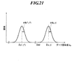
- the one of the radiation detecting element (x, y) is the defective pixel (xs, ys) If, dark read value output from the one radiation detection device (xs, ys) d m ( xs, ys) Since the fluctuation itself is much larger than that in the case of a normal pixel, the distribution of temporal fluctuation (variation) of the difference e m (xs, ys) has a large standard deviation ⁇ e (xs, ys) as shown in FIG. It becomes a distribution of normal distribution having
- the standard deviation ⁇ e (x, y) is larger than a preset threshold ⁇ eth.
- the one radiation detection element (x, y) can be determined as a defective pixel (xs, ys) and registered.
- the above threshold ⁇ eth as in the case of the threshold ⁇ dth described above, for example, 3 times to 10 times the average standard deviation ⁇ e in the distribution of the temporal fluctuations of the difference e m (x, y) ( x, y) Although it is preferable to set to a value of about, it is not limited to this value. Further, the variance ⁇ e 2 (x, y) is used instead of the standard deviation ⁇ e (x, y), a threshold is set for the variance ⁇ e 2 (x, y), and processing is performed in the same manner as described above. Is also possible.
- the difference e m (x, y) is a variable obtained by performing temperature compensation with w m (x, y) on the dark read value d m (x, y) as shown in the equation (30). Therefore, the error due to the temperature change of the dark reading value d m (x, y) is canceled out. Accordingly, the standard deviation ⁇ e (x, y) of the temporal fluctuation of the difference e m (x, y) is equal to the standard deviation ⁇ d (x, y) of the temporal fluctuation of the dark read value d m (x, y). And ⁇ e (x, y) ⁇ ⁇ d (x, y) (32) The relationship is established.
- Determination method 5 The determination method described here is a method in which the concept of temperature compensation is incorporated into the above-mentioned [determination method 2].
- the temporal average value ⁇ (x, y) of the temperature-corrected dark reading is larger than a preset threshold value ⁇ th1 (hereinafter, referred to as a first threshold value ⁇ th1), or is larger than the threshold value ⁇ th1.
- a preset threshold value ⁇ th1 hereinafter, referred to as a first threshold value ⁇ th1
- the threshold value is smaller than another threshold value ⁇ th2 (hereinafter referred to as the second threshold value ⁇ th2) set to a small value
- the one radiation detection element (x, y) is determined as a defective pixel (xs, ys), and the defect is detected. It is configured to be registered in the pixel map.
- the difference ⁇ (x, y) obtained in the dark reading performed a plurality of times (M times) at the time of the past calibration is not less than the second threshold ⁇ th2 and not more than the first threshold ⁇ th1, that is, ⁇ th2 ⁇ ⁇ (x, y) ⁇ ⁇ th1 (33) If so, the magnitude of the dark read value d m (x, y) output from the one radiation detection element (x, y) is output from the other radiation detection element (x * , y * ).
- the dark read value d m (x * , y * ) does not vary greatly and is determined to be within the allowable range and to be a normal pixel. In this case, the one radiation detection element (x, y) is not registered as a defective pixel.
- the temporal average value ⁇ (x, y) of the temperature-corrected dark reading is larger than the threshold value ⁇ th1, that is, ⁇ (x, y)> ⁇ th1 (34)
- the temporal average value ⁇ (x, y) of the temperature-corrected dark reading is smaller than the threshold value ⁇ th2, that is, ⁇ (x, y) ⁇ th2 (35) Is satisfied, the magnitude of the dark read value d m (x, y) output from the one radiation detection element (x, y) is output from the other radiation detection element (x * , y * ).
- the difference between the dark read value d m (x * , y * ) and the read value is large and exceeds the allowable range, and is determined to be a defective pixel.
- the one radiation detection element (x, y) is registered in the defective pixel map as a defective pixel (xs, ys).
- the temporal average value ⁇ (x, y) of the dark corrected temperature reading is the temporal average value ⁇ (x, y) of the dark reading value d m (x, y) as shown in the equation (12). Therefore, the error due to the temperature change of the dark read value d m (x, y) is canceled out.
- [Determination Method 5] is a method with less error with respect to temperature change than [Determination Method 2].
- the determination method described here is a method in which the concept of temperature compensation is incorporated into the above-mentioned [determination method 3]. That is, as a temporal statistical value used for determination, instead of each dark reading value d m (x, y), it is the absolute value of the difference e m (x, y) defined by the equation (30)
- the dark read value d m (x, y) output from one radiation detection element (x, y) obtained in the dark reading performed a plurality of times (M times) at the time of past calibration and the spatial Similar to the other radiation detection elements (x * , y * ), the absolute value of the difference e m (x, y) of the average value w m (x, y) is equal to or less than the threshold value e m th, that is,
- the magnitude of the dark read value d m (x * , y * ) does not change so much and is within the allowable range and is determined to be a normal pixel. In this case, the one radiation detection element (x, y) is not registered as a defective pixel.
- the absolute value of one radiation detecting element (x, y) the difference e m calculated for (x, y) is larger than the threshold value e m th, i.e.,
- the difference between the dark read value d m (x * , y * ) and the read value is large and exceeds the allowable range, and is determined to be a defective pixel.
- the one radiation detection element (x, y) is registered in the defective pixel map as a defective pixel (xs, ys).
- a pixel that exceeds a predetermined threshold is not immediately registered as a defective pixel, but is registered as a defective pixel depending on, for example, the number of times (frequency). You may make it determine whether to do. Further, a plurality of threshold values are set at a predetermined interval, a histogram (the number of abnormal pixels entering a predetermined interval) for each interval is calculated, and the interval position and the occurrence frequency of abnormal pixels in the interval are calculated. Accordingly, it may be determined whether or not to register a defective pixel.
- the standard deviation ⁇ d (x, y) is, for example, in the fluctuation distribution of the dark read value d m (x, y).
- a radiation detection element that is significantly large, the temporal average value ⁇ (x, y) in the fluctuation distribution is an abnormal value, or the dark read value d m (x, y) itself is an abnormal value ( It is possible to accurately find x, y), accurately determine that the radiation detection element (x, y) is a defective pixel, and register it in the defective pixel map.
- the offset correction value O (x, y) is calculated, or the actual image data F (x, y) is corrected to obtain the final image data F O.
- the offset correction value O (x, y) is calculated, or the actual image data F (x, y) is corrected to obtain the final image data F O.
- the dark read value d m (x, y) output from the radiation detection element (x, y) increases or decreases due to temperature fluctuation.
- [Determination Method 4], [Determination Method 5], and [Determination Method 6] from each radiation detection element (x, y) itself for each dark reading at the time of past calibration.
- a difference ⁇ m (x, y) from the spatial average value w m (x, y) of the read value d m (x ′, y ′) is calculated, and based on the difference, the one radiation detection element (x, y) is calculated. ) Is a defective pixel.
- the radiation detection element (x, y) is removed in the state where the influence of the value variation due to the temperature variation of the dark read value d m (x, y) is removed. It is possible to determine whether or not the pixel is a defective pixel, and the defective pixel can be found more stably without being affected by the temperature.
- [Decision method 1] to [determination method 3] or [determination method 4] to [determination method 6] can be used independently to register defective pixels, but [determination method 1] to [Determination Method 3] or a combination of [Determination Method 4] to [Determination Method 6], for example, [Determination Method 1] and [Determination Method 3] or [Determination Method 4] and [Determination Method 6] , [Determination Method 1], [Determination Method 2], [Determination Method 3] or [Determination Method 4], [Determination Method 5], and [Determination Method 6] are used to register defective pixels with higher accuracy. It can be performed.
- the dark read value D (x, y) immediately before and after the radiographing is offset.
- the dark read value D (x, y) is offset.
- the dark read value D (x, y) is offset.
- the dark read value D m (x, y) is offset.
- the average value of m (x, y), the dark reading value D (x, y) or the dark reading value D m (x , Y), or the average value of the dark read values D m (x, y) is determined as an abnormal value, and defective pixels can be determined and registered.
- the recognized abnormal pixel value may be a sudden phenomenon that occurs very rarely, or the abnormal value may be registered as a defective pixel. In some cases, it is difficult to determine whether something comes out frequently.
- the absolute value of the difference E (x, y) is expressed as
- the absolute value
- the difference E (x, y) between the dark read value D (x, y) output from one radiation detection element (x, y) immediately before and after radiographic imaging and the spatial average value W (x, y). ) Is equal to or smaller than the threshold Eth, similarly to the other radiation detection elements (x * , y * ), that is,
- the magnitude of the dark read value D (x, y) output from the one radiation detection element (x, y) is the dark output from the other radiation detection element (x * , y * ).
- the read value D (x * , y * ) is not much different from the size of the read value D (x * , y * ) and is within the allowable range, and is determined to be a normal pixel.
- the magnitude of the dark read value D (x, y) output from the one radiation detection element (x, y) is output from the other radiation detection element (x * , y * ).
- the dark read value D (x * , y * ) is greatly different from the allowable range and is determined to be an abnormal pixel.
- the difference E (x, y) is a variable obtained by performing temperature compensation with W (x, y) on the dark read value D (x, y) as shown in the equation (38). The error due to the temperature change of the dark reading value D (x, y) is cancelled.
- the one radiation detection element (x , Y) can be regarded as having an abnormality, so that it is determined as an abnormal pixel and temporarily stored.
- the absolute value of the difference ⁇ (x, y) is equal to or less than the threshold value ⁇ th, like the other radiation detection elements (x * , y * ), that is,
- the read value D (x * , y * ) is not much different from the size of the read value D (x * , y * ) and is within the allowable range, and is determined to be a normal pixel.
- the magnitude of the dark read value D (x, y) output from the one radiation detection element (x, y) is output from the other radiation detection element (x * , y * ).
- the dark read value D (x * , y * ) is greatly different from the allowable range and is determined to be an abnormal pixel.
- the difference ⁇ (x, y) is an arithmetic operation between the difference ⁇ (x, y) and the difference E (x, y), both of which are temperature compensated, as shown in the equation (41). Therefore, the error due to the temperature change of the dark read value D (x, y) is cancelled.
- any of the following options 1) to 5) can be employed for handling abnormal pixels shown in [Determination method 7] and [Determination method 8].
- Option 1 It is regarded as an abnormal pixel that occurs accidentally and is not registered as a defective pixel.
- Option 2) Immediately register in the defective pixel map as defective pixel (xs, ys).
- Option 3) Decide whether or not to register as a defective pixel according to the value of the abnormal pixel value. That is, when the value of an abnormal pixel is very large (when a threshold value for determining registration to a defective pixel determined separately is exceeded), it is registered in the defective pixel map as a defective pixel (xs, ys).
- Option 4 As an abnormal pixel, a pixel position is stored separately from the defective pixel.
- the occurrence probability is determined at that time and determined in advance.
- the generated occurrence probability threshold value is exceeded, it is registered in the defective pixel map as a defective pixel (xs, ys).
- Option 5 The above options 3) and 4) are combined.
- ing if there is a sudden abnormal pixel that is not registered as a defective pixel in the spatial average value w m (x, y) or the spatial average value W (x, y), the temperature compensation coefficient There is a concern that the accuracy of the value of the value decreases.
- the dark reading values (D (x, y) and D m (x, y) and d m (x, y)) surrounding the target pixel position (x, y) of I s the spatial average value of N pixel values, and even if there is a sudden abnormal pixel that is not registered as a defective pixel among the N peripheral pixels, the effect is reduced to 1 / N.
- a separate means may be provided to detect sudden abnormal pixels and exclude them from the pixels used for calculating the temperature compensation variable.
- the pixel of the actual image data F (x, y) If a sudden abnormal pixel is included in the value, the abnormal pixel is also recognized in the final image data F O (x, y), which is not preferable. Therefore, it is preferable to take appropriate measures not only for defective pixel correction but also for abnormal pixels that occur suddenly for the real image data F (x, y).
- the photographed image data F (x, y) has the following characteristics, it is not as easy to handle as the dark reading values described so far.
- the photographed image data F (x, y) needs to be handled as the photographed image data F (x, y) that has been radiographed only once. In some cases, the same subject is photographed multiple times. In this case, since the subject is moved or the direction of the subject is changed during multiple radiographic image capturing, each of the independent photographed image data F (x , Y).
- Radiation image capturing for acquiring actual image data F (x, y) is solid image capturing for acquiring gain correction data (solid image capturing is a uniform radiation without placing a subject. Except for shooting that is irradiated), the subject is always placed and the subject image is reflected in the real image data F (x, y).
- the value of the actual image data F (x, y) accurately reflects subject information. It is difficult to judge objectively whether or not there is. For example, if radiation image capturing under the same conditions is performed a plurality of times on the same subject (assuming that the subject does not move during the plurality of capturing operations), a plurality of times are performed for a predetermined pixel position (x, y). By comparing the variations in image data, it can be determined whether or not subject information is reflected almost accurately from a statistical point of view.
- the average value of the signal values of the pixel position (x, y) in multiple radiographic imaging is calculated and the variation of each signal value from the average value is measured, if there is little variation, those signal values Can be determined to reflect the subject information almost accurately.
- the signal value is The subject information is not accurately reflected, and it can be determined that the pixel is an abnormal pixel affected by noise or the like.
- each pixel value the value that each pixel value should be, that is, the true value of each pixel value. For example, if it is a dark reading value, it can be determined by statistical processing as described above whether the current data is normal or abnormal with respect to a plurality of data acquired at the time of calibration. There is no way to make the same determination for the real image data F (x, y) that is taken only once.
- each pixel value of the live-action image data F (x, y) varies depending on the radiation absorption rate of the subject, but this is a signal value that changes very gently from a microscopic viewpoint of the pixel size level.
- the normal pixel size is often selected in the range of 100 to 200 microns, and the pixel size exceeding 200 microns is often not selected even though the selection is 100 microns or less).
- the signal value changes in the direction in which the signal value attenuates.
- abnormal pixels to be affected here act so that the signal value becomes large (abnormalities that act so that the signal value becomes small are already registered as defective pixels), so they act in the direction of absorbing radiation. A lesion that does not get confused with an abnormal pixel.
- the pixel that occurs suddenly is always an isolated pixel.
- abnormal pixels that occur suddenly have a low frequency of occurrence (those with a high frequency of occurrence are already registered as defective pixels), and one flat panel detector usually has a pixel count of around 5 megapixels. Therefore, the probability that the sudden abnormal pixels in question are generated side by side or as a clustered cluster is astronomically small.
- the sudden abnormal pixel taken up as a problem this time is always generated as an isolated pixel.
- the case where they occur next to each other or the case where they occur as a cluster-like lump may be taken into consideration.
- the sudden abnormal pixels in the actual image data F (x, y), which are the subject of this study, are considered to have the following properties.
- An abnormal pixel always has a large signal value (behaves like a pixel irradiated with a lot of radiation) 2) An abnormal pixel is an isolated point. The pixels around the abnormal pixel are always normal pixels other than those registered as defective pixels. 3) A normal pixel changes smoothly in the direction in which the signal value increases, and does not show a large pixel change in units of one pixel.
- the one radiation detection element (x, y), that is, the pixel position (x, y) as the plurality of radiation detection elements (x, y) is set as the target pixel position of the actual image data.
- 25 pixel positions (x ⁇ 2, y ⁇ 2) to (x + 2, y + 2) existing in a 5 ⁇ 5 square area centered on the pixel position (x, y) are defined as comparison areas.
- the comparison area selection method is not limited to this.
- the comparison region is not necessarily a square region.
- the comparison area may be four pixels above and below the pixel position (x, y), or the comparison area may be two pixels above and below the pixel position (x, y) or left and right.
- V (x, y) F (x, y) ⁇ A (x, y) (45)
- V (x, y) is less than or equal to a preset threshold value Vth, that is, V (x, y) ⁇ Vth (46) If so, the value of the actual image data F (x, y) output from the one radiation detection element is used as it is without being changed.
- V (x, y) when the difference V (x, y) is larger than a preset threshold value Vth, that is, V (x, y)> Vth (47) If so, the photographed image data F (x, y) output from the one radiation detection element is determined as an abnormal pixel, and the photographed image is obtained with the average value B (x, y) defined in the equation (49). The value of data F (x, y) is replaced (see equation (48)). F (x, y) ⁇ B (x, y) (48)
- the calculation comparison area selection method is not limited to this.
- the calculation region is not necessarily a square region. In order to reduce the number of calculations, the calculation area may be four pixels above and below the pixel position (x, y), or the calculation area may be two pixels above and below the pixel position (x, y).
- comparison area A (x, y) and the calculation area B (x, y) are individually defined (the comparison area and the calculation area do not necessarily match), but the comparison area A (x , Y) and the calculation area B (x, y) may be treated as the same. If a defective pixel exists in the comparison area or calculation area, the average value A (x, y) or average value B (x, y) can be calculated using normal pixels adjacent to the defective pixel. good.
- the abnormal pixel in the actual image data F (x, y) is described as having a large signal value (behaves like a pixel irradiated with a lot of radiation). Also, the case where the signal value changes in a decreasing direction may be considered. That is,
- An abnormal pixel always has an abnormal value in a direction of increasing or decreasing with respect to surrounding pixel values.
- An abnormal pixel is an isolated point.
- the pixels around the abnormal pixel are always normal pixels other than those registered as defective pixels.
- Normal pixels change smoothly and do not show large pixel changes in units of one pixel. Judgment may be made.
- for V (x, y) in the equation (45) is defined, and this absolute value
- the radiation image detector 1 is uniformly irradiated with radiation in a state where no subject is present, and the actual image data F (x, y) is transmitted from each radiation detection element (x, y). y) is output, and the abnormal pixel is determined in the same manner as in the above [determination method 10] based on each photographed image data F (x, y) acquired in a state where the subject does not exist. be able to.
- the radiation incident surface X (see FIG. 1) of the radiation image detector 1 is irradiated with radiation so as to have a substantially constant dose over the entire surface, and each radiation detection element (x, It is assumed that the actual image data F (x, y) having substantially the same signal value is to be output from y).
- V (x, y) is calculated according to the above equations (44) and (45) for the actual image data F (x, y) actually output from each radiation detection element (x, y). Then, an absolute value
- is larger than a preset threshold value V′th, that is,
- the abnormal pixel changes in the direction in which the pixel value of the offset correction value O (x, y) or the photographed image data F (x, y) increases, so that the offset correction is performed in the calculation result of the above formula (1). If there is an abnormal pixel in the value O (x, y), the signal value of the final image data F O (x, y) changes in a decreasing direction, and the actual image data F (x, y) has an abnormal pixel. For example, the signal value changes in the direction in which the signal value of the final image data F O (x, y) increases.
- the dark average read value output from the radiation detection element of the radiation image detector or the signal value of the actual image data is the spatial average value of the signal values output from the plurality of radiation detection elements associated therewith.
- the value is an abnormal value far from the above, it is possible to accurately determine that the radiation detection element is an abnormal pixel. And if the information of the one radiation detection element determined to be an abnormal pixel is temporarily stored in the storage means, even if the pixel is not registered in the defective pixel map as a defective pixel, it is temporarily defective. It is possible to perform correction processing that corrects abnormal values of abnormal pixels themselves by interpolation processing using the surrounding pixel values as if they were defective pixels, so that abnormalities are included in the final image data. It is possible to effectively prevent the generation of pixels.
- the one radiation detection element (target pixel) for calculating the spatial average value W (x, y) as a temperature compensation variable is radiation.
- the detection element (4, 4) is associated with 7 ⁇ 7 radiation detection elements (1, 1) to (7, 7) centered on the radiation detection element (4, 4).
- a case where the radiation detection element (6, 6) is a defective pixel will be described.
- the simplest calculation method includes a plurality of radiation detection elements (1, 1) to (7, 7) associated in advance with the one radiation detection element (4, 4) including the defective pixel (6, 6). 7) Using the dark reading values D (1, 1) to D (7, 7) output from 7), It is conceivable to calculate the spatial average value W (4, 4) of the radiation detection element (4, 4) by the above. However, with this calculation method, there is a possibility that W (4, 4) is affected by the dark read value D (6, 6) of the defective pixel (6, 6).
- [Calculation method 2] Output from the radiation detection elements excluding the defective pixel (6, 6) among the plurality of radiation detection elements (1, 1) to (7, 7) previously associated with the one radiation detection element (4, 4). Using only the dark read values D (1,1) to D (7,7) (except for D (6,6)), Thus, the spatial average value W (4, 4) of the radiation detection element (4, 4) can be calculated.
- the dark reading value D (6, 6) output from the defective pixel (6, 6) is used as the dark reading value output from the radiation detection element (5, 6) in the vicinity of the defective pixel (6, 6).
- the value D (5,6) D (6,6) ⁇ D (5,6) (54) is calculated according to the above equation (52).
- the dark reading value D (6, 6) output from the defective pixel (6, 6) is converted into the radiation detection element (5, 6) adjacent to the defective pixel (6, 6) inside the region R.
- a radiation detection element that exists at a position outside the region R such as the radiation detection element (8, 6) shown in FIG. , 6) can be configured to replace the dark read value D (6, 6) output from the defective pixel (6, 6) with the dark read value D output from the radiation detection element adjacent to the pixel.
- the dark read value D (6, 6) output from the defective pixel (6, 6) is interpolated with each dark read value D output from a plurality of radiation detection elements in the vicinity of the defective pixel (6, 6).
- the spatial average value W (4, 4) may be calculated.
- the dark read value D (6, 6) output from the defective pixel (6, 6) is used as the radiation detection element (5, 5), (6, 5) in the vicinity of the defective pixel (6, 6). , (7,5), (5,6), (7,6), (5,7), (6,7), (7,7) , D (6,5), D (7,5), D (5,6), D (7,6), D (5,7), D (6,7), D (7,7)
- the average value of these values is calculated, and the value of D (6,6) is interpolated with the average value.
- the spatial average value W (4, 4) of the radiation detection element (4, 4) is calculated according to the above equation (52).
- the defective pixel is a radiation detection element (7, 6) present at the end of the region R as shown in FIG. 26, the defective pixel (7, 6) is output.
- the dark read value D (7,6) is calculated from the radiation detection elements (5,5), (6,5), (7,5), (5,6) in the vicinity of the defective pixel (7,6). , (6,6), (5,7), (6,7), (7,7), the dark read values D (5,5), D (6,5), D (7,7) 5), D (5,6), D (6,6), D (5,7), D (6,7), D (7,7) can be used for interpolation. is there.
- radiation detection elements (8, 5), (8, 6), (8) that are radiation detection elements that are located outside the region R and are close to the defective pixel (7, 6). , 7) using the dark read values D (8, 5), D (8, 6), D (8, 7) output from the defective pixels (7, 6).
- the values of (7, 6) are set to the radiation detection elements (6, 5), (7, 5), (8, 5), (6, 6), (8, 6), (6, 7), (7 , 7), (8, 7), the dark read values D (6, 5), D (7, 5), D (8, 5), D (6, 6), D (8, 6) ), D (6, 7), D (7, 7), and D (8, 7) may be used for interpolation.
- the control means 6 composed of a microcomputer or the like is used as the determination means.
- a plurality of determination means are used during calibration.
- y) and the like are compared with a predetermined threshold value d m th, and at least one dark read value d m (x, y) output from the radiation detection element (x, y) is compared with the threshold value d m th.
- the radiation detection element (x, y) is determined as a defective pixel, and is stored in the storage means 7 of the radiation image detector 1 and registered. Is possible .
- the determination unit (that is, the control unit 6) is performed at least once before or immediately after dark reading performed multiple times during calibration or radiographic imaging.
- the dark read value d m (x, y) output from the one radiation detection element (x, y) obtained in the dark reading is associated with the one radiation detection element (x, y) in advance.
- of the difference e m (x, y) from the spatial average value w m (x, y) of each dark reading value output from the plurality of radiation detection elements obtained compares the threshold value e m th predetermined, absolute value of the difference
- the effect of the defective pixel determination method and defective pixel determination program which concerns on this invention mentioned above is exhibited effectively, and it is determined exactly whether a radiation detection element is a defective pixel. For example, by using this method at the time of shipping inspection, the inspection cost can be reduced. If this method is used for calibration after installation in a user facility, newly generated defective pixels can be automatically registered in the defective pixel map without the user irradiating radiation.
- the defective pixel map is updated very easily.
- the radiation image detector 1 is provided with an input button 23 (see FIG. 1) in order to allow the user to input instructions).
- the program of this method operates periodically and newly registered defective pixels are automatically registered in the defective pixel map, even if the user does not instruct each time, The defective pixel map can be updated.
- the dark reading is performed only once after the radiographic image capturing.
- the dark reading may be performed before the radiographic image capturing, and the dark reading is performed about twice. It is also possible to do. It goes without saying that even if the dark reading is performed twice or more, the power consumption increases, but the other effects of the present embodiment can be obtained.
- the image generation using the radiation image detector 1 is performed according to the flowchart shown in FIG. 27, and includes a defective pixel determination step (step S1), a real image data acquisition step (step S2), and a dark reading step. (Step S3), temperature compensation variable calculation step (step S4), temporal average value calculation step (step S5), offset correction value calculation step (step S6), and image correction step (step S7). After that, final image data can be obtained.
- the statistical value is the above-described spatial average value, temporal average value, or the like. However, it is possible to adopt other methods of taking statistical values, which will be described later.
- step S1 based on the above-described defective pixel determination method, the result of dark reading performed a plurality of times at the time of past calibration, or dark performed one or more times immediately before or after radiographic imaging From the result of reading, all of the plurality of radiation detection elements (x, y) arranged two-dimensionally in the sensor panel unit 4 of the radiation image detector 1 automatically or based on a user instruction are defective pixels. Whether or not the pixel is a defective pixel is registered in the defective pixel map stored in the storage unit 7 of the radiation image detector 1.
- the pixel is determined to be abnormal based on the above-described abnormal pixel determination method and the pixel position is not registered in the defective pixel map, it is temporarily regarded as equivalent to the defective pixel and correction processing is performed in the same manner as the defective pixel.
- the information such as the number (x, y) is temporarily stored in the storage means 7 of the radiation image detector 1 and is treated in the following processing as equivalent to a defective pixel.
- step S1 When the defective pixel determination step (step S1) is performed by an external device such as the console 32, it is output from each radiation detection element (x, y) by dark reading at the time of calibration by a wired method or a wireless method.
- the dark reading value d m (x, y) is transmitted to the external device.
- Information such as the number (x, y) of the radiation detection element determined to be a defective pixel is stored and registered in a storage means (not shown) of the console 32 or a storage means 38 (see FIG. 28) of the server means 39.
- step S1 it is also possible to configure the defective pixel determination step (step S1) to be performed after the actual image data acquisition step (step S2), the dark reading step (step S3), or the like.
- the radiographic image detector 1 is illustrated with a subject part such as a patient's hand or chest (not shown) placed or approached on the radiation incident surface X (see FIG. 1) side.
- Ordinary radiation irradiation is performed by irradiating radiation from a radiation generator that does not.
- the radiation image detector 1 uses a photoconductive material such as a-Se as a detection means to directly convert radiation energy into charges, and this charge is converted into a two-dimensionally arranged TFT or the like.
- a photoconductive material such as a-Se as a detection means to directly convert radiation energy into charges, and this charge is converted into a two-dimensionally arranged TFT or the like.
- An indirect method for reading out an electrical signal by a TFT or the like is well known.
- the radiation image detector 1 is an indirect method, the radiation transmitted through the subject is converted into light by the scintillator layer 3 and is incident on a plurality of radiation detection elements (x, y) arranged in pixel units. Then, after being photoelectrically converted by the radiation detection element (x, y), it is read out as an electric signal in units of pixels, and actual image data F (x, y) is generated. If the radiation image detector 1 is a direct system, the radiation transmitted through the subject is directly converted into electric charges by a photoconductive material such as a-Se, and read out as an electrical signal in units of pixels by the plurality of radiation detection elements 14. Actual captured image data F (x, y) is generated.
- the actual image data F (x, y) is sequentially read as an output value from each radiation detection element (x, y) (each pixel), and each radiation is detected by the control means 6 of the radiation image detector 1.
- the detection element number (x, y) and each photographed image data F (x, y) are associated with each other and stored in the storage unit 7.
- step S3 subsequently, dark reading is performed at least once after radiographic imaging. That is, the read voltage is sequentially applied to each scanning line Ll of the radiation image detector 1 in the state where no radiation is irradiated, and the charge accumulated in each radiation detection element (x, y) is converted into the dark read value D (x, y).
- each dark read value D (x, y) is associated with the number (x, y) of each radiation detection element by the control means 6 of the radiation image detector 1 and stored in the storage means 7. Saved in.
- the abnormal pixel determination program stored in the storage unit 7 is read, and the abnormal pixel determination method described above (see [Determination Method 7] to [Determination Method 11]) is executed in accordance with the program, and the actual image obtained is obtained. Based on the image data F (x, y) and the dark read value D (x, y), it is determined whether or not each radiation detection element (x, y) is an abnormal pixel.
- the number (x, y) is temporarily stored in the storage means 7 and determined as an abnormal pixel according to the above equation (48) or the like.
- the photographed image data F (x, y) output from the radiation detection element (x, y) is replaced with a normal value (a value interpolated with surrounding pixel values) and stored in the storage means.
- a temperature compensation variable calculation step (step S4), a temporal average value calculation step (step S5), an offset correction value calculation step (step S6), and an image correction step (step S7) described later are performed by an external device such as the console 31.
- the actual image data F (x, y) and the dark read values D (x, y) associated with the number (x, y) of each radiation detection element are respectively obtained by a wired method or a wireless method. It is transmitted from the radiation image detector 1 to an external device.
- step S4 the dark read value D (x, y) output from one radiation detection element (x, y) on the sensor panel unit 4 and the one radiation detection element (x , Y), and the dark read values D (x) output from the plurality of radiation detection elements (x ′, y ′) associated with the one radiation detection element (x, y) in advance.
- W (x, y) is calculated.
- the temperature compensation variable W (x, y) is calculated for all the radiation detection elements (x, y) arranged two-dimensionally on the sensor panel unit 4.
- the dark read value D (xs, ys) output from the defective pixel using any one of [Calculation method 1] to [Calculation method 4] described above is radiation in the vicinity thereof.
- the temperature compensation variable W (x, y) of the one radiation detection element (x, y) is calculated by replacing or interpolating with the dark reading value output from the detection element.
- the dark reading output from one radiation detection element (x, y) itself obtained in the dark reading performed a plurality of times (M times) at the time of past calibration.
- a time average value ⁇ (x, y) of M times of the value d m (x, y) is calculated according to the above equation (7).
- the temporal average value ⁇ (x, y) of M times of the spatial average value w m (x, y) of the read value d m (x ′, y ′) is determined according to the above equation (9) or (10). Calculated.
- This temporal average value calculation step (step S5) is not necessarily performed after the temperature compensation variable calculation step (step S4), or after the actual image data acquisition step (step S2) and the dark reading step (step S3). It is not necessary to be arranged, and it is also possible to configure so as to be performed in advance at an appropriate timing.
- the offset correction value described above is obtained from the actual image data F (x, y) read from each radiation detection element (x, y) in the above-described actual image data acquisition step (step S2).
- the actual image data F (x, y) is corrected by subtracting each offset correction value O (x, y) calculated for each radiation detection element (x, y) in the calculation step (step S6).
- the real image data F (x, y), the offset correction value O (x, y), and the gain correction value G (x, y) calculated in advance for each radiation detection element (x, y) are obtained.
- final image data F O (x, y) is generated for each radiation detection element (x, y).
- the characteristic variation for each pixel is corrected with respect to the actual captured image data F (x, y) generated in the actual captured image data acquisition step (step S2).
- Image data F O (x, y) is generated.
- the dark read value d m (x) output from one radiation detection element (x, y) itself obtained by dark reading at the time of past calibration processed in the offset correction value calculation step (step S6). , Y), the actual image data F (x, y) processed in the image correction step (step S7), and the like, are data output from the radiation detection elements that are determined to be defective pixels and registered.
- the data output from the defective pixel may be subjected to processing such as replacement or interpolation in the same manner as the method for calculating the spatial average value when there is a defective pixel. It is performed appropriately.
- offset correction value O (x, y) acquisition of each radiation detection element (x, y) of the radiation image detector 1 mentioned above dark reading will be carried out before or after radiographic imaging. It is possible to acquire an effective offset correction value O (x, y) that approximates the true value for each radiation detection element (x, y) of the radiation image detector 1 by performing at least once.
- the number of times of dark reading can be suppressed to at least one.
- pixels radiation detection elements (x, Since only the final image data F O (x, y) whose characteristic variation for each y)) is corrected needs to be transmitted only once, there is no need to transmit the dark read value D (x, y) or the like. Thus, it is possible to reduce power consumption required for data transmission.
- the radiation image detector 1 is the built-in battery, even when the image data F O (x, y) and such that the wireless communication, since the transmission of the image data F O (x, y) is only once, It is possible to reduce power consumption and prevent the internal battery 21 from being consumed. Further, an effective offset correction value O (x, y) equivalent to that of the conventional method is acquired for each radiation detection element (x, y), and good image data F O (x, y) can be obtained. Become.
- the defective pixel determination step (step S1) by using the defective pixel determination method according to the above-described embodiment, it is accurately determined whether or not the radiation detection element is a defective pixel, and is determined to be a defective pixel. Since the offset correction value O (x, y) is calculated by performing appropriate processing such as replacement and interpolation on the registered radiation detection element, the effective offset correction value O (x, y) is calculated. Can be obtained accurately. Therefore, it is possible to improve the SN ratio of the finally obtained image data F O (x, y).
- the radiation detection element (x, y) is associated with the dark reading before or after the radiation image capturing.
- a spatial statistical value is calculated as a temperature compensation variable W (x, y) that is a spatial average value of the dark read values D (x ′, y ′) output from the plurality of radiation detection elements (x ′, y ′).
- the temporal average value ⁇ (x, y) of the dark read value d m (x, y) output from the radiation detection element (x, y) in a plurality of dark readings in the past calibration and Spatial average value w m (x) of dark read values d m (x ′, y ′) output from a plurality of radiation detection elements (x ′, y ′) associated with the radiation detection elements (x, y).
- Y The case where the temporal statistical value is calculated as the temporal average value ⁇ (x, y) has been described.
- the one radiation detection element is weighted so that the weight for each dark read value (x ′, y ′) output to the radiation detection element (x ′, y ′) closer to (x, y) is larger.
- a plurality of dark reading values d m output from one radiation detection element (x, y) itself.
- the temperature compensation variables w m (x ′, y ′) which are a plurality of spatial statistics values of y ′
- the darker readings d m (x, y) and spatial statistics are obtained for data closer to the present in time. It is possible to weight the value w m (x ′, y ′) so as to increase the weight and calculate the weighted average value as a temporal statistical value.
- a plurality of dark reading values d m (x, y) output from one radiation detection element (x, y) itself or the one radiation detection element (x, y) are associated in advance.
- the median value of a plurality of spatial statistical values w m (x ′, y ′) of each dark read value d m (x ′, y ′) output from the plurality of radiation detection elements (x ′, y ′). May be calculated as a temporal statistical value.
- weighted average value and the median value are used instead of the spatial average value w m (x, y) and the spatial average value W (x, y) used in the above defective pixel determination method. Is possible.
- the defective pixel determination system 30 is constructed in a radiation image generation system including a radiation image detector 1 (see FIG. 1 and the like), a console 31, and server means 39, as shown in FIG. ing.
- a radiation image detector 1 see FIG. 1 and the like
- server means 39 server means 39, as shown in FIG. ing.
- the console 31 functions as a defective pixel determination device that determines a defective pixel
- the server unit 39 or the like can be configured to have the function of a defective pixel determination device. is there.
- the radiation image detector 1 is used by being loaded into a holding portion 33a of a bucky device 33 provided in the photographing room R1.
- the bucky device 33 is provided with a small operation unit 33b similar to a portable information terminal.
- one radiation source 34a of the radiation generator 34 is shared and used by the respective bucky devices 33, and the radiation image detector 1 is loaded into the bucky device 33 and used.
- the radiation generation timing control of the radiation generator 34 is linked with the control means 6 of the radiation image detector 1, and the radiation generator 34
- Various controls of the radiation image detector 1 are performed based on the timing of radiation generation.
- each radiation source 34a of the radiation generator 34 is provided in association with each Buckie device 33.
- the radiation image detector 1 can be used alone in a free state without being loaded into the bucky device 33.
- the radiographic image detector 1 can be used on the bed-type bucky device 33, or the patient can use the radiographic image detector 1 with his / her hand.
- the radiation image detector 1 is provided with an antenna device 3 (see FIG. 1) which is a communication means for transmitting the dark read value D (x, y) and the like in a wireless manner. Further, the radiation image detector 1 is connected to an electrode (not shown) provided on the holding unit 33a when the radiation image detector 1 is loaded on the holding unit 33a of the bucky device 33, and the dark read value D (x, The terminal 13 (see FIG. 2) which is a communication means for transmitting y) etc. in a wired manner and a power supply means to the radiation image detector 1 is present in the antenna device 3 and the power switch 11 of the radiation image detector 1. It is provided in the side part opposite (facing) to the side part of the housing 2 to be operated. Further, a terminal 22 which is a power supply means for charging the battery 21 is provided on the same side surface portion as the terminal 13.
- the radiation image detector 1 when the radiation image detector 1 is loaded in the bucky device 33, the terminal 13 and the electrode of the holding unit 33 a are connected, and the dark read value D (x, y) and the like are transmitted via the cable 32. It is sent to the relay terminal 35 in a wired manner and is sent to the console 31 via the relay terminal 35.
- the radiographic image detector 1 is configured to supply power from the relay terminal 35 to the radiographic image detector 1 via the cable 32 and the terminal 13 when the radiographic image detector 1 is loaded in the bucky device 33.
- the dark read value D (x, y) or the like is transmitted via the antenna device 3 in a wireless manner.
- the radiographing room R1 is provided with a relay terminal 35 including a radio antenna 36 that relays when the radiological image detector 1 communicates the dark read value D (x, y) or the like to the console 31 in a wireless manner.
- Information such as the dark reading value D (x, y) transmitted from the antenna device 3 of the radiation image detector 1 by the wireless method is received by the wireless antenna 36 and transmitted to the console 31 via the relay terminal 35. It has become so.
- the radiographic image detector 1 is supplied with power from the relay terminal 35 via the cable 32 and the terminal 13 when loaded in the bucky device 33, but when used alone, the built-in battery 21 is used. It is designed to operate with the power of Note that the relay terminal 35 is provided with a terminal which is a power supply means (not shown) for charging the battery. When the terminal 22 of the radiation image detector 1 is brought into contact with the terminal on the relay terminal 35, the relay terminal 35 is not shown. Electric power is supplied to the battery 21 of the radiation image detector 1 via the terminal 22 and the battery 21 is charged. However, it is not limited to this form.
- a tag (not shown) is built in the radiation image detector 1.
- a so-called RFID (Radio Frequency IDentification) tag is used as the tag, and the tag includes a control circuit that controls each part of the tag and a storage unit that stores unique information such as the ID of the radiation image detector 1. Built in compact.
- a tag reader 37 that reads the RFID tag of the radiation image detector 1 is installed.
- the tag reader 37 transmits predetermined instruction information on radio waves or the like via a built-in antenna (not shown), detects the radiation image detector 1 entering or leaving the front chamber R2, and detects the radiation image detector 1 An ID or the like is transmitted to the console 31.
- a radiation image is formed on the outer surface of the housing of the radiation image detector 1.
- a bar code in which the ID of the detector 1 and the like are written may be attached and read with a bar code reader.
- the tag reader 37 becomes a barcode reader, reads the barcode of the radiation image detector 1 entering or leaving the front chamber R2, and transmits the ID of the radiation image detector 1 to the console 31.
- the tag reader 37 and the barcode reader are installed in the vicinity of the entrance of the imaging room R1 instead of in the vicinity of the entrance of the front room R2, and the entrance / exit of the radiation image detector 1 to the imaging room R1 is managed. good.
- the radiation image detector 1 is informed of which radiation generating device (by which the radiation image detector 1 enters or leaves the anterior chamber R2 or the radiographing room R1 is notified to the console 31. In the case of this example, it is possible to automatically notify the console 31 and the radiation generator 34 of whether or not it is necessary to link with the radiation generator 34).
- Such management of entering or leaving the radiographic image detector 1 using the RFID or barcode functions effectively in a facility where there are a plurality of radiographing devices and radiation generators.
- the user may directly input information on entering or leaving the radiographic image detector 1 into the imaging room or the like to the console 31.
- the front chamber R2 is provided with a console 31 that controls the defective pixel determination system 30 and the entire radiation image generation system.
- the console 31 includes main units of the relay terminal 35, the tag reader 37, and the radiation generator 34 described above. 34 b and the like are connected, and a bucky device 33 and the like are connected via the relay terminal 35.
- the console 31 includes a computer (not shown) such as a CPU (Central Processing Unit), ROM, RAM, storage means such as a hard disk, and an input / output interface connected to the bus.
- a computer such as a CPU (Central Processing Unit), ROM, RAM, storage means such as a hard disk, and an input / output interface connected to the bus.
- CPU Central Processing Unit
- ROM Read Only Memory
- RAM Random Access Memory
- storage means such as a hard disk
- an input / output interface connected to the bus.
- the server 31 is connected to the console 31 via a network NW.
- the server means 39 is connected to a storage means 38 composed of a hard disk or the like.
- each radiation detection element (x, Information on which radiation detection element (x ′, y ′) is associated with y) is stored in advance in association with the ID of the radiation image detector 1.
- the dark reading values D (x, y) and D m (x, y) obtained in the dark reading performed one or more times immediately before or after are transmitted by the wired method or the wireless method
- the ID of the radiation image detector 1 it is stored in its own storage means or the storage means 38 of the server means 39.
- the server means 39 stores them in the storage means 38 and also stores the radiation detector 1 of the radiation detector 1.
- the temporal average value ⁇ (x, y) of the dark read value d m (x, y) output from each radiation detection element (x, y) and the radiation detection element (x, y) are associated with each other.
- the statistical value (temporal average value) ⁇ (x, y) is calculated and stored in the storage means 38.
- the dark read value d (x, y) can be stored and the temporal average value ⁇ (x, y) and the like can be calculated and stored by the console 31 or the storage means of the console 31. is there.
- the console 31 reads out a program necessary for executing various processes stored in a storage means such as a ROM or a hard disk, expands it in a work area of the RAM, and executes the process according to the program.
- a storage means such as a ROM or a hard disk
- the above-described defective pixel determination program is stored in a storage unit such as a ROM or a hard disk.
- the console 31 as a defective pixel determination device performs the above defective pixel determination according to the defective pixel determination program.
- the method is supposed to be executed. It should be noted that which of the above-described defective pixel determination methods [Determination Method 1] to [Determination Method 8] is determined as appropriate as to which determination method is executed or a combination of these determination methods.
- the console 31 is matched with ID of the radiation image detector 1 from a memory
- the dark reading value d m (x, y) and the like stored are read out and compared with a predetermined threshold value d m th, and at least one dark reading value d m (x, y) is the threshold value d m. If it is larger than th (see the above equation (29)), the radiation detection element (x, y) is determined as a defective pixel, and the defect stored in its own storage means or the storage means 38 of the server means 39 Register in the pixel map.
- the console 31 when the console 31 performs the defective pixel determination described in [Determination Method 6] among the above-described defective pixel determination methods according to the defective pixel determination program, the console 31 is associated with the ID of the radiation image detector 1 from the storage unit.
- the dark read value d m (x, y) and the like stored in the memory are read out, and the dark read value d m (x, y) and the like output from one radiation detection element (x, y) and the one radiation detection
- the effects of the defective pixel determination method and the defective pixel determination program according to the present invention described above are effectively exhibited, and it is accurately determined whether or not the radiation detection element is a defective pixel.
- the configuration is such that the dark reading value d m (x, y) or the like is automatically transmitted from the radiation image detector 1 to the console 31 at the time of calibration, the user will receive radiation each time.
- the newly generated defective pixel can be automatically registered in the defective pixel map without irradiation.
- the radiographic image detector 1 in response to a user instruction to the console 31, automatically transmits a dark reading value d m (x, y) or the like to the console 31 to automatically operate the program of this method, If a newly generated defective pixel is automatically registered in the defective pixel map, the defective pixel map can be updated very easily and prior to acquisition of the actual image. Furthermore, if the program of this method is periodically operated and newly generated defective pixels are automatically registered in the defective pixel map, even if the user does not give instructions every time, automatically, The defective pixel map can be updated.
- the storage means such as a ROM or a hard disk
- the above-mentioned actual image data acquisition step step S2 in FIG. 27
- dark reading step step S3
- temperature compensation variable calculation step step S4
- temporal average value An image generation program for realizing an equal calculation step (step S5), an offset correction value calculation step (step S6), and an image correction step (step S7) is stored, and the console 31 reads this image generation program.
- the data is expanded in the work area of the RAM, and necessary processes are executed according to the image generation program, and each part of the apparatus is controlled.
- the console 31 receives an instruction for radiographic image capturing from a radiographer, doctor, or the like, the actual image data acquisition step is performed by driving the radiation generator 34 that controls the imaging conditions (tube current, tube voltage, etc.) and the start of irradiation. (Step S2 in FIG. 27) is executed. Further, before or after radiographic imaging, an instruction signal is transmitted to the radiographic image detector 1 so as to perform at least one dark reading, and a dark reading step (step S3) is executed.
- the radiation image detector 1 has its own ID, the actual image data F (x, y) of the radiographic image acquired in the actual image data acquisition step (step S2) and the dark reading step for each radiation detection element (x, y).
- the dark read value D (x, y) acquired in (Step S3) is transmitted to the console 31 by a wired method or a wireless method.
- the console 31 stores them in its storage means.
- the console 31 executes the above-described abnormal pixel determination method (see [Determination Method 7] to [Determination Method 11]) according to the abnormal pixel determination program stored in the storage unit such as a ROM, and the radiation image detector. Whether each radiation detection element (x, y) is an abnormal pixel is determined based on the actual image data F (x, y) and the dark read value D (x, y) transmitted from 1. In the case of executing [Determination Method 11], the radiation image detector 1 is irradiated with radiation from the radiation source 34a of the radiation generator 34 in a state where no subject exists.
- the console 31 temporarily stores the number (x, y) in the storage unit, and the abnormal pixel according to the above equation (48) or the like.
- the console 31 subsequently executes a temperature compensation variable calculation step (step S4).
- the console 31 refers to the ID of the radiation image detector 1 and reads out information of a plurality of radiation detection elements (x ′, y ′) associated with each radiation detection element (x, y ′) from the storage means and outputs them. Using each of the dark read values D (x ′, y ′) thus obtained, a temperature compensation variable W (x, y) is calculated for each radiation detection element (x, y) according to the above equation (3).
- the console 31 associates with another radiation detection element (x, y) in advance.
- the dark read value D (xs, ys) output from the defective pixel is calculated using any one of [Calculation method 1] to [Calculation method 4] described above.
- the temperature compensation variable W (x, y) of the one radiation detection element (x, y) is calculated by replacing or interpolating with the dark reading value output from the radiation detection element in the vicinity thereof.
- the console 31 executes a temporal average value calculation step (step S5) based on data obtained at the time of past calibration or the like in advance, but in this embodiment, the radiographic image detector 1 is in the present embodiment.
- the temporal average value ⁇ (x, y) and the temporal average value ⁇ (x, y) of the spatial average value w m (x, y) as the temperature compensation variable are previously stored in the server means 39 as described above. It is calculated in advance and stored in the storage means 38.
- the console 31 may be configured to calculate these values by itself at this stage.
- the console 31 executes an offset correction value calculation step (step S6).
- the console 31 transmits the ID of the radiation image detector 1 transmitted via the tag reader 37 to the server means 39 via the network NW.
- the server unit 39 determines the temporal average value ⁇ (x, y) of the radiation image detector 1 or the spatial average value w m (x, y) as a temperature compensation variable. Is read from the storage means 38 and transmitted to the console 31.
- the console 31 executes an image correction step (step S7), and each captured image data F (x, y) acquired from each radiation detection element (x, y) in the captured image data acquisition step (step S2). From each offset correction value O (x, y) calculated for each radiation detection element (x, y) in the offset correction value calculation step (step S6), each radiation detection element (x, y) is subtracted from the difference. Is multiplied by a gain correction value G (x, y) that is calculated in advance to generate final image data F O (x, y) for each radiation detection element (x, y).
- each radiation detection element (x, y) is effective.
- An offset correction value O (x, y) is acquired, and there is a characteristic variation for each pixel (radiation detection element 14) with respect to the captured image data F (x, y) generated in the captured image data acquisition step (step S2).
- the final image data F O (x, y) is generated after correction.
- the dark reading needs to be performed at least once and the dark reading value D (x, y) needs to be transmitted at least once.
- the power consumption required for reading and transmitting the dark read value D (x, y) is reduced, and it is possible to prevent the internal battery 21 from being consumed. Further, even when the radiation image detector 1 is used in a wired manner, the number of times of dark reading and the number of transmissions of the dark reading value D (x, y) can be reduced, so that power consumption can be suppressed.
- the radiation detection element is a defective pixel, and it is determined and registered as a defective pixel. It is possible to calculate the offset correction value O (x, y) by performing appropriate processing such as replacement and interpolation on the radiation detecting element, and the effective offset correction value O (x, y) can be accurately determined. Can be obtained. Therefore, it is possible to improve the SN ratio of the finally obtained image data F O (x, y).
- the method has been described as a particularly effective method when the dark reading is performed once before or after the radiographic image capturing.
- the same effect can be obtained even when the dark reading is performed twice or more. be able to.
- the present invention has been described. Needless to say, similar effects can be obtained.
- the radiation detection element (x, y) of the radiation image detector 1 outputs from the defective pixel by using the above-described spatial statistical value (spatial average value) calculation method.
- the obtained dark reading value D is appropriately replaced or interpolated to obtain temperature compensation variables W (x, y) and w m (x ′, y ′) which are effective spatial statistics (spatial average values). It is possible to calculate. Thereby, the offset correction value O (x, y) can be accurately calculated.
- the present invention is not limited to the above-described embodiment, and can be changed as appropriate.
- the concept of the present invention is to select in advance a radiation detection element (x ′, y ′) that varies in temperature in the same manner as one radiation detection element and associate it with the one radiation detection element (x, y) in advance. . Therefore, the radiation detection element itself does not need to be a radiation detection element type as in the above-described embodiment, and is also applied to a radiation image detector including a sensor panel unit in which elements having other structures are two-dimensionally arranged. It goes without saying that it is possible.
- the temperature variation in the pixel unit of the radiation detection element has been described, but even if it is a factor other than the temperature variation, a certain pixel value causes a similar change to a neighboring pixel value. Needless to say, the same effect can be obtained by applying the same method if the fluctuation is small.
- the radiation image detector 1 may be configured to perform all data processing from the correction of the data F (x, y) to the generation of the final image data F O (x, y).
- the dark reading is performed at the time of calibration performed separately from the radiographic image capturing.
- the dark reading value to be performed before or after the radiographic image capturing is stored and stored. You may comprise so that it may be used.
- the dark reading values for a plurality of consecutive radiographic image captures are stored by normalization and the like, and the plurality of dark reading values are used as in the above embodiment.
- a temporal statistical value (temporal average value) ⁇ (x, y) or ⁇ (x, y) may be calculated.
- the offset correction is taken as an example, and the description has been made.
- the gain correction value G (x, y) is obtained, the radiation image detector is subjected to uniform radiation under predetermined conditions.
- the offset correction is also applied to this read value (corresponding to the actual image data F (x, y) in this embodiment).
- the gain correction value O (x, y) is obtained for the above-described reason. Needless to say, the same treatment can be performed and the same effect can be obtained.
- the medical field it may be used for a radiological image detector and a defective pixel determination system for obtaining a diagnostic radiographic image.
- Radio image detector 3 Antenna device (wireless communication means) 4, 5, 6 Sensor panel section, reading section and control means (image data acquisition means) 6
- Control means computer, determination means) 13 terminals (communication means) 14, (x, y) radiation detection element 21 battery 30 defective pixel determination system 31 console (defective pixel determination device, computer) 39
- Server means (defective pixel determination device, computer) D (x, y) dark read value D m (x, y) dark read value d m (x, y) dark read value d m th threshold e m (x, y) the difference e m th threshold F (x, y ) Actual image data w m (x, y) Spatial average value (xs, ys) Defective pixel
Landscapes
- Health & Medical Sciences (AREA)
- Engineering & Computer Science (AREA)
- Life Sciences & Earth Sciences (AREA)
- Medical Informatics (AREA)
- Radiology & Medical Imaging (AREA)
- Biomedical Technology (AREA)
- Biophysics (AREA)
- High Energy & Nuclear Physics (AREA)
- Signal Processing (AREA)
- Nuclear Medicine, Radiotherapy & Molecular Imaging (AREA)
- Optics & Photonics (AREA)
- Pathology (AREA)
- Multimedia (AREA)
- Physics & Mathematics (AREA)
- Heart & Thoracic Surgery (AREA)
- Molecular Biology (AREA)
- Surgery (AREA)
- Animal Behavior & Ethology (AREA)
- General Health & Medical Sciences (AREA)
- Public Health (AREA)
- Veterinary Medicine (AREA)
- Apparatus For Radiation Diagnosis (AREA)
- Transforming Light Signals Into Electric Signals (AREA)
- Solid State Image Pick-Up Elements (AREA)
Abstract
放射線画像検出器の放射線検出素子が欠陥画素か否かを的確に判定することが可能な欠陥画素判定方法、欠陥画素判定プログラム、放射線画像検出器及び欠陥画素判定システムを提供する。 2次元状に配置された複数の放射線検出素子(x,y)を備える放射線画像検出器1における欠陥画素判定方法であって、キャリブレーション時に複数回行われたダーク読取及び/又は放射線画像撮影に際して1回以上行われたダーク読取において得られた一の放射線検出素子(x,y)から出力されたダーク読取値dm(x,y)と、予め定められた閾値dmthとを比較し、当該放射線検出素子(x,y)から出力された少なくとも1つのダーク読取値dm(x,y)が閾値dmthよりも大きい場合に、当該放射線検出素子(x,y)を欠陥画素と判定する。
Description
本発明は、欠陥画素判定方法、欠陥画素判定プログラム、放射線画像検出器及び欠陥画素判定システムに関するものである。
通称フラットパネルディテクタ(Flat Panel Detector:FPD)と呼ばれる固体撮像素子を2次元的に配置した放射線画像検出器には、検出素子として、a-Se(アモルファスセレン)のような光導電物質を用いて放射線エネルギーを直接電荷に変換し、この電荷を2次元的に配置されたTFT(Thin Film Transistor:薄膜トランジスタ)等の信号読み出し用のスイッチ素子によって画素単位に電気信号として読み出す直接方式や、放射線エネルギーをシンチレータ等で光に変換し、この光を2次元的に配置されたフォトダイオード等の光電変換素子で電荷に変換してTFT等によって電気信号として読み出す間接方式等が良く知られている。
そして、いずれの方式においても、被写体を透過してきた放射線を放射線画像検出器で検出して得られた実写画像データに対してゲイン補正やオフセット補正等を行い、実写画像データを補正する必要があることが知られている。
一般的に、実写画像データの補正では、下記(1)式に示される通り、放射線画像検出器の各放射線検出素子(センサパネル部における座標は(x,y))から出力された実写画像データF(x,y)からオフセット補正値O(x,y)を差し引き、その差分にゲイン補正値G(x,y)を乗算することにより、最終的な画像データFO(x,y)を得るようにして補正が行われる。なお、放射線画像検出器の1つの放射線検出素子から出力される実写画像データF(x,y)に基づいて生成される画像データFO(x,y)は、撮影画像(すなわち放射線画像)における1画素分の画像データに相当するため、以下、放射線検出素子のことを画素と呼ぶ場合がある。
FO(x,y)=(F(x,y)-O(x,y))×G(x,y) …(1)
FO(x,y)=(F(x,y)-O(x,y))×G(x,y) …(1)
このように、実写画像データの補正では、オフセット補正値O(x,y)やゲイン補正値G(x,y)を得ることが必要となるため、放射線画像検出器に対してキャリブレーションを定期的に行い、経時的に特性が変動し得るオフセット補正値O(x,y)やゲイン補正値G(x,y)を更新するのが一般的である。
しかしながら、この方法では、キャリブレーションを行った時の放射線画像検出器内の各素子の温度と、放射線画像撮影を実施した時の放射線画像検出器内の各素子の温度が一致していることが前提となるため、キャリブレーションを行った時の放射線画像検出器内の各素子の温度と、放射線画像撮影を実施した時の放射線画像検出器内の各素子の温度が異なる場合は、特に温度依存性の高いオフセット補正値O(x,y)が適正な値からずれてしまい、最終的な画像データFO(x,y)のSN比を劣化させてしまうという問題がある。
この問題を解決するために、放射線画像撮影ごとに、撮影の直前や直後に放射線を照射しない状態で各放射線検出素子からの出力値(以下、ダーク読取値D(x,y)という。また、ダーク読取値をダーク画像と呼ぶ場合がある。)を検出して、当該放射線画像撮影におけるオフセット補正値O(x,y)が算出される場合もある。これは、放射線画像撮影で実写画像データF(x,y)が得られた時点における放射線検出素子の温度特性とできるだけ同じ温度条件下でオフセット補正値O(x,y)を得るための処理である。
しかし、実写画像データF(x,y)を取得する場合と同様に、ダーク読取値D(x,y)を取得する際にも、各種電気ノイズ、すなわち、フォトダイオードの暗電流ノイズ、TFT過渡ノイズ、TFTサーマルノイズ、TFTリークノイズ、TFTから電荷を読み出すデータラインの寄生容量によって生じるサーマルノイズ、読み出し回路内部のアンプノイズ、A/D変換によって生じる量子化ノイズなどが影響するため、仮に同一の温度条件下でダーク読取値D(x,y)を読み取ったとしても、ダーク読取値D(x,y)には、これら電気ノイズに起因する信号値のゆらぎ(ばらつき)が生じる。
そのため、放射線画像撮影の直前や直後にダーク読取値D(x,y)を読み取るとしても、読み取られたダーク読取値D(x,y)の値がすなわちその温度条件等の撮影条件におけるオフセット補正値O(x,y)の真値であるとは必ずしも言えない。そこで、放射線画像撮影の直前や直後にダーク読取を複数回行って各ダーク読取値D(x,y)の平均値を算出し、その平均値をオフセット補正値O(x,y)として採用することがしばしば行われる(例えば特許文献1~3等参照)。
これは、放射線画像撮影の直前や直後に、放射線画像撮影における放射線検出素子等の温度特性と同じ温度条件下で複数回読み出されたダーク読取値D(x,y)の平均値を算出すれば、ダーク読取値D(x,y)のゆらぎが緩和、若しくは相殺されるため、その平均値は、その撮影条件下におけるオフセット補正値O(x,y)の真値に等しく、或いは少なくともそれに近い値となるという考えに基づくものである。そして、その平均値であるオフセット補正値O(x,y)を用いて実写画像データF(x,y)を補正すれば、補正後の最終的な画像データFO(x,y)のSN比を良好なものとすることができる。
一方、このようなオフセット補正をはじめとする補正処理等の画像処理は、従来から、放射線画像検出器等の撮影装置とは異なる画像処理プロセッサやコンソール等の処理装置で行われることも多い(例えば、特許文献4等参照)。また、近年、バッテリを内蔵し、ケーブルを介さずに無線方式により外部の処理装置等との間で実写画像データF(x,y)等の送受信を行うポータブルの放射線画像検出器が開発されている(例えば、特許文献5等参照)。
また、放射線画像検出器では、製造過程において、正常な画素値を出力できない欠陥画素が発生することがある。例えば、欠陥画素の例としては、定常的に大きな画素値を出力する画素(例えば、信号値が常に飽和レベルまで達している画素)や、もしくは定常的に小さな画素値しか出力しない画素(例えば、常に信号値がゼロレベルの値しか出力しない画素)、また、常に一定の信号値しか出力しない画素(放射線を照射しても出力する画素値が変化しない画素)などがある。
これら欠陥画素は、TFT製造過程で発生する場合もあるし、TFT上に光電変換素子を形成する際に発生する場合もある。放射線画像検出器では、照射した放射線量に比例して画素値が適正に変化することが求められるが、これら欠陥画素では、照射した放射線量に応じた正常な画素値の変化は期待できない。
診断画像に対してこのような欠陥画素が発生すると、誤診の原因になったり、診断行為の妨げになるため、欠陥画素が存在する場合は、この欠陥画素を周囲の画素値を用いて補間処理により補正を行い、最終的な画像データFO(x,y)中に欠陥画素が視認できないように処理することが求められる。
このような補正処理を行うためには、予め欠陥画素の画素位置が分かっていなければならない。このような欠陥画素は、製造後の出荷検査や、定期的なキャリブレーション時に放射線照射を伴う検査を実施することで検出され、検出された欠陥画素の画素位置が欠陥画素マップに登録される(例えば、特許文献6参照)。この欠陥画素マップは放射線画像検出器毎に構築され、以後、個々の放射線画像検出器と対応付けて運用、管理される。
前述したオフセット補正、ゲイン補正を行う際にも、この欠陥画素マップが参照され、欠陥画素の画素値をオフセット補正やゲイン補正に誤って使用しないように管理される。
米国特許5452338号明細書
米国特許6222901号明細書
米国特許7041955号明細書
特開平11-113889号公報
特開平7-140255号公報
特開2001-8198号公報
欠陥画素の例として、定常的に大きな画素値を出力する画素(例えば、信号値が常に飽和レベルまで達している画素)や、もしくは定常的に小さな画素値しか出力しない画素(例えば、常に信号値がゼロレベルの値しか出力しない画素)、また、常に一定の信号値しか出力しない画素(放射線を照射しても出力する画素値が変化しない画素)を上げたが、これらの欠陥画素は非常に容易に検出することができる。
しかしながら、上記のいずれにも属さないが、ある確率で異常な信号値を出力する画素(以下、異常画素と呼ぶ。)が存在する。これらの画素は欠陥画素マップに登録されていないため、ある確率で最終的な画像データFO(x,y)中に異常な値を持つ画素を生成させ、診断の妨げとなる危険性があった。
また、これまでの欠陥画素判別方法では、欠陥画素を判別する際、放射線の照射を行った画像情報を用いて欠陥画素を検出していたため、画像生成のために使用される時間の関係で、欠陥画素を判別するために使用する画像数が数枚からせいぜい十数枚に限定されてしまうという問題があった。従って、定常的に異常値を出力する欠陥画素は検出できてもある確率で発生する異常画素を捕まえられなかったり、標準偏差などの統計値を用いて欠陥画素の判別を行う際に、精度の良い統計値を求めることが困難であった。そのため、放射線の照射回数を増やそうとすると生産性が低下し、生産コストが増加するという問題点があった。
また、このような欠陥画素や異常画素は、経時的に増加する傾向にある、そのため、工場出荷時に欠陥画素を登録しておけば安全ということではなく、ユーザー環境に設置後も、定期的にキャリブレーションを行い、新たな欠陥画素や異常画素が発見された場合には、その画素位置を欠陥画素マップに登録したり、異常画素として適切に処理することが好ましい。しかしながら、ユーザー先に設置後に行うキャリブレーション作業においても、定期的にユーザーに複数回の放射線照射を義務づけることになり、ユーザーの作業負荷が増大するという課題があった。
また、キャリブレーション処理により欠陥画素や異常画素を判別する際に、放射線画像検出器内の各素子の温度変動を考慮した欠陥画素や異常画素を判別する方法が提案されていないため、温度変化の影響を受けずに精度良く欠陥画素や異常画素を判定することが困難であった。
本発明は、以上のような課題を解決するためになされたものであり、放射線画像検出器の放射線検出素子が欠陥画素か否かを的確に判定することが可能な欠陥画素判定方法、欠陥画素判定プログラム、放射線画像検出器及び欠陥画素判定システムを提供することを目的とする。
前記の問題を解決するために、本発明の欠陥画素判定方法は、
2次元状に配置された複数の放射線検出素子を備える放射線画像検出器における欠陥画素判定方法であって、
キャリブレーション時に複数回行われたダーク読取及び/又は放射線画像撮影に際して1回以上行われたダーク読取において一の前記放射線検出素子から出力されたダーク読取値と、予め定められた閾値とを比較し、前記一の放射線検出素子から出力された少なくとも1つのダーク読取値が前記閾値よりも大きい場合に、当該一の放射線検出素子を欠陥画素と判定することを特徴とする。
2次元状に配置された複数の放射線検出素子を備える放射線画像検出器における欠陥画素判定方法であって、
キャリブレーション時に複数回行われたダーク読取及び/又は放射線画像撮影に際して1回以上行われたダーク読取において一の前記放射線検出素子から出力されたダーク読取値と、予め定められた閾値とを比較し、前記一の放射線検出素子から出力された少なくとも1つのダーク読取値が前記閾値よりも大きい場合に、当該一の放射線検出素子を欠陥画素と判定することを特徴とする。
また、本発明の欠陥画素判定方法は、
2次元状に配置された複数の放射線検出素子を備える放射線画像検出器における欠陥画素判定方法であって、
キャリブレーション時に複数回行われたダーク読取及び/又は放射線画像撮影に際して1回以上行われたダーク読取において一の前記放射線検出素子から出力されたダーク読取値と前記一の放射線検出素子に予め対応付けられた複数の放射線検出素子から出力された各ダーク読取値の空間的平均値との差分の絶対値と、予め定められた閾値とを比較し、前記差分の絶対値が前記閾値よりも大きい場合に、当該一の放射線検出素子を欠陥画素と判定することを特徴とする。
2次元状に配置された複数の放射線検出素子を備える放射線画像検出器における欠陥画素判定方法であって、
キャリブレーション時に複数回行われたダーク読取及び/又は放射線画像撮影に際して1回以上行われたダーク読取において一の前記放射線検出素子から出力されたダーク読取値と前記一の放射線検出素子に予め対応付けられた複数の放射線検出素子から出力された各ダーク読取値の空間的平均値との差分の絶対値と、予め定められた閾値とを比較し、前記差分の絶対値が前記閾値よりも大きい場合に、当該一の放射線検出素子を欠陥画素と判定することを特徴とする。
また、本発明の欠陥画素判定プログラムは、
コンピュータに、
2次元状に配置された複数の放射線検出素子を備える放射線画像検出器においてキャリブレーション時に複数回行われたダーク読取及び/又は放射線画像撮影に際して1回以上行われたダーク読取において一の前記放射線検出素子から出力されたダーク読取値と、予め定められた閾値とを比較し、前記一の放射線検出素子から出力された少なくとも1つのダーク読取値が前記閾値よりも大きい場合に、当該一の放射線検出素子を欠陥画素と判定する欠陥画素判定機能を実現させることを特徴とする。
コンピュータに、
2次元状に配置された複数の放射線検出素子を備える放射線画像検出器においてキャリブレーション時に複数回行われたダーク読取及び/又は放射線画像撮影に際して1回以上行われたダーク読取において一の前記放射線検出素子から出力されたダーク読取値と、予め定められた閾値とを比較し、前記一の放射線検出素子から出力された少なくとも1つのダーク読取値が前記閾値よりも大きい場合に、当該一の放射線検出素子を欠陥画素と判定する欠陥画素判定機能を実現させることを特徴とする。
また、本発明の欠陥画素判定プログラムは、
コンピュータに、
2次元状に配置された複数の放射線検出素子を備える放射線画像検出器においてキャリブレーション時に複数回行われたダーク読取及び/又は放射線画像撮影に際して1回以上行われたダーク読取において一の前記放射線検出素子から出力されたダーク読取値と前記一の放射線検出素子に予め対応付けられた複数の放射線検出素子から出力された各ダーク読取値の空間的平均値との差分の絶対値と、予め定められた閾値とを比較し、前記差分の絶対値が前記閾値よりも大きい場合に、当該一の放射線検出素子を欠陥画素と判定する欠陥画素判定機能を実現させることを特徴とする。
コンピュータに、
2次元状に配置された複数の放射線検出素子を備える放射線画像検出器においてキャリブレーション時に複数回行われたダーク読取及び/又は放射線画像撮影に際して1回以上行われたダーク読取において一の前記放射線検出素子から出力されたダーク読取値と前記一の放射線検出素子に予め対応付けられた複数の放射線検出素子から出力された各ダーク読取値の空間的平均値との差分の絶対値と、予め定められた閾値とを比較し、前記差分の絶対値が前記閾値よりも大きい場合に、当該一の放射線検出素子を欠陥画素と判定する欠陥画素判定機能を実現させることを特徴とする。
また、本発明の放射線画像検出器は、
2次元状に配置された複数の放射線検出素子と、
被写体を透過した放射線に基づく実写画像データを前記複数の放射線検出素子から取得し、放射線が照射されない状態で行われるダーク読取では前記複数の放射線検出素子からダーク読取値を取得する画像データ取得手段と、
キャリブレーション時に複数回行われた前記ダーク読取及び/又は放射線画像撮影に際して1回以上行われた前記ダーク読取において一の前記放射線検出素子から出力された前記ダーク読取値と、予め定められた閾値とを比較し、前記一の放射線検出素子から出力された少なくとも1つのダーク読取値が前記閾値よりも大きい場合に、当該一の放射線検出素子を欠陥画素と判定する判定手段と、
を備えることを特徴とする。
2次元状に配置された複数の放射線検出素子と、
被写体を透過した放射線に基づく実写画像データを前記複数の放射線検出素子から取得し、放射線が照射されない状態で行われるダーク読取では前記複数の放射線検出素子からダーク読取値を取得する画像データ取得手段と、
キャリブレーション時に複数回行われた前記ダーク読取及び/又は放射線画像撮影に際して1回以上行われた前記ダーク読取において一の前記放射線検出素子から出力された前記ダーク読取値と、予め定められた閾値とを比較し、前記一の放射線検出素子から出力された少なくとも1つのダーク読取値が前記閾値よりも大きい場合に、当該一の放射線検出素子を欠陥画素と判定する判定手段と、
を備えることを特徴とする。
また、本発明の放射線画像検出器は、
2次元状に配置された複数の放射線検出素子と、
被写体を透過した放射線に基づく実写画像データを前記複数の放射線検出素子から取得し、放射線が照射されない状態で行われるダーク読取では前記複数の放射線検出素子からダーク読取値を取得する画像データ取得手段と、
キャリブレーション時に複数回行われた前記ダーク読取及び/又は放射線画像撮影に際して1回以上行われた前記ダーク読取において一の前記放射線検出素子から出力された前記ダーク読取値と前記一の放射線検出素子に予め対応付けられた複数の放射線検出素子から出力された前記各ダーク読取値の空間的平均値との差分の絶対値と、予め定められた閾値とを比較し、前記差分の絶対値が前記閾値よりも大きい場合に、当該一の放射線検出素子を欠陥画素と判定する判定手段と、
を備えることを特徴とする。
2次元状に配置された複数の放射線検出素子と、
被写体を透過した放射線に基づく実写画像データを前記複数の放射線検出素子から取得し、放射線が照射されない状態で行われるダーク読取では前記複数の放射線検出素子からダーク読取値を取得する画像データ取得手段と、
キャリブレーション時に複数回行われた前記ダーク読取及び/又は放射線画像撮影に際して1回以上行われた前記ダーク読取において一の前記放射線検出素子から出力された前記ダーク読取値と前記一の放射線検出素子に予め対応付けられた複数の放射線検出素子から出力された前記各ダーク読取値の空間的平均値との差分の絶対値と、予め定められた閾値とを比較し、前記差分の絶対値が前記閾値よりも大きい場合に、当該一の放射線検出素子を欠陥画素と判定する判定手段と、
を備えることを特徴とする。
また、本発明の欠陥画素判定システムは、
2次元状に配置された複数の放射線検出素子と、
被写体を透過した放射線に基づく実写画像データを前記複数の放射線検出素子から取得し、放射線が照射されない状態で行われるダーク読取では前記複数の放射線検出素子からダーク読取値を取得する画像データ取得手段と、
キャリブレーション時に複数回行われた前記ダーク読取及び/又は放射線画像撮影に際して1回以上行われた前記ダーク読取において前記放射線検出素子から出力された前記ダーク読取値を送信する通信手段と、
を備える放射線画像検出器と、
前記放射線画像検出器から送信されてきた前記ダーク読取値に基づいて、前記キャリブレーション時に複数回行われたダーク読取及び/又は前記放射線画像撮影に際して1回以上行われたダーク読取において一の前記放射線検出素子から出力されたダーク読取値と、予め定められた閾値とを比較し、前記一の放射線検出素子から出力された少なくとも1つのダーク読取値が前記閾値よりも大きい場合に、当該一の放射線検出素子を欠陥画素と判定する欠陥画素判定装置と、
を備えることを特徴とする。
2次元状に配置された複数の放射線検出素子と、
被写体を透過した放射線に基づく実写画像データを前記複数の放射線検出素子から取得し、放射線が照射されない状態で行われるダーク読取では前記複数の放射線検出素子からダーク読取値を取得する画像データ取得手段と、
キャリブレーション時に複数回行われた前記ダーク読取及び/又は放射線画像撮影に際して1回以上行われた前記ダーク読取において前記放射線検出素子から出力された前記ダーク読取値を送信する通信手段と、
を備える放射線画像検出器と、
前記放射線画像検出器から送信されてきた前記ダーク読取値に基づいて、前記キャリブレーション時に複数回行われたダーク読取及び/又は前記放射線画像撮影に際して1回以上行われたダーク読取において一の前記放射線検出素子から出力されたダーク読取値と、予め定められた閾値とを比較し、前記一の放射線検出素子から出力された少なくとも1つのダーク読取値が前記閾値よりも大きい場合に、当該一の放射線検出素子を欠陥画素と判定する欠陥画素判定装置と、
を備えることを特徴とする。
また、本発明の欠陥画素判定システムは、
2次元状に配置された複数の放射線検出素子と、
被写体を透過した放射線に基づく実写画像データを前記複数の放射線検出素子から取得し、放射線が照射されない状態で行われるダーク読取では前記複数の放射線検出素子からダーク読取値を取得する画像データ取得手段と、
キャリブレーション時に複数回行われた前記ダーク読取及び/又は放射線画像撮影に際して1回以上行われた前記ダーク読取において前記放射線検出素子から出力された前記ダーク読取値を送信する通信手段と、
を備える放射線画像検出器と、
前記放射線画像検出器から送信されてきた前記ダーク読取値に基づいて、前記キャリブレーション時に複数回行われたダーク読取及び/又は前記放射線画像撮影に際して1回以上行われたダーク読取において一の前記放射線検出素子から出力されたダーク読取値と前記一の放射線検出素子に予め対応付けられた複数の放射線検出素子から出力された各ダーク読取値の空間的平均値との差分の絶対値と、予め定められた閾値とを比較し、前記差分の絶対値が前記閾値よりも大きい場合に、当該一の放射線検出素子を欠陥画素と判定する欠陥画素判定装置と、
を備えることを特徴とする。
2次元状に配置された複数の放射線検出素子と、
被写体を透過した放射線に基づく実写画像データを前記複数の放射線検出素子から取得し、放射線が照射されない状態で行われるダーク読取では前記複数の放射線検出素子からダーク読取値を取得する画像データ取得手段と、
キャリブレーション時に複数回行われた前記ダーク読取及び/又は放射線画像撮影に際して1回以上行われた前記ダーク読取において前記放射線検出素子から出力された前記ダーク読取値を送信する通信手段と、
を備える放射線画像検出器と、
前記放射線画像検出器から送信されてきた前記ダーク読取値に基づいて、前記キャリブレーション時に複数回行われたダーク読取及び/又は前記放射線画像撮影に際して1回以上行われたダーク読取において一の前記放射線検出素子から出力されたダーク読取値と前記一の放射線検出素子に予め対応付けられた複数の放射線検出素子から出力された各ダーク読取値の空間的平均値との差分の絶対値と、予め定められた閾値とを比較し、前記差分の絶対値が前記閾値よりも大きい場合に、当該一の放射線検出素子を欠陥画素と判定する欠陥画素判定装置と、
を備えることを特徴とする。
本発明のような方式の欠陥画素判定方法、欠陥画素判定プログラム、放射線画像検出器及び欠陥画素判定システムによれば、ダーク読取値のゆらぎの分布において、例えば、標準偏差が格段に大きかったり、ゆらぎの分布における時間的平均値が異常な値であったり、ダーク読取値そのものが異常な値となるような放射線検出素子を的確に見出して、その放射線検出素子を的確に欠陥画素であると判定することが可能となる。
そのため、例えば、そのような欠陥画素を予め登録しておくことで、オフセット補正値O(x,y)を算出したり、実写画像データF(x、y)を補正して最終的な画像データFO(x、y)を生成する際に、そのような欠陥画素の悪影響を的確に排除することが可能となり、最終的な画像データFO(x,y)のSN比を良好なものとすることが可能となる。また、欠陥画素を予め登録しておけば、その他の要因で欠陥画素として登録された欠陥画素群と同様に、例えば欠陥画素マップの形で一括して統一的に登録、管理することが可能となる。
さらに、放射線検出素子から出力されたダーク読取値は温度変動によりその値が上下するが、本発明のような方式の欠陥画素判定方法等によれば、過去のキャリブレーション時の各回のダーク読取や、放射線画像撮影の直前や直後に行われるダーク読取ごとに、一の放射線検出素子自身から出力されたダーク読取値と、当該一の放射線検出素子に予め対応付けられた複数の放射線検出素子から出力された各ダーク読取値の空間的平均値との差分を算出し、それに基づいて当該一の放射線検出素子が欠陥画素か否かを判定する。
そのため、差分に着目することで、ダーク読取値の温度変動による値の変動の影響が除去された状態で、放射線検出素子が欠陥画素か否かを判定することが可能となり、温度に影響されない状態で、欠陥画素をより安定的に見出すことが可能となる。
更に、放射線画像検出器を用いる際に通常実施される、キャリブレーション時や各撮影時のダーク読取データを使用して自動的に或いはユーザーの指示に基づいて欠陥判定を行うので、欠陥判定の為の新たなデータ読取動作等が不要となり、放射線画像検出器がバッテリを内蔵する場合には、当該バッテリの長寿命化に繋げることができる。
以下、本発明に係る欠陥画素判定方法、欠陥画素判定プログラム、放射線画像検出器及び欠陥画素判定システムの実施の形態について、図面を参照して説明する。ただし、本発明は以下の図示例のものに限定されるものではない。
[放射線画像検出器の基本的な構成]
まず、以下の欠陥画素判定方法等の説明の前提となる放射線画像検出器の基本的な構成について説明する。
まず、以下の欠陥画素判定方法等の説明の前提となる放射線画像検出器の基本的な構成について説明する。
放射線画像検出器(フラットパネルディテクタ)1は、図1に示すように、内部を保護する筐体2を備えており、筐体2の放射線入射面Xの内側には、照射された放射線を光に変換する図示しないシンチレータ層が形成されている。シンチレータ層は、例えばCsI:TlやGd2O2S:Tb、ZnS:Ag等の母体内に発光中心物質が付活された蛍光体を用いて形成されたものを用いることができる。
シンチレータ層の放射線が入射する側の面とは反対側の面側には、図2の等価回路図に示すように、放射線検出素子として、シンチレータ層から出力された光を電気信号に変換する複数のフォトダイオード14が2次元状に配置されたセンサパネル部4が設けられている。1つのフォトダイオード14から出力される電荷(信号値)は1つの画素を形成する。また、後で詳しく説明するように、各フォトダイオード14にはそれぞれ信号読み出し用のスイッチ素子であるTFT15が接続されている。
なお、以下では、上記のようにシンチレータ層で放射線を光に変換してフォトダイオード等の光電変換素子で検出する、いわゆる間接方式の放射線画像検出器1を用いる場合について説明するが、放射線画像検出器は、この他にも、前述したシンチレータ層を介さず検出素子で入射した放射線を直接電気信号に変換する、いわゆる直接方式の放射線画像検出器を用いることも可能であり、その場合にも本発明を適用することが可能である。
また、以下、これらの各方式の放射線画像検出器に用いられる検出素子を、あわせて放射線検出素子という。すなわち、放射線検出素子は、例えば本実施形態のような間接方式の放射線画像検出器1では1個のフォトダイオード14、それに接続されたTFT15及びシンチレータ層の当該フォトダイオード14に対応する部分で構成され、例えば直接方式の放射線画像検出器では検出素子とそれに接続されたTFT等のスイッチ素子とで構成される。
放射線画像検出器1には、バッテリ21(図2参照)が内蔵されている。また、図1に示すように、本実施形態では、放射線画像検出器1の筐体2の側面部分に設けられたバッテリ交換用の蓋部材10には、無線通信手段であるアンテナ装置3が埋め込まれて設けられている。さらに、筐体2の側面部分には、放射線画像検出器1の電源スイッチ11や各種の操作状況等を表示するインジケータ12等が設けられている。
図2に示すように、センサパネル部4の近傍には、センサパネル部4の各放射線検出素子の出力値を読み取る読取部5が設けられている。読取部5は、マイクロコンピュータ等からなる制御手段6や、ROM(Read Only Memory)やRAM(Random Access Memory)、フラッシュメモリ等からなる記憶手段7、走査駆動回路8、読み出し回路9等で構成されている。
センサパネル部4に2次元状に配置された複数の放射線検出素子には、図3に示すように、それぞれセンサパネル部4における放射線検出素子の行方向の位置xと列方向の位置yとを各成分とする座標(x,y)が当該放射線検出素子の番号(x,y)として予め割り当てられている。以下、個々の放射線検出素子を特定する場合には、放射線検出素子(x,y)という。
なお、図3では、8×16個の放射線検出素子(x,y)が記載されているが、これは簡略化して表現したものであり、実際にはさらに多くの放射線検出素子(x,y)が2次元状に配置されていてそれぞれ番号が割り当てられている。また、座標(x,y)(すなわち放射線検出素子の番号(x,y))を画素の番号(x,y)もしくは画素位置(x.y)と標記する場合もある。
センサパネル部4及び読取部5の構成についてさらに説明すると、図2の等価回路図に示すように、センサパネル部4の各放射線検出素子(x,y)の一方の電極にはそれぞれ信号読み出し用のスイッチ素子であるTFT15のソース電極が接続されている。また、各放射線検出素子(x,y)の他方の電極にはバイアス線Lbが接続されており、バイアス線Lbはバイアス電源16に接続されていて、バイアス電源16から各放射線検出素子(x,y)にバイアス電圧が印加されるようになっている。
各TFT15のゲート電極はそれぞれ走査駆動回路8から延びる走査線Llに接続されており、各TFT15のドレイン電極はそれぞれ信号線Lrに接続されている。各信号線Lrは、それぞれ読み出し回路9内の増幅回路17に接続されており、各増幅回路17の出力線はそれぞれサンプルホールド回路18を経てアナログマルチプレクサ19に接続されている。また、アナログマルチプレクサ19にはA/D変換器20が接続されており、読み出し回路9はA/D変換器20を介して制御手段6に接続されている。制御手段6には、記憶手段7が接続されている。
放射線画像検出器1では、図示しない被写体を撮影する放射線画像撮影において、被写体を透過した放射線がシンチレータ層に入射すると、シンチレータ層からセンサパネル部4に光が照射され、光の照射を受けた量に応じて、放射線検出素子(x,y)内に電荷が蓄積される。
そして、放射線画像撮影を終了し、放射線画像検出器1から実写画像データを電気信号として読み出す際には、走査線LlからTFT15のゲート電極に読み出し電圧を印加して各TFT15のゲートを開き、放射線検出素子(x,y)からTFT15を介して蓄積された電荷を電気信号として信号線Lrに取り出す。そして、電気信号を増幅回路17で増幅する等して、アナログマルチプレクサ19から順次A/D変換器20を介して制御手段6に出力する。
制御手段6は、放射線検出素子(x,y)から出力され増幅された電気信号を、前述した放射線検出素子(すなわち画素)の番号(x,y)と対応付け、実写画像データF(x,y)として記憶手段7に保存するようになっている。
TFT15に読み出し電圧を印加する走査線Llを順次走査して上記の読み出し処理を走査線Llごとに行うことで、センサパネル部4の全放射線検出素子(x,y)から電気信号をそれぞれ読み出し、各電気信号にそれぞれ画素の番号(x,y)を対応付け、各実写画像データF(x,y)として記憶手段7に保存するようになっている。
このように、放射線画像検出器1では、複数の放射線検出素子(x,y)が2次元状に配置されたセンサパネル部4や、制御手段6や走査駆動回路8、読み出し回路9等で構成された読取部5等で、実写画像データF(x,y)を取得する画像データ取得手段が形成されている。
また、放射線画像検出器1の画像データ取得手段では、上記のような実写画像データF(x,y)の取得のみならず、ダーク読取も行われるようになっている。
ダーク読取では、放射線画像検出器1の複数の放射線検出素子(x,y)をリセットして電荷を放出させた後、各TFT15のゲートを閉じて、放射線画像検出器1を放射線が照射されない状態に保つ。そして、所定時間経過後(通常は、放射線照射時の放射線検出素子(x,y)への電荷蓄積時間と同じ時間経過後)、走査線LlからTFT15のゲート電極に読み出し電圧を印加して各TFT15のゲートを開き、各放射線検出素子(x,y)に溜まった電荷(暗電荷)を信号線Lrに取り出し、上記と同様に、出力値を増幅回路17で増幅する等してアナログマルチプレクサ19から順次A/D変換器20を介して制御手段6に出力する。
このようにして、放射線が曝射されない各放射線検出素子(x,y)から出力される電気信号がダーク読取値である。制御手段6は、各放射線検出素子(x,y)から出力された各電気信号を各画素の番号(x,y)と対応付けてダーク読取値D(x,y)として記憶手段7に保存するようになっている。なお、TFT15に読み出し電圧を印加する走査線Llを順次走査して、全放射線検出素子(x,y)からダーク読取値D(x,y)が読み出される。
なお、前述したように、放射線画像検出器1では、各放射線検出素子(x,y)からの出力値特性変動把握のために各放射線検出素子(x,y)のキャリブレーションが行われる。通常の場合、キャリブレーションでは、被写体が介在しない状態で放射線画像検出器1に放射線を照射し、各放射線検出素子(x,y)から出力された実写画像データF(x,y)に基づいて各放射線検出素子(x,y)ごとにゲイン補正値が算出される。
また、キャリブレーションでは複数回ダーク読取も行われ、ダーク読取では、放射線画像検出器1に放射線を照射せずに各放射線検出素子(x,y)からダーク読取値D(x,y)が出力され、出力されたダーク読取値D(x,y)に基づいて各放射線検出素子(x,y)ごとにオフセット補正値が算出される。
さらに、放射線画像撮影で実写画像データF(x,y)が得られた時点における放射線検出素子(x,y)の温度特性等の撮影条件と同じ撮影条件下でオフセット補正値を得るために、放射線画像撮影ごとに、撮影の直前又は直後に放射線を照射しない状態で各放射線検出素子(x,y)から出力されるダーク読取値D(x,y)を複数回検出して、その平均値を当該放射線画像撮影におけるオフセット補正値として算出する場合もあることは前述した通りである。
[放射線画像検出器の各放射線検出素子のオフセット補正値取得の原理]
さて、本発明に係る欠陥画素判定方法、欠陥画素判定プログラム、放射線画像検出器及び欠陥画素判定システムの説明の前に、放射線画像検出器を用いた画像生成における放射線画像検出器の各放射線検出素子(各画素)のオフセット補正値取得の原理について説明する。
さて、本発明に係る欠陥画素判定方法、欠陥画素判定プログラム、放射線画像検出器及び欠陥画素判定システムの説明の前に、放射線画像検出器を用いた画像生成における放射線画像検出器の各放射線検出素子(各画素)のオフセット補正値取得の原理について説明する。
各放射線検出素子(x,y)から出力された実写画像データF(x,y)を上記(1)式に従って補正するために、オフセット補正値(以下、O(x,y)と表す。)の真値が必要となる。しかし、前述したように、ダーク読取を行って実際に得られるデータは、前述した電気ノイズ等の影響のためにゆらぐ(変動する、もしくは誤差を持つ)ダーク読取値D(x,y)であり、オフセット補正値O(x,y)の真値を直接的には得ることはできない。
そこで、従来は、前述したように、放射線画像撮影の直前や直後に、時間的に連続して複数回のダーク読取を行って一の放射線検出素子(x,y)から出力される複数のダーク読取値D(x,y)の平均値を算出してゆらぎを緩和、若しくは、相殺し、その平均値をオフセット補正値O(x,y)とする手法を採用した。
具体的には、ダーク読取をK回行うとし、図4に示すように、k回目(k=1~K)のダーク読取で当該放射線検出素子(x,y)から出力されるダーク読取値をDk(x,y)とすると、例えば図5に示すように、各ダーク読取で当該放射線検出素子(x,y)から出力される各ダーク読取値Dk(x,y)は平均値Dkave(x,y)、標準偏差σDk(x,y)の正規分布を形成するようにゆらぐことが知られている。これは、当該一の放射線検出素子(x,y)に対して繰り返しダーク読取を行うと、取得されるダーク読取値の値が、同じ画素位置であるにも関わらず読取り毎にゆらぐ(変動する、もしくは誤差を持つ)ことから、このゆらぎを「時間的ゆらぎ」と定義する。ゆらぎの大きさを表す統計的指標には、通常、ゆらぎの分布の標準偏差(ダーク読取値Dk(x,y)の場合は標準偏差σDk(x,y))が使用される。
また、平均値Dkave(x,y)は各ダーク読取値Dk(x,y)の時間軸上の平均値であるから、この平均値を「時間的平均値」と定義する。この平均値Dkave(x,y)をこの放射線検出素子(x,y)のオフセット補正値O(x,y)として使用すれば、各ダーク読取値Dk(x,y)が持つ値の時間的ゆらぎを緩和、若しくは相殺することができるので、一般的には、各ダーク読取値Dk(x,y)の時間的平均値をオフセット補正値O(x,y)として使用する場合が多い。オフセット補正値O(x,y)を下記(2)式に示す。

ダーク読取値Dk(x,y)は、標準偏差σDk(x,y)でゆらぐが、これをK回で平均化すると、ゆらぎの大きさは、一般に1/√Kになる。すなわち、オフセット補正値O(x,y)は標準偏差{1/√K・σDk(x,y)} のゆらぎを持つ分布となる。従って、上記(2)式は、ダーク読取値Dk(x,y)そのものをオフセット補正値として使用するよりも、ゆらぎの大きさが1/√Kの値をオフセット補正値として使用することを示している。
しかしながら、このようにしてオフセット補正値O(x,y)を算出すると、ダーク読取やダーク読取値の送信を複数回行わなければならないため、電力を消費してしまう等の問題があることは前述した通りである。
また、この問題を回避するために、キャリブレーション時に複数のダーク読取を行っておき、上記(2)式を用いてあらかじめ算出されたオフセット補正値O(x,y)を使用すると、キャリブレーションを行った時の放射線画像検出器内の各素子の温度と、放射線画像撮影を実施した時の放射線画像検出器内の各素子の温度が異なる場合は、オフセット補正値O(x,y)が適正な値からずれてしまうという問題があることも前述した通りである。
そこで、オフセット補正方法の実施例を通して、キャリブレーションの手法や温度補償の手法を交えて説明する。
この説明の中で取り上げられるキャリブレーションの手法や温度補償の手法は、本発明である欠陥画素判定方法でも使用するため、その基本的考え方については、以下の説明の中で論ずるものとする。また、オフセット補正方法の説明には、放射線画像撮影の直前又は直後に行うダーク読取を少なくとも1回だけ行って、たとえダーク読み取りが1回だけであっても、精度の良いオフセット補正値O(x,y)を算出する手法を用いる。ただし、本発明に係る欠陥画素判定方法は、以下に説明するオフセット補正方法に限定されるものではない。
本手法(放射線画像撮影の直前又は直後に行うダーク読取を少なくとも1回だけ行って、たとえダーク読み取りが1回だけであっても、精度の良いオフセット補正値O(x,y)を算出する手法)の基本的な考え方は以下の通りである。
まず、キャリブレーション時に、各放射線検出素子(x,y)に対応する各画素位置(x,y)に対して、温度変化のない所定の温度条件下で複数のダーク画像dk(x,y)(以下、上記のように放射線画像撮影の直前や直後に行われる1回のダーク読取で得られるダーク読取値D(x,y)と区別するためにダーク読取値dk(x,y)と表す。)を取得し、取得された複数のダーク画像dk(x,y)を用いて、オフセット補正値δ(x,y)(以下、最終的に得られるオフセット補正値O(x,y)と区別するためにオフセット補正値δ(x,y)と表す。)を求めておく。なお、ダーク画像dk(x,y)を取得している間は、各画素位置(x,y)の温度特性は同一であると仮定する。
この時、そのオフセット補正値δ(x,y)を求めた時の各画素位置(x,y)の信号値の温度変化に伴う変化量を代弁する温度補償変数を定義し、これを各画素位置(x,y)毎に計算して記憶しておく。
ここで、温度補償変数の位置づけについて説明する。温度補償変数は、各画素位置(x,y)における放射線検出素子(x,y)の温度そのものを測定することを目的としていない。知りたいのは、各放射線検出素子(x,y)の温度そのものではなく、放射線検出素子(x,y)や電気回路などの各素子の温度変化によって、各画素位置(x,y)における信号値がどのように変化したかであるため(例えば、各放射線検出素子(x,y)の温度そのものが変化しても、その放射線検出素子(x,y)に対応する画素の信号値が変化していなければ、その放射線検出素子(x,y)の温度変化はなかったものと見なしても問題ない。)、放射線検出素子(x,y)や電気回路などの各素子の温度変化によって、各画素位置(x,y)における信号値がどのように変化したか、その変化量を定量的に示唆する変数であることが望ましい。
次に、放射線画像撮影の直前や直後に、ダーク読取を1回だけ行って、ダーク読取値D(x,y)を取得する。この時、ダーク読取値D(x,y)に対しても、上述と同様の温度補償変数を各画素位置(x,y)毎に計算して記憶する。
次に、オフセット補正値δ(x,y)を求めた時の各画素位置(x,y)における温度補償変数とダーク読取値D(x,y)の各画素位置(x,y)における温度補償変数を比較し、その結果に基づいて、あらかじめ求めてあったオフセット補正値δ(x,y)を実際に放射線撮影された時の温度環境下におけるオフセット補正値O(x,y)に変換して、最終的な画像データFO(x,y)を求める演算に使用する。
通常は、過去のキャリブレーション時に取得したオフセット補正値O(x,y)を使用すると、温度変動の影響を受けるため、放射線画像撮影の直前や直後に取得したダーク読取値D(x,y)そのものをオフセット補正値O(x,y)として使用することが多い(すなわち、O(x,y)=D(x,y)とする)。一方、本手法では、放射線画像撮影毎に取得したダーク読取値D(x,y)はオフセット補正値そのものとして直接的に使用せず、放射線撮影された時の温度環境下における各画素位置の温度補償変数の算出に使用する点が従来手法と異なっている。そして、あらかじめ複数のダーク画像を用いて算出されたオフセット補正値δ(x,y)をそのまま使用するのではなく、上述の温度補償変数を用いて、実際に放射線画像撮影が実施された時点への温度補正を実施した後にオフセット補正値O(x,y)として使用するという点が、従来手法にはない点である。
この方法の利点は以下の通りである。
まず第1に、最終的な画像データFO(x,y)を求めるのに使用されるオフセット補正値O(x,y)を算出するための基準となるオフセット補正値δ(x,y)が、温度変化がないと見なせる所定の温度条件下の複数のダーク画像dk(x,y)から算出されているため、電気ノイズ等の誤差成分(信号値の時間的なゆらぎ)が相殺された、真のオフセット補正値に近い値になっていることである。従って、放射線画像撮影時に取得された1回のダーク読取値D(x,y)そのものをオフセット補正値として使用する場合に比べて、補正誤差が少なく、SN比が良好な最終的な画像データFO(x,y)を求めることができる。
第2に、各画素位置(x,y)毎に温度補償変数を計算することで、温度変化による画素値の変動を各画素位置(x,y)毎に個別に補正しているため、各画素位置(x,y)の信号値がどのように温度変化の影響を受けても、これを補正し、良好なSN比の最終的な画像データFO(x,y)が得られることである。そして、この画素単位の温度補正が、たった1回のダーク画像の取得で行えることである。
ここで重要になるのが、各画素位置(x,y)毎の温度補償変数に何を使用するかである。各画素位置(x,y)にあらかじめ温度センサを内蔵できれば良いが、この方法は現実的ではない。また、現実的な個数の温度センサを放射線画像検出器1に内蔵しておくことも考えられるが、これでは、各画素位置(x,y)毎に正確な温度補正を実現することができない。また、求めたいのは、放射線検出素子(x,y)の温度そのものではなく、放射線検出素子(x,y)や電気回路などの各素子の温度変化によって、各画素位置(x,y)における信号値がどのように変化したかである。
上記より、温度補償変数の要件は、以下の4項目であると考えられる。
要件1)各画素単位(もしくは、画素に近い小領域単位毎に)に求められる変数であること。
要件2)温度変化に伴う信号値の変化を把握できる変数であること。
要件3)ダーク画像D(x,y)から求められる変数であること。
要件4)時間的なゆらぎが少ない変数であること。
要件1)各画素単位(もしくは、画素に近い小領域単位毎に)に求められる変数であること。
要件2)温度変化に伴う信号値の変化を把握できる変数であること。
要件3)ダーク画像D(x,y)から求められる変数であること。
要件4)時間的なゆらぎが少ない変数であること。
この4項目の要件を満足する温度補償変数として、本件発明者は、ダーク読取値D(x,y)の注目画素(x,y)に対する周辺画素の画素値の平均値(もしくはメディアン値等)に注目した。
放射線検出素子(x,y)や電気回路などの各素子が温度変化の影響を受けた結果は、ダーク読取値D(x,y)に反映される。我々が知りたいのは、放射線検出素子(x,y)や電気回路などの各素子の温度変化によって各画素の信号値がどのように変化したかであるので、温度補償変数にダーク読取値D(x,y)を用いるのは理にかなっており、かつ、要件1~3を満足している。
次に選択した温度補償変数が要件4を満足するか否かについて、図6を用いて説明する。
図6に示すように、例えば複数の放射線検出素子(x,y)として当該一の放射線検出素子(x,y)すなわち、画素位置(x,y)を中心とする5×5の正方領域内に存在する複数の画素位置(x-2,y-2)~(x+2,y+2)の信号値を温度補償変数算出に使用する。なお、当該一の放射線検出素子(x,y)以外の放射線検出素子(x,y)の選択の仕方等については後で考察する。
しかし、当該一の放射線検出素子(x,y)を含む25個の各放射線検出素子(x-2,y-2)~(x+2,y+2)から出力されるダーク読取値D(x-2,y-2)~D(x+2,y+2)の信号値の時間的なゆらぎの分布は、全てが図5に示したような分布であるとは限らず、実際には、例えば図7に示すように、平均値μDや標準偏差σDが異なる分布となるのが一般的である。
本手法では、下記(3)式に示すように、当該1回のダーク読取でそれらの放射線検出素子(x-2,y-2)~(x+2,y+2)から出力された全ダーク読取値D(x-2,y-2)~D(x+2,y+2)の平均値W(x,y)を算出して、これを温度補償変数として採用する。なお、この場合の平均値(温度補償変数)W(x,y)はダーク読取値D(x,y)の画素位置(x,y)に対する空間的平均値である。(3)式中のNは、この場合25(=5×5)である。

ここで、この温度補償変数としての空間的平均値W(x,y)が要件4)を満足するか否かについて考察する。
ダーク読取値D(x-2,y-2)~D(x+2,y+2)は、それぞれが独立変数であり、かつそのゆらぎは時間的にも空間的にもランダムであるから、ダーク読取値D(x,y)の時間的ゆらぎの時間的平均値をμD(x,y)、時間的ゆらぎの分布の標準偏差をσD(x,y)と表し、温度補償変数W(x,y)の時間的ゆらぎの時間的平均値をμW(x,y)、時間的ゆらぎの分布の標準偏差をσW(x,y)と表すと、


となる(図8参照)。
ここで、σD(x,y)の中に極めて大きな値(異常値)を持つ欠陥画素や多くの異常画素が含まれていなければ、通常、
σW(x,y)<σD(x,y)
の関係式が成立する。
σW(x,y)<σD(x,y)
の関係式が成立する。
例えば、σD(x-2,y-2)~σD(x+2,y+2)のそれぞれの値は異なるが、平均を取るとσD(x,y)にほぼ等しいと仮定すると、上記(5)式より、
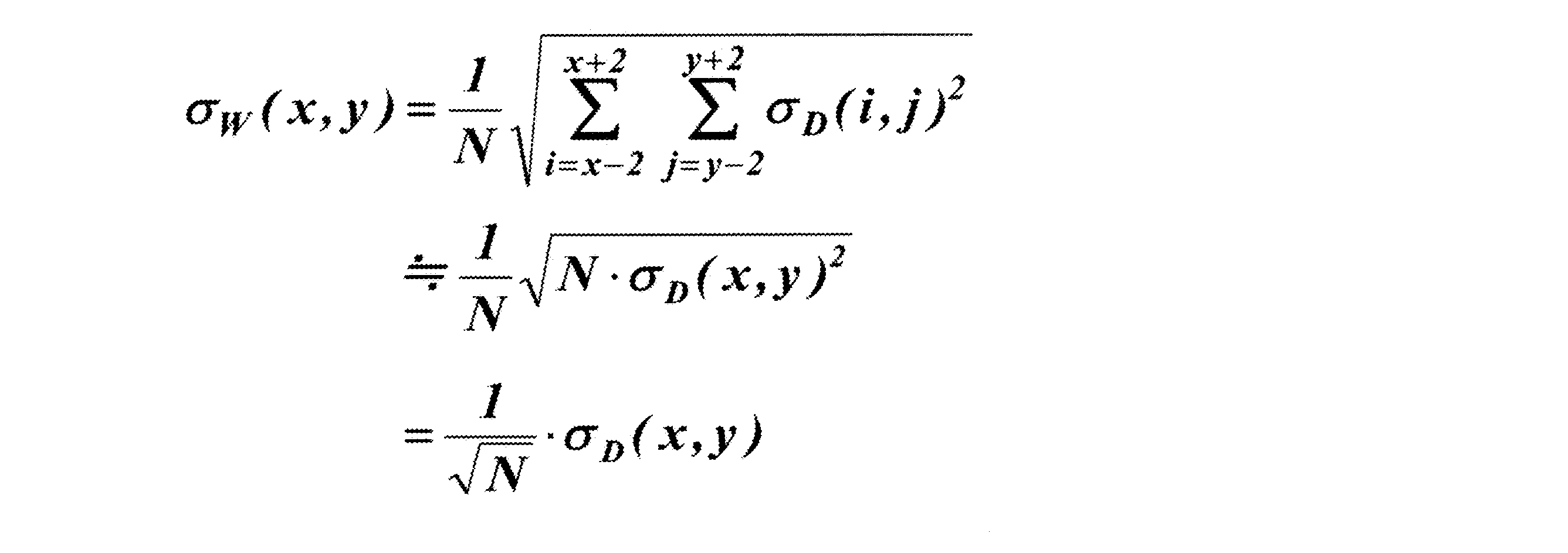
となり、σW(x,y)は、σD(x,y)の値の1/√Nとなる。N=25の場合は、1/√N=1/5であるから、温度補償変数W(x,y)は、時間的ゆらぎの分布の広がり(標準偏差)が、ダーク読取値D(x,y)にくらべて1/5の分布となる。すなわち、図8に示すように、広がりが狭い(標準偏差が小さい)分布となり、要件4)を満足する。
極端な例として、画素位置(x-2,y-2)~(x+2,y+2)の内、注目画素である(x,y)以外の(N?1)の画素位置におけるダーク読取値時間的ゆらぎの標準偏差値が、注目画素位置におけるダーク読取値D(x,y)の時間的ゆらぎの標準偏差値σD(x,y)に対して、N倍の大きさを持ったと仮定しても、N>2であれば、

となり、
σW(x,y)<σD(x,y)
が成立する。
σW(x,y)<σD(x,y)
が成立する。
N=25の場合、
SQRT[{1+(N-1)・N}/N2]
=SQRT{(1+24×25)/(25×25)}
≒0.981
となるから、
σW(x,y)≒0.981・σD(x,y)<σD(x,y)
通常、σD(x?2,y?2)~σD(x+2,y+2)のそれぞれの値は異なるが、平均を取るとσD(x,y)にほぼ等しい値を取ることから、上記方法は要件4)を満足すると言って良い。
SQRT[{1+(N-1)・N}/N2]
=SQRT{(1+24×25)/(25×25)}
≒0.981
となるから、
σW(x,y)≒0.981・σD(x,y)<σD(x,y)
通常、σD(x?2,y?2)~σD(x+2,y+2)のそれぞれの値は異なるが、平均を取るとσD(x,y)にほぼ等しい値を取ることから、上記方法は要件4)を満足すると言って良い。
温度補償変数としての空間的平均値W(x,y)の分布は、当該一の放射線検出素子(x,y)を中心とする正方領域内の複数の放射線検出素子14(以下、所定の領域Rに属する放射線検出素子14という意味で放射線検出素子14Rと表記する。)の数が多くなればなるほど、すなわちNの値が大きい程、温度補償変数としての空間的平均値W(x,y)の時間的ゆらぎの標準偏差σW(x,y)が小さくなる。これは、すなわち、σW(x,y)が十分に小さい値を取るとき、
W(x,y)≒μW(x,y) …(6)
と近似できることを意味している。
W(x,y)≒μW(x,y) …(6)
と近似できることを意味している。
すなわち、放射線画像撮影の直前又は直後に行われる1回のダーク読取で放射線検出素子14Rから出力されるダーク読取値D(x-2,y-2)~D(x+2,y+2)(以下、所定の領域Rに属する放射線検出素子14Rから出力されるダーク読取値という意味でダーク読取値DRと表記する。)は、図7に例示したように各時間的ゆらぎの分布内でその時間的ゆらぎの平均値μD(x-2,y-2)~μD(x+2,y+2)を中心としてゆらぐが、上記(3)式に従って算出される空間的平均値(温度補償変数)W(x,y)は、空間的平均値(温度補償変数)W(x,y)の分布の時間的平均値μW(x,y)にほぼ等しい値が算出される。
従って、当該一の放射線検出素子(x,y)を含む各放射線検出素子14Rから出力されるダーク読取値DRの時間的ゆらぎの分布の平均値μDや標準偏差σDが異なるとしても(図7参照)、それらの空間的平均値(温度補償変数)W(x,y)を算出すれば、各放射線検出素子14Rから出力された各ダーク読取値DRの時間的ゆらぎが有効に相殺されて数値の変動が非常に小さくなり、時間的ゆらぎの分布の平均値μW(x,y)にほぼ等しい空間的平均値(温度補償変数)W(x,y)を算出することができる。
言い換えれば、複数のダーク読取を実施しなければ求められない時間的ゆらぎの平均値を、1回のダーク読取で得られたダーク読取値D(x,y)の空間的平均値W(x,y)で、少ない誤差をもって代用できるということである。
ここで、一の放射線検出素子(x,y)について温度補償変数W(x,y)を算出する際の当該一の放射線検出素子(x,y)以外の放射線検出素子(x´,y´)の選択の仕方について説明する。
放射線検出素子(x,y)では、通常、放射線検出素子(x,y)や、この信号値を読み出すための読み出し回路の素子の温度が低いと当該放射線検出素子(x,y)から出力されるダーク読取値D(x,y)は小さな値となり、放射線検出素子(x,y)の温度Tが上昇するにつれて、出力されるダーク読取値D(x,y)の値も大きくなっていくことが知られている。そのため、例えば、図7に示したような各放射線検出素子(x,y)から出力されるダーク読取値D(x,y)の時間的ゆらぎの分布の平均値μD(x,y)も、温度が高くなると、同図のグラフ上で右方向にシフトしていく。
また、例えば放射線画像検出器1の電源がONされるとセンサパネル部4の温度が次第に上昇していくが、センサパネル部4上の各放射線検出素子(x,y)や読み出し回路の素子の温度変動は一様ではなく、例えば、周囲に多数の放射線検出素子(x´,y´)が存在するセンサパネル部4の中央部分の放射線検出素子(x,y)と、センサパネル部4の周縁部分の放射線検出素子(x,y)とでは、温度の変動の仕方が異なるし、読み出し回路を構成する読み出しICが異なれば、温度の変動の仕方が異なる。また、同じ読み出しIC内であっても、増幅回路17が異なれば、温度の変動の仕方が異なる。
このような状況において、一の放射線検出素子(x,y)について空間的平均値(温度補償変数)W(x,y)を算出する際の当該一の放射線検出素子(x,y)以外の放射線検出素子(x´,y´)として、例えばセンサパネル部4上で当該一の放射線検出素子(x,y)から遠く離れた放射線検出素子(x´,y´)を選ぶと、その温度変動が当該一の放射線検出素子(x,y)の温度変動と異なることが予測される。
そのため、例えば、図7に示したような各放射線検出素子(x´,y´)から出力されるダーク読取値D(x´,y´)の時間的ゆらぎの分布の温度による左右方向へのシフトの度合が、当該一の放射線検出素子(x,y)のダーク読取値D(x,y)の時間的ゆらぎの分布のシフトの度合と異なるものとなり、グラフ上の相対的な位置がそれぞれの画素位置の温度に依存して変動する。
このように、温度によって放射線検出素子(x,y)のダーク読取値D(x,y)の時間的ゆらぎの分布と他の放射線検出素子(x´,y´)の時間的ゆらぎの分布とのグラフ上の位置が、それぞれの画素位置の温度に依存して相対的にずれてしまうと、図9に示すように、それらの空間的平均値(温度補償変数)W(x,y)の分布はブロードになり、図8に示したような標準偏差σW(x,y)が小さい分布が得られなくなる。そのため、上記(3)式に従って算出される空間的平均値(温度補償変数)W(x,y)が、空間的平均値(温度補償変数)W(x,y)の時間的平均値μW(x,y)にほぼ等しい値となるという有益な効果を活用することができなくなってしまう。
そこで、本手法では、放射線画像撮影の直前又は直後に行われる1回のダーク読取の結果から一の放射線検出素子(x,y)について空間的平均値(温度補償変数)W(x,y)を算出するための当該一の放射線検出素子(x,y)以外の放射線検出素子(x´,y´)として、当該一の放射線検出素子(x,y)と同じように温度変動する放射線検出素子(x´,y´)が予め選択されて、当該一の放射線検出素子(x,y)に予め対応付けるようになっている。
その際、センサパネル部4上の全ての放射線検出素子(x,y)について同じ選択の仕方とされる必要はなく、放射線検出素子ごとに選択の仕方が異なってもよい。また、選択の仕方としては、例えば上記のように当該一の放射線検出素子(x,y)を中心とするn×nの正方領域内に存在する複数の放射線検出素子(x,y)Rを用いることが可能であるが、後述する図16A~図16Cや図19C、図19Dに示すように、正方領域は必ずしも当該一の放射線検出素子(x,y)が中心に存在するように設定されなくてもよい。
また、正方領域のサイズは、本実施例では5×5や7×7の例を用いたが(7×7の例は後述する図24~図26の説明文を参照)、このサイズに限定するものではない。1×1よりも大きいサイズであれば、2×2や3×3であっても良いし、9×9もしくはそれ以上のサイズであっても良い。また、正方領域の代わりに長方形状の領域を設定したり、不定形状の領域とすることも可能である。
さらに、当該一の放射線検出素子(x,y)以外の放射線検出素子(x´,y´)は当該一の放射線検出素子(x,y)と同じように温度変動する放射線検出素子であればよく、上記のような当該一の放射線検出素子(x,y)を含む空間的に連続する領域内に存在する放射線検出素子(x,y)Rでなく、センサパネル部4上に点在する放射線検出素子(x,y)であってもよい。なお、これらの同一の温度特性を示す検出素子群は、工場検査等において、予め把握することができる。また、施設設置後にも再設定することが可能である。
次に、上記の温度補償変数として使用する空間的平均値W(x,y)と当該一の放射線検出素子(x,y)のオフセット補正値O(x,y)の真値との関係について説明する。
放射線画像撮影の直前又は直後に1回だけ行われるダーク読取では、図10に示したように、一の放射線検出素子(x,y)からは、時間的なゆらぎを含む1個のダーク読取値D(x,y)しか得られず、オフセット補正値O(x,y)の真値は分からない。また、当該一の放射線検出素子(x,y)に対応付けられた放射線検出素子(x-2,y-2)~(x+2,y+2)から出力される1個ずつの各ダーク読取値D(x-2,y-2)~D(x+2,y+2)も時間的なゆらぎを含むものであり、それらに基づいて直接的に当該一の放射線検出素子(x,y)のオフセット補正値O(x,y)の真値を得ることはできない。
そこで、本手法では、以下で詳しく説明するように、過去の(当回の被写体の放射線画像撮影以前に行われた)キャリブレーション時にダーク読取を複数回行って当該一の放射線検出素子(x,y)自身から出力されたダーク読取値d(x,y)を得ておき、まず、一の放射線検出素子(x,y)から出力された複数回分のダーク読取値d(x,y)の時間的平均値δ(x,y)を算出する。
また、温度補償変数として、過去のキャリブレーション時の各回のダーク読取で、当該一の放射線検出素子(x,y)を中心とする前記正方領域内の複数の放射線検出素子(x,y)から出力されるダーク読取値dの空間的平均値(以下、上記の放射線画像撮影の直前や直後に行われる1回のダーク読取で得られる温度補償変数としての空間的平均値W(x,y)と区別するためにキャリブレーション時に得られる温度補償変数としての空間的平均値をw(x,y)と表す。)を算出し、さらに各回の温度補償変数としての空間的平均値w(x,y)の複数回分の時間的平均値ω(x,y)を算出する。
そして、上記の当該一の放射線検出素子(x,y)自身のダーク読取値d(x,y)の時間的平均値δ(x,y)と、温度補償変数としての空間的平均値w(x,y)の時間的平均値ω(x,y)と、今回の放射線画像撮影の直前又は直後に行われた1回のダーク読取で得られる、温度補償変数としての空間的平均値W(x,y)とを用いて、当該一の放射線検出素子(x,y)のオフセット補正値O(x,y)を算出するようになっている。
なお、本発明でキャリブレーションという場合、前述したような定期的に(例えば毎月)行われるゲイン補正値及びオフセット補正値の両方を更新するためのキャリブレーションだけでなく、ゲイン補正値に比べ、比較的温度変動が大きいオフセット補正値のみを対象とし、必要に応じて実行されるオフセットキャリブレーションも含まれる。
すなわち、本発明では、キャリブレーションとは、放射線画像検出器1の工場出荷時、施設への導入時、或いは放射線が曝射されていない待機時に、必要に応じて、ダーク読取値D(x,y)を含む実写画像データF(x,y)を補正するためのデータの全部又は一部を予め取得して作成するための作業をいい、上記のように定期的に行われるキャリブレーションよりも広い概念である。
従って、施設への導入後のキャリブレーションも、定期的なキャリブレーションよりも短い周期で(例えば毎日)行われる場合もある。また、1回のキャリブレーションやオフセットキャリブレーションでは、通常、複数回のダーク読取が行われる。
なお、あまりに古いデータを用いて時間的平均値δ(x,y)や温度補償変数としての空間的平均値w(x,y)、その時間的平均値ω(x,y)を算出するとそれらの値の信頼性が低下するため、それらの値の算出の元となるダーク読取値d(x,y)は、現在から所定回数前までのダーク読取で得られた値や、最新の(すなわち前回の)キャリブレーションやオフセットキャリブレーションで行われた複数回のダーク読取で得られた値を用いることが好ましい。
また、ダーク読取値d(x,y)から時間的平均値δ(x,y)等を算出する処理は、放射線画像検出器1で行ってもよく、或いは放射線画像検出器1からコンソール31(図28参照)等の外部の装置にダーク読取値d(x,y)を送信して外部装置で行うように構成することも可能である。
さて、上記の過去の複数回のダーク読取で得られた当該一の放射線検出素子(x,y)自身の各ダーク読取値d(x,y)の時間的平均値δ(x,y)は、下記(7)式に従って算出される。なお、下記(7)式で、Mは時間的平均値δ(x,y)等の算出に用いられるダーク読取値dm(x,y)の数、すなわち前記所定回数を表す。

図11に示すように、m回目(m=1~M)のダーク読取で当該一の放射線検出素子(x,y)からダーク読取値dm(x,y)が出力され、それらの値をヒストグラムにまとめて表すと、図12に示すように、時間的平均値δ(x,y)を中心とし標準偏差σd(x,y)とする正規分布状に分布する。この分布は、ダーク読取値dm(x,y)の時間的ゆらぎを表している。
また、過去のキャリブレーション時のm回目(m=1~M)のダーク読取で、当該一の放射線検出素子(x,y)を中心とする前記正方領域内の複数の放射線検出素子(x,y)Rから出力される各ダーク読取値dm(x,y)の空間的平均値wm(x,y)は、上記(3)式と同様の下記(8)式に従って算出される。なお、この場合、(8)式中のNも25(=5×5)である。

そして、各回の空間的平均値wm(x,y)のM回分の時間的平均値ω(x,y)は、下記(9)式に従って算出される。

図11に示すように、m回目(m=1~M)のダーク読取でそれぞれ空間的平均値wm(x,y)が算出され、それらの値をヒストグラムにまとめて表すと、図12に示すように、時間的平均値ω(x,y)を中心とし、標準偏差σw(x,y)の正規分布状に分布する。
なお、上記(9)式に(8)式と(7)式を代入して変形すると、

となることから分かるように、過去のキャリブレーション時のM回のダーク読取での各放射線検出素子(x,y)についての時間的平均値δ(x,y)が算出されれば、各回ごとにそれぞれ空間的平均値wm(x,y)を算出しなくても、各放射線検出素子(x,y)ごとの時間的平均値δ(x,y)を用いてダーク読取値dm(x,y)の空間的平均値wm(x,y)のM回分の時間的平均値ω(x,y)を算出することができる。
ここで、過去のキャリブレーション時の複数回のダーク読取で当該一の放射線検出素子(x,y)から出力されたダーク読取値d(x,y)の時間的平均値δ(x,y)と、温度補償変数としての空間的平均値w(x,y)の時間的平均値ω(x,y)と、今回の放射線画像撮影の直前又は直後に行われた1回のダーク読取で得られる温度補償変数としての空間的平均値W(x,y)と、当該一の放射線検出素子(x,y)のオフセット補正値O(x,y)の真値との関係について考察する。
キャリブレーションは、一般的に、患者撮影を行わない始業準備中、又は、終業準備中に行われることが多く、キャリブレーション時のダーク読取は、通常、予め設定された同一の温度T0の条件下で行われると見做すことができる。従って、過去のキャリブレーション時のダーク読取で得られる当該一の放射線検出素子(x,y)に関する時間的平均値δ(x,y)及び温度補償変数としての空間的平均値w(x,y)の時間的平均値ω(x,y)は、上記温度T0における値である。
一方、放射線画像撮影が行われる際の放射線検出素子(x,y)やセンサパネル部4上の当該放射線検出素子(x,y)の近傍の温度Tは、図13に示すように、必ずしもキャリブレーション時の温度T0ではない。
特に、放射線画像検出器1では、電源ONの状態でも、放射線画像撮影に使用されない場合には、電力の消費を抑えるために自動的又は手動の操作で電源消費状態がスリープモードとされるようになっているものも多く、図13に示すように、撮影可能モードでは放射線検出素子(x,y)等の温度Tが上昇し、スリープモード(図中のSの部分参照)ではセンサパネル部4への通電がされなくなるため、放射線検出素子(x,y)等の温度Tが低下する。
また、前述したように、放射線検出素子(x,y)では、通常、放射線検出素子(x,y)等の温度Tが低いと出力されるダーク読取値D(x,y)は小さな値となり、放射線検出素子(x,y)等の温度Tが上昇するにつれて出力されるダーク読取値D(x,y)の値も大きくなる。
そのため、図14に示すように、今回の放射線画像撮影の直前又は直後に行われた1回のダーク読取で一の放射線検出素子(x,y)から出力されるダーク読取値D(x,y)について推定される時間的ゆらぎの分布の中心値(平均値)や、当該一の放射線検出素子(x,y)に対応付けられた放射線検出素子(x,y)Rから出力されるダーク読取値DRの平均値である温度補償変数としての空間的平均値W(x,y)について推定される時間的ゆらぎの分布も、温度Tによって大きくなったり小さくなったりする。
すなわち、図14中のダーク読取値D(x,y)の分布や、温度補償変数としての空間的平均値W(x,y)の分布が、温度Tによって、図14中の横軸上を左右に変動する。一般には、温度Tが上昇すると、分布は横軸上を右側にシフトする傾向にあり、温度Tが下降すると、分布は横軸上を左側にシフトする傾向にある。なお、今回の放射線画像撮影の直前や直後に行われた1回のダーク読取で一の放射線検出素子(x,y)から出力されるダーク読取値D(x,y)等のゆらぎの分布はあくまで推定されるものであるため、図14では、破線で表示されている。
しかし、前述したように、その場合でも、当該一の放射線検出素子(x,y)を含む放射線検出素子(x´,y´)Rは同じように温度変動する。そのため、当該一の放射線検出素子(x,y)から出力されるダーク読取値D(x,y)について推定されるゆらぎの分布の図14のグラフ上の位置と、当該一の放射線検出素子(x,y)に対応付けられた放射線検出素子(x,y)Rから出力されるダーク読取値DRの平均値である温度補償変数としての空間的平均値W(x,y)について推定される時間的ゆらぎの分布のグラフ上の位置との相対的な位置関係(すなわち、それぞれの分布の平均値の距離)は温度が変動しても変わらないはずである。
ところで、もし今回の放射線画像撮影が温度T0の環境下で行われた場合、図14に示したダーク読取値D(x,y)について推定される時間的ゆらぎの分布の平均値μD(x,y)や、温度補償変数としての空間的平均値W(x,y)について推定される時間的ゆらぎの分布の平均値μW(x,y)は、図12に示した過去のキャリブレーション時の複数回のダーク読取で得られた複数のダーク読取値dm(x,y)の時間的ゆらぎの分布の平均値δ(x,y)や、当該一の放射線検出素子(x,y)を含む放射線検出素子14Rから出力される各ダーク読取値dm(x,y)の空間的平均値wm(x,y)の時間的ゆらぎの分布の平均値ω(x,y)にほぼ等しくなる。
また、上記のダーク読取値D(x,y)の時間的ゆらぎの分布の平均値μD(x,y)と温度補償変数としての空間的平均値W(x,y)の時間的ゆらぎの分布の平均値μW(x,y)との相対的な位置関係は上記のように、温度Tが変化しても変わらないため、各分布の平均値の差分、すなわちダーク読取値D(x,y)の時間的ゆらぎの分布の平均値μD(x,y)と温度補償変数としての空間的平均値W(x,y)の時間的ゆらぎの分布の平均値μW(x,y)との差分も、温度Tが変化しても変わらない。
そのため、今回の放射線画像撮影の直前又は直後に行われた1回のダーク読取で得られる当該一の放射線検出素子(x,y)のダーク読取値D(x,y)の分布の時間的平均値μD(x,y)と、温度補償変数としての空間的平均値W(x,y)の分布の時間的平均値μW(x,y)との差分をε(x,y)と置くと(図14参照)、
ε(x,y)=μD(x,y)-μW(x,y) …(11)
は、温度Tにかかわらず、図12に示した過去のキャリブレーション時の複数回のダーク読取で得られた複数のダーク読取値dm(x,y)の分布の時間的平均値δ(x,y)と、当該一の放射線検出素子(x,y)を含む放射線検出素子14Rから出力される各ダーク読取値dm(x,y)の空間的平均値wm(x,y)の分布の時間的平均値ω(x,y)との差分、
δ(x,y)-ω(x,y)
に等しくなる。
ε(x,y)=μD(x,y)-μW(x,y) …(11)
は、温度Tにかかわらず、図12に示した過去のキャリブレーション時の複数回のダーク読取で得られた複数のダーク読取値dm(x,y)の分布の時間的平均値δ(x,y)と、当該一の放射線検出素子(x,y)を含む放射線検出素子14Rから出力される各ダーク読取値dm(x,y)の空間的平均値wm(x,y)の分布の時間的平均値ω(x,y)との差分、
δ(x,y)-ω(x,y)
に等しくなる。
すなわち、
ε(x,y)=μD(x,y)-μW(x,y)
=δ(x,y)-ω(x,y) …(12)
が成立する。
ε(x,y)=μD(x,y)-μW(x,y)
=δ(x,y)-ω(x,y) …(12)
が成立する。
(12)式は、
μD(x,y)=ε(x,y)+μW(x,y) …(13)
これは、キャリブレーション時にあらかじめ算出できる変数、すなわち、ε(x,y)=δ(x,y)-ω(x,y)の値が分かっていれば、後は、μW(x,y)さえ分かれば、μD(x,y)を推定することができることを表している。
μD(x,y)=ε(x,y)+μW(x,y) …(13)
これは、キャリブレーション時にあらかじめ算出できる変数、すなわち、ε(x,y)=δ(x,y)-ω(x,y)の値が分かっていれば、後は、μW(x,y)さえ分かれば、μD(x,y)を推定することができることを表している。
ここで、前述したように、(6)式から
W(x,y)≒μW(x,y) …(6)
これを(13)式に代入すると、
μD(x,y)≒ε(x,y)+W(x,y) …(14)
の関係が得られる。
W(x,y)≒μW(x,y) …(6)
これを(13)式に代入すると、
μD(x,y)≒ε(x,y)+W(x,y) …(14)
の関係が得られる。
これは、キャリブレーション時にあらかじめ算出できる変数、すなわち、ε(x,y)=δ(x,y)-ω(x,y)の値が分かっていれば、後は、放射線画像撮影時に取得される1つのダーク画像から算出される温度補償変数W(x,y)さえ計算できれば、μD(x,y)を推定することができることを表している。
そして、前述した従来の場合と同様に、ダーク読取値D(x,y)について推定される時間的ゆらぎの分布の平均値μD(x,y)は、まさに当該放射線検出素子(x,y)のオフセット補正値O(x,y)の真値とみなすことができるから、結局、上記(14)式は、
O(x,y)≒ε(x,y)+W(x,y) …(15)
と書き換えることができる。
O(x,y)≒ε(x,y)+W(x,y) …(15)
と書き換えることができる。
これは、キャリブレーション時にあらかじめ算出できる変数、すなわち、ε(x,y)=δ(x,y)-ω(x,y)の値が分かっていれば、後は、放射線画像撮影時に取得される1つのダーク画像から算出される温度補償変数W(x,y)さえ計算できれば、O(x,y)、すなわちオフセット補正値の真値を推定することができることを表している。言い換えれば、キャリブレーション時にあらかじめ算出できる変数、すなわち、ε(x,y)=δ(x,y)-ω(x,y)の値が分かっていれば、放射線画像撮影時の放射線検出素子や電気回路などの各素子がその後どのように温度変化していても、たった1回のダーク画像における各画素位置毎の温度補償変数W(x,y)を計算すれば、放射線画像撮影時の放射線検出素子や電気回路などの各素子の温度状態における理想的なオフセット補正値O(x,y)が求められることを表している。
そこで、本手法では、
O(x,y)=ε(x,y)+W(x,y) …(16)
(ただし、ε(x,y)=δ(x,y)-ω(x,y))
に従って放射線検出素子(x,y)のオフセット補正値O(x,y)を算出するようになっている。
O(x,y)=ε(x,y)+W(x,y) …(16)
(ただし、ε(x,y)=δ(x,y)-ω(x,y))
に従って放射線検出素子(x,y)のオフセット補正値O(x,y)を算出するようになっている。
これにより、前述した課題を解決するための骨格となる手法が提案できた。
ところで、これまでの説明では、キャリブレーションを行った時の放射線画像検出器1内の各素子の温度は一定と見なして来たが、キヤリブレーション実施時、ダーク画像の取得数(上述のMの値)が大きくなると、キャリブレーション中にも放射線画像検出器1内の各素子の温度が変動してしまう。
上記(7)式~(10)式からも明白なように、Mの値が大きいほど、dm(x,y)、wm(x,y)の時間的なゆらぎが相殺され、(16)式の精度を左右する、ω(x,y)やδ(x,y)の精度が向上するが、Mの値が大きいほど、ω(x,y)やδ(x,y)の値は温度変動の影響を受けやすくなることを意味している。
そこで、この問題に対しても、これまで説明してきた温度補正の考え方を適応する。
(12)式に(7)式、(9)式を代入すると、
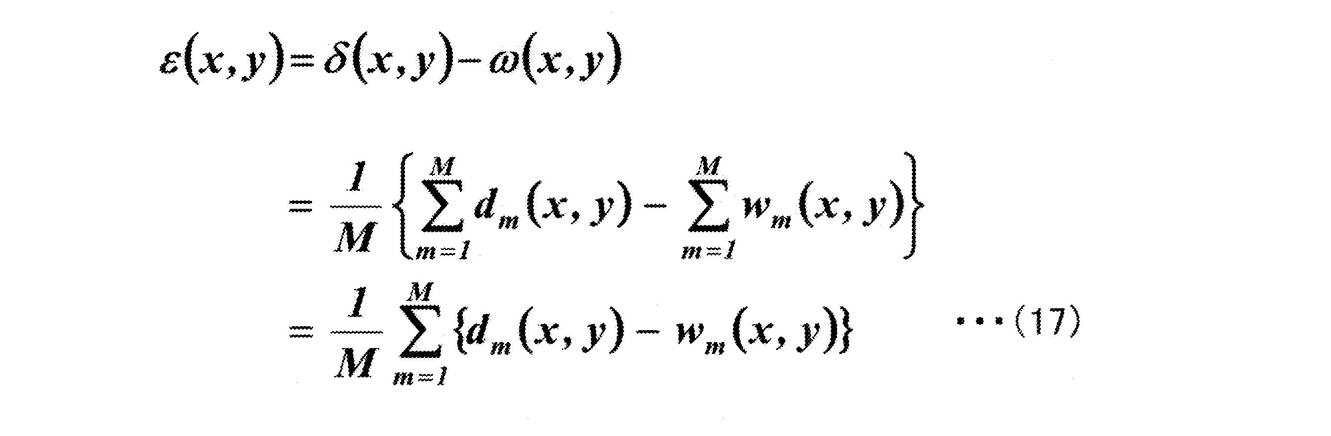
ここで、
λm(x,y)=dm(x,y)-wm(x,y) …(18)
とおくと、

λm(x,y)=dm(x,y)-wm(x,y) …(18)
とおくと、
ここで、λm(x,y)は、キャリブレーション時のダーク読取値dm(x,y)の温度変化を温度補償変数wm(x,y)によって温度補正された、温度補正済みダーク読取値λm(x,y)と考えることができる。
キャリブレーション時に放射線画像検出器1内の各素子の温度が変動してしまうと図15に示すように、dm(x,y)の分布は非常にブロードな分布となり、従って、上記(7)式で求められるdm(x,y)の時間的平均値δ(x,y)は、正しい値を示せなくなる。
そこで、一般的にキャリブレーション時にダーク読取を複数回実施し、その平均値を求める場合(従来は、この方法でオフセット補正値を直接求めることは前述した通りである)、直接dm(x,y)の平均値を計算するのではなく、上述のように、温度補正済みダーク読取値λm(x,y)の平均値(時間的平均値)であるε(x,y)を求めるようにすれば、温度変動が補正された正確なダーク読取の時間的平均値を求めることができるはずである。すなわち、ε(x,y)は温度補正済みダーク読取の時間的平均値と呼ぶことが可能である。
温度補正済みダーク読取値λm(x,y)や、温度補正済みダーク読取の時間的平均値ε(x,y)は、キャリブレーション時、さらには、放射線画像撮影時においても、ダーク読取を複数回実施し、その平均(時間的平均)を取る作業全てに適応することができる。また、時間的平均回数であるMの値が大きくとも、温度変動の影響を受けにくくすることができる。
また、キャリブレーション時にゲイン補正値G(x,y)を求める際にも、同様な温度補償を適応することが可能である。ゲイン補正値G(x,y)を求める際にも、あらかじめ定めておいた所定の放射線量で、被写体を置かない状態での放射線画像データを取得し、これにオフセット補正を施してゲイン補正値G(x,y)を計算するため、この際に取得する放射線画像データを、本手法の実写画像データF(x,y)と見なせば、本手法と同様の温度補正のかかったゲイン補正データG(x,y)を得ることができる。また、ゲイン補正値G(x,y)を求める際に使用されるオフセット補正値に対しても、同様に前述の温度補正を行うことが好ましい。これにより、精度の高いゲイン補正値G(x,y)を求めることができ、結果として、SN比の高い良好な画像データを得ることが可能となる。
本手法において、キャリブレーション時のM回のダーク読取で放射線検出素子(x,y)から出力された各ダーク読取値dm(x,y)の分布(図12参照)においては、時間的平均値δ(x,y)が算出されるが、さらに、分布の標準偏差σd(x,y)を算出し、
dm(x,y)-δ(x,y) …(20)
dm(x,y)/σd(x,y) …(21)
或いは、
(dm(x,y)-δ(x,y))/σd(x,y) …(22)
等の演算を行って各ダーク読取値dm(x,y)を正規化し、正規化された各ダーク読取値に基づいて上記の処理を構成することも可能である。
dm(x,y)-δ(x,y) …(20)
dm(x,y)/σd(x,y) …(21)
或いは、
(dm(x,y)-δ(x,y))/σd(x,y) …(22)
等の演算を行って各ダーク読取値dm(x,y)を正規化し、正規化された各ダーク読取値に基づいて上記の処理を構成することも可能である。
[放射線検出素子に予め対応付ける他の放射線検出素子の選択方法の例]
前述したように、一の放射線検出素子(x,y)について温度補償変数としての空間的平均値W(x,y)を算出するために当該一の放射線検出素子(x,y)に予め対応付ける他の放射線検出素子(x´,y´)については、当該一の放射線検出素子(x,y)と同じように温度変動するものであればよく、それらの選択の仕方としては、上記のように種々の手法があり得る。ここでは、放射線画像検出器1の実際的な構成に即した選択の仕方の一例について説明する。
前述したように、一の放射線検出素子(x,y)について温度補償変数としての空間的平均値W(x,y)を算出するために当該一の放射線検出素子(x,y)に予め対応付ける他の放射線検出素子(x´,y´)については、当該一の放射線検出素子(x,y)と同じように温度変動するものであればよく、それらの選択の仕方としては、上記のように種々の手法があり得る。ここでは、放射線画像検出器1の実際的な構成に即した選択の仕方の一例について説明する。
例えば、図6では、放射線画像検出器1のセンサパネル部4上で一の放射線検出素子(x,y)の周囲の行方向や列方向に十分な数の他の放射線検出素子(x´,y´)がある場合に、当該一の放射線検出素子(x,y)を中心として例えば5×5の正方領域内に存在する他の放射線検出素子(x-2,y-2)~(x+2,y+2)を選択する場合を示した。しかし、当該一の放射線検出素子(x,y)がセンサパネル部4の周縁部分にある場合には、このように例えば5×5の正方領域の中心に当該一の放射線検出素子(x,y)を位置させることができない場合もある。
従って、そのような場合には、例えば図16A~図16Cに示すように、図中で濃く着色されて表される当該一の放射線検出素子(x,y)の位置などを選択すれば良い。
なお、この場合、キャリブレーション時のダーク読取における空間的平均値wm(x,y)の算出やそれらの時間的平均値ω(x,y)の算出においても、当該放射線検出素子(x,y)についての領域Rは同じ要領で設定される。また、図16A~図16Cにおいて、格子状に表される各放射線検出素子の上方及び左方に記載されている数字は、それぞれ各放射線検出素子(x,y)の行方向及び列方向の位置を表す数字であり、左方の座標(x,y)は当該放射線検出素子(x,y)の座標を表すものである。
一方、各放射線検出素子(x,y)から電気信号を読み出し増幅するための読み出し回路9(図2参照)は、図17に示すように、通常、行方向に128画素や256画素ずつの放射線検出素子(x,y)ごとに1個ずつの読み出しIC91、92、…が接続されており、それが必要な数だけ並設されて構成されている。そして、読み出し回路9側の読み出しIC91、92、…ごとの温度特性やノイズ特性等が必ずしも同一ではないため、各放射線検出素子(x,y)のオフセット補正値O(x,y)が読み出しIC91、92、…ごとに異なる場合がある。
そのため、図18に示すように、放射線検出素子(x,y)のオフセット補正値O(x,y)を算出するために設定される領域Rに属する各放射線検出素子から電気信号を読み出す読み出しICが、隣接する読み出しIC91、92で別々に読み出される場合、その領域Rに属する各放射線検出素子(x,y)については温度補償変数W(x,y)やω(x,y)の値が誤差を持ってしまい、オフセット補正値O(x,y)を良好に算出できない場合がある。
そこで、このような場合には、例えば図19C、図19Dに示すように、読み出しIC91に接続されている放射線検出素子(x,y)と読み出しIC92に接続されている放射線検出素子(x,y)とを分けて考える。そして、読み出しIC91、92の境界Lの近傍に存在する放射線検出素子(x,y)を、上記のセンサパネル部4の周縁部分にある場合と同様に扱うことで、一の放射線検出素子(x,y)に予め対応付けられる複数の放射線検出素子を同一の読み出しIC91に接続される放射線検出素子の中から選択するように構成することが可能となる。
なお、図19A、図19Bには、図6等に示した通常の仕方で一の放射線検出素子(x,y)に予め対応付けられる複数の放射線検出素子が選択される場合が示されている。
[欠陥画素判定方法や異常画素判定方法等の特徴]
以下、本発明に係る欠陥画素判定方法や異常画素判定方法等の特徴について説明する。
以下、本発明に係る欠陥画素判定方法や異常画素判定方法等の特徴について説明する。
まず、欠陥画素は、製造後の出荷検査や、定期的なキャリブレーション時に放射線照射を伴う検査を実施することで検出され、検出された欠陥画素の画素位置が欠陥画素マップに登録し、個々の放射線画像検出器と対応付けて運用、管理されることは前述した通りである。
欠陥画素の例として、定常的に大きな画素値を出力する画素(例えば、信号値が常に飽和レベルまで達している画素)や、もしくは定常的に小さな画素値しか出力しない画素(例えば、常に信号値がゼロレベルの値しか出力しない画素)、また、常に一定の信号値しか出力しない画素(放射線を照射しても出力する画素値が変化しない画素)については、容易に判別することが可能であるため、このような欠陥画素については、既に判別されて欠陥画素マップに登録されているものとする。
ここで解決しようとしているのは、ある確率で異常な信号値を出力する異常な画素についてであり、これらの異常な画素を放射線を照射せずとも精度良く検出し、欠陥画素であるか否かを判定する方法、もしくは、異常な画素を欠陥画素マップに登録する方法、もしくは異常な画素を欠陥画素マップに登録せずに異常画素として適切に処理する方法、もしくは、放射線を照射した画像データ中の異常画素について対処する方法についてである。
そのため、本発明の主たる方法では、キャリブレーション時や放射線画像撮影の前後に取得するダーク読取値(放射線照射を必要としない読取信号)を使用して自動的に或いはユーザーの指示に基づいて欠陥画素判定や異常画素判定を行う。また、欠陥画素や異常画素を判別する際に、放射線画像検出器内の各素子の温度変動を考慮した欠陥画素を判別方法についても説明を行う。また、放射線を照射して得られた画像データの中から異常画素を検出し適切に対処する方法についても説明を行う。
まず、本発明で解決したい欠陥画素と異常画素についての説明を行う。(1)式に示したように、最終的な画像データFO(x,y)を得るには、実写画像データF(x,y)からオフセット補正値O(x,y)を差し引き、その差分にゲイン補正値G(x,y)を乗算する。
FO(x,y)=(F(x,y)-O(x,y))×G(x,y) …(1)
FO(x,y)=(F(x,y)-O(x,y))×G(x,y) …(1)
従って、実写画像データF(x,y)が正常な画素値を有していても、オフセット補正値O(x,y)やゲイン補正値G(x,y)に異常があれば、その演算結果である最終的な画像データFO(x,y)は異常値を示すため、これは異常な画素(本来補正すべき画素)ということになる。
また、オフセット補正値O(x,y)やゲイン補正値G(x,y)が正常であっても、実写画像データF(x,y)の値が異常であれば、その演算結果である最終的な画像データFO(x,y)は異常値を示すため、これも異常な画素(本来補正すべき画素)ということになる。
ある確率でオフセット補正値O(x,y)、ゲイン補正値G(x,y)、実写画像データF(x,y)で異常画素値を出力する画素位置(x,y)は、その異常値の強度(どれくらい異常かを示す指針)や異常値を出力する頻度に応じて分類され、許容できない、もしくは許容すべきでないと判断された異常な画素は、欠陥画素として欠陥画素マップに登録を行う。
また、突発的に異常値を出力する画素であっても、その異常値の強度(どれくらい異常かを示す指針)や異常値を出力する頻度が許容されるレベルと判断される場合は、異常画素として欠陥画素と同様の処理(補正処理など)を実施するが、欠陥画素として欠陥画素マップに登録しないことも許容する。もちろん、異常画素を全て欠陥画素として欠陥画素マップに登録しても良い。
ここで、ゲイン補正値G(x,y)については、キャリブレーション時に放射線を照射して算出するものであるが、オフセット補正値O(x,y)については、放射線を照射せずに算出できるパラメータである。
本発明者らは、このオフセット補正値の算出に使用するダーク読取値D(x,y)もしくはダーク読取値dm(x,y)に着目し、ある確率で発生する異常画素をダーク読取値D(x,y)もしくはダーク読取値dm(x,y)から見出し、判別し、欠陥画素や異常画素として処理する(場合によっては異常画素を欠陥画素として欠陥画素マップに登録する)方法を見出した。また、放射線画像データ中の異常画素についても検出し、適切に処理する方法についても見出した。
[欠陥画素判定方法及び欠陥画素判定プログラム]
以下、まず、本発明に係る欠陥画素判定方法及び欠陥画素判定プログラムの実施の形態について、図面を参照して説明する。ただし、本発明は以下の図示例のものに限定されるものではない。
以下、まず、本発明に係る欠陥画素判定方法及び欠陥画素判定プログラムの実施の形態について、図面を参照して説明する。ただし、本発明は以下の図示例のものに限定されるものではない。
前述した図5等に示したように、同じ温度Tの環境下にあったとしても、放射線画像検出器1の一の放射線検出素子(x,y)から出力されるダーク読取値D(x,y)にはゆらぎ(ばらつき)が生じ、ゆらぎの分布は平均値μ(x,y)を中心に標準偏差σ(x,y)を有する正規分布状の分布となる。
しかし、放射線検出素子(x,y)によっては、分布の平均値μ(x,y)が他の放射線検出素子(x´,y´)から出力されるダーク読取値D(x´,y´)の分布の平均値μ(x´,y´)から大きくかけ離れていたり、或いはゆらぎが非常に大きい場合、すなわち分布の標準偏差σ(x,y)が他の放射線検出素子(x´,y´)から出力されるダーク読取値D(x´,y´)の分布の標準偏差σ(x´,y´)に比べて非常に大きいような場合がある。
そのため、そのような放射線検出素子(x,y)では、最終的に得られる画像データFO(x,y)の安定性も悪くなり、欠陥画素と見なすことができる程の異常な値となってしまう場合がある。以下、このように、欠陥画素と見なすことができる放射線検出素子(x,y)を欠陥画素(xs,ys)と表す。
また、ダーク読取値D(x,y)の標準偏差σ(x,y)は正常な範囲に入るものの、時折異常な値を出力する画素が存在する。このような画素については、ダーク読取値D(x,y)の標準偏差σ(x,y)のみに注目していても検出することはできない。このように、ダーク読取値D(x,y)の標準偏差σ(x,y)は正常な範囲に入るものの、時折異常な値を出力する画素も、許容範囲を越えるものは異常画素と見なす。
そこで、本発明に係る欠陥画素判定方法及び欠陥画素判定プログラムでは、放射線検出素子(x,y)がある確率で異常画素となる場合、その発生確率や異常度合いから、欠陥画素(xs,ys)に登録するか否かを判定するようになっている。特に、本発明に係る欠陥画素判定プログラムでは、前述した放射線画像検出器1のコンピュータである制御手段6や、後述する欠陥画素判定システム30のコンピュータである欠陥画素判定装置(すなわち後述するコンソール31やサーバ手段39)に、この欠陥画素判定機能、すなわち以下に詳しく説明する欠陥画素判定機能を実現させるようになっているが、その一部の処理、もしくは全ての処理を放射線画像検出器1やコンソール31(又はサーバ手段39)の中で実施するようにしても良いことは言うまでもない。
前述したように、本発明では、過去のキャリブレーション時に複数回(M回)行われたダーク読取において放射線検出素子(x,y)自身から出力されたダーク読取値dm(x,y)の複数回分(M回分)のデータが、各放射線検出素子(x,y)ごとに蓄積される。そして、それらのダーク読取値dm(x,y)をヒストグラムにまとめて表すと、図12に示したように、各放射線検出素子(x,y)ごとにダーク読取値dm(x,y)の時間的ゆらぎの分布の時間的平均値δ(x,y)と標準偏差σd(x,y)等の時間的統計値を算出することができる。
そこで、本発明では、このように、過去のキャリブレーション時に複数回行われたダーク読取において得られた、一の放射線検出素子(x,y)から出力されたダーク読取値dm(x,y)の値そのもの、もしくはダーク読取値dm(x,y)の時間的ゆらぎの分布における時間的平均値δ(x,y)や標準偏差σd(x,y)等の時間的統計値に基づいて、下記の各判定手法に従って、当該一の放射線検出素子(x,y)が欠陥画素か否かを判定するようになっている。
[判定手法1]
まず、時間的統計値として、一の放射線検出素子(x,y)から出力されたダーク読取値dm(x,y)の時間的ゆらぎの分布における標準偏差σd(x,y)に着目し、標準偏差σd(x,y)が予め設定された閾値σdthよりも大きい場合に、当該一の放射線検出素子(x,y)を欠陥画素(xs,ys)として判定し、登録するように構成することが可能である。
まず、時間的統計値として、一の放射線検出素子(x,y)から出力されたダーク読取値dm(x,y)の時間的ゆらぎの分布における標準偏差σd(x,y)に着目し、標準偏差σd(x,y)が予め設定された閾値σdthよりも大きい場合に、当該一の放射線検出素子(x,y)を欠陥画素(xs,ys)として判定し、登録するように構成することが可能である。
ダーク読取値dm(x,y)の時間的ゆらぎの分布における標準偏差σd(x,y)が大きいということは、ダーク読取値dm(x,y)がある確率で異常な値を出力する可能性が大きいことを示しているので、予め設定された閾値σdthよりも大きい場合に欠陥画素(xs,ys)として判定し、欠陥画素マップに登録することで本発明が課題として認識している問題を解決することができる。
すなわち、過去のキャリブレーション時に複数回行われたダーク読取において得られた、一の放射線検出素子(x,y)から出力されたダーク読取値dm(x,y)のゆらぎの分布における標準偏差σd(x,y)が閾値σdth以下、すなわち、
σd(x,y)≦σdth …(23)
であれば、当該一の放射線検出素子(x,y)のダーク読取値dm(x,y)のゆらぎ(ばらつき)は許容範囲内であり、正常画素であると判定される。この場合、当該一の放射線検出素子(x,y)は、欠陥画素としては登録されない。
σd(x,y)≦σdth …(23)
であれば、当該一の放射線検出素子(x,y)のダーク読取値dm(x,y)のゆらぎ(ばらつき)は許容範囲内であり、正常画素であると判定される。この場合、当該一の放射線検出素子(x,y)は、欠陥画素としては登録されない。
しかし、図20の右側の正規分布に示すように、一の放射線検出素子(x,y)から出力されたダーク読取値dm(x,y)の時間的ゆらぎの分布における標準偏差σd(x,y)が、図20の左側の正規分布に示す通常の放射線検出素子(x,y)から出力されるダーク読取値dm(x,y)の時間的ゆらぎの分布における平均的な標準偏差σd(x,y)よりも大きく、かつ閾値σdthを越える場合、すなわち、
σd(x,y)>σdth …(24)
が成り立つ場合には、当該一の放射線検出素子(x,y)のダーク読取値dm(x,y)の時間的ゆらぎ(ばらつき)は許容範囲を越えるものであり、欠陥画素であると判定される。そして、この場合、当該一の放射線検出素子(x,y)は、欠陥画素(xs,ys)として欠陥画素マップに登録される。
σd(x,y)>σdth …(24)
が成り立つ場合には、当該一の放射線検出素子(x,y)のダーク読取値dm(x,y)の時間的ゆらぎ(ばらつき)は許容範囲を越えるものであり、欠陥画素であると判定される。そして、この場合、当該一の放射線検出素子(x,y)は、欠陥画素(xs,ys)として欠陥画素マップに登録される。
上記の閾値σdthは、例えば、放射線検出素子(x,y)から出力されるダーク読取値dm(x,y)の時間的ゆらぎの分布における平均的な標準偏差σd(x,y)の3倍~10倍程度の値に設定されることが好ましいが、この値には限定されない。
なお、標準偏差σd(x,y)の代わりに分散σd2(x,y)を用い、分散σd2(x,y)に閾値を設定して、上記と同様に処理するように構成することも可能である。
[判定手法2]
また、時間的統計値として、一の放射線検出素子(x,y)から出力されたダーク読取値dm(x,y)の時間的ゆらぎの分布における時間的平均値δ(x,y)に着目し、時間的平均値δ(x,y)が予め設定された閾値δth1(以下、第1閾値δth1という。)よりも大きいか、或いは前記閾値δth1よりも小さい値に設定された別の閾値δth2(以下、第2閾値δth2という。)よりも小さい場合に、当該一の放射線検出素子(x,y)は何からの欠陥を有しているとのと見なせるため、これを欠陥画素(xs,ys)として判定し、登録するように構成することが可能である。
また、時間的統計値として、一の放射線検出素子(x,y)から出力されたダーク読取値dm(x,y)の時間的ゆらぎの分布における時間的平均値δ(x,y)に着目し、時間的平均値δ(x,y)が予め設定された閾値δth1(以下、第1閾値δth1という。)よりも大きいか、或いは前記閾値δth1よりも小さい値に設定された別の閾値δth2(以下、第2閾値δth2という。)よりも小さい場合に、当該一の放射線検出素子(x,y)は何からの欠陥を有しているとのと見なせるため、これを欠陥画素(xs,ys)として判定し、登録するように構成することが可能である。
ダーク読取値dm(x,y)の時間的ゆらぎの分布における時間的平均値δ(x,y)が大きすぎる場合、もしくは小さすぎる場合は、ダーク読取値dm(x,y)が今後もある確率で異常な値を出力する可能性が大きいことを示しているので、予め設定された第1閾値δth1よりも大きいか、或いは第2閾値δthよりも小さい場合に欠陥画素(xs,ys)として判定し、欠陥画素マップに登録することで本発明が課題として認識している問題を解決することができる。
すなわち、過去のキャリブレーション時に複数回(M回)行われたダーク読取において得られた、一の放射線検出素子(x,y)から出力されたダーク読取値dm(x,y)の時間的ゆらぎの分布における時間的平均値δ(x,y)が、他の放射線検出素子(x*,y*)と同様に、第2閾値δth2以上第1閾値δth1以下、すなわち、
δth2≦δ(x,y)≦δth1 …(25)
であれば、当該一の放射線検出素子(x,y)から出力されるダーク読取値dm(x,y)の大きさは、他の放射線検出素子(x*,y*)から出力されるダーク読取値dm(x*,y*)の大きさとさほど大きくは変わらず許容範囲内であり、正常画素であると判定される。この場合、当該一の放射線検出素子(x,y)は、欠陥画素としては登録されない。
δth2≦δ(x,y)≦δth1 …(25)
であれば、当該一の放射線検出素子(x,y)から出力されるダーク読取値dm(x,y)の大きさは、他の放射線検出素子(x*,y*)から出力されるダーク読取値dm(x*,y*)の大きさとさほど大きくは変わらず許容範囲内であり、正常画素であると判定される。この場合、当該一の放射線検出素子(x,y)は、欠陥画素としては登録されない。
しかし、図21に示すように一の放射線検出素子(x,y)から出力されたダーク読取値dm(x,y)の時間的ゆらぎの分布における時間的平均値δ(x,y)が大きく、閾値δth1より大きい場合、すなわち、
δ(x,y)>δth1 …(26)
が成り立つ場合、或いは、一の放射線検出素子(x,y)から出力されたダーク読取値dm(x,y)の時間的ゆらぎの分布における時間的平均値δ(x,y)が小さく、閾値δth2より小さい場合、すなわち、
δ(x,y)<δth2 …(27)
が成り立つ場合には、当該一の放射線検出素子(x,y)から出力されるダーク読取値dm(x,y)の大きさは、他の放射線検出素子(x*,y*)から出力されるダーク読取値dm(x*,y*)の大きさとの違いが大きく許容範囲を越えるものであり、欠陥画素であると判定される。そして、この場合、当該一の放射線検出素子(x,y)は、欠陥画素(xs,ys)として欠陥画素マップに登録される。
δ(x,y)>δth1 …(26)
が成り立つ場合、或いは、一の放射線検出素子(x,y)から出力されたダーク読取値dm(x,y)の時間的ゆらぎの分布における時間的平均値δ(x,y)が小さく、閾値δth2より小さい場合、すなわち、
δ(x,y)<δth2 …(27)
が成り立つ場合には、当該一の放射線検出素子(x,y)から出力されるダーク読取値dm(x,y)の大きさは、他の放射線検出素子(x*,y*)から出力されるダーク読取値dm(x*,y*)の大きさとの違いが大きく許容範囲を越えるものであり、欠陥画素であると判定される。そして、この場合、当該一の放射線検出素子(x,y)は、欠陥画素(xs,ys)として欠陥画素マップに登録される。
[判定手法3]
また、時間的統計値として、一の放射線検出素子(x,y)から出力されたダーク読取値dm(x,y)の値の大きさそのものに着目し、ダーク読取値dm(x,y)の値が予め設定された閾値dmthよりも大きい場合に、当該一の放射線検出素子(x,y)は何からの欠陥を有しているとのと見なせるため、これを欠陥画素(xs,ys)として判定し、登録するように構成することが可能である。
また、時間的統計値として、一の放射線検出素子(x,y)から出力されたダーク読取値dm(x,y)の値の大きさそのものに着目し、ダーク読取値dm(x,y)の値が予め設定された閾値dmthよりも大きい場合に、当該一の放射線検出素子(x,y)は何からの欠陥を有しているとのと見なせるため、これを欠陥画素(xs,ys)として判定し、登録するように構成することが可能である。
ダーク読取値dm(x,y)そのものの値が大きすぎるということは、今後もある確率でダーク読取値dm(x,y)が異常な値を出力する可能性が大きいことを示しているので、予め設定された閾値dmthよりも大きい場合に欠陥画素(xs,ys)として判定し、欠陥画素マップに登録することで本発明が課題として認識している問題を解決することができる。
すなわち、過去のキャリブレーション時に複数回(M回)行われたダーク読取において得られた、一の放射線検出素子(x,y)から出力されたダーク読取値dm(x,y)の値が、他の放射線検出素子(x*,y*)と同様に、閾値dmth以下、すなわち、
dm(x,y)≦dmth …(28)
であれば、当該一の放射線検出素子(x,y)から出力されるダーク読取値dm(x,y)の大きさは、他の放射線検出素子(x*,y*)から出力されるダーク読取値dm(x*,y*)の大きさとさほど大きくは変わらず許容範囲内であり、正常画素であると判定される。この場合、当該一の放射線検出素子(x,y)は、欠陥画素としては登録されない。
dm(x,y)≦dmth …(28)
であれば、当該一の放射線検出素子(x,y)から出力されるダーク読取値dm(x,y)の大きさは、他の放射線検出素子(x*,y*)から出力されるダーク読取値dm(x*,y*)の大きさとさほど大きくは変わらず許容範囲内であり、正常画素であると判定される。この場合、当該一の放射線検出素子(x,y)は、欠陥画素としては登録されない。
しかし、一の放射線検出素子(x,y)から出力されたダーク読取値dm(x,y)の値が閾値dmthより大きい場合、すなわち、
dm(x,y)>dmth …(29)
が成り立つ場合には、当該一の放射線検出素子(x,y)から出力されるダーク読取値dm(x,y)の大きさは、他の放射線検出素子(x*,y*)から出力されるダーク読取値dm(x*,y*)の大きさとの違いが大きく許容範囲を越えるものであり、欠陥画素であると判定される。そして、この場合、当該一の放射線検出素子(x,y)は、欠陥画素(xs,ys)として欠陥画素マップに登録される。
dm(x,y)>dmth …(29)
が成り立つ場合には、当該一の放射線検出素子(x,y)から出力されるダーク読取値dm(x,y)の大きさは、他の放射線検出素子(x*,y*)から出力されるダーク読取値dm(x*,y*)の大きさとの違いが大きく許容範囲を越えるものであり、欠陥画素であると判定される。そして、この場合、当該一の放射線検出素子(x,y)は、欠陥画素(xs,ys)として欠陥画素マップに登録される。
さて、上記[判定手法1]~[判定手法3]では、過去のキャリブレーション時に複数回(M回)行われたダーク読取において放射線検出素子(x,y)自身から出力されたダーク読取値dm(x,y)のみを用いて、その時間的統計値から当該一の放射線検出素子(x,y)が欠陥画素か否かを判定するように構成する場合を説明した。すなわち、複数回(M回)行われたダーク読取期間中、放射線検出素子(x,y)から出力される信号値は温度変化の影響を受けていない、もしくは、信号値の温度変化による影響は無視できるほど小さいと見なされた。
しかしながら、複数回(M回)のダーク読取期間中に、放射線検出素子(x,y)から出力される信号値は温度変化の影響を受けている場合、この温度変化を補償する方が、精度の良い判定を行うことができる。
そこで、前述した放射線画像検出器の各放射線検出素子のオフセット補正値手法におけるキャリブレーション時の温度補償の考え方を用いて、一の放射線検出素子(x,y)自身から出力されるダーク読取値dm(x,y)や、当該一の放射線検出素子(x,y)と同じように温度変動し、当該一の放射線検出素子(x,y)に予め対応付けられた複数の放射線画像検出素子(x´,y´)から出力される各ダーク読取値dm(x´,y´)の空間的平均値wm(x,y)等を用いて、当該一の放射線検出素子(x,y)が欠陥画素か否かを判定し、登録するように構成する方法について[判定手法4]~[判定手法6]で説明する。
この温度補償の考え方を取り入れることによって、欠陥画素の判定を行う際に、温度起因の誤差を除去することができるので、欠陥画素の判定を温度の影響を受けることなく精度良く実施することが可能となる。
[判定手法4]
ここで説明を行う判定手法は、上記[判定手法1]に温度補償の考え方を取り入れた手法である。まず、過去のキャリブレーション時に複数回(M回)行われたダーク読取において、各回のダーク読取ごとに、一の放射線検出素子(x,y)自身から出力されたダーク読取値dm(x,y)と、当該一の放射線検出素子(x,y)と同じように温度変動し当該一の放射線検出素子(x,y)に予め対応付けられた複数の放射線検出素子(x´,y´)から出力された各ダーク読取値dm(x´,y´)の空間的平均値wm(x,y)との、下記(30)式で表される差分em(x,y)を新たに定義する。すなわち、空間的平均値wm(x,y)をダーク読取値dm(x,y)の温度補償変数として使用する。
em(x,y)=dm(x,y)-wm(x,y) …(30)
ここで説明を行う判定手法は、上記[判定手法1]に温度補償の考え方を取り入れた手法である。まず、過去のキャリブレーション時に複数回(M回)行われたダーク読取において、各回のダーク読取ごとに、一の放射線検出素子(x,y)自身から出力されたダーク読取値dm(x,y)と、当該一の放射線検出素子(x,y)と同じように温度変動し当該一の放射線検出素子(x,y)に予め対応付けられた複数の放射線検出素子(x´,y´)から出力された各ダーク読取値dm(x´,y´)の空間的平均値wm(x,y)との、下記(30)式で表される差分em(x,y)を新たに定義する。すなわち、空間的平均値wm(x,y)をダーク読取値dm(x,y)の温度補償変数として使用する。
em(x,y)=dm(x,y)-wm(x,y) …(30)
なお、当該一の放射線検出素子(x,y)に予め対応付けられた複数の放射線検出素子(x´,y´)から出力された各ダーク読取値dm(x´,y´)の空間的平均値wm(x,y)は、当該一の放射線検出素子(x,y)が欠陥画素か否かを判定するために当該一の放射線検出素子(x,y)自身から出力されるダーク読取値dm(x,y)と対比して用いられるものであるから、空間的平均値wm(x,y)を算出する対象である複数の放射線検出素子(x´,y´)からの各ダーク読取値dm(x´,y´)の中に、当該一の放射線検出素子(x,y)から出力されたダーク読取値dm(x,y)は含めない方が好ましいという考え方と、空間的平均値wm(x,y)を算出する対象である複数の放射線検出素子(x´,y´)からの各ダーク読取値dm(x´,y´)の中に、当該一の放射線検出素子(x,y)から出力されたダーク読取値dm(x,y)を含めても良いという考え方がある。
本発明では、このいずれも許容するものであり、いずれか一方に限定するものではない。この考え方については、前述のオフセット補正値取得手法についても同様である。
また、当該一の放射線検出素子(x,y)に予め対応付けられ、当該一の放射線検出素子(x,y)と同じように温度変動する他の複数の放射線検出素子(x´,y´)の選択の仕方は、前述した通りである。
さて、このようにして、過去のキャリブレーション時に複数回(M回)行われたダーク読取の各回のダーク読取ごとに算出される差分em(x,y)の値をヒストグラムにまとめて表すと、当該一の放射線検出素子(x,y)が正常画素であれば、例えば図22に示すように、差分em(x,y)の時間的ゆらぎ(ばらつき)の分布は、平均的な標準偏差σe(x,y)を有する正規分布状の分布となる。
しかし、当該一の放射線検出素子(x,y)が欠陥画素(xs,ys)であれば、当該一の放射線検出素子(xs,ys)から出力されるダーク読取値dm(xs,ys)自体が正常画素の場合よりも格段に大きくゆらぐため、差分em(xs,ys)の時間的ゆらぎ(ばらつき)の分布は、例えば図23に示すように、大きな標準偏差σe(xs,ys)を有する正規分布状の分布となる。
そこで、上記の差分em(x,y)の時間的ゆらぎの分布における標準偏差σe(x,y)に着目し、標準偏差σe(x,y)が予め設定された閾値σethよりも大きい場合に、当該一の放射線検出素子(x,y)を欠陥画素(xs,ys)として判定し、登録するように構成することが可能である。
すなわち、過去のキャリブレーション時に複数回(M回)行われたダーク読取において、各回のダーク読取ごとに、一の放射線検出素子(x,y)自身から出力されたダーク読取値dm(x,y)と、当該一の放射線検出素子(x,y)に予め対応付けられた複数の放射線検出素子(x´,y´)から出力された各ダーク読取値dm(x´,y´)の空間的平均値wm(x,y)との差分em(x,y)を算出して、差分em(x,y)の時間的ゆらぎの分布における標準偏差σe(x,y)を時間的統計値として算出し、標準偏差σe(x,y)が予め設定された閾値σethよりも大きい場合、すなわち、
σe(x,y)>σeth …(31)
が成り立つ場合に、当該一の放射線検出素子(x,y)は欠陥画素であると判定される。そして、この場合、当該一の放射線検出素子(x,y)は、欠陥画素(xs,ys)として欠陥画素マップに登録される。
σe(x,y)>σeth …(31)
が成り立つ場合に、当該一の放射線検出素子(x,y)は欠陥画素であると判定される。そして、この場合、当該一の放射線検出素子(x,y)は、欠陥画素(xs,ys)として欠陥画素マップに登録される。
上記の閾値σethは、前述した閾値σdthの場合と同様に、例えば、差分em(x,y)の時間的ゆらぎの分布における平均的な標準偏差σe(x,y)の3倍~10倍程度の値に設定されることが好ましいが、この値には限定されない。また、標準偏差σe(x,y)の代わりに分散σe2(x,y)を用い、分散σe2(x,y)に閾値を設定して、上記と同様に処理するように構成することも可能である。
なお、差分em(x,y)は、(30)式に示したように、ダーク読取値dm(x,y)に対してwm(x,y)で温度補償を行った変数であるため、ダーク読取値dm(x,y)の温度変化による誤差が相殺されている。従って、差分em(x,y)の時間的ゆらぎの標準偏差σe(x,y)は、ダーク読取値dm(x,y)の時間的ゆらぎの標準偏差σd(x,y)に対して、
σe(x,y)≦σd(x,y) …(32)
なる関係が成立している。すなわち、差分em(x,y)のヒストグラムの分布の広がりは、ダーク読取値dm(x,y)のヒストグラムの分布の広がりに比べて同等以下になっている。これより、[判定手法4]は[判定手法1]に比べて、温度変化に対する誤差が少ない手法と言える。
σe(x,y)≦σd(x,y) …(32)
なる関係が成立している。すなわち、差分em(x,y)のヒストグラムの分布の広がりは、ダーク読取値dm(x,y)のヒストグラムの分布の広がりに比べて同等以下になっている。これより、[判定手法4]は[判定手法1]に比べて、温度変化に対する誤差が少ない手法と言える。
[判定手法5]
ここで説明を行う判定手法は、上記[判定手法2]に温度補償の考え方を取り入れた手法である。
ここで説明を行う判定手法は、上記[判定手法2]に温度補償の考え方を取り入れた手法である。
時間的統計値として、上記の差分εm(x,y)の時間的ゆらぎの分布における時間的平均値に着目する。なお、上記の図22及び図23に示したいずれの場合も差分em(x,y)の時間的ゆらぎの分布の時間的平均値は、前述の(12)式
ε(x,y)=δ(x,y)-ω(x,y) …(12)
で算出される温度補正済みダーク読取の時間的平均値ε(x,y)に計算上等しくなる。
ε(x,y)=δ(x,y)-ω(x,y) …(12)
で算出される温度補正済みダーク読取の時間的平均値ε(x,y)に計算上等しくなる。
そのため、この場合、温度補正済みダーク読取の時間的平均値ε(x,y)が、予め設定された閾値εth1(以下、第1閾値εth1という。)よりも大きいか、或いは前記閾値εth1よりも小さい値に設定された別の閾値εth2(以下、第2閾値εth2という。)よりも小さい場合に、当該一の放射線検出素子(x,y)を欠陥画素(xs,ys)として判定し、欠陥画素マップに登録するように構成する。
すなわち、過去のキャリブレーション時に複数回(M回)行われたダーク読取において得られた差分ε(x,y)が、第2閾値εth2以上第1閾値εth1以下、すなわち、
εth2≦ε(x,y)≦εth1 …(33)
であれば、当該一の放射線検出素子(x,y)から出力されるダーク読取値dm(x,y)の大きさは、他の放射線検出素子(x*,y*)から出力されるダーク読取値dm(x*,y*)の大きさとさほど大きくは変わらず、許容範囲内であり正常画素であると判定される。この場合、当該一の放射線検出素子(x,y)は、欠陥画素としては登録されない。
εth2≦ε(x,y)≦εth1 …(33)
であれば、当該一の放射線検出素子(x,y)から出力されるダーク読取値dm(x,y)の大きさは、他の放射線検出素子(x*,y*)から出力されるダーク読取値dm(x*,y*)の大きさとさほど大きくは変わらず、許容範囲内であり正常画素であると判定される。この場合、当該一の放射線検出素子(x,y)は、欠陥画素としては登録されない。
しかし、温度補正済みダーク読取の時間的平均値ε(x,y)が閾値εth1より大きい場合、すなわち、
ε(x,y)>εth1 …(34)
又は、温度補正済みダーク読取の時間的平均値ε(x,y)が閾値εth2より小さい場合、すなわち、
ε(x,y)<εth2 …(35)
が成り立つ場合には、当該一の放射線検出素子(x,y)から出力されるダーク読取値dm(x,y)の大きさは、他の放射線検出素子(x*,y*)から出力されるダーク読取値dm(x*,y*)の大きさとの違いが大きく許容範囲を越えるものであり、欠陥画素であると判定される。そして、この場合、当該一の放射線検出素子(x,y)は、欠陥画素(xs,ys)として欠陥画素マップに登録される。
ε(x,y)>εth1 …(34)
又は、温度補正済みダーク読取の時間的平均値ε(x,y)が閾値εth2より小さい場合、すなわち、
ε(x,y)<εth2 …(35)
が成り立つ場合には、当該一の放射線検出素子(x,y)から出力されるダーク読取値dm(x,y)の大きさは、他の放射線検出素子(x*,y*)から出力されるダーク読取値dm(x*,y*)の大きさとの違いが大きく許容範囲を越えるものであり、欠陥画素であると判定される。そして、この場合、当該一の放射線検出素子(x,y)は、欠陥画素(xs,ys)として欠陥画素マップに登録される。
なお、温度補正済みダーク読取の時間的平均値ε(x,y)は、(12)式に示すように、ダーク読取値dm(x,y)の時間的平均値δ(x,y)に対してω(x,y)で温度補償を行った変数であるため、ダーク読取値dm(x,y)の温度変化による誤差が相殺されている。これより、[判定手法5]は[判定手法2]に比べて、温度変化に対する誤差が少ない手法と言える。
[判定手法6]
ここで説明を行う判定手法は、上記[判定手法3]に温度補償の考え方を取り入れた手法である。すなわち、判定に用いる時間的統計値として、各ダーク読取値dm(x,y)の変わりに、(30)式で定義された、差分em(x,y)の絶対値である|em(x,y)|を使用する。
ここで説明を行う判定手法は、上記[判定手法3]に温度補償の考え方を取り入れた手法である。すなわち、判定に用いる時間的統計値として、各ダーク読取値dm(x,y)の変わりに、(30)式で定義された、差分em(x,y)の絶対値である|em(x,y)|を使用する。
差分em(x,y)の絶対値|em(x,y)|の値が予め設定された閾値emthよりも大きい場合に、当該一の放射線検出素子(x,y)は何からの欠陥を有しているとのと見なせるため、これを欠陥画素(xs,ys)として判定し、登録するように構成することが可能である。
すなわち、過去のキャリブレーション時に複数回(M回)行われたダーク読取において得られた、一の放射線検出素子(x,y)から出力されたダーク読取値dm(x,y)と空間的平均値wm(x,y)の差分em(x,y)の絶対値が、他の放射線検出素子(x*,y*)と同様に、閾値emth以下、すなわち、
|em(x,y)|≦emth …(36)
であれば、当該一の放射線検出素子(x,y)から出力されるダーク読取値dm(x,y)の大きさは、他の放射線検出素子(x*,y*)から出力されるダーク読取値dm(x*,y*)の大きさとさほど大きくは変わらず許容範囲内であり、正常画素であると判定される。この場合、当該一の放射線検出素子(x,y)は、欠陥画素としては登録されない。
|em(x,y)|≦emth …(36)
であれば、当該一の放射線検出素子(x,y)から出力されるダーク読取値dm(x,y)の大きさは、他の放射線検出素子(x*,y*)から出力されるダーク読取値dm(x*,y*)の大きさとさほど大きくは変わらず許容範囲内であり、正常画素であると判定される。この場合、当該一の放射線検出素子(x,y)は、欠陥画素としては登録されない。
しかし、一の放射線検出素子(x,y)について計算される差分em(x,y)の絶対値が閾値emthより大きい場合、すなわち、
|em(x,y)|>emth …(37)
が成り立つ場合には、当該一の放射線検出素子(x,y)から出力されるダーク読取値dm(x,y)の大きさは、他の放射線検出素子(x*,y*)から出力されるダーク読取値dm(x*,y*)の大きさとの違いが大きく許容範囲を越えるものであり、欠陥画素であると判定される。そして、この場合、当該一の放射線検出素子(x,y)は、欠陥画素(xs,ys)として欠陥画素マップに登録される。
|em(x,y)|>emth …(37)
が成り立つ場合には、当該一の放射線検出素子(x,y)から出力されるダーク読取値dm(x,y)の大きさは、他の放射線検出素子(x*,y*)から出力されるダーク読取値dm(x*,y*)の大きさとの違いが大きく許容範囲を越えるものであり、欠陥画素であると判定される。そして、この場合、当該一の放射線検出素子(x,y)は、欠陥画素(xs,ys)として欠陥画素マップに登録される。
なお、差分em(x,y)は、(30)式に示したように、ダーク読取値dm(x,y)に対してwm(x,y)で温度補償を行った変数であるため、ダーク読取値dm(x,y)の温度変化による誤差が相殺されている。これより、[判定手法6]は[判定手法1]に比べて、温度変化に対する誤差が少ない手法と言える。
また、上記[判定手法1]~[判定手法6]においては、予め定められた閾値を越えた画素を直ちに欠陥画素として登録するのではなく、例えば、その回数(頻度)によって、欠陥画素として登録するか否かを決定するようにしても良い。さらに、所定の間隔で閾値を複数設定しておき、その間隔ごとのヒストグラム(所定の区間に入る異常画素の個数)を算出して、その区間位置と、その区間での異常画素の発生頻度に応じて欠陥画素をとして登録するか否かを決定するようにしても良い。
以上のように、本実施形態に係る欠陥画素判定方法及び欠陥画素判定プログラムによれば、ダーク読取値dm(x,y)のゆらぎの分布において、例えば、標準偏差σd(x,y)が格段に大きかったり、ゆらぎの分布における時間的平均値δ(x,y)が異常な値であったり、ダーク読取値dm(x,y)そのものが異常な値となるような放射線検出素子(x,y)を的確に見出して、その放射線検出素子(x,y)を的確に欠陥画素であると判定して欠陥画素マップに登録することが可能となる。
そのため、そのような欠陥画素を予め登録しておくことで、オフセット補正値O(x,y)を算出したり、実写画像データF(x、y)を補正して最終的な画像データFO(x、y)を生成する際に、そのような欠陥画素の悪影響を的確に排除することが可能となり、最終的な画像データFO(x,y)のSN比を良好なものとすることが可能となる。
また、欠陥画素を予め登録しておくことで、その他の要因で欠陥画素として登録された欠陥画素群と同様に、例えば欠陥画素マップの形で一括して統一的に登録、管理することが可能となる。
さらに、前述したように、放射線検出素子(x,y)から出力されたダーク読取値dm(x,y)は温度変動によりその値が上下する。しかし、上記の[判定手法4]、[判定手法5]、[判定手法6]によれば、過去のキャリブレーション時の各回のダーク読取ごとに、一の放射線検出素子(x,y)自身から出力されたダーク読取値dm(x,y)と、当該一の放射線検出素子(x,y)に予め対応付けられた複数の放射線検出素子(x´,y´)から出力された各ダーク読取値dm(x´,y´)の空間的平均値wm(x,y)との差分εm(x,y)を算出し、それに基づいて当該一の放射線検出素子(x,y)が欠陥画素か否かを判定する。
そのため、差分εm(x,y)に着目することで、ダーク読取値dm(x,y)の温度変動による値の変動の影響が除去された状態で、放射線検出素子(x,y)が欠陥画素か否かを判定することが可能となり、温度に影響されない状態で、欠陥画素をより安定的に見出すことが可能となる。
なお、[判定手法1]~[判定手法3]もしくは[判定手法4]~[判定手法6]については、それぞれ単独で使用して欠陥画素を登録することができるが、[判定手法1]~[判定手法3]もしくは[判定手法4]~[判定手法6]の手法の組み合わせ、例えば、[判定手法1]と[判定手法3]もしくは[判定手法4]と[判定手法6]の組み合わせや、[判定手法1]、[判定手法2]、[判定手法3]もしくは[判定手法4]、[判定手法5]、[判定手法6]の組み合わせを用いることにより、さらに精度良く欠陥画素の登録を行うことができる。
また、放射線画像撮影ごとに、撮影の直前や直後のダーク読取値D(x,y)(ダーク読取値が複数ある場合は複数のダーク読取値Dm(x,y)の平均値)をオフセット補正値O(x,y)として使用する場合においては、放射線画像撮影の直前や直後のダーク読取値D(x,y)、もしくはダーク読取値Dm(x,y)、もしくはダーク読取値Dm(x,y)の平均値に対して、本発明の[判定手法3]もしくは[判定手法6]を使用して、ダーク読取値D(x,y)、もしくはダーク読取値Dm(x,y)、もしくはダーク読取値Dm(x,y)の平均値が異常値であるか否かを判定して、欠陥画素の判定、登録を行うことができる。
[異常画素判定方法及び異常画素判定プログラム]
上記の[判定手法1]~[判定手法6]においては、キャリブレーション時に複数回(M回)実施されるダーク読取や放射線画像撮影の直前又は直後に行われるダーク読取のダーク読取値を使用するため、Mの値を十分大きくすることで発生頻度を含めた統計的判断が可能である。そのため、欠陥画素として判定して良か否か或いは登録して良いか否かの判断ができた。
上記の[判定手法1]~[判定手法6]においては、キャリブレーション時に複数回(M回)実施されるダーク読取や放射線画像撮影の直前又は直後に行われるダーク読取のダーク読取値を使用するため、Mの値を十分大きくすることで発生頻度を含めた統計的判断が可能である。そのため、欠陥画素として判定して良か否か或いは登録して良いか否かの判断ができた。
しかしながら、放射線画像撮影の直前や直後のダーク読取値D(x,y)を使用する場合、キャリブレーション時のように必ずしも十分な数のダーク読取値D(x,y)を使用することができない場合があり(特に1回もしくは2回のダーク読取で対応する場合など)、認識された異常画素値が極めて稀に発生した突発的現象なのか、欠陥画素として登録して良い程に異常値が頻度高く出てくるものであるのかの判定が難しい場合がある。
そこで、本説明では、このような異常画素は直ちに欠陥画素として登録を行わずに、異常画素として一時的な対応を行う場合についても説明する。これら異常画素を欠陥画素として登録するか否かについては、後で説明を行う。
以下に、放射線画像撮影の直前や直後のダーク読取値D(x,y)に対して[判定手法6]を応用した場合の異常画素判定方法について説明を行う。
[判定手法7]
まず、ダーク読取値D(x,y)と空間的平均値W(x,y)の差分E(x,y)を以下のように定義する。
E(x,y)=D(x,y)-W(x,y) …(38)
まず、ダーク読取値D(x,y)と空間的平均値W(x,y)の差分E(x,y)を以下のように定義する。
E(x,y)=D(x,y)-W(x,y) …(38)
差分E(x,y)の絶対値を|E(x,y)|と表した時、差分E(x,y)の絶対値|E(x,y)|が予め設定された閾値Ethよりも大きい場合に、当該一の放射線検出素子(x,y)は何からの異常を有しているとのと見なせるため、これを異常画素として判定し、一時的に記憶しておく。
すなわち、一の放射線検出素子(x,y)から出力され放射線画像撮影の直前や直後のダーク読取値D(x,y)と空間的平均値W(x,y)の差分E(x,y)の絶対値|E(x,y)|が、他の放射線検出素子(x*,y*)と同様に、閾値Eth以下、すなわち、
|E(x,y)|≦Eth …(39)
であれば、当該一の放射線検出素子(x,y)から出力されるダーク読取値D(x,y)の大きさは、他の放射線検出素子(x*,y*)から出力されるダーク読取値D(x*,y*)の大きさとさほど大きくは変わらず許容範囲内であり、正常画素であると判定される。
|E(x,y)|≦Eth …(39)
であれば、当該一の放射線検出素子(x,y)から出力されるダーク読取値D(x,y)の大きさは、他の放射線検出素子(x*,y*)から出力されるダーク読取値D(x*,y*)の大きさとさほど大きくは変わらず許容範囲内であり、正常画素であると判定される。
しかし、一の放射線検出素子(x,y)について計算される差分E(x,y)の絶対値が閾値Ethより大きい場合、すなわち、
|E(x,y)|>Eth …(40)
が成り立つ場合には、当該一の放射線検出素子(x,y)から出力されるダーク読取値D(x,y)の大きさは、他の放射線検出素子(x*,y*)から出力されるダーク読取値D(x*,y*)の大きさとの違いが大きく許容範囲を越えるものであり、異常画素であると判定される。
|E(x,y)|>Eth …(40)
が成り立つ場合には、当該一の放射線検出素子(x,y)から出力されるダーク読取値D(x,y)の大きさは、他の放射線検出素子(x*,y*)から出力されるダーク読取値D(x*,y*)の大きさとの違いが大きく許容範囲を越えるものであり、異常画素であると判定される。
なお、差分E(x,y)は、(38)式に示したように、ダーク読取値D(x,y)に対してW(x,y)で温度補償を行った変数であるため、ダーク読取値D(x,y)の温度変化による誤差が相殺されている。
もしも異常画素と判定された場合は、その画素位置が欠陥画素マップに登録していなくとも、一時的に欠陥画素同等と見なし、欠陥画素と同様に、周囲の画素値を用いて補間処理により異常画素自体の異常値の補正を行う補正処理等を施すことによって、最終的な画像データFO(x,y)の中に異常画素が発生するのを防ぐことができる。
上記[判定手法7]で示した方法は、さらに、以下に示す[判定手法8]に発展させることができる。
[判定手法8]
まず、[判定手法7]と同様に、ダーク読取値D(x,y)と空間的平均値W(x,y)の差分E(x,y)を(38)式に従って計算する。
まず、[判定手法7]と同様に、ダーク読取値D(x,y)と空間的平均値W(x,y)の差分E(x,y)を(38)式に従って計算する。
次に、過去のキャリブレーション時に複数回(M回)行われたダーク読取において、(12)式に従って計算された、ダーク読取値dm(x,y)の分布の時間的平均値δ(x,y)とダーク読取値dm(x,y)の空間的平均値wm(x,y)の分布の時間的平均値ω(x,y)との差分ε(x,y)と、前記(38)式によって計算された差分E(x,y)との差分Λ(x,y)を(41)式に従って求める。
Λ(x,y)=ε(x,y)-E(x,y) …(41)
Λ(x,y)=ε(x,y)-E(x,y) …(41)
ここで、差分Λ(x,y)の絶対値を|Λ(x,y)|と表すと、この絶対値が予め設定された閾値Λthよりも大きい場合に、当該一の放射線検出素子(x,y)は何からの異常を有していると見なせるため、これを異常画素として判定し、一時的に記憶しておく。
すなわち、差分Λ(x,y)の絶対値が、他の放射線検出素子(x*,y*)と同様に、閾値Λth以下、すなわち、
|Λ(x,y)|≦Λth …(42)
であれば、当該一の放射線検出素子(x,y)から出力されるダーク読取値D(x,y)の大きさは、他の放射線検出素子(x*,y*)から出力されるダーク読取値D(x*,y*)の大きさとさほど大きくは変わらず許容範囲内であり、正常画素であると判定される。
|Λ(x,y)|≦Λth …(42)
であれば、当該一の放射線検出素子(x,y)から出力されるダーク読取値D(x,y)の大きさは、他の放射線検出素子(x*,y*)から出力されるダーク読取値D(x*,y*)の大きさとさほど大きくは変わらず許容範囲内であり、正常画素であると判定される。
しかし、一の放射線検出素子(x,y)について計算される差分Λ(x,y)の絶対値が閾値Λthより大きい場合、すなわち、
|Λ(x,y)|>Λth …(43)
が成り立つ場合には、当該一の放射線検出素子(x,y)から出力されるダーク読取値D(x,y)の大きさは、他の放射線検出素子(x*,y*)から出力されるダーク読取値D(x*,y*)の大きさとの違いが大きく許容範囲を越えるものであり、異常画素であると判定される。
|Λ(x,y)|>Λth …(43)
が成り立つ場合には、当該一の放射線検出素子(x,y)から出力されるダーク読取値D(x,y)の大きさは、他の放射線検出素子(x*,y*)から出力されるダーク読取値D(x*,y*)の大きさとの違いが大きく許容範囲を越えるものであり、異常画素であると判定される。
なお、差分Λ(x,y)は、(41)式に示したように、共に温度補償を行った変数である差分ε(x,y)と差分E(x,y)どうしの演算であるため、ダーク読取値D(x,y)の温度変化による誤差が相殺されている。
もしも異常画素と判定された場合は、その画素位置が欠陥画素マップに登録していなくとも、一時的に欠陥画素同等と見なし、欠陥画素と同様に、周囲の画素値を用いて補間処理により異常画素自体の異常値の補正を行う補正処理等を施すことによって、最終的な画像データFO(x,y)の中に異常画素が発生するのを防ぐことができる。
なお、[判定手法7]、[判定手法8]で示した異常画素の取扱については、以下の選択肢1)~5)の方法のいずれかを採用することが可能である。
選択肢1)偶発的に発生した異常画素と見なし、欠陥画素としては登録しない。
選択肢2)欠陥画素(xs,ys)として、直ちに欠陥画素マップに登録する。
選択肢3)異常画素の値の大きさに応じて、欠陥画素として登録するか否かを決める。すなわち、異常画素の値が非常に大きい場合(別途定められた欠陥画素への登録を判定するための閾値を越えた場合)は、欠陥画素(xs,ys)として欠陥画素マップに登録する。
選択肢4)異常画素として、欠陥画素とは別に画素位置を記憶しておき、その後、同じ画素位置の信号値がある頻度で異常画素となれば、その時点で発生確率の判定を行い、予め定められた発生確率の閾値を越えた時点で欠陥画素(xs,ys)として欠陥画素マップに登録する。
選択肢5)上記、選択肢3)と選択肢4)を組み合わせて実施する。
選択肢2)欠陥画素(xs,ys)として、直ちに欠陥画素マップに登録する。
選択肢3)異常画素の値の大きさに応じて、欠陥画素として登録するか否かを決める。すなわち、異常画素の値が非常に大きい場合(別途定められた欠陥画素への登録を判定するための閾値を越えた場合)は、欠陥画素(xs,ys)として欠陥画素マップに登録する。
選択肢4)異常画素として、欠陥画素とは別に画素位置を記憶しておき、その後、同じ画素位置の信号値がある頻度で異常画素となれば、その時点で発生確率の判定を行い、予め定められた発生確率の閾値を越えた時点で欠陥画素(xs,ys)として欠陥画素マップに登録する。
選択肢5)上記、選択肢3)と選択肢4)を組み合わせて実施する。
上記[判定手法4]~[判定手法8]については、温度補償変数である空間的平均値wm(x,y)や空間的平均値W(x,y)、及びこれらの温度補償変数を使用して求められた新たな変数である差分ε(x,y)、差分em(x,y)、差分E(x,y)、絶対値|Λ(x,y)|などが使われている。ここで、空間的平均値wm(x,y)や空間的平均値W(x,y)の中に、欠陥画素として登録されていない突発的な異常画素が存在したならば、温度補償係数の値の精度が低下してしまう懸念がある。
しかしながら、温度補償係数の場合は、ダーク読取値(D(x,y)やDm(x,y)やdm(x,y))の注目画素位置(x,y)に対してその周辺のN個の画素値の空間的平均値であるため、仮にN個の周辺画素の中に欠陥画素として登録されていない突発的な異常画素が存在したとしても、その影響は1/Nに緩和されているので大きな問題とはならないが、別途手段を設けて突発的な異常画素を検出し、温度補償変数の計算に使用する画素から除外するようにしても良い。
さて、ここまでは、欠陥画素や異常画素をダーク読取値を用いて判別する方法について述べてきた。しかしながら、前述したように、良好な最終的な画像データFO(x,y)を得るには、オフセット補正値O(x,y)やゲイン補正値G(x,y)のみならず、実写画像データF(x,y)についても良好であること求められる。
すなわち、オフセット補正値O(x,y)やゲイン補正値G(x,y)に対して欠陥画素や異常画素の対処が適切になされていても、実写画像データF(x,y)の画素値の中に突発的な異常画素が含まれていれば、最終的な画像データFO(x,y)にも異常画素が認識されることになるため好ましくない。従って、実写画像データF(x,y)についても、欠陥画素補正だけでなく、突発的に発生する異常画素に対して適切な処置を施すことが好ましい。
しかしながら、実写画像データF(x,y)については、下記に示すような特徴があるため、これまで説明して来たダーク読取値ほど扱いが簡単ではない。
1)実写画像データF(x,y)は殆どの場合、1回しか放射線撮影されない実写画像データF(x,y)として扱う必要がある。同じ被写体に対して複数回撮影される場合もあるが、その場合、複数回の放射線画像撮影の間に被写体を動かしたり被写体の向きを変えたりするため、おのおのが独立した実写画像データF(x,y)であると考えなければならない。
2)実写画像データF(x,y)を取得するための放射線画像撮影とは、ゲイン補正データを取得するためのベタ画像撮影(ベタ画像撮影とは被写体を置かずに、一様な放射線を照射する撮影のこと)をのぞき、必ず被写体を置いての撮影となるため、実写画像データF(x,y)には被写体の画像が写り込んでいる。
しかも、前述したように、実写画像データF(x,y)は1回しか放射線撮影されない独立したデータであるため、実写画像データF(x,y)の値が被写体情報を正確に反映しているのか否かを客観的に判断することが難しい。例えば、同じ被写体に対して同条件での放射線画像撮影が複数回行われれば(複数回の撮影の間、被写体は動いていないと仮定する)、所定の画素位置(x,y)について複数回の画像データのばらつきを比較することにより、統計的な見地から被写体情報をほぼ正確に反映しているか否かを判断できる。
例えば、複数回の放射線画像撮影における画素位置(x,y)の信号値の平均値を計算し、その平均値からの各信号値のばらつきを測定した時、ばらつきが少なければ、それらの信号値は被写体情報をほぼ正確に反映していると判断できる。一方、複数回の放射線画像撮影における画素位置(x,y)の信号値の平均値に対して、ある信号値の値が平均値から大きく逸脱した値を有していれば、その信号値は被写体情報を正確に反映しておらず、ノイズ等の影響を受けた異常画素であると判断できる。
このように、同じ被写体に対して同条件での放射線画像撮影が複数回行われれば、統計的な見地から被写体情報をほぼ正確に反映しているか否かを判断できるが、実写画像データF(x,y)は1回しか放射線撮影されない独立したデータであるため、このような統計的判断をすることができない。
従って、各画素値に対して、本来どのような値であるべきか(各画素値のあるべき値、すなわち各画素値の真値)が分からない。例えば、ダーク読取値であれば、キャリブレーション時に取得した複数回のデータに対して今回のデータが正常であるか異常であるかは、上記のような統計的処理によって判断することができるが、1回しか放射線撮影されない実写画像データF(x,y)に対しては同様の判断を行う術がない。
このような課題の中で、実写画像データF(x,y)中に発生した突発的な異常画素を判別し、適切な処置を施す手法について以下に説明を行う。
[判定手法9]
まず、実写画像データF(x,y)の各画素値は、被写体の放射線吸収率によって様々に変化するが、それは画素サイズレベルのミクロの視点で見れば、非常になだらかに変化する信号値である(通常の画素サイズは100~200ミクロンの範疇で選択されることが多く、100ミクロン以下の選択はあっても200ミクロンを越える画素サイズの選択は行われない場合が多い)。特に特定画素だけが大きく変化するような画素は存在しないと言って良い。また、最も画素レベルに近いサイズを有する病変としては、乳房撮影における微小石灰化があるが、これは放射線を吸収する方向に作用するため、信号値が減衰する方向で信号値が変化する。
まず、実写画像データF(x,y)の各画素値は、被写体の放射線吸収率によって様々に変化するが、それは画素サイズレベルのミクロの視点で見れば、非常になだらかに変化する信号値である(通常の画素サイズは100~200ミクロンの範疇で選択されることが多く、100ミクロン以下の選択はあっても200ミクロンを越える画素サイズの選択は行われない場合が多い)。特に特定画素だけが大きく変化するような画素は存在しないと言って良い。また、最も画素レベルに近いサイズを有する病変としては、乳房撮影における微小石灰化があるが、これは放射線を吸収する方向に作用するため、信号値が減衰する方向で信号値が変化する。
ここで問題にしたい異常画素は、殆どが信号値が大きくなるように作用するため(信号値が小さくなるように作用する異常は既に欠陥画素として登録されている)、放射線を吸収する方向に作用する病変が異常画素と混同されることはない。
一方、信号値が大きくなるように作用する病変で、かつ画素レベルのサイズを持つものは存在しないため、独立した画素で周囲の画素に対して大きな値を持つものは突発的な異常画素と見なして問題ない。本発明ではこの特性を利用して、実写画像データF(x,y)の突発的な異常画素の判別を行う。
さらに突発的に発生する画素は常に孤立した1画素である。そもそも突発的に発生する異常画素は、発生頻度が低く(発生頻度が高いものは、既に欠陥画素として登録されている)、かつ、1枚のフラットパネルディテクタは通常5メガ画素前後の画素数を有するため、今回問題にしている突発的な異常画素が並んで、もしくはクラスター状の塊として発生する確率は天文学的に小さい。
従って、上述したように、今回課題として取り上げている突発的な異常画素は常に孤立した1画素として発生すると見なして良い。もちろん、隣り合って発生する場合や、クラスター状の塊として発生する場合を考慮しても良いことは言うまでもないが、以下の説明では、孤立した1画素として発生すると見なして説明を行う。
上記とまとめると、今回課題としている実写画像データF(x,y)の突発的な異常画素は以下の性質をもつものとして考えられる。
1)異常画素は必ず信号値が大きくなる(放射線が多く照射された画素のような挙動を示す)
2)異常画素は孤立した1点である。異常画素の周囲の画素は、欠陥画素として登録されている画素以外は必ず正常な画素である。
3)正常画素は、信号値が大きくなる方向にはなめらかに変化し、1画素単位で大きな画素変化を示さない。
2)異常画素は孤立した1点である。異常画素の周囲の画素は、欠陥画素として登録されている画素以外は必ず正常な画素である。
3)正常画素は、信号値が大きくなる方向にはなめらかに変化し、1画素単位で大きな画素変化を示さない。
上記突発的異常画素を判別する方法の1つの実施例を、前述した図6を使って以下に示す。
例えば複数の放射線検出素子(x,y)として当該一の放射線検出素子(x,y)すなわち、画素位置(x,y)を、実写画像データの注目画素位置とする。そして、画素位置(x,y)を中心とする5×5の正方領域内に存在する25の画素位置(x-2,y-2)~(x+2,y+2)を比較領域として定義し、この比較領域の信号値から、注目画素である画素位置(x,y)の信号値を除く24個の信号値の平均値をA(x,y)と表すと、

ここでLの値は、この場合24(=5×5?1)である。本例では、L=24とし、画素位置(x,y)中心とする5×5の正方領域を比較領域として説明を行うが、比較領域の選定方法はこれに限定するものでない。L=8(=3×3?1)として、画素位置(x,y)中心とする3×3の正方領域を比較領域としても良いし、例えば7×7もしくはそれ以上のサイズの正方領域を比較領域として採用しても本発明の効果を損なうものではない。また、比較領域として画素位置(x,y)囲む領域が選定されていれば、比較領域は必ずしも正方領域でなくとも良い。また、演算回数を減らすために、比較領域を画素位置(x,y)の上下、左右の4画素としたり、比較領域を画素位置(x,y)の上下もしくは左右の2画素としても良い。
次に、(45)式に従って、差分V(x,y)を計算する。
V(x,y)=F(x,y)-A(x,y) …(45)
V(x,y)=F(x,y)-A(x,y) …(45)
この差分V(x,y)が、予め設定された閾値Vth以下であれば、すなわち、
V(x,y)≦Vth …(46)
であれば、当該一の放射線検出素子から出力された実写画像データF(x,y)の値は変更せずにそのまま使用する。
V(x,y)≦Vth …(46)
であれば、当該一の放射線検出素子から出力された実写画像データF(x,y)の値は変更せずにそのまま使用する。
一方、差分V(x,y)が、予め設定された閾値Vthよりも大きい場合、すなわち、
V(x,y)>Vth …(47)
であれば、当該一の放射線検出素子から出力された実写画像データF(x,y)を異常画素と判定して、(49)式に定義される平均値B(x,y)で実写画像データF(x,y)の値を置き換える((48)式参照)。
F(x,y)←B(x,y) …(48)
V(x,y)>Vth …(47)
であれば、当該一の放射線検出素子から出力された実写画像データF(x,y)を異常画素と判定して、(49)式に定義される平均値B(x,y)で実写画像データF(x,y)の値を置き換える((48)式参照)。
F(x,y)←B(x,y) …(48)
ここで、画素位置(x,y)を中心とする3×3の正方領域内に存在する9つの画素位置(x-1,y-1)~(x+1,y+1)を計算領域として定義し、この計算領域の信号値から、注目画素である画素位置(x,y)の信号値を除く8個の信号値の平均値を平均値B(x,y)とする。

(49)式において、Pの値は、この場合8(=3×3?1)である。本例では、P=8とし、画素位置(x,y)中心とする3×3の正方領域を計算領域として説明を行うが、計算較領域の選定方法はこれに限定するものでない。P=24(=5×5?1)として、画素位置(x,y)中心とする5×5の正方領域を比較領域としても良いし、例えば7×7もしくはそれ以上のサイズの正方領域を比較領域として採用しても良い。また、計算領域として画素位置(x,y)囲む領域が選定されていれば、計算領域は必ずしも正方領域でなくとも良い。また、演算回数を減らすために、計算領域を画素位置(x,y)の上下、左右の4画素としたり、計算領域を画素位置(x,y)の上下もしくは左右の2画素としても良い。
また、ここでは、比較領域A(x,y)と計算領域B(x,y)を個別に定義したが(比較領域と計算領域は必ずしも一致している必要はない)、比較領域A(x,y)と計算領域B(x,y)を同一のものとして扱っても良い。なお、比較領域や計算領域の中に欠陥画素が存在した場合は、欠陥画素に隣接する正常画素を使用して平均値A(x,y)や平均値B(x,y)を計算すれば良い。
このように、実写画像データF(x,y)の中に突発的に異常画素に対する対応を行えば、最終的な画像データFO(x,y)の中に異常画素は発生することがなくなり、良好な診断画像を安定的に供給することが可能となる。なお、ここで検出された異常画素の取扱(欠陥画素として登録するか否か)については、上述の[判定手法8]の後に記述した選択肢1)~5)の方法のいずれかを採用することが可能である。
[判定手法10]
なお、上記では、実写画像データF(x,y)中の異常画素は必ず信号値が大きくなる(放射線が多く照射された画素のような挙動を示す)として説明を行ったが、異常画素が、信号値が小さくなる方向に変化する場合も考慮しても良い。すなわち、
なお、上記では、実写画像データF(x,y)中の異常画素は必ず信号値が大きくなる(放射線が多く照射された画素のような挙動を示す)として説明を行ったが、異常画素が、信号値が小さくなる方向に変化する場合も考慮しても良い。すなわち、
1)異常画素は必ず周囲の画素値に対して大きくなる方向、もしくは小さくなる方向に異常値を持つ。
2)異常画素は孤立した1点である。異常画素の周囲の画素は、欠陥画素として登録されている画素以外は必ず正常な画素である。
3)正常画素は、はなめらかに変化し、1画素単位で大きな画素変化を示さない。
として判断を行っても良い。
2)異常画素は孤立した1点である。異常画素の周囲の画素は、欠陥画素として登録されている画素以外は必ず正常な画素である。
3)正常画素は、はなめらかに変化し、1画素単位で大きな画素変化を示さない。
として判断を行っても良い。
すなわち、(45)式のV(x、y)に対する絶対値|V(x、y)|を定義し、この絶対値|V(x、y)|が、予め設定された閾値V´th以下であれば、すなわち、
|V(x、y)|≦V´th …(50)
であれば、当該一の放射線検出素子から出力された実写画像データF(x,y)の値は変更せずにそのまま使用する。
|V(x、y)|≦V´th …(50)
であれば、当該一の放射線検出素子から出力された実写画像データF(x,y)の値は変更せずにそのまま使用する。
一方、差分V(x,y)の絶対値|V(x、y)|が、予め設定された閾値V´thよりも大きい場合、すなわち、
|V(x、y)|>V´th …(51)
であれば、当該一の放射線検出素子から出力された実写画像データF(x,y)を異常画素と判定して、(49)式に定義される平均値B(x,y)で実写画像データF(x,y)の値を置き換えるようにしても良い((48)式参照)。以下、[判定手法9]での説明と同様である。
|V(x、y)|>V´th …(51)
であれば、当該一の放射線検出素子から出力された実写画像データF(x,y)を異常画素と判定して、(49)式に定義される平均値B(x,y)で実写画像データF(x,y)の値を置き換えるようにしても良い((48)式参照)。以下、[判定手法9]での説明と同様である。
[判定手法11]
また、前述したように、乳房撮影における微小石灰化の病変については病変サイズが画素サイズレベルに近いため、乳房撮影を行って周囲の画素から出力された信号値と大きく異なる実写画像データF(x,y)を出力した放射線検出素子があったとしても、それが病変部に存在する現実の微小石灰化を撮影したものなのか、単に異常値が出力されたものなのかを判別することは難しく、乳房撮影を行って得られた実写画像データF(x,y)に基づいて放射線検出素子を異常画素と見なしてよいか否かの判定を行うことは困難である。
また、前述したように、乳房撮影における微小石灰化の病変については病変サイズが画素サイズレベルに近いため、乳房撮影を行って周囲の画素から出力された信号値と大きく異なる実写画像データF(x,y)を出力した放射線検出素子があったとしても、それが病変部に存在する現実の微小石灰化を撮影したものなのか、単に異常値が出力されたものなのかを判別することは難しく、乳房撮影を行って得られた実写画像データF(x,y)に基づいて放射線検出素子を異常画素と見なしてよいか否かの判定を行うことは困難である。
しかし、その一方で、特に乳房撮影に用いられる放射線画像検出器1については、放射線が照射された際にどの画素(放射線検出素子)がどの程度異常な信号値を出力するかを予め把握しておかないと、微小石灰化が存在するのに異常値と誤判定したり、異常値を微小石灰化と誤診してしまうという問題が生じる。
そこで、放射線画像検出器1に対して、被写体が存在しない状態で、放射線画像検出器1に一様に放射線を照射して、各放射線検出素子(x,y)から実写画像データF(x,y)を出力させ、その被写体が存在しない状態で取得された各実写画像データF(x,y)に基づいて、上記[判定手法10]と同様にして異常画素の判定を行うように構成することができる。
すなわち、被写体が存在しない状態で放射線画像検出器1の放射線入射面X(図1参照)に対してその全面にわたってほぼ一定の線量となるように放射線を照射して、各放射線検出素子(x,y)からほぼ同じ信号値の実写画像データF(x,y)が出力されるべき状況とする。
そして、その状態で実際に各放射線検出素子(x,y)から出力された実写画像データF(x,y)について、上記(44)式及び(45)式に従ってV(x,y)を算出してV(x、y)に対する絶対値|V(x、y)|を算出し、この絶対値|V(x、y)|が、予め設定された閾値V´th以下であれば、すなわち、
|V(x、y)|≦V´th …(50)
であれば、当該一の放射線検出素子は異常画素ではないと判定する。そして、実際の乳房撮影において、当該一の放射線検出素子から出力された実写画像データF(x,y)の値は変更せずにそのまま使用する。また、更に、ダーク読取値に基づく異常画素か否かの判定も行い、両方で異常画素では無いと判定された場合にのみ実写画像データをそのまま使用するとより好ましい。
|V(x、y)|≦V´th …(50)
であれば、当該一の放射線検出素子は異常画素ではないと判定する。そして、実際の乳房撮影において、当該一の放射線検出素子から出力された実写画像データF(x,y)の値は変更せずにそのまま使用する。また、更に、ダーク読取値に基づく異常画素か否かの判定も行い、両方で異常画素では無いと判定された場合にのみ実写画像データをそのまま使用するとより好ましい。
しかし、各放射線検出素子(x,y)からほぼ同じ信号値の実写画像データF(x,y)が出力されるべき状況であるにもかかわらず、差分V(x,y)の絶対値|V(x、y)|が、予め設定された閾値V´thよりも大きい場合、すなわち、
|V(x、y)|>V´th …(51)
であれば、当該一の放射線検出素子を異常画素と判定する。このような場合には、周辺画素は正常組織を検出した出力値となっているので、当該異常画素に対し、周辺画素の値を用いた補間処理した値を使用することはできず、(1)異常画素が存在することを告知し他の放射線画像検出器を使用するよう促す、(2)当該異常画素のアドレスを表示し、異常画素の存在する領域を照射野領域外(乳房領域外)として撮影を行うよう被写体に対する放射線画像検出器の位置を変更するよう促す、等を技師等の操作者に対してコンソールを介して告知する。
|V(x、y)|>V´th …(51)
であれば、当該一の放射線検出素子を異常画素と判定する。このような場合には、周辺画素は正常組織を検出した出力値となっているので、当該異常画素に対し、周辺画素の値を用いた補間処理した値を使用することはできず、(1)異常画素が存在することを告知し他の放射線画像検出器を使用するよう促す、(2)当該異常画素のアドレスを表示し、異常画素の存在する領域を照射野領域外(乳房領域外)として撮影を行うよう被写体に対する放射線画像検出器の位置を変更するよう促す、等を技師等の操作者に対してコンソールを介して告知する。
さて、これまでは、異常画素の判定方法、補正方法をオフセット補正値O(x,y)や実写画像データF(x,y)に対して個別に実施する説明を行って来たが、異常画素の判定方法、補正方法をオフセット補正値O(x,y)や実写画像データF(x,y)に対して個別に実施せずに、それらの演算結果である最終的な画像データFO(x,y)に対して実施する方法もある。
最終的な画像データFO(x,y)は(1)式
FO(x,y)=(F(x,y)-O(x,y))×G(x,y) …(1)
によって計算されるため、オフセット補正値O(x,y)や実写画像データF(x,y)に異常画素が存在すれば、最終的な画像データFO(x,y)も異常画素となる。
FO(x,y)=(F(x,y)-O(x,y))×G(x,y) …(1)
によって計算されるため、オフセット補正値O(x,y)や実写画像データF(x,y)に異常画素が存在すれば、最終的な画像データFO(x,y)も異常画素となる。
異常画素は殆どの場合、オフセット補正値O(x,y)や実写画像データF(x,y)の画素値が大きくなる方向に変化するため、上記(1)式の演算結果では、オフセット補正値O(x,y)に異常画素があれば最終的な画像データFO(x,y)の信号値が小さくなる方向に変化し、実写画像データF(x,y)に異常画素があれば最終的な画像データFO(x,y)の信号値が大きくなる方向に信号値が変化することになる。
このため、判定方法としては、上記[判定手法10]の実写画像データF(x,y)を最終的な画像データFO(x,y)と置き換えて考えれば、[判定手法10]で説明した方法と同様の方法で異常画素を判定することが可能である。
上記のように、放射線画像検出器の放射線検出素子から出力されたダーク読取値や実写画像データの信号値が、それと対応付けられた複数の放射線検出素子から出力された信号値の空間的平均値等とかけ離れた異常な値である場合に、的確に当該放射線検出素子を異常画素であると判定することが可能となる。そして、異常画素であると判定した当該一の放射線検出素子の情報を記憶手段に一時的に記憶させておけば、その画素が欠陥画素として欠陥画素マップに登録していなくとも、一時的に欠陥画素同等と見なして、欠陥画素と同様に周囲の画素値を用いて補間処理により異常画素自体の異常値の補正を行う補正処理等を施すことが可能となり、最終的な画像データの中に異常画素が発生することを有効に防止することが可能となる。
[欠陥画素がある場合の空間的平均値の算出手法]
次に、一の放射線検出素子(x,y)に予め対応付ける他の放射線検出素子の中に、欠陥を有する放射線検出素子(以下、欠陥画素という。)が含まれる場合の当該一の放射線検出素子(x,y)の温度補償変数としての空間的平均値W(x,y)の算出手法について説明する。
次に、一の放射線検出素子(x,y)に予め対応付ける他の放射線検出素子の中に、欠陥を有する放射線検出素子(以下、欠陥画素という。)が含まれる場合の当該一の放射線検出素子(x,y)の温度補償変数としての空間的平均値W(x,y)の算出手法について説明する。
以下の説明を分かり易くするために、ここでは、図24に示すように、温度補償変数としての空間的平均値W(x,y)を算出する当該一の放射線検出素子(注目画素)が放射線検出素子(4,4)であり、放射線検出素子(4,4)にそれを中心とする7×7個の放射線検出素子(1,1)~(7,7)が対応付けられており、放射線検出素子(6,6)が欠陥画素である場合について説明する。
[算出手法1]
最も単純な算出手法としては、欠陥画素(6,6)を含めて、当該一の放射線検出素子(4,4)に予め対応付けられた複数の放射線検出素子(1,1)~(7,7)から出力されるダーク読取値D(1,1)~D(7,7)を用いて、

により放射線検出素子(4,4)の空間的平均値W(4,4)を算出することが考えられる。しかし、この算出手法では、W(4,4)が欠陥画素(6,6)のダーク読取値D(6,6)の影響を受けてしまう可能性が残る。
最も単純な算出手法としては、欠陥画素(6,6)を含めて、当該一の放射線検出素子(4,4)に予め対応付けられた複数の放射線検出素子(1,1)~(7,7)から出力されるダーク読取値D(1,1)~D(7,7)を用いて、
[算出手法2]
当該一の放射線検出素子(4,4)に予め対応付けられた複数の放射線検出素子(1,1)~(7,7)のうち、欠陥画素(6,6)を除く放射線検出素子から出力されたダーク読取値D(1,1)~D(7,7)(ただしD(6,6)を除く。)のみを用いて、

により放射線検出素子(4,4)の空間的平均値W(4,4)を算出することが可能である。
当該一の放射線検出素子(4,4)に予め対応付けられた複数の放射線検出素子(1,1)~(7,7)のうち、欠陥画素(6,6)を除く放射線検出素子から出力されたダーク読取値D(1,1)~D(7,7)(ただしD(6,6)を除く。)のみを用いて、
[算出手法3]
欠陥画素(6,6)から出力されたダーク読取値D(6,6)の値を、欠陥画素(6,6)の近傍の放射線検出素子から出力されたダーク読取値に置き換えて空間的平均値W(4,4)の算出を行うように構成することも可能である。
欠陥画素(6,6)から出力されたダーク読取値D(6,6)の値を、欠陥画素(6,6)の近傍の放射線検出素子から出力されたダーク読取値に置き換えて空間的平均値W(4,4)の算出を行うように構成することも可能である。
例えば、欠陥画素(6,6)から出力されたダーク読取値D(6,6)の値を、欠陥画素(6,6)の近傍の放射線検出素子(5,6)から出力されたダーク読取値D(5,6)を用いて、
D(6,6)←D(5,6) …(54)
と置き換える。そして、上記(52)式に従って放射線検出素子(4,4)の空間的平均値W(4,4)を算出する。
D(6,6)←D(5,6) …(54)
と置き換える。そして、上記(52)式に従って放射線検出素子(4,4)の空間的平均値W(4,4)を算出する。
なお、この場合、欠陥画素(6,6)から出力されるダーク読取値D(6,6)を、領域Rの内部で欠陥画素(6,6)に近接する放射線検出素子(5,6)等から出力されるダーク読取値Dで置換する代わりに、例えば図25に示す放射線検出素子(8,6)のように、領域R外の位置に存在する放射線検出素子であって欠陥画素(6,6)に近接する放射線検出素子から出力されるダーク読取値Dで欠陥画素(6,6)から出力されるダーク読取値D(6,6)を置換するように構成することも可能である。
[算出手法4]
欠陥画素(6,6)から出力されたダーク読取値D(6,6)を、欠陥画素(6,6)の近傍の複数の放射線検出素子から出力された各ダーク読取値Dで補間して空間的平均値W(4,4)の算出を行うように構成することも可能である。
欠陥画素(6,6)から出力されたダーク読取値D(6,6)を、欠陥画素(6,6)の近傍の複数の放射線検出素子から出力された各ダーク読取値Dで補間して空間的平均値W(4,4)の算出を行うように構成することも可能である。
例えば、欠陥画素(6,6)から出力されたダーク読取値D(6,6)の値を、欠陥画素(6,6)の近傍の放射線検出素子(5,5)、(6,5)、(7,5)、(5,6)、(7,6)、(5,7)、(6,7)、(7,7)から出力された各ダーク読取値D(5,5)、D(6,5)、D(7,5)、D(5,6)、D(7,6)、D(5,7)、D(6,7)、D(7,7)を用いて、例えばそれらの値の平均値を算出してD(6,6)の値をその平均値で補間する。そして、上記(52)式に従って放射線検出素子(4,4)の空間的平均値W(4,4)を算出する。
なお、この場合、例えば欠陥画素が図26に示すように、領域Rの端部に存在する放射線検出素子(7,6)であるような場合には、欠陥画素(7,6)から出力されたダーク読取値D(7,6)の値を、欠陥画素(7,6)の近傍の放射線検出素子(5,5)、(6,5)、(7,5)、(5,6)、(6,6)、(5,7)、(6,7)、(7,7)から出力された各ダーク読取値D(5,5)、D(6,5)、D(7,5)、D(5,6)、D(6,6)、D(5,7)、D(6,7)、D(7,7)を用いて補間するように構成することが可能である。
また、図26に示すように、領域R外の位置に存在する放射線検出素子であって欠陥画素(7,6)に近接する放射線検出素子(8,5)、(8,6)、(8,7)から出力されるダーク読取値D(8,5)、D(8,6)、D(8,7)をも用いて、欠陥画素(7,6)から出力されたダーク読取値D(7,6)の値を、放射線検出素子(6,5)、(7,5)、(8,5)、(6,6)、(8,6)、(6,7)、(7,7)、(8,7)から出力された各ダーク読取値D(6,5)、D(7,5)、D(8,5)、D(6,6)、D(8,6)、D(6,7)、D(7,7)、D(8,7)を用いて補間するように構成することも可能である。
なお、上記の各算出手法では、領域R内に1つの欠陥画素、すなわち1つの点欠陥がある場合について説明したが、複数の点欠陥が存在する場合にも同様の算出手法を用いることができる。また、欠陥画素が線状に存在する線欠陥がある場合においても、同様の算出手法を用いることができる。
[放射線画像検出器における欠陥画素判定]
上述の[判定手法1]~[判定手法8]は、いずれもダーク読取値を使用して自動的に或いはユーザーの指示に基づいて欠陥画素判定を行う。すなわち、放射線の照射を伴わずに欠陥画素を判定、登録することができるため、欠陥画素判定を、人を介さず、自動的に実施することができる。
上述の[判定手法1]~[判定手法8]は、いずれもダーク読取値を使用して自動的に或いはユーザーの指示に基づいて欠陥画素判定を行う。すなわち、放射線の照射を伴わずに欠陥画素を判定、登録することができるため、欠陥画素判定を、人を介さず、自動的に実施することができる。
すなわち、図2等に示した放射線画像検出器1において、マイクロコンピュータ等からなる制御手段6を判定手段とし、例えば、判定手段を、上記[判定手法3]で説明したように、キャリブレーション時に複数回行われたダーク読取や、放射線画像撮影の直前又は直後に1回以上行われたダーク読取において得られた一の放射線検出素子(x,y)から出力されたダーク読取値dm(x,y)等と、予め定められた閾値dmthとを比較し、その放射線検出素子(x,y)から出力された少なくとも1つのダーク読取値dm(x,y)が閾値dmthよりも大きい場合(上記(29)式参照)に、その放射線検出素子(x,y)を欠陥画素と判定して、放射線画像検出器1の記憶手段7に記憶させて登録するように構成することが可能である。
また、例えば、判定手段(すなわち制御手段6)を、上記[判定手法6]で説明したように、キャリブレーション時に複数回行われたダーク読取や、放射線画像撮影の直前又は直後に1回以上行われたダーク読取において得られた一の放射線検出素子(x,y)から出力されたダーク読取値dm(x,y)等と、当該一の放射線検出素子(x,y)に予め対応付けられた複数の放射線検出素子から出力された各ダーク読取値の空間的平均値wm(x,y)との差分em(x,y)の絶対値|em(x,y)|と、予め定められた閾値emthとを比較し、差分の絶対値|em(x,y)|が閾値emthよりも大きい場合(上記(37)式参照)に、その放射線検出素子(x,y)を欠陥画素と判定して、放射線画像検出器1の記憶手段7に記憶させて登録するように構成することが可能である。
このように構成すれば、放射線画像検出器1において前述した本発明に係る欠陥画素判定方法や欠陥画素判定プログラムの効果が有効に発揮されて放射線検出素子が欠陥画素か否かを的確に判定することが可能となるとともに、例えば、出荷検査時に本手法を使用することで、検査コストを削減することができる。また、ユーザー施設に設置後のキャリブレーションに本手法を使用すれば、ユーザーがいちいち放射線を照射することなく、新たに発生した欠陥画素を自動で欠陥画素マップに登録することができる。
また、例えば、ユーザー指示によって、自動的に本手法のプログラムが動作し、新たに発生した欠陥画素を自動で欠陥画素マップに登録するようにしておけば、非常に簡単に欠陥画素マップを更新することができる(そのため、本実施形態では、ユーザーからの指示の入力を可能とするために放射線画像検出器1に入力ボタン23(図1参照)が設けられている。)。さらに、定期的に本手法のプログラムが動作し、新たに発生した欠陥画素を自動で欠陥画素マップに登録するようにしておけば、いちいちユーザーが指示せずとも、定期的に、かつ自動で、欠陥画素マップを更新することができる。
なお、上記の例では[判定手法3]や[判定手法6]を実施する場合について説明したが、欠陥画素判定方法の他の[判定手法1]や[判定手法2]、[判定手法4]、[判定手法5]を実施する場合も同様であり、また、上記の[判定手法7]や[判定手法8]で異常画素と判定され、欠陥画素として登録する場合についても同様である。
[放射線画像検出器における画像生成]
ここで、放射線画像検出器の各放射線検出素子のオフセット補正値取得の原理を用いて放射線画像検出器で最終的な画像データを生成する場合について説明する。本実施形態では、前述したように、放射線撮影された画像データのオフセット補正に用いるオフセット補正値を得るためのダーク読取は、当該放射線画像撮影の前又は後に少なくとも1回行われるようになっており、そのダーク読取によって取得されたダーク読取値に基づいて各放射線検出素子(x,y)のオフセット補正値O(x,y)を算出するようになっている。
ここで、放射線画像検出器の各放射線検出素子のオフセット補正値取得の原理を用いて放射線画像検出器で最終的な画像データを生成する場合について説明する。本実施形態では、前述したように、放射線撮影された画像データのオフセット補正に用いるオフセット補正値を得るためのダーク読取は、当該放射線画像撮影の前又は後に少なくとも1回行われるようになっており、そのダーク読取によって取得されたダーク読取値に基づいて各放射線検出素子(x,y)のオフセット補正値O(x,y)を算出するようになっている。
なお、以下では、放射線画像撮影の後にダーク読取を1回だけ行う場合について説明するが、ダーク読取は当該放射線画像撮影の前に行ってもよく、また、ダーク読取を2回程度行うように構成することも可能である。なお、ダーク読取を2回以上行っても、消費電力量は増加するが、本実施形態のその他の効果が得られることは言うまでもない。
放射線画像検出器1を用いた画像生成は、図27に示すフローチャートに従って行われるようになっており、欠陥画素判定ステップ(ステップS1)と、実写画像データ取得ステップ(ステップS2)と、ダーク読取ステップ(ステップS3)と、温度補償変数算出ステップ(ステップS4)と、時間的平均値等算出ステップ(ステップS5)と、オフセット補正値算出ステップ(ステップS6)と、画像補正ステップ(ステップS7)とを経て、最終的な画像データが得られるようになっている。なお、本実施形態で、統計値とは前述した空間的平均値や時間的平均値等のことである。しかし、他の統計値のとり方を採用することも可能であり、この点については後で述べる。
欠陥画素判定ステップ(ステップS1)では、前述した欠陥画素判定方法に基づいて、過去のキャリブレーション時に複数回行われたダーク読取の結果や放射線画像撮影の直前又は直後に1回以上行われたダーク読取の結果から、自動的に或いはユーザーの指示に基づいて放射線画像検出器1のセンサパネル部4の2次元状に配置された複数の放射線検出素子(x,y)の全てについて欠陥画素であるか否かが判定され、欠陥画素であると判定された放射線検出素子の番号(x,y)等の情報が放射線画像検出器1の記憶手段7に保存された欠陥画素マップに登録される。
また、前述した異常画素判定方法に基づいて異常画素と判定され、その画素位置を欠陥画素マップに登録しない場合でも、一時的に欠陥画素同等と見なして欠陥画素と同様に補正処理等を施す場合には、その番号(x,y)等の情報が放射線画像検出器1の記憶手段7に一時的に保存され、以下の処理では欠陥画素と同等に扱われる。
なお、欠陥画素判定ステップ(ステップS1)をコンソール32等の外部装置で行う場合には、有線方式や無線方式によって、キャリブレーション時のダーク読取で各放射線検出素子(x,y)から出力されたダーク読取値dm(x,y)が外部装置に送信される。そして、欠陥画素であると判定された放射線検出素子の番号(x,y)等の情報がコンソール32の図示しない記憶手段やサーバ手段39の記憶手段38(図28参照)に保存されて登録される。
また、欠陥画素判定ステップ(ステップS1)を、実写画像データ取得ステップ(ステップS2)やダーク読取ステップ(ステップS3)等の後に行うように構成することも可能である。
実写画像データ取得ステップ(ステップS2)では、放射線画像検出器1の放射線入射面X(図1参照)側に図示しない患者の手や胸等の被写体部位を載置又は接近させた状態で、図示しない放射線発生装置から放射線を照射する通常の放射線照射が行われる。
前述したように、放射線画像検出器1には、検出手段にa-Seのような光導電物質を用いて放射線エネルギーを直接電荷に変換し、この電荷を2次元的に配置されたTFT等の信号読み出し用のスイッチ素子によって画素単位に電気信号として読み出す直接方式や、放射線エネルギーをシンチレータ等で光に変換し、この光を2次元的に配置されたフォトダイオード等の光電変換素子で電荷に変換してTFT等によって電気信号として読み出す間接方式などが良く知られている。
その際、放射線画像検出器1が間接方式であれば、被写体を透過した放射線がシンチレータ層3で光に変換されて、画素単位に配置された複数の放射線検出素子(x,y)に入射し、放射線検出素子(x,y)で光電変換された後に、画素単位の電気信号として読み出され、実写画像データF(x,y)が生成される。放射線画像検出器1が直接方式であれば、被写体を透過した放射線がa-Se等の光導電物質によって直接電荷に変換されて、複数の放射線検出素子14によって画素単位に電気信号として読み出され、実写画像データF(x,y)が生成される。
そして、信号読み取り操作により、各放射線検出素子(x,y)(各画素)から出力値として実写画像データF(x、y)が順次読み取られ、放射線画像検出器1の制御手段6により各放射線検出素子の番号(x,y)と各実写画像データF(x、y)とがそれぞれ対応付けられて記憶手段7に保存される。
ダーク読取ステップ(ステップS3)では、続いて、放射線画像撮影の後に少なくとも1回ダーク読取が行われる。すなわち、放射線を照射しない状態で、放射線画像検出器1の各走査線Llに順次読み出し電圧を印加して各放射線検出素子(x,y)内に溜まった電荷をダーク読取値D(x,y)として取り出し、上記と同様に、放射線画像検出器1の制御手段6により各ダーク読取値D(x,y)がそれぞれ各放射線検出素子の番号(x,y)と対応付けられて記憶手段7に保存される。
また、記憶手段7に記憶されている異常画素判定プログラムが読み出され、それに従って、前述した異常画素判定方法([判定手法7]~[判定手法11]参照)が実行され、得られた実写画像データF(x,y)やダーク読取値D(x,y)に基づいて各放射線検出素子(x,y)が異常画素であるか否かが判定される。
そして、異常画素と判定できる放射線検出素子(x,y)があれば、その番号(x,y)が記憶手段7に一時的に記憶されるとともに、上記(48)式等に従って異常画素と判定された放射線検出素子(x,y)から出力された実写画像データF(x,y)が正常値(周囲画素値により補間された値)に置き換えられて記憶手段に記憶される。
後述する温度補償変数算出ステップ(ステップS4)や時間的平均値等算出ステップ(ステップS5)、オフセット補正値算出ステップ(ステップS6)、画像補正ステップ(ステップS7)をコンソール31等の外部装置で行う場合には、有線方式や無線方式によって、各放射線検出素子の番号(x,y)と対応付けられた各実写画像データF(x,y)や各ダーク読取値D(x,y)がそれぞれ放射線画像検出器1から外部装置に送信される。
温度補償変数算出ステップ(ステップS4)では、センサパネル部4上の一の放射線検出素子(x,y)から出力されたダーク読取値D(x,y)と、当該一の放射線検出素子(x,y)と同じように温度変動し当該一の放射線検出素子(x,y)に予め対応付けられた複数の放射線検出素子(x´,y´)から出力された各ダーク読取値D(x´,y´)とを用いて、上記(3)式に従って、今回の放射線画像撮影時に取得されたダーク読取における当該一の放射線検出素子(x,y)に関する空間的平均値である温度補償変数W(x,y)を算出する。そして、この温度補償変数W(x,y)の算出を、センサパネル部4上に2次元状に配置された全ての放射線検出素子(x,y)についてそれぞれ行う。
その際、一の放射線検出素子(x,y)について温度補償変数W(x,y)を算出するにあたって、当該一の放射線検出素子(x,y)に予め対応付ける他の放射線検出素子の中に欠陥画素が含まれる場合には、前述した[算出手法1]~[算出手法4]のいずれかの手法を用いて欠陥画素から出力されたダーク読取値D(xs,ys)がその近傍の放射線検出素子から出力されたダーク読取値で置換されたり補間されるなどして、当該一の放射線検出素子(x,y)の温度補償変数W(x,y)が算出される。
時間的平均値等算出ステップ(ステップS5)では、過去のキャリブレーション時に複数回(M回)行われたダーク読取において得られた一の放射線検出素子(x,y)自身から出力されたダーク読取値dm(x,y)のM回分の時間的平均値δ(x,y)が、上記(7)式に従って算出される。また、時間的平均値等算出ステップ(ステップS5)では、当該一の放射線検出素子(x,y)に予め対応付けられた複数の放射線検出素子(x´,y´)から出力された各ダーク読取値dm(x´,y´)の空間的平均値wm(x,y)のM回分の時間的平均値ω(x,y)が、上記(9)式或いは(10)式に従って算出される。
なお、この時間的平均値等算出ステップ(ステップS5)は、必ずしも温度補償変数算出ステップ(ステップS4)の後や、実写画像データ取得ステップ(ステップS2)、ダーク読取ステップ(ステップS3)の後に行われる必要はなく、適宜のタイミングで事前に行っておくように構成することも可能である。
オフセット補正値算出ステップ(ステップS6)では、時間的平均値等算出ステップ(ステップS5)で算出された時間的平均値δ(x,y)と時間的平均値ω(x,y)とから、それらの差分、すなわち温度補正済みダーク読取の時間的平均値ε(x,y)(=δ(x,y)-ω(x,y))を算出する。そして、算出したε(x,y)と、温度補償変数算出ステップ(ステップS4)で算出した当該一の放射線検出素子(x,y)に関する温度補償変数W(x,y)とを加算して、当該一の放射線検出素子(x,y)に対するオフセット補正値O(x,y)を算出する。また、このオフセット補正値O(x,y)の算出を、センサパネル部4上に2次元状に配置された全ての放射線検出素子(x,y)についてそれぞれ行う。
画像補正ステップ(ステップS7)では、前述した実写画像データ取得ステップ(ステップS2)で各放射線検出素子(x,y)から読み取られた実写画像データF(x,y)から、上記のオフセット補正値算出ステップ(ステップS6)で各放射線検出素子(x,y)について算出された各オフセット補正値O(x,y)をそれぞれ差し引いて実写画像データF(x,y)が補正される。そして、実写画像データF(x,y)と、オフセット補正値O(x,y)と、各放射線検出素子(x,y)について予め算出されているゲイン補正値G(x,y)とを上記(1)式に代入して、各放射線検出素子(x,y)について最終的な画像データFO(x,y)が生成される。
このようにして、実写画像データ取得ステップ(ステップS2)で生成された実写画像データF(x、y)に対して画素(放射線検出素子(x,y))ごとの特性ばらつきが補正されて最終的な画像データFO(x,y)が生成される。
なお、オフセット補正値算出ステップ(ステップS6)で処理される、過去のキャリブレーション時のダーク読取で得られた一の放射線検出素子(x,y)自身から出力されたダーク読取値dm(x,y)や、画像補正ステップ(ステップS7)で処理される実写画像データF(x,y)等についても、欠陥画素であると判定されて登録されている放射線検出素子から出力されたデータである場合には、上記の欠陥画素がある場合の空間的平均値の算出手法と同様にして欠陥画素から出力されたデータに対して置換や補間等の処理がなされるように構成することも可能であり、適宜行われる。
以上のように構成すれば、前述した放射線画像検出器1の各放射線検出素子(x,y)のオフセット補正値O(x,y)取得の原理に従って、放射線画像撮影の前又は後にダーク読取を少なくとも1回行うだけで、放射線画像検出器1の各放射線検出素子(x,y)についてそれぞれ真値に近似する有効なオフセット補正値O(x,y)を取得することが可能となる。
また、被写体の撮影に際し、ダーク読取の回数を少なくとも1回に抑えることができ、さらに、放射線画像検出器(FPD)1から外部装置にデータを送信する場合に、画素(放射線検出素子(x,y))ごとの特性ばらつきが補正された最終的な画像データFO(x,y)のみを1回送信するだけで済むため、ダーク読取値D(x,y)等を送信する必要がなく、データの送信に要する電力消費を低減させることが可能となる。
特に、放射線画像検出器1がバッテリ内蔵型であり、画像データFO(x,y)を無線通信するような場合でも、画像データFO(x,y)の送信が1回で済むため、電力消費が低減されて内蔵バッテリ21の消耗を防止することが可能となる。また、各放射線検出素子(x,y)について従来方式と同等の有効なオフセット補正値O(x,y)がそれぞれ取得され、良好な画像データFO(x,y)を得ることが可能となる。
また、欠陥画素判定ステップ(ステップS1)において上記の本実施形態に係る欠陥画素判定方法を用いることで、放射線検出素子が欠陥画素であるか否かが的確に判定され、欠陥画素であると判定されて登録されている放射線検出素子に対して置換や補間等の適切な処理が行われてオフセット補正値O(x,y)が算出されるため、有効なオフセット補正値O(x,y)を的確に取得することが可能となる。そのため、最終的に得られる画像データFO(x,y)のSN比を良好なものとすることが可能となる。
なお、本実施形態の放射線画像検出器を用いた画像生成や、その前提となる上記の原理では、放射線画像撮影の前又は後のダーク読取で放射線検出素子(x,y)に対応付けられた複数の放射線検出素子(x´,y´)から出力されるダーク読取値D(x´,y´)の空間的平均値である温度補償変数W(x,y)として空間的統計値を算出する場合について説明した。また、過去のキャリブレーション時の複数回のダーク読取で放射線検出素子(x,y)から出力されるダーク読取値dm(x,y)の時間的平均値δ(x,y)、及び当該放射線検出素子(x,y)に対応付けられた複数の放射線検出素子(x´,y´)から出力されるダーク読取値dm(x´,y´)の空間的平均値wm(x,y)の時間的平均値ω(x,y)として、それぞれ時間的統計値を算出する場合について説明した。
しかし、空間的統計値や時間的統計値のとり方を、このように単純平均をとる算出法以外にも、種々のとり方を採用することが可能である。
すなわち、空間的統計値のとり方としては、例えば、一の放射線検出素子(x,y)に予め対応付けられた複数の放射線検出素子(x´,y´)のうち、当該一の放射線検出素子(x,y)に位置的に近い放射線検出素子(x´,y´)ほど出力された各ダーク読取値(x´,y´)に対する重みが大きくなるように重み付けして、その重み付け平均値を空間的統計値として算出するように構成することが可能である。
また、例えば、一の放射線検出素子(x,y)に予め対応付けられた複数の放射線検出素子(x´,y´)から出力された各ダーク読取値(x´,y´)の中央値(メディアン値)を空間的統計値として算出するように構成することも可能である。
また、時間的統計値のとり方としては、例えば、過去のキャリブレーション時に複数回行われたダーク読取において、一の放射線検出素子(x,y)自身から出力された複数個のダーク読取値dm(x,y)や、当該一の放射線検出素子(x,y)に予め対応付けられた複数の放射線検出素子(x´,y´)から出力された各ダーク読取値dm(x´,y´)の複数個の空間的統計値である温度補償変数wm(x´,y´)のうち、時間的に現在に近いデータほどダーク読取値dm(x,y)や空間的統計値wm(x´,y´)に対する重みが大きくなるように重み付けして、その重み付け平均値を時間的統計値として算出するように構成することが可能である。
また、例えば、一の放射線検出素子(x,y)自身から出力された複数個のダーク読取値dm(x,y)や、当該一の放射線検出素子(x,y)に予め対応付けられた複数の放射線検出素子(x´,y´)から出力された各ダーク読取値dm(x´,y´)の複数個の空間的統計値wm(x´,y´)の中央値を時間的統計値として算出するように構成することも可能である。
なお、上記の欠陥画素判定方法において使用される空間的平均値wm(x,y)や空間的平均値W(x,y)の代わりに重み付け平均値や中央値を用いるように構成することが可能である。
[欠陥画素判定システム及び放射線画像生成システム]
前述したように、上述の[判定手法1]~[判定手法8]は、いずれもダーク読取値を使用し、放射線の照射を伴わずに欠陥画素を判定、登録することができるため、人を介さず、自動的に実施することができる。そして、上記の[放射線画像検出器における欠陥画素判定]では、この欠陥画素の判定や登録を放射線画像検出器1で行う場合について説明した。しかし、この欠陥画素の判定や登録を、放射線画像検出器1やコンソール等を含むシステムとして行うように構成することも可能である。以下に、本発明に係る欠陥画素判定システムの実施形態の一例を示す。
前述したように、上述の[判定手法1]~[判定手法8]は、いずれもダーク読取値を使用し、放射線の照射を伴わずに欠陥画素を判定、登録することができるため、人を介さず、自動的に実施することができる。そして、上記の[放射線画像検出器における欠陥画素判定]では、この欠陥画素の判定や登録を放射線画像検出器1で行う場合について説明した。しかし、この欠陥画素の判定や登録を、放射線画像検出器1やコンソール等を含むシステムとして行うように構成することも可能である。以下に、本発明に係る欠陥画素判定システムの実施形態の一例を示す。
本実施形態では、欠陥画素判定システム30は、図28に示すように、放射線画像検出器1(図1等参照)と、コンソール31と、サーバ手段39とを備えた放射線画像生成システムに構築されている。なお、以下では、コンソール31が欠陥画素の判定を行う欠陥画素判定装置の機能を果たす場合について説明するが、サーバ手段39等に欠陥画素判定装置の機能を持たせるように構成することも可能である。
放射線画像検出器1は、撮影室R1に設けられたブッキー装置33の保持部33aに装填されて用いられるようになっている。ブッキー装置33には、携帯情報端末様の小型の操作部33bが設けられている。
また、本実施形態では、放射線発生装置34の1つの放射線源34aが、各ブッキー装置33に共有されて用いられるようになっており、放射線画像検出器1をブッキー装置33に装填して用いる場合には、対応する放射線源34aから放射線が照射される際に、放射線発生装置34の放射線発生のタイミング制御が放射線画像検出器1の制御手段6と連動する仕組みになっており、放射線発生装置34の放射線発生のタイミングに基づいて、放射線画像検出器1の各種制御が行われる。なお、各ブッキー装置33に、それぞれ放射線発生装置34の各放射線源34aを対応付けて設けるように構成することも可能である。
放射線画像検出器1は、ブッキー装置33に装填されずに、単独でフリーの状態で用いることもできるようになっている。その場合、例えばベッドタイプのブッキー装置33の上に放射線画像検出器1を乗せた状態で使用したり、患者が放射線画像検出器1を手で抱えた状態で使用したりすることができる。
放射線画像検出器1には、ダーク読取値D(x,y)等を無線方式で送信するための通信手段であるアンテナ装置3(図1参照)が設けられている。また、放射線画像検出器1には、放射線画像検出器1がブッキー装置33の保持部33aに装填された際に保持部33aに設けられた図示しない電極と接続してダーク読取値D(x,y)等を有線方式で送信するための通信手段及び放射線画像検出器1への電源供給手段である端子13(図2参照)が、放射線画像検出器1のアンテナ装置3や電源スイッチ11の存在する筐体2の側面部分とは反対側(対面)の側面部分に設けられている。また、端子13と同一側面部分には、バッテリ21を充電するための電源供給手段である端子22が設けられている。
このように、放射線画像検出器1は、ブッキー装置33に装填された際には端子13と保持部33aの電極とが接続されてダーク読取値D(x,y)等がケーブル32を介して有線方式で中継端末35に送られ、中継端末35を介してコンソール31に送信されるようになっている。また、放射線画像検出器1は、ブッキー装置33に装填された際には、ケーブル32、端末13を介して中継端末35から放射線画像検出器1へ電力が供給されるように構成されている。
また、ブッキー装置33に装填されずに放射線画像検出器1が単独で用いられる場合には、アンテナ装置3を介してダーク読取値D(x,y)等を無線方式で送信するようになっている。撮影室R1には、放射線画像検出器1が無線方式でコンソール31にダーク読取値D(x,y)等を通信する際に中継する無線アンテナ36を備える中継端末35が設けられている。そして、放射線画像検出器1のアンテナ装置3から無線方式で送信されたダーク読取値D(x,y)等の情報は、無線アンテナ36で受信され、中継端末35を介してコンソール31に送信されるようになっている。
また、放射線画像検出器1は、ブッキー装置33に装填された際にはケーブル32、端子13を介して中継端末35から電力の供給を受けるが、単独で用いられる場合には、内蔵のバッテリ21の電力により動作するようになっている。なお、中継端末35にはバッテリ充電用の図示しない電力供給手段である端子が設けてあり、放射線画像検出器1の端子22を中継端末35上の端子に接触させると、中継端末35から図示しない端子、端子22を介して放射線画像検出器1のバッテリ21に電力が供給され、バッテリ21が充電されるようになっている。しかし、この形態には限定されない。
また、放射線画像検出器1内には、図示しないタグが内蔵されている。この場合、タグとして、いわゆるRFID(Radio Frequency IDentification)タグが用いられており、タグには、タグの各部を制御する制御回路や放射線画像検出器1のID等の固有情報を記憶する記憶部がコンパクトに内蔵されている。
前室R2の入口の近傍には、放射線画像検出器1のRFIDタグを読み取るタグリーダ37が設置されている。タグリーダ37は、内蔵する図示しないアンテナを介して電波等に所定の指示情報を乗せて発信し、前室R2に入室し或いは退室する放射線画像検出器1を検出して、放射線画像検出器1のID等をコンソール31に送信するようになっている。
なお、放射線画像検出器1内にRFIDタグを内蔵させる場合の例を示したが、放射線画像検出器1内にRFIDタグを内蔵させる代わりに、放射線画像検出器1の筐体外側表面に放射線画像検出器1のID等を書き込んだバーコードを添付しておき、これをバーコードリーダーで読み取るようにしても良い。この場合、タグリーダ37が、バーコードリーダーとなり、前室R2に入室し或いは退室する放射線画像検出器1のバーコードを読み取って、放射線画像検出器1のID等をコンソール31に送信する。
なお、タグリーダ37やバーコードリーダーは前室R2の入口の近傍の代わりに、撮影室R1の入口近傍に設置し、撮影室R1への放射線画像検出器1の入退室を管理するようにしても良い。
このように、RFIDやバーコードを使って、前室R2や撮影室R1への放射線画像検出器1の入室或いは退室をコンソール31に通知することで、放射線画像検出器1をどの放射線発生装置(本例の場合は放射線発生装置34)と連動されれば良いかを、コンソール31や放射線発生装置34に自動的に知らせることができる。このようなRFIDやバーコードを使った放射線画像検出器1の撮影室等への入室或いは退室の管理は、撮影室や放射線発生装置が複数存在する施設で有効に機能する。なお、RFIDやバーコードを使用しない場合は、放射線画像検出器1の撮影室等への入室或いは退室の情報を、使用者が直接コンソール31へ入力するようにしても良い。
前室R2には、欠陥画素判定システム30や放射線画像生成システム全体の制御を行うコンソール31が設けられており、コンソール31には、前述した中継端末35やタグリーダ37、放射線発生装置34の本体部34b等が接続されており、また、中継端末35を介してブッキー装置33等が接続されている。
コンソール31は、図示しないCPU(Central Processing Unit)やROM、RAM、ハードディスク等の記憶手段、入出力インターフェース等がバスに接続されたコンピュータで構成されている。
また、コンソール31には、ネットワークNWを介してコンピュータからなるサーバ手段39が接続されている。また、サーバ手段39は、ハードディスク等からなる記憶手段38が接続されている。
記憶手段38及びコンソール31自身の図示しない記憶手段には、放射線画像生成システムで使用可能な各放射線画像検出器1について、前述した空間的平均値を算出するために、各放射線検出素子(x,y)にどの放射線検出素子(x´,y´)を対応付けるかの情報が放射線画像検出器1のIDに対応付けられて予めそれぞれ記憶されている。
また、コンソール31は、放射線画像検出器1から、キャリブレーション時に行われたダーク読取で各放射線検出素子(x,y)から出力されたダーク読取値dm(x,y)や、放射線画像撮影の直前又は直後に1回以上行われたダーク読取において得られたダーク読取値D(x,y)、Dm(x,y)が有線方式或いは無線方式が送信されてくると、それらを当該放射線画像検出器1のIDに対応付けて、自らの記憶手段やサーバ手段39の記憶手段38に記憶させるようになっている。
さらに、サーバ手段39は、コンソール31から放射線画像検出器1のダーク読取値dm(x,y)等が送信されてくると、それらを記憶手段38に保存するとともに、当該放射線検出器1の各放射線検出素子(x,y)から出力されたダーク読取値dm(x,y)の時間的平均値δ(x,y)や、各放射線検出素子(x,y)に対応付けられた複数の放射線検出素子(x´,y´)から出力された各ダーク読取値dm(x´,y´)の温度補償変数としての空間的平均値wm(x´,y´)の時間的統計値(時間的平均値)ω(x,y)を算出して記憶手段38に保存するようになっている。
なお、このダーク読取値d(x,y)の保存及び時間的平均値δ(x,y)等の算出、保存を、コンソール31やコンソール31の記憶手段で行うように構成することも可能である。
コンソール31は、ROMやハードディスク等の記憶手段に格納されている各種処理の実行に必要なプログラムを読み出してRAMの作業領域に展開して、プログラムに従って処理を実行するようになっている。
また、ROMやハードディスク等の記憶手段には、前述した欠陥画素判定プログラムが格納されており、本実施形態では、欠陥画素判定装置としてのコンソール31が、この欠陥画素判定プログラムに従って上記の欠陥画素判定方法を実行するようになっている。なお、上記の欠陥画素判定方法の[判定手法1]~[判定手法8]のうち、いずれの判定手法が実行され、或いはそれらの判定手法が組み合わされて実行されるかは、適宜決められる。
そして、コンソール31は、例えば、欠陥画素判定プログラムに従って前述した欠陥画素判定方法のうち[判定手法3]で説明した欠陥画素判定を行う場合、記憶手段から放射線画像検出器1のIDに対応付けられて記憶されたダーク読取値dm(x,y)等を読み出し、それらと予め定められた閾値dmthとを比較し、少なくとも1つのダーク読取値dm(x,y)が閾値dmthよりも大きい場合(上記(29)式参照)に、その放射線検出素子(x,y)を欠陥画素と判定して、自らの記憶手段やサーバ手段39の記憶手段38に保存されている欠陥画素マップに登録する。
また、コンソール31は、例えば、欠陥画素判定プログラムに従って前述した欠陥画素判定方法のうち[判定手法6]で説明した欠陥画素判定を行う場合、記憶手段から放射線画像検出器1のIDに対応付けられて記憶されたダーク読取値dm(x,y)等を読み出し、一の放射線検出素子(x,y)から出力されたダーク読取値dm(x,y)等と、当該一の放射線検出素子(x,y)に予め対応付けられた複数の放射線検出素子から出力された各ダーク読取値の空間的平均値wm(x,y)との差分em(x,y)の絶対値|em(x,y)|を算出し、それと予め定められた閾値emthとを比較し、差分の絶対値|em(x,y)|が閾値emthよりも大きい場合(上記(37)式参照)に、その放射線検出素子(x,y)を欠陥画素と判定して、自らの記憶手段やサーバ手段39の記憶手段38に保存されている欠陥画素マップに登録する。
このように構成することで、欠陥画素判定システム30において、前述した本発明に係る欠陥画素判定方法や欠陥画素判定プログラムの効果が有効に発揮されて放射線検出素子が欠陥画素か否かを的確に判定することが可能となるとともに、例えば、キャリブレーション時に放射線画像検出器1からコンソール31に自動的にダーク読取値dm(x,y)等を送信するように構成すれば、ユーザーがいちいち放射線を照射することなく、新たに発生した欠陥画素を自動で欠陥画素マップに登録することができる。
また、例えば、コンソール31に対するユーザー指示によって、放射線画像検出器1からコンソール31に自動的にダーク読取値dm(x,y)等を送信させて、自動的に本手法のプログラムを動作させ、新たに発生した欠陥画素を自動で欠陥画素マップに登録するようにしておけば、非常に簡単に、且つ実写画像取得に先立ち、欠陥画素マップを更新することができる。さらに、定期的に本手法のプログラムを動作させ、新たに発生した欠陥画素を自動で欠陥画素マップに登録するようにしておけば、いちいちユーザーが指示せずとも、定期的に、かつ自動で、欠陥画素マップを更新することができる。
なお、上記の例では[判定手法3]や[判定手法6]を実施する場合について説明したが、欠陥画素判定方法の他の[判定手法1]や[判定手法2]、[判定手法4]、[判定手法5]を実施する場合も同様であり、また、上記の[判定手法7]や[判定手法8]で異常画素と判定され、欠陥画素として登録する場合についても同様である。
さらに、ROMやハードディスク等の記憶手段には、前述した実写画像データ取得ステップ(図27のステップS2)や、ダーク読取ステップ(ステップS3)、温度補償変数算出ステップ(ステップS4)、時間的平均値等算出ステップ(ステップS5)、オフセット補正値算出ステップ(ステップS6)、画像補正ステップ(ステップS7)を実現するための画像生成プログラムが格納されており、コンソール31は、この画像生成プログラムを読み出してRAMの作業領域に展開して、この画像生成プログラムに従って必要な処理を実行し、また、装置各部を制御するようになっている。
以下、システムが放射線画像生成システムとして機能する場合について説明する。コンソール31は、放射線技師や医師等から放射線画像撮影の指示を受けると、撮影条件(管電流、管電圧等)や照射開始を制御する放射線発生装置34を駆動する等して実写画像データ取得ステップ(図27のステップS2)を実行する。また、放射線画像撮影の前又は後に、少なくとも1回のダーク読取を行うように放射線画像検出器1に指示信号を送信して、ダーク読取ステップ(ステップS3)を実行する。
放射線画像検出器1は、自らのIDと、各放射線検出素子(x,y)について実写画像データ取得ステップ(ステップS2)で取得した放射線画像の実写画像データF(x,y)とダーク読取ステップ(ステップS3)で取得したダーク読取値D(x,y)とを有線方式又は無線方式でコンソール31に送信する。コンソール31は、放射線画像検出器1から実写画像データF(x,y)とダーク読取値D(x,y)とが送信されてくると、それらを自らの記憶手段に保存する。
そして、取得した実写画像F(x,y)から、まず、1/15等に圧縮した間引きデータを生成して表示し、再撮影の必要性有無を迅速に判断可能とする。なお放射線画像検出器が間引きデータを生成し送信する場合には、当該間引きデータを表示する。この段階で、ポジショニング不良等が認められれば、再撮影を実行することとなり、オフセット補正値の生成処理や欠陥や異常画素有無の判定処理は行わなず、再撮影のデータ取得まで待機する。
また、間引きデータ表示時に、ポジショニングと共に各画素出力が所定範囲内か否か、言い換えると、飽和状態ではなく被写体を透過したX線量に比例した出力値を示しているか否かを知る為に、間引きデータに対しオフセット/ゲイン補正処理済の画像を表示することとしても良い。
また、コンソール31は、ROM等の記憶手段に記憶されている異常画素判定プログラムに従って、前述した異常画素判定方法([判定手法7]~[判定手法11]参照)を実行し、放射線画像検出器1から送信されてきた実写画像データF(x,y)やダーク読取値D(x,y)に基づいて各放射線検出素子(x,y)が異常画素であるか否かを判定する。なお、[判定手法11]を実行する場合には、被写体が存在しない状態で放射線画像検出器1に対して放射線発生装置34の放射線源34aから放射線が照射される。
そして、コンソール31は、異常画素と判定できる放射線検出素子(x,y)があれば、その番号(x,y)を記憶手段に一時的に記憶させるとともに、上記(48)式等に従って異常画素と判定された放射線検出素子(x,y)から出力された実写画像データF(x,y)を正常値に置き換えて記憶手段に記憶させる。
コンソール31は、続いて、温度補償変数算出ステップ(ステップS4)を実行する。コンソール31は、放射線画像検出器1のIDを参照して、記憶手段から各放射線検出素子(x,y)に対応付ける複数の放射線検出素子(x´,y´)の情報を読み出し、それらから出力された各ダーク読取値D(x´,y´)を用いて、上記(3)式に従って各放射線検出素子(x,y)についてそれぞれ温度補償変数W(x,y)を算出する。
その際、コンソール31は、一の放射線検出素子(x,y)について温度補償変数W(x,y)を算出するにあたって、当該一の放射線検出素子(x,y)に予め対応付ける他の放射線検出素子の中に欠陥画素が含まれる場合には、前述した[算出手法1]~[算出手法4]のいずれかの手法を用いて欠陥画素から出力されたダーク読取値D(xs,ys)をその近傍の放射線検出素子から出力されたダーク読取値で置換したり補間するなどして、当該一の放射線検出素子(x,y)の温度補償変数W(x,y)を算出する。
また、コンソール31は、予め過去のキャリブレーション時等に得られたデータに基づいて時間的平均値等算出ステップ(ステップS5)を実行するが、本実施形態では、当該放射線画像検出器1についての時間的平均値δ(x,y)や温度補償変数としての空間的平均値wm(x,y)の時間的平均値ω(x,y)は、前述したように、予めサーバ手段39で予め計算され、記憶手段38に保存されている。コンソール31がこの段階で自らそれらの値を算出するように構成してもよい。
コンソール31は、続いて、オフセット補正値算出ステップ(ステップS6)を実行する。その際、コンソール31は、タグリーダ37を介して送信されてきた放射線画像検出器1のIDをネットワークNWを介してサーバ手段39に送信する。サーバ手段39は、放射線画像検出器1のIDに基づいて、当該放射線画像検出器1の時間的平均値δ(x,y)や温度補償変数としての空間的平均値wm(x,y)の時間的平均値ω(x,y)を記憶手段38から読み出して、コンソール31に送信する。
コンソール31は、当該放射線画像検出器1の各放射線検出素子(x,y)について、サーバ手段39から入手したダーク読取値dm(x,y)の時間的平均値δ(x,y)と、温度補償変数としての空間的平均値wm(x´,y´)の時間的平均値ω(x,y)とから、それらの差分ε(x,y)(=δ(x,y)-ω(x,y))を算出する。そして、算出したε(x,y)と、温度補償変数算出ステップ(ステップS4)で算出した当該放射線画像検出器1の各放射線検出素子(x,y)についての各温度補償変数W(x,y)とを加算して、各放射線検出素子(x,y)に対するオフセット補正値O(x,y)を算出する。
コンソール31は、続いて、画像補正ステップ(ステップS7)を実行し、実写画像データ取得ステップ(ステップS2)で各放射線検出素子(x,y)から取得した各実写画像データF(x,y)から、オフセット補正値算出ステップ(ステップS6)で各放射線検出素子(x,y)について算出した各オフセット補正値O(x,y)をそれぞれ差し引き、その差分に各放射線検出素子(x,y)について予め算出されているゲイン補正値G(x,y)を乗算して、各放射線検出素子(x,y)について最終的な画像データFO(x,y)を生成する。
このように放射線画像生成システムを構成することで、上記の放射線画像検出器を用いた画像生成方法の効果と同様の効果が有効に発揮され、各放射線検出素子(x,y)についてそれぞれ有効なオフセット補正値O(x,y)が取得され、実写画像データ取得ステップ(ステップS2)で生成された実写画像データF(x、y)に対して画素(放射線検出素子14)ごとの特性ばらつきが補正されて最終的な画像データFO(x,y)が生成される。
また、それとともに、放射線画像撮影の前又は後にダーク読取を少なくとも1回行うだけで済み、放射線画像の実写画像データF(x,y)と少なくとも1回分のダーク読取値D(x,y)を放射線画像検出器1から送信するだけで済むため、放射線画像撮影に要する電力消費を低減させることが可能となる。
特に、放射線画像検出器1がバッテリ内蔵型である場合には、ダーク読取が少なくとも1回で済み、ダーク読取値D(x,y)の送信が少なくとも1回分だけで済むため、放射線画像撮影やダーク読取値D(x,y)の読取及び送信に要する電力消費が低減され、内蔵バッテリ21の消耗を防止することが可能となる。また、放射線画像検出器1を有線方式で使用する場合であっても、ダーク読取回数やダーク読取値D(x,y)の送信回数が低減できるため、消費電力を抑えることができる。
また、上記の本実施形態に係る欠陥画素判定方法を用いて欠陥画素判定を行うことで、放射線検出素子が欠陥画素であるか否かを的確に判定し、欠陥画素であると判定して登録している放射線検出素子に対して置換や補間等の適切な処理を行ってオフセット補正値O(x,y)を算出することが可能となり、有効なオフセット補正値O(x,y)を的確に取得することが可能となる。そのため、最終的に得られる画像データFO(x,y)のSN比を良好なものとすることが可能となる。
なお、本実施例では、放射線画像撮影の前又は後にダーク読取を1回行う場合に特に有効な手法として説明を行ったが、ダーク読取を2回以上行う場合であっても同様な効果を得ることができる。すなわち、キャリブレーション時に実施したダーク読取り回数をM回、放射線画像撮影の前又は後に行うダーク読取り回数をK回とした場合に、M>Kの関係が成立すれば、本発明で説明したのと同様の効果が得られることは言うまでもない。
すなわち、K>2の場合は、ダーク読取値をDk(x,y)(k=1~K、K>2)とおき、

を本発明の実施例のD(x,y)にあてはめて考えれば良い。すなわち、
D(x,y)=Dkave(x,y) …(56)
として考えれば良い。
D(x,y)=Dkave(x,y) …(56)
として考えれば良い。
また、当該放射線画像検出器1の放射線検出素子(x,y)中に欠陥画素がある場合でも、上記の空間的統計値(空間的平均値)の算出手法を用いることで、欠陥画素から出力されるダーク読取値Dが適切に置換され或いは補間されて、有効な空間的統計値(空間的平均値)である温度補償変数W(x,y)やwm(x´,y´)を算出することが可能となる。また、それにより、オフセット補正値O(x,y)を的確に算出することが可能となる。
なお、本発明が上記の実施の形態に限定されず、適宜変更可能であることはいうまでもない。本発明の概念は、一の放射線検出素子と同じように温度変動する放射線検出素子(x´,y´)を予め選択して当該一の放射線検出素子(x,y)に予め対応付けるものである。そのため、放射線検出素子自体は、上記の実施形態のように放射線検出素子タイプである必要はなく、他の構造を有するものを2次元的に配置したセンサパネル部を備える放射線画像検出器にも適用可能であることはいうまでもない。
また、本発明では、放射線検出素子の画素単位での温度変動を取り上げて説明を行ったが、温度変動以外の因子であっても、ある画素値が近傍の画素値と類似の変化をもたらすような変動であれば、同様の手法を適応することで同様の効果を得られることは言うまでもない。
さらに、本実施形態では、データ処理をコンソール31で行う場合について説明したが、実写画像データF(x,y)から各画素ごとに各オフセット補正値O(x,y)をそれぞれ差し引き、実写画像データF(x、y)を補正して最終的な画像データFO(x,y)を生成するまでの全てのデータ処理を放射線画像検出器1で行うように構成することも可能である。
さらに、例えば、上記の実施形態においては、放射線画像撮影時とは別に行われるキャリブレーション時にダーク読取を行うこととしたが、放射線画像撮影の前又は後に行うダーク読取値を保存しておき、それを用いるように構成してもよい。この場合には、例えば連続して行われた放射線画像撮影の複数回分のダーク読取値を正規化する等して保存しておき、当該複数回分のダーク読取値を用いて上記の実施形態と同様に時間的統計値(時間的平均値)δ(x,y)やω(x,y)を算出するようにしてもよい。
また、本実施例では、オフセット補正を例に取り、説明を行ったが、ゲイン補正値G(x,y)を求める際にも、放射線画像検出器に対して所定の条件で一様な放射線を照射し、この読取値(本実施例の中の実写画像データF(x,y)に相当)に対してもオフセット補正が適応される。このため、本実施例では、実写画像データF(x,y)に対してオフセット補正を行う場合を例に取り説明を行ったが、前記理由によりゲイン補正値O(x,y)を求める際にも同様な処置が実施可能であり、かつ同様の効果があることは言うまでもない。
医療の分野において、診断用の放射線画像を得るための放射線画像検出器および欠陥画素判定システム等に利用可能性がある。
1 放射線画像検出器
3 アンテナ装置(無線方式の通信手段)
4、5、6 センサパネル部、読取部及び制御手段(画像データ取得手段)
6 制御手段(コンピュータ、判定手段)
13 端子(通信手段)
14、(x,y) 放射線検出素子
21 バッテリ
30 欠陥画素判定システム
31 コンソール(欠陥画素判定装置、コンピュータ)
39 サーバ手段(欠陥画素判定装置、コンピュータ)
D(x,y) ダーク読取値
Dm(x,y) ダーク読取値
dm(x,y) ダーク読取値
dmth 閾値
em(x,y) 差分
emth 閾値
F(x,y) 実写画像データ
wm(x,y) 空間的平均値
(xs,ys) 欠陥画素
3 アンテナ装置(無線方式の通信手段)
4、5、6 センサパネル部、読取部及び制御手段(画像データ取得手段)
6 制御手段(コンピュータ、判定手段)
13 端子(通信手段)
14、(x,y) 放射線検出素子
21 バッテリ
30 欠陥画素判定システム
31 コンソール(欠陥画素判定装置、コンピュータ)
39 サーバ手段(欠陥画素判定装置、コンピュータ)
D(x,y) ダーク読取値
Dm(x,y) ダーク読取値
dm(x,y) ダーク読取値
dmth 閾値
em(x,y) 差分
emth 閾値
F(x,y) 実写画像データ
wm(x,y) 空間的平均値
(xs,ys) 欠陥画素
Claims (10)
- 2次元状に配置された複数の放射線検出素子を備える放射線画像検出器における欠陥画素判定方法であって、
キャリブレーション時に複数回行われたダーク読取及び/又は放射線画像撮影に際して1回以上行われたダーク読取において一の前記放射線検出素子から出力されたダーク読取値と、予め定められた閾値とを比較し、前記一の放射線検出素子から出力された少なくとも1つのダーク読取値が前記閾値よりも大きい場合に、当該一の放射線検出素子を欠陥画素と判定することを特徴とする欠陥画素判定方法。 - 2次元状に配置された複数の放射線検出素子を備える放射線画像検出器における欠陥画素判定方法であって、
キャリブレーション時に複数回行われたダーク読取及び/又は放射線画像撮影に際して1回以上行われたダーク読取において一の前記放射線検出素子から出力されたダーク読取値と前記一の放射線検出素子に予め対応付けられた複数の放射線検出素子から出力された各ダーク読取値の空間的平均値との差分の絶対値と、予め定められた閾値とを比較し、前記差分の絶対値が前記閾値よりも大きい場合に、当該一の放射線検出素子を欠陥画素と判定することを特徴とする欠陥画素判定方法。 - コンピュータに、
2次元状に配置された複数の放射線検出素子を備える放射線画像検出器においてキャリブレーション時に複数回行われたダーク読取及び/又は放射線画像撮影に際して1回以上行われたダーク読取において一の前記放射線検出素子から出力されたダーク読取値と、予め定められた閾値とを比較し、前記一の放射線検出素子から出力された少なくとも1つのダーク読取値が前記閾値よりも大きい場合に、当該一の放射線検出素子を欠陥画素と判定する欠陥画素判定機能を実現させるための欠陥画素判定プログラム。 - コンピュータに、
2次元状に配置された複数の放射線検出素子を備える放射線画像検出器においてキャリブレーション時に複数回行われたダーク読取及び/又は放射線画像撮影に際して1回以上行われたダーク読取において一の前記放射線検出素子から出力されたダーク読取値と前記一の放射線検出素子に予め対応付けられた複数の放射線検出素子から出力された各ダーク読取値の空間的平均値との差分の絶対値と、予め定められた閾値とを比較し、前記差分の絶対値が前記閾値よりも大きい場合に、当該一の放射線検出素子を欠陥画素と判定する欠陥画素判定機能を実現させるための欠陥画素判定プログラム。 - 2次元状に配置された複数の放射線検出素子と、
被写体を透過した放射線に基づく実写画像データを前記複数の放射線検出素子から取得し、放射線が照射されない状態で行われるダーク読取では前記複数の放射線検出素子からダーク読取値を取得する画像データ取得手段と、
キャリブレーション時に複数回行われた前記ダーク読取及び/又は放射線画像撮影に際して1回以上行われた前記ダーク読取において一の前記放射線検出素子から出力された前記ダーク読取値と、予め定められた閾値とを比較し、前記一の放射線検出素子から出力された少なくとも1つのダーク読取値が前記閾値よりも大きい場合に、当該一の放射線検出素子を欠陥画素と判定する判定手段と、
を備えることを特徴とする放射線画像検出器。 - 2次元状に配置された複数の放射線検出素子と、
被写体を透過した放射線に基づく実写画像データを前記複数の放射線検出素子から取得し、放射線が照射されない状態で行われるダーク読取では前記複数の放射線検出素子からダーク読取値を取得する画像データ取得手段と、
キャリブレーション時に複数回行われた前記ダーク読取及び/又は放射線画像撮影に際して1回以上行われた前記ダーク読取において一の前記放射線検出素子から出力された前記ダーク読取値と前記一の放射線検出素子に予め対応付けられた複数の放射線検出素子から出力された前記各ダーク読取値の空間的平均値との差分の絶対値と、予め定められた閾値とを比較し、前記差分の絶対値が前記閾値よりも大きい場合に、当該一の放射線検出素子を欠陥画素と判定する判定手段と、
を備えることを特徴とする放射線画像検出器。 - バッテリが内蔵されており、前記バッテリから各部材に給電されることを特徴とする請求項5又は請求項6に記載の放射線画像検出器。
- 2次元状に配置された複数の放射線検出素子と、
被写体を透過した放射線に基づく実写画像データを前記複数の放射線検出素子から取得し、放射線が照射されない状態で行われるダーク読取では前記複数の放射線検出素子からダーク読取値を取得する画像データ取得手段と、
キャリブレーション時に複数回行われた前記ダーク読取及び/又は放射線画像撮影に際して1回以上行われた前記ダーク読取において前記放射線検出素子から出力された前記ダーク読取値を送信する通信手段と、
を備える放射線画像検出器と、
前記放射線画像検出器から送信されてきた前記ダーク読取値に基づいて、前記キャリブレーション時に複数回行われたダーク読取及び/又は前記放射線画像撮影に際して1回以上行われたダーク読取において一の前記放射線検出素子から出力されたダーク読取値と、予め定められた閾値とを比較し、前記一の放射線検出素子から出力された少なくとも1つのダーク読取値が前記閾値よりも大きい場合に、当該一の放射線検出素子を欠陥画素と判定する欠陥画素判定装置と、
を備えることを特徴とする欠陥画素判定システム。 - 2次元状に配置された複数の放射線検出素子と、
被写体を透過した放射線に基づく実写画像データを前記複数の放射線検出素子から取得し、放射線が照射されない状態で行われるダーク読取では前記複数の放射線検出素子からダーク読取値を取得する画像データ取得手段と、
キャリブレーション時に複数回行われた前記ダーク読取及び/又は放射線画像撮影に際して1回以上行われた前記ダーク読取において前記放射線検出素子から出力された前記ダーク読取値を送信する通信手段と、
を備える放射線画像検出器と、
前記放射線画像検出器から送信されてきた前記ダーク読取値に基づいて、前記キャリブレーション時に複数回行われたダーク読取及び/又は前記放射線画像撮影に際して1回以上行われたダーク読取において一の前記放射線検出素子から出力されたダーク読取値と前記一の放射線検出素子に予め対応付けられた複数の放射線検出素子から出力された各ダーク読取値の空間的平均値との差分の絶対値と、予め定められた閾値とを比較し、前記差分の絶対値が前記閾値よりも大きい場合に、当該一の放射線検出素子を欠陥画素と判定する欠陥画素判定装置と、
を備えることを特徴とする欠陥画素判定システム。 - 前記放射線画像検出器には、バッテリが内蔵されており、
前記放射線画像検出器の前記通信手段は、無線方式の通信手段であることを特徴とする請求項8又は請求項9に記載の欠陥画素判定システム。
Applications Claiming Priority (2)
| Application Number | Priority Date | Filing Date | Title |
|---|---|---|---|
| JP2008241207A JP2011254121A (ja) | 2008-09-19 | 2008-09-19 | 欠陥画素判定方法、欠陥画素判定プログラム、放射線画像検出器及び欠陥画素判定システム |
| JP2008-241207 | 2008-09-19 |
Publications (1)
| Publication Number | Publication Date |
|---|---|
| WO2010032497A1 true WO2010032497A1 (ja) | 2010-03-25 |
Family
ID=42039344
Family Applications (1)
| Application Number | Title | Priority Date | Filing Date |
|---|---|---|---|
| PCT/JP2009/054026 Ceased WO2010032497A1 (ja) | 2008-09-19 | 2009-03-04 | 欠陥画素判定方法、欠陥画素判定プログラム、放射線画像検出器及び欠陥画素判定システム |
Country Status (2)
| Country | Link |
|---|---|
| JP (1) | JP2011254121A (ja) |
| WO (1) | WO2010032497A1 (ja) |
Cited By (3)
| Publication number | Priority date | Publication date | Assignee | Title |
|---|---|---|---|---|
| CN103126704A (zh) * | 2011-11-30 | 2013-06-05 | Ge医疗系统环球技术有限公司 | 图像数据校正设备和方法 |
| CN111247594A (zh) * | 2017-10-19 | 2020-06-05 | 克罗梅克集团公开有限责任公司 | 自动化的不相容像素掩蔽 |
| CN118691953A (zh) * | 2024-08-26 | 2024-09-24 | 联合光科技(北京)有限公司 | 基于视觉成像的光学元件表面污染物快速检测方法 |
Families Citing this family (3)
| Publication number | Priority date | Publication date | Assignee | Title |
|---|---|---|---|---|
| JP6000705B2 (ja) | 2012-07-17 | 2016-10-05 | キヤノン株式会社 | データ処理装置及びデータ処理方法 |
| FR3038194B1 (fr) * | 2015-06-26 | 2017-08-11 | Ulis | Correction de pixels parasites dans un capteur d'image infrarouge |
| KR102879469B1 (ko) * | 2022-08-30 | 2025-10-30 | 한국로봇융합연구원 | 학습 모델을 기초로 용접부의 결함을 검출하기 위한 장치 및 이를 위한 방법 |
Citations (6)
| Publication number | Priority date | Publication date | Assignee | Title |
|---|---|---|---|---|
| JPH07140255A (ja) * | 1993-11-18 | 1995-06-02 | Fuji Photo Film Co Ltd | 放射線検出器用カセッテ |
| JP2000046646A (ja) * | 1998-07-31 | 2000-02-18 | Canon Inc | 光電変換装置及びその駆動方法及びx線撮像装置 |
| JP2003037781A (ja) * | 2001-07-25 | 2003-02-07 | Olympus Optical Co Ltd | 撮像素子の欠陥検出方法及び撮像装置 |
| JP2005210269A (ja) * | 2004-01-21 | 2005-08-04 | Victor Co Of Japan Ltd | 撮像装置 |
| JP2006280853A (ja) * | 2005-04-05 | 2006-10-19 | Toshiba Corp | X線診断装置及びその校正方法 |
| WO2007125691A1 (ja) * | 2006-04-28 | 2007-11-08 | Hitachi Medical Corporation | X線画像診断装置 |
-
2008
- 2008-09-19 JP JP2008241207A patent/JP2011254121A/ja active Pending
-
2009
- 2009-03-04 WO PCT/JP2009/054026 patent/WO2010032497A1/ja not_active Ceased
Patent Citations (6)
| Publication number | Priority date | Publication date | Assignee | Title |
|---|---|---|---|---|
| JPH07140255A (ja) * | 1993-11-18 | 1995-06-02 | Fuji Photo Film Co Ltd | 放射線検出器用カセッテ |
| JP2000046646A (ja) * | 1998-07-31 | 2000-02-18 | Canon Inc | 光電変換装置及びその駆動方法及びx線撮像装置 |
| JP2003037781A (ja) * | 2001-07-25 | 2003-02-07 | Olympus Optical Co Ltd | 撮像素子の欠陥検出方法及び撮像装置 |
| JP2005210269A (ja) * | 2004-01-21 | 2005-08-04 | Victor Co Of Japan Ltd | 撮像装置 |
| JP2006280853A (ja) * | 2005-04-05 | 2006-10-19 | Toshiba Corp | X線診断装置及びその校正方法 |
| WO2007125691A1 (ja) * | 2006-04-28 | 2007-11-08 | Hitachi Medical Corporation | X線画像診断装置 |
Cited By (4)
| Publication number | Priority date | Publication date | Assignee | Title |
|---|---|---|---|---|
| CN103126704A (zh) * | 2011-11-30 | 2013-06-05 | Ge医疗系统环球技术有限公司 | 图像数据校正设备和方法 |
| CN111247594A (zh) * | 2017-10-19 | 2020-06-05 | 克罗梅克集团公开有限责任公司 | 自动化的不相容像素掩蔽 |
| CN111247594B (zh) * | 2017-10-19 | 2023-06-06 | 克罗梅克集团公开有限责任公司 | 自动化的不相容像素掩蔽 |
| CN118691953A (zh) * | 2024-08-26 | 2024-09-24 | 联合光科技(北京)有限公司 | 基于视觉成像的光学元件表面污染物快速检测方法 |
Also Published As
| Publication number | Publication date |
|---|---|
| JP2011254121A (ja) | 2011-12-15 |
Similar Documents
| Publication | Publication Date | Title |
|---|---|---|
| US9898806B2 (en) | Correction image creation device, radiographic imaging device, imaging device, computer readable medium and correction image creation method | |
| JP4947215B2 (ja) | 放射線画像生成システム | |
| US10028364B2 (en) | Radiation imaging apparatus and control method thereof, and radiation imaging system | |
| EP2837330B1 (en) | X-ray exposure control device, x-ray image detection apparatus, and x-ray image capturing system | |
| EP1487193B1 (en) | Method and apparatus for correcting defect pixels in radiation imaging, computer program and computer-readable recording medium | |
| US9201149B2 (en) | X-ray radiation detector with automatic exposure control | |
| US8072514B2 (en) | Imaging system and method for error reduction processing | |
| US8639010B2 (en) | Radiographic apparatus | |
| JP5797630B2 (ja) | 放射線画像撮影装置、画素値取得方法およびプログラム | |
| JP5182371B2 (ja) | 放射線画像検出器を用いた画像生成方法、画像生成プログラム、放射線画像検出器、および放射線画像生成システム | |
| WO2012026518A1 (ja) | 放射線撮像システム、放射線撮像装置 | |
| US20090129653A1 (en) | Energy balancing for wireless diagnostic imaging system | |
| JP2010112866A (ja) | 可搬型放射線画像撮影装置および放射線画像撮影システム | |
| JP5670127B2 (ja) | 放射線撮像システム、放射線撮像装置 | |
| JP2010074641A (ja) | 放射線画像検出器、欠陥画素判定システム及び欠陥画素判定プログラム | |
| JP5293042B2 (ja) | 欠陥画素判定方法、欠陥画素判定プログラム、放射線画像検出器を用いた画像生成方法、放射線画像検出器、及び放射線画像生成システム | |
| WO2010032497A1 (ja) | 欠陥画素判定方法、欠陥画素判定プログラム、放射線画像検出器及び欠陥画素判定システム | |
| JP2010074645A (ja) | 欠陥画素判定システム | |
| JP5217833B2 (ja) | 異常画素判定方法、放射線画像検出器及び異常画素判定システム | |
| WO2010032498A1 (ja) | 放射線画像生成システム | |
| WO2009142038A1 (ja) | 放射線画像検出器を用いた画像生成方法、放射線画像検出器、および放射線画像生成システム | |
| JP2012134781A (ja) | 欠陥画素マップ作成方法、欠陥画素マップ作成システム、コンソールおよび放射線画像撮影装置 | |
| KR102886351B1 (ko) | 온도 변화에 따른 엑스레이 디텍터의 영상 레벨 보상 방법 | |
| JP2010158379A (ja) | 可搬型放射線画像撮影装置および放射線画像撮影システム | |
| JP2016000296A (ja) | 補正用画像作成装置、放射線画像撮影装置、撮影装置、プログラム、および補正用画像作成方法 |
Legal Events
| Date | Code | Title | Description |
|---|---|---|---|
| 121 | Ep: the epo has been informed by wipo that ep was designated in this application |
Ref document number: 09814342 Country of ref document: EP Kind code of ref document: A1 |
|
| NENP | Non-entry into the national phase |
Ref country code: DE |
|
| NENP | Non-entry into the national phase |
Ref country code: JP |
|
| 122 | Ep: pct application non-entry in european phase |
Ref document number: 09814342 Country of ref document: EP Kind code of ref document: A1 |