WO2010032382A1 - 通信方法およびそれを利用した端末装置 - Google Patents
通信方法およびそれを利用した端末装置 Download PDFInfo
- Publication number
- WO2010032382A1 WO2010032382A1 PCT/JP2009/004146 JP2009004146W WO2010032382A1 WO 2010032382 A1 WO2010032382 A1 WO 2010032382A1 JP 2009004146 W JP2009004146 W JP 2009004146W WO 2010032382 A1 WO2010032382 A1 WO 2010032382A1
- Authority
- WO
- WIPO (PCT)
- Prior art keywords
- terminal device
- address
- hoc network
- new terminal
- unit
- Prior art date
- Legal status (The legal status is an assumption and is not a legal conclusion. Google has not performed a legal analysis and makes no representation as to the accuracy of the status listed.)
- Ceased
Links
Images
Classifications
-
- H—ELECTRICITY
- H04—ELECTRIC COMMUNICATION TECHNIQUE
- H04W—WIRELESS COMMUNICATION NETWORKS
- H04W8/00—Network data management
- H04W8/26—Network addressing or numbering for mobility support
-
- H—ELECTRICITY
- H04—ELECTRIC COMMUNICATION TECHNIQUE
- H04L—TRANSMISSION OF DIGITAL INFORMATION, e.g. TELEGRAPHIC COMMUNICATION
- H04L61/00—Network arrangements, protocols or services for addressing or naming
- H04L61/50—Address allocation
- H04L61/5007—Internet protocol [IP] addresses
- H04L61/5014—Internet protocol [IP] addresses using dynamic host configuration protocol [DHCP] or bootstrap protocol [BOOTP]
-
- H—ELECTRICITY
- H04—ELECTRIC COMMUNICATION TECHNIQUE
- H04L—TRANSMISSION OF DIGITAL INFORMATION, e.g. TELEGRAPHIC COMMUNICATION
- H04L61/00—Network arrangements, protocols or services for addressing or naming
- H04L61/50—Address allocation
- H04L61/5092—Address allocation by self-assignment, e.g. picking addresses at random and testing if they are already in use
-
- H—ELECTRICITY
- H04—ELECTRIC COMMUNICATION TECHNIQUE
- H04W—WIRELESS COMMUNICATION NETWORKS
- H04W84/00—Network topologies
- H04W84/18—Self-organising networks, e.g. ad-hoc networks or sensor networks
Definitions
- the present invention relates to communication technology, and more particularly to a communication method in an ad hoc network and a terminal device using the same.
- the ad hoc network is a self-supporting and distributed network that includes terminal devices as components without depending on base station devices or wired networks.
- terminal devices are equal to each other, and information exchange is performed by executing multihop.
- Such an ad hoc network routing method includes a table driving method, an on-demand method, and a hybrid method.
- each terminal device maintains a routing table in which the destination of the packet signal is associated with the next hop destination.
- Each terminal device determines the next hop destination from the destination of the packet signal while referring to the routing table.
- the routing table is periodically updated by a control packet signal.
- table driving methods are DSDV (Destination Sequence Distance Vector), WRP (Wireless Routing Protocol), CGSR (Clusterhead Gateway Switch Routing), and OLSR (Optimized LinkedRoutingRing).
- a terminal device that is a source of information discovers a route to a destination when requesting transfer of a packet signal.
- the terminal device of the information source learns the reverse route to the terminal device of the information generation source by transferring the packet signal for inquiry by the flooding method, and the packet signal for inquiry
- the destination terminal device that received the message also responds. Based on the route thus discovered, the packet signal is transferred from the source terminal device to the destination terminal device.
- Examples of the on-demand method are AODV (Ad hoc On demand Distance Vector), DSR (Dynamically-SourcedRoutingRigoredRoundAritomicRight), TORA (Temporarily OrderedRoutingRigidArithmRim) Routing).
- the hybrid method is a method in which a table driving method and an on-demand method are combined (for example, see Non-Patent Document 1).
- the predetermined terminal device holds communication setting information
- a tag is placed in the immediate vicinity of the IC card reader / writer mounted on the terminal device.
- the IC card reader / writer transmits communication setting information by executing non-contact communication with the tag.
- communication setting information is transmitted to another terminal device by executing a procedure opposite to that described above between the tag and the IC card reader / writer mounted on the other terminal device (for example, Patent Document 1).
- the procedure for connecting the terminal device to the ad hoc network should be easy.
- the ad hoc network is formed by a plurality of terminal devices, security measures are required in consideration of the influence on other terminal devices.
- a role that should approve the participation of a new terminal device in the ad hoc network is assigned to one of a plurality of terminal devices forming the ad hoc network (hereinafter referred to as the relevant device).
- a terminal device to which a role is assigned is called a “registration organization”).
- the connection procedure is performed by pressing the button provided in the new terminal device within a predetermined period after the button provided in the registration authority is pressed down. It is executed when
- an IP address is assigned to the terminal device.
- the IP address is assigned by DHCP (Dynamic Host Configuration Protocol) or Auto-IP.
- DHCP Dynamic Host Configuration Protocol
- Auto-IP Auto-IP
- the present invention has been made in view of such circumstances, and an object thereof is to provide a communication technique for assigning an IP address according to the configuration of an ad hoc network.
- a terminal device includes a communication unit that performs communication while forming an ad hoc network with another terminal device, and an ad hoc network formed in the communication unit.
- a reception unit that receives a participation request from the new terminal device via the communication unit, and an approval for the participation request received by the reception unit
- a first processing unit that executes processing, and a second processing unit that executes IP address assignment processing for a new terminal device that has executed approval processing in the first processing unit.
- the second processing unit instructs the new terminal device to access the other terminal device when the other terminal device capable of assigning the IP address is included in the ad hoc network, and the IP address in the ad hoc network
- the new terminal device is instructed to assign an IP address, and the IP address is set within the ad hoc network.
- the IP address is assigned to the new terminal device.
- Another aspect of the present invention is a communication method.
- This method includes a step of performing communication while forming an ad hoc network with another terminal device, and a role that should approve participation of a new terminal device in the ad hoc network is assigned a new one.
- the step of executing the IP address assigning process instructs the new terminal device to access the other terminal device when another terminal device capable of assigning the IP address is included in the ad hoc network.
- the new terminal device When no other terminal device capable of assigning an IP address is included in the ad hoc network and the new terminal device can assign an IP address by itself, the new terminal device is instructed to assign an IP address, If no other terminal device capable of assigning an IP address is included in the ad hoc network, and the new terminal device cannot assign an IP address by itself, the IP address is assigned to the new terminal device.
- an IP address can be assigned according to the configuration of the ad hoc network.
- Embodiments described herein relate generally to a communication system that executes an ad hoc network formed by a plurality of terminal devices.
- the ad hoc network any one of a plurality of terminal devices is set as the above-described registration organization.
- the registration organization executes an approval process for the new terminal device and assigns an IP address to the new terminal device.
- the IP address is assigned by, for example, a DHCP server or an Auto-IP function. These may not be included in the ad hoc network.
- the terminal device constituting the ad hoc network has a DHCP server function, compatibility with the DCHP server is required. Therefore, the communication system according to the embodiment of the present invention executes the following process.
- a table indicating terminal device information is broadcast in advance.
- the IP address, the presence / absence of the DHCP server function, the presence / absence of the Auto-IP function, and the like are indicated for each terminal device.
- the registration authority receives a connection request from a new terminal device, it executes an approval process for the new terminal device. At that time, the registration organization also acquires information regarding the functions installed in the new terminal device. After the approval process is completed, the registration authority instructs the new terminal device to access the DHCP server if a terminal device equipped with the DHCP server function (hereinafter referred to as “DHCP server”) exists in the ad hoc network. To do.
- DHCP server a terminal device equipped with the DHCP server function
- the new terminal device is given an IP address from the DHCP server by accessing the DHCP server.
- the registration authority instructs the new terminal device to assign an IP address using the Auto-IP function. To do.
- the registration authority assigns an IP address to the new terminal device using the MAC layer method. .
- connection processing connection processing
- transfer processing data signal transfer processing
- FIG. 1 shows a configuration of a communication system 100 according to an embodiment of the present invention.
- the communication system 100 includes a first terminal device 10a, a second terminal device 10b, a third terminal device 10c, a fourth terminal device 10d, a fifth terminal device 10e, a sixth terminal device 10f,
- the terminal device 10g is included.
- the Nth terminal device 10 n is about to be included in the communication system 100.
- the terminal device 10 configuring the ad hoc network is not limited to the first terminal device 10a to the seventh terminal device 10g.
- the plurality of terminal devices 10 correspond to, for example, a wireless LAN system compliant with a standard such as IEEE 802.11.
- the routing method in the ad hoc network only needs to correspond to a known technology such as a table driving method, an on-demand method, and a hybrid method. For example, in the case of a table driving method, The routing table is updated.
- the third terminal device 10c is assigned a role to approve the participation of the new terminal device 10 in the ad hoc network in addition to the communication function in the normal ad hoc network. It has been. That is, the third terminal device 10c corresponds to the aforementioned registration organization.
- the registration authority is the terminal device 10 having the authority to issue or cancel the eligibility for participation in the ad hoc network.
- the function of the registration organization is provided in the terminal device 10 other than the third terminal device 10c, it is assumed that it is suspended at present.
- the communication system 100 includes one registration authority.
- the new terminal device 10, that is, the Nth terminal device 10 n requests participation in the ad hoc network formed by the plurality of terminal devices 10.
- the N-th terminal device 10n requests the registration organization to participate, and becomes a constituent element of the communication system 100 when participation is permitted by the registration organization.
- the Nth terminal apparatus 10n may be referred to as “requesting side” and the registration authority may be referred to as “response side”.
- the registration organization executes an IP address assignment process for the new terminal device 10.
- the communication system 100 may include a terminal device 10 equipped with a DHCP server function (hereinafter also referred to as “DHCP server” as described above).
- DHCP server a DHCP server function
- an Auto-IP function is installed.
- the second terminal device 10b corresponds to a DHCP server. Or it may not correspond to both of these cases. That is, the procedure for assigning an IP address differs depending on the function of each terminal device 10 forming the communication system 100. Even in such a case, it is required to set an IP address in the new terminal device 10 with certainty.
- compatibility with the DHCP server is also required.
- FIG. 2 shows the configuration of the terminal device 10.
- the terminal device 10 includes a wireless unit 12, a modem unit 14, a processing unit 16, a control unit 18, a storage unit 20, an operation unit 22, a monitor 24, and a speaker 26.
- FIG. 1 shows a plurality of terminal devices 10 and further shows terminal devices 10 corresponding to the request side and the response side, but all the terminal devices 10 are as shown in FIG. It has a configuration.
- the wireless unit 12 performs communication while forming an ad hoc network with another terminal device 10. As a reception process, the radio unit 12 performs frequency conversion on a radio frequency signal received via an antenna to generate a baseband signal. Further, the radio unit 12 outputs a baseband signal to the modem unit 14. In general, baseband signals are formed by in-phase and quadrature components, so two signal lines should be shown, but only one signal line is shown here for clarity. Shall.
- the wireless unit 12 also includes an LNA (Low Noise Amplifier), a mixer, an AGC, and an A / D conversion unit.
- LNA Low Noise Amplifier
- the radio unit 12 performs frequency conversion on the baseband signal input from the modem unit 14 as a transmission process, and generates a radio frequency signal. Further, the radio unit 12 transmits a radio frequency signal from the antenna.
- the wireless unit 12 also includes a PA (Power Amplifier), a mixer, and a D / A conversion unit.
- PA Power Amplifier
- the modem unit 14 demodulates the baseband signal from the radio unit 12 as a reception process. Further, the modem unit 14 outputs the demodulated result to the processing unit 16. Further, the modem unit 14 performs modulation on the signal from the processing unit 16 as transmission processing. Further, the modem unit 14 outputs the modulated result to the radio unit 12 as a baseband signal.
- the modem unit 14 also executes FFT as a reception process and IFFT as a transmission process.
- the modem unit 14 also performs despreading as a reception process and also performs spreading as a transmission process.
- the modem unit 14 also performs adaptive array signal processing as reception processing, and also performs distribution processing into a plurality of streams as transmission processing.
- the processing unit 16 performs digital signal processing on the signal from the modem unit 14 and the signal to the modem unit 14.
- an example of digital signal processing is encoding of error correction as transmission processing and decoding of error correction as reception processing.
- the digital signal processing is not limited to this.
- the processing unit 16 outputs the result of executing digital signal processing on the signal from the modem unit 14 to the control unit 18, and inputs the signal that is the source of the signal to the modem unit 14 from the control unit 18.
- the control unit 18 controls the operation of the entire terminal device 10.
- the processing executed by the control unit 18 is mainly classified into (3) data input / output processing in addition to the aforementioned (1) connection processing and (2) transfer processing.
- (3) will be explained, and (1) and (2) will be explained subsequently.
- (3) data input / output processing will be described.
- the control unit 18 receives the result of the digital signal processing from the processing unit 16 and outputs the result to the monitor 24 and the speaker 26.
- the control unit 18 receives an instruction signal from the operation unit 22 and outputs data corresponding to the instruction signal to the processing unit 16.
- the operation unit 22 includes buttons and the like.
- the operation unit 22 may be a keyboard and a mouse provided in the personal computer.
- connection processing is executed between the request-side terminal device 10 and the response-side terminal device 10, and here, after explaining the processing of the control unit 18 in the request-side terminal device 10, the response-side terminal device Processing of the control unit 18 in the apparatus 10 will be described.
- the request-side terminal device 10 corresponds to the Nth terminal device 10n in FIG. 1
- the response-side terminal device 10 corresponds to the third terminal device 10c in FIG.
- the control unit 18 in the requesting terminal device 10 detects that the button on the operation unit 22 has been depressed by the user, the control unit 18 enters the request mode.
- the control unit 18 wirelessly transmits from the processing unit 16 to the registration authority so as to transmit a packet signal indicating a request for participation in the ad hoc network (hereinafter referred to as “request signal”).
- the unit 12 is controlled.
- the control unit 18 also transmits information indicating a list of functions executable by the terminal device 10 (hereinafter referred to as “capability information”) to the processing unit 16, the modulation / demodulation unit. 14. Transmit from the wireless unit 12. Note that the capability information may be exchanged between a plurality of terminal devices 10 forming the communication system 100.
- the capability information includes, for example, information on whether or not the terminal device 10 is a DHCP server and whether or not the terminal device 10 has an Auto-IP function.
- the processing unit 16 from the wireless unit 12 receives a packet signal indicating permission to participate (hereinafter referred to as “permission signal”) from the registration authority that has transmitted the request signal.
- the permission signal is input to the control unit 18.
- the control unit 18 executes IP address assignment processing as necessary.
- the IP address assignment process will be described in the process in the responding terminal device 10.
- the control unit 18 enters the communication mode. In the communication mode, the control unit 18 controls the wireless unit 12 to the processing unit 16 to perform communication by participating in the ad hoc network.
- the control unit 18 stores the exchanged table in the storage unit 20. Further, information such as an address is shared between the terminal devices 10 participating in the communication system 100 by exchanging tables between the terminal devices 10.
- FIG. 3 shows the data structure of the address table stored in the storage unit 20.
- a terminal device name column 200, a DHCP column 202, an Auto-IP column 204, an IP address column 206, and a MAC address column 208 are included.
- the terminal device name column 200 shows a name for identifying the terminal device 10.
- the DHCP column 202 and the Auto-IP column 204 are added based on the aforementioned capability information.
- An IP address column 206 and a MAC address column 208 indicate an IP address and a MAC address corresponding to each terminal device 10.
- the approval mode is a state in which the approval process can be executed.
- the control unit 18 receives a request signal from the requesting terminal device 10 over a predetermined period from the wireless unit 12 through the processing unit 16.
- the control unit 18 executes an approval process for the received request signal.
- a known technique may be used for the approval process. For example, after exchanging the public key with the requesting terminal device 10 from the wireless unit 12 via the processing unit 16, the control unit 18 executes authentication processing and identification processing for the requesting terminal device 10.
- the “device password” may be used for the authentication process.
- the control unit 18 receives capability information from the requesting terminal device 10 through the processing unit 16 from the wireless unit 12. When the control unit 18 permits the participation, the control unit 18 transmits a permission signal from the processing unit 16 to the requesting terminal device 10 via the wireless unit 12. On the other hand, when the control unit 18 rejects the participation, the control unit 18 transmits a rejection signal from the processing unit 16 to the requesting terminal device 10 via the wireless unit 12.
- the control unit 18 performs an IP address assignment process on the requesting terminal device 10 that has executed the approval process.
- the control unit 18 refers to the address table stored in the storage unit 20 to confirm whether the ad hoc network includes a DHCP server, that is, a server to which an IP address can be assigned.
- the control unit 18 notifies the requesting terminal device 10 of the IP address of the DHCP server via the wireless unit 12 from the processing unit 16 to thereby access the DHCP server. Instruct.
- the control unit 18 notifies the IP address of the second terminal device 10b.
- the control unit 18 in the requesting terminal device 10 accesses the DHCP server based on the IP address.
- a known technique may be used for the IP address setting process between the requesting terminal device 10 and the DHCP server.
- the control unit 18 starts a configuration setting request and waits for a reply from the DHCP server. Further, when receiving the DHCP information as a reply, the control unit 18 starts sending the configuration and waits for an ACK from the DHCP server. When the control unit 18 receives an ACK from the DHCP server, the IP address setting process ends. Thereafter, the requesting terminal device 10 or the DHCP server reports the set IP address to the responding terminal device 10. The control unit 18 in the terminal device 10 on the response side updates the table according to the report. The table may be updated in the DHCP server.
- the requesting terminal device 10 has the Auto-IP function. That is, it confirms whether an IP address can be assigned by itself. The confirmation is made based on the capability information from the requesting terminal device 10.
- the control unit 18 instructs the requesting terminal device 10 to assign an IP address using the Auto-IP function.
- a known technique may be used as the Auto-IP function.
- the control unit 18 selects one IP address within the link local address range by a random number, and broadcasts an ARP request for the selected IP address. If there is a reply to the ARP request, since the IP address is used in the communication system 100, the control unit 18 selects another IP address and broadcasts the ARP request again. The above processing is continued until there is no reply to the ARP request, and the control unit 18 sets the IP address determined to be unused. Thereafter, the requesting terminal device 10 reports the set IP address to the responding terminal device 10. The control unit 18 in the terminal device 10 on the response side updates the table according to the report.
- the control unit 18 assigns an IP address to the requesting terminal device 10 using the MAC layer method. . More specifically, the control unit 18 searches for a free IP address by referring to a table of addresses stored in the storage unit 20 and selects a free IP address as the IP address of the requesting terminal device 10. Further, the control unit 18 updates the address table so as to add a combination of the selected IP address and the MAC address of the requesting terminal device 10. The controller 18 broadcasts the updated address table. The control unit 18 in the requesting terminal device 10 receives the address table and extracts an IP address corresponding to its own MAC address. Further, the control unit 18 sets the extracted IP address.
- the control unit 18 in the requesting terminal device 10 enters the communication mode after a lapse of a certain period after the above processing is completed, or after a lapse of a certain period after entering the request mode.
- the control unit 18 controls the wireless unit 12 to the processing unit 16 to perform communication by participating in the ad hoc network.
- a routing table is generated for the transfer process.
- a known technique may be used to generate the routing table.
- the control unit 18 stores the generated routing table in the storage unit 20. In the transfer process, the control unit 18 acquires the destination address of the packet signal received from the wireless unit 12 via the processing unit 16. Further, referring to the routing table stored in the storage unit 20, the control unit 18 specifies a hop destination address corresponding to the acquired destination address. Further, the control unit 18 transmits a packet signal from the processing unit 16 via the wireless unit 12 to the identified hop destination address.
- the address table is broadcast.
- the address table is updated so as to delete information related to the other terminal device 10.
- the detachment of another terminal device 10 is detected when a response from the other terminal device 10 is not over a predetermined period. Further, the predetermined terminal device 10 broadcasts the updated address table.
- This configuration can be realized in terms of hardware by a CPU, memory, or other LSI of any computer, and in terms of software, it is realized by a program having a communication function loaded in the memory. Describes functional blocks realized by collaboration. Accordingly, those skilled in the art will understand that these functional blocks can be realized in various forms by hardware only, software only, or a combination thereof.
- FIG. 4 is a sequence diagram showing a connection procedure in the communication system 100.
- the button of the Nth terminal device 10n is pushed down (S10), and the button of the third terminal device 10c is also pushed down (S12).
- the Nth terminal apparatus 10n transmits a request signal to the third terminal apparatus 10c (S14).
- the third terminal device 10c executes an approval process for the Nth terminal device 10n (S16).
- the third terminal apparatus 10c transmits a permission signal to the Nth terminal apparatus 10n (S18).
- the third terminal apparatus 10c executes an IP address assignment process (S20).
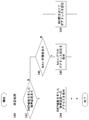
- FIG. 5 is a flowchart showing a connection procedure in the terminal device 10.
- the control unit 18 executes an approval process (S40). If there is a terminal device 10 having a DHCP function (Y in S42), the control unit 18 instructs access to the terminal device 10 having a DHCP function (S44). On the other hand, if there is no terminal device 10 having the DHCP function (N in S42) and the new terminal device 10 has the Auto-IP function (Y in S46), the control unit 18 sets the IP address in Auto-IP. Is instructed (S48). If the new terminal apparatus 10 does not have the Auto-IP function (N in S46), the control unit 18 sets an IP address using the MAC layer method (S50).
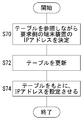
- FIG. 6 is a flowchart showing an IP address setting procedure by the MAC layer method in the terminal device 10. This corresponds to step 50 in FIG.
- the control unit 18 determines the IP address of the requesting terminal device 10 while referring to the table stored in the storage unit 20 (S70).
- the control unit 18 updates the table stored in the storage unit 20 (S72).
- the control unit 18 causes the requesting terminal device 10 to set an IP address based on the table (S74).
- the modification relates to the terminal device 10 similar to the embodiment.
- the terminal device 10 on the response side in the modification forms an ad hoc network when the DHCP server is not included in the ad hoc network and the terminal device 10 on the request side does not have the Auto-IP function.
- An IP address assignment method is determined according to the number of terminal devices 10.
- the control unit 18 in the terminal device 10 on the response side acquires the number of the terminal devices 10 included in the communication system 100 by referring to the address table stored in the storage unit 20. If the number of terminal devices 10 is greater than the threshold value, the control unit 18 executes the MAC layer method described above.
- the control unit 18 determines an IP address based on the MAC address of the requesting terminal device 10. For this purpose, a known technique may be used, and the description thereof is omitted here.
- the IP address assigning means is switched according to the presence or absence of the DHCP server and the presence or absence of the Auto-IP function, the IP address can be assigned according to the configuration of the ad hoc network.
- the IP address can be assigned according to the configuration of the ad hoc network.
- the registration authority assigns an IP address, so that a new terminal device can communicate.
- the terminal device 10 executes the connection process and the transfer process while using the same wireless unit 12 and modem unit 14. That is, both processes are executed using the wireless LAN.
- the present invention is not limited to this.
- another wireless unit 12 and a modem unit 14 may be used for connection processing and transfer processing. That is, the wireless LAN is used for the transfer process, but another communication system may be used for the connection process. The reverse is also possible. According to this modification, the degree of freedom of the configuration of the communication system can be improved.
- the DHCP server assigns an IP address to the new terminal device 10 by executing DHCP.
- the present invention is not limited to this.
- RARP Reverse Address Resolution Protocol
- BOOTP Bootstrap Protocol
- various protocols can be used.
- the present invention in the communication system 100, multi-hop communication by a plurality of terminal devices 10 is performed.
- the present invention is not limited to this.
- only direct communication between the two terminal devices 10 may be performed.
- the degree of freedom of the configuration of the communication system 100 can be improved.
- 10 terminal devices 12 radio units, 14 modulation / demodulation units, 16 processing units, 18 control units, 20 storage units, 22 operation units, 24 monitors, 26 speakers, 100 communication systems.
- an IP address can be assigned according to the configuration of the ad hoc network.
Landscapes
- Engineering & Computer Science (AREA)
- Computer Networks & Wireless Communication (AREA)
- Signal Processing (AREA)
- Databases & Information Systems (AREA)
- Mobile Radio Communication Systems (AREA)
Abstract
制御部18は、承認処理を実行した新たな端末装置に対して、IPアドレスの付与処理を実行する。制御部18は、アドホックネットワーク内にIPアドレスを付与可能なサーバが含まれている場合に、当該サーバへのアクセスを新たな端末装置に指示する。制御部18は、アドホックネットワーク内にIPアドレスを付与可能なサーバが含まれておらず、新たな端末装置が自らIPアドレスを付与可能である場合に、IPアドレスの付与を新たな端末装置に指示する。制御部18は、アドホックネットワーク内にIPアドレスを付与可能なサーバが含まれておらず、新たな端末装置が自らIPアドレスを付与可能でない場合に、IPアドレスを新たな端末装置に付与する。
Description
本発明は、通信技術に関し、特にアドホックネットワークにおける通信方法およびそれを利用した端末装置に関する。
アドホックネットワークは、基地局装置や有線網に依存せずに、端末装置を構成要素とする自立分散形のネットワークである。アドホックネットワークでは、端末装置同士が互いに対等であり、マルチホップを実行することによって情報交換が実行される。このようなアドホックネットワークでのルーティング方式には、テーブル駆動方式、オンデマンド方式、ハイブリッド方式がある。テーブル駆動方式では、各端末装置が、パケット信号のあて先と次のホップ先とを対応づけたルーティングテーブルを維持する。また、各端末装置は、ルーティングテーブルを参照しながら、パケット信号のあて先から次のホップ先を決定する。なお、ルーティングテーブルは、制御パケット信号によって、周期的に更新される。テーブル駆動方式の一例が、DSDV(Destination Sequence Distance Vector)、WRP(Wireless Routing Protocol)、CGSR(Clusterhead Gateway Switch Routing)、OLSR(Optimized Link State Routing)である。
オンデマンド方式では、情報の発生源の端末装置が、パケット信号の転送を要求する際にあて先へのルートを発見する。まず、情報の発生源の端末装置は、問い合わせのためのパケット信号をフラッディング方式により転送することによって、情報の発生源の端末装置への逆向きのルートを学習するとともに、問い合わせのためのパケット信号を受信したあて先の端末装置も応答する。このように発見したルートをもとに、発生源の端末装置からあて先の端末装置へ、パケット信号の転送が実行される。オンデマンド方式の一例が、AODV(Ad hoc On demand Distance Vector)、DSR(Dynamic Source Routing)、TORA(Temporally Ordered Routing Algorithm)、RDMAR(Relative Distance Micro-discovery Ad hoc Routing Protocol)、ABR(Associativity-Based Routing)である。ハイブリッド方式は、テーブル駆動方式とオンデマンド方式とを組み合わせた方式である(例えば、非特許文献1参照)。
また、アドホックネットワークにおいて、端末装置の設定を簡単にする技術が提案されている。所定の端末装置は、通信設定情報を保有しており、当該端末装置に搭載されたICカードリーダライタの直近にタグがかざされる。その結果、ICカードリーダライタは、タグとの間において非接触通信を実行することによって、通信設定情報を送信する。また、当該タグと、別の端末装置に搭載されたICカードリーダライタとの間において、前述と逆の手順が実行されることによって、別の端末装置に通信設定情報が送信される(例えば、特許文献1参照)。
間瀬憲一、中野敬介、仙石正和、篠田庄司、「アドホックネットワーク」、電子情報通信学会誌、日本、電子情報通信学会、2001年2月、84、2、p.127-134
ユーザの利便性を考慮すれば、アドホックネットワークへの端末装置の接続手順は容易である方が望ましい。一方、アドホックネットワークは、複数の端末装置によって形成されているので、他の端末装置への影響を考慮すれば、セキュリティ対策が必要になる。セキュリティの向上を実現するために、アドホックネットワークを形成している複数の端末装置のうちのいずれかに、当該アドホックネットワークへの新たな端末装置の参加を承認すべき役割が割り当てられる(以下、当該役割が割り当てられた端末装置を「登録機関」という)。また、接続手順の容易性の向上を実現するために、接続手順は、登録機関に備えられたボタンが押し下げられてから所定の期間のうちに、新たな端末装置に備えられたボタンが押し下げられた場合に実行される。
また、アドホックネットワークに参加した端末装置が実際に通信を行う際、端末装置にIPアドレスが付与される。例えば、IPアドレスの付与は、DHCP(Dynamic Host Configuration Protocol)やAuto-IPによってなされる。しかしながら、アドホックネットワークには、複数の端末装置が参加しているので、DHCPサーバ機能を搭載した端末装置が参加しているか、Auto-IP機能を搭載した端末装置が参加しているかは、アドホックネットワークの構成によって異なる。また、DHCPサーバ機能を搭載した端末装置やAuto-IP機能を搭載した端末装置が参加している場合、これらの機能との互換性が必要とされる。
本発明はこうした状況に鑑みてなされたものであり、その目的は、アドホックネットワークの構成に応じてIPアドレスを付与する通信技術を提供することにある。
上記課題を解決するために、本発明のある態様の端末装置は、他の端末装置との間においてアドホックネットワークを形成しながら、通信を実行する通信部と、通信部において形成しているアドホックネットワークへの新たな端末装置の参加を承認すべき役割が割り当てられている場合、通信部を介して新たな端末装置からの参加要求を受けつける受付部と、受付部において受けつけた参加要求に対して承認処理を実行する第1処理部と、第1処理部において承認処理を実行した新たな端末装置に対して、IPアドレスの付与処理を実行する第2処理部とを備える。第2処理部は、アドホックネットワーク内にIPアドレスを付与可能な他の端末装置が含まれている場合に、当該他の端末装置へのアクセスを新たな端末装置に指示し、アドホックネットワーク内にIPアドレスを付与可能な他の端末装置が含まれておらず、新たな端末装置が自らIPアドレスを付与可能である場合に、IPアドレスの付与を新たな端末装置に指示し、アドホックネットワーク内にIPアドレスを付与可能な他の端末装置が含まれておらず、新たな端末装置が自らIPアドレスを付与可能でない場合に、IPアドレスを新たな端末装置に付与する。
本発明の別の態様は、通信方法である。この方法は、他の端末装置との間においてアドホックネットワークを形成しながら、通信を実行するステップと、アドホックネットワークへの新たな端末装置の参加を承認すべき役割が割り当てられている場合、新たな端末装置からの参加要求を受けつけるステップと、受けつけた参加要求に対して承認処理を実行するステップと、承認処理を実行した新たな端末装置に対して、IPアドレスの付与処理を実行するステップとを備える。IPアドレスの付与処理を実行するステップは、アドホックネットワーク内にIPアドレスを付与可能な他の端末装置が含まれている場合に、当該他の端末装置へのアクセスを新たな端末装置に指示し、アドホックネットワーク内にIPアドレスを付与可能な他の端末装置が含まれておらず、新たな端末装置が自らIPアドレスを付与可能である場合に、IPアドレスの付与を新たな端末装置に指示し、アドホックネットワーク内にIPアドレスを付与可能な他の端末装置が含まれておらず、新たな端末装置が自らIPアドレスを付与可能でない場合に、IPアドレスを新たな端末装置に付与する。
なお、以上の構成要素の任意の組合せ、本発明の表現を方法、装置、システム、記録媒体、コンピュータプログラムなどの間で変換したものもまた、本発明の態様として有効である。
本発明によれば、アドホックネットワークの構成に応じてIPアドレスを付与できる。
本発明を具体的に説明する前に、概要を述べる。本発明の実施例は、複数の端末装置によって形成されるアドホックネットワークを実行する通信システムに関する。アドホックネットワークにおいて、複数の端末装置のうちのいずれかが、前述の登録機関とされている。また、当該アドホックネットワークへの接続を希望している新たな端末装置が存在する。登録機関は、新たな端末装置に対して承認処理を実行するとともに、新たな端末装置に対してIPアドレスを付与する。IPアドレスの付与は、例えば、DHCPサーバやAuto-IP機能によってなされる。これらが、アドホックネットワーク内に含まれない場合もありえる。一方、アドホックネットワークを構成している端末装置がDHCPサーバの機能を搭載している場合、DCHPサーバとの互換性が必要になる。そのため、本発明の実施例に係る通信システムは、次の処理を実行する。
アドホックネットワーク内において、端末装置の情報を示したテーブルが予めブロードキャスト送信される。当該テーブルでは、IPアドレス、DHCPサーバ機能の有無、Auto-IP機能の有無等が各端末装置に対して示される。登録機関は、新たな端末装置から接続要求を受信すると、新たな端末装置に対して承認処理を実行する。その際、登録機関は、新たな端末装置に搭載されている機能に関する情報も取得する。登録機関は、承認処理の終了後、DHCPサーバ機能を搭載した端末装置(以下、「DHCPサーバ」という)がアドホックネットワーク内に存在していれば、DHCPサーバへのアクセスを新たな端末装置へ指示する。
新たな端末装置は、DHCPサーバへアクセスすることによって、DHCPサーバからIPアドレスを付与される。一方、DHCPサーバがアドホックネットワーク内に存在しておらず、新たな端末装置がAuto-IP機能を搭載していれば、登録機関は、Auto-IP機能によるIPアドレス付与を新たな端末装置に指示する。さらに、DHCPサーバがアドホックネットワーク内に存在しておらず、新たな端末装置がAuto-IP機能を搭載していなければ、登録機関は、MAC層方式にて新たな端末装置にIPアドレスを付与する。
通信システムは、主として、(1)アドホックネットワークへの新たな端末装置の接続処理(以下、「接続処理」という)、(2)アドホックネットワークでのデータ信号の転送処理(以下、「転送処理」という)を実行する。なお、前述の承認処理およびIPアドレスの付与処理は、(1)の接続処理に含まれる。
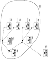
図1は、本発明の実施例に係る通信システム100の構成を示す。通信システム100は、端末装置10と総称される第1端末装置10a、第2端末装置10b、第3端末装置10c、第4端末装置10d、第5端末装置10e、第6端末装置10f、第7端末装置10gを含む。また、第N端末装置10nが、通信システム100に含まれようとしている。
複数の端末装置10、例えば、第1端末装置10aから第7端末装置10gは、アドホックネットワークを形成することによって通信を実行する。なお、アドホックネットワークを構成している端末装置10は、第1端末装置10aから第7端末装置10gに限定されない。また、複数の端末装置10は、例えば、IEEE802.11等の規格に準拠した無線LANシステムに対応する。また、アドホックネットワークでのルーティング方式は、前述のごとく、テーブル駆動方式、オンデマンド方式、ハイブリッド方式等の公知の技術に対応していればよく、例えば、テーブル駆動方式の場合、公知の技術によって、ルーティングテーブルが更新される。
複数の端末装置10うちのいずれか、例えば、第3端末装置10cには、通常のアドホックネットワークでの通信機能に加えて、アドホックネットワークへの新たな端末装置10の参加を承認すべき役割が割り当てられている。つまり、第3端末装置10cが、前述の登録機関に相当する。ここで、登録機関での処理は後述するが、登録機関は、アドホックネットワークへの参加資格を発行したり、取り消したりするような権限を有した端末装置10といえる。また、登録機関の機能は、第3端末装置10c以外の端末装置10にも備えられているが、現状において休止されているものとする。ここでは、説明を明瞭にするために、通信システム100の中に、ひとつの登録機関が含まれいてるものとする。新たな端末装置10、つまり第N端末装置10nは、複数の端末装置10によって形成されたアドホックネットワークへの参加を要求する。ここで、第N端末装置10nは、登録機関に対して参加を要求し、登録機関によって参加が許可された場合に、通信システム100の構成要素となる。以下の説明では、便宜上、第N端末装置10nを「要求側」とよび、登録機関を「応答側」とよぶ場合がある。
以上のような新たな端末装置10の承認処理の他に、登録機関は、新たな端末装置10に対するIPアドレスの付与処理を実行する。ここで、通信システム100の中に、DHCPサーバ機能を搭載した端末装置10(以下、前述のごとく「DHCPサーバ」ということもある)が含まれている場合もあれば、新たな端末装置10がAuto-IP機能を搭載している場合もある。例えば、第2端末装置10bがDHCPサーバに相当する。あるいは、これら両方の場合に該当しないこともある。つまり、通信システム100を形成している各端末装置10の機能によって、IPアドレスを付与する手順が異なる。そのような場合であっても、新たな端末装置10に確実にIPアドレスが設定されることが要求される。また、DHCPサーバが含まれている場合に、DHCPサーバとの互換性も要求される。
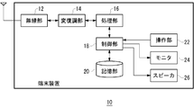
図2は、端末装置10の構成を示す。端末装置10は、無線部12、変復調部14、処理部16、制御部18、記憶部20、操作部22、モニタ24、スピーカ26を含む。なお、図1には、複数の端末装置10が示されており、さらに、要求側、応答側に対応した端末装置10も示されているが、すべての端末装置10は、図2のような構成を有する。
無線部12は、他の端末装置10との間においてアドホックネットワークを形成しながら、通信を実行する。無線部12は、受信処理として、アンテナを介して受信した無線周波数の信号に対して周波数変換を実行し、ベースバンドの信号を生成する。さらに、無線部12は、ベースバンドの信号を変復調部14に出力する。一般的に、ベースバンドの信号は、同相成分と直交成分によって形成されるので、ふたつの信号線が示されるべきであるが、ここでは、図を明瞭にするためにひとつの信号線だけを示すものとする。また、無線部12には、LNA(Low Noise Amplifier)、ミキサ、AGC、A/D変換部も含まれる。
無線部12は、送信処理として、変復調部14から入力したベースバンドの信号に対して周波数変換を実行し、無線周波数の信号を生成する。さらに、無線部12は、無線周波数の信号をアンテナから送信する。また、無線部12には、PA(Power Amplifier)、ミキサ、D/A変換部も含まれる。
変復調部14は、受信処理として、無線部12からのベースバンドの信号に対して、復調を実行する。さらに、変復調部14は、復調した結果を処理部16に出力する。また、変復調部14は、送信処理として、処理部16からの信号に対して、変調を実行する。さらに、変復調部14は、変調した結果をベースバンドの信号として無線部12に出力する。なお、IEEE802.11a規格のようなOFDM変調方式に端末装置10が対応する場合、変復調部14は、受信処理としてFFTも実行し、送信処理としてIFFTも実行する。また、IEEE802.11b規格のようなスペクトル拡散方式に端末装置10が対応する場合、変復調部14は、受信処理として逆拡散も実行し、送信処理として拡散も実行する。さらに、IEEE802.11nのようなMIMO方式に端末装置10が対応する場合、変復調部14は、受信処理としてアダプティブアレイ信号処理も実行し、送信処理として複数のストリームへの分散処理も実行する。
処理部16は、変復調部14からの信号および変復調部14への信号に対して、デジタル信号処理を実行する。ここで、デジタル信号処理の一例は、送信処理としての誤り訂正の符号化、受信処理としての誤り訂正の復号である。なお、デジタル信号処理は、これに限定されるものではない。また、処理部16は、変復調部14からの信号に対してデジタル信号処理を実行した結果を制御部18に出力し、変復調部14への信号の元になる信号を制御部18から入力する。
制御部18は、端末装置10全体の動作を制御する。制御部18が実行する処理は、主として、前述の(1)接続処理、(2)転送処理に加えて、(3)データの入出力処理に分類される。ここでは、説明の便宜上、(3)を説明し、これに続いて(1)、(2)を説明する。まず、(3)データの入出力処理を説明する。制御部18は、出力処理として、処理部16から、デジタル信号処理された結果を受けつけ、モニタ24、スピーカ26に出力する。また、制御部18は、入力処理として、操作部22から指示信号を受けつけ、それに応じたデータを処理部16に出力する。ここで、操作部22は、ボタン等によって構成されている。また、パーソナルコンピュータと接続されるように端末装置10が形成されている場合に、操作部22は、パーソナルコンピュータに備えられたキーボード、マウスであってもよい。
次に、(1)接続処理を説明する。接続処理は、要求側の端末装置10と応答側の端末装置10との間において実行されており、ここでは、要求側の端末装置10における制御部18の処理を説明した後に、応答側の端末装置10における制御部18の処理を説明する。なお、要求側の端末装置10は、図1の第N端末装置10nに相当し、応答側の端末装置10は、図1の第3端末装置10cに相当する。
要求側の端末装置10における制御部18は、操作部22でのボタンがユーザによって押し下げられたことを検知すると、要求モードになる。要求モードになると、制御部18は、登録機関に対して、アドホックネットワークへの参加要求の旨が示されたパケット信号(以下、「要求信号」という)を送信するように、処理部16から無線部12を制御する。その際、要求信号と一緒にあるいは別に、制御部18は、本端末装置10にて実行可能な機能の一覧が示された情報(以下、「能力情報」という)も、処理部16、変復調部14、無線部12から送信させる。なお、能力情報は、通信システム100を形成している複数の端末装置10間において交換されていてもよい。
なお、能力情報には、例えば、本端末装置10がDHCPサーバであるか否か、本端末装置10がAuto-IP機能を有しているか否かの情報が含まれる。その後、無線部12から処理部16が、要求信号を送信した登録機関から、参加許可の旨が示されたパケット信号(以下、「許可信号」という)を受信する。また、許可信号は、制御部18に入力される。これに続いて、制御部18は、IPアドレスの付与処理を必要に応じて実行する。なお、IPアドレスの付与処理については、応答側の端末装置10における処理において説明する。その後、制御部18は、通信モードになる。通信モードになると、制御部18は、無線部12から処理部16に対して、アドホックネットワークに参加することによって、通信を実行するように制御する。
通信システム100に参加している端末装置10における制御部18は、無線部12から処理部16を介して、他の端末装置10との間で、各端末装置10のアドレス等が示されたテーブルを交換する。このようなテーブルは、新たな端末装置10が通信システム100に参加したときや、新たな端末装置10が通信システム100から離脱したときに更新される。制御部18は、交換したテーブルを記憶部20に記憶する。また、端末装置10間でテーブルを交換することによって、通信システム100に参加している端末装置10間で、アドレス等の情報が共有される。
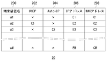
テーブルの交換は、MAC層にてなされる。図3は、記憶部20に記憶されたアドレスのテーブルのデータ構造を示す。端末装置名欄200、DHCP欄202、Auto-IP欄204、IPアドレス欄206、MACアドレス欄208が含まれる。端末装置名欄200は、端末装置10を識別するための名称が示されている。DHCP欄202、Auto-IP欄204は、前述の能力情報をもとに付加される。IPアドレス欄206、MACアドレス欄208は、各端末装置10に対応したIPアドレス、MACアドレスが示される。図2に戻る。
応答側の端末装置10における制御部18は、操作部22での所定のボタンがユーザによって押し下げられたことを検知すると、承認モードになる。承認モードとは、承認処理を実行可能な状態である。承認モードになると、制御部18は、無線部12から処理部16を介して、所定の期間にわたって、要求側の端末装置10からの要求信号を受けつける。制御部18は、受けつけた要求信号に対して承認処理を実行する。ここで、承認処理には、公知の技術が使用されればよい。例えば、制御部18は、無線部12から処理部16を介して、要求側の端末装置10と公開鍵の交換をした後に、要求側の端末装置10に対する認証処理および身分証明処理を実行する。
ここで、認証処理には、「デバイス パスワード」が使用されればよい。また、制御部18は、無線部12から処理部16を介して、要求側の端末装置10から能力情報を受けつける。制御部18は、参加を許可した場合に、処理部16から無線部12を介して、要求側の端末装置10へ許可信号を送信する。一方、制御部18は、参加を拒否した場合に、処理部16から無線部12を介して、要求側の端末装置10へ拒否信号を送信する。
制御部18は、承認処理を実行した要求側の端末装置10に対して、IPアドレスの付与処理を実行する。制御部18は、記憶部20に記憶したアドレスのテーブルを参照することによって、アドホックネットワーク内にDHCPサーバ、つまりIPアドレスを付与可能なサーバが含まれているかを確認する。DHCPサーバが含まれている場合、制御部18は、処理部16から無線部12を介して、要求側の端末装置10へ、DHCPサーバのIPアドレスを通知することによって、DHCPサーバへのアクセスを指示する。例えば、制御部18は、第2端末装置10bがDHCPサーバである場合に、第2端末装置10bのIPアドレスを通知する。要求側の端末装置10における制御部18は、許可信号の受信後、応答側の端末装置10から、DHCPサーバのIPアドレスを受信すると、当該IPアドレスをもとにDHCPサーバへアクセスする。
要求側の端末装置10とDHCPサーバとの間におけるIPアドレス設定の処理には公知の技術が使用されればよい。ここで、簡単に説明すると、制御部18は、コンフィギュレーション設定要求を開始し、DHCPサーバからの返信を待つ。また、制御部18は、返信としてDHCP情報を受けつけると、コンフィギュレーション送付を開始し、DHCPサーバからのACKを待つ。制御部18は、DHCPサーバからのACKを受けつけると、IPアドレス設定の処理が終了される。その後、要求側の端末装置10あるいはDHCPサーバは、設定されたIPアドレスを応答側の端末装置10へ報告する。応答側の端末装置10における制御部18は、報告に応じてテーブルを更新する。なお、テーブルの更新は、DHCPサーバにおいてなされてもよい。
一方、制御部18は、記憶部20に記憶したアドレスのテーブルを参照した結果、アドホックネットワーク内にDHCPが含まれていない場合、要求側の端末装置10がAuto-IP機能を搭載しているか、つまり自らIPアドレスを付与可能であるかを確認する。当該確認は、要求側の端末装置10からの能力情報をもとになされる。Auto-IP機能が搭載されている場合、制御部18は、要求側の端末装置10に対して、Auto-IP機能によるIPアドレスの付与を指示する。Auto-IP機能として公知の技術が使用されればよい。
ここで、簡単に説明すると、制御部18は、乱数によりリンクローカルアドレス範囲内のIPアドレスをひとつ選択し、選択したIPアドレスに対するARP要求をブロードキャスト送信する。ARP要求に返信があれば、当該IPアドレスは、通信システム100において使用されているので、制御部18は、別のIPアドレスを選択してARP要求を再びブロードキャスト送信する。以上の処理は、ARP要求に対する返信がなくなるまで続けられ、制御部18は、未使用と判断したIPアドレスを設定する。その後、要求側の端末装置10は、設定されたIPアドレスを応答側の端末装置10へ報告する。応答側の端末装置10における制御部18は、報告に応じてテーブルを更新する。
一方、制御部18は、能力情報を確認した結果、要求側の端末装置10にAuto-IP機能が搭載されていない場合、MAC層方式にて、IPアドレスを要求側の端末装置10に付与する。具体的に説明すると、制御部18は、記憶部20に記憶したアドレスのテーブルを参照することによって、空きIPアドレスを探索し、要求側の端末装置10のIPアドレスとして空きIPアドレスを選択する。また、制御部18は、選択したIPアドレスと要求側の端末装置10のMACアドレスとの組合せを追加するように、アドレスのテーブルを更新する。制御部18は、更新したアドレスのテーブルをブロードキャスト送信する。要求側の端末装置10における制御部18は、アドレスのテーブルを受けつけ、自らのMACアドレスに対応したIPアドレスを抽出する。さらに、制御部18は、抽出したIPアドレスを設定する。
以上の処理が終了してから一定期間の経過後、あるいは要求モードになってから一定期間の経過後、要求側の端末装置10における制御部18は、通信モードになる。通信モードになると、制御部18は、無線部12から処理部16に対して、アドホックネットワークに参加することによって、通信を実行するように制御する。
次に、(2)転送処理を説明する。転送処理のためにルーティングテーブルが生成されるが、ルーティングテーブルの生成には、公知の技術が使用されればよい。制御部18は、生成したルーティングテーブルを記憶部20に記憶する。転送処理において、制御部18は、無線部12から処理部16を介して受信したパケット信号のあて先アドレスを取得する。また、記憶部20に記憶されたルーティングテーブルを参照しながら、制御部18は、取得したあて先アドレスに対応したホップ先アドレスを特定する。さらに、制御部18は、特定したホップ先アドレスへ、処理部16から無線部12を介してパケット信号を送信する。
なお、転送処理の段階においても、前述のごとく、アドレスのテーブルが更新されると、アドレスのテーブルはブロードキャスト送信される。例えば、所定の端末装置10が、別の端末装置10の離脱を検出した場合に、当該別の端末装置10に関する情報を削除するようにアドレスのテーブルを更新する。ここで、別の端末装置10の離脱は、当該別の端末装置10からの応答が所定の期間にわたってない場合に、検出される。また、所定の端末装置10は、更新したアドレスのテーブルをブロードキャスト送信する。
この構成は、ハードウエア的には、任意のコンピュータのCPU、メモリ、その他のLSIで実現でき、ソフトウエア的にはメモリにロードされた通信機能のあるプログラムなどによって実現されるが、ここではそれらの連携によって実現される機能ブロックを描いている。したがって、これらの機能ブロックがハードウエアのみ、ソフトウエアのみ、またはそれらの組合せによっていろいろな形で実現できることは、当業者には理解されるところである。
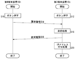
以上の構成による通信システム100の動作を説明する。図4は、通信システム100における接続手順を示すシーケンス図である。第N端末装置10nのボタンが押し下げられ(S10)、第3端末装置10cのボタンも押し下げられる(S12)。第N端末装置10nは、第3端末装置10cに対して、要求信号を送信する(S14)。第3端末装置10cは、第N端末装置10nに対する承認処理を実行する(S16)。第3端末装置10cは、第N端末装置10nに対して、許可信号を送信する(S18)。また、第3端末装置10cは、IPアドレスの付与処理を実行する(S20)。
図5は、端末装置10における接続手順を示すフローチャートである。制御部18は、承認処理を実行する(S40)。DHCP機能を有した端末装置10があれば(S42のY)、制御部18は、DHCP機能を有した端末装置10へのアクセスを指示する(S44)。一方、DHCP機能を有した端末装置10がなく(S42のN)、新たな端末装置10にAuto-IP機能があれば(S46のY)、制御部18は、Auto-IPでのIPアドレス設定を指示する(S48)。また、新たな端末装置10にAuto-IP機能がなければ(S46のN)、制御部18は、MAC層方式にてIPアドレスを設定する(S50)。
図6は、端末装置10におけるMAC層方式によるIPアドレスの設定手順を示すフローチャートである。これは、図5のステップ50に相当する。制御部18は、記憶部20に記憶したテーブルを参照しながら、要求側の端末装置10のIPアドレスを決定する(S70)。制御部18は、記憶部20に記憶したテーブルを更新する(S72)。制御部18は、要求側の端末装置10に対して、テーブルをもとにIPアドレスを設定させる(S74)。
次に変形例を説明する。変形例は、実施例と同様の端末装置10に関する。変形例における応答側の端末装置10は、アドホックネットワーク内にDHCPサーバが含まれておらず、要求側の端末装置10がAuto-IP機能を搭載していない場合に、アドホックネットワークを形成している端末装置10の数に応じて、IPアドレスの付与方法を決定する。応答側の端末装置10における制御部18は、記憶部20に記憶されたアドレスのテーブルを参照することによって、通信システム100に含まれた端末装置10の数を取得する。端末装置10の数がしきい値よりも多ければ、制御部18は、前述のMAC層方式を実行する。一方、端末装置10の数がしきい値以下であれば、制御部18は、要求側の端末装置10のMACアドレスをもとにIPアドレスを決定させる。これには、公知の技術が使用されればよいので、ここでは説明を省略する。
本発明の実施例によれば、DHCPサーバの有無、Auto-IP機能の有無に応じて、IPアドレスの付与手段を切り替えるので、アドホックネットワークの構成に応じてIPアドレスを付与できる。また、DHCPサーバがある場合や、Auto-IP機能がある場合に、それらを優先的に使用するので、それらとの互換性を維持できる。また、DHCPサーバがあれば、それを優先的に使用するので、IPアドレスを確実に付与できる。また、アドホックネットワークの構成が変更される場合でも、新たな端末装置にIPアドレスを付与できる。また、DHCPサーバやAuto-IP機能がない場合でも、登録機関がIPアドレスを付与するので、新たな端末装置の通信を可能にできる。
以上、本発明を実施例をもとに説明した。この実施例は例示であり、それらの各構成要素や各処理プロセスの組合せにいろいろな変形例が可能なこと、またそうした変形例も本発明の範囲にあることは当業者に理解されるところである。
本発明の実施例において、端末装置10は、同一の無線部12および変復調部14を使用しながら、接続処理を実行するとともに、転送処理を実行する。つまり、両方の処理が無線LANを使用しながら実行される。しかしながらこれに限らず例えば、接続処理と転送処理のために、別の無線部12および変復調部14が使用されてもよい。つまり、転送処理には無線LANが使用されるが、接続処理には別の通信システムが使用されてもよい。また、その逆でもよい。本変形例によれば、通信システムの構成の自由度を向上できる。
本発明の実施例において、DHCPサーバがDHCPを実行することによって新たな端末装置10にIPアドレスを付与している。しかしながらこれに限らず例えば、RARP(Reverse Address Resolution Protocol)、BOOTP(Bootstrap Protocol)であってもよい。本変形例によれば、さまざまなプロトコルを使用できる。
本発明の実施例において、通信システム100では、複数の端末装置10によるマルチホップ通信がなされている。しかしながらこれに限らず例えば、ふたつの端末装置10間の直接通信のみがなされていてもよい。本変形例によれば、通信システム100の構成の自由度を向上できる。
10 端末装置、 12 無線部、 14 変復調部、 16 処理部、 18 制御部、 20 記憶部、 22 操作部、 24 モニタ、 26 スピーカ、 100 通信システム。
本発明によれば、アドホックネットワークの構成に応じてIPアドレスを付与できる。
Claims (3)
- 他の端末装置との間においてアドホックネットワークを形成しながら、通信を実行する通信部と、
前記通信部において形成しているアドホックネットワークへの新たな端末装置の参加を承認すべき役割が割り当てられている場合、前記通信部を介して新たな端末装置からの参加要求を受けつける受付部と、
前記受付部において受けつけた参加要求に対して承認処理を実行する第1処理部と、
前記第1処理部において承認処理を実行した新たな端末装置に対して、IPアドレスの付与処理を実行する第2処理部とを備え、
前記第2処理部は、アドホックネットワーク内にIPアドレスを付与可能な他の端末装置が含まれている場合に、当該他の端末装置へのアクセスを新たな端末装置に指示し、アドホックネットワーク内にIPアドレスを付与可能な他の端末装置が含まれておらず、新たな端末装置が自らIPアドレスを付与可能である場合に、IPアドレスの付与を新たな端末装置に指示し、アドホックネットワーク内にIPアドレスを付与可能な他の端末装置が含まれておらず、新たな端末装置が自らIPアドレスを付与可能でない場合に、IPアドレスを新たな端末装置に付与することを特徴とする端末装置。 - 前記第2処理部は、アドホックネットワーク内にIPアドレスを付与可能な他の端末装置が含まれておらず、新たな端末装置が自らIPアドレスを付与可能でない場合に、アドホックネットワークを形成している端末装置の数がしきい値よりも多ければ、IPアドレスを新たな端末装置に付与し、アドホックネットワークを形成している端末装置の数がしきい値以下であれば、新たな端末装置のMACアドレスをもとにIPアドレスを決定させることを特徴とする請求項1に記載の端末装置。
- 他の端末装置との間においてアドホックネットワークを形成しながら、通信を実行するステップと、
アドホックネットワークへの新たな端末装置の参加を承認すべき役割が割り当てられている場合、新たな端末装置からの参加要求を受けつけるステップと、
受けつけた参加要求に対して承認処理を実行するステップと、
承認処理を実行した新たな端末装置に対して、IPアドレスの付与処理を実行するステップとを備え、
前記IPアドレスの付与処理を実行するステップは、アドホックネットワーク内にIPアドレスを付与可能な他の端末装置が含まれている場合に、当該他の端末装置へのアクセスを新たな端末装置に指示し、アドホックネットワーク内にIPアドレスを付与可能な他の端末装置が含まれておらず、新たな端末装置が自らIPアドレスを付与可能である場合に、IPアドレスの付与を新たな端末装置に指示し、アドホックネットワーク内にIPアドレスを付与可能な他の端末装置が含まれておらず、新たな端末装置が自らIPアドレスを付与可能でない場合に、IPアドレスを新たな端末装置に付与することを特徴とする通信方法。
Priority Applications (1)
| Application Number | Priority Date | Filing Date | Title |
|---|---|---|---|
| US13/120,133 US8452895B2 (en) | 2008-09-19 | 2009-08-26 | Communication method and terminal apparatuses using the communication method in an ad-hoc network |
Applications Claiming Priority (2)
| Application Number | Priority Date | Filing Date | Title |
|---|---|---|---|
| JP2008-240824 | 2008-09-19 | ||
| JP2008240824A JP5072788B2 (ja) | 2008-09-19 | 2008-09-19 | 通信方法およびそれを利用した端末装置 |
Publications (1)
| Publication Number | Publication Date |
|---|---|
| WO2010032382A1 true WO2010032382A1 (ja) | 2010-03-25 |
Family
ID=42039234
Family Applications (1)
| Application Number | Title | Priority Date | Filing Date |
|---|---|---|---|
| PCT/JP2009/004146 Ceased WO2010032382A1 (ja) | 2008-09-19 | 2009-08-26 | 通信方法およびそれを利用した端末装置 |
Country Status (3)
| Country | Link |
|---|---|
| US (1) | US8452895B2 (ja) |
| JP (1) | JP5072788B2 (ja) |
| WO (1) | WO2010032382A1 (ja) |
Cited By (1)
| Publication number | Priority date | Publication date | Assignee | Title |
|---|---|---|---|---|
| WO2015098029A1 (ja) * | 2013-12-27 | 2015-07-02 | 日本電気株式会社 | 無線通信装置、無線通信ネットワーク、識別番号設定方法 |
Families Citing this family (11)
| Publication number | Priority date | Publication date | Assignee | Title |
|---|---|---|---|---|
| US9372728B2 (en) * | 2009-12-03 | 2016-06-21 | Ol Security Limited Liability Company | System and method for agent networks |
| CN102209164B (zh) | 2010-03-29 | 2014-07-02 | 京瓷办公信息系统株式会社 | 图像形成系统、图像形成装置以及图像形成装置搜索方法 |
| JP5597624B2 (ja) | 2010-12-29 | 2014-10-01 | ノキア コーポレイション | 短距離通信を介したネットワーク設定 |
| KR102005771B1 (ko) | 2012-02-24 | 2019-10-01 | 삼성전자주식회사 | 무선 통신 네트워크에서 ip 주소 할당 방법 및 장치 |
| US8830869B2 (en) * | 2012-07-18 | 2014-09-09 | Accedian Networks Inc. | Systems and methods of detecting and assigning IP addresses to devices with ARP requests |
| US9992021B1 (en) | 2013-03-14 | 2018-06-05 | GoTenna, Inc. | System and method for private and point-to-point communication between computing devices |
| US9432329B2 (en) * | 2013-09-13 | 2016-08-30 | Netapp, Inc. | Network address assignment with duplication detection |
| US9756549B2 (en) | 2014-03-14 | 2017-09-05 | goTenna Inc. | System and method for digital communication between computing devices |
| CN105991624B (zh) * | 2015-03-06 | 2019-07-26 | 阿里巴巴集团控股有限公司 | 一种服务器的安全管理方法及装置 |
| WO2020185707A1 (en) | 2019-03-08 | 2020-09-17 | goTenna Inc. | Method for utilization-based traffic throttling in a wireless mesh network |
| CN115515207B (zh) * | 2022-09-20 | 2025-12-19 | 湖北星纪魅族科技有限公司 | 通信方法、装置、电子设备和计算机可读存储介质 |
Citations (4)
| Publication number | Priority date | Publication date | Assignee | Title |
|---|---|---|---|---|
| JP2003273873A (ja) * | 2002-03-13 | 2003-09-26 | Brother Ind Ltd | 電子機器、プログラム |
| JP2005348337A (ja) * | 2004-06-07 | 2005-12-15 | Hitachi Ltd | 通信機器、通信システム、通信システムの制御方法、及びプログラム |
| JP2007006190A (ja) * | 2005-06-24 | 2007-01-11 | Nikon Corp | 通信制御装置、通信制御方法、および撮像装置 |
| JP2007082070A (ja) * | 2005-09-16 | 2007-03-29 | Nippon Telegr & Teleph Corp <Ntt> | 無線通信装置 |
Family Cites Families (7)
| Publication number | Priority date | Publication date | Assignee | Title |
|---|---|---|---|---|
| US6892230B1 (en) * | 1999-06-11 | 2005-05-10 | Microsoft Corporation | Dynamic self-configuration for ad hoc peer networking using mark-up language formated description messages |
| US7443862B2 (en) * | 2002-01-22 | 2008-10-28 | Canon Kabushiki Kaisha | Apparatus connected to network, and address determination program and method |
| CA2478905A1 (en) * | 2002-03-15 | 2003-09-25 | Meshnetworks, Inc. | System and method for auto-configuration and discovery of ip to mac address mapping and gateway presence |
| JP3748106B2 (ja) | 2002-04-25 | 2006-02-22 | ソニー株式会社 | 通信システム、情報処理装置および方法、記録媒体、並びにプログラム |
| EP1429522B1 (en) * | 2002-12-13 | 2008-08-27 | Sony Deutschland GmbH | Network topology aware configuration of network addresses in wireless networks |
| KR100628112B1 (ko) * | 2004-12-30 | 2006-09-26 | 엘지전자 주식회사 | 다중 도약 접속 방식이 적용되는 네트워크 영역에서,이동통신 단말기를 이용한 아이피 주소 설정 제어 방법 |
| US20070002833A1 (en) * | 2005-06-30 | 2007-01-04 | Symbol Technologies, Inc. | Method, system and apparatus for assigning and managing IP addresses for wireless clients in wireless local area networks (WLANs) |
-
2008
- 2008-09-19 JP JP2008240824A patent/JP5072788B2/ja not_active Expired - Fee Related
-
2009
- 2009-08-26 US US13/120,133 patent/US8452895B2/en not_active Expired - Fee Related
- 2009-08-26 WO PCT/JP2009/004146 patent/WO2010032382A1/ja not_active Ceased
Patent Citations (4)
| Publication number | Priority date | Publication date | Assignee | Title |
|---|---|---|---|---|
| JP2003273873A (ja) * | 2002-03-13 | 2003-09-26 | Brother Ind Ltd | 電子機器、プログラム |
| JP2005348337A (ja) * | 2004-06-07 | 2005-12-15 | Hitachi Ltd | 通信機器、通信システム、通信システムの制御方法、及びプログラム |
| JP2007006190A (ja) * | 2005-06-24 | 2007-01-11 | Nikon Corp | 通信制御装置、通信制御方法、および撮像装置 |
| JP2007082070A (ja) * | 2005-09-16 | 2007-03-29 | Nippon Telegr & Teleph Corp <Ntt> | 無線通信装置 |
Cited By (1)
| Publication number | Priority date | Publication date | Assignee | Title |
|---|---|---|---|---|
| WO2015098029A1 (ja) * | 2013-12-27 | 2015-07-02 | 日本電気株式会社 | 無線通信装置、無線通信ネットワーク、識別番号設定方法 |
Also Published As
| Publication number | Publication date |
|---|---|
| US8452895B2 (en) | 2013-05-28 |
| US20110208846A1 (en) | 2011-08-25 |
| JP5072788B2 (ja) | 2012-11-14 |
| JP2010074610A (ja) | 2010-04-02 |
Similar Documents
| Publication | Publication Date | Title |
|---|---|---|
| JP5072788B2 (ja) | 通信方法およびそれを利用した端末装置 | |
| JP7645382B2 (ja) | マルチリンクピアツーピア通信のための通信装置および通信方法 | |
| US9113393B2 (en) | System, method and apparatus for wireless network connection using near field communication | |
| US20160191642A1 (en) | Low power digital radio range extension | |
| US20090274065A1 (en) | Method and apparatus for setting wireless local area network by using button | |
| US9370031B2 (en) | Wireless network setup and configuration distribution system | |
| JP2019525518A (ja) | ネットワーク化されたデバイス間のネットワーククラスターを確立するための方法 | |
| JP4281768B2 (ja) | 通信システム、無線通信装置およびその制御方法 | |
| JP5820106B2 (ja) | 通信装置、および、その制御方法 | |
| JP4922812B2 (ja) | 通信方法ならびにそれを利用した端末装置および通信システム | |
| JP4413254B2 (ja) | 通信方法およびそれを利用した端末装置 | |
| JP4799469B2 (ja) | 通信方法およびそれを利用した端末装置 | |
| US20060265333A1 (en) | Mesh network with digital rights management interoperability | |
| US7940760B2 (en) | Method and apparatus for discovering component in at least one sub-network | |
| JP2003348103A (ja) | 無線通信装置及び無線通信システム並びに無線通信方法 | |
| JP2010034945A (ja) | 通信システム、認証サーバおよび通信方法 | |
| JP2011199732A (ja) | 無線lanシステム、移動端末及び移動端末のipアドレス切替方法 | |
| JP2010098687A (ja) | 通信方法およびそれを利用した端末装置 | |
| JP4874158B2 (ja) | 通信方法およびそれを利用した端末装置 | |
| JP2006054707A (ja) | 無線lanのアドホックモードにおける通信装置、設定プログラム及び接続方法 | |
| JPWO2008132808A1 (ja) | 通信方法およびそれを利用した通信システム | |
| JP4307350B2 (ja) | アドホック・マルチホップ通信システムおよびその無線端末ならびにアドホック・マルチホップネットワークの接続方法 | |
| JP4628913B2 (ja) | 無線通信装置 | |
| JP6330180B2 (ja) | 中継装置、及び、中継方法 | |
| JP2006211347A (ja) | 無線通信システム |
Legal Events
| Date | Code | Title | Description |
|---|---|---|---|
| 121 | Ep: the epo has been informed by wipo that ep was designated in this application |
Ref document number: 09814228 Country of ref document: EP Kind code of ref document: A1 |
|
| NENP | Non-entry into the national phase |
Ref country code: DE |
|
| WWE | Wipo information: entry into national phase |
Ref document number: 13120133 Country of ref document: US |
|
| 122 | Ep: pct application non-entry in european phase |
Ref document number: 09814228 Country of ref document: EP Kind code of ref document: A1 |