WO2010029953A1 - 3次元位置指定装置、3次元位置指定方法および3次元位置指定用プログラム、ならびにボクセルモデリング装置、ボクセルモデリング方法およびボクセルモデリング用プログラム - Google Patents
3次元位置指定装置、3次元位置指定方法および3次元位置指定用プログラム、ならびにボクセルモデリング装置、ボクセルモデリング方法およびボクセルモデリング用プログラム Download PDFInfo
- Publication number
- WO2010029953A1 WO2010029953A1 PCT/JP2009/065770 JP2009065770W WO2010029953A1 WO 2010029953 A1 WO2010029953 A1 WO 2010029953A1 JP 2009065770 W JP2009065770 W JP 2009065770W WO 2010029953 A1 WO2010029953 A1 WO 2010029953A1
- Authority
- WO
- WIPO (PCT)
- Prior art keywords
- dimensional
- voxel
- dimensional position
- space
- carpet
- Prior art date
- Legal status (The legal status is an assumption and is not a legal conclusion. Google has not performed a legal analysis and makes no representation as to the accuracy of the status listed.)
- Ceased
Links
Images


Classifications
-
- G—PHYSICS
- G06—COMPUTING OR CALCULATING; COUNTING
- G06T—IMAGE DATA PROCESSING OR GENERATION, IN GENERAL
- G06T17/00—Three dimensional [3D] modelling, e.g. data description of 3D objects
Definitions
- the present invention relates to a three-dimensional position specifying device for specifying a three-dimensional position in a three-dimensional space, a three-dimensional position specifying method, a program for specifying a three-dimensional position, and voxel modeling for expressing a three-dimensional shape as a set of voxels.
- the present invention relates to an apparatus, a voxel modeling method, and a program for voxel modeling.
- an object of the present invention is to make it possible to easily and accurately specify a three-dimensional position in a three-dimensional space by specifying the two-dimensional position in the two-dimensional space.
- Another object of the present invention is to easily represent a three-dimensional shape by specifying a two-dimensional position in a two-dimensional space.
- the three-dimensional position designation device, the three-dimensional position designation method, the three-dimensional position designation program, the voxel modeling apparatus, the voxel modeling method, and the voxel modeling program according to the present invention employ the following means to achieve the above-described object. ing.
- the three-dimensional position designation device is: A three-dimensional position designation device for designating a three-dimensional position in a three-dimensional space, Two-dimensional position specifying means for specifying a two-dimensional position in a two-dimensional space; A two-dimensional position designated by the two-dimensional position designation means of the Nth stage Sherpinski carpet having an array of 8 N squares (where “N” is an integer equal to or greater than 1).
- the present inventors have intensively studied to make it possible to specify a three-dimensional position in a three-dimensional space easily and accurately, and as a result, a Sherpinsky carpet, which is one of fractals, and a set of a plurality of voxels. I came to pay attention to the voxel space.
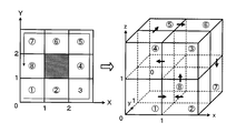
- the Sherpinski carpet divides one square area into nine equal parts, and the process of generating an array of eight square areas using the central square area as a blank area (fractal expansion) excludes square areas that are blank areas. It is a fractal with self-similarity obtained by sequentially applying to a square region.
- the square area of 1 is the initiator (8 0) the fractal expand one blank area and 8 the (first stage of the fractal development) is performed on the square area (8 1) sequence is generated in eight
- the fractal deployed for each square area (second stage of the fractal development) is performed 64
- sequences of the square area of excluding the blank area (and one blank area new 8) is generated, further, when the fractal expansion for each 64 square area except for the blank region (third stage of the fractal development) is performed 512 (8 3 ) sequence of the square area (and new 8 two blank areas) will occur in the.
- the present inventors have found commonality between the characteristics of the Shelpinsky carpet and the characteristics of a voxel space composed of a plurality of voxels, and using the commonality, the three-dimensional position in the three-dimensional space is found. Is to be specified. That is, the three-dimensional position specifying apparatus according to the present invention predetermines a square area corresponding to the two-dimensional position specified on the two-dimensional space of the Nth stage Sherpinski carpet having an array of 8 N square areas.
- a position in the voxel space of one voxel corresponding to the position is acquired, and a three-dimensional position (for example, three-dimensional coordinates) in a three-dimensional space (for example, a three-dimensional coordinate system) is acquired from the position in the voxel space of the one voxel.
- a three-dimensional position for example, three-dimensional coordinates
- a three-dimensional space for example, a three-dimensional coordinate system
- a voxel value may be given to the voxel.
- a voxel value at a three-dimensional position corresponding to the two-dimensional position can be accessed. It becomes possible.
- the N-th stage Sherpinski carpet may be directly associated with the two-dimensional space, or indirectly associated with a predetermined transformation.
- the correspondence rule defines the correspondence between the eight square areas constituting the first Shelpinski carpet and the 2 ⁇ 2 ⁇ 2 voxels constituting one volume.
- the computing means may calculate a square area corresponding to the designated two-dimensional position of the Sherpinsky carpet in the nth stage (where “n” is an integer satisfying 1 ⁇ n ⁇ N).
- a three-dimensional position in the three-dimensional space may be acquired based on the acquired positions of n voxels.
- the correspondence rule is that the eight square areas of the first-stage Sherpinski carpet are assigned to 2 ⁇ 2 ⁇ 2 voxels according to the order of the one-stroke path defined for them.
- the rule may be assigned so as to follow a one-stroke path.
- the calculation means may be capable of setting straight lines or broken lines passing through the plurality of three-dimensional positions when a plurality of three-dimensional positions are designated in the three-dimensional space. Furthermore, the calculation means may be capable of setting curves determined from the three or more three-dimensional positions when three or more three-dimensional positions are designated in the three-dimensional space.
- the computing means may be capable of setting a plane determined from the three or more three-dimensional positions when three or more three-dimensional positions are designated in the three-dimensional space. Furthermore, the calculation means may be capable of setting curved surfaces determined from the four or more three-dimensional positions when four or more three-dimensional positions are designated in the three-dimensional space.
- the computing means may be capable of setting a circle or a sphere based on the two-dimensional three-dimensional positions when two three-dimensional positions are designated in the three-dimensional space. This makes it possible to draw and design various three-dimensional shapes using the three-dimensional position specifying apparatus according to the present invention.
- the three-dimensional position specifying device displays a display unit capable of displaying an image on a display screen, and displays an image based on the Nth stage Sherpinski carpet on the display screen, and the calculation unit Display control means for plotting and displaying three-dimensional coordinates indicating the acquired three-dimensional position on the display screen may be provided. This makes it possible to designate a two-dimensional position, that is, a square region of the Nth stage Sherpinski carpet while referring to a point indicating three-dimensional coordinates on the display screen. The dimension position can be easily specified.
- the display control unit plots and displays the three-dimensional coordinates indicating the three-dimensional position acquired by the calculation unit on the display screen, and displays an image based on a voxel having a predetermined size around the three-dimensional position. It may be allowed. As a result, it is possible to easily grasp where in the three-dimensional space the three-dimensional position corresponding to the two-dimensional position designated using the two-dimensional position designation means is located.
- the three-dimensional position designation method includes: A three-dimensional position designation method for designating a three-dimensional position in a three-dimensional space, (A) identifying a specified two-dimensional position in a two-dimensional space; (B) The two-dimensional position specified in step (a) of the N-th stage Sherpinski carpet having an array of 8 N square areas (where “N” is an integer greater than or equal to 1).
- the three-dimensional position designation program is: A three-dimensional position designation program that causes a computer to function as a device for designating a three-dimensional position in a three-dimensional space, A two-dimensional position specifying module for specifying a two-dimensional position specified in a two-dimensional space; A square area corresponding to the specified two-dimensional position of the N-th stage Sherpinski carpet having an array of 8 N square areas (where “N” is an integer equal to or greater than 1) Corresponding to any one of 2 N ⁇ 2 N ⁇ 2 N voxels constituting the voxel space according to the correspondence rule, and at the position of the one voxel associated with the square region in the voxel space An arithmetic module that obtains a three-dimensional position in the three-dimensional space based on; Is provided.
- a two-dimensional position for example, xy coordinates
- the two-dimensional position specified in the two-dimensional space can be obtained by simple arrangement calculation without specifying the depth.
- the position of the corresponding one voxel in the voxel space is acquired, and the three-dimensional position in the three-dimensional space is acquired from the position of the one voxel in the voxel space. Therefore, according to this program, by specifying the two-dimensional position in the two-dimensional space, it is possible to easily and accurately specify the three-dimensional position in the three-dimensional space while reducing the calculation load.
- the voxel modeling apparatus is: A voxel modeling device capable of expressing a three-dimensional shape as a set of voxels, Two-dimensional position specifying means for specifying a two-dimensional position in a two-dimensional space; A two-dimensional position designated by the two-dimensional position designation means of the Nth stage Sherpinski carpet having an array of 8 N squares (where “N” is an integer equal to or greater than 1).
- Position acquisition means for acquiring a position of the voxel in the voxel space; Shape setting means for setting a three-dimensional shape based on voxels at positions acquired by the position acquisition means; Is provided.
- this voxel modeling apparatus when a two-dimensional position is specified in a two-dimensional space, the position in the voxel space of one voxel corresponding to the two-dimensional position specified in the two-dimensional space is acquired by simple arrangement calculation, The three-dimensional shape is set by erasing the voxel at the acquired position from the voxel space or arranging the voxels at the acquired position in the three-dimensional space. Therefore, according to this voxel modeling apparatus, a three-dimensional shape can be easily expressed by specifying a two-dimensional position in a two-dimensional space.
- the voxel modeling method includes: A voxel modeling method for expressing a three-dimensional shape as a set of voxels, (A) identifying a specified two-dimensional position in a two-dimensional space; (B) The two-dimensional position specified in step (a) of the N-th stage Sherpinski carpet having an array of 8 N square areas (where “N” is an integer greater than or equal to 1).
- a position in the voxel space of one voxel corresponding to the two-dimensional position specified in the two-dimensional space is acquired by simple arrangement calculation,
- the three-dimensional shape is set by erasing the voxel at the acquired position from the voxel space or arranging the voxels at the acquired position in the three-dimensional space. Therefore, according to this method, a three-dimensional shape can be easily expressed by specifying a two-dimensional position in a two-dimensional space.
- the program for voxel modeling according to the present invention is: A voxel modeling program for causing a computer to function as a device for expressing a three-dimensional shape as a set of voxels, A two-dimensional position specifying module for specifying a two-dimensional position specified in a two-dimensional space; A two-dimensional position designated by the two-dimensional position designation means of the Nth stage Sherpinski carpet having an array of 8 N squares (where “N” is an integer equal to or greater than 1).
- a position acquisition module that acquires a position of the voxel in the voxel space; a shape setting module that sets a three-dimensional shape based on the voxel at the position acquired by the position acquisition module; It is to be prepared.
- FIG. 1 is a schematic configuration diagram of a computer 20 as a three-dimensional position designation apparatus in which a three-dimensional position designation program according to an embodiment of the present invention is installed.
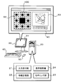
- 12 is an explanatory diagram illustrating an example of a window 90 displayed on the display screen 31 of the display device 30.
- FIG. It is a flowchart which shows an example of the 3D coordinate setting routine performed in the computer 20 of an Example. It is explanatory drawing for demonstrating the correspondence rule in an Example. It is explanatory drawing which shows an example of the table which matches 8 square area
- FIG. 1 is a schematic configuration diagram of a computer 20 as a three-dimensional position specifying apparatus according to an embodiment of the present invention.
- the computer 20 of the embodiment includes a CPU, ROM, RAM, graphic processor (GPU), graphic memory (VRAM), system bus, various interfaces, hard disk drive and flash memory drive (SSD) (not shown).
- the computer is configured as a general-purpose computer including an external storage device or the like, and is used by being connected to a display device 30 such as a liquid crystal display which is a general two-dimensional display, a keyboard 40 or a mouse 50 as an input device, and the like.
- the computer 20 is designated with a two-dimensional position (two-dimensional coordinate) in a two-dimensional space (two-dimensional coordinate system) displayed on the display screen 31 of the display device 30 to specify a three-dimensional space (three-dimensional coordinate system).
- a three-dimensional position designation program that enables designation of a three-dimensional position (three-dimensional coordinates) is installed.
- “2D” is appropriately referred to as “2D”
- “3D” is referred to as “3D”.
- the window 90 When the three-dimensional position designation program is started in the computer 20, a window 90 is displayed on the display screen 31 of the display device 30 as shown in FIGS.
- the window 90 includes a 2D coordinate designation area 92 and a 3D image display area 93.
- the N-th stage Sherpinski carpet 100 which is a fractal obtained by application, is displayed.
- the 3D image display area 93 In the 3D image display area 93, a cubic three-dimensional frame XYZ indicating a three-dimensional space is displayed.
- a location corresponding to the cursor position on the Sherpinski carpet 100 is displayed.
- a point is plotted and displayed at a point (see a part indicated by an arrow in FIG. 2), and a point (hereinafter referred to as “determined point”) Pc indicating a three-dimensional coordinate corresponding to the cursor position in the three-dimensional frame XYZ is fixedly displayed.
- the frame F is erased. Note that the three-dimensional frame XYZ, the fixed point Pc, and the like can be moved in the 3D image display area 93 by a user operation.
- the window 90 includes buttons 95 such as “LINE”, “CURVE”, “PLANE”, “CURVED SURFACE”, “CIRCLE”, “SPHERE”, “delete”, “copy”, “tool”, “save”. Is arranged.
- the “LINE” button is used to instruct the setting of a straight line or a broken line passing through a plurality of fixed points Pc existing in the three-dimensional frame XYZ.
- the “CURVE” button is used to instruct the setting of a curve determined from three or more fixed points Pc existing in the three-dimensional frame XYZ.
- the “PLANE” button is used to instruct the setting of a plane determined from three or more fixed points Pc existing in the three-dimensional frame XYZ.
- the “CURVED SURFACE” button is used to instruct the setting of a curved surface determined from four or more fixed points Pc existing in the three-dimensional frame XYZ.
- the “CIRCLE” button is used to instruct the setting of a circle (plane) centered on one of the two fixed points Pc existing in the three-dimensional frame XYZ and the other one on the circumference. is there.
- the “SPHERE” button is used to instruct the setting of a spherical surface centered on one of the two fixed points Pc existing in the three-dimensional frame XYZ and the other one on the spherical surface.
- the “delete” button is used to instruct the deletion of the fixed point Pc, line, surface, etc.
- the “copy” button is used to instruct copying of a figure such as a line or a surface existing in the three-dimensional frame XYZ.
- the “tool” button is capable of instructing execution of an option prepared in advance (for example, setting of a vector field described later).
- the “save” button is used to instruct the saving of the three-dimensional shape displayed in the three-dimensional frame XYZ.
- the input receiving unit 21, the information storage unit (RAM and external storage device) 22, the modeling unit 23, the display control unit 24, and the like are constructed as functional blocks in cooperation with one or both of the dimension position specifying programs.
- the input reception unit 21 receives a 2D position designated by the user, that is, a cursor position in the 2D coordinate designation area 92 (xy coordinates in pixel units in the two-dimensional absolute coordinate system set on the display screen 31) from the mouse 50 and the keyboard 40.
- the input of information is received, and the received information is stored in the information storage unit (RAM) 22.
- the modeling unit 23 calculates the 3D coordinates in the three-dimensional frame XYZ corresponding to the cursor position based on the cursor position in the 2D coordinate designation area 92 designated by the user, or operates the button 95 on the window 90 described above. Set lines, surfaces, etc. accordingly.
- the display control unit 24 executes image display processing (including rendering) in accordance with a user operation in the 2D coordinate designation area 92 and the 3D image display area 93.
- FIG. 3 is a flowchart illustrating an example of a 3D coordinate setting routine executed in the computer 20 according to the embodiment.
- this 3D coordinate setting routine when the three-dimensional position designation program is started and the cursor is placed on the square area on the Sherpinski carpet 100 displayed in the 2D coordinate designation area 92, for example, the modeling unit 23 of the computer 20 is used. Is repeatedly executed.
- the modeling unit 23 converts the cursor position (xy coordinates in pixel units on the display screen 31) in the 2D coordinate specification area 92 specified by the user, thereby converting the 2D coordinate specification area.
- 2D coordinates (x, y) in the two-dimensional absolute coordinate system set to 92 are acquired (step S100).
- the modeling unit 23 performs predetermined coordinates (x (n), y (n)), coordinates (x ′′ (n), y ′′ (n)), and coordinates (X ′ (n), Y ′ (n), Z ′ (n)) are initialized according to the following equations (1) to (3), respectively (step S110).
- n is a control variable. Then, the modeling unit 23 executes a coordinate conversion process for converting 2D coordinates (x, y) into 3D coordinates (X, Y, Z) in the three-dimensional frame XYZ using a table based on a predetermined correspondence rule. (Step S120).
- a predetermined base point for example, the vertex at the lower left in the figure
- a three-dimensional one-stroke path that proceeds in the x direction ⁇ z direction ⁇ ⁇ x direction ⁇ y direction ⁇ x direction ⁇ ⁇ z direction ⁇ ⁇ x direction ⁇ ⁇ y direction from the lower left apex) is predetermined.
- the correspondence rule is that the eight-dimensional area of the Sherpinski carpet in the first stage is applied to the 3D stroke for 2 ⁇ 2 ⁇ 2 voxels according to the order in the path of the 2D stroke stroke. It is supposed to be assigned so as to follow the path of writing.
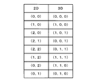
- the table shown in FIG. 5 is prepared in order to apply the correspondence rule to the coordinate conversion process.
- 2 N constituting the voxel space square region Sierpinski Carpet of the N stage corresponding to the 2D coordinates (x, y) as shown in FIGS. 6 and 7 It can be associated with any one of ⁇ 2 N ⁇ 2 N voxels.
- the value N is appropriately referred to as “resolution” of the Sherpinski carpet or voxel space.
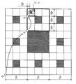
- 6 and 7 exemplify the case where the resolution N of the Sherpinski carpet 100 displayed in the 2D coordinate designation area 92 is a value 3, and the cursor is at the position shown in FIG.
- the 2D coordinates (x, y) are obtained from the correspondence rule shown in FIG. It will be included in the sixth square area of the first stage Sherpinski carpet.
- the 2D coordinates (x, y) are as described above according to the correspondence rule shown in FIG.
- the seventh square area is included. Therefore, if the relative coordinates (the origin O 1 is (0, 0)) of the sixth square area of the first stage Sherpinski carpet of the origin O 2 of the seventh square area are obtained, by using the table of FIG.
- 3D coordinates (X, Y, Z) in the three-dimensional frame XYZ corresponding to the 2D coordinates (x, y) can be obtained by adding the relative coordinates of the voxels in the respective steps.
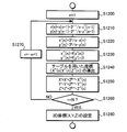
- FIG. 8 is a flowchart showing an example of the coordinate conversion process in step S120 for converting 2D coordinates (x, y) into 3D coordinates (X, Y, Z) in the three-dimensional frame XYZ by the above-described procedure.
- the modeling unit 23 sets the variable n to the value 1 (step S1200), and the coordinates (x (n), y (n)) are expressed by the following formula ( Set according to 4) and (5) (step S1210).
- “s” indicates the length (number of pixels) of one side of the Sherpinski carpet 100 displayed in the 2D coordinate designation area 92 (see FIG. 2).
- values x ′ (n) and y ′ (n) are calculated from the following equations (6) and (7) using the set coordinates (x (n), y (n)) (step S1220).
- the coordinates (x ′′ (n), y ′′ (n)) are set by truncating the decimal places of x ′ (n) and y ′ (n), respectively (step S1230).
- the coordinates (x (n), y ( n)) is, 2D coordinates relative to the origin O n square area corresponding to the Sierpinski Carpet of 2D coordinates of the n steps (x, y) (x, y ) Is the absolute coordinate of the point.
- the coordinates (x ′′ (n), y ′′ (n)) obtained through the processes of steps S1210 and S1220 are square areas corresponding to the 2D coordinates (x, y) of the n-th Sherpinski carpet. indicating the origin O n (n-1) th stage of the Sierpinski carpet of 2D coordinates (x, y) of the relative coordinates in the square region corresponding to.
- the coordinates (x ′′ (n), y ′′ (n)) are obtained as any of the two-dimensional relative coordinates in the table of FIG. 5, and therefore the coordinates (x ′′ (n ), Y ′′ (n)) corresponding to the three-dimensional relative coordinates (X ′′ (n), Y ′′ (n), Z ′′ (n)), that is, 2D coordinates (x, y) in the voxel space of resolution n.
- the relative coordinates in the voxel corresponding to the 2D coordinate (x, y) in the voxel space with the resolution n ⁇ 1 of the voxel corresponding to can be derived (step S1240), thus the coordinates (X ′′ (n), Y ′′.
- 2D coordinates (x, y) are obtained in a voxel space composed of 2 n ⁇ 2 n ⁇ 2 n voxels according to the following equations (8) to (10).
- step S1250 it is determined whether or not the variable n matches the value N (the resolution of the Sherpinski carpet 100) (step S1260). If the variable n is less than the value N, the variable n is set. Increment (step S1270), the processing of steps S1210 to S1250 is executed again. In step S1260, when the variable n matches the value N, the 3D coordinates (X, Y, Z) corresponding to the 2D coordinates (x, y) based on the coordinates (X ′, Y ′, Z ′). And is stored in the information storage unit 22 (RAM) (step S1280).
- N the resolution of the Sherpinski carpet 100
- step S1280 of the embodiment 2D coordinates are obtained in a voxel space composed of 2 N ⁇ 2 N ⁇ 2 N voxels obtained from the coordinates (X ′, Y ′, Z ′) according to the following equations (11) to (13).
- the coordinates of the center of the voxel corresponding to (x, y) are set as 3D coordinates (X, Y, Z).
- “S” indicates the length (number of pixels) of one side of the three-dimensional frame XYZ displayed in the 3D image display area 93 (see FIG. 2).
- the modeling unit 23 causes the cubic frame F (eight vertices and vertices) having a predetermined size centered on the 3D coordinates (X, Y, Z). (12 straight lines connecting each other) and the set information are stored in the information storage unit 22 (RAM) (step S130), and the point P and the frame F corresponding to the set 3D coordinates (X, Y, Z) Is displayed to the display control unit 24 (step S140).
- the display control unit 24 that has received the image display command from the modeling unit 23 reads information on the 3D coordinates (X, Y, Z), the frame F, and the like from the information storage unit 22 so that the point P and the frame F have 3
- the image display process is executed so that the 3D image display area 93 is projected and displayed together with the dimension frame XYZ, the existing fixed point Pc, and the like.
- the modeling unit 23 determines whether or not the 2D position determination process has been executed by the user (step S150). If the 2D position determination process has not been executed, the modeling unit 23 again performs step S100. The subsequent processing is executed.
- the modeling unit 23 uses the 3D coordinates (X, Y, Z) set in step S120 (S1280) as the coordinates of the new determined point Pc.
- the display control unit 24 After storing the data in the storage unit 22 (RAM) (step S160), the display control unit 24 is instructed to display an image such as a fixed point Pc (step S170), and the processing after step S100 is executed again.
- the display control unit 24 Upon receiving the image display command from the modeling unit 23, the display control unit 24 reads the 3D coordinates (X, Y, Z) and the like of the fixed point Pc from the information storage unit 22, and the new fixed point Pc is displayed in the three-dimensional frame XYZ.
- the image display process is executed so that it is projected and displayed on the 3D image display area 93 together with the existing fixed point Pc and the like.
- the pre-determined point P and the definite point Pc may be displayed in the 3D image display area 93 by changing the color or shape in consideration of distinguishability.
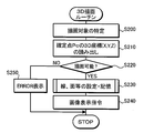
- FIG. 9 is a flowchart illustrating an example of a 3D drawing routine executed by the computer 20 according to the embodiment.
- the 3D drawing routine includes buttons 95 such as “LINE”, “CURVE”, “PLANE”, “CURVED SURFACE”, “CIRCLE”, and “SPHERE” on the window 90 in a state in which the three-dimensional position designation program is activated. Is clicked, it is executed by the modeling unit 23 of the computer 20.
- the modeling unit 23 determines that the button 95 clicked by the user is one of “LINE”, “CURVE”, “PLANE”, “CURVED SURFACE”, “CIRCLE”, and “SPHERE”. To determine the drawing target corresponding to the button 95 clicked by the user (step S200). Next, the 3D coordinates (X, Y, Z) of all the fixed points Pc are read from the information storage unit 22 (step S210), and it is determined whether or not the drawing target specified by the user can be drawn (step S220). ). In step S220, it is basically determined whether or not the drawing target can be drawn by comparing the minimum number of fixed points Pc determined for each drawing target with the number of existing fixed points Pc. .
- step S220 determines, for example, “3D position. Instruct the display control unit 24 to display an “ERROR” message on the display screen 31 (step S250).
- step S220 determines the straight line specified by the user based on the 3D coordinates (X, Y, Z) of the fixed point Pc, A polygonal line, a curve, a plane, a curved surface, a circle, or a sphere is set, and the set information is stored in the information storage unit 22 (step S230). Then, the modeling unit 23 instructs the display control unit 24 to display an image of the set line or surface (step S240), and ends this routine.
- the display control unit 24 Upon receiving the image display command from the modeling unit 23, the display control unit 24 displays the image so that the set line or surface is projected and displayed on the 3D image display area 93 together with the 3D frame XYZ, the existing fixed point Pc, or the like. Execute the process.
- the two definite points Pc can be expressed as (X 0 , Y 0 , Z 0 ) and (X 1 , Y 1 , Z 1 ), respectively.
- a straight line passing through these two fixed points Pc can be defined as in the following equation (14).
- parametrics such as a Bezier curve and a NURBS curve can be used.
- N definite points Pc exist, if the parameter is t and the order of the curve is n, the 3D coordinate P (t) on the Bezier curve is expressed by the following equation (15). Can be defined.
- N definite points Pc when N definite points Pc exist, if f i, k (t) is a B-spline basis function, w i is a weight, and the order of the curve is n, 3D on the NURBS curve
- the coordinate P (t) can be defined as the following equation (16).
- any one of the three definite points Pc is set to (X 0 , Y 0 , Z 0 ), and a normal vector determined from the three definite points Pc is (a , B, c), a plane determined from the three definite points Pc can be defined as the following equation (17).
- a parametric curved surface such as a Bezier curved surface defined by the following equation (18) or a NURBS curved surface defined by the following equation (19) can be used (however, In equations (18) and (19), “u” and “v” are parameters.)
- the computer 20 in which the three-dimensional position designation program of the embodiment is installed is connected to the display device 30 capable of displaying an image on the display screen 31, and the three-dimensional position designation program is started.
- the display control unit 24 causes the N-th stage Shelpinski carpet 100 to be displayed in the 2D coordinate designation area 92 as a two-dimensional space on the display screen 31.
- the 2D position xy coordinates in pixel units
- any square area is designated on the N-th stage Sherpinski carpet 100 displayed in the 2D coordinate designation area 92
- the depth is not designated.
- the position in the voxel space with the resolution N of one voxel corresponding to the 2D position (2D coordinates (x, y)) designated on the Sherpinski carpet 100 is obtained by simple arrangement calculation. Then, 3D coordinates (X, Y, Z) that are three-dimensional positions in the three-dimensional frame XYZ as a three-dimensional space are acquired from the position of the one voxel in the voxel space, and the three-dimensional coordinates (X, Y, Z, A point P indicating Z) is plotted and displayed in the 3D image display area 93 on the display screen 31.
- the computer 20 in which the three-dimensional position specifying program is installed is used, the 3D coordinates (3D positions) in the three-dimensional frame XYZ are reduced while the calculation load is reduced by specifying the 2D positions in the 2D coordinate specifying area 92. Can be specified easily and accurately. Further, the computer 20 can designate the 2D position, that is, the square area of the N-th stage Shelpinski carpet 100 with reference to the point P plotted in the 3D image display area 93, so that the 3D frame is displayed. It becomes possible to easily specify desired 3D coordinates in XYZ.
- the 3D image display area 93 displays a cubic frame F based on voxels of a predetermined size around the point P corresponding to the 3D coordinates until the 2D position determination process is executed. It is possible to easily grasp where in the three-dimensional frame XYZ the 3D coordinates (point P) corresponding to the 2D position designated in the coordinate designation area 92 are located.
- the correspondence rule applied to the computer 20 of the embodiment is the correspondence between the eight square areas constituting the first Shelpinsky carpet and the 2 ⁇ 2 ⁇ 2 voxels constituting one volume. It defines the relationship. Accordingly, the 2D coordinates (x, y) of the n-1th Sherpinski carpet in the square region corresponding to the 2D coordinates (x, y) of the Shelpinsky carpet of the nth stage (1 ⁇ n ⁇ N). From the relative coordinates (x ′′ (n), y ′′ (n)) in the square region corresponding to y) and the table of FIG.
- 2D coordinates (x, The relative coordinates (X ′′ (n), Y ′′ (n), Z ′′ (n) in the voxel corresponding to the 2D coordinate (x, y) in the voxel space of resolution N n ⁇ 1 of the voxel corresponding to y) If the obtained n relative coordinates (X ′′ (n), Y ′′ (n), Z ′′ (n)) are used, 2D coordinates (x, y) are supported. It is possible to acquire 3D coordinates (X, Y, Z) in the 3D frame XYZ To become.
- the carpet 100 in the 2D coordinate designation area 92 as a fractal expansion of the designated square area, the user can gradually set desired 3D coordinates (X, Y, Z) in the 3D frame XYZ. It can be specified.
- a table that associates all square areas of the N-th stage Sherpinski carpet with 2 N ⁇ 2 N ⁇ 2 N voxels constituting the voxel space may be prepared in advance. Good.
- the correspondence rule applied to the computer 20 of the embodiment is 2 ⁇ 2 according to the order of the eight square areas of the first-stage Sherpinski carpet in accordance with the order on the one-stroke path defined for them.
- This is a rule that assigns two voxels to follow a one-stroke path.
- the adjacent relationship between at least two square regions in the N-th stage Sherpinski carpet 100 can be maintained in a voxel space (3D frame XYZ) composed of 2 N ⁇ 2 N ⁇ 2 N voxels. Therefore, the proximity relationship of the square areas on the Sherpinski carpet 100 can be maintained relatively well even in the three-dimensional frame XYZ.
- the correspondence rule is that the 2 ⁇ 2 ⁇ 2 voxels constituting one volume in the three-dimensional space and the eight square areas constituting the first stage Sherpinski carpet in the two-dimensional space. Any correspondence relationship may be defined as long as it defines a correspondence relationship with the above.
- the modeling unit 23 constructed in the computer 20 of the embodiment passes through the plurality of 3D coordinates in response to the click of the “LINE” button when a plurality of 3D coordinates are designated in the three-dimensional frame XYZ.
- a straight line or a broken line can be set.
- the modeling unit 23 can set a curve determined from the three or more 3D coordinates in response to a click on the “CURVE” button.
- the modeling unit 23 can set a plane determined from the three or more 3D coordinates in response to a click on “PLANE”.
- the modeling unit 23 can set a curved surface determined from three or more 3D coordinates in response to a click of the “CURVED SURFACE” button when four or more 3D coordinates are specified in the three-dimensional frame XYZ. is there.
- the modeling unit 23 makes a circle or a sphere based on the two 3D coordinates in response to the click of the “CIRCLE” button or the “SPHERE” button. Can be set. Therefore, if the computer 20 in which the three-dimensional position designation program of the embodiment is installed, various three-dimensional shapes can be drawn and designed.
- the setting procedure of the lines and planes is not limited to the procedure shown in FIG. 9, and after the user clicks the button 95, the required number of 3D positions (the square area of the Sherpinski carpet 100) are designated. The setting of the line and the surface may be executed after the process is performed.
- the display device 30 may be configured as a so-called liquid crystal tablet including a tablet capable of detecting absolute coordinates on the display screen 31 designated by a stylus (not shown).
- a so-called dual monitor may be used as the display device 30, and the 2D coordinate designation region 92 may be displayed on one of the two display devices 30 and the 3D image display region 93 may be displayed on the other.
- the N-th stage Sherpinski carpet 100 is directly associated with the 2D coordinate designation area 92 as a two-dimensional space, but the present invention is not limited to this.
- the N-th stage Sherpinski carpet 100 is indirectly connected through a further 2D coordinate conversion process so that the correspondence between the 2D coordinate designation area 92 and the three-dimensional frame 93 becomes more intuitive and easy to understand. May be associated.
- a frame (image) based on the voxel corresponding to the square area to which the blank area belongs is displayed in the 3D image display area 93
- Information related to the square area to which the blank area belongs may be displayed in the 2D coordinate designation area 92 or the 3D image display area 93.
- “Voxel” in the above embodiment basically means a simple cube having no so-called voxel value, but a voxel value is assigned to each voxel in a voxel space associated with a three-dimensional space. Also good. Thus, by specifying a two-dimensional position in the two-dimensional space, it becomes possible to access a voxel value at a three-dimensional position corresponding to the two-dimensional position. As an application example for giving a voxel value to a voxel in this way, there is a color picker that is an interface that allows a user to select an arbitrary color in photo processing software, paint software, or the like.
- the color is expressed by three components of R (red), G (green), and B (blue).
- R (R, G, B) (0, 0, 0) is black
- ( R, G, B) (255, 0, 0) is red
- the intensity of each color component is expressed as a parameter of 256 gradations. It is common to be done. Therefore, on the computer, the color space can be regarded as a three-dimensional space composed of RGB three axes.
- the YUV format that expresses the color by the three information of the luminance signal (Y), the difference between the luminance signal and the blue component (U), and the difference between the luminance signal and the red component (V), the luminance (brightness: Y), and the hue
- a color picker similar to that in the RGB format can be configured using the present invention.
- the square area of the Sherpinski carpet with a predetermined resolution is associated with the voxels (stored product information) constituting the voxel space in advance, or the correspondence rules as described above are used.
- the square area of the Sherpinski carpet with a predetermined resolution is associated with the voxels (stored product information) constituting the voxel space in advance, or the correspondence rules as described above are used.
- the correspondence rules as described above are used.
- the management software of a three-dimensional warehouse or a three-dimensional parking lot it is conceivable to arrange the inventory information and the warehousing situation in a three-dimensional manner on the management screen.
- the square area of the Sherpinsky carpet having a predetermined resolution is associated with the voxels (which store inventory information and warehousing information) constituting the voxel space in advance, or as described above.
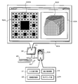
- FIG. 10 is a schematic configuration diagram of a computer 20A as a voxel modeling apparatus in which the voxel modeling program according to the present invention is installed.
- the same reference numerals are assigned to the same elements as the elements described so far, and a duplicate description is omitted.
- window 90 ⁇ / b> A is displayed on the display screen 31 of the display device 30.
- Window 90A includes a 2D coordinate designation area 92A and a 3D image display area 93A.
- the N-th stage Shelpinsky carpet 100A is displayed, and when the user selects any square area of the Sherpinski carpet 100A, for example, the square The area appears to be filled.
- the 3D image display area 93A includes a 2D position (xy coordinates in pixel units) designated (selected) by the user on the Sherpinsky carpet 100A displayed in the 2D coordinate designation area 92A, that is, any square area.
- a 3D image 300 showing the three-dimensional shape set by the modeling unit 23A based on the voxels corresponding to is displayed.
- the modeling unit 23 uses the above-described correspondence rule (table), and 2 N ⁇ 2 N ⁇ 2 of one voxel corresponding to the square area designated on the Sherpinski carpet 100.
- a position in a voxel space made up of N voxels is acquired, and the three-dimensional shape is set so as to cut out the cube by erasing the voxel at the acquired position.
- the computer 20A in which the voxel modeling program is installed by providing a voxel value to each voxel, unlike the polygon modeling, the density inside the shape as well as the surface of the three-dimensional shape. It is possible to model even internal data.
- the three-dimensional shape obtained by voxel modeling does not have a smooth surface. For example, see the marching cube method (Lorensen WE, Cline HE, "Marching Cubes: A High Resolution 3D Surface Construction Algorithm”) ) Can be used to approximate a three-dimensional surface to a smooth one. In the example of FIG.
- the three-dimensional shape is set by erasing the voxel corresponding to the square area designated on the Sherpinski carpet 100 from the voxel space.
- the present invention is not limited to this. . That is, the three-dimensional shape may be set so that voxels corresponding to the designated square area on the Sherpinski carpet 100 are stacked, that is, as a set of voxels corresponding to the designated square area.
- the present invention can be used in the information processing field that requires designation of a three-dimensional position in a three-dimensional space and representation of a three-dimensional shape.
Landscapes
- Physics & Mathematics (AREA)
- Engineering & Computer Science (AREA)
- Computer Graphics (AREA)
- Geometry (AREA)
- Software Systems (AREA)
- General Physics & Mathematics (AREA)
- Theoretical Computer Science (AREA)
- Processing Or Creating Images (AREA)
- Controls And Circuits For Display Device (AREA)
- Position Input By Displaying (AREA)
Applications Claiming Priority (2)
| Application Number | Priority Date | Filing Date | Title |
|---|---|---|---|
| JP2008-231398 | 2008-09-09 | ||
| JP2008231398A JP5248958B2 (ja) | 2008-09-09 | 2008-09-09 | 3次元位置指定装置、3次元位置指定用プログラム、ボクセルモデリング装置およびボクセルモデリング用プログラム |
Publications (1)
| Publication Number | Publication Date |
|---|---|
| WO2010029953A1 true WO2010029953A1 (ja) | 2010-03-18 |
Family
ID=42005206
Family Applications (1)
| Application Number | Title | Priority Date | Filing Date |
|---|---|---|---|
| PCT/JP2009/065770 Ceased WO2010029953A1 (ja) | 2008-09-09 | 2009-09-09 | 3次元位置指定装置、3次元位置指定方法および3次元位置指定用プログラム、ならびにボクセルモデリング装置、ボクセルモデリング方法およびボクセルモデリング用プログラム |
Country Status (2)
| Country | Link |
|---|---|
| JP (1) | JP5248958B2 (enExample) |
| WO (1) | WO2010029953A1 (enExample) |
Cited By (2)
| Publication number | Priority date | Publication date | Assignee | Title |
|---|---|---|---|---|
| CN110009729A (zh) * | 2019-03-21 | 2019-07-12 | 深圳点猫科技有限公司 | 一种基于人工智能的三维体素建模方法及系统 |
| CN110021058B (zh) * | 2019-03-21 | 2023-09-26 | 深圳点猫科技有限公司 | 一种便于少儿操作的三维体素建模方法及系统 |
Families Citing this family (1)
| Publication number | Priority date | Publication date | Assignee | Title |
|---|---|---|---|---|
| JP6852298B2 (ja) * | 2015-08-21 | 2021-03-31 | 東亞合成株式会社 | インクジェットインキ用硬化型組成物 |
Citations (1)
| Publication number | Priority date | Publication date | Assignee | Title |
|---|---|---|---|---|
| JPS61169927A (ja) * | 1985-01-23 | 1986-07-31 | Hitachi Ltd | 3次元座標入力方法 |
-
2008
- 2008-09-09 JP JP2008231398A patent/JP5248958B2/ja not_active Expired - Fee Related
-
2009
- 2009-09-09 WO PCT/JP2009/065770 patent/WO2010029953A1/ja not_active Ceased
Patent Citations (1)
| Publication number | Priority date | Publication date | Assignee | Title |
|---|---|---|---|---|
| JPS61169927A (ja) * | 1985-01-23 | 1986-07-31 | Hitachi Ltd | 3次元座標入力方法 |
Non-Patent Citations (2)
| Title |
|---|
| MASAKI IWAMARU ET AL.: "Fractal Zukei o Mochiita Volume Data no 2 Jigen Tenkai ni yoru Kashika Shuho to sono Oyo", JOURNAL OF THE VISUALIZATION SOCIETY OF JAPAN, KASHIKA JOHO ZENKOKU KOENKAI (KUSHIRO 2008) KOEN RONBUNSHU, vol. 28, no. 2, 15 September 2008 (2008-09-15), pages 167 - 168 * |
| MASAKI IWAMARU ET AL.: "Fractal Zukei o Mochiita Volume Data no 2 Jigen Tenkai ni yoru Kashika Shuho", JOURNAL OF THE VISUALIZATION SOCIETY OF JAPAN, vol. 28, no. 1, 1 July 2008 (2008-07-01), pages 75 - 78 * |
Cited By (3)
| Publication number | Priority date | Publication date | Assignee | Title |
|---|---|---|---|---|
| CN110009729A (zh) * | 2019-03-21 | 2019-07-12 | 深圳点猫科技有限公司 | 一种基于人工智能的三维体素建模方法及系统 |
| CN110009729B (zh) * | 2019-03-21 | 2023-07-07 | 深圳点猫科技有限公司 | 一种基于人工智能的三维体素建模方法及系统 |
| CN110021058B (zh) * | 2019-03-21 | 2023-09-26 | 深圳点猫科技有限公司 | 一种便于少儿操作的三维体素建模方法及系统 |
Also Published As
| Publication number | Publication date |
|---|---|
| JP2010066920A (ja) | 2010-03-25 |
| JP5248958B2 (ja) | 2013-07-31 |
Similar Documents
| Publication | Publication Date | Title |
|---|---|---|
| JP7004645B2 (ja) | 中心窩ジオメトリテッセレーション | |
| US20200372602A1 (en) | Scheme for compressing vertex shader output parameters | |
| US8878845B2 (en) | Expandable graphical affordances | |
| CN102947865B (zh) | 用于光线跟踪中的图元相交的系统和方法 | |
| US20130300740A1 (en) | System and Method for Displaying Data Having Spatial Coordinates | |
| CN114375464B (zh) | 使用边界体积表示对虚拟空间中的动态单元进行光线追踪 | |
| US9269195B2 (en) | Methods and apparatus for generating curved extrusions | |
| EP3040946B1 (en) | Viewpoint selection in the rendering of a set of objects | |
| WO2018204029A2 (en) | Three-dimensional digital model ghosting | |
| KR101507776B1 (ko) | 3차원 지도의 외곽선 표현 방법 | |
| JPH07200218A (ja) | グラフィカル・オブジェクトをインターロックする方法及び装置 | |
| JP2006107093A (ja) | 画像処理装置、およびプログラム | |
| JP5248958B2 (ja) | 3次元位置指定装置、3次元位置指定用プログラム、ボクセルモデリング装置およびボクセルモデリング用プログラム | |
| CN111932689B (zh) | 一种采用id像素图的三维对象快速选取方法 | |
| US8334869B1 (en) | Method and apparatus for modeling 3-D shapes from a user drawn curve | |
| JP3522505B2 (ja) | ウィンドウ表示装置 | |
| US20240242437A1 (en) | Computer-aided techniques for designing 3d surfaces based on gradient specifications | |
| US11836333B2 (en) | Computer-implemented method and SDK for rapid rendering of object-oriented environments with enhanced interaction | |
| Sanchez et al. | DirectX 3D graphics programming bible | |
| JP7455546B2 (ja) | 画像処理装置、画像処理方法、及びプログラム | |
| AU2023274149B2 (en) | Method for 3D visualization of sensor data | |
| CN116601662A (zh) | 一种图形处理方法、装置、设备及介质 | |
| KR100848687B1 (ko) | 3차원 그래픽 처리 장치 및 그것의 동작 방법 | |
| JP2002092649A (ja) | 画像処理装置および画像処理方法並びに記録媒体 | |
| JP4585298B2 (ja) | 描画方法及びその装置 |
Legal Events
| Date | Code | Title | Description |
|---|---|---|---|
| 121 | Ep: the epo has been informed by wipo that ep was designated in this application |
Ref document number: 09813099 Country of ref document: EP Kind code of ref document: A1 |
|
| NENP | Non-entry into the national phase |
Ref country code: DE |
|
| 122 | Ep: pct application non-entry in european phase |
Ref document number: 09813099 Country of ref document: EP Kind code of ref document: A1 |