WO2010024403A1 - 中継装置の動作設定方法、中継装置、およびプログラムを記憶した記憶媒体 - Google Patents
中継装置の動作設定方法、中継装置、およびプログラムを記憶した記憶媒体 Download PDFInfo
- Publication number
- WO2010024403A1 WO2010024403A1 PCT/JP2009/065102 JP2009065102W WO2010024403A1 WO 2010024403 A1 WO2010024403 A1 WO 2010024403A1 JP 2009065102 W JP2009065102 W JP 2009065102W WO 2010024403 A1 WO2010024403 A1 WO 2010024403A1
- Authority
- WO
- WIPO (PCT)
- Prior art keywords
- communication
- address
- relay device
- setting
- operation terminal
- Prior art date
- Legal status (The legal status is an assumption and is not a legal conclusion. Google has not performed a legal analysis and makes no representation as to the accuracy of the status listed.)
- Ceased
Links
Images


Classifications
-
- H—ELECTRICITY
- H04—ELECTRIC COMMUNICATION TECHNIQUE
- H04L—TRANSMISSION OF DIGITAL INFORMATION, e.g. TELEGRAPHIC COMMUNICATION
- H04L12/00—Data switching networks
- H04L12/28—Data switching networks characterised by path configuration, e.g. LAN [Local Area Networks] or WAN [Wide Area Networks]
- H04L12/46—Interconnection of networks
- H04L12/4604—LAN interconnection over a backbone network, e.g. Internet, Frame Relay
- H04L12/462—LAN interconnection over a bridge based backbone
- H04L12/4625—Single bridge functionality, e.g. connection of two networks over a single bridge
-
- H—ELECTRICITY
- H04—ELECTRIC COMMUNICATION TECHNIQUE
- H04L—TRANSMISSION OF DIGITAL INFORMATION, e.g. TELEGRAPHIC COMMUNICATION
- H04L12/00—Data switching networks
- H04L12/28—Data switching networks characterised by path configuration, e.g. LAN [Local Area Networks] or WAN [Wide Area Networks]
- H04L12/46—Interconnection of networks
- H04L12/4641—Virtual LANs, VLANs, e.g. virtual private networks [VPN]
-
- H—ELECTRICITY
- H04—ELECTRIC COMMUNICATION TECHNIQUE
- H04L—TRANSMISSION OF DIGITAL INFORMATION, e.g. TELEGRAPHIC COMMUNICATION
- H04L12/00—Data switching networks
- H04L12/66—Arrangements for connecting between networks having differing types of switching systems, e.g. gateways
-
- H—ELECTRICITY
- H04—ELECTRIC COMMUNICATION TECHNIQUE
- H04L—TRANSMISSION OF DIGITAL INFORMATION, e.g. TELEGRAPHIC COMMUNICATION
- H04L41/00—Arrangements for maintenance, administration or management of data switching networks, e.g. of packet switching networks
- H04L41/08—Configuration management of networks or network elements
- H04L41/0803—Configuration setting
- H04L41/0806—Configuration setting for initial configuration or provisioning, e.g. plug-and-play
-
- H—ELECTRICITY
- H04—ELECTRIC COMMUNICATION TECHNIQUE
- H04L—TRANSMISSION OF DIGITAL INFORMATION, e.g. TELEGRAPHIC COMMUNICATION
- H04L61/00—Network arrangements, protocols or services for addressing or naming
- H04L61/09—Mapping addresses
- H04L61/10—Mapping addresses of different types
- H04L61/103—Mapping addresses of different types across network layers, e.g. resolution of network layer into physical layer addresses or address resolution protocol [ARP]
Definitions
- the present invention relates to control for setting operation of a relay device such as a router.
- the operation settings are a communication address (for example, IP (Internet Protocol) address) and subnet mask for identifying the relay device in the network layer, and a default gateway of LAN (Local Area Network) to which the relay device is connected. Is set and stored in the relay device.
- the default gateway is a relay device located at the boundary between the LAN and an external communication network (for example, the Internet), for example, and packets transmitted and received between the communication device in the LAN and the external communication device are always transmitted. It is a relay device that passes through.
- the operation setting for the electronic device is generally realized by inputting various commands for the operation setting by a user interface providing means such as a liquid crystal display or a keyboard.
- a relay device such as a router does not need to input a command during normal operation, it often has no user interface providing means as described above. Therefore, when setting the operation of the relay device, another computer device (for example, a notebook personal computer) provided with a user interface providing means is connected to the relay device as an operation terminal, and this operation terminal is operated. It is common to perform various setting operations.
- the relay device and the operation terminal are connected by a serial cable such as USB (Universal Serial Bus) or RS-232C.
- the relay device and the operation terminal are connected via the LAN.
- relay data communication for example, telnet
- DHCP Dynamic Host Configuration Protocol
- Patent Document 1 a communication address for operation setting (hereinafter referred to as an operation setting address) is stored in advance in the relay device, and data communication using the operation setting address as a destination address is performed in the relay device and the operation terminal. And a technique for setting the operation of the relay device.
- the operation terminal is connected by the serial cable
- a tool such as a serial cable, a USB cable, or a USB serial converter is separately required.
- the mode of using the DHCP server has a problem that it is not possible to cope with the case where the relay server side is set in advance to not use the DHCP server or when the DHCP server is not provided in the LAN.
- the operation setting address there is a problem that it is necessary to check the operation setting address in advance before the operation setting, or the operation setting address cannot be used for some reason.
- the present invention has been made in view of the problems described above, and does not require a tool other than a computer device serving as an operation terminal and a LAN cable even when a DHCP server cannot be used. It is an object of the present invention to provide a technology that makes it possible to perform the operation setting of a relay device without performing a preliminary survey.
- the present invention connects an operation terminal via a LAN cable to a relay device that relays data communication between a plurality of communication devices, and requests an address resolution for any communication address in the network layer. And a process of storing the communication address that is the target of the address resolution request as an operation setting address in the data link layer.
- the operation of the relay device is executed by a terminal and communicated through the communication session.
- the relay device characterized by comprising a third step of performing constant.
- the target address of the address resolution request broadcasted from the operation terminal connected to the relay device that is the target of the operation setting via the LAN cable is set as the operation setting address to the relay device. Is set. Accordingly, the operation terminal can perform data communication with the relay device using the operation setting address as a destination address, and the operation setting of the relay device is performed by the data communication. Therefore, it is not necessary to investigate whether or not an operation setting address is stored in the relay device, and no problem occurs even when DHCP cannot be used. Further, since the operation terminal is connected to the relay device via a LAN cable, there is no need for other tools such as a USB serial converter other than the LAN cable.
- the present invention provides a setting that is referred to when relaying data communication between a communication unit connected to a plurality of communication devices and a communication device connected to the communication unit.
- Storage means for storing information, and when the communication means receives an address resolution request for an arbitrary communication address in the network layer, the communication address of the resolution target is stored in the storage means as an operation setting address And a first session for returning an address resolution response in which the communication address of the device itself is written in the data link layer, and a communication session with the transmission source in response to a request from the transmission source of the address resolution request And a control means for executing a second process for storing the setting information received through the communication session in the storage means.
- the setting information stored in the storage unit of the relay device includes a network layer communication address assigned to the relay device, and the communication unit is connected to the communication device via a LAN cable.
- the control means uses a port VLAN (Virtual Local Area Network) function to switch the plurality of ports to those to which the operation terminal is connected and others.
- the target address of the address resolution request is assigned to the port to which the operation terminal is connected, and the communication address included in the setting information stored in the storage unit is assigned to the other port.
- the communication session between the operation terminal and the relay device is disconnected by resetting the communication address of the port to which the operation terminal is connected to that included in the setting information. Is avoided.
- control means of the relay device is instructed to operate in the operation setting mode when receiving an address resolution request through a port predetermined for operation setting among the plurality of ports. Or when the address resolution request is received in a state where the setting information is not stored in the storage means, the first and second processes are executed. According to such an aspect, it is possible to reliably distinguish an address resolution request transmitted for operation setting from an address resolution request transmitted in a general data communication execution process.
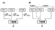
- FIG. 3 is a diagram for explaining a role of a communication I / F unit 120 in the relay device 10. It is a flowchart explaining the flow of the operation
- FIG. 1 is a diagram illustrating a configuration example of a relay device 10 according to an embodiment of the present invention.
- the relay device 10 is a router that relays data communication between a plurality of communication devices (for example, a personal computer (hereinafter referred to as “PC”) or other relay device functioning as a communication terminal), as shown in FIG. It has a control unit 110, a communication interface (hereinafter referred to as “I / F”) unit 120, a storage unit 130, and a bus 140 that mediates data exchange between these components.
- PC personal computer
- I / F communication interface
- the control unit 110 is, for example, a CPU (Central Processing Unit).
- the control unit 110 functions as a control center (control means) that performs various processes according to various programs stored in the storage unit 130 and performs operation control of each unit of the relay device 10. Details of processing executed by the control unit 110 in accordance with various programs will be clarified later.
- the communication I / F unit 120 is, for example, a NIC (Network Interface Card), and serves as a communication unit that connects another communication device and performs data communication with the connection destination.
- the communication I / F unit 120 delivers the data received from the communication device that is the connection destination via each of the ports 120-k to the control unit 110, while the data delivered from the control unit 110 corresponds to the destination. The process of transmitting to the destination via the port 120-k is executed.
- the communication I / F unit 120 is assigned in advance a MAC (Media Control Address) address that is a communication address for identifying the relay device 10 in the data link layer.
- MAC Media Control Address
- the storage unit 130 serves as a storage unit that stores various data and various programs. As illustrated in FIG. 1, the storage unit 130 includes a volatile storage unit 131 and a nonvolatile storage unit 132.
- the volatile storage unit 131 is a volatile memory such as a RAM (Random Access Memory), and is used by the control unit 110 as a work area when executing various programs.
- the non-volatile storage unit 132 is a non-volatile memory such as a FlashROM (Read Only Memory) or a hard disk.
- the nonvolatile storage unit 132 stores a program that causes the control unit 110 to execute processing that significantly indicates the characteristics of the relay device 10 according to the present embodiment, and stores data that is referred to in the execution process.
- the volatile storage unit 131 is a volatile memory such as a RAM (Random Access Memory), and is used by the control unit 110 as a work area when executing various programs.
- the non-volatile storage unit 132 is a non-volatile memory such as a FlashROM
- This setting information 132a is data that defines the operation of the control unit 110 when relaying data communication between a plurality of communication devices connected to the communication I / F unit 120, and is referred to during the execution of the data relay process. Is done.
- the data included in the setting information 132a there is data representing a network layer communication address (IP address) assigned to the relay apparatus 10, a subnet mask, and the like.
- IP address network layer communication address
- examples of programs stored in the nonvolatile storage unit 132 include a relay processing program 132b and a setting work support program 132c.
- the relay processing program 132b is a program for causing the control unit 110 to execute the data relay processing.
- the setting work support program 132c performs communication with other communication devices via the LAN in a manner that clearly shows the features of the present embodiment, and executes processing for writing the setting information 132a in the nonvolatile storage unit 132 to the control unit 110.
- This is a program that supports the operation setting of the relay device 10.
- the relay device 10 has two operation modes, that is, a data relay mode and an operation setting mode, and the relay device 10 is instructed in which of these two operation modes to operate.
- a mode changeover switch is provided (not shown in FIG. 1).
- the control unit 110 reads the relay processing program 132b from the nonvolatile storage unit 132 to the volatile storage unit 131 and executes it to set the operation.
- the setting work support program 132c is read from the nonvolatile storage unit 132 to the volatile storage unit 131 and executed.
- the relay device 10 is provided with a mode changeover switch for switching between the two operation modes described above.
- the relay device 10 may be configured so that it does not operate in the data relay mode unless it is performed. As long as the initial setting is performed at the time of shipment from the factory, the mode change switch is not necessarily essential. The above is the configuration of the relay device 10.
- the relay device 10 does not have user interface providing means (an output device such as a liquid crystal display or an input device such as a keyboard) for inputting data constituting the setting information 132a such as a subnet mask.
- an output device such as a liquid crystal display or an input device such as a keyboard
- a computer device playing the role of an operation terminal during the setting work
- the relay apparatus 10 starts to execute the setting work support program 132c.
- the setting operator performs initial setting of the operation terminal in order to enable data communication with the relay device 10 (FIG. 3: Step SA010).
- the setting operator operates the operation unit (not shown) of the operation terminal, and assigns the network layer communication address and subnet mask (for example, 192.168.100.10/24) assigned to the operation terminal.
- the communication address of the default gateway (for example, 192.168.100.1: the default gateway address) for the LAN to which the relay apparatus 10 is connected is set.
- the default gateway address in the present embodiment is provisionally set in the operation terminal and is used only in the operation setting mode.
- the default gateway address may be an address set in advance on the operation terminal or an arbitrarily set address. Further, when the relay apparatus is operated as a default gateway after the operation setting mode is completed, the default gateway address used in this operation setting mode may be used as it is.
- the setting operator gives the operation terminal an instruction to start telnet communication with the default gateway. Then, the control unit of the operation terminal detects the above instruction (step SA020), and broadcasts an address resolution request (for example, “ARP request”) in which the default gateway address is written in order to obtain the MAC address of the default gateway. (Step SA030).
- the address resolution request transmitted in this way reaches the relay device 10 via the LAN cable.
- the control unit 110 of the relay device 10 operating in the operation setting mode When receiving the address resolution request transmitted from the operation terminal via the communication I / F unit 120, the control unit 110 of the relay device 10 operating in the operation setting mode appropriately sets the subnet mask, and further The IP address to be resolved by the address resolution request is assigned to the communication I / F unit 120 as the communication address of the own device (step SB010), and the address resolution response (for example, “ARP response” in which the MAC address of the communication I / F unit 120 is written. ”) Is returned (step SB020). As a result, the communication address “192.168.100.1” is assigned to the communication I / F unit 120 of the relay apparatus 10 and the MAC address of the relay apparatus 10 is operated as the MAC address of the communication apparatus having the IP address. Reply to the terminal.
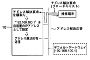
- the relay device 10 intercepts an address resolution request addressed to the default gateway and temporarily impersonates the default gateway.
- the address resolution response sent back from the relay device 10 reaches the operation terminal via the communication cable.
- the subnet mask value set in step SB010 may be determined in advance through experiments.
- the operating terminal that has received the address resolution response sent back as described above uses the MAC address notified in the address resolution response to establish a communication session with the transmission source (that is, the relay device 10). Establish. As a result, the operation terminal and the relay device 10 can perform data communication complying with telnet.
- the setting operator inputs various setting information to be stored in the relay device 10 and a command for instructing the storage to the operation terminal. Then, the setting information and command are transmitted to the operation terminal (step SA040).
- the control unit 110 of the relay apparatus 10 receives the setting information transmitted according to telnet and a command for instructing the storage thereof, stores the setting information according to the command, and stores the setting information in the setting information.
- a process (step SB030) of setting the included communication address in the communication I / F unit 120 is executed. Thereby, the operation setting of the relay device 10 is performed. If the communication address included in the setting information transmitted from the operation terminal is set in the communication I / F unit 120 as described above, the communication session between the operation terminal and the relay device 10 is disconnected. However, since the operation setting for the relay apparatus 10 has been completed, no particular problem occurs even if the communication session is disconnected.
- the control unit 110 starts execution of the relay processing program 132b and stores it in the nonvolatile storage unit 132.
- Data relay processing is executed according to the stored setting information 132a.
- switching from the operation setting mode to the data relay mode is performed by switching the mode switching switch.
- a command for instructing switching of the operation mode is transmitted from the operation terminal to the relay apparatus 10 by telnet communication.
- the control unit 110 may execute a process of automatically switching to the data relay mode when the writing of the setting information to the nonvolatile storage unit 132 is completed.
- the operation setting address is stored in the relay device 10 in advance. There is no need to make a check, and it is not necessary to conduct a preliminary check as to whether or not an operation setting address is set in the relay device 10. Further, there is no need to use a DHCP server, and there is no need for other tools other than a PC and a LAN cable that serve as operation terminals for operation setting work. In other words, according to the present embodiment, even when the DHCP server cannot be used, a tool other than the computer device serving as the operation terminal and the LAN cable is not required, and the relay device is not subjected to any preliminary investigation. There is an effect that operation setting can be performed.
- the IP address of the default gateway for the LAN to which the relay device 10 is connected is used as the communication address temporarily assigned to the relay device 10 for operation setting.
- the IP address of the device may be used, or may not match any of the IP addresses of the communication devices connected to the LAN. That is, it is possible to use an arbitrary IP address (which must be different from the communication address assigned to the operation terminal) as the communication address temporarily assigned to the relay device 10 for operation setting. .
- an address resolution request for resolving the IP address of the default gateway is sent to the operation terminal.
- An address resolution request may be transmitted when an instruction is given to start communication conforming to another communication protocol such as Transfer Protocol (HTTP) or Hypertext Transfer Protocol (HTTP). The user may be instructed directly.
- HTTP Transfer Protocol
- HTTP Hypertext Transfer Protocol
- the control unit 110 when the operation in the operation setting mode is instructed, the control unit 110 starts to execute the setting work support program 132c, and the setting support process (that is, the setting work support program 132c (that is, The control unit 110 executes a process of intercepting an address resolution request and performing data communication for operation setting while pretending to be the destination.
- the execution of the setting support process may be started. Specifically, any one of a plurality of ports included in the communication I / F unit 120 is determined in advance as an operation setting port, and when the address resolution request is received through the operation setting port, the setting support processing is performed. The execution of is started.
- an address resolution request is received in a state where no operation setting is made (that is, a state where the setting information 132a is not stored in the nonvolatile storage unit 132), or when DHCP cannot be used (relay device 10).
- the execution of the setting support process may be started. In short, as long as it is a mode that can distinguish between an address resolution request that is transmitted and received in a general data communication execution process and an address resolution request that is transmitted for operation setting, it is any mode. May be.
- the port VLAN function allows a plurality of ports provided in the communication I / F unit 120 to be connected to an operation terminal and other
- the target address of the address resolution request is assigned to the port to which the operation terminal is connected, while the communication address included in the setting information transmitted from the operation terminal is assigned to the other port. May be.
- FIG. 2B illustrates a case where VLAN-1 is formed by PC-1 and relay apparatus 10, and VLAN-2 is formed by PC-2 to PC-N and relay apparatus 10.
- FIG. 2B when a communication message is broadcast from PC-2, the communication message is transferred to other communication devices in VLAN-2 except for PC-2. Communication control is performed such that the data is not transferred to 1. Similarly, even if a communication message is broadcast from PC-1 in the example shown in FIG. 2B, the communication message is not transferred to the VLAN-2 side.
- the setting work support program 132c for causing the control unit 110 of the relay apparatus 10 to implement the operation setting method according to the present invention is stored in the nonvolatile storage unit 132 in advance.
- the above program may be distributed by writing it on a computer-readable recording medium such as a CD-ROM (Compact Disk-Read Memory), or distributed by downloading via a telecommunication line such as the Internet. You may do it.
- the setting work support program distributed in this way is stored in a general relay device, and the control unit is operated according to the setting work support program, whereby the general relay device and the relay device according to the present invention are connected. It becomes possible to give the same function.
Landscapes
- Engineering & Computer Science (AREA)
- Computer Networks & Wireless Communication (AREA)
- Signal Processing (AREA)
- Computer Security & Cryptography (AREA)
- Small-Scale Networks (AREA)
- Computer And Data Communications (AREA)
Abstract
動作設定の対象である中継装置に通信ケーブルを介して操作端末を接続し、任意のIPアドレスを対象とするアドレス解決要求をその操作端末にブロードキャスト送信させる。一方、中継装置には、そのアドレス解決要求の対象アドレスを自装置の通信アドレスとして記憶し、自装置のMACアドレスを操作端末に返信する処理を実行させる。このようにして返信されるMACアドレスを用いて中継装置との間に通信セッションを確立し、telnetによる動作設定を行う処理を操作端末に実行させる。
Description
本発明は、ルータなどの中継装置の動作設定を行う制御に関する。
ルータなどの中継装置においては、その本来の機能を発揮できるようにするために、所定の動作設定を行っておくことが必要である。ここで、動作設定とは、ネットワーク層にてその中継装置を識別する通信アドレス(例えば、IP(Internet Protocol)アドレス)やサブネットマスク、その中継装置が接続されるLAN(Local Area Network)のデフォルトゲートウェイの通信アドレスをその中継装置に設定し記憶させることである。なお、デフォルトゲートウェイとは、例えばLANと外部の通信網(例えば、インターネット)との境界に位置する中継装置であり、LAN内の通信装置と外部の通信装置との間で送受信されるパケットが必ず通過する中継装置のことである。
ところで、電子機器に対する動作設定は、液晶ディスプレイやキーボードなどのユーザインタフェース提供手段により、動作設定のための各種コマンドを入力することで実現されることが一般的である。しかし、ルータなどの中継装置は、通常稼動時にはコマンド入力を行う必要がないため、上記のようなユーザインタフェース提供手段を備えていない場合が多い。そこで、中継装置の動作設定を行う際には、ユーザインタフェース提供手段を備えた他のコンピュータ装置(例えば、ノート型パーソナルコンピュータ)を操作端末としてその中継装置に接続し、この操作端末を操作して各種設定作業を行うことが一般的である。
中継装置に操作端末を接続する際の具体的な手法としては種々のものが考えられる。第1に、USB(Universal Serial Bus)やRS-232Cなどのシリアルケーブルにより中継装置と操作端末とを接続する態様である。第2に、LANを介して中継装置と操作端末とを接続する態様である。例えば、LANを介して接続する場合には、そのLANに設けられているDHCP(Dynamic Host Configuration Protocol)サーバにより中継装置や操作端末に割り当てられる通信アドレスを利用したデータ通信(例えば、telnet)を中継装置と操作端末に行わせ、中継装置の動作設定を行うことができる。また、特許文献1には、中継装置に動作設定用の通信アドレス(以下、動作設定用アドレス)を予め記憶させておき、その動作設定用アドレスを宛先アドレスとしたデータ通信を中継装置と操作端末とに行わせてその中継装置の動作設定を行う技術が開示されている。
しかし、シリアルケーブルにより操作端末を接続する態様では、シリアルケーブルやUSBケーブル、USBシリアル変換器などの道具が別途必要になるといった問題がある。これに対して、LANを介して接続する態様の場合は、他の道具が必要になることはないものの以下のような問題が生じ得る。すなわち、DHCPサーバを利用する態様には、中継装置側で予めDHCPサーバを利用しない旨の設定が為されている場合や、LANにDHCPサーバが設けられていない場合に対処できないといった問題がある。また、動作設定用アドレスを利用する態様の場合には、動作設定に先立ってその動作設定用アドレスを事前に調べておく必要があるといった問題や、何らかの理由によりその動作設定用アドレスを使用できない場合に動作設定を行うことができないといった問題がある。
本発明は、以上に説明した課題に鑑みて為されたものであり、DHCPサーバを利用できない場合であっても、操作端末となるコンピュータ装置とLANケーブル以外の道具を必要とせず、かつ、何らの事前調査を行うことなく中継装置の動作設定を行うことを可能にする技術を提供することを目的とする。
本発明は、以上に説明した課題に鑑みて為されたものであり、DHCPサーバを利用できない場合であっても、操作端末となるコンピュータ装置とLANケーブル以外の道具を必要とせず、かつ、何らの事前調査を行うことなく中継装置の動作設定を行うことを可能にする技術を提供することを目的とする。
上記課題を解決するために本発明は、複数の通信装置間のデータ通信を中継する中継装置にLANケーブルを介して操作端末を接続し、ネットワーク層における任意の通信アドレスを対象とするアドレス解決要求を前記操作端末にブロードキャスト送信させる第1のステップと、前記アドレス解決要求の対象となる通信アドレスを動作設定用アドレスとして記憶する処理を前記中継装置に実行させるとともに、データリンク層における自装置の通信アドレスを書き込んだアドレス解決応答を返信する処理を前記中継装置に実行させる第2のステップと、前記アドレス解決応答の受信を契機として、前記中継装置との間に通信セッションを確立する処理を前記操作端末に実行させ、その通信セッションを介した通信により前記中継装置の動作設定を行う第3のステップとを含むことを特徴とする中継装置の動作設定方法、を提供する。
このような動作設定方法によれば、動作設定の対象となる中継装置にLANケーブルを介して接続される操作端末からブロードキャスト送信されるアドレス解決要求の対象アドレスが動作設定用アドレスとしてその中継装置に設定される。これにより、上記操作端末は、動作設定用アドレスを宛先アドレスとして上記中継装置とデータ通信を行うことが可能になり、そのデータ通信により上記中継装置の動作設定が行われる。したがって、上記中継装置に動作設定用アドレスが記憶されているか否かなどの調査を行う必要はなく、また、DHCPを利用できない場合であっても何ら問題は生じない。また、操作端末はLANケーブルを介して中継装置に接続されるため、そのLANケーブル以外にUSBシリアル変換器などの他の道具が必要になることも無い。
また、上記動作設定方法を可能にするために本発明は、複数の通信装置が接続される通信手段と、前記通信手段に接続される通信装置間のデータ通信を中継する際に参照される設定情報が格納される記憶手段と、ネットワーク層における任意の通信アドレスを対象とするアドレス解決要求を前記通信手段により受信した場合に、その解決対象の通信アドレスを動作設定用アドレスとして前記記憶手段に記憶するとともに、データリンク層における自装置の通信アドレスを書き込んだアドレス解決応答を返信する第1の処理、および、前記アドレス解決要求の送信元からの要求に応じて当該送信元との間に通信セッションを確立し、その通信セッションを介して受信した設定情報を前記記憶手段に格納する第2の処理を実行する制御手段とを有することを特徴とする中継装置や、上記制御手段が実行する第1および第2の処理をコンピュータ装置に実行させることを特徴とするプログラムを記憶する記憶媒体、を提供する。
より好ましい態様においては、前記中継装置の記憶手段に格納される設定情報には、その中継装置に割り当てるネットワーク層の通信アドレスが含まれているとともに、前記通信手段は、LANケーブルを介して通信装置が1台ずつ接続される複数のポートを有しており、前記制御手段は、ポートVLAN(Virtual Local Area Network)機能により、前記複数のポートを前記操作端末が接続されるものとその他のものに分類し、前記操作端末が接続されているポートには前記アドレス解決要求の対象アドレスを割り当てる一方、その他のポートには前記記憶手段に格納されている設定情報に含まれる通信アドレスを割り当てることを特徴とする。このような態様によれば、操作端末が接続されているポートの通信アドレスが上記設定情報に含まれるものに再設定されることにより、その操作端末と中継装置との間の通信セッションが切断されることが回避される。
さらに好ましい態様においては、前記中継装置の制御手段は、前記複数のポートのうち動作設定用に予め定められたポートを介してアドレス解決要求を受信した場合、動作設定モードでの作動を指示された場合、または、設定情報が前記記憶手段に格納されていない状態でアドレス解決要求を受信した場合に、前記第1および第2の処理を実行することを特徴とする。このような態様によれば、動作設定のために送信されてくるアドレス解決要求と、一般的なデータ通信の実行過程で送信されてくるアドレス解決要求とを確実に区別することが可能になる。
以下、本発明を実施するための最良の形態について説明する。
(A:構成)
図1は、本発明の1実施形態に係る中継装置10の構成例を示す図である。中継装置10は、複数の通信装置(例えば、通信端末として機能するパーソナルコンピュータ(以下、「PC」)や他の中継装置)間のデータ通信を中継するルータであり、図1に示すように、制御部110、通信インタフェース(以下、「I/F」)部120、記憶部130、および、これら構成要素間のデータ授受を仲介するバス140を有している。
図1は、本発明の1実施形態に係る中継装置10の構成例を示す図である。中継装置10は、複数の通信装置(例えば、通信端末として機能するパーソナルコンピュータ(以下、「PC」)や他の中継装置)間のデータ通信を中継するルータであり、図1に示すように、制御部110、通信インタフェース(以下、「I/F」)部120、記憶部130、および、これら構成要素間のデータ授受を仲介するバス140を有している。
制御部110は、例えばCPU(Central Processing Unit)である。制御部110は、記憶部130に記憶されている各種プログラムにしたがって各種処理を実行し、中継装置10の各部の作動制御を行う制御中枢(制御手段)として機能する。制御部110が、各種プログラムにしたがって実行する処理の詳細については後に明らかにする。
通信I/F部120は、例えばNIC(Network Interface Card)であり、他の通信装置を接続しその接続先とのデータ通信を行う通信手段の役割を果たす。この通信I/F部120は、例えば10BASE-Tや100BASE-TなどのLANケーブルが各々接続される複数のポート(図1では、符号120-k(k=1~N:Nは2以上の自然数)で示されるポート)を有している。これらLANケーブルには、他の通信装置が接続される。例えば、図2(A)では、中継装置10のポート120-k(k=1~N)の各々にPC-k(k=1~N)を接続した場合について例示されている。この通信I/F部120は、ポート120-kの各々を介してその接続先である通信装置から受信したデータを制御部110に引渡す一方、制御部110から引渡されるデータをその宛先に応じてポート120-kを介してその宛先へと送信する処理を実行する。また、通信I/F部120には、データリンク層にて中継装置10を識別する通信アドレスであるMAC(Media Control Address)アドレスが予め割り当てられている。
記憶部130は、各種データや各種プログラムを記憶する記憶手段の役割を果たす。図1に示すように、記憶部130は、揮発性記憶部131と不揮発性記憶部132を有している。揮発性記憶部131は、例えばRAM(Random Access Memory)などの揮発性メモリであり、各種プログラムを実行する際のワークエリアとして制御部110により利用される。一方、不揮発性記憶部132は、FlashROM(Read Only Memory)やハードディスクなどの不揮発性メモリである。この不揮発性記憶部132には、本実施形態に係る中継装置10の特徴を顕著に示す処理を制御部110に実行させるプログラムが格納されているとともに、その実行過程で参照されるデータが格納される。
不揮発性記憶部132に格納されるデータの一例としては、設定情報132aが挙げられる。この設定情報132aは、通信I/F部120に接続される複数の通信装置間のデータ通信を中継する際の制御部110の動作を規定するデータであり、そのデータ中継処理の実行過程で参照される。この設定情報132aに含まれるデータの一例としては、中継装置10に割り当てられるネットワーク層の通信アドレス(IPアドレス)や、サブネットマスク等を表すデータが挙げられる。
これに対して、不揮発性記憶部132に格納されているプログラムの一例としては、中継処理プログラム132bや設定作業支援プログラム132cが挙げられる。中継処理プログラム132bは、上記データ中継処理を制御部110に実行させるためのプログラムである。一方、設定作業支援プログラム132cは、本実施形態の特徴を顕著に示す態様で他の通信装置とLAN経由の通信を行い、設定情報132aを不揮発性記憶部132に書き込む処理を制御部110に実行させることにより、中継装置10の動作設定を支援するプログラムである。本実施形態では、中継装置10は、データ中継モードと動作設定モードの2つの動作モードを有しており、中継装置10には、これら2つの動作モードのうちの何れで作動するのかを指示するためのモード切り換えスイッチが設けられている(図1では図示省略)。このモード切り換えスイッチに対する操作によってデータ中継モードでの作動を指示された場合には、制御部110は、中継処理プログラム132bを不揮発性記憶部132から揮発性記憶部131へ読み出して実行し、動作設定モードでの作動を指示された場合には、設定作業支援プログラム132cを不揮発性記憶部132から揮発性記憶部131へ読み出して実行する。本実施形態では、上記2つの動作モードの切り換えを行うためのモード切り換えスイッチを中継装置10に設けておく場合について説明したが、工場出荷時点では無条件に動作設定モードで作動し、何らかの動作設定が為された後でなければデータ中継モードで作動しないように中継装置10を構成しても良い。このように工場出荷時点で初期設定を行っておく態様であれば、モード切り換えスイッチは必ずしも必須ではない。
以上が中継装置10の構成である。
以上が中継装置10の構成である。
(B:動作)
以下、設定作業支援プログラム132cにしたがって制御部110が実行する処理を中心に、本実施形態に係る中継装置10についての動作設定方法を説明する。
以下、設定作業支援プログラム132cにしたがって制御部110が実行する処理を中心に、本実施形態に係る中継装置10についての動作設定方法を説明する。
図1に示すように、中継装置10は、サブネットマスクなど設定情報132aを構成するデータを入力するためのユーザインタフェース提供手段(液晶ディスプレイなどの出力デバイスやキーボードなどの入力デバイス)を有していない。このため、中継装置10の動作設定を行おうとする者(例えば、中継装置10の運用管理者など:以下、設定作業者)は、まず、設定作業の際に操作端末の役割を果たすコンピュータ装置(例えば、ノート型PCなど)をLANケーブルを介してポート120-k(k=1~N)の何れかに接続し、上記モード切り換えスイッチを操作して動作設定モードでの作動指示を中継装置10に与える。これにより、中継装置10では設定作業支援プログラム132cの実行が開始される。次いで、設定作業者は、中継装置10とのデータ通信を可能にするために操作端末の初期設定を行う(図3:ステップSA010)。具体的には、上記設定作業者は、操作端末の操作部(図示省略)を操作し、その操作端末に割り当てるネットワーク層の通信アドレスやサブネットマスク(例えば、192.168.100.10/24)、中継装置10が接続されるLANについてのデフォルトゲートウェイの通信アドレス(例えば、192.168.100.1:以下、デフォルトゲートウェイアドレス)などを設定する。尚、本実施形態におけるデフォルトゲートウェイアドレスとは暫定的に操作端末に設定されたものであり、動作設定モードのときにのみ使用されるものである。また、デフォルトゲートウェイアドレスは、操作端末に予め設定されたアドレスでも、任意に設定されたアドレスでもよい。また、動作設定モードが完了した後、中継装置をデフォルトゲートウェイとして動作させる場合、この動作設定モードに使用されるデフォルトゲートウェイアドレスをそのまま使用してもよい。
上記のようにして操作端末についての初期設定を完了すると、設定作業者は、上記デフォルトゲートウェイとのtelnet通信の開始を指示する旨を操作端末に与える。すると、操作端末の制御部は、上記指示を検出し(ステップSA020)、デフォルトゲートウェイのMACアドレスを取得するために、デフォルトゲートウェイアドレスを書き込んだアドレス解決要求(例えば、”ARP request”)をブロードキャスト送信する(ステップSA030)。このようにして送信されるアドレス解決要求は、上記LANケーブルを介して中継装置10に到達する。
動作設定モードで作動している中継装置10の制御部110は、操作端末から送信されてくるアドレス解決要求を通信I/F部120を介して受信すると、サブネットマスクを適宜設定し、さらに、上記アドレス解決要求による解決対象のIPアドレスを自装置の通信アドレスとして通信I/F部120に割り当て(ステップSB010)、通信I/F部120のMACアドレスを書き込んだアドレス解決応答(例えば、”ARP response“)を返信する(ステップSB020)。これにより、中継装置10の通信I/F部120に、通信アドレス“192.168.100.1”が割り当てられるとともに、当該IPアドレスを有する通信装置のMACアドレスとして中継装置10のMACアドレスが操作端末に返信される。つまり、本実施形態では、図4に示すように、中継装置10は、デフォルトゲートウェイ宛のアドレス解決要求を横取りして一時的にそのデフォルトゲートウェイになりすますのである。このようにして中継装置10から返信されるアドレス解決応答は、上記通信ケーブルを介して操作端末に到達する。なお、上記ステップSB010にて設定するサブネットマスクの値については、予め実験を行って定めておけば良い。
上記のようにして返信されてくるアドレス解決応答を受信した操作端末は、そのアドレス解決応答にて通知されたMACアドレスを用いてその送信元(すなわち、中継装置10)との間に通信セッションを確立する。これにより、操作端末と中継装置10とがtelnetに準拠したデータ通信を行ことが可能になるのである。本実施形態では、上記のようにしてtelnetに準拠した通信が可能になると、設定作業者は、中継装置10に記憶させる各種設定情報およびその記憶を指示する旨のコマンド等を操作端末へ入力し、それら設定情報およびコマンドを操作端末に送信させる(ステップSA040)。一方、中継装置10の制御部110は、telnetに準拠して送信されてくる設定情報およびその記憶を指示する旨のコマンドを受信し、そのコマンドにしたがってその設定情報を記憶し、その設定情報に含まれる通信アドレスを通信I/F部120に設定する処理(ステップSB030)を実行する。これにより、中継装置10の動作設定が為されるのである。なお、上記のように操作端末から送信されてくる設定情報に含まれる通信アドレスを通信I/F部120に設定すると、操作端末と中継装置10との間の通信セッションが切断されることとなるが、中継装置10に対する動作設定は完了しているため、かかる通信セッションの切断が生じても特段の問題は生じない。
上記のようにして動作設定が完了した後にモード切り換えスイッチに対する操作によりデータ中継モードでの作動を指示されると、制御部110は、中継処理プログラム132bの実行を開始し、不揮発性記憶部132に格納されている設定情報132aにしたがったデータ中継処理を実行するのである。なお、本実施形態では、動作設定モードからデータ中継モードへの切り換えをモード切り換えスイッチの切り換えにより行ったが、かかる動作モードの切り換えを指示する旨のコマンドをtelnet通信で操作端末から中継装置10に与えても良く、また、不揮発性記憶部132への設定情報の書き込みが完了した時点でデータ中継モードへ自動的に切り換える処理を制御部110に実行させても良い。
以上説明したように、本実施形態では、操作端末から送信されてくるアドレス解決要求の対象アドレスが中継装置10の動作設定用アドレスとして利用されるため、動作設定用アドレスを中継装置10に予め記憶させておく必要はなく、中継装置10に動作設定用アドレスが設定されているか否かなどについての事前調査を行う必要もない。また、DHCPサーバを利用する必要もなく、動作設定作業の際の操作端末となるPCとLANケーブル以外に他の道具が必要になることも無い。つまり、本実施形態によれば、DHCPサーバを利用できない場合であっても、操作端末となるコンピュータ装置とLANケーブル以外の道具を必要とせず、かつ、何らの事前調査を行うことなく中継装置の動作設定を行うことが可能になる、といった効果を奏する。
(C:変形)
以上、本発明の1実施形態について説明したが、かかる実施形態に以下に述べる変形を加えても勿論良い。(1)上述した実施形態では、動作設定のために中継装置10に一時的に割り当てる通信アドレスとして、その中継装置10が接続されるLANについてのデフォルトゲートウェイのIPアドレスを用いたが、他の通信装置のIPアドレスでも良く、また、そのLANに接続されている通信装置のIPアドレスの何れとも一致しないものであっても良い。つまり、動作設定のために中継装置10に一時的に割り当てる通信アドレスとして任意のIPアドレス(但し、操作端末に割り当てる通信アドレスとは異なるものであることが必要である)を用いることが可能である。また、上記実施形態では、デフォルトゲートウェイとのtelnet通信の開始を指示されたことを契機として、そのデフォルトゲートウェイのIPアドレスを解決対象とするアドレス解決要求を操作端末に送信させたが、FTP(File Transfer Protocol)やHTTP(Hypertext Transfer Protocol)などの他の通信プロトコルに準拠した通信の開始を指示されたことを契機として、アドレス解決要求を送信させるようにして良く、また、アドレス解決要求の送信を利用者に直接指示させるようにしても良い。
以上、本発明の1実施形態について説明したが、かかる実施形態に以下に述べる変形を加えても勿論良い。(1)上述した実施形態では、動作設定のために中継装置10に一時的に割り当てる通信アドレスとして、その中継装置10が接続されるLANについてのデフォルトゲートウェイのIPアドレスを用いたが、他の通信装置のIPアドレスでも良く、また、そのLANに接続されている通信装置のIPアドレスの何れとも一致しないものであっても良い。つまり、動作設定のために中継装置10に一時的に割り当てる通信アドレスとして任意のIPアドレス(但し、操作端末に割り当てる通信アドレスとは異なるものであることが必要である)を用いることが可能である。また、上記実施形態では、デフォルトゲートウェイとのtelnet通信の開始を指示されたことを契機として、そのデフォルトゲートウェイのIPアドレスを解決対象とするアドレス解決要求を操作端末に送信させたが、FTP(File Transfer Protocol)やHTTP(Hypertext Transfer Protocol)などの他の通信プロトコルに準拠した通信の開始を指示されたことを契機として、アドレス解決要求を送信させるようにして良く、また、アドレス解決要求の送信を利用者に直接指示させるようにしても良い。
(2)上述した実施形態では、動作設定モードでの作動を指示された場合に設定作業支援プログラム132cの実行を制御部110に開始させ、その設定作業支援プログラム132cにしたがって設定支援処理(すなわち、アドレス解決要求を横取りし、その宛先に成りすまして動作設定のためのデータ通信を行う処理)を制御部110に実行させた。しかし、通信I/F部120が有する複数のポートのうちの特定のポートを介してアドレス解決要求を受信した場合に、上記設定支援処理の実行を開始させても良い。具体的には、通信I/F部120が有する複数のポートの何れかを動作設定用ポートとして予め定めておき、その動作設定用ポートを介してアドレス解決要求を受信した場合に上記設定支援処理の実行を開始させるのである。また、動作設定がなされていない状態(すなわち、設定情報132aが不揮発性記憶部132に格納されていない状態)でアドレス解決要求を受信した場合や、DHCPを利用することができない場合(中継装置10を接続するLANにDHCPサーバが設けられていない場合や、DHCPを利用する旨の設定が為されてない場合)に、上記設定支援処理の実行を開始させても良い。要は、一般的なデータ通信の実行過程で送受信されるアドレス解決要求と、動作設定のために送信されてくるアドレス解決要求とを区別することができる態様であれば、どのような態様であっても良い。
(3)中継装置10がポートVLAN機能を有している場合には、そのポートVLAN機能により、通信I/F部120に設けられている複数のポートを操作端末が接続されるものとその他のものに分類し、操作端末が接続されているポートにはアドレス解決要求の対象アドレスを割り当てる一方、その他のポートには、その操作端末から送信されてくる設定情報に含まれる通信アドレスを割り当てるようにしても良い。このような態様によれば、操作端末から送信されてくる設定情報にしたがった動作設定を行った後も、その操作端末と中継装置10との間の通信セッションを維持することが可能になる。なお、ポートVLAN機能とは、ポート120-k(k=1~N)の各々に接続される他の通信装置をポート単位で1または複数のVLANに分類し、VLAN毎にデータ通信を制御する機能のことである。例えば、図2(B)では、ポート120-k(k=1~N)の各々に1台ずつ接続されるPC-k(k=1~N)をVLAN-1とVLAN-2の2組にグループ分けする場合について例示されている。図2(B)では、PC-1と中継装置10によりVLAN-1が形成され、PC-2~PC-Nと中継装置10によりVLAN-2が形成される場合について例示されている。図2(B)に示す例において、PC-2から何らかの通信メッセージがブロードキャスト送信されると、その通信メッセージはPC-2を除くVLAN-2内の他の通信装置へ転送されるものの、PC-1へは転送されないといった通信制御が為される。同様に、図2(B)に示す例においてPC-1から何らかの通信メッセージがブロードキャスト送信されてきても、その通信メッセージがVLAN-2側へ転送されることはない。
(4)上述した実施形態では、本発明に係る動作設定方法を中継装置10の制御部110に実現させるための設定作業支援プログラム132cが不揮発性記憶部132に予め格納されていた。しかし、CD-ROM(Compact Disk-Read Only Memory)などのコンピュータ装置読み取り可能な記録媒体に上記プログラムを書き込んで配布しても良く、また、インターネットなどの電気通信回線経由のダウンロードにより上記プログラムを配布しても良い。このようにして配布される設定作業支援プログラムを一般的な中継装置に記憶させ、その制御部を当該設定作業支援プログラムにしたがって作動させることによって、一般的な中継装置に本発明に係る中継装置と同一の機能を付与することが可能になる。
10…中継装置、110…制御部、120…通信I/F部、120-k(k=1~N:Nは2以上の自然数)…ポート、130…記憶部、131…揮発性記憶部、132…不揮発性記憶部、132a…設定情報、132b…中継処理プログラム、132c…設定作業支援プログラム、140…バス
Claims (6)
- 複数の通信装置間のデータ通信を中継する中継装置にLAN(Local Area Network)ケーブルを介して操作端末を接続し、ネットワーク層における任意の通信アドレスを対象とするアドレス解決要求を前記操作端末にブロードキャスト送信させる第1のステップと、
前記アドレス解決要求の対象となる通信アドレスを動作設定用アドレスとして記憶する処理を前記中継装置に実行させるとともに、データリンク層における自装置の通信アドレスを書き込んだアドレス解決応答を返信する処理を前記中継装置に実行させる第2のステップと、
前記アドレス解決応答の受信を契機として、前記中継装置との間に通信セッションを確立する処理を前記操作端末に実行させ、その通信セッションを介した通信により前記中継装置の動作設定を行う第3のステップと
を含むことを特徴とする中継装置の動作設定方法。 - 複数の通信装置が接続される通信手段と、
前記通信手段に接続される通信装置間のデータ通信を中継する際に参照される設定情報が格納される記憶手段と、
ネットワーク層における任意の通信アドレスを対象とするアドレス解決要求を前記通信手段により受信した場合に、その解決対象の通信アドレスを動作設定用アドレスとして前記記憶手段に記憶するとともに、データリンク層における自装置の通信アドレスを書き込んだアドレス解決応答を返信する第1の処理、および、前記アドレス解決要求の送信元からの要求に応じて当該送信元との間に通信セッションを確立し、その通信セッションを介して受信した設定情報を前記記憶手段に格納する第2の処理を実行する制御手段と
を有することを特徴とする中継装置。 - 前記設定情報には、前記中継装置に割り当てるネットワーク層の通信アドレスが含まれているとともに、前記通信手段は、LANケーブルを介して通信装置が1台ずつ接続される複数のポートを有しており、
前記制御手段は、ポートVLAN(Virtual Local Area Network)機能により、前記複数のポートを前記操作端末が接続されるものとその他のものに分類し、前記操作端末が接続されているポートには前記アドレス解決要求による解決対象の通信アドレスを割り当てる一方、その他のポートには前記記憶手段に格納されている設定情報に含まれる通信アドレスを割り当てる
ことを特徴とする請求項2に記載の中継装置。 - 前記制御手段は、前記複数のポートのうち動作設定用に予め定められたポートを介してアドレス解決要求を受信した場合に、前記第1および第2の処理を実行する
ことを特徴とする請求項3に記載の中継装置。 - 前記制御手段は、動作設定モードでの作動を指示された場合、または、設定情報が前記記憶手段に格納されていない状態でアドレス解決要求を受信した場合に、前記第1および第2の処理を実行する
ことを特徴とする請求項2または3に記載の中継装置。 - コンピュータ装置に、
当該コンピュータ装置に接続される操作端末からネットワーク層における任意の通信アドレスを対象とするアドレス解決要求を受信し、その解決対象の通信アドレスを動作設定用アドレスとして記憶するとともに、自装置に割り当てられているデータリンク層の通信アドレスを書き込んだアドレス解決応答を返信する第1の処理と、
前記操作端末からの要求に応じてその操作端末との間に通信セッションを確立し、当該コンピュータ装置に接続される通信装置間のデータ通信を中継する際に参照される設定情報を前記操作端末から受信して記憶する第2の処理と、
を実行させることを特徴とするプログラムを記憶した記憶媒体。
Priority Applications (2)
| Application Number | Priority Date | Filing Date | Title |
|---|---|---|---|
| US12/737,891 US20110153841A1 (en) | 2008-08-28 | 2009-08-28 | Operation setting method of relay apparatus, relay apparatus, and storage medium stored with program |
| CN2009801340281A CN102138303A (zh) | 2008-08-28 | 2009-08-28 | 中继设备的操作设置方法、中继设备、和存储有程序的存储介质 |
Applications Claiming Priority (2)
| Application Number | Priority Date | Filing Date | Title |
|---|---|---|---|
| JP2008219122A JP2010056835A (ja) | 2008-08-28 | 2008-08-28 | 中継装置の動作設定方法、中継装置、およびプログラム |
| JP2008-219122 | 2008-08-28 |
Publications (1)
| Publication Number | Publication Date |
|---|---|
| WO2010024403A1 true WO2010024403A1 (ja) | 2010-03-04 |
Family
ID=41721566
Family Applications (1)
| Application Number | Title | Priority Date | Filing Date |
|---|---|---|---|
| PCT/JP2009/065102 Ceased WO2010024403A1 (ja) | 2008-08-28 | 2009-08-28 | 中継装置の動作設定方法、中継装置、およびプログラムを記憶した記憶媒体 |
Country Status (4)
| Country | Link |
|---|---|
| US (1) | US20110153841A1 (ja) |
| JP (1) | JP2010056835A (ja) |
| CN (1) | CN102138303A (ja) |
| WO (1) | WO2010024403A1 (ja) |
Families Citing this family (7)
| Publication number | Priority date | Publication date | Assignee | Title |
|---|---|---|---|---|
| US9992159B2 (en) * | 2012-06-11 | 2018-06-05 | Nec Corporation | Communication information detecting device and communication information detecting method |
| EP3282721B1 (en) * | 2015-04-07 | 2021-06-23 | Sharp Kabushiki Kaisha | Terminal device, pgw, and twag |
| JP2017161990A (ja) | 2016-03-07 | 2017-09-14 | APRESIA Systems株式会社 | 通信装置 |
| JP6751268B2 (ja) * | 2017-06-30 | 2020-09-02 | 京セラドキュメントソリューションズ株式会社 | リモート通信制御システムおよびリモート通信システム |
| JP6652160B2 (ja) * | 2018-07-13 | 2020-02-19 | ヤマハ株式会社 | 中継装置 |
| US11277373B2 (en) * | 2019-07-24 | 2022-03-15 | Lookout, Inc. | Security during domain name resolution and browsing |
| JP7706676B1 (ja) * | 2024-09-25 | 2025-07-11 | 三菱電機株式会社 | モータ制御装置、通信プロトコル設定方法および通信プロトコル設定プログラム |
Citations (2)
| Publication number | Priority date | Publication date | Assignee | Title |
|---|---|---|---|---|
| JPH1023058A (ja) * | 1996-07-03 | 1998-01-23 | Furukawa Electric Co Ltd:The | ネットワーク機器の設定方法 |
| JP2008061106A (ja) * | 2006-09-01 | 2008-03-13 | Silex Technology Inc | ネットワーク機器及びコンピュータプログラム |
Family Cites Families (8)
| Publication number | Priority date | Publication date | Assignee | Title |
|---|---|---|---|---|
| US7301952B2 (en) * | 2000-04-06 | 2007-11-27 | The Distribution Systems Research Institute | Terminal-to-terminal communication connection control method using IP transfer network |
| JP2002176432A (ja) * | 2000-12-05 | 2002-06-21 | Sony Corp | 通信中継装置、通信中継方法、および通信端末装置、並びにプログラム記憶媒体 |
| JP4586268B2 (ja) * | 2000-12-25 | 2010-11-24 | ヤマハ株式会社 | ネットワークにおけるデータ送受信管理方法及び同データ送受信管理装置 |
| TWI236853B (en) * | 2002-10-02 | 2005-07-21 | Mitsubishi Electric Corp | Communication adapter device, communication adapter, method for writing into nonvolatile memory, electric apparatus used for the same, and ROM writer |
| JP4887682B2 (ja) * | 2005-08-05 | 2012-02-29 | 日本電気株式会社 | 通信システム、鍵管理・配信サーバ、端末装置及びそれらに用いるデータ通信方法並びにそのプログラム |
| US8543706B2 (en) * | 2006-05-23 | 2013-09-24 | Freebit Co., Ltd. | Communication module for connecting application program to virtual private network |
| JP4974652B2 (ja) * | 2006-11-20 | 2012-07-11 | シャープ株式会社 | ストリーミング通信システム |
| JP4764368B2 (ja) * | 2007-03-19 | 2011-08-31 | 株式会社東芝 | 通信を確立してメッセージを中継する装置、通信を確立する方法およびプログラム |
-
2008
- 2008-08-28 JP JP2008219122A patent/JP2010056835A/ja not_active Withdrawn
-
2009
- 2009-08-28 US US12/737,891 patent/US20110153841A1/en not_active Abandoned
- 2009-08-28 WO PCT/JP2009/065102 patent/WO2010024403A1/ja not_active Ceased
- 2009-08-28 CN CN2009801340281A patent/CN102138303A/zh active Pending
Patent Citations (2)
| Publication number | Priority date | Publication date | Assignee | Title |
|---|---|---|---|---|
| JPH1023058A (ja) * | 1996-07-03 | 1998-01-23 | Furukawa Electric Co Ltd:The | ネットワーク機器の設定方法 |
| JP2008061106A (ja) * | 2006-09-01 | 2008-03-13 | Silex Technology Inc | ネットワーク機器及びコンピュータプログラム |
Also Published As
| Publication number | Publication date |
|---|---|
| CN102138303A (zh) | 2011-07-27 |
| US20110153841A1 (en) | 2011-06-23 |
| JP2010056835A (ja) | 2010-03-11 |
Similar Documents
| Publication | Publication Date | Title |
|---|---|---|
| US6591306B1 (en) | IP network access for portable devices | |
| US7177952B1 (en) | Method and system for switching between two network access technologies without interrupting active network applications | |
| US8949369B2 (en) | Two-tier architecture for remote access service | |
| WO2010024403A1 (ja) | 中継装置の動作設定方法、中継装置、およびプログラムを記憶した記憶媒体 | |
| JP6434063B2 (ja) | 通信制御装置、及びプログラム | |
| US7545821B2 (en) | Network system and communication method | |
| KR20060015508A (ko) | 라우터 포트 구성을 위한 방법 및 장치 | |
| CN111010340B (zh) | 数据报文转发控制方法、装置及计算装置 | |
| CN113542108A (zh) | 一种基于IPv6的分布式隧道互联网关 | |
| US7028104B1 (en) | Network access device having internetworking driver with active control | |
| JP4683345B2 (ja) | ネットワーク負荷分散装置、ネットワーク負荷分散方法及びプログラム | |
| JP3798754B2 (ja) | ルータを介して接続されたサブネットワーク間のブロードキャスト | |
| JP2000270004A (ja) | ルータ | |
| JP4854987B2 (ja) | 顧客電子装置についてのイーサネットと1394aローカルリンクとの間での翻訳ブリッジ方法及び装置 | |
| US8285853B2 (en) | Message and system for implementing the inter-access of stack members | |
| JP5723808B2 (ja) | 通信装置、通信方法、及びプログラム | |
| CN114268578A (zh) | 切换线路的数据传输方法、装置、设备及存储介质 | |
| JP5034110B2 (ja) | 電子会議システム、通信端末、データ通信方法およびプログラム | |
| Horley | Practical IPv6 for Windows Administrators | |
| JP3808471B2 (ja) | ネットワーク及びルータ装置並びにそれらに用いるアドレス通知方法 | |
| JP4899883B2 (ja) | 端末通信用アドレス設定システム、端末通信用アドレス設定方法及び端末収容装置 | |
| JP2006197051A (ja) | ネットワーク通信制御装置およびネットワーク通信制御方法 | |
| JP2006311470A (ja) | トラフィック分散装置,トラフィック分散プログラム及びパケット中継方法 | |
| JP2001057572A (ja) | アクセスルーティング方法及びアクセス提供システム | |
| JP5768420B2 (ja) | 制御システム、制御装置、操作端末およびプログラム |
Legal Events
| Date | Code | Title | Description |
|---|---|---|---|
| WWE | Wipo information: entry into national phase |
Ref document number: 200980134028.1 Country of ref document: CN |
|
| 121 | Ep: the epo has been informed by wipo that ep was designated in this application |
Ref document number: 09810051 Country of ref document: EP Kind code of ref document: A1 |
|
| NENP | Non-entry into the national phase |
Ref country code: DE |
|
| 122 | Ep: pct application non-entry in european phase |
Ref document number: 09810051 Country of ref document: EP Kind code of ref document: A1 |