WO2010016360A1 - 光学装置、光記録ヘッド及び光記録装置 - Google Patents
光学装置、光記録ヘッド及び光記録装置 Download PDFInfo
- Publication number
- WO2010016360A1 WO2010016360A1 PCT/JP2009/062669 JP2009062669W WO2010016360A1 WO 2010016360 A1 WO2010016360 A1 WO 2010016360A1 JP 2009062669 W JP2009062669 W JP 2009062669W WO 2010016360 A1 WO2010016360 A1 WO 2010016360A1
- Authority
- WO
- WIPO (PCT)
- Prior art keywords
- light
- optical
- diffraction grating
- incident
- optical element
- Prior art date
- Legal status (The legal status is an assumption and is not a legal conclusion. Google has not performed a legal analysis and makes no representation as to the accuracy of the status listed.)
- Ceased
Links
Images







Classifications
-
- G—PHYSICS
- G11—INFORMATION STORAGE
- G11B—INFORMATION STORAGE BASED ON RELATIVE MOVEMENT BETWEEN RECORD CARRIER AND TRANSDUCER
- G11B5/00—Recording by magnetisation or demagnetisation of a record carrier; Reproducing by magnetic means; Record carriers therefor
- G11B5/127—Structure or manufacture of heads, e.g. inductive
- G11B5/31—Structure or manufacture of heads, e.g. inductive using thin films
- G11B5/3109—Details
- G11B5/313—Disposition of layers
- G11B5/3133—Disposition of layers including layers not usually being a part of the electromagnetic transducer structure and providing additional features, e.g. for improving heat radiation, reduction of power dissipation, adaptations for measurement or indication of gap depth or other properties of the structure
- G11B5/314—Disposition of layers including layers not usually being a part of the electromagnetic transducer structure and providing additional features, e.g. for improving heat radiation, reduction of power dissipation, adaptations for measurement or indication of gap depth or other properties of the structure where the layers are extra layers normally not provided in the transducing structure, e.g. optical layers
-
- G—PHYSICS
- G11—INFORMATION STORAGE
- G11B—INFORMATION STORAGE BASED ON RELATIVE MOVEMENT BETWEEN RECORD CARRIER AND TRANSDUCER
- G11B5/00—Recording by magnetisation or demagnetisation of a record carrier; Reproducing by magnetic means; Record carriers therefor
- G11B2005/0002—Special dispositions or recording techniques
- G11B2005/0005—Arrangements, methods or circuits
-
- G—PHYSICS
- G11—INFORMATION STORAGE
- G11B—INFORMATION STORAGE BASED ON RELATIVE MOVEMENT BETWEEN RECORD CARRIER AND TRANSDUCER
- G11B5/00—Recording by magnetisation or demagnetisation of a record carrier; Reproducing by magnetic means; Record carriers therefor
- G11B2005/0002—Special dispositions or recording techniques
- G11B2005/0005—Arrangements, methods or circuits
- G11B2005/0021—Thermally assisted recording using an auxiliary energy source for heating the recording layer locally to assist the magnetization reversal
Definitions
- the present invention relates to an optical device, an optical recording head, and an optical recording device.
- the heat-assisted magnetic recording method is one of them.
- the magnetic recording method it is necessary to reduce the size of each magnetic domain in order to increase the density, but in order to stably store data, a recording medium made of a material having a large coercive force must be used. I must. In such a recording medium, it is necessary to generate a strong magnetic field when writing, but there is a limit to the magnitude of the magnetic field in a small head corresponding to a reduced magnetic domain.
- the recording medium is locally heated at the time of recording to cause magnetic softening, recording is performed in a state where the coercive force is reduced, and then the heating is stopped to naturally cool the recording medium. Guarantees the stability of the magnetic bit.
- the heat-assisted magnetic recording method it is desirable to instantaneously heat the recording medium. Further, the heating mechanism and the recording medium are not allowed to contact each other. For this reason, heating is generally performed using absorption of light, and a method of using light for heating is called a light assist type. When performing high-density recording with the optical assist method, a minute light spot having a wavelength shorter than the wavelength of the used light is required.
- the optical recording head described in Patent Document 1 includes a write magnetic pole, and a waveguide having a core layer and a cladding layer adjacent to the write magnetic pole.
- the core layer is provided with a diffraction grating that introduces light into the core layer.
- this diffraction grating is irradiated with, for example, laser light
- the laser light is coupled to the core layer.
- the light coupled to the core layer converges on a focal point located near the tip of the core layer, the recording medium is heated by the light emitted from the tip, and writing is performed by the writing magnetic pole.
- the element having a waveguide with a condensing function is called a waveguide type solid immersion mirror (PSIM), and the PSIM described in Patent Document 1 has a diffraction grating as described above. Is provided. Considering the ratio of the amount of light collected by the PSIM with respect to the amount of light incident on this diffraction grating (light utilization efficiency), there is an appropriate angle for the incident angle of light on the diffraction grating.
- Patent Document 1 only describes that light from a light source is irradiated with being tilted with respect to the diffraction grating, and a specific method for guiding light from the light source to the diffraction grating is described. Not.
- the present invention has been made in view of the above-described problems, and an object of the present invention is to provide an optical device, an optical recording head, and an optical recording device that can improve the light utilization efficiency.
- optical element for deflecting incident light and a fixing member to which the optical element is fixed
- the optical element has a reflecting surface and a diffraction grating surface for deflecting the incident light
- the optical element is configured to restrain displacement due to temperature change in a portion other than the reflection surface and the diffraction grating surface of the optical element in a state where the reflection surface and the diffraction grating surface can be freely displaced by temperature change.
- the optical element includes a columnar portion having a surface on which the incident light is incident, and the reflection surface and the diffraction grating surface are provided at a position to receive light transmitted through the columnar portion, 4.
- the periphery of the side surface of the columnar part is covered with a frame of a material having a thermal expansion coefficient less than that of the material forming the optical element in contact with the side surface of the columnar part.
- an optical recording head for recording information on a recording medium using light
- a slider including a light propagation element for irradiating the recording medium with light
- a suspension for supporting the slider so as to be movable relative to the recording medium
- the optical device according to 4 above The fixing member is fixed to the suspension;
- an optical recording head for recording information on a recording medium using light
- a slider including a light propagation element for irradiating the recording medium with light
- a suspension for supporting the slider so as to be movable relative to the recording medium
- the optical device according to 5 or 6 The fixing member is the suspension;
- the light propagating element has a waveguide for propagating light, and a grating coupler for coupling light to the waveguide, 9.
- a light source The optical recording head according to any one of 7 to 9, wherein light from the light source is incident light on the optical element;
- An optical recording apparatus comprising the recording medium.
- the present invention it is possible to suppress the change in the deflection angle of light due to a temperature change, thereby improving the light utilization efficiency and contributing to the realization of stable optical recording.
- FIG. 1 is a diagram showing a schematic configuration of an optical recording apparatus equipped with an optically assisted magnetic recording head in an embodiment of the present invention. It is a figure which shows schematic structure of an optical recording head. It is a front view of a light propagation element. It is sectional drawing of a light propagation element. It is sectional drawing of the prism 50A and its peripheral part. It is sectional drawing of the prism 50B and its peripheral part. It is sectional drawing of the prism 50C and its peripheral part. It is sectional drawing of prism 50D and its peripheral part. It is the figure which looked at the prism 50A from the incident direction of light. It is a figure which shows the example of a plasmon antenna.
- FIG. 13 is a diagram showing a schematic configuration of the optical recording head and its peripheral portion in a reference example.
- FIG. 13 2 is a recording medium
- 4 is a suspension supported by an arm 5 rotatably provided in the tracking direction
- 3 is an optical recording head attached to the tip of the suspension 4.
- a light source 10 such as an optical fiber and a lens 12 are fixed to the arm 5, and the light from the light source 10 is emitted from the lens 12 as parallel light.
- the optical recording head 3 has a slider 30 that moves relative to a disk 2 that is a recording medium, and a light propagation element 20 such as PSIM that propagates the light 10 a from the light source 10 to the disk 2 on the side surface of the slider 30. Is provided.
- the light 10a irradiates the slider 30 provided with the light propagation element 20 from a substantially lateral direction.
- a diffraction grating is provided at a position where the light of the light propagation element 20 is incident, and the light incident on the diffraction grating is coupled to the waveguide.
- the incident angle of the light incident on the diffraction grating needs to be an optimum predetermined angle. Therefore, a prism 50 is disposed on the optical path of the light 10a. The prism 10 deflects the light 10a so that the optimum incident angle is obtained.
- the light source 10 is an emission end of an optical fiber, and emits light from a semiconductor laser (not shown).
- a semiconductor laser for example, in a Fabry-Perot resonance type, when the temperature changes, a so-called mode hop phenomenon occurs and the oscillation wavelength changes.
- the wavelength of light incident on the diffraction grating of the light propagation element 20 changes, so that the optical coupling efficiency to the waveguide decreases.
- the prism 50 is provided with a diffraction grating.
- the diffraction angle changes according to the wavelength, and the emission angle of light emitted from the prism 50 can be changed.
- light incident on the prism 50 is coupled to the light propagation element 20 as if there is no wavelength variation.
- the prism 50 may change in shape according to the thermal expansion coefficient of the material.
- the deflection angle of the emitted light with respect to the incident light 10a changes, and the efficiency with which the light 10a is coupled to the light propagation element 20 may be reduced.
- FIG. 1 shows a schematic configuration of an optical recording apparatus (for example, a hard disk apparatus) equipped with an optically assisted magnetic recording head according to an embodiment of the present invention.
- the optical recording apparatus 100 includes the following (1) to (6) in the housing 1.
- Recording disk (recording medium) 2 (2) Suspension 4 supported by an arm 5 provided so as to be rotatable in the direction of arrow A (tracking direction) with a support shaft 6 as a fulcrum.
- Tracking actuator 7 attached to arm 5 (4)
- An optically assisted magnetic recording head (hereinafter referred to as an optical recording head 3) attached to the tip of the suspension 4 via a coupling member 4a.
- Control unit 8 for controlling the optical recording head 3 such as generation of light and magnetic field to be irradiated in accordance with write information for recording on the tracking actuator 6, motor and disk 2.
- the optical recording apparatus 100 is configured such that the optical recording head 3 can move relatively while flying over the disk 2.
- FIG. 2 conceptually shows the configuration of the optical recording head 3 from the side.
- the optical recording head 3 is an optical recording head that uses light for information recording on the disk 2, and includes a slider 30, a light propagation element 20, a magnetic recording unit 40, a magnetic reproducing unit 41, a prism 50 that is an optical element, and the like. ing.
- the light propagation element 20 the above-described PSIM is used.
- the slider 30 moves relative to the disk 2 which is a magnetic recording medium while flying, but there is a possibility that the slider 30 may come into contact with dust attached to the disk 2 or a defect in the disk 2.
- a hard material having high wear resistance as the material of the slider.
- a ceramic material containing Al 2 O 3 and having a small thermal expansion coefficient, such as AlTiC, zirconia, or TiN may be used.
- the surface of the slider 30 facing the disk 2 has an air bearing surface 32 (also referred to as an ABS (Air Bearing Surface) surface) for improving the flying characteristics.
- ABS Air Bearing Surface
- the flying of the slider 30 needs to be stabilized in the state of being close to the disk 2, and a pressure for suppressing the flying force needs to be appropriately applied to the slider 30.
- the suspension 4 that holds the slider 30 has a function of appropriately applying a pressure that suppresses the flying force of the slider 30 in addition to the function of tracking the optical recording head 3.
- the light source 10 is fixed to the arm 5 together with a lens 12 having a plurality of lenses that make the light emitted from the light source 10 parallel light at the optical fiber exit end.
- the light source 10 may be a laser element (semiconductor laser) that emits parallel light.
- a light propagation element 20 is provided on the side surface of the slider 30 that is substantially perpendicular to the recording surface of the disk 2 and faces the light source 10.
- the light 10 a enters the prism 50 from the lens 12, and the incident light is deflected by the prism 50 to a predetermined angle at which the light can efficiently enter the light propagation element 20.
- the light deflected at a predetermined angle enters the light propagation element 20 as light 10 b emitted from the prism 50 and is coupled to the light propagation element 20.
- the light coupled to the light propagation element 20 travels to the lower end surface 24 of the light propagation element 20 and is emitted toward the disk 2 as irradiation light for heating the disk 2.
- the temperature of the irradiated part of the disk 2 temporarily rises and the coercive force of the disk 2 decreases.
- Magnetic information is written by the magnetic recording unit 40 in the portion where the coercive force is reduced.
- the magnetic reproducing unit 41 for reading the magnetic recording information written on the disk 2 is provided immediately after the magnetic recording unit 40, but may be provided immediately before the light propagation element 20.
- FIG. 3 is a front view of the light propagation element 20, and FIG. 4 is a sectional view taken along the axis C in FIG.
- the light propagation element 20 includes a core layer 21 that constitutes a waveguide, a lower clad layer 22, and an upper clad layer 23.
- a grating 20a (also referred to as a grating coupler) is formed.
- the light 10b is shown as a light spot.
- the waveguide can be composed of a plurality of layers made of materials having different refractive indexes, and the refractive index of the core layer 21 is larger than the refractive indexes of the lower cladding layer 22 and the upper cladding layer 23.
- a waveguide is formed by this refractive index difference, and the light in the core layer 21 is confined in the core layer 21, efficiently travels in the direction of the arrow 25, and reaches the lower end surface 24.
- the refractive index of the core layer 21 is preferably about 1.45 to 4.0, and the refractive indexes of the lower cladding layer 22 and the upper cladding layer 23 are preferably about 1.0 to 2.0.
- the core layer 21 is made of Ta 2 O 5 , TiO 2 , ZnSe or the like, and may have a thickness in the range of about 20 nm to 500 nm.
- the lower cladding layer 22 and the upper cladding layer 23 are made of SiO 2 , air, Al 2 O 3 etc., and the thickness may be in the range of about 200 nm to 2000 nm.
- the core layer 21 condenses the light combined by the diffraction grating 20a at the focal point F, and is formed so as to reflect toward the focal point F.
- the center axis of the parabola that is symmetrical is indicated by an axis C (a line that is perpendicular to the quasi-line (not shown) and passes through the focal point F), and the focal point of the parabola is indicated as the focal point F.
- the side surfaces 26 and 27 may be provided with a reflective material such as gold, silver, and aluminum to help reduce light reflection loss.
- the lower end surface 24 of the core layer 21 of the waveguide has a planar shape in which the tip of the parabola is cut. Since the light 60 emitted from the focal point F spreads rapidly, it is preferable that the lower end surface 24 has a flat shape so that the focal point F can be disposed closer to the disk 2 and is also focused on the lower end surface 24. F may be formed.
- a plasmon antenna 24d for generating near-field light is disposed at or near the focal point F of the core layer 21.
- a specific example of the shape of the plasmon antenna 24d is shown in FIG.
- (a) is a plasmon antenna 24d made of a triangular flat metal thin film (material examples: aluminum, gold, silver, etc.), and (b) is a bow-tie flat metal thin film (material examples: aluminum, gold, The plasmon antenna 24d is made of an antenna having a vertex P with a radius of curvature of 20 nm or less.
- (C) is a plasmon antenna 24d made of a flat metal thin film (material example: aluminum, gold, silver, etc.) having an opening, and is made of an antenna having a vertex P with a radius of curvature of 20 nm or less.
- the optimum incident angle to the diffraction grating 20a with the best optical coupling efficiency is determined from the effective refractive index of the waveguide mode of the core layer 21 and the period of the diffraction grating 20a. Is determined.
- the optimum incident angle depends on the wavelength of the incident light, and is shown in FIG. 4 as an incident angle ⁇ 11 at the wavelength ⁇ 1 and an incident angle ⁇ 12 at the wavelength ⁇ 2.
- the symbol Z indicates a normal line on the light incident surface of the diffraction grating 20a, and the same normal line in subsequent drawings. here, ⁇ 1> ⁇ 2 (1) If ⁇ 11 ⁇ 12 (2) It becomes. This is because the diffraction angle increases as the wavelength increases, so the optimum incident angle to the diffraction grating 20a decreases.
- the period of the diffraction grating 20a is preferably about 2 to 3 times when considering the optical coupling efficiency, and is about 0.5 to 5 times the wavelength.
- the allowable incident angle range at a certain wavelength is desirably about ⁇ 0.1 degrees in consideration of a decrease in optical coupling efficiency.
- the wavelength of light increases as the temperature increases.
- the temperature range to be used is 0 ° C. to 60 ° C. and the wavelength variation of the light from the semiconductor laser occurs about ⁇ 10 nm, the above-mentioned optimum incident angle changes by about 0.3 degrees, and the above-mentioned allowable incident angle range is set.
- the optical coupling efficiency is improved even if the positional relationship between the diffraction grating 20a and the light 10b irradiating the diffraction grating 20a due to mechanical fluctuation does not occur, for example. It will decline. In order to improve this, it is necessary to change the angle of incidence on the diffraction grating 20a in accordance with the change in wavelength. For this reason, the prism 50 is provided with a diffraction grating.
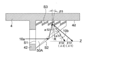
- FIGS. 5 to 8 show cross sections of the prisms 50A, 50B, 50C, and 50D and their peripheral portions, respectively.
- the prisms 50A, 50B, 50C, and 50D can be formed by, for example, an injection molding method or a press molding method using a thermoplastic resin as a material.
- thermoplastic resin include ZEONEX (registered trademark) 480R (refractive index 1.525, manufactured by Nippon Zeon Co., Ltd.), PMMA (polymethyl methacrylate, for example, Sumipex (registered trademark) MGSS, refractive index 1.49, Sumitomo Chemical Co., Ltd.), PC (polycarbonate, for example, Panlite (registered trademark) AD5503, refractive index 1.585, manufactured by Teijin Chemicals Ltd.), and the like. It can also be formed by press molding using glass as a material.
- the surface S3 of the prism 50K is a blazed reflection diffraction grating.
- a metal reflective film such as Al and Ag, and a dielectric multilayer film are provided.
- the light 10a incident on the prism 50K is reflected by the surface S2, and is incident on the surface S3 having a reflective diffraction grating substantially perpendicularly.
- the light incident on the surface S3 is diffracted and emitted from the surface S2.
- the diffraction angle ⁇ is ⁇ 21> ⁇ 22 (3) It becomes.
- the incident angle of the light propagation element 20 to the diffraction grating 20a is ⁇ 21 ⁇ 22 (4) It becomes.
- the prism 50 is actually formed of glass, resin, or the like whose coefficient of thermal expansion is not zero, and its shape changes according to the ambient temperature due to the coefficient of thermal expansion of the material.
- FIG. 12 shows a cross section of a peripheral portion of a prism 50L fixed to the suspension 4 shown in FIG.
- the prism 50L in FIG. 12 has the same shape as the prism 50A.
- a resin prism 50L is fixed to the lower surface 4d of a metal suspension 4 such as stainless steel via an adhesive 55.
- the shape before the increase of the ambient temperature is indicated by a broken line, and the shape after the increase is indicated by a solid line. Since the surface S3 on which the diffraction grating is provided is fixed to the metal suspension 4 having a smaller thermal expansion coefficient than that of the resin, there is no shape displacement that causes a problem due to temperature rise. In practice, the shape displacement due to the temperature rise also occurs in places other than those indicated by the solid line, but for ease of explanation, the characteristic shape displacement is shown in a simplified manner. In the following description, the shape before the increase in the ambient temperature is indicated by a broken line, the shape after the increase is indicated by a solid line, and simplified as described above.
- the fact that the incident angles ⁇ 31 and ⁇ 32 are larger than before the temperature rise is not for the specific wavelength of the light 10a, but is applied to all wavelengths of the light 10a incident on the prism 50L.
- the light 10a from the light source is color-corrected by the prism 50L, the incident angle to the light propagation element 20 is deviated from the optimum angle, and the optical coupling efficiency is lowered and stabilized. Optical recording may not be possible.
- This embodiment is obtained as a result of earnestly examining a method of fixing the prism provided with the diffraction grating to the suspension 4 so that the incident angle to the light propagation element 20 does not deviate from the optimum angle.
- the light 10a is incident on the surface S1, the incident light is reflected by the surface S2 which is a reflection surface, and the reflected light is provided with a diffraction grating (reflection diffraction grating).
- the light is diffracted by the surface S3 which is a surface and is emitted from the surface S2.
- the light 10b emitted from the surface S2 enters the diffraction grating 20a that couples light to the light propagation element 20 at a predetermined incident angle, is converted into guided light, and propagates downward (in the direction of arrow 25) in FIG.
- the diffraction angle ⁇ is expressed by the equation (1) showing the relationship between the wavelengths ⁇ 1 and ⁇ 2. ⁇ 51> ⁇ 52 (5) It becomes. For this reason, the incident angle to the diffraction grating 20a is ⁇ 51 ⁇ 52 (6) It becomes.
- the period of the diffraction grating provided on the surface S3 of the prism 50A it is possible to cancel the wavelength dependence of the incident angle of the diffraction grating 20a represented by the equation (2).
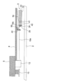
- the surface S1 is attached to the fixing plate 42 which is a fixing member provided in the suspension 4 with an adhesive or the like. Secure with. Specifically, a part of the suspension 4 is cut and bent to form the fixing plate 42, and the surface S1 of the prism 50A is fixed thereto.
- the fixing plate 42 may be a separate member fixed to the suspension 4.
- the fixed plate 42 is a metal plate having a surface perpendicular to the optical axis of the light 10a.
- the surface S3 and the lower surface 4d of the suspension 4 are in contact with each other to the extent that they are touched, and the surface S3 is not fixed to the suspension 4. Therefore, the prism 50A is fixed to the suspension 4 so that only the surface S1 restrains the displacement due to the temperature change, and the surface S3 which is the diffraction grating surface and the surface S2 which is the reflection surface are not fixed, and the temperature change. It is in a state where the displacement by can be made freely.
- the fixed plate 42 to which the surface S1 is fixed is provided with an opening through which the light beam 10a can pass without vignetting in the prism 50A.
- FIG. 9 shows a state in which the prism 50A fixed to the fixed plate 42 is viewed from the fixed plate 42 side.
- the fixing plate 42 has a frame shape including an opening 43 through which the light 10a passes, and the surface S1 is formed so that there is no exposed portion of the surface S1 except for the opening 43 so as to suppress displacement of the surface S1 due to temperature change as much as possible. It is preferable to fix to the fixing plate 42 as much as possible. By suppressing the displacement of the surface S1 as much as possible, the displacement effect of the reflecting surface and the diffraction grating surface in a freely displaceable state can be sufficiently obtained.
- the thermal expansion coefficient of the material forming the fixing plate 42 is preferably smaller than the thermal expansion coefficient of the material forming the prism 50A in order to suppress the shape displacement of the surface S1 as much as possible, and the fixing plate 42 has higher rigidity than the resin.
- the material of the fixing plate 42 is preferably a metal such as stainless steel, and the plate thickness is increased, for example, both edges of the fixing surface to which the surface S1 is fixed are bent substantially at right angles to the fixing surface.
- the rigidity may be increased by considering the above.
- the fixing plate 42 By increasing the rigidity of the fixing plate 42, it is possible to suppress deformation of the fixing plate 42 due to thermal expansion of the prism 50A, inclination of the surface S1, which is the fixing surface of the prism 50, with respect to the optical axis, and the like. In order to suppress the inclination of the fixing plate 42 itself, it is preferable to fix the fixing plate 42 to the suspension 4 with high rigidity.
- the surface S1 that is the incident surface is fixed to the fixed plate 42, and the surface S3 that includes the diffraction grating and the surface S2 that is the reflective surface are not fixed.
- the prism 50A is shown by a solid line after the temperature rise from the dotted line showing the temperature rise before FIG.
- the shape is displaced so as to extend in the optical axis direction of the light 10a, and does not extend in the direction perpendicular to the optical axis of the light 10a as shown in FIG. For this reason, unlike the case of FIG.
- the surface S2 which is a reflection surface, has a smaller inclination, an increased incident angle of the light 10a, and is substantially perpendicular to the surface S3 including the diffraction grating before the temperature rises.
- the incident angle changes to an angle ⁇ 5 in the opposite direction to the case of FIG.
- the 0th-order light direction R due to the diffraction grating is inclined by ⁇ 5 compared to before the temperature rise. This change reduces the incident angles ⁇ 51 and ⁇ 52 to the light propagation element 20.
- the surface S3 provided with the diffraction grating expands and extends in the grating pitch direction along the lower surface 4d of the suspension 4, whereby the period of the diffraction grating increases and the diffraction angle ⁇ decreases. That is, ⁇ 51 ⁇ 21 and ⁇ 52 ⁇ 22, and the incident angles ⁇ 51 and ⁇ 52 to the light propagation element 20 are increased.
- the change in the inclination of the surface S2 and the change in the period of the diffraction grating on the surface S3 can have a relationship in which the influence on the change in the incident angle to the light propagation element 20 is canceled out.
- the material forming the prism 50 when selecting the material forming the prism 50, special considerations such as selecting a material having a thermal expansion coefficient as small as possible are not required, so that the selection range of the material is widened, which is useful for design and manufacturing.
- the prism 50B is another specific example of a prism provided with a reflective diffraction grating.
- the light 10a enters the surface S1, the incident light is reflected by the surface S2, and the reflected light is diffracted by the surface S3 provided with a diffraction grating (reflective diffraction grating) and exits from the surface S2. Is done.
- the light 10b emitted from the surface S2 enters the diffraction grating 20a of the light propagation element 20 at a predetermined incident angle, is converted into guided light, and propagates downward (in the direction of arrow 25) in FIG.
- the prism 50B is fixed to the fixed plate 42 in the same manner as the prism 50A on the surface S1, which is the incident surface.
- a gap is provided between the surface S3, which is a diffraction grating surface, and the suspension 4 so as not to touch the suspension 4 even when the surface S3 is extended and displaced by thermal expansion.
- the surface S1 which is the incident surface is fixed to the fixed plate 42, and the surface S3, which is the diffraction grating surface, and the surface S2, which is the reflection surface, are not fixed and can be freely displaced due to temperature changes.
- the prism 50B is shown by a solid line after the temperature rise from the dotted line showing the temperature rise before FIG.
- the shape of the light 10a is displaced in the direction of the optical axis so as to extend toward the suspension 4 side.
- the surface S2 which is a reflection surface, has a large inclination
- the incident angle of the light 10a becomes small, and is substantially perpendicular to the surface S3 which is a diffraction grating surface before the temperature rises.
- the incident angle changes in the opposite direction to that in FIG. This change increases the incident angles ⁇ 51 and ⁇ 52 to the light propagation element 20.
- the surface S3 including the diffraction grating extends in the grating pitch direction due to thermal expansion and falls to the suspension 4 side. Therefore, the surface S3 which is a diffraction grating surface on which the light 10a reflected by the surface S2 is incident is illustrated in FIG. As shown in FIG. This change reduces the incident angles ⁇ 51 and ⁇ 52 to the light propagation element 20. Incidentally, the incident angle of the reflected light from the surface S2 with respect to the surface S3 which is the inclined diffraction grating surface is denoted by ⁇ 6.
- the change due to the inclination of the surface S3 is set to be superior to the change due to the inclination of the surface S2 at the incident angles ⁇ 51 and ⁇ 52. That is, the amount of change in the inclination of the surface S3 is made larger than the amount of change in the inclination of the surface S2. Therefore, the change in the inclination of the surfaces S2 and S3 results in a decrease in the incident angles ⁇ 61 and ⁇ 62 to the light propagation element 20.
- the diffraction grating on the surface S3 expands and extends in the grating pitch direction, whereby the period of the diffraction grating increases and the diffraction angle ⁇ decreases. That is, ⁇ 61 ⁇ 21 and ⁇ 62 ⁇ 22, and the incident angles ⁇ 61 and ⁇ 62 to the light propagation element 20 are increased.
- the change in the inclination of the surfaces S2 and S3 and the change in the period of the diffraction grating can be in a relationship in which the influences on the change in the incident angle to the light propagation element 20 are canceled each other.
- the deflection in the prism 50B is set by setting the inclination change of the surface S2 and the surface S3 and the period change of the diffraction grating of the surface S3 just to cancel each other at the incident angle to the light propagation element 20 due to the temperature change.
- the angle can be prevented from fluctuating regardless of temperature change.
- the optical coupling to the light propagation element 20 is stable,
- the optical recording head 3 can perform optical recording stably.
- the prism 7 is another specific example of a prism provided with a transmissive diffraction grating.
- the light 10a enters the surface S1, the incident light is reflected by the surface S2, and the reflected light is diffracted and emitted by the surface S3 provided with a diffraction grating (transmission diffraction grating).
- the light 10b emitted from the surface S3 enters the diffraction grating 20a of the light propagation element 20 at a predetermined incident angle, is converted into guided light, and propagates downward (in the direction of arrow 25) in FIG.
- the prism 50C is fixed to the fixed plate 42 in the same manner as the prism 50A on the surface S1, which is the incident surface.
- a surface S4 facing the surface S3 provided with the diffraction grating is fixed to the lower surface 4d of the suspension 4.
- the incident surface S1 is fixed to the fixing plate 42, the surface S4 is fixed to the suspension 4, and the diffraction grating surface S3 and the reflecting surface S2 are not fixed.
- This is a state in which displacement due to temperature change can be made freely.
- the prism 50C moves from the dotted line indicating the temperature before the temperature rise in FIG. As indicated by the solid line, the shape is displaced so as to extend in the optical axis direction of the light 10a.
- the surface S2 which is a reflection surface, has a large inclination, and the incident angle to the surface S3, which is a diffraction grating surface, is reduced by an angle ⁇ 7. This change reduces the incident angles ⁇ 71 and ⁇ 72 to the light propagation element 20.
- the diffraction grating on the surface S3 expands and extends in the grating pitch direction, whereby the period of the diffraction grating increases and the diffraction angle ⁇ decreases. That is, ⁇ 71 ⁇ 21 and ⁇ 72 ⁇ 22, and the incident angles ⁇ 71 and ⁇ 72 to the light propagation element 20 are increased.
- the change in the inclination of the surface S2 and the change in the period of the diffraction grating on the surface S3 can have a relationship in which the influence on the change in the incident angle to the light propagation element 20 is canceled out.
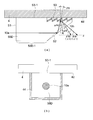
- a prism 50D shown in FIG. 8A is added to the prism 50A shown in FIG. 5 with a columnar portion 50D-1 in which the same cross-sectional shape (square shape) as the surface S1 of the prism 50A extends in the incident direction of the light 10a.
- the light 10a enters the surface S1, the incident light 10a passes through the columnar part 50D-1, is reflected by the surface S2 on the back of the optical path, and the reflected light is a diffraction grating (reflection) provided on the surface S3. Is diffracted by the mold diffraction grating) and emitted from the surface S2.
- the light 10b emitted from the surface S2 enters the diffraction grating 20a of the light propagation element 20 at a predetermined incident angle, is converted into guided light, and propagates downward (in the direction of arrow 25) in FIG.
- the prism 50D is provided with a diffraction grating having a surface S3 perpendicular to a deflection surface (a surface parallel to the paper surface in FIG. 8A) on which the light 10a is deflected on the side surface of the columnar portion 50D-1.
- the surface S3-1 which is not formed is fixed to the lower surface 4d of the suspension 4 which is a fixing member in this case.
- the diffraction grating surface of the surface S3 and the surface S2, which is a reflection surface, are not fixed and are in a state where they can be freely displaced due to temperature changes.
- FIG. 8B shows a state in which the prism 50D is viewed from the side on which the light 10a is incident.
- a metal frame 44 made of, for example, stainless steel or the like having the same thermal expansion coefficient as that of the suspension 4 is smaller than the material forming the prism 50D.
- -1 is in contact with -1.
- the thermal expansion of the columnar part 50D-1 can be suppressed.
- the space between the columnar part 50D-1 and the frame 44 may be fixed with an adhesive or the like.
- the diffraction grating on the surface S3 expands and extends in the grating pitch direction along the lower surface 4d of the suspension 4, whereby the period of the diffraction grating increases and the diffraction angle ⁇ decreases. That is, ⁇ 81 ⁇ 21 and ⁇ 82 ⁇ 22, and the incident angles ⁇ 81 and ⁇ 82 to the light propagation element 20 are increased.
- the change in the inclination of the surface S2 and the change in the period of the diffraction grating on the surface S3 can have a relationship in which the influence on the change in the incident angle to the light propagation element 20 is canceled out.
- the embodiment described above relates to an optically assisted magnetic recording head and an optically assisted magnetic recording apparatus.
- the main configuration of the embodiment is an optical recording head, optical It can also be used for a recording apparatus.
- the magnetic recording unit 40 and the magnetic reproducing unit 41 provided on the slider 30 are unnecessary.
Landscapes
- Physics & Mathematics (AREA)
- Electromagnetism (AREA)
- Engineering & Computer Science (AREA)
- Manufacturing & Machinery (AREA)
- Optical Head (AREA)
- Magnetic Heads (AREA)
- Adjustment Of The Magnetic Head Position Track Following On Tapes (AREA)
- Recording Or Reproducing By Magnetic Means (AREA)
Abstract
Description
前記光学素子は、前記入射光を偏向するための反射面と回折格子面とを有し、
前記光学素子は、前記反射面及び前記回折格子面の温度変化による変位が自在な状態で、前記光学素子の前記反射面及び前記回折格子面以外の部分において温度変化による変位を拘束するように前記固定部材に固定され、
前記反射面及び前記回折格子面の前記変位による傾斜変化により生じる前記入射光の偏向角の変化は、前記回折格子面の前記変位による回折格子の周期変化により生じる回折角度の変化により抑えられることを特徴とする光学装置。
前記光学素子は、前記柱状部の側面において前記固定部材に固定されていることを特徴とする前記1から3の何れか一項に記載の光学装置。
前記記録媒体に光を照射するための光伝搬素子を備えたスライダと、
前記スライダを前記記録媒体に対して相対移動可能に支持するサスペンションと、
前記4に記載の光学装置と、を有し、
前記固定部材は、前記サスペンションに固定され、
前記光学素子は、偏向した光を前記光伝搬素子に入射させることを特徴とする光記録ヘッド。
前記記録媒体に光を照射するための光伝搬素子を備えたスライダと、
前記スライダを前記記録媒体に対して相対移動可能に支持するサスペンションと、
前記5又は6に記載の光学装置と、を有し、
前記固定部材は、前記サスペンションであり、
前記光学素子は、偏向した光を前記光伝搬素子に入射させることを特徴とする光記録ヘッド。
前記光学素子は、前記グレーティングカプラに対して光を入射させることを特徴とする前記7又は8に記載の光記録ヘッド。
前記光源からの光を前記光学素子への入射光とする前記7から9の何れか一項に記載の光記録ヘッドと、
前記記録媒体と、を備えていることを特徴とする光記録装置。
(1)記録用のディスク(記録媒体)2
(2)支軸6を支点として矢印Aの方向(トラッキング方向)に回転可能に設けられたアーム5に支持されたサスペンション4
(3)アーム5に取り付けられたトラッキング用アクチュエータ7
(4)サスペンション4の先端に結合部材4aを介して取り付けられた光アシスト式磁気記録ヘッド(以下、光記録ヘッド3と称する。)
(5)ディスク2を矢印Bの方向に回転させるモータ(図示しない)
(6)トラッキング用アクチュエータ6、モータ及びディスク2に記録するために書き込み情報に応じて照射する光、磁界の発生等の光記録ヘッド3の制御を行う制御部8
光記録装置100においては、光記録ヘッド3がディスク2上で浮上しながら相対的に移動しうるように構成されている。
λ1>λ2・・・・・(1)
とした場合、
θ11<θ12・・・(2)
となる。これは、波長が大きくなると回折角度が大きくなるため、回折格子20aへの最適入射角度は小さくなるからである。
α21>α22・・・(3)
となる。このため、光伝搬素子20の回折格子20aへの入射角度は、
θ21<θ22・・・(4)
となる。
α51>α52・・・(5)
となる。このため、回折格子20aへの入射角度は、
θ51<θ52・・・(6)
となる。プリズム50Aの面S3に設ける回折格子の周期を調整することで、式(2)で示した回折格子20aの入射角度の波長依存性を打ち消すことができる。
2 ディスク
3 光記録ヘッド
4 サスペンション
5 アーム
10 光源
10a、10b 光
12 レンズ
20 光伝搬素子
21 コア層
22 下クラッド層
23 上クラッド層
24 下端面
24d プラズモンアンテナ
26、27 側面
20a 回折格子
30 スライダ
32 空気ベアリング面
40 磁気記録部
41 磁気再生部
42 固定板
50、50A、50B、50C、50D、50K、50L プリズム
100 光記録装置
C 軸
F 焦点
R 0次光方向
Claims (10)
- 入射光を偏向する光学素子と、該光学素子が固定される固定部材とを有する光学装置において、
前記光学素子は、前記入射光を偏向するための反射面と回折格子面とを有し、
前記光学素子は、前記反射面及び前記回折格子面の温度変化による変位が自在な状態で、前記光学素子の前記反射面及び前記回折格子面以外の部分において温度変化による変位を拘束するように前記固定部材に固定され、
前記反射面及び前記回折格子面の前記変位による傾斜変化により生じる前記入射光の偏向角の変化は、前記回折格子面の前記変位による回折格子の周期変化により生じる回折角度の変化により抑えられることを特徴とする光学装置。 - 前記固定部材をなす材料の熱膨張係数は、前記光学素子をなす材料の熱膨張係数未満であることを特徴とする請求項1に記載の光学装置。
- 前記固定部材の材料は金属であり、前記光学素子の材料は樹脂であることを特徴とする請求項2に記載の光学装置。
- 前記光学素子における前記入射光が入射される面が前記固定部材に固定されていることを特徴とする請求項1から3の何れか一項に記載の光学装置。
- 前記光学素子は、前記入射光が入射される面を有する柱状部を備え、
前記反射面及び前記回折格子面は、前記柱状部を透過した光を受ける位置に設けられており、
前記光学素子は、前記柱状部の側面において前記固定部材に固定されていることを特徴とする請求項1から3の何れか一項に記載の光学装置。 - 前記柱状部の周囲は、前記光学素子をなす材料の熱膨張係数未満の熱膨張係数の材料の枠体が前記柱状部の側面に接する状態で被われていることを特徴とする請求項5に記載の光学装置。
- 光を用いて記録媒体に情報記録を行う光記録ヘッドにおいて、
前記記録媒体に光を照射するための光伝搬素子を備えたスライダと、
前記スライダを前記記録媒体に対して相対移動可能に支持するサスペンションと、
請求項4に記載の光学装置と、を有し、
前記固定部材は、前記サスペンションに固定され、
前記光学素子は、偏向した光を前記光伝搬素子に入射させることを特徴とする光記録ヘッド。 - 光を用いて記録媒体に情報記録を行う光記録ヘッドにおいて、
前記記録媒体に光を照射するための光伝搬素子を備えたスライダと、
前記スライダを前記記録媒体に対して相対移動可能に支持するサスペンションと、
請求項5又は6に記載の光学装置と、を有し、
前記固定部材は、前記サスペンションであり、
前記光学素子は、偏向した光を前記光伝搬素子に入射させることを特徴とする光記録ヘッド。 - 前記光伝搬素子は、光を伝搬する導波路と、該導波路に光を結合するためのグレーティングカプラとを有し、
前記光学素子は、前記グレーティングカプラに対して光を入射させることを特徴とする請求項7又は8に記載の光記録ヘッド。 - 光源と、
前記光源からの光を前記光学素子への入射光とする請求項7から9の何れか一項に記載の光記録ヘッドと、
前記記録媒体と、を備えていることを特徴とする光記録装置。
Priority Applications (2)
| Application Number | Priority Date | Filing Date | Title |
|---|---|---|---|
| US13/057,666 US20110134740A1 (en) | 2008-08-08 | 2009-07-13 | Optical Device, Optical Recording Head and Optical Recording Device |
| JP2009540529A JP4479860B2 (ja) | 2008-08-08 | 2009-07-13 | 光記録ヘッド及び光記録装置 |
Applications Claiming Priority (2)
| Application Number | Priority Date | Filing Date | Title |
|---|---|---|---|
| JP2008205286 | 2008-08-08 | ||
| JP2008-205286 | 2008-08-08 |
Publications (1)
| Publication Number | Publication Date |
|---|---|
| WO2010016360A1 true WO2010016360A1 (ja) | 2010-02-11 |
Family
ID=41663583
Family Applications (1)
| Application Number | Title | Priority Date | Filing Date |
|---|---|---|---|
| PCT/JP2009/062669 Ceased WO2010016360A1 (ja) | 2008-08-08 | 2009-07-13 | 光学装置、光記録ヘッド及び光記録装置 |
Country Status (3)
| Country | Link |
|---|---|
| US (1) | US20110134740A1 (ja) |
| JP (1) | JP4479860B2 (ja) |
| WO (1) | WO2010016360A1 (ja) |
Families Citing this family (2)
| Publication number | Priority date | Publication date | Assignee | Title |
|---|---|---|---|---|
| US8274866B2 (en) * | 2009-03-11 | 2012-09-25 | Konica Minolta Opto, Inc. | Optical recording head and optical recording apparatus |
| CN111145788A (zh) * | 2018-11-02 | 2020-05-12 | 新科实业有限公司 | 热辅助磁记录头及热辅助磁记录磁盘驱动器 |
Citations (5)
| Publication number | Priority date | Publication date | Assignee | Title |
|---|---|---|---|---|
| JPH0210527A (ja) * | 1988-06-29 | 1990-01-16 | Hitachi Ltd | 光集積回路 |
| JPH02162304A (ja) * | 1988-12-16 | 1990-06-21 | Fuji Photo Film Co Ltd | 導波光と外部光との結合方法 |
| JP2002116314A (ja) * | 2000-10-06 | 2002-04-19 | Sankyo Seiki Mfg Co Ltd | 回折素子および光ピックアップ装置 |
| JP2004264446A (ja) * | 2003-02-28 | 2004-09-24 | Hitachi Cable Ltd | 回折格子、デマルチプレクサ及び波長多重光伝送モジュール |
| JP2007220174A (ja) * | 2006-02-15 | 2007-08-30 | Fujitsu Ltd | 磁気ヘッド、および情報記憶装置 |
Family Cites Families (4)
| Publication number | Priority date | Publication date | Assignee | Title |
|---|---|---|---|---|
| US5070488A (en) * | 1988-06-29 | 1991-12-03 | Atsuko Fukushima | Optical integrated circuit and optical apparatus |
| US5081615A (en) * | 1988-12-16 | 1992-01-14 | Fuji Photo Film Co., Ltd. | Method of coupling external light into an optical waveguide and a guided wave from an optical waveguide and optical pickup employing an optical waveguide |
| US6944112B2 (en) * | 2002-06-28 | 2005-09-13 | Seagate Technology Llc | Heat assisted magnetic recording head with a planar waveguide |
| US20110075526A1 (en) * | 2008-05-14 | 2011-03-31 | Koujirou Sekine | Optical Element, Arm Mechanism, and Information Recording Device |
-
2009
- 2009-07-13 WO PCT/JP2009/062669 patent/WO2010016360A1/ja not_active Ceased
- 2009-07-13 JP JP2009540529A patent/JP4479860B2/ja not_active Expired - Fee Related
- 2009-07-13 US US13/057,666 patent/US20110134740A1/en not_active Abandoned
Patent Citations (5)
| Publication number | Priority date | Publication date | Assignee | Title |
|---|---|---|---|---|
| JPH0210527A (ja) * | 1988-06-29 | 1990-01-16 | Hitachi Ltd | 光集積回路 |
| JPH02162304A (ja) * | 1988-12-16 | 1990-06-21 | Fuji Photo Film Co Ltd | 導波光と外部光との結合方法 |
| JP2002116314A (ja) * | 2000-10-06 | 2002-04-19 | Sankyo Seiki Mfg Co Ltd | 回折素子および光ピックアップ装置 |
| JP2004264446A (ja) * | 2003-02-28 | 2004-09-24 | Hitachi Cable Ltd | 回折格子、デマルチプレクサ及び波長多重光伝送モジュール |
| JP2007220174A (ja) * | 2006-02-15 | 2007-08-30 | Fujitsu Ltd | 磁気ヘッド、および情報記憶装置 |
Also Published As
| Publication number | Publication date |
|---|---|
| US20110134740A1 (en) | 2011-06-09 |
| JPWO2010016360A1 (ja) | 2012-01-19 |
| JP4479860B2 (ja) | 2010-06-09 |
Similar Documents
| Publication | Publication Date | Title |
|---|---|---|
| JP5777585B2 (ja) | 導波路を備えた装置、方法、およびシステム | |
| US8228779B2 (en) | System to deliver light to a slider for heat-assisted recording | |
| US8730780B2 (en) | Light delivery waveguide | |
| JPWO2008001594A1 (ja) | 光ヘッド、光磁気ヘッド及び光記録装置 | |
| US20090208171A1 (en) | Waveguide For Heat Assisted Magnetic Recording | |
| US8599655B2 (en) | Near field light generator, optical recording head and optical recording apparatus | |
| US20100046889A1 (en) | Apparatus and Method For Coupling Light to a Thin Film Optical Waveguide | |
| WO2010010806A1 (ja) | 光記録ヘッド及び光記録装置 | |
| KR20090037803A (ko) | 헤드 슬라이더 | |
| JPWO2009139258A1 (ja) | 光学素子、および光アシスト式の磁気記録ヘッド | |
| JP4479860B2 (ja) | 光記録ヘッド及び光記録装置 | |
| WO2010104030A1 (ja) | 光記録ヘッド及び光記録装置 | |
| WO2010007897A1 (ja) | 偏向光学素子、光記録ヘッド及び光記録装置 | |
| JP4297199B2 (ja) | 光ヘッド、光アシスト式磁気記録ヘッド及び光記録装置 | |
| JPWO2008142917A1 (ja) | 光記録ヘッド、光アシスト式磁気記録ヘッド及び光記録装置 | |
| WO2010082404A1 (ja) | 光学装置、光記録ヘッド及び光記録装置 | |
| JP2009110562A (ja) | 光学素子及び光ヘッド | |
| JP4788661B2 (ja) | 光ヘッドの製造方法 | |
| JP2009283051A (ja) | 光学素子、光記録ヘッド及び光記録装置 | |
| JP2010027184A (ja) | 光学装置、光記録ヘッド及び光記録装置 | |
| JP2008305501A (ja) | 光学素子、光ヘッド | |
| WO2010100994A1 (ja) | 光学素子及び光記録ヘッド | |
| JP2010123200A (ja) | 光学装置、光記録ヘッド及び光記録装置 | |
| WO2011078025A1 (ja) | 光アシスト磁気ヘッド | |
| JP2009301602A (ja) | 光学素子、光記録ヘッド及び光記録装置 |
Legal Events
| Date | Code | Title | Description |
|---|---|---|---|
| ENP | Entry into the national phase |
Ref document number: 2009540529 Country of ref document: JP Kind code of ref document: A |
|
| 121 | Ep: the epo has been informed by wipo that ep was designated in this application |
Ref document number: 09804847 Country of ref document: EP Kind code of ref document: A1 |
|
| WWE | Wipo information: entry into national phase |
Ref document number: 13057666 Country of ref document: US |
|
| NENP | Non-entry into the national phase |
Ref country code: DE |
|
| 122 | Ep: pct application non-entry in european phase |
Ref document number: 09804847 Country of ref document: EP Kind code of ref document: A1 |