WO2010007684A1 - Éolienne de génération d'énergie et son procédé de fabrication - Google Patents
Éolienne de génération d'énergie et son procédé de fabrication Download PDFInfo
- Publication number
- WO2010007684A1 WO2010007684A1 PCT/JP2008/062960 JP2008062960W WO2010007684A1 WO 2010007684 A1 WO2010007684 A1 WO 2010007684A1 JP 2008062960 W JP2008062960 W JP 2008062960W WO 2010007684 A1 WO2010007684 A1 WO 2010007684A1
- Authority
- WO
- WIPO (PCT)
- Prior art keywords
- wind
- power generation
- wind turbine
- blade
- wind power
- Prior art date
Links
- 238000004519 manufacturing process Methods 0.000 title claims description 18
- 238000010248 power generation Methods 0.000 claims abstract description 27
- 229910000838 Al alloy Inorganic materials 0.000 claims description 16
- 238000001125 extrusion Methods 0.000 claims description 12
- 238000000034 method Methods 0.000 claims description 9
- 238000005452 bending Methods 0.000 description 6
- 239000000463 material Substances 0.000 description 6
- 239000013585 weight reducing agent Substances 0.000 description 4
- 235000012438 extruded product Nutrition 0.000 description 3
- 230000002093 peripheral effect Effects 0.000 description 3
- 229920002430 Fibre-reinforced plastic Polymers 0.000 description 2
- 239000011151 fibre-reinforced plastic Substances 0.000 description 2
- 238000003780 insertion Methods 0.000 description 2
- 230000037431 insertion Effects 0.000 description 2
- 230000008719 thickening Effects 0.000 description 2
- 229910001069 Ti alloy Inorganic materials 0.000 description 1
- 239000002131 composite material Substances 0.000 description 1
- 230000007423 decrease Effects 0.000 description 1
- 230000000694 effects Effects 0.000 description 1
- 229910052751 metal Inorganic materials 0.000 description 1
- 239000002184 metal Substances 0.000 description 1
- 239000000203 mixture Substances 0.000 description 1
- 238000012986 modification Methods 0.000 description 1
- 230000004048 modification Effects 0.000 description 1
- 239000011343 solid material Substances 0.000 description 1
Images


Classifications
-
- F—MECHANICAL ENGINEERING; LIGHTING; HEATING; WEAPONS; BLASTING
- F03—MACHINES OR ENGINES FOR LIQUIDS; WIND, SPRING, OR WEIGHT MOTORS; PRODUCING MECHANICAL POWER OR A REACTIVE PROPULSIVE THRUST, NOT OTHERWISE PROVIDED FOR
- F03D—WIND MOTORS
- F03D3/00—Wind motors with rotation axis substantially perpendicular to the air flow entering the rotor
- F03D3/06—Rotors
- F03D3/062—Rotors characterised by their construction elements
-
- F—MECHANICAL ENGINEERING; LIGHTING; HEATING; WEAPONS; BLASTING
- F03—MACHINES OR ENGINES FOR LIQUIDS; WIND, SPRING, OR WEIGHT MOTORS; PRODUCING MECHANICAL POWER OR A REACTIVE PROPULSIVE THRUST, NOT OTHERWISE PROVIDED FOR
- F03D—WIND MOTORS
- F03D7/00—Controlling wind motors
- F03D7/06—Controlling wind motors the wind motors having rotation axis substantially perpendicular to the air flow entering the rotor
-
- F—MECHANICAL ENGINEERING; LIGHTING; HEATING; WEAPONS; BLASTING
- F05—INDEXING SCHEMES RELATING TO ENGINES OR PUMPS IN VARIOUS SUBCLASSES OF CLASSES F01-F04
- F05B—INDEXING SCHEME RELATING TO WIND, SPRING, WEIGHT, INERTIA OR LIKE MOTORS, TO MACHINES OR ENGINES FOR LIQUIDS COVERED BY SUBCLASSES F03B, F03D AND F03G
- F05B2240/00—Components
- F05B2240/20—Rotors
- F05B2240/21—Rotors for wind turbines
- F05B2240/211—Rotors for wind turbines with vertical axis
- F05B2240/214—Rotors for wind turbines with vertical axis of the Musgrove or "H"-type
-
- F—MECHANICAL ENGINEERING; LIGHTING; HEATING; WEAPONS; BLASTING
- F05—INDEXING SCHEMES RELATING TO ENGINES OR PUMPS IN VARIOUS SUBCLASSES OF CLASSES F01-F04
- F05B—INDEXING SCHEME RELATING TO WIND, SPRING, WEIGHT, INERTIA OR LIKE MOTORS, TO MACHINES OR ENGINES FOR LIQUIDS COVERED BY SUBCLASSES F03B, F03D AND F03G
- F05B2240/00—Components
- F05B2240/20—Rotors
- F05B2240/30—Characteristics of rotor blades, i.e. of any element transforming dynamic fluid energy to or from rotational energy and being attached to a rotor
- F05B2240/31—Characteristics of rotor blades, i.e. of any element transforming dynamic fluid energy to or from rotational energy and being attached to a rotor of changeable form or shape
- F05B2240/313—Characteristics of rotor blades, i.e. of any element transforming dynamic fluid energy to or from rotational energy and being attached to a rotor of changeable form or shape with adjustable flow intercepting area
-
- Y—GENERAL TAGGING OF NEW TECHNOLOGICAL DEVELOPMENTS; GENERAL TAGGING OF CROSS-SECTIONAL TECHNOLOGIES SPANNING OVER SEVERAL SECTIONS OF THE IPC; TECHNICAL SUBJECTS COVERED BY FORMER USPC CROSS-REFERENCE ART COLLECTIONS [XRACs] AND DIGESTS
- Y02—TECHNOLOGIES OR APPLICATIONS FOR MITIGATION OR ADAPTATION AGAINST CLIMATE CHANGE
- Y02E—REDUCTION OF GREENHOUSE GAS [GHG] EMISSIONS, RELATED TO ENERGY GENERATION, TRANSMISSION OR DISTRIBUTION
- Y02E10/00—Energy generation through renewable energy sources
- Y02E10/70—Wind energy
- Y02E10/74—Wind turbines with rotation axis perpendicular to the wind direction
-
- Y—GENERAL TAGGING OF NEW TECHNOLOGICAL DEVELOPMENTS; GENERAL TAGGING OF CROSS-SECTIONAL TECHNOLOGIES SPANNING OVER SEVERAL SECTIONS OF THE IPC; TECHNICAL SUBJECTS COVERED BY FORMER USPC CROSS-REFERENCE ART COLLECTIONS [XRACs] AND DIGESTS
- Y02—TECHNOLOGIES OR APPLICATIONS FOR MITIGATION OR ADAPTATION AGAINST CLIMATE CHANGE
- Y02P—CLIMATE CHANGE MITIGATION TECHNOLOGIES IN THE PRODUCTION OR PROCESSING OF GOODS
- Y02P70/00—Climate change mitigation technologies in the production process for final industrial or consumer products
- Y02P70/50—Manufacturing or production processes characterised by the final manufactured product
-
- Y—GENERAL TAGGING OF NEW TECHNOLOGICAL DEVELOPMENTS; GENERAL TAGGING OF CROSS-SECTIONAL TECHNOLOGIES SPANNING OVER SEVERAL SECTIONS OF THE IPC; TECHNICAL SUBJECTS COVERED BY FORMER USPC CROSS-REFERENCE ART COLLECTIONS [XRACs] AND DIGESTS
- Y10—TECHNICAL SUBJECTS COVERED BY FORMER USPC
- Y10T—TECHNICAL SUBJECTS COVERED BY FORMER US CLASSIFICATION
- Y10T29/00—Metal working
- Y10T29/49—Method of mechanical manufacture
- Y10T29/49316—Impeller making
- Y10T29/49336—Blade making
Definitions
- the present invention relates to a wind turbine for wind power generation and a method of manufacturing the same.
- a Savonius type with a shape that emphasizes the wind receiving area is generally known, and a blade can be rotated by a slight wind of about 1 m / sec, but the rotational torque during rotation is higher than the wind speed Can not get Further, as wind power generation using lift, a gyro mill type having a wing shape similar to that of an aircraft is generally known, and a blade can not be rotated by a slight wind generated during rotation.
- Patent Document 1 Patent No. 3451085 gazette
- an object of the present invention is to provide a wind turbine for wind power generation which can be started by a slight wind, suppresses disturbance of wind accompanying rotation, and is excellent in power generation efficiency.
- the present invention is a wind power having a plurality of blades provided at predetermined angles around the rotation axis in a plane orthogonal to a vertical axis, and the blades are streamlined airfoils having a lift coefficient of 1.0 or more.
- an opening is provided in the surface on the side of the rotation axis with respect to a chord, in the range of 55% to 95% from the leading edge with respect to the chord length.
- the area of the opening is 30% to 5% with respect to the surface on the rotation shaft side.
- a plurality of openings are provided.
- the member of the opening is thinner than the front of the blade.
- the present invention is a method of manufacturing a blade according to claim 1, wherein at least a part of the blade is manufactured by extrusion of an aluminum alloy.
- the present invention is a manufacturing method in which the front portion of the blade is manufactured by extrusion of an aluminum alloy.
- a stepped portion corresponding to the thickness of the rear side member is provided at an end portion of the connection portion, and the front portion of the rear side member disposed in the stepped portion has a hollow portion. It is a method.
- the present invention is the manufacturing method which provided the connecting part which connects the back side member in the front part.
- the rear member is thinner than the thickness of the front portion.
- this invention is a manufacturing method which manufactured the said connection part by extrusion molding of aluminum alloy.
- the present invention is a manufacturing method including a connecting means for connecting the front portion and the connecting portion.
- connection means includes a fitting portion provided on one of the front portion and the connection portion, and a fitting receiving portion provided on the other.
- the chord length away from the front edge of the surface on the rotating shaft side of the blade is 55 Since the opening is provided at a position of% to 95%, the disturbance of the flow of the wind on the side of the rotary shaft serving as the resistance is small, and a high rotational torque can be obtained.
- a wind can be caught efficiently at the time of starting by having several opening part.
- composition concerning a manufacturing method, uniform thickness and shape are securable by extrusion of aluminum alloy.
- the strength is improved by having the hollow portion.
- a back side member can be connected with a connection part.
- weight reduction can be measured by thinning a back side member.
- strength and uniform shape of a connection part are securable.
- step difference between a front part and a back side member can be eliminated by arrange
- a front part and a connection part can be connected by a connection means.
- a front part and a connection part can be connected by fitting with a fitting part and a fitting receiving part.
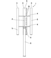
- FIG. 1 to 6 show a first embodiment of the present invention, and as shown in the figure, a vertical axis type wind turbine 1 is provided with a vertical rotation axis 2 at the center.
- a plurality of blades 3 are arranged at equal intervals in the circumferential direction around the rotation axis 2, and in this example, three blades 3, 3, 3 are arranged in parallel with the rotation axis 2, that is, the blades 3 In the plane orthogonal to the rotation axis 2, they are arranged at equal angular intervals (120 degrees in this embodiment) along the circumferential direction of the same radius.
- the blade 3 is fixed to an end of an arm 4 radially extending from the rotation shaft 2 at a predetermined angle with respect to the support rod 4. Further, a plurality of arms 4 are provided in the longitudinal direction of the blade 3 and in this example, two are provided.
- the outer skin of the blade 3 is formed of a thin plate-like material made of a light metal such as aluminum alloy or titanium alloy, or a composite material such as fiber reinforced plastic (FRP).
- the wing shape of the blade 3 is streamlined with a lift coefficient of 1.0 or more, preferably 1.0 to 1.4, and in particular, the main wing of an asymmetric wing light aircraft (airplane with a take-off weight of 5700 kg or less)
- the shape used in the above is preferable, for example, a 4-shaped wing type, an RAF wing type, a Gottingen wing type and the like.
- the surface (the surface on the outer peripheral side) where the expansion of the airfoil is large is the surface 5 of the blade 3 and the surface (the surface on the inner peripheral side) where the expansion of the airfoil is small is the back surface 6 of the blade 3
- the back surface is the surface on the rotating shaft side.
- a connecting member 7 is provided in the blade 3 to connect the front surface 5 side and the back surface 6 side, and the connecting member 7 is formed of the same thin plate material as the outer skin of the blade 3. , Deformation of the blade 3 at the time of rotation is prevented.
- reference numeral 8 denotes a generator connected to the rotary shaft 2 at the top, and the generator 8 is provided on the pole 9.
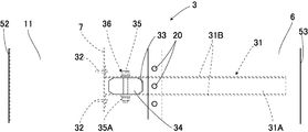
- the front portion 11 of the blade 3 is formed of an extruded product of aluminum alloy, and the front portion 11 extends from the connecting member 7 to the hollow portion 12 on the front side and from the connecting portion 7 to the rear side.
- the front surface connecting portion 13 and the back surface connecting portion 14 are integrally formed, and the same cross section continues in the length direction by extrusion molding.
- a front surface mounting portion 16 is formed on the rear end side of the front surface connection portion 13 by an inwardly recessed step portion 15, and on the rear end side of the back surface connection portion 14 by an inwardly recessed step portion 17.
- a back surface mounting portion 18 is formed, and a front cover member 19 formed of a plate thinner than the front portion 11 is fixed to the outer surface of the front surface mounting portion 16 by a rivet 20 serving as a fixing means.
- a back cover member 21 made of a plate thinner than the front portion 11 is fixed by rivets 20.
- the stepped portions 15 and 17 are configured such that no step is formed on the front surface 5 and the back surface 6. Further, at the rear ends of the front surface connection portion 13 and the rear surface connection portion 14, bending edge portions 13A and 14A which are bent at a substantially right angle inside are formed. And these front cover material 19 and back cover material 21 are back side members.
- reference numeral 22 denotes a plurality of screw holes provided in the front portion 11, which are provided in the hollow portion 12 and provided in two places at two end corners of the connecting member 7 and in two places on the front side. .
- the blade 3 is provided with an arm support member 31 corresponding to the mounting position of the arm 4 and this arm support member 31 has a substantially U-shaped cross section having side portions 31B and 31B on both sides of the central portion 31A.
- the central portion 31A is aligned with the inner surface of the surface connection portion 13 and the front cover member 19, and is fixed to the front cover member 19 by the plurality of rivets 20 of the central portion 31a.
- the front side of the side portions 31B and 31B is the surface connection portion It is fixed between 13 and the back surface connection portion 14.
- a receiving groove portion 131A into which the bending edge portion 13A is fitted is formed on the central portion 31A side, and the bending edge portion 14A is fitted into the arm support member 31.
- the receiving groove portion 131B is formed at the edge of the side portion 31B.
- the front side of the arm support member 31 is fixed to the connecting member 7 by a screw 32 as a fixing member.
- an insertion hole 33 is formed in the back surface connecting portion 13 corresponding to the mounting position of the arm 4, and the arm receiving member 34 is inserted into the insertion hole 33, and the arm receiving member 34 is made of the arm 4.
- the tip is inserted and the tip is inserted between the side portions 31B and 31B, and in the blade 3, a plurality of bolts 35 are inserted into the side portions 31B and 31B and the arm support 34, and the nut 35A is screwed
- the arm support 34 is fixed to the blade 3.
- the arm 4 is externally fitted to the arm receiving member 34 protruding from the blade 3 and the arm 4 is fixed to the arm receiving member 34 by the plurality of bolts 35 and the nuts 35A.
- the arm support 34 is made of an extruded product of aluminum alloy and is made of solid material.
- an arm fixing means 36 for fixing the arm 4 to the blade 3 is constituted by the arm support member 31, the arm support 34, the bolt 35 and the nut 35A.
- cover plates 41 for closing the end portions are provided.
- the cover plate 41 is fixed by a fixing member 42 having a substantially L-shaped cross section, one side piece 42A of the fixing member 42 is fixed to the inner surface of the blade 3 by a rivet 20, and the other side piece 42B of the fixing member 42 is fixed.
- the cover plate 41 is fixed by rivets 20. Further, the front side of the cover plate 41 is fixed by inserting a screw (not shown) into the cover plate 41 and screwing the screw into the screw hole 22.
- a receiving groove portion 131A into which the bending edge portion 13A is inserted is formed in one side piece, and a receiving groove portion into which the bending edge portion 14A is inserted into the arm support member 31. 131B are formed on the edge of the side 31B.
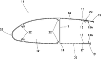
- the blade 3 is provided with a plurality of openings 51, 51...
- the openings 51 are preferably in the range of 55% to 95%, preferably 75% to 95% from the leading edge 52, between the leading edge 52 and the trailing edge 53.
- the total area of the openings 51, 51... Is 30% to 5%, preferably 20% to 5%, of the area of the back surface 6.
- the blade 3 is formed into an airfoil that has a low Reynolds number and a high lift coefficient, and has a structure with less disturbance of the air flow on the back surface 6 side in the high wind speed region.
- chords 54 of the blade 3 are attached at an angle of 0 degrees to 5 degrees with respect to the wind direction (normal direction to the rotational direction T) to the blade 3.
- W is the direction in which the wind blows.
- a plurality of blades 3 are provided at predetermined angles around the rotation axis 3 in a plane orthogonal to the rotation axis 3, and the blades 3 are streamlined having a lift coefficient of 1.0 or more.
- the back surface 6 on the side of the rotary shaft with respect to the chord 54 has an opening within the range of 55% to 95% from the leading edge 52 with respect to the chord length. Since the 51 is provided, it can be activated even by a slight wind due to the drag at the opening 51, and in the high wind speed region rotated by the lift of the blade 3, 55 with respect to the chord length distant from the front edge 52 of the back surface 6 of the blade 3. Since the openings 51 are provided at the positions of% to 95%, the disturbance of the flow of the wind on the back surface 6 which is a resistance can be reduced, and a high rotational torque can be obtained.
- the area of the opening 51 is 30% to 5% with respect to the back surface 6 that is the surface on the rotating shaft side, so that the disturbance of the wind flow is further reduced.
- the plurality of openings 51 are provided, so that the wind can be efficiently caught at the time of startup.
- the back cover member 21 which is a member of the opening 51 is thinner than the front portion 11 of the blade 3, the strength of the front portion 11 is increased by thickening the front portion 11 where the wind resistance is large. By making the member of the opening 51 thinner, it is possible to achieve weight reduction.
- the front portion 11 of the blade 6 is manufactured by extrusion of an aluminum alloy, it is possible to ensure the strength and the uniform shape of the front portion 11 having a large wind resistance.
- the strength is improved by the hollow portion 12.
- the front and back joint portions 13 and 15 for connecting the front cover member 19 and the back cover member 21 as the rear member are provided in the front portion 11, the front and rear joint portions 13, The front cover 19 and the back cover 21 can be connected to each other.
- the weight reduction is achieved by thinning the front cover member 19 and the back cover member 21.
- the connecting portions 13 and 15 are manufactured by extrusion of an aluminum alloy, the strength and the uniform shape of the connecting portions 13 and 15 can be secured.
- the step portions 15 and 17 corresponding to the thickness of the front cover member 19 and the back cover member 21 serving as the rear members are provided at the end portions of the connection portions 13 and 15. , 17, since the front sides of the front cover 19 and the back cover 21 are arranged, it is possible to eliminate the occurrence of a step between the front 11 and the front cover 19 and the back cover 21.
- the cover plate 41 or the like can be easily attached to the end portion by a screw.
- FIG. 7 shows a second embodiment of the present invention, in which the same parts as those of the first embodiment are designated by the same reference numerals, and the detailed description is omitted.
- the front portion 11 includes a hollow portion 12 and a divided portion 61 provided separately from the hollow portion 12, and the divided portion 61 is a front end of the front surface connection portion 13 and the rear surface connection portion 14.
- the divided portion 61 is a front end of the front surface connection portion 13 and the rear surface connection portion 14.
- a plate-like rear connecting member 62 are connected by a plate-like rear connecting member 62, and a groove-like fitting groove 7A is provided in the connecting member 7, and the rear connecting member 62 is fitted in the fitting groove 7A.
- a fitting portion 62A is formed.
- the connection means 63 is comprised by 7 A of fitting grooves which are the fitting receiving parts, and the fitting part 62A.
- the front portion 11 and the divided portion 61 are respectively formed of an extruded product of an aluminum alloy. Further, in the hollow portion 12, the screw holes 22 are provided at two positions at both end corner portions of the connecting member 7, at two positions on the center side, and at two positions on the front side.
- the connecting part 63 since the connecting means 63 for connecting the front part 11 and the connecting parts 13 and 15 is integrally formed, the connecting part 63 includes the dividing part 61 having the front part 11 and the connecting parts 13 and 15. It can be linked.
- connection means 63 is a fitting portion 62A provided on one of the front portion 11 and the divided portion 61 having the connection portions 13 and 15, and a fitting receiving portion provided on the other. Since the fitting groove 7A is provided, the front portion 11 and the connecting portions 13 and 15 can be coupled by fitting the fitting portion 62A and the fitting groove 7A.
Abstract
Priority Applications (6)
| Application Number | Priority Date | Filing Date | Title |
|---|---|---|---|
| US13/054,434 US20110171033A1 (en) | 2008-07-17 | 2008-07-17 | Power-generating wind turbine and its manufacturing method |
| EP08778252.0A EP2314870B1 (fr) | 2008-07-17 | 2008-07-17 | Eolienne de generation d'energie et son procede de fabrication |
| JP2009548922A JP5506033B2 (ja) | 2008-07-17 | 2008-07-17 | 風力発電用風車とその製造方法 |
| CN200880130388.XA CN102099575A (zh) | 2008-07-17 | 2008-07-17 | 风力发电用风车及其制造方法 |
| PCT/JP2008/062960 WO2010007684A1 (fr) | 2008-07-17 | 2008-07-17 | Éolienne de génération d'énergie et son procédé de fabrication |
| TW097133561A TWI480462B (zh) | 2008-07-17 | 2008-09-02 | Wind power for wind power generation |
Applications Claiming Priority (1)
| Application Number | Priority Date | Filing Date | Title |
|---|---|---|---|
| PCT/JP2008/062960 WO2010007684A1 (fr) | 2008-07-17 | 2008-07-17 | Éolienne de génération d'énergie et son procédé de fabrication |
Publications (1)
| Publication Number | Publication Date |
|---|---|
| WO2010007684A1 true WO2010007684A1 (fr) | 2010-01-21 |
Family
ID=41550102
Family Applications (1)
| Application Number | Title | Priority Date | Filing Date |
|---|---|---|---|
| PCT/JP2008/062960 WO2010007684A1 (fr) | 2008-07-17 | 2008-07-17 | Éolienne de génération d'énergie et son procédé de fabrication |
Country Status (6)
| Country | Link |
|---|---|
| US (1) | US20110171033A1 (fr) |
| EP (1) | EP2314870B1 (fr) |
| JP (1) | JP5506033B2 (fr) |
| CN (1) | CN102099575A (fr) |
| TW (1) | TWI480462B (fr) |
| WO (1) | WO2010007684A1 (fr) |
Cited By (5)
| Publication number | Priority date | Publication date | Assignee | Title |
|---|---|---|---|---|
| JP2010156305A (ja) * | 2009-01-05 | 2010-07-15 | Tatsumi Ryoki:Kk | 風力発電用風車 |
| CN101839219A (zh) * | 2010-04-08 | 2010-09-22 | 南京永乐光电科技有限公司 | 垂直轴风力发电机翼形叶片及翼形垂直轴风力发电机 |
| CN101886613A (zh) * | 2010-06-22 | 2010-11-17 | 谭清华 | 偏距垂直轴风力发电机 |
| JP2012062910A (ja) * | 2010-09-14 | 2012-03-29 | Winpro Co Ltd | 遊星マグネットギアドライブ式発電機及び該遊星マグネットギアドライブ式発電機を用いた風力発電装置 |
| WO2020148865A1 (fr) * | 2019-01-17 | 2020-07-23 | 中国電力株式会社 | Turbine à eau du type à arbre vertical, unité de production d'énergie hydraulique et procédé d'agencement d'élément d'aube |
Families Citing this family (5)
| Publication number | Priority date | Publication date | Assignee | Title |
|---|---|---|---|---|
| CN102338041A (zh) * | 2011-10-11 | 2012-02-01 | 沈阳航空航天大学 | 双轴升阻结合式风力发电系统 |
| KR101157389B1 (ko) * | 2012-02-03 | 2012-06-18 | 주식회사 한림메카트로닉스 | 저풍속 풍력발전장치 |
| CN104141589B (zh) * | 2013-05-09 | 2017-05-03 | 高宏铭 | 可受空气对流转动的叶片结构 |
| JP6429279B2 (ja) * | 2015-09-28 | 2018-11-28 | 株式会社Lixil | 風力発電用の翼部材 |
| US10920751B2 (en) * | 2018-12-12 | 2021-02-16 | Ziaur Rahman | Orthogonal turbine having a speed adjusting member |
Citations (9)
| Publication number | Priority date | Publication date | Assignee | Title |
|---|---|---|---|---|
| JPS57191873U (fr) * | 1981-05-30 | 1982-12-04 | ||
| JPS60500221A (ja) * | 1983-01-04 | 1985-02-21 | ヘルテル・エ−リツヒ | 特異な風力エネルギ−を変換するためのタ−ビン |
| JP2000120524A (ja) * | 1998-10-16 | 2000-04-25 | Mitsubishi Heavy Ind Ltd | 風車翼 |
| JP2003269320A (ja) * | 2002-03-13 | 2003-09-25 | Kanki Kenzo | 風力発電装置のブレード及び補助部材 |
| JP3451085B1 (ja) | 2002-09-20 | 2003-09-29 | 常夫 野口 | 風力発電用の風車 |
| JP2003336572A (ja) * | 2002-02-22 | 2003-11-28 | Mitsubishi Heavy Ind Ltd | ナセル構造の風車 |
| WO2004009993A1 (fr) * | 2002-07-24 | 2004-01-29 | Sunpower Co., Ltd. | Eolienne, et procede de realisation |
| JP2005307850A (ja) * | 2004-04-21 | 2005-11-04 | Nikkeikin Aluminium Core Technology Co Ltd | 風力発電用風車 |
| WO2005116446A1 (fr) * | 2004-05-27 | 2005-12-08 | Intellectual Property Bank Corp. | Lame pour aéromoteur à arbre vertical et aéromoteur à arbre vertical |
Family Cites Families (5)
| Publication number | Priority date | Publication date | Assignee | Title |
|---|---|---|---|---|
| DE3626917A1 (de) * | 1986-06-03 | 1987-12-10 | Erich Herter | Windturbine |
| US5252029A (en) * | 1991-09-13 | 1993-10-12 | Barnes Robert J | Vertical axis wind turbine |
| JP2004176551A (ja) * | 2002-11-25 | 2004-06-24 | Satsuki Seisakusho:Kk | ダリウス形風車 |
| ES2342638B1 (es) * | 2007-02-28 | 2011-05-13 | GAMESA INNOVATION & TECHNOLOGY, S.L. | Una pala de aerogenerador multi-panel. |
| JPWO2009093337A1 (ja) * | 2008-01-25 | 2011-05-26 | 野口 常夫 | 垂直軸型風車 |
-
2008
- 2008-07-17 WO PCT/JP2008/062960 patent/WO2010007684A1/fr active Application Filing
- 2008-07-17 CN CN200880130388.XA patent/CN102099575A/zh active Pending
- 2008-07-17 JP JP2009548922A patent/JP5506033B2/ja not_active Expired - Fee Related
- 2008-07-17 US US13/054,434 patent/US20110171033A1/en not_active Abandoned
- 2008-07-17 EP EP08778252.0A patent/EP2314870B1/fr not_active Not-in-force
- 2008-09-02 TW TW097133561A patent/TWI480462B/zh not_active IP Right Cessation
Patent Citations (10)
| Publication number | Priority date | Publication date | Assignee | Title |
|---|---|---|---|---|
| JPS57191873U (fr) * | 1981-05-30 | 1982-12-04 | ||
| JPS60500221A (ja) * | 1983-01-04 | 1985-02-21 | ヘルテル・エ−リツヒ | 特異な風力エネルギ−を変換するためのタ−ビン |
| JP2000120524A (ja) * | 1998-10-16 | 2000-04-25 | Mitsubishi Heavy Ind Ltd | 風車翼 |
| JP2003336572A (ja) * | 2002-02-22 | 2003-11-28 | Mitsubishi Heavy Ind Ltd | ナセル構造の風車 |
| JP2003269320A (ja) * | 2002-03-13 | 2003-09-25 | Kanki Kenzo | 風力発電装置のブレード及び補助部材 |
| WO2004009993A1 (fr) * | 2002-07-24 | 2004-01-29 | Sunpower Co., Ltd. | Eolienne, et procede de realisation |
| JP3451085B1 (ja) | 2002-09-20 | 2003-09-29 | 常夫 野口 | 風力発電用の風車 |
| JP2004108330A (ja) * | 2002-09-20 | 2004-04-08 | Tsuneo Noguchi | 風力発電用の風車 |
| JP2005307850A (ja) * | 2004-04-21 | 2005-11-04 | Nikkeikin Aluminium Core Technology Co Ltd | 風力発電用風車 |
| WO2005116446A1 (fr) * | 2004-05-27 | 2005-12-08 | Intellectual Property Bank Corp. | Lame pour aéromoteur à arbre vertical et aéromoteur à arbre vertical |
Non-Patent Citations (1)
| Title |
|---|
| See also references of EP2314870A4 |
Cited By (5)
| Publication number | Priority date | Publication date | Assignee | Title |
|---|---|---|---|---|
| JP2010156305A (ja) * | 2009-01-05 | 2010-07-15 | Tatsumi Ryoki:Kk | 風力発電用風車 |
| CN101839219A (zh) * | 2010-04-08 | 2010-09-22 | 南京永乐光电科技有限公司 | 垂直轴风力发电机翼形叶片及翼形垂直轴风力发电机 |
| CN101886613A (zh) * | 2010-06-22 | 2010-11-17 | 谭清华 | 偏距垂直轴风力发电机 |
| JP2012062910A (ja) * | 2010-09-14 | 2012-03-29 | Winpro Co Ltd | 遊星マグネットギアドライブ式発電機及び該遊星マグネットギアドライブ式発電機を用いた風力発電装置 |
| WO2020148865A1 (fr) * | 2019-01-17 | 2020-07-23 | 中国電力株式会社 | Turbine à eau du type à arbre vertical, unité de production d'énergie hydraulique et procédé d'agencement d'élément d'aube |
Also Published As
| Publication number | Publication date |
|---|---|
| EP2314870B1 (fr) | 2017-10-11 |
| EP2314870A4 (fr) | 2013-11-20 |
| TWI480462B (zh) | 2015-04-11 |
| TW201005182A (en) | 2010-02-01 |
| US20110171033A1 (en) | 2011-07-14 |
| EP2314870A1 (fr) | 2011-04-27 |
| CN102099575A (zh) | 2011-06-15 |
| JPWO2010007684A1 (ja) | 2012-01-05 |
| JP5506033B2 (ja) | 2014-05-28 |
Similar Documents
| Publication | Publication Date | Title |
|---|---|---|
| WO2010007684A1 (fr) | Éolienne de génération d'énergie et son procédé de fabrication | |
| JP3451085B1 (ja) | 風力発電用の風車 | |
| CN103362754B (zh) | 用于风力涡轮机的带有尖端涡旋改良附件的缝翼 | |
| EP3085952B1 (fr) | Configuration d'écoulement d'air pour une pale de rotor de turbine éolienne | |
| US9151270B2 (en) | Flatback slat for wind turbine | |
| EP3722594B1 (fr) | Pale d'éolienne avec des moyens de blocage de l'écoulement et des générateurs de tourbillons | |
| US8550786B2 (en) | Vertical axis wind turbine with self-starting capabilities | |
| US9523279B2 (en) | Rotor blade fence for a wind turbine | |
| US20130272891A1 (en) | Blade for a wind turbine rotor | |
| EP2682602B1 (fr) | Pale de turbine éolienne et générateur d'électricité éolienne équipé de cette pale | |
| CN102797624A (zh) | 风力涡轮机及用于风力涡轮机中的转子叶片组件 | |
| CN109113924A (zh) | 由具有不同类型的负载支承结构的内侧部分和外侧部分组装的风力涡轮机叶片 | |
| JP5110550B1 (ja) | 小型発電機用プロペラ風車 | |
| JP5392822B2 (ja) | 風力発電用風車 | |
| WO2009093337A1 (fr) | Éolienne à axe vertical | |
| US20130309095A1 (en) | Wind turbine blade having improved structural and aerodynamic characteristics | |
| JP2018119483A (ja) | 翼及びそれを用いた風車 | |
| JP2004137910A (ja) | 水平軸型風力発電機用風車 | |
| JP2009180228A (ja) | 垂直軸型風車 | |
| EP2851557A1 (fr) | Pale d'eolienne avec des volets aérodynamiques placés au pied de la pale | |
| JP2011179417A (ja) | 始動性能を持つダリュウス型垂直軸風車 | |
| KR20090027704A (ko) | 풍력 발전기의 날개 |
Legal Events
| Date | Code | Title | Description |
|---|---|---|---|
| WWE | Wipo information: entry into national phase |
Ref document number: 200880130388.X Country of ref document: CN |
|
| ENP | Entry into the national phase |
Ref document number: 2009548922 Country of ref document: JP Kind code of ref document: A |
|
| 121 | Ep: the epo has been informed by wipo that ep was designated in this application |
Ref document number: 08778252 Country of ref document: EP Kind code of ref document: A1 |
|
| REEP | Request for entry into the european phase |
Ref document number: 2008778252 Country of ref document: EP |
|
| WWE | Wipo information: entry into national phase |
Ref document number: 2008778252 Country of ref document: EP |
|
| NENP | Non-entry into the national phase |
Ref country code: DE |
|
| WWE | Wipo information: entry into national phase |
Ref document number: 13054434 Country of ref document: US |