WO2009151007A1 - 密閉型電池の製造方法 - Google Patents
密閉型電池の製造方法 Download PDFInfo
- Publication number
- WO2009151007A1 WO2009151007A1 PCT/JP2009/060340 JP2009060340W WO2009151007A1 WO 2009151007 A1 WO2009151007 A1 WO 2009151007A1 JP 2009060340 W JP2009060340 W JP 2009060340W WO 2009151007 A1 WO2009151007 A1 WO 2009151007A1
- Authority
- WO
- WIPO (PCT)
- Prior art keywords
- aluminum
- plate
- dissimilar metal
- alloy
- plate material
- Prior art date
- Legal status (The legal status is an assumption and is not a legal conclusion. Google has not performed a legal analysis and makes no representation as to the accuracy of the status listed.)
- Ceased
Links
Images



Classifications
-
- H—ELECTRICITY
- H01—ELECTRIC ELEMENTS
- H01M—PROCESSES OR MEANS, e.g. BATTERIES, FOR THE DIRECT CONVERSION OF CHEMICAL ENERGY INTO ELECTRICAL ENERGY
- H01M50/00—Constructional details or processes of manufacture of the non-active parts of electrochemical cells other than fuel cells, e.g. hybrid cells
- H01M50/10—Primary casings; Jackets or wrappings
- H01M50/147—Lids or covers
- H01M50/166—Lids or covers characterised by the methods of assembling casings with lids
- H01M50/169—Lids or covers characterised by the methods of assembling casings with lids by welding, brazing or soldering
-
- H—ELECTRICITY
- H01—ELECTRIC ELEMENTS
- H01M—PROCESSES OR MEANS, e.g. BATTERIES, FOR THE DIRECT CONVERSION OF CHEMICAL ENERGY INTO ELECTRICAL ENERGY
- H01M50/00—Constructional details or processes of manufacture of the non-active parts of electrochemical cells other than fuel cells, e.g. hybrid cells
- H01M50/10—Primary casings; Jackets or wrappings
- H01M50/147—Lids or covers
- H01M50/155—Lids or covers characterised by the material
- H01M50/157—Inorganic material
- H01M50/159—Metals
-
- H—ELECTRICITY
- H01—ELECTRIC ELEMENTS
- H01M—PROCESSES OR MEANS, e.g. BATTERIES, FOR THE DIRECT CONVERSION OF CHEMICAL ENERGY INTO ELECTRICAL ENERGY
- H01M10/00—Secondary cells; Manufacture thereof
- H01M10/05—Accumulators with non-aqueous electrolyte
- H01M10/052—Li-accumulators
- H01M10/0525—Rocking-chair batteries, i.e. batteries with lithium insertion or intercalation in both electrodes; Lithium-ion batteries
-
- H—ELECTRICITY
- H01—ELECTRIC ELEMENTS
- H01M—PROCESSES OR MEANS, e.g. BATTERIES, FOR THE DIRECT CONVERSION OF CHEMICAL ENERGY INTO ELECTRICAL ENERGY
- H01M50/00—Constructional details or processes of manufacture of the non-active parts of electrochemical cells other than fuel cells, e.g. hybrid cells
- H01M50/50—Current conducting connections for cells or batteries
- H01M50/543—Terminals
- H01M50/552—Terminals characterised by their shape
- H01M50/553—Terminals adapted for prismatic, pouch or rectangular cells
-
- Y—GENERAL TAGGING OF NEW TECHNOLOGICAL DEVELOPMENTS; GENERAL TAGGING OF CROSS-SECTIONAL TECHNOLOGIES SPANNING OVER SEVERAL SECTIONS OF THE IPC; TECHNICAL SUBJECTS COVERED BY FORMER USPC CROSS-REFERENCE ART COLLECTIONS [XRACs] AND DIGESTS
- Y02—TECHNOLOGIES OR APPLICATIONS FOR MITIGATION OR ADAPTATION AGAINST CLIMATE CHANGE
- Y02E—REDUCTION OF GREENHOUSE GAS [GHG] EMISSIONS, RELATED TO ENERGY GENERATION, TRANSMISSION OR DISTRIBUTION
- Y02E60/00—Enabling technologies; Technologies with a potential or indirect contribution to GHG emissions mitigation
- Y02E60/10—Energy storage using batteries
Definitions
- the present invention relates to a method for producing a sealed battery comprising a battery can and a sealing plate made of aluminum or aluminum alloy that closes the opening of the battery can.
- the battery case includes a battery can and a sealing plate that closes the opening of the battery can.
- the sealing plate is formed of nickel or an alloy thereof, iron or an alloy thereof, copper or an alloy thereof, and external leads are connected to the sealing plate.
- a different metal body formed of a different metal or a different metal alloy different from aluminum is integrated on the upper surface of the sealing plate made of aluminum or aluminum alloy. It has been proposed.
- Patent Documents 1 to 3 Examples of sealed batteries using a sealing body in which the different metal bodies are integrated include those shown in Patent Documents 1 to 3, for example.
- a sealing plate made of aluminum or an aluminum alloy is welded and integrated with a terminal made of a nickel-aluminum clad material with the aluminum surface of the terminal facing the sealing plate. It is described to do.
- the external lead connected to the protection circuit or the external apparatus etc. is welded to the said terminal.
- Patent Document 3 describes that a small piece of nickel is pressed and integrated with a part of an aluminum sealing plate by a cold rolling joining method, and an external lead is welded to the small piece.
- a method for producing a sealed battery according to the present invention is a method for producing a sealed battery including a battery can and a sealing plate formed from aluminum or an aluminum alloy that closes the opening of the battery can.
- the method for manufacturing a sealed battery of the present invention it is possible to reduce the time and labor of component management accompanying the joining of dissimilar metals to the sealing plate and improve the manufacturing efficiency of the battery.
- FIG. 1A is a longitudinal front view of a main part of a sealed battery according to the present invention
- FIG. 1B is an enlarged view of part B of FIG. 1A
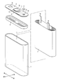
- FIG. 2 is an exploded perspective view of the sealed battery according to the present invention.
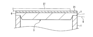
- 3 is a cross-sectional view taken along the line II of FIG. 1B.
- FIG. 4 is a top view of the sealing plate of the sealed battery according to the present invention.
- FIG. 5 is a perspective view showing a process of joining a nickel plate to an aluminum plate.
- the present invention is a method for producing a sealed battery comprising a battery can and a sealing plate formed of aluminum or an aluminum alloy that closes the opening of the battery can. Further, the method for manufacturing a sealed battery according to the present invention includes a step of preparing a strip-shaped aluminum plate formed of aluminum or an aluminum alloy, and a dissimilar metal different from the aluminum or a different metal alloy different from the aluminum alloy. A step of preparing a strip-shaped dissimilar metal plate having a width narrower than that of the aluminum plate, and a pressure-bonding step of superimposing the dissimilar metal plate on the aluminum plate along the length direction of the aluminum plate.
- a dissimilar metal body formed of a dissimilar metal or dissimilar metal alloy different from aluminum is integrally formed on the upper surface of a sealing plate made of aluminum or aluminum alloy that closes the opening of the left and right horizontally long battery cans. It is a manufacturing method of the sealed battery formed.
- the manufacturing method of the present invention provides a strip-shaped aluminum plate made of aluminum or an aluminum alloy and a strip-shaped foreign metal plate made of the above-mentioned different metal or the above-mentioned different metal alloy and having a narrower width than the aluminum plate. A member formed by stacking and press-bonding along the length direction and then cutting an aluminum plate together with a dissimilar metal plate is used as the sealing plate 3.
- the dissimilar metal body is made of nickel or nickel alloy, iron alloy such as iron or stainless steel, copper or copper alloy, or the like.
- an external lead connected to a protective circuit or an external device is joined to the dissimilar metal body by welding or soldering using a laser or the like.
- the dissimilar metal plate can be pressure-bonded to the aluminum plate by conveying the aluminum plate obtained by superimposing the dissimilar metal plates between the pair of rolling rollers in the length direction of the aluminum plate while being pressed.
- the thickness of the dissimilar metal plate material in a free state before crimping can be in the range of 10 to 25% of the thickness of the aluminum plate material.
- the dissimilar metal plate material can be handled as a single member in a free state before the pressure bonding since the belt-like dissimilar metal plate material is superimposed on the belt-shaped aluminum plate material and pressure bonded.
- the labor of component management is reduced.
- the aluminum plate is cut together with the dissimilar metal plate to form the sealing plate, so that each of the small pieces necessary for crimping the small pieces to the aluminum plate is placed on the aluminum plate.
- the battery manufacturing efficiency is improved accordingly.
- the aluminum plate material on which the different metal plate materials are overlapped is conveyed in the length direction of the aluminum plate material while being pressed between a pair of rolling rollers, the aluminum plate material after the pressure bonding is directly conveyed to the cutting process or the like and sealed.
- the battery manufacturing efficiency is further improved.
- the thickness of the dissimilar metal plate is in the range of 10 to 25% of the thickness of the aluminum plate in the free state before crimping, the thickness of the dissimilar metal body can be sufficiently secured and different external leads can be secured.
- the metal body can be appropriately welded, and the thickness of the dissimilar metal body is not excessively increased, so that the use amount of the dissimilar metal body can be suppressed.
- the thickness of the dissimilar metal plate is less than 10% of the thickness of the aluminum plate, for example, the heat when welding the external lead to the dissimilar metal body can easily escape from the dissimilar metal body to the sealing body. There is a tendency that the lead is not properly welded to the dissimilar metal body. Further, if the thickness of the dissimilar metal plate exceeds 25% of the thickness of the aluminum plate, the amount of the dissimilar metal body is increased by the amount that the dissimilar metal body becomes too thick, leading to an increase in battery cost. Tend to occur.
- the sealed battery according to the present invention has a bottomed cylindrical battery can 1 having a horizontally long opening on the upper surface and an electrode body 2 accommodated in the battery can 1. And a non-aqueous electrolyte solution, a horizontally long sealing plate 3 that closes and seals the opening of the battery can 1, and a synthetic resin insulator 5 that is disposed below the sealing plate 3.
- the left-right width dimension of the battery can 1 is, for example, 34 mm
- the vertical height dimension is, for example, 46 mm
- the front-rear thickness dimension is, for example, 4 mm.
- the sealing plate 3 is formed so that the sides 6 and 7 are linear and the sides 6 and 7 are parallel to each other.
- left and right and front and rear are directions shown in FIG. 2 and FIG. 5 described later.
- the battery can 1 is formed by, for example, deep drawing a plate material made of aluminum or an aluminum alloy
- the sealing plate 3 is formed by, for example, pressing and cutting a plate material made of aluminum or an aluminum alloy.
- the outer peripheral edge of the sealing plate 3 has a step shape in which the lower portion is recessed inward, and the bottom surface of the step is placed on the upper edge of the opening of the battery can 1, for example, from the lateral direction.
- the electrode body 2 is formed by winding a strip-shaped positive electrode and a strip-shaped negative electrode in a spiral shape with a strip-shaped separator interposed therebetween, and is formed in a flat shape as a whole.
- a cleavage vent 9 is formed on the left side of the sealing plate 3. The cleavage vent 9 is cleaved when the battery internal pressure abnormally rises to release the battery internal pressure.
- a liquid injection hole 10 for injecting a non-aqueous electrolyte into the battery can 1 is formed on the right side of the sealing plate 3, and the liquid injection hole 10 after the injection of the non-aqueous electrolyte is closed with a sealing plug 11. For example, it is sealed by a laser.
- a through hole 14 is formed in the center of the sealing plate 3 in the left-right direction, and a negative electrode terminal 15 is inserted through the through hole 14 with the insulating packing 12 interposed.
- the insulating plate 13 and the lead plate 16 are arranged vertically, and the lead plate 16 is connected to the lower end of the negative electrode terminal 15.
- the negative electrode terminal 15 is made of, for example, an iron material whose surface is plated with copper nickel.
- the insulating packing 12 and the insulating plate 13 are made of a synthetic resin molded product having insulation properties such as polypropylene, and the lead plate 16 is made of a thin plate made of nickel that is horizontally long.
- the negative electrode terminal 15 is insulated from the sealing plate 3 by the insulating packing 12.
- the insulating plate 13 extends from the negative electrode terminal 15 side toward the cleavage vent 9 side, and the lead plate 16 extends along the sealing plate 3 from the negative electrode terminal 15 side toward the cleavage vent 9 side in the lateral direction. .
- the lead plate 16 is insulated from the sealing plate 3 by the insulating plate 13.
- the lower end of the negative electrode current collector lead 18 is connected to the negative electrode of the electrode body 2, and the upper end of the negative electrode current collector lead 18 is welded to the lower surface of the lead plate 16.
- the lower end of the positive electrode current collecting lead 19 is connected to the positive electrode of the electrode body 2, and the upper end of the positive electrode current collecting lead 19 is in the space between the negative electrode terminal 15 and the liquid injection hole 10 on the lower surface of the sealing plate 3. Welded.
- the negative electrode terminal 15 has the same potential as the negative electrode of the electrode body 2, and the sealing plate 3 and the battery can 1 have the same potential as the positive electrode of the electrode body 2.
- nickel (dissimilar metal) or nickel alloy (dissimilar metal alloy) is formed in the space between the negative electrode terminal 15 and the liquid injection hole 10 on the upper surface of the sealing plate 3, as shown in FIG. 1 and FIG. 2, for example, nickel (dissimilar metal) or nickel alloy (dissimilar metal alloy) is formed.
- a nickel body (dissimilar metal body) 21 is disposed integrally with the sealing body 3.
- the nickel body 21 is joined to an external lead 27 described later.
- the nickel body 21 extends in a band shape between the sides 6 and 7 of the sealing plate 3, and the upper surface of the nickel body 21 is substantially flush with the upper surface of the sealing plate 3.
- the nickel body 21 has a lateral width dimension of, for example, 5 mm and a thickness dimension of, for example, 0.1 to 0.2 mm.
- the sealing plate 3 has a left-right width dimension of, for example, 30 mm and a thickness dimension of, for example, 0.8 mm.
- the nickel body 21 is integrated with the sealing plate 3 as follows, for example. First, a strip-shaped aluminum plate material 22 made of aluminum or an aluminum alloy, which is a material of the sealing plate 3, is prepared. In addition, a strip-like nickel plate material (dissimilar metal plate material) 23 made of nickel or a nickel alloy, which is the material of the nickel body 21, and narrower than the aluminum plate material 22 is prepared. Next, as shown in FIG. 5, the nickel plate material 23 is superposed along the length direction of the aluminum plate material 22 at a predetermined position in the left-right width direction on the upper surface of the aluminum plate material 22, and a pair of upper and lower rolling rollers 24, 25 are used. The nickel plate material 23 is pressure-bonded to the aluminum plate material 22 by being conveyed in the length direction of the aluminum plate material 22 while being sandwiched and pressurized.
- the aluminum plate material 22 is conveyed to the pressing step and the cutting step, so that the cleavage plate 9, the liquid injection hole 10, and the through hole 14 are formed at predetermined positions in the aluminum plate material 22 to which the nickel plate material 23 is pressure-bonded. And the aluminum plate material 22 is cut
- the sealing plate 3 formed as described above is used. That is, the negative electrode terminal 15, the insulating packing 12, the insulating plate 13, and the lead plate 16 are assembled to the sealing plate 3 (see FIG. 1A).
- the electrode body 2 and the insulator 5 are accommodated in the battery can 1, and the negative electrode current collecting lead 18 of the electrode body 2 is welded to the lead plate 16, and the positive electrode current collecting lead 19 of the electrode body 2 is welded to the sealing plate 3. .
- the inside of the battery can 1 is evacuated and the non-aqueous electrolyte is supplied from the injection hole 10. inject.
- the sealing plug 11 is press-fitted into the liquid injection hole 10, and the sealing plug 11 is welded to the peripheral edge of the liquid injection hole 10 of the sealing plate 3 by, for example, a laser (see FIG. 1A). Status).
- the liquid injection hole 10 is sealed with the sealing plug 11 to complete the sealed battery.
- external leads 26 and 27 for connection to an external device or a protection circuit are connected to the upper surface of the negative electrode terminal 15 and the nickel body 21 by spot welding or the like.
- the band-shaped nickel plate material 23 is superimposed on the band-shaped aluminum plate material 22 and pressed, the nickel plate material 23 is handled as a single member in a free state before pressure bonding. Can do. Thereby, for example, compared with a case where the nickel plate member 23 is cut into a large number of small pieces, and each small piece is placed on the aluminum plate member 22 and is crimped, the labor of component management is reduced.
- each piece is placed on the aluminum plate 22 as compared with the case where each piece is pressed against the aluminum plate 22. Therefore, the battery manufacturing efficiency is improved accordingly.
- the aluminum plate 22 on which the nickel plate 23 is superimposed is conveyed in the length direction of the aluminum plate 22 while being pressed between the pair of rolling rollers 24 and 25. Therefore, the aluminum plate 22 after the pressure bonding is conveyed. Can be transported to the cutting process or the like as it is to form the sealing body 3, and the manufacturing efficiency of the battery is further improved.
- the thickness of the nickel plate material 23 in a free state before crimping is in the range of 10 to 25% of the thickness of the aluminum plate material 22. If the thickness of the nickel plate material 23 is less than 10% of the thickness of the aluminum plate material 22, the nickel body 21 becomes too thin, and when the external lead 27 is welded to the nickel body 21, the heat of the welding is reduced to the nickel body. There is a tendency that the inconvenience that the external lead 27 is not properly welded to the nickel body 21 due to escape from the sealing body 21 to the sealing body 3. Further, if the thickness of the nickel plate member 23 exceeds 25% of the thickness of the aluminum plate member 22, the nickel body 21 becomes too thick, and the amount of use of the nickel body 21 increases, leading to an increase in battery cost. Tend to occur.
- the nickel body (different metal body) 21 may be formed of an iron alloy such as iron or stainless steel, or formed of copper or a copper alloy.
- the present invention it is possible to provide a manufacturing method of a sealed battery that can reduce the labor of component management accompanying the joining of dissimilar metals to the sealing plate and can improve the manufacturing efficiency of the battery, and its industrial value is great. .
Landscapes
- Chemical & Material Sciences (AREA)
- Chemical Kinetics & Catalysis (AREA)
- Electrochemistry (AREA)
- General Chemical & Material Sciences (AREA)
- Inorganic Chemistry (AREA)
- Sealing Battery Cases Or Jackets (AREA)
Abstract
本発明の密閉型電池の製造方法は、アルミニウム又はアルミニウム合金から形成された帯状のアルミニウム板材を準備する工程と、前記アルミニウムとは異なる異種金属又は前記アルミニウム合金とは異なる異種金属合金で形成され、前記アルミニウム板材よりも幅の狭い帯状の異種金属板材を準備する工程と、前記アルミニウム板材に、前記異種金属板材を、前記アルミニウム板材の長さ方向に沿って重ね合わせて圧着する圧着工程と、前記圧着工程の後に、前記アルミニウム板材を前記異種金属板材と共に切断して、前記異種金属又は前記異種金属合金から形成された異種金属体を一体化した封口板を形成する工程と、前記異種金属体を外側にして、前記封口板を、電池缶の開口に接合する工程とを含む。
Description
本発明は、電池缶と、上記電池缶の開口を塞ぐアルミニウム又はアルミニウム合金からなる封口板とを備えた密閉型電池の製造方法に関する。
リチウムイオン二次電池に代表される密閉型電池は、各種携帯用電子機器の電源として需要が増大しており、さらなる軽量化が求められている。このため最近では、電池の軽量化のため、アルミニウム又はアルミニウム合金等の軽金属で形成された電池ケースが用いられている。電池ケースは、電池缶と、その電池缶の開口を塞ぐ封口板とを備えている。通常、封口板は、ニッケル又はその合金、鉄又はその合金、銅又はその合金等で形成され、その封口板には外部リードが接続される。
しかし、アルミニウム又はアルミニウム合金の表面には酸化薄膜が形成されているため、ニッケル等で形成された外部リードをアルミニウム又はアルミニウム合金で形成された封口板に、レーザ等による溶接又は半田付け等によって接合することは困難である。
このため、外部リードと封口板のと接合を容易にするため、アルミニウム又はアルミニウム合金からなる封口板の上面に、アルミニウムとは異なる異種金属又は異種金属合金で形成された異種金属体を一体化することが提案されている。
上記異種金属体を一体化した封口体を用いた密閉型電池としては、例えば特許文献1ないし3に示すものがある。特許文献1および2には、アルミニウム又はアルミニウム合金で形成された封口板に、ニッケル-アルミニウムのクラッド材からなる端子を、その端子のアルミニウム面を封口板に対面させた状態で溶接して一体化することが記載されている。そして、特許文献1および2では、保護回路又は外部機器等に接続された外部リードを上記端子に溶接している。また、特許文献3には、アルミニウム製の封口板の一部に、冷間圧延接合法によってニッケルの小片を圧着して一体化し、その小片に外部リードを溶接することが記載されている。
特許文献1および2の密閉型電池では、ニッケル-アルミニウムのクラッド材からなる端子を封口板とは別に作製した後に、該端子を封口板に溶接することになるため、部品点数が増えて部品管理の手間等が増えると共に、端子の溶接作業等が必要な分だけ電池の製造効率が悪くなる。
また、特許文献3の密閉型電池では、多数のニッケルの小片を封口板とは別に作製し、各小片を、封口板の材料である帯状のアルミニウム板上の所定位置にそれぞれ載置した後に、上下一対の工具で各小片をアルミニウム板に押し付けて接合することになる。このため、小片毎の部品管理が必要になってその管理に手間等が掛かることになる。また、各小片をアルミニウム板上にそれぞれ載置する作業の分だけ、封口板にニッケルを接合するまでに時間が掛かって電池の製造効率が悪くなる。
本発明の密閉型電池の製造方法は、電池缶と、前記電池缶の開口を塞ぐアルミニウム又はアルミニウム合金から形成された封口板とを含む密閉型電池の製造方法であって、アルミニウム又はアルミニウム合金から形成された帯状のアルミニウム板材を準備する工程と、前記アルミニウムとは異なる異種金属又は前記アルミニウム合金とは異なる異種金属合金で形成され、前記アルミニウム板材よりも幅の狭い帯状の異種金属板材を準備する工程と、前記アルミニウム板材に、前記異種金属板材を、前記アルミニウム板材の長さ方向に沿って重ね合わせて圧着する圧着工程と、前記圧着工程の後に、前記アルミニウム板材を前記異種金属板材と共に切断して、前記異種金属又は前記異種金属合金から形成された異種金属体を一体化した封口板を形成する工程と、前記異種金属体を外側にして、前記封口板を、電池缶の開口に接合する工程とを含むことを特徴とする。
本発明の密閉型電池の製造方法によれば、封口板への異種金属の接合に伴う部品管理の手間等を低減できると共に、電池の製造効率を向上できる。
本発明は、電池缶と、上記電池缶の開口を塞ぐアルミニウム又はアルミニウム合金から形成された封口板とを備えた密閉型電池の製造方法である。また、本発明の密閉型電池の製造方法は、アルミニウム又はアルミニウム合金から形成された帯状のアルミニウム板材を準備する工程と、上記アルミニウムとは異なる異種金属又は上記アルミニウム合金とは異なる異種金属合金で形成され、上記アルミニウム板材よりも幅の狭い帯状の異種金属板材を準備する工程と、上記アルミニウム板材に、上記異種金属板材を、上記アルミニウム板材の長さ方向に沿って重ね合わせて圧着する圧着工程と、上記圧着工程の後に、上記アルミニウム板材を上記異種金属板材と共に切断して、上記異種金属又は上記異種金属合金から形成された異種金属体を一体化した封口板を形成する工程と、上記異種金属体を外側にして、上記封口板を、電池缶の開口に接合する工程とを含むことを特徴とする。
より具体的には、本発明は、左右横長の電池缶の開口を塞ぐアルミニウム又はアルミニウム合金からなる封口板の上面に、アルミニウムとは異なる異種金属又は異種金属合金で形成された異種金属体を一体化してなる密閉型電池の製造方法である。また、本発明の製造方法は、アルミニウム又はアルミニウム合金からなる帯状のアルミニウム板材に、上記異種金属又は上記異種金属合金からなり、アルミニウム板材よりも幅の狭い帯状の異種金属板材を、アルミニウム板材の長さ方向に沿って重ね合わせて圧着した後、アルミニウム板材を異種金属板材と共に切断して形成した部材を封口板3として用いることを特徴とする。
上記異種金属体は、ニッケル又はニッケル合金、鉄又はステンレス鋼等の鉄合金、銅又は銅合金等で形成される。異種金属体には、例えば、保護回路又は外部機器等に接続された外部リードが、レーザ等による溶接又は半田付け等によって接合される。
また、上記異種金属板材を重ね合わせたアルミニウム板材を、一対の圧延ローラで挟んで加圧しながらアルミニウム板材の長さ方向に搬送することで、異種金属板材をアルミニウム板材に圧着することができる。
また、圧着前の自由状態で異種金属板材の厚さは、アルミニウム板材の厚さの10~25%の範囲内とすることができる。
本発明に係る密閉型電池の製造方法においては、帯状の異種金属板材を帯状のアルミニウム板材に重ね合わせて圧着するので、圧着前の自由状態で異種金属板材を一つの部材として取り扱うことができる。これによって、例えば異種金属板材を多数の小片に切断して、各小片をアルミニウム板材上にそれぞれ載置して圧着する場合に比べて、部品管理の手間が軽減される。
また、本発明では、アルミニウム板材を異種金属板材と共に切断して封口板を形成するので、前述の各小片をアルミニウム板材にそれぞれ圧着する場合には必要であった各小片をアルミニウム板材上に載置する作業等がなくなり、その分だけ電池の製造効率が向上する。
さらに、異種金属板材を重ね合わせたアルミニウム板材を、一対の圧延ローラで挟んで加圧しながらアルミニウム板材の長さ方向に搬送すると、その圧着後のアルミニウム板材を切断工程等にそのまま搬送して封口体を形成でき、電池の製造効率がより向上する。
また、圧着前の自由状態で異種金属板材の厚さが、アルミニウム板材の厚さの10~25%の範囲内であると、異種金属体の厚さを十分に確保できて、外部リードを異種金属体に適正に溶接できると共に、その異種金属体の厚さが過剰に大きくならず、異種金属体の使用量を抑えることができる。
即ち、異種金属板材の厚さがアルミニウム板材の厚さの10%未満であると、例えば、外部リードを異種金属体に溶接する際の熱が異種金属体から封口体に逃げ易くなって、外部リードが異種金属体に適正に溶接されなくなる不都合が生じる傾向がある。また、異種金属板材の厚さがアルミニウム板材の厚さの25%を越えると、異種金属体が厚くなり過ぎる分だけ、異種金属体の使用量が増えて電池のコスト上昇を招いてしまう不都合が生じる傾向がある。
以下、図面に基づき本発明の密閉型電池の製造方法を説明する。本発明に係る密閉型電池は、図1A、Bおよび図2に示すように、上面に左右横長の開口を有する有底筒形状の電池缶1と、電池缶1内に収容された電極体2および非水電解液と、電池缶1の開口を塞いで密封する左右横長の封口板3と、封口板3の下側に配置される合成樹脂製の絶縁体5とを備えている。電池缶1の左右幅寸法は例えば34mm、上下高さ寸法は例えば46mm、前後厚み寸法は例えば4mmである。封口板3は、側辺6・7がそれぞれ直線状、且つ、側辺6・7どうしが平行になるように形成される。
本明細書で左右および前後とは、図2および後述する図5に示す方向とする。
電池缶1は、アルミニウム又はアルミニウム合金からなる板材を、例えば深絞り加工することで形成され、封口板3は、アルミニウム又はアルミニウム合金からなる板材を、例えばプレスおよび切断加工することで形成される。封口板3の外周縁は、図3に示すように、下部が内方に凹む段差形状になっており、その段差の下面を電池缶1の開口上縁に載せた状態で横方向から例えばレーザ光8を照射することで、封口板3が電池缶1にシーム溶接される。
電極体2は、図2に示すように、帯状の正極と帯状の負極とを帯状のセパレータを挟んで渦巻状に巻回してなり、全体が扁平状に形成される。封口板3の左側には開裂ベント9が形成される。開裂ベント9は、電池内圧が異常上昇したときに開裂して電池内圧を解放する。封口板3の右側には、電池缶1内に非水電解液を注入するための注液孔10が形成され、非水電解液の注入後の注液孔10が、封止栓11で塞がれて、例えばレーザによって封口される。
封口板3の左右方向の中央には、図1に示すように、貫通孔14が形成されており、貫通孔14には負極端子15が絶縁パッキング12を介在させた状態で挿通している。封口板3の下側には、絶縁板13およびリード板16が上下に配置してあり、負極端子15の下端にリード板16が接続される。負極端子15は、例えば表面に銅ニッケルメッキを施した鉄材等からなる。絶縁パッキング12と絶縁板13とは、例えばポリプロピレン等の絶縁性を有する合成樹脂成形品からなり、リード板16は、左右横長の例えばニッケル製の薄板からなる。負極端子15は、絶縁パッキング12によって封口板3から絶縁される。絶縁板13は、負極端子15側から開裂ベント9側へ向けて伸びており、リード板16は、封口板3に沿って負極端子15側から開裂ベント9側へ向けて横方向に伸びている。絶縁板13によってリード板16が封口板3から絶縁される。
電極体2の負極には、負極集電リード18の下端が接続されており、負極集電リード18の上端がリード板16の下面に溶接される。電極体2の正極には、正極集電リード19の下端が接続されており、正極集電リード19の上端が、封口板3の下面において負極端子15と注液孔10との間のスペースに溶接される。これにて、負極端子15が電極体2の負極と同電位になり、封口板3と電池缶1とが電極体2の正極と同電位になる。
封口板3の上面において負極端子15と注液孔10との間のスペースには、図1および図2に示すように、例えばニッケル(異種金属)又はニッケル合金(異種金属合金)で形成されたニッケル体(異種金属体)21が、封口体3と一体化して配置されている。ニッケル体21は、後述する外部リード27が接合される。ニッケル体21は、封口板3の側辺6・7間にわたって帯状に伸びており、ニッケル体21の上面が封口板3の上面とほぼ面一になっている。ニッケル体21は、左右幅寸法が例えば5mm、厚み寸法が例えば0.1~0.2mmである。封口板3は、左右幅寸法が例えば30mm、厚み寸法が例えば0.8mmである。
ニッケル体21は、例えば、次のようにして封口板3に一体化する。先ず、封口板3の材料であるアルミニウム又はアルミニウム合金からなる帯状のアルミニウム板材22を準備する。また、ニッケル体21の材料であるニッケル又はニッケル合金からなり、アルミニウム板材22よりも幅の狭い帯状のニッケル板材(異種金属板材)23を準備する。次に、図5に示すように、アルミニウム板材22の上面における左右幅方向の所定位置に、ニッケル板材23をアルミニウム板材22の長さ方向に沿って重ね合わせ、上下一対の圧延ローラ24・25で挟んで加圧しながらアルミニウム板材22の長さ方向に搬送することで、ニッケル板材23をアルミニウム板材22に圧着する。
この後にアルミニウム板材22をプレス工程および切断工程に搬送することよって、ニッケル板材23を圧着したアルミニウム板材22には、開裂ベント9と注液孔10と貫通孔14とがそれぞれ所定の位置に形成され、且つ、アルミニウム板材22がニッケル板材23と共に図2に示す所定の形状に切断される。これにてニッケル体21が一体化した封口板3の作製が完了する。
電池の組み立てに際しては、上記の要領で形成した封口板3が用いられる。即ち、封口板3に対して、負極端子15と絶縁パッキング12と絶縁板13とリード板16とを組み付ける(図1A参照)。次いで、電極体2および絶縁体5を電池缶1内に収容し、電極体2の負極集電リード18をリード板16に、電極体2の正極集電リード19を封口板3にそれぞれ溶接する。
次に、電池缶1の開口に、ニッケル体21を外側に向けて封口板3を、例えばレーザでシーム溶接した後に、電池缶1内を真空減圧して注液孔10から非水電解液を注入する。非水電解液の注入完了後に、封止栓11を注液孔10に圧入し、封止栓11を封口板3の注液孔10の周縁部に、例えばレーザ等により溶接する(図1Aの状態)。これによって、注液孔10が封止栓11で密封されて密閉型電池が完成する。
この後、図4に示すように、例えば、外部機器又は保護回路に接続するための外部リード26・27が、負極端子15およびニッケル体21の上面にそれぞれスポット溶接等で接続される。
以上のように本発明の密閉型電池の製造方法では、帯状のニッケル板材23を帯状のアルミニウム板材22に重ね合わせて圧着するので、圧着前の自由状態でニッケル板材23を一つの部材として取り扱うことができる。これによって、例えばニッケル板材23を多数の小片に切断して、各小片をアルミニウム板材22上にそれぞれ載置して圧着する場合に比べて、部品管理の手間が軽減される。
また、本発明では、アルミニウム板材22をニッケル板材23と共に切断して封口板3を形成するので、前述の各小片をアルミニウム板材22にそれぞれ圧着する場合に比べ、各小片をアルミニウム板材22上に載置する作業がなくなり、その分だけ電池の製造効率が向上する。
また、本発明では、ニッケル板材23を重ね合わせたアルミニウム板材22を、一対の圧延ローラ24・25で挟んで加圧しながらアルミニウム板材22の長さ方向に搬送するので、その圧着後のアルミニウム板材22を切断工程等にそのまま搬送して封口体3を形成でき、電池の製造効率がより向上する。
圧着前の自由状態でニッケル板材23の厚さは、アルミニウム板材22の厚さの10~25%の範囲内であることが望ましい。ニッケル板材23の厚さがアルミニウム板材22の厚さの10%未満であると、ニッケル体21が薄くなり過ぎて、外部リード27をニッケル体21に溶接する際に、その溶接の熱がニッケル体21から封口体3に逃げて、外部リード27がニッケル体21に適正に溶接されなくなる不都合が生じる傾向がある。また、ニッケル板材23の厚さがアルミニウム板材22の厚さの25%を越えると、ニッケル体21が厚くなり過ぎて、ニッケル体21の使用量が増えて電池のコスト上昇を招いてしまう不都合が生じる傾向がある。
ニッケル体(異種金属体)21は、鉄又はステンレス等の鉄合金で形成されたもの、又は銅又は銅合金で形成されたもの等であってもよい。
本発明は、その趣旨を逸脱しない範囲で、上記以外の形態としても実施が可能である。本出願に開示された実施形態は一例であって、これらに限定はされない。本発明の範囲は、上述の明細書の記載よりも、添付されている請求の範囲の記載を優先して解釈され、請求の範囲と均等の範囲内での全ての変更は、請求の範囲に含まれるものである。
本発明によれば、封口板への異種金属の接合に伴う部品管理の手間等を低減できると共に、電池の製造効率を向上できる密閉型電池の製造方法を提供でき、その産業上の価値は大きい。
1 電池缶
3 封口板
21 ニッケル体
22 アルミニウム板材
23 ニッケル板材
24、25 圧延ローラ
3 封口板
21 ニッケル体
22 アルミニウム板材
23 ニッケル板材
24、25 圧延ローラ
Claims (5)
- 電池缶と、前記電池缶の開口を塞ぐアルミニウム又はアルミニウム合金から形成された封口板とを含む密閉型電池の製造方法であって、
アルミニウム又はアルミニウム合金から形成された帯状のアルミニウム板材を準備する工程と、
前記アルミニウムとは異なる異種金属又は前記アルミニウム合金とは異なる異種金属合金で形成され、前記アルミニウム板材よりも幅の狭い帯状の異種金属板材を準備する工程と、
前記アルミニウム板材に、前記異種金属板材を、前記アルミニウム板材の長さ方向に沿って重ね合わせて圧着する圧着工程と、
前記圧着工程の後に、前記アルミニウム板材を前記異種金属板材と共に切断して、前記異種金属又は前記異種金属合金から形成された異種金属体を一体化した封口板を形成する工程と、
前記異種金属体を外側にして、前記封口板を、電池缶の開口に接合する工程と、
を含むことを特徴とする密閉型電池の製造方法。 - 前記圧着工程において、前記異種金属板材を重ね合わせた前記アルミニウム板材を、一対の圧延ローラで挟んで加圧しながら前記アルミニウム板材の長さ方向に搬送して、前記異種金属板材を前記アルミニウム板材に圧着する請求項1に記載の密閉型電池の製造方法。
- 前記圧着工程の前の自由状態における前記異種金属板材の厚さが、前記アルミニウム板材の厚さの10~25%の範囲内である請求項1に記載の密閉型電池の製造方法。
- 前記異種金属が、ニッケル、鉄および銅からなる群から選択されるいずれか1種の金属である請求項1に記載の密閉型電池の製造方法。
- 前記異種金属合金が、ニッケル合金、鉄合金および銅合金からなる群から選択されるいずれか1種の合金である請求項1に記載の密閉型電池の製造方法。
Applications Claiming Priority (2)
| Application Number | Priority Date | Filing Date | Title |
|---|---|---|---|
| JP2008-151931 | 2008-06-10 | ||
| JP2008151931A JP2011192386A (ja) | 2008-06-10 | 2008-06-10 | 密閉型電池の製造方法 |
Publications (1)
| Publication Number | Publication Date |
|---|---|
| WO2009151007A1 true WO2009151007A1 (ja) | 2009-12-17 |
Family
ID=41416713
Family Applications (1)
| Application Number | Title | Priority Date | Filing Date |
|---|---|---|---|
| PCT/JP2009/060340 Ceased WO2009151007A1 (ja) | 2008-06-10 | 2009-06-05 | 密閉型電池の製造方法 |
Country Status (2)
| Country | Link |
|---|---|
| JP (1) | JP2011192386A (ja) |
| WO (1) | WO2009151007A1 (ja) |
Cited By (3)
| Publication number | Priority date | Publication date | Assignee | Title |
|---|---|---|---|---|
| WO2013107732A1 (de) * | 2012-01-19 | 2013-07-25 | Robert Bosch Gmbh | Gehäusedeckel für ein batteriegehäuse sowie ein verfahren zur herstellung des gehäusedeckels |
| JP2014182950A (ja) * | 2013-03-19 | 2014-09-29 | Gs Yuasa Corp | 蓄電素子 |
| EP4166268A4 (en) * | 2020-08-18 | 2024-01-17 | LG Energy Solution, Ltd. | WELDING DEVICE FOR PRODUCING A SECONDARY BATTERY AND WELDING METHOD THEREFOR |
Citations (5)
| Publication number | Priority date | Publication date | Assignee | Title |
|---|---|---|---|---|
| JP2003157904A (ja) * | 2001-11-22 | 2003-05-30 | Gs-Melcotec Co Ltd | リチウムイオン電池及び電池装置 |
| JP2004311401A (ja) * | 2002-12-18 | 2004-11-04 | Samsung Sdi Co Ltd | 二次電池 |
| JP2006051523A (ja) * | 2004-08-12 | 2006-02-23 | Neomax Material:Kk | 導電部品用クラッド材およびその製造方法 |
| JP2006147574A (ja) * | 2004-11-18 | 2006-06-08 | Samsung Sdi Co Ltd | 二次電池及びその形成方法 |
| JP2007335219A (ja) * | 2006-06-15 | 2007-12-27 | Nec Tokin Corp | 密閉型電池 |
-
2008
- 2008-06-10 JP JP2008151931A patent/JP2011192386A/ja not_active Withdrawn
-
2009
- 2009-06-05 WO PCT/JP2009/060340 patent/WO2009151007A1/ja not_active Ceased
Patent Citations (5)
| Publication number | Priority date | Publication date | Assignee | Title |
|---|---|---|---|---|
| JP2003157904A (ja) * | 2001-11-22 | 2003-05-30 | Gs-Melcotec Co Ltd | リチウムイオン電池及び電池装置 |
| JP2004311401A (ja) * | 2002-12-18 | 2004-11-04 | Samsung Sdi Co Ltd | 二次電池 |
| JP2006051523A (ja) * | 2004-08-12 | 2006-02-23 | Neomax Material:Kk | 導電部品用クラッド材およびその製造方法 |
| JP2006147574A (ja) * | 2004-11-18 | 2006-06-08 | Samsung Sdi Co Ltd | 二次電池及びその形成方法 |
| JP2007335219A (ja) * | 2006-06-15 | 2007-12-27 | Nec Tokin Corp | 密閉型電池 |
Cited By (3)
| Publication number | Priority date | Publication date | Assignee | Title |
|---|---|---|---|---|
| WO2013107732A1 (de) * | 2012-01-19 | 2013-07-25 | Robert Bosch Gmbh | Gehäusedeckel für ein batteriegehäuse sowie ein verfahren zur herstellung des gehäusedeckels |
| JP2014182950A (ja) * | 2013-03-19 | 2014-09-29 | Gs Yuasa Corp | 蓄電素子 |
| EP4166268A4 (en) * | 2020-08-18 | 2024-01-17 | LG Energy Solution, Ltd. | WELDING DEVICE FOR PRODUCING A SECONDARY BATTERY AND WELDING METHOD THEREFOR |
Also Published As
| Publication number | Publication date |
|---|---|
| JP2011192386A (ja) | 2011-09-29 |
Similar Documents
| Publication | Publication Date | Title |
|---|---|---|
| US10510997B2 (en) | Film-covered battery | |
| US9525228B2 (en) | Battery terminal, method for manufacturing battery terminal, and battery | |
| CN101079475B (zh) | 密封电池 | |
| US10622597B2 (en) | Battery cell having outer edge sealed portion with sealed lines and battery cell sealing apparatus for manufacture thereof | |
| US9882192B2 (en) | Interconnection assemblies and methods for forming the interconnection assemblies in a battery module | |
| CN210120177U (zh) | 电池模块、包含电池模块的电池组和包含电池组的车辆 | |
| JP5587061B2 (ja) | 抵抗溶接用通電ブロック、この通電ブロックを用いた密閉電池の製造方法及び密閉電池 | |
| KR101637891B1 (ko) | 둘 이상의 부재들로 이루어진 전지케이스를 포함하는 각형 전지셀 | |
| CN103534838B (zh) | 电池用负极端子和电池用负极端子的制造方法 | |
| US20150214516A1 (en) | Secondary battery | |
| US8530068B2 (en) | Square battery and manufacturing method of the same | |
| KR101294931B1 (ko) | 전지용 부극 단자 | |
| KR20250039335A (ko) | 이차 전지 및 그의 제조 방법 | |
| JP2020518963A (ja) | 電極タブリード結合部に適用されるプラスチック部材を含む電極組立体及びこれを含む二次電池 | |
| KR102309416B1 (ko) | 박판을 이용한 리드 단선을 개선하는 파우치형 이차전지 및 그 제조방법 | |
| KR102157495B1 (ko) | 파우치형 배터리 셀 및 그 제조방법 | |
| JP2016085875A (ja) | 蓄電素子、電源モジュール及び蓄電素子の製造方法 | |
| JP2014059954A (ja) | 角型電池缶及びその製造方法 | |
| KR101520168B1 (ko) | 파우치형 리튬 이차 전지 | |
| JP7599967B2 (ja) | 端子部品、二次電池および組電池 | |
| JP2015153513A (ja) | ラミネート外装電池 | |
| KR101753938B1 (ko) | 전기 절연성이 향상된 이차전지의 제조방법 | |
| KR100516768B1 (ko) | 전극탭 병렬결합구조를 갖는 이차전지 및 그 전극탭 결합 방법 | |
| CN107591555B (zh) | 二次电池 | |
| KR101182643B1 (ko) | 각형 전지 케이스의 제조방법 |
Legal Events
| Date | Code | Title | Description |
|---|---|---|---|
| 121 | Ep: the epo has been informed by wipo that ep was designated in this application |
Ref document number: 09762437 Country of ref document: EP Kind code of ref document: A1 |
|
| NENP | Non-entry into the national phase |
Ref country code: DE |
|
| 122 | Ep: pct application non-entry in european phase |
Ref document number: 09762437 Country of ref document: EP Kind code of ref document: A1 |
|
| NENP | Non-entry into the national phase |
Ref country code: JP |