WO2009145265A1 - 電子機器 - Google Patents
電子機器 Download PDFInfo
- Publication number
- WO2009145265A1 WO2009145265A1 PCT/JP2009/059791 JP2009059791W WO2009145265A1 WO 2009145265 A1 WO2009145265 A1 WO 2009145265A1 JP 2009059791 W JP2009059791 W JP 2009059791W WO 2009145265 A1 WO2009145265 A1 WO 2009145265A1
- Authority
- WO
- WIPO (PCT)
- Prior art keywords
- light
- light emitting
- light receiving
- unit
- housing
- Prior art date
- Legal status (The legal status is an assumption and is not a legal conclusion. Google has not performed a legal analysis and makes no representation as to the accuracy of the status listed.)
- Ceased
Links
Images



Classifications
-
- H—ELECTRICITY
- H04—ELECTRIC COMMUNICATION TECHNIQUE
- H04M—TELEPHONIC COMMUNICATION
- H04M1/00—Substation equipment, e.g. for use by subscribers
- H04M1/02—Constructional features of telephone sets
- H04M1/0202—Portable telephone sets, e.g. cordless phones, mobile phones or bar type handsets
- H04M1/0206—Portable telephones comprising a plurality of mechanically joined movable body parts, e.g. hinged housings
- H04M1/0208—Portable telephones comprising a plurality of mechanically joined movable body parts, e.g. hinged housings characterized by the relative motions of the body parts
- H04M1/0225—Rotatable telephones, i.e. the body parts pivoting to an open position around an axis perpendicular to the plane they define in closed position
-
- G—PHYSICS
- G01—MEASURING; TESTING
- G01B—MEASURING LENGTH, THICKNESS OR SIMILAR LINEAR DIMENSIONS; MEASURING ANGLES; MEASURING AREAS; MEASURING IRREGULARITIES OF SURFACES OR CONTOURS
- G01B11/00—Measuring arrangements characterised by the use of optical techniques
- G01B11/26—Measuring arrangements characterised by the use of optical techniques for measuring angles or tapers; for testing the alignment of axes
-
- G—PHYSICS
- G01—MEASURING; TESTING
- G01D—MEASURING NOT SPECIALLY ADAPTED FOR A SPECIFIC VARIABLE; ARRANGEMENTS FOR MEASURING TWO OR MORE VARIABLES NOT COVERED IN A SINGLE OTHER SUBCLASS; TARIFF METERING APPARATUS; MEASURING OR TESTING NOT OTHERWISE PROVIDED FOR
- G01D5/00—Mechanical means for transferring the output of a sensing member; Means for converting the output of a sensing member to another variable where the form or nature of the sensing member does not constrain the means for converting; Transducers not specially adapted for a specific variable
- G01D5/26—Mechanical means for transferring the output of a sensing member; Means for converting the output of a sensing member to another variable where the form or nature of the sensing member does not constrain the means for converting; Transducers not specially adapted for a specific variable characterised by optical transfer means, i.e. using infrared, visible, or ultraviolet light
- G01D5/32—Mechanical means for transferring the output of a sensing member; Means for converting the output of a sensing member to another variable where the form or nature of the sensing member does not constrain the means for converting; Transducers not specially adapted for a specific variable characterised by optical transfer means, i.e. using infrared, visible, or ultraviolet light with attenuation or whole or partial obturation of beams of light
- G01D5/34—Mechanical means for transferring the output of a sensing member; Means for converting the output of a sensing member to another variable where the form or nature of the sensing member does not constrain the means for converting; Transducers not specially adapted for a specific variable characterised by optical transfer means, i.e. using infrared, visible, or ultraviolet light with attenuation or whole or partial obturation of beams of light the beams of light being detected by photocells
- G01D5/347—Mechanical means for transferring the output of a sensing member; Means for converting the output of a sensing member to another variable where the form or nature of the sensing member does not constrain the means for converting; Transducers not specially adapted for a specific variable characterised by optical transfer means, i.e. using infrared, visible, or ultraviolet light with attenuation or whole or partial obturation of beams of light the beams of light being detected by photocells using displacement encoding scales
- G01D5/3473—Circular or rotary encoders
-
- G—PHYSICS
- G06—COMPUTING OR CALCULATING; COUNTING
- G06F—ELECTRIC DIGITAL DATA PROCESSING
- G06F1/00—Details not covered by groups G06F3/00 - G06F13/00 and G06F21/00
- G06F1/16—Constructional details or arrangements
- G06F1/1613—Constructional details or arrangements for portable computers
- G06F1/1615—Constructional details or arrangements for portable computers with several enclosures having relative motions, each enclosure supporting at least one I/O or computing function
- G06F1/1622—Constructional details or arrangements for portable computers with several enclosures having relative motions, each enclosure supporting at least one I/O or computing function with enclosures rotating around an axis perpendicular to the plane they define or with ball-joint coupling, e.g. PDA with display enclosure orientation changeable between portrait and landscape by rotation with respect to a coplanar body enclosure
-
- G—PHYSICS
- G06—COMPUTING OR CALCULATING; COUNTING
- G06F—ELECTRIC DIGITAL DATA PROCESSING
- G06F1/00—Details not covered by groups G06F3/00 - G06F13/00 and G06F21/00
- G06F1/16—Constructional details or arrangements
- G06F1/1613—Constructional details or arrangements for portable computers
- G06F1/1633—Constructional details or arrangements of portable computers not specific to the type of enclosures covered by groups G06F1/1615 - G06F1/1626
- G06F1/1675—Miscellaneous details related to the relative movement between the different enclosures or enclosure parts
- G06F1/1677—Miscellaneous details related to the relative movement between the different enclosures or enclosure parts for detecting open or closed state or particular intermediate positions assumed by movable parts of the enclosure, e.g. detection of display lid position with respect to main body in a laptop, detection of opening of the cover of battery compartment
-
- H—ELECTRICITY
- H04—ELECTRIC COMMUNICATION TECHNIQUE
- H04M—TELEPHONIC COMMUNICATION
- H04M1/00—Substation equipment, e.g. for use by subscribers
- H04M1/02—Constructional features of telephone sets
- H04M1/0202—Portable telephone sets, e.g. cordless phones, mobile phones or bar type handsets
- H04M1/0206—Portable telephones comprising a plurality of mechanically joined movable body parts, e.g. hinged housings
- H04M1/0241—Portable telephones comprising a plurality of mechanically joined movable body parts, e.g. hinged housings using relative motion of the body parts to change the operational status of the telephone set, e.g. switching on/off, answering incoming call
-
- H—ELECTRICITY
- H04—ELECTRIC COMMUNICATION TECHNIQUE
- H04M—TELEPHONIC COMMUNICATION
- H04M2250/00—Details of telephonic subscriber devices
- H04M2250/12—Details of telephonic subscriber devices including a sensor for measuring a physical value, e.g. temperature or motion
Definitions
- the present invention relates to an electronic device such as a mobile phone.
- one housing is provided with a light emitting / receiving portion (light emitting portion and light receiving portion), and the other housing has a plurality of reflections having different reflection efficiencies.
- a technique for detecting a relative rotational position between two housings by providing a portion and detecting a level of light reflected by a reflecting portion is known (for example, see Patent Document 1 below).
- an object of the present invention is to provide an electronic device that can optically detect a relative rotational position between two housings without using a difference in reflection efficiency among a plurality of reflecting portions. To do.
- the present invention includes a first light emitting unit that emits light, a first housing on which the first light emitting unit is mounted, a first light receiving unit that receives light, the first light receiving unit and By detecting the presence or absence of reception of light emitted from the first light-emitting unit in the first light-receiving unit, and a second case that is coupled to the first case so as to be rotatable about a rotation axis, A detection unit configured to detect a rotational position of the second housing with respect to the first housing, wherein the first light emitting unit has a first circumference around the rotation axis in the first housing.
- the first light receiving portion is disposed on a second circumference of the second housing that faces the first circumference and is located on a second circumference around the rotation axis. .
- the second casing is held by the first casing at a plurality of rotational positions at which the rotation angle of the second casing with respect to the first casing is a multiple of a preset setting angle.
- the first light emitting unit is arranged at a part or all of a plurality of positions that are multiples of the set angle on the first circumference, and the first light receiving unit is arranged on the second circumference.
- the first light receiving unit is disposed at a part or all of a plurality of positions that are multiples of the set angle in the first light emitting unit at an arbitrary rotational position of the plurality of rotational positions. It is preferable that the arrangement pattern is arranged so that the arrangement pattern of the first light emitting unit at the other rotation position among the plurality of rotation positions does not take the same arrangement pattern.
- an integer obtained by dividing 360 degrees by the set angle is an integer N
- the number of the first light emitting units arranged at a position that is a multiple of the set angle on the first circumference is the first.
- the number N of the first light receiving portions arranged at a position that is a multiple of the set angle on the second circumference is the second number R.
- the number L and the second number R are preferably set so as to satisfy the relationship shown in the following formulas 1 and 2.
- the integer N, the first number L, and the second number R are set so as to further satisfy the relationship represented by the following Expression 3.
- Expression 3 L + R ⁇ N + 1
- a signal is transmitted from the first casing to the second casing by receiving the light emitted from the first light emitting section by the first light receiving section.
- the second light emitting unit mounted at a position overlapping the rotation axis in the second housing, and the second light emitting unit mounted at a position overlapping the rotation shaft in the first housing and facing the second light emitting unit.
- a second light receiving portion disposed, and the second light receiving portion receives light emitted from the second light emitting portion, whereby a signal is transmitted from the second housing to the first housing. It is preferred that
- the present invention also provides a first light emitting unit that emits light, a third light receiving unit that receives light, a first housing in which the first light emitting unit and the third light receiving unit are mounted, and light emission.
- the third light emitting unit, the first light receiving unit for receiving light, the third light emitting unit and the first light receiving unit are mounted and connected to the first housing so as to be rotatable about a rotation axis. And whether the first light receiving unit receives light emitted from the first light emitting unit or whether the third light receiving unit receives light emitted from the third light emitting unit.
- a detection unit that detects a rotational position of the second housing relative to the first housing by detecting and transmits and receives a signal between the first housing and the second housing;
- the first light emitting unit is disposed on a first circumference around the rotation axis in the first housing.
- the first light receiving unit is disposed on the second circumference of the second housing so as to face the first circumference and have the rotation axis as a center.
- Two housings are arranged on a third circumference centered on the rotation axis, and the third light receiving portion is opposed to the third circumference in the first housing and has the rotation axis
- the present invention relates to an electronic device disposed on a fourth circumference as a center.
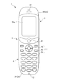
- FIG. 1 is a front view showing a cellular phone 1 according to a first embodiment of the present invention in a state where an operation unit side body 2 and a display unit side body 3 are opened.
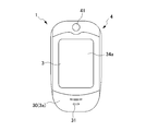
- FIG. 2 is a front view showing the cellular phone 1 shown in FIG. 1 in a state where an operation unit side body 2 and a display unit side body 3 are closed.
- the figure which shows typically the arrangement position of the 1st light emission part 51 and the 2nd light-receiving part 62 in the operation part side housing
- FIG. 1 Virtually expanding the first circumference C1 linearly along the extending direction D1 and expanding the second circumference C2 linearly along the extending direction D2. is there. It is a figure (corresponding figure of Drawing 2) showing typically cellular phone 1 in a closed state (the 1st rotation position). It is a figure which shows the state (2nd rotation position) which rotated the display part side housing
- FIG. It is a figure which shows the state (4th rotation position) which rotated the display part side housing
- FIG. It is a functional block diagram which shows the function of the mobile telephone of 1st Embodiment.
- 3 is a functional block diagram in a processing unit 70.
- FIG. It is a figure (corresponding to FIG. 3) schematically showing a configuration relating to transmission / reception of light in the mobile phone according to the second embodiment of the present invention.
- FIG. 1 is a front view showing the cellular phone 1 according to the first embodiment of the present invention in a state where the operation unit side body 2 and the display unit side body 3 are opened.
- FIG. 2 is a front view showing the cellular phone 1 shown in FIG. 1 in a state in which the operation unit side body 2 and the display unit side body 3 are closed.
- the mobile phone 1 according to the first embodiment includes an operation unit side housing 2 that is a first housing and a display unit side housing 3 that is a second housing. .
- the mobile phone 1 according to the present embodiment is a so-called rotary (turn-type) mobile phone 1 in which the operation unit side body 2 and the display unit side body 3 are overlapped (see the paper surfaces of FIGS. 1 and 2).
- One housing can be rotated around a rotation shaft 41 extending in the penetrating direction. That is, the upper end portion of the operation unit side body 2 and the lower end portion of the display unit side body 3 are coupled to each other so as to be rotatable about the rotation shaft 41 via the coupling portion 4 including the rotation shaft 41.
- the mobile phone 1 of the present embodiment is configured to be able to relatively move the operation unit side body 2 and the display unit side body 3 connected via the connection unit 4. More specifically, the mobile phone 1 includes a state in which the operation unit side body 2 and the display unit side body 3 are opened (open state, see FIG. 1), an operation unit side body 2 and the display unit side body 3. Can be changed to a closed state (closed state, see FIG. 2).
- the closed state is a state in which the front surface 2a of the operation unit side body 2 and the back surface 3b (see FIG. 4) of the display unit side body 3 overlap each other.
- a state other than the closed state is called an open state.
- the outer surface of the operation unit side body 2 is constituted by a front case 21 that forms the front surface 2a side and a rear case (not shown) that forms the back surface side.
- the operation unit side body 2 exposes the operation key group 11 and the voice input unit 12 as a microphone to which the voice uttered by the user of the mobile phone 1 is input on the front case 21 side. Configured.
- the operation key group 11 includes a function setting operation key 13 for operating various functions such as various settings, a telephone book function, and a mail function, and an input operation key 14 for inputting a telephone number and characters such as mail. And a determination operation key 15 for performing determination in various operations, scrolling in the up / down / left / right directions, and the like.
- Each key constituting the operation key group 11 has a predetermined function according to the open / close state of the operation unit side body 2 and the display unit side body 3, various modes, or the type of the activated application. Is assigned (key assignment). Then, when the user presses each key, an operation corresponding to the function assigned to each key is executed.
- the voice input unit 12 is disposed on the outer end side opposite to the connecting unit 4 side in the longitudinal direction of the operation unit side body 2. That is, the voice input unit 12 is arranged on one outer end side in the opened state of the mobile phone 1.
- the outer surface of the display unit side body 3 includes a front case 30 that forms the front surface 3a side and a rear case 32 that forms the back surface 3b (see FIG. 4) side.
- the display unit side body 3 is arranged on the front case 30 side so that the main display unit 34a for displaying various information and the audio output unit 31 for outputting the voice of the other party of the call are exposed. Composed.
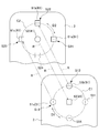
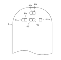
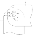
- FIG. 3 schematically shows the arrangement positions of the first light emitting unit 51 and the second light receiving unit 62 in the operation unit side body 2 and the arrangement positions of the first light receiving unit 61 and the second light emitting unit 52 in the display unit side body 3.
- FIG. 4 virtually expands the first circumference C1 linearly along the extending direction D1, and expands the second circumference C2 linearly along the extending direction D2.
- a first light emitting unit 51 and a second light receiving unit 62 are mounted on the operation unit side body 2.
- the 1st light emission part 51 is a site
- the first light emitting unit 51 is disposed on the first circumference C ⁇ b> 1 centering on the rotation shaft 41 in the operation unit side body 2.
- the second light receiving unit 62 is a part that receives light, and includes, for example, an optical sensor.
- the second light receiving unit 62 is disposed at a position overlapping the rotation shaft 41 in the operation unit side body 2.
- a first light receiving unit 61 and a second light emitting unit 52 are mounted on the display unit side body 3.
- the first light receiving unit 61 is a part that receives light, and includes, for example, an optical sensor.
- the first light receiving unit 61 is disposed on the second circumference C ⁇ b> 2 in the display unit side body 3.
- the second circumference C2 is centered on the rotation shaft 41 and faces the first circumference C1.
- the 2nd light emission part 52 is a site
- the second light emitting unit 52 is disposed in the display unit side body 3 at a position overlapping the rotation shaft 41 and facing the second light receiving unit 62.
- a rotational position detector (detector) 71 (see FIG. 6) is provided.
- the rotation position detection unit 71 detects the presence or absence of light R emitted from the first light emitting unit 51 in the first light receiving unit 61, thereby rotating the display unit side case 3 relative to the operation unit side case 2. Is detected. Details of the rotational position detector 71 will be described later.
- the display unit side body 3 is connected to the operation unit side body 2. It is comprised so that it may be hold
- the set angle ⁇ is preferably an angle obtained by dividing 360 degrees by an integer.
- the set angle ⁇ is 90 degrees. Therefore, there are four rotation positions of the display unit side body 3 with respect to the operation unit side body 2 (see FIGS. 5 to 8).
- the rotation angle ⁇ is indicated by a counterclockwise rotation angle with respect to the operation unit side body 2 when the operation unit side body 2 is viewed from the display unit side body 3. For example, when the display unit side body 3 is rotated 90 degrees counterclockwise with respect to the operation unit side body 2 (see FIG. 6), the rotation angle ⁇ is 90 degrees. When the display unit side body 3 is rotated 90 degrees clockwise with respect to the operation unit side body 2 (see FIG. 8), the rotation angle ⁇ is 270 degrees.
- the first light emitting unit 51 is arranged at some or all of a plurality of positions that are multiples of the set angle ⁇ on the first circumference C1.
- the first circumference C1 is a virtual circumference where the first light emitting unit 51 is located.
- second position S12 the position on the upper end side (upper side in FIG. 3) of the operation unit side body 2 from the rotation shaft 41
- fourth position S14 A position on the lower end side (lower side in FIG. 3) of the operation unit side body 2 from the rotation shaft 41 is referred to as a “fourth position S14”.
- a position shifted 90 degrees clockwise from the second position S12 is referred to as “first position S11”.
- a position shifted by 90 degrees counterclockwise from the second position S12 is referred to as a “third position S13”.
- first light emitting unit 51 is used when a common description is given for each first light emitting unit.
- expressions, such as “1st light emission part 51b” and “1st light emission part 51c”, are used.
- the first light emitting unit 51b is disposed at the second position S12, and the first light emitting unit 51c is disposed at the third position S13.
- the several 1st light emission part 51 is arrange
- the 1st light emission part 51 is not arrange
- the first position S11 and the fourth position S14 are indicated by a two-dot chain line.
- the first light receiving unit 61 is arranged at a part or all of a plurality of positions that are multiples of the set angle ⁇ on the second circumference C2.
- the second circumference C2 is a virtual circumference where the first light receiving unit 61 is located.
- the position on the upper end side (upper side in FIG. 3) of the display unit side body 3 from the rotation shaft 41 is referred to as “second position S22”.
- the position on the lower end side (lower side in FIG. 3) of the display unit side body 3 from the rotation shaft 41 is referred to as a “fourth position S24”.
- a position shifted 90 degrees clockwise from the second position S22 is referred to as “first position S21”.
- a position shifted by 90 degrees counterclockwise from the second position S22 is referred to as a “third position S23”.
- first light receiving unit 61 is used when a common description is given to each first light receiving unit.
- expressions such as "1st light-receiving part 61a”, “1st light-receiving part 61b”, “1st light-receiving part 61c", are used.
- the first light receiving unit 61a is disposed at the first position S21
- the first light receiving unit 61b is disposed at the second position S22
- the first light receiving unit 61c is disposed at the third position S23.
- the plurality of first light receiving portions 61 are disposed adjacent to each other.
- the first light receiving portion 61 is not disposed at the fourth position S24.
- the fourth position S24 is indicated by a two-dot chain line.
- the front case 21 of the operation unit side body 2 there are four positions corresponding to the first position S11, the second position S12, the third position S13, and the fourth position S14 on the first circumference C1.
- a number of first through holes 22 are provided. Therefore, the first light emitting unit 51 is exposed to the front surface 2 a side of the operation unit side body 2 through the first through hole 22.
- the rear case 32 of the display unit side body 3 has positions corresponding to the first position S21, the second position S22, the third position S23, and the fourth position S24 on the second circumference C2, respectively.
- a total of four second through holes 33 are provided one by one. Therefore, the first light receiving unit 61 is exposed to the back surface 3 b side of the display unit side body 3 through the second through hole 33.
- a signal is transmitted from the operation unit side body 2 to the display unit side body 3 by receiving the light R emitted from the first light emitting unit 51 by the first light receiving unit 61. Is done. Further, when the light R emitted from the second light emitting unit 52 is received by the second light receiving unit 62, a signal is transmitted from the display unit side body 3 to the operation unit side body 2.
- the display unit side body 3 when the display unit side body 3 is rotated with respect to the operation unit side body 2 around the rotation shaft 41, the display unit side body with respect to the operation unit side body 2.
- the display unit side body 3 is configured to be held by the operation unit side body 2 at a position where the rotation angle ⁇ of 3 is a multiple of the set angle ⁇ .
- FIG. 5 is a diagram (corresponding to FIG. 2) schematically showing the mobile phone 1 in the closed state (first rotation position).
- FIG. 6 is a diagram illustrating a state (second rotation position) in which the display unit side body 3 is rotated 90 degrees counterclockwise with respect to the operation unit side body 2 around the rotation shaft 41.
- FIG. 7 is a diagram illustrating a state (third rotation position) in which the display unit side body 3 is rotated 180 degrees with respect to the operation unit side body 2 around the rotation shaft 41.
- FIG. 8 is a diagram illustrating a state (fourth rotation position) in which the display unit side body 3 is rotated 270 degrees counterclockwise with respect to the operation unit side body 2 around the rotation shaft 41.
- the rotation angle ⁇ of the display unit side body 3 with respect to the operation unit side body 2 is a multiple of 90 degrees (0 degrees, 90 degrees, 180 degrees, 270 degrees).
- the display unit side body 3 is configured to be held by the operation unit side body 2.
- the configuration for holding the display unit side body 3 in the operation unit side body 2 is not particularly limited, and various holding means can be used.
- the arrangement pattern of the 1st light emission part 51 in arbitrary rotation positions in the 1st, 2nd, 3rd, and 4th (plurality) rotation positions, and in other rotation positions among a plurality of rotation positions
- the 1st light emission part 51 is arrange
- the arrangement pattern of the first light-emitting portions 51 is a plurality of positions (S21) at which the first light-emitting portions 51 are multiples of the set angle ⁇ on the second circumference C2 when the rotation positions are reached. , S22, S23, S24).
- the positions on the second circumference C2 where the two first light emitting portions 51b and 51c are opposed to each other are as follows: Positions S22 and S23. Therefore, the arrangement pattern is expressed as a pattern (S22, S23). Similarly, in the second rotation position, the arrangement pattern of the first light emitting units 51 is a pattern (S21, S22). Similarly, in the third rotation position, the arrangement pattern of the first light emitting units 51 is a pattern (S24, S21). Similarly, in the fourth rotation position, the arrangement pattern of the first light emitting units 51 is a pattern (S23, S24). As described above, the arrangement patterns of the first light emitting units 51 are all different at the respective rotational positions.
- the arrangement patterns of the first light emitting units 51 at different rotational positions have the same arrangement pattern
- the two first light emitting units 51 face each other at the first rotational position and the third rotational position.
- the position may be on the second circumference C2. That is, as an example, the arrangement pattern of the first light emitting unit 51 is the pattern (S22, S24) and the pattern (S24, S22), and the first light emitting unit at the second rotational position and the fourth rotational position.
- the arrangement pattern 51 may be a pattern (S21, S23) and a pattern (S23, S21).
- the pattern (S22, S24) and the pattern (S24, S22) are the same arrangement pattern.
- the pattern (S21, S23) and the pattern (S23, S21) are the same arrangement pattern. This is because the plurality of first light emitting units 51b and 51c are substantially the same type of first light emitting unit 51, that is, which first light emitting unit 51 emits light on the first light receiving unit 61 side. This is because it is assumed that the light is indistinguishable.
- an integer obtained by dividing 360 degrees by the set angle ⁇ is an integer N, and the number of first light emitting units 51 arranged at positions that are multiples of the set angle ⁇ on the first circumference C1.
- the first number L, and the second number R is the number of the first light receiving parts 61 arranged at positions that are multiples of the set angle ⁇ on the second circumference C2, the integer N, It is preferable that the number L of 1 and the second number R satisfy the relationship shown in the following formulas 1 and 2.
- Formula 1; L ⁇ R ⁇ N Formula 2; N ⁇ L + R ⁇ 2N ⁇ 1
- the (first) number L of the first light emitting units 51 on the first circumference C1 is two.
- the integer N, the first number L, and the second number R further satisfy the relationship represented by the following Expression 3.
- the first position S11, the second position S12, the third position S13, and the fourth position S14 in the operation unit side body 2 are opposed to the first position S21, the second position S22, the third position S23, and the fourth position S24 in the display unit side body 3, respectively.
- the first light emitting unit 51b located at the second position S12 in the operation unit side body 2 faces the first light receiving unit 61b located at the second position S22 in the display unit side body 3.
- the first light emitting unit 51c located at the third position S13 in the operation unit side body 2 faces the first light receiving unit 61c located at the third position S23 in the display unit side body 3.
- the first light emitting unit 51 does not exist at the first position S11 in the operation unit side body 2
- the first light receiving unit 61a located at the first position S21 in the display unit side body 3 is One light-emitting portion 51 is not opposed.
- the light is received by the first light receiving portion 61b located at the second position S22.
- the light R emitted from the first light emitting unit 51c located at the third position S13 is received by the first light receiving unit 61c located at the third position S23.
- the light R emitted from the second light emitting unit 52 located at the position overlapping the rotation shaft 41 in the display unit side body 3 is the second light reception located at the position overlapping the rotation shaft 41 in the operation unit side body 2.
- the light is received by the unit 62.
- the first light emitting unit 51 and the first light receiving unit 61 facing each other are The light R emitted from the first light emitting unit 51 is received by the first light receiving unit 61. Thereby, two propagation paths of the light R are formed. Further, the light R emitted from the second light emitting unit 52 is received by the second light receiving unit 62 between the second light emitting unit 52 and the second light receiving unit 62 facing each other. Thereby, one propagation path of the light R is formed.
- the first light emitting unit 51 is disposed between the two pairs of the first light emitting units 51 (51b, 51c) and the first light receiving unit 61 (61a, 61b) facing each other.
- the light R emitted from the first light receiving unit 61 is received by the first light receiving unit 61.
- two propagation paths of the light R are formed.
- the light R emitted from the second light emitting unit 52 is received by the second light receiving unit 62 between the second light emitting unit 52 and the second light receiving unit 62 facing each other. Thereby, one propagation path of the light R is formed.
- the first light emitting unit 51c in a state where the display unit side body 3 is rotated 180 degrees with respect to the operation unit side body 2 around the rotation shaft 41 (third rotation position), the first light emitting unit 51c. And the first light receiving portion 61a coincide (overlap). Further, as described above, the second light emitting unit 52 and the second light receiving unit 62 match (overlap) regardless of the rotation angle ⁇ of the display unit side body 3 with respect to the operation unit side body 2. On the other hand, the 1st light emission part 51b does not correspond with the 1st light-receiving part 61 (it does not overlap).
- the first light emitting unit 51 between the pair of opposing first light emitting units 51 (51c) and the first light receiving unit 61 (61a).
- the light R is received by the first light receiving unit 61.
- one propagation path of the light R is formed.
- the light R emitted from the second light emitting unit 52 is received by the second light receiving unit 62 between the second light emitting unit 52 and the second light receiving unit 62 facing each other. Thereby, one propagation path of the light R is formed.
- the 1 light emission part 51b and the 1st light-receiving part 61c correspond (overlap). Further, as described above, the second light emitting unit 52 and the second light receiving unit 62 match (overlap) regardless of the rotation angle ⁇ of the display unit side body 3 with respect to the operation unit side body 2. On the other hand, the 1st light emission part 51c does not correspond with the 1st light-receiving part 61 (it does not overlap).
- the fourth rotational position shown in FIG. 8 light is emitted from the first light emitting unit 51 between the pair of opposing first light emitting units 51 (51b) and first light receiving unit 61 (61c).
- the light R is received by the first light receiving unit 61.
- one propagation path of the light R is formed.
- the light R emitted from the second light emitting unit 52 is received by the second light receiving unit 62 between the second light emitting unit 52 and the second light receiving unit 62 facing each other. Thereby, one propagation path of the light R is formed.
- the display unit side body 3 when the display unit side body 3 is disposed at the first to fourth rotation positions shown in FIGS. 5 to 8, the light R emitted from the first light emitting unit 51 is the first light receiving unit 61. Is received. That is, the signal is transmitted by the propagation of the light R. Accordingly, signal transmission is interrupted during the movement from one signal transmission position to another signal transmission position.
- an encoder with high detection accuracy is used, or the outputs of a plurality of sensors are used. It is preferable to detect the rotational position of the display unit side body 3 by comparing the differences. Further, when signal transmission is interrupted, the reception side may request the transmission side to retransmit the interrupted signal.
- FIG. 9 is a functional block diagram illustrating functions of the mobile phone according to the first embodiment.
- FIG. 10 is a functional block diagram of the processing unit 70.
- the mobile phone includes a main display unit 34a that displays predetermined information, and a sub display unit 36a (not shown in FIGS. 1 and 2) that displays predetermined information.
- a communication unit 80 that communicates with an external terminal, a processing unit 70 that performs a predetermined process, a rechargeable battery 91 having a predetermined capacity, and a power supply voltage supplied from the rechargeable battery 91 is converted into a predetermined voltage.
- a power supply circuit unit 90 that supplies a later voltage to the communication unit 80, the processing unit 70, and the like, and a storage unit 100 are provided.
- the communication unit 80 includes a main antenna 81 that communicates with an external device in a predetermined use frequency band, and a communication processing unit 82 that performs signal processing such as modulation processing and demodulation processing.
- the main antenna 81 communicates with an external device (base station) in a predetermined use frequency band (for example, 800 MHz).
- a predetermined use frequency band for example, 800 MHz.
- the communication processing unit 82 demodulates the signal received by the main antenna 81 and supplies the processed signal to the processing unit 70. In addition, the communication processing unit 82 modulates the signal supplied from the processing unit 70 and transmits it to the external device (base station) via the main antenna 81.
- the power supply circuit unit 90 transforms the power supply voltage supplied from the rechargeable battery 91 to a predetermined voltage value, and supplies the power supply voltage after the transformation to the communication unit 80, the processing unit 70, and the like.
- the storage unit 100 stores a large number of programs executed by the processing unit 70, parameters, various tables, and the like. Specifically, the storage unit 100 stores, for example, a table 110 in addition to a number of application programs controlled by a control unit 72 (described later).
- the table 110 shows, for example, a correspondence relationship between the pattern of presence / absence of light reception in the first light receiving unit 61 and the rotation position of the display unit side body 3 with respect to the operation unit side body 2.
- the table 110 also shows the correspondence between each rotational position detected by a rotational position detector 71 (described later) and a predetermined operation corresponding to each rotational position.
- the processing unit 70 performs a predetermined process. As illustrated in FIG. 10, the processing unit 70 includes a rotation position detection unit 71 and a control unit 72.
- the rotational position detector 71 detects the rotational position of the display unit side body 3 with respect to the operation unit side body 2.
- the control unit 72 activates a predetermined application that allows a predetermined operation corresponding to the rotational position detected by the rotational position detection unit 71 to function, and controls the activated predetermined application.
- the rotational position detection unit 71 detects the rotational position of the display unit side body 3 with respect to the operation unit side body 2 as follows.
- the rotation position The detection unit 71 refers to the table 110 of the storage unit 100 and detects that the rotation position of the display unit side body 3 with respect to the operation unit side body 2 is the “first position”.
- the rotation position The detection unit 71 refers to the table 110 of the storage unit 100 and detects that the rotation position of the display unit side body 3 with respect to the operation unit side body 2 is the “second position”.
- the unit 71 refers to the table 110 of the storage unit 100 and detects that the rotation position of the display unit side body 3 with respect to the operation unit side body 2 is the “third position”.
- the unit 71 refers to the table 110 of the storage unit 100 and detects that the rotation position of the display unit side body 3 with respect to the operation unit side body 2 is the “fourth position”.
- the control unit 72 refers to the table 110 of the storage unit 100, and the rotation position of the display unit side body 3 with respect to the operation unit side body 2 is “first rotation position” and “second rotation position”. Depending on whether it is “third rotational position” or “fourth rotational position”, a predetermined application for causing a predetermined operation to function is activated, and a function for controlling the activated predetermined application is activated.
- the mobile phone 1 according to the first embodiment detects the presence or absence of light R emitted from the first light emitting unit 51 in the first light receiving unit 61, thereby displaying the display unit side body 3 relative to the operation unit side body 2.
- the rotation position detection part 71 which detects this rotation position is provided.
- the first light emitting unit 51 is disposed on the first circumference C1 in the operation unit side body 2.
- the first light receiving unit 61 is disposed on the second circumference C ⁇ b> 2 in the display unit side body 3.
- the first embodiment it is possible to optically detect the relative rotational position between the two casings 2 and 3 without using the difference in the reflection efficiency of the plurality of reflecting portions. Therefore, there is no influence such as deterioration of the reflection efficiency in the reflection portion. Moreover, since the 1st light emission part 51 is arrange
- the display unit side case 3 is the operation unit side case. 2 is held.
- the first light emitting unit 51 has a plurality of positions (first position S11, second position S12, third position S13, and fourth position) that are multiples of the set angle ⁇ on the first circumference C1. In part or all of S14).
- the first light receiving unit 61 has a plurality of positions (a first position S21, a second position S22, a third position S23, and a fourth position) that are multiples of the set angle ⁇ on the second circumference C2. In part or all of S24). Therefore, even if there is a position where the first light receiving unit 61 does not exist at the plurality of positions on the second circumference C2, if the first light receiving unit 61 is provided at another position, the rotational position is changed. Can be detected.
- the integer N, the first number L, and the second number R satisfy the relationship expressed by the following formulas 1 and 2.
- Formula 1; L ⁇ R ⁇ N Formula 2; N ⁇ L + R ⁇ 2N ⁇ 1 Therefore, the first light receiving unit 61 does not need to determine which of the plurality of first light emitting units 51 is the light emitted from the first light emitting unit 51.
- the rotational position of the display unit side body 3 with respect to the operation unit side body 2 can be detected only by the first light receiving unit 61 determining whether or not light is received.
- the integer N, the first number L, and the second number R further satisfy the relationship represented by the following Expression 3.
- Formula 3; L + R ⁇ N + 1 Therefore, it is possible to obtain a state in which at least one of the plurality of first light receiving units 61 receives the light emitted from the first light emitting unit 51.
- the light received by the first light receiving unit 61 can be used as a signal from the operation unit side body 2 to the display unit side body 3 in addition to the purpose of detecting the rotational position.
- the overall size of the mobile phone 1 can be reduced as compared with the case where a configuration for transmitting light is separately provided.
- the first embodiment further includes a second light emitting unit 52 and a second light receiving unit 62, and the light emitted from the second light emitting unit 52 is received by the second light receiving unit 62, whereby the display unit side housing.
- a signal is transmitted from the body 3 to the operation unit side body 2. Therefore, bidirectional signal exchange by light is possible between the operation unit side body 2 and the display unit side body 3.
- FIG. 11 is a diagram (corresponding to FIG. 3) schematically showing a configuration relating to transmission / reception of light in the mobile phone according to the second embodiment of the present invention.
- both the operation unit side body 2 and the display unit side body 3 are provided with a light emitting unit and a light receiving unit on the circumference around the rotation axis 41.
- the second embodiment further includes a third light emitting unit 53 on the third circumference C3 in the display unit side body 3, and an operation unit.
- a third light receiving portion 63 is further provided on the fourth circumference C4 in the side housing 2.
- the second embodiment will be described mainly with respect to differences from the first embodiment.
- the description of the first embodiment is applied as appropriate.
- the same components as those in the first embodiment are denoted by the same reference numerals, or “′” is added to the reference numerals.
- the second embodiment is a processing unit 70 ′ (not shown) including an operation unit side body 2 ′, a display unit side body 3 ′, and a rotational position detection unit 71 ′. Z)).
- the operation unit side body 2 ′ includes a first light emitting unit 51 (51b, 51c) that emits light, a second light receiving unit 62 that receives light, and a third light receiving unit 63 (63a, 63b) that receives light. , 63c).
- the display unit side body 3 ′ includes a third light emitting unit 53 (53b, 53c) that emits light, a second light emitting unit 52 that emits light, and a first light receiving unit 61 (61a, 61b) that receives light. , 61c).
- the first light emitting unit 51 is disposed on the first circumference C ⁇ b> 1 centering on the rotation shaft 41 in the operation unit side body 2.
- the second light receiving unit 62 is disposed at a position overlapping the rotation shaft 41 in the operation unit side body 2.
- the first light receiving unit 61 is disposed on the second circumference C ⁇ b> 2 that is centered on the rotation shaft 41 and that faces the first circumference C ⁇ b> 1.
- the third light emitting unit 53 is disposed on the third circumference C3 centered on the rotation shaft 41 in the display unit side body 3.
- the second light emitting unit 52 is disposed in the display unit side body 3 at a position overlapping the rotation shaft 41 and facing the second light receiving unit 62.
- the third light receiving unit 63 is disposed on a fourth circumference C4 that is centered on the rotation shaft 41 and faces the third circumference C3.
- the rotational position detection unit 71 ′ determines whether the first light receiving unit 61 receives light emitted from the first light emitting unit 51 or whether the third light receiving unit 63 receives light emitted from the third light emitting unit 53. By detecting the rotation position of the display unit side body 3 relative to the operation unit side body 2, signals are transmitted and received between the operation unit side body 2 and the display unit side body 3.
- the processing unit 70 ′ including the rotational position detection unit 71 ′ has the same configuration as the processing unit 70 in the first embodiment and performs the same operation.
- the third light emitting unit 53 and the third light receiving unit 63 in the second embodiment will be described.
- the third light emitting unit 53 is arranged at some or all of a plurality of positions that are multiples of the set angle ⁇ on the third circumference C3.
- the third circumference C3 is a virtual circumference where the third light emitting unit 53 is located.
- second position S32 the position on the upper end side (upper side in FIG. 11) of the display unit side body 3 from the rotation shaft 41 is referred to as “second position S32”.
- a position on the lower end side (lower side in FIG. 11) of the display unit side body 3 from the rotation shaft 41 is referred to as a “fourth position S34”.
- a position shifted 90 degrees clockwise from the second position S32 is referred to as a “first position S31”.
- a position shifted by 90 degrees counterclockwise from the second position S32 is referred to as a “third position S33”.
- third light emitting unit 53 In the case where a description common to the third light emitting units is given, the expression “third light emitting unit 53” is used. In the case where each third light emitting unit is described individually, expressions such as “third light emitting unit 53b” and “third light emitting unit 53c” are used.
- the third light emitting unit 53b is arranged at the second position S32.
- the third light emitting unit 53c is arranged at the third position S33.
- the plurality of third light emitting units 53 are arranged adjacent to each other.
- the 3rd light emission part 53 is not arrange
- the first position S31 and the fourth position S34 are indicated by a two-dot chain line.
- the third light receiving unit 63 is arranged at a part or all of a plurality of positions that are multiples of the set angle ⁇ on the fourth circumference C4.
- the fourth circumference C4 is a virtual circumference where the third light receiving unit 63 is located.
- the position on the upper end side (upper side in FIG. 11) of the operation unit side body 2 from the rotation shaft 41 is referred to as “second position S42”.
- a position on the lower end side (lower side in FIG. 11) of the operation unit side body 2 from the rotation shaft 41 is referred to as a “fourth position S44”.
- a position shifted 90 degrees clockwise from the second position S42 is referred to as a “first position S41”.
- a position shifted by 90 degrees counterclockwise from the second position S42 is referred to as a “third position S43”.
- third light receiving unit 63 In the case where a description common to the third light receiving units is given, the expression “third light receiving unit 63” is used. In the case of individually explaining each third light receiving unit, expressions such as “third light receiving unit 63a”, “third light receiving unit 63b”, and “third light receiving unit 63c” are used.
- the third light receiving part 63a is arranged at the first position S41
- the third light receiving part 63b is arranged at the second position S42
- the third light receiving part 63c is arranged at the third position S43. Is done.
- the plurality of third light receiving parts 63 are arranged adjacent to each other.
- the third light receiving portion 63 is not disposed at the fourth position S44. In FIG. 11, the fourth position S44 is indicated by a two-dot chain line.
- the light R emitted from the first light emitting unit 51 is received by the first light receiving unit 61, so that the signal is transmitted from the operation unit side housing 2 to the display unit side housing 3. Is transmitted to.
- the signal is transmitted from the display unit side body 3 to the operation unit side body 2.
- the light R emitted from the second light emitting unit 52 is received by the second light receiving unit 62, the signal is transmitted from the display unit side body 3 to the operation unit side body 2.
- a bidirectional signal by light is transmitted between the operation unit side body 2 and the display unit side body 3. Communication is even easier.
- the operation unit side body 2 is the first case (that is, the first light emitting unit 51 is provided in the operation unit side body 2), and the display unit side body 3 is the second case.
- casing that is, the 1st light-receiving part 61 is provided in the display part side housing
- the operation unit side body 2 is the second case (that is, the first light receiving unit 61 is provided in the operation unit side body 2) and the display unit side body 3 is the first case.
- the first light emitting unit 51 may be provided in the display unit side body 3).
- a light emitting / receiving element having both a light emitting function and a light receiving function can be used.
- the light emitted from the light emitting / receiving element in the operation unit side body 2 is received by the light emitting / receiving element in the display unit side body 3 and is emitted from the light emitting / receiving element in the display unit side body 3.
- Light can be received by the light receiving and emitting elements in the operation unit side body 2.
- the set angle ⁇ is 90 degrees in the first and second embodiments, but is not limited thereto.
- the set angle ⁇ may be, for example, 180 degrees, 120 degrees, 72 degrees, 60 degrees, 45 degrees, and 30 degrees.
- the set angle ⁇ is 180 degrees, 120 degrees, 72 degrees, and 60 degrees, a combination of an integer N, a first number L, and a second number R satisfying the relations of the expressions 1 and 2 A specific example will be described.
- N, L, R (3, 1, 2), (3, 1, 3), (3, 2, 2), (3, 2, 3)
- N, L, R (4,1,3), (4,1,4), (4,2,2), (4,2,3), (4,2,4), (4, 3, 3), (4, 3, 4)
- N, L, R (5,1,4), (5,1,5), (5,2,3), (5,2,4), (5,2,5), (5, 3, 3), (5, 3, 4), (5, 3, 5), (5, 4, 4), (5, 4, 5)
- N, L, R (6,1,5), (6,1,6), (6,2,4), (6,2,5), (6,2,6), (6, 3, 3), (6, 3, 4), (6, 3, 5), (6, 3, 6), (6, 4, 4), (6, 4, 5), (6, 4, 6), (6,5,5), (6,5,6)
- Example 1 Regarding the arrangement examples (Example 1 to Example 5) of the first light emitting unit 51, the first light receiving unit 61, the third light emitting unit 53, and the third light receiving unit 63 when the set angle ⁇ is 90 degrees, the following [Table 1] Shown in In [Table 1], “ ⁇ ” indicates that the first light emitting unit 51 and the like are arranged. “X” or “ ⁇ ” indicates that the first light emitting unit 51 or the like is not arranged.
- the first light emitting unit 51 is disposed only at the position S12, the first light emitting unit 51 is not disposed at the positions S11, S13, and S14, and the first light receiving unit 61 is disposed at the position S21,
- An example in which the first light receiving unit 61 is not arranged at the position S24 (the third light emitting unit 53 and the third light receiving unit 63 are not provided) is shown in S22 and S23.
- the second light emitting unit 52 and the second light receiving unit 62 may be further provided, or the second light emitting unit 52 and the second light receiving unit 62 may not be provided.
- the third light emitting unit 53 and the third light receiving unit 63 are the same as the arrangement example of the first light emitting unit 51 and the first light receiving unit 61. It can further provide in the arrangement position.
- the mobile phone 1 of the above embodiment is a rotary type (turn type), but the present invention is not limited to this.
- the present invention is applied to an open / close type (hinge type) in which the display unit side body 3 and the operation unit side body 2 are coupled so as to be rotatable (openable / closable) about a rotation axis extending in the width direction thereof.
- open / close type in which the display unit side body 3 and the operation unit side body 2 are coupled so as to be rotatable (openable / closable) about a rotation axis extending in the width direction thereof.
- the operation unit side housing is provided at the center of the rotating shaft 41.
- the electric circuit wiring for example, the operation unit side power supply wiring connected to the power source provided in the operation unit side housing 2 and disposed at the center of the rotating shaft 41 and the center of the rotating shaft 41 are disposed. You may provide the operation part side power supply wiring which contacts the operation part side power supply wiring rotatably.
- the electronic device of the present invention can be applied to electronic devices other than mobile phones.
- electronic devices other than mobile phones include PHS (registered trademark: Personal Handy phone System), portable game machines, portable navigation devices, PDAs (Personal Digital Assistants), notebook computers, EL displays or liquid crystal displays equipped with operation units. Can be mentioned.
Landscapes
- Engineering & Computer Science (AREA)
- Physics & Mathematics (AREA)
- General Physics & Mathematics (AREA)
- Theoretical Computer Science (AREA)
- Computer Hardware Design (AREA)
- General Engineering & Computer Science (AREA)
- Human Computer Interaction (AREA)
- Signal Processing (AREA)
- Mathematical Physics (AREA)
- Telephone Set Structure (AREA)
- Length Measuring Devices By Optical Means (AREA)
- Optical Transform (AREA)
- Pivots And Pivotal Connections (AREA)
Abstract
Description
しかしながら、複数の反射部のうちの一部の反射部が錆びたりする等して劣化した結果、その反射部の反射効率が低下した場合には、複数の反射部から反射された光のレベルの区別ができなくなる虞がある。その場合には、2つの筐体間の相対的な回転位置を正確に検出することはできない。
このような問題点は、携帯電話機以外の電子機器においても生じ得る。
式1;L≦R≦N
式2;N≦L+R≦2N-1
式3;L+R≧N+1
図3は、操作部側筐体2における第1発光部51及び第2受光部62の配置位置、並びに表示部側筐体3における第1受光部61及び第2発光部52の配置位置を模式的に示す図である。図4は、仮想的に、第1の円周C1をその延在方向D1に沿って直線状に展開すると共に、第2の円周C2をその延在方向D2に沿って直線状に展開して示す図である。
第1発光部51は、光Rを発光する部位であり、例えば、電圧を加えると発光する半導体素子からなる。第1発光部51は、操作部側筐体2において、回転軸41を中心とする第1の円周C1上に配置されている。
第2受光部62は、光を受光する部位であり、例えば、光センサーからなる。第2受光部62は、操作部側筐体2において、回転軸41と重なる位置に配置されている。
第1受光部61は、光を受光する部位であり、例えば、光センサーからなる。第1受光部61は、表示部側筐体3において、第2の円周C2上に配置されている。第2の円周C2は、回転軸41を中心とするとともに第1の円周C1に対向している。
第2発光部52は、光Rを発光する部位であり、例えば、電圧を加えると発光する半導体素子からなる。第2発光部52は、表示部側筐体3において、回転軸41と重なる位置に且つ第2受光部62に対向して配置されている。
設定角度φは、360度を整数で除した角度とすることが好ましい。設定角度φは、例えば、180度(=360度/2)、120度(=360度/3)、90度(=360度/4)、72度(=360度/5)、60度(=360度/6)、45度(=360度/8)、30度(=360度/12)である。
本実施形態においては、設定角度φは90度である。従って、操作部側筐体2に対する表示部側筐体3の回転位置は、4箇所である(図5から図8参照)。
一方、第1の位置S11及び第4の位置S14には、第1発光部51は配置されていない。なお、図3においては、第1の位置S11及び第4の位置S14を2点鎖線で示す。
一方、第4の位置S24には、第1受光部61は配置されていない。なお、図3においては、第4の位置S24を2点鎖線で示す。
また、第2発光部52から発光された光Rを第2受光部62で受光することにより、表示部側筐体3から操作部側筐体2へ信号が伝達される。
式1;L≦R≦N
式2;N≦L+R≦2N-1
式1;2≦3≦4
式2;4≦2+3≦2×4-1
式3;L+R≧N+1
式3;2+3≧4+1
一方、操作部側筐体2における第1の位置S11には、第1発光部51が存在しないため、表示部側筐体3における第1の位置S21に位置する第1受光部61aは、第1発光部51に対向しない。
また、表示部側筐体3における回転軸41と重なる位置に位置する第2発光部52から発光された光Rは、操作部側筐体2における回転軸41と重なる位置に位置する第2受光部62に受光される。
また、対向する第2発光部52と第2受光部62との間で、第2発光部52から発光された光Rは第2受光部62に受光される。これにより、光Rの伝搬経路は1個形成される。
また、第2発光部52と第2受光部62とは、操作部側筐体2に対する表示部側筐体3の回転角度θに拘わらず、一致する(重なる)。
また、前述の通り、第2発光部52と第2受光部62とは、操作部側筐体2に対する表示部側筐体3の回転角度θに拘わらず、一致する(重なる)。
一方、第1発光部51bは、第1受光部61と一致しない(重ならない)。
また、前述の通り、第2発光部52と第2受光部62とは、操作部側筐体2に対する表示部側筐体3の回転角度θに拘わらず、一致する(重なる)。
一方、第1発光部51cは、第1受光部61と一致しない(重ならない)。
図9は、第1実施形態の携帯電話機の機能を示す機能ブロック図である。図10は、処理部70における機能ブロック図である。
回転位置検出部71は、操作部側筐体2に対する表示部側筐体3の回転位置を以下のように検出する。
第1実施形態の携帯電話機1は、第1受光部61における第1発光部51から発光された光Rの受光の有無を検出することにより、操作部側筐体2に対する表示部側筐体3の回転位置を検出する回転位置検出部71を備えている。また、第1発光部51は、操作部側筐体2において、第1の円周C1上に配置されている。第1受光部61は、表示部側筐体3において、第2の円周C2上に配置されている。
式1;L≦R≦N
式2;N≦L+R≦2N-1
そのため、第1受光部61は、複数の第1発光部51のうちのいずれの第1発光部51から発光された光であるかを判別する必要がない。そして、第1受光部61が受光の有無を判別するだけで、操作部側筐体2に対する表示部側筐体3の回転位置を検出することが可能である。
式3;L+R≧N+1
そのため、複数の第1受光部61のうちの少なくとも1個が第1発光部51から発光された光を受光する状態を必ず得ることができる。これにより、例えば、第1受光部61に受光される光を、回転位置の検出の目的の他に、操作部側筐体2から表示部側筐体3への信号として利用することができる。
操作部側筐体2’には、光を発光する第1発光部51(51b,51c)と、光を受光する第2受光部62と、光を受光する第3受光部63(63a,63b,63c)と、が搭載されている。
表示部側筐体3’には、光を発光する第3発光部53(53b,53c)と、光を発光する第2発光部52と、光を受光する第1受光部61(61a,61b,61c)と、が搭載されている。
第2受光部62は、操作部側筐体2において、回転軸41と重なる位置に配置されている。
第1受光部61は、表示部側筐体3において、回転軸41を中心とするとともに第1の円周C1に対向する第2の円周C2上に配置されている。
第2発光部52は、表示部側筐体3において、回転軸41と重なる位置に且つ第2受光部62に対向して配置されている。
第3受光部63は、操作部側筐体2において、回転軸41を中心とするとともに第3の円周C3に対向する第4の円周C4上に配置されている。
回転位置検出部71’を含む処理部70’は、第1実施形態における処理部70と同様の構成を有し、同様の動作を行う。
第3発光部53は、第3の円周C3上における設定角度φの倍数となる複数の位置のうちの一部または全部に配置される。第3の円周C3は、第3発光部53が位置する仮想的な円周である。第3の円周C3においては、回転軸41から表示部側筐体3の上端部側(図11における上側)の位置を「第2の位置S32」という。回転軸41から表示部側筐体3の下端部側(図11における下側)の位置を「第4の位置S34」という。また、第2の位置S32から時計回りに90度ずれた位置を「第1の位置S31」という。第2の位置S32から反時計回りに90度ずれた位置を「第3の位置S33」という。
一方、第1の位置S31及び第4の位置S34には、第3発光部53は配置されていない。なお、図11においては、第1の位置S31及び第4の位置S34を2点鎖線で示す。
一方、第4の位置S44には、第3受光部63は配置されていない。なお、図11においては、第4の位置S44を2点鎖線で示す。
また、第2発光部52から発光された光Rを第2受光部62で受光することにより、信号は、表示部側筐体3から操作部側筐体2へ伝達される。
例えば、第1実施形態においては、操作部側筐体2が第1筐体で(つまり、操作部側筐体2に第1発光部51が設けられ)、表示部側筐体3が第2筐体である(つまり、表示部側筐体3に第1受光部61が設けられている)が、これに制限されない。反対に、操作部側筐体2が第2筐体で(つまり、操作部側筐体2に第1受光部61が設けられ)、表示部側筐体3が第1筐体であっても(つまり、表示部側筐体3に第1発光部51が設けられていても)よい。
以下に、設定角度φが180度、120度、72度及び60度である場合における、前記式1及び式2の関係を満たす整数N、第1の個数L及び第2の個数Rの組み合わせの具体例について示す。
(N、L、R)=
(2,1,1)、(2,1,2)
(N、L、R)=
(3,1,2)、(3,1,3)、(3,2,2)、(3,2,3)
(N、L、R)=
(4,1,3)、(4,1,4)、
(4,2,2)、(4,2,3)、(4,2,4)、
(4,3,3)、(4,3,4)
(N、L、R)=
(5,1,4)、(5,1,5)、
(5,2,3)、(5,2,4)、(5,2,5)、
(5,3,3)、(5,3,4)、(5,3,5)、
(5,4,4)、(5,4,5)
(N、L、R)=
(6,1,5)、(6,1,6)、
(6,2,4)、(6,2,5)、(6,2,6)、
(6,3,3)、(6,3,4)、(6,3,5)、(6,3,6)、
(6,4,4)、(6,4,5)、(6,4,6)、
(6,5,5)、(6,5,6)
例えば、例1は、第1発光部51が位置S12のみに配置され、第1発光部51が位置S11,S13,S14には配置されておらず、また、第1受光部61が位置S21,S22,S23に配置され、第1受光部61が位置S24には配置されていない例(なお、第3発光部53及び第3受光部63は設けられていない)を示す。

Claims (7)
- 光を発光する第1発光部と、
前記第1発光部が搭載される第1筐体と、
光を受光する第1受光部と、
前記第1受光部が搭載されるとともに前記第1筐体に対して回転軸を中心に回転可能に連結される第2筐体と、
前記第1受光部における前記第1発光部から発光された光の受光の有無を検出することにより、前記第1筐体に対する前記第2筐体の回転位置を検出する検出部と、
を備え、
前記第1発光部は、前記第1筐体において、前記回転軸を中心とする第1の円周上に配置され、
前記第1受光部は、前記第2筐体において、前記第1の円周に対向し且つ前記回転軸を中心とする第2の円周上に配置されている
電子機器。 - 前記第2筐体は、前記第1筐体に対する前記第2筐体の回転角度が、予め設定された設定角度の倍数となる複数の回転位置において、前記第1筐体に保持され、
前記第1発光部は、前記第1の円周上における前記設定角度の倍数となる複数の位置のうちの一部または全部に配置され、
前記第1受光部は、前記第2の円周上における前記設定角度の倍数となる複数の位置のうちの一部または全部に配置され、
また、前記第1受光部は、前記複数の回転位置のうちの任意の回転位置における前記第1発光部の配置パターンと前記複数の回転位置のうちの他の回転位置における前記第1発光部の配置パターンとが同じ配置パターンを取らないように、配置されている
請求項1に記載の電子機器。 - 360度を前記設定角度で除して得られる整数を整数Nとし、
前記第1の円周上における前記設定角度の倍数となる位置に配置される前記第1発光部の個数を第1の個数Lとし、
前記第2の円周上における前記設定角度の倍数となる位置に配置される前記第1受光部の個数を第2の個数Rとした場合に、
前記整数N、前記第1の個数L及び前記第2の個数Rは、以下の式1及び式2に示す関係を満たすように設定される
請求項2に記載の電子機器。
式1;L≦R≦N
式2;N≦L+R≦2N-1 - 前記整数N、前記第1の個数L及び前記第2の個数Rは、以下の式3に示す関係を更に満たすように設定される
請求項3に記載の電子機器。
式3;L+R≧N+1 - 前記第1発光部から発光された光を前記第1受光部で受光することにより、前記第1筐体から前記第2筐体へ信号が伝達される
請求項2に記載の電子機器。 - 前記第2筐体における前記回転軸と重なる位置に搭載される第2発光部と、
前記第1筐体における前記回転軸と重なる位置に搭載されるとともに前記第2発光部に対向して配置される第2受光部と、
を更に備え、
前記第2発光部から発光された光を前記第2受光部で受光することにより、前記第2筐体から前記第1筐体へ信号が伝達される
請求項1に記載の電子機器。 - 光を発光する第1発光部と、
光を受光する第3受光部と、
前記第1発光部及び前記第3受光部が搭載される第1筐体と、
光を発光する第3発光部と、
光を受光する第1受光部と、
前記第3発光部及び前記第1受光部が搭載されるとともに前記第1筐体に対して回転軸を中心に回転可能に連結される第2筐体と、
前記第1受光部における前記第1発光部から発光された光の受光の有無または前記第3受光部における前記第3発光部から発光された光の受光の有無を検出することにより、前記第1筐体に対する前記第2筐体の回転位置を検出するとともに前記第1筐体と前記第2筐体との間で信号の送受信を行う検出部と、
を備え、
前記第1発光部は、前記第1筐体において、前記回転軸を中心とする第1の円周上に配置され、
前記第1受光部は、前記第2筐体において、前記第1の円周に対向し且つ前記回転軸を中心とする第2の円周上に配置され、
前記第3発光部は、前記第2筐体において、前記回転軸を中心とする第3の円周上に配置され、
前記第3受光部は、前記第1筐体において、前記第3の円周に対向し且つ前記回転軸を中心とする第4の円周上に配置されている
電子機器。
Priority Applications (3)
| Application Number | Priority Date | Filing Date | Title |
|---|---|---|---|
| US12/994,467 US8311596B2 (en) | 2008-05-29 | 2009-05-28 | Electronic device with rotational position determination unit |
| KR1020107029258A KR101189426B1 (ko) | 2008-05-29 | 2009-05-28 | 전자기기 |
| CN2009801185290A CN102037311B (zh) | 2008-05-29 | 2009-05-28 | 电子设备 |
Applications Claiming Priority (2)
| Application Number | Priority Date | Filing Date | Title |
|---|---|---|---|
| JP2008140334A JP5166123B2 (ja) | 2008-05-29 | 2008-05-29 | 携帯電子機器 |
| JP2008-140334 | 2008-05-29 |
Publications (1)
| Publication Number | Publication Date |
|---|---|
| WO2009145265A1 true WO2009145265A1 (ja) | 2009-12-03 |
Family
ID=41377135
Family Applications (1)
| Application Number | Title | Priority Date | Filing Date |
|---|---|---|---|
| PCT/JP2009/059791 Ceased WO2009145265A1 (ja) | 2008-05-29 | 2009-05-28 | 電子機器 |
Country Status (5)
| Country | Link |
|---|---|
| US (1) | US8311596B2 (ja) |
| JP (1) | JP5166123B2 (ja) |
| KR (1) | KR101189426B1 (ja) |
| CN (1) | CN102037311B (ja) |
| WO (1) | WO2009145265A1 (ja) |
Families Citing this family (4)
| Publication number | Priority date | Publication date | Assignee | Title |
|---|---|---|---|---|
| CN103529905B (zh) * | 2012-07-05 | 2018-01-23 | 联想(北京)有限公司 | 一种电子设备及信息处理的方法 |
| USD752459S1 (en) * | 2014-06-17 | 2016-03-29 | Fluke Corporation | Case enclosure |
| CN111586216B (zh) * | 2020-04-30 | 2021-06-25 | 维沃移动通信有限公司 | 折叠终端、折叠状态确定方法和装置、以及计算机可读存储介质 |
| CN112304252B (zh) * | 2020-10-30 | 2022-03-22 | 维沃移动通信有限公司 | 折叠角度确定方法、折叠设备及电子设备 |
Citations (5)
| Publication number | Priority date | Publication date | Assignee | Title |
|---|---|---|---|---|
| JP2005064843A (ja) * | 2003-08-12 | 2005-03-10 | Kyocera Corp | 携帯端末装置 |
| JP2005078322A (ja) * | 2003-08-29 | 2005-03-24 | Kyocera Corp | 携帯端末装置 |
| JP2005107976A (ja) * | 2003-09-30 | 2005-04-21 | Kyocera Corp | 携帯端末装置及びその連結部材 |
| JP2005107074A (ja) * | 2003-09-30 | 2005-04-21 | Casio Comput Co Ltd | 携帯型電子機器 |
| JP2005295228A (ja) * | 2004-03-31 | 2005-10-20 | Casio Comput Co Ltd | 携帯型電子機器 |
Family Cites Families (5)
| Publication number | Priority date | Publication date | Assignee | Title |
|---|---|---|---|---|
| US7542781B2 (en) | 2003-06-30 | 2009-06-02 | Casio Computer Co., Ltd. | Handheld electronic apparatus |
| JP2005078316A (ja) | 2003-08-29 | 2005-03-24 | Kyocera Corp | 携帯端末装置 |
| KR20050027654A (ko) * | 2003-09-16 | 2005-03-21 | 에스케이텔레텍주식회사 | 슬라이드형 이동통신단말기 |
| JP2007235722A (ja) | 2006-03-02 | 2007-09-13 | Nec Corp | 折り畳み型携帯電子機器 |
| KR101122086B1 (ko) * | 2006-06-07 | 2012-03-15 | 엘지전자 주식회사 | 이동 단말기 |
-
2008
- 2008-05-29 JP JP2008140334A patent/JP5166123B2/ja not_active Expired - Fee Related
-
2009
- 2009-05-28 WO PCT/JP2009/059791 patent/WO2009145265A1/ja not_active Ceased
- 2009-05-28 US US12/994,467 patent/US8311596B2/en not_active Expired - Fee Related
- 2009-05-28 KR KR1020107029258A patent/KR101189426B1/ko not_active Expired - Fee Related
- 2009-05-28 CN CN2009801185290A patent/CN102037311B/zh not_active Expired - Fee Related
Patent Citations (5)
| Publication number | Priority date | Publication date | Assignee | Title |
|---|---|---|---|---|
| JP2005064843A (ja) * | 2003-08-12 | 2005-03-10 | Kyocera Corp | 携帯端末装置 |
| JP2005078322A (ja) * | 2003-08-29 | 2005-03-24 | Kyocera Corp | 携帯端末装置 |
| JP2005107976A (ja) * | 2003-09-30 | 2005-04-21 | Kyocera Corp | 携帯端末装置及びその連結部材 |
| JP2005107074A (ja) * | 2003-09-30 | 2005-04-21 | Casio Comput Co Ltd | 携帯型電子機器 |
| JP2005295228A (ja) * | 2004-03-31 | 2005-10-20 | Casio Comput Co Ltd | 携帯型電子機器 |
Also Published As
| Publication number | Publication date |
|---|---|
| JP2009290506A (ja) | 2009-12-10 |
| KR101189426B1 (ko) | 2012-10-10 |
| KR20110021973A (ko) | 2011-03-04 |
| JP5166123B2 (ja) | 2013-03-21 |
| CN102037311B (zh) | 2013-04-03 |
| US8311596B2 (en) | 2012-11-13 |
| US20110105201A1 (en) | 2011-05-05 |
| CN102037311A (zh) | 2011-04-27 |
Similar Documents
| Publication | Publication Date | Title |
|---|---|---|
| JP4856166B2 (ja) | ダブルアクションヒンジを備えたヒンジ利用型携帯無線通信装置 | |
| EP1475943B1 (en) | Portable communication apparatus having improved capability in inputting data | |
| KR100507820B1 (ko) | 적응가능한 사용자 인터페이스부를 갖는 이동용 전자 장치 | |
| TWI388186B (zh) | 通訊裝置 | |
| EP1610530A1 (en) | Dual-axis rotation folder-type portable apparatus | |
| JP4102834B2 (ja) | 携帯電子機器 | |
| US20090149226A1 (en) | Information processing apparatus | |
| JP2009147761A (ja) | 携帯端末 | |
| JP5166123B2 (ja) | 携帯電子機器 | |
| JP2012231331A (ja) | 携帯通信機器 | |
| CN100461643C (zh) | 便携式通信设备 | |
| JP4771966B2 (ja) | 携帯端末装置 | |
| JP5028585B2 (ja) | 電子機器 | |
| JP2009110192A (ja) | 携帯通信装置及び表示方法 | |
| KR100689519B1 (ko) | 게임 겸용 휴대용 통신 장치 | |
| JP4995147B2 (ja) | 携帯電子機器 | |
| JP2008182601A (ja) | 携帯端末装置 | |
| US20050018395A1 (en) | Cradle having beam projector for portable terminal | |
| JP4573024B2 (ja) | 携帯端末 | |
| JP2008116249A (ja) | 携帯装置および距離測定方法 | |
| CN111405088B (zh) | 终端设备 | |
| JP4708294B2 (ja) | 携帯電子機器 | |
| JP4668932B2 (ja) | 携帯端末装置 | |
| KR100810245B1 (ko) | 피디에이 겸용 휴대용 통신장치 | |
| JP2005202676A (ja) | 電子装置 |
Legal Events
| Date | Code | Title | Description |
|---|---|---|---|
| WWE | Wipo information: entry into national phase |
Ref document number: 200980118529.0 Country of ref document: CN |
|
| 121 | Ep: the epo has been informed by wipo that ep was designated in this application |
Ref document number: 09754773 Country of ref document: EP Kind code of ref document: A1 |
|
| NENP | Non-entry into the national phase |
Ref country code: DE |
|
| ENP | Entry into the national phase |
Ref document number: 20107029258 Country of ref document: KR Kind code of ref document: A |
|
| WWE | Wipo information: entry into national phase |
Ref document number: 12994467 Country of ref document: US |
|
| 122 | Ep: pct application non-entry in european phase |
Ref document number: 09754773 Country of ref document: EP Kind code of ref document: A1 |