WO2009142273A1 - Connecting member - Google Patents
Connecting member Download PDFInfo
- Publication number
- WO2009142273A1 WO2009142273A1 PCT/JP2009/059376 JP2009059376W WO2009142273A1 WO 2009142273 A1 WO2009142273 A1 WO 2009142273A1 JP 2009059376 W JP2009059376 W JP 2009059376W WO 2009142273 A1 WO2009142273 A1 WO 2009142273A1
- Authority
- WO
- WIPO (PCT)
- Prior art keywords
- receiving
- connection end
- electric wire
- holder
- pin
- Prior art date
Links
Images


Classifications
-
- H—ELECTRICITY
- H01—ELECTRIC ELEMENTS
- H01R—ELECTRICALLY-CONDUCTIVE CONNECTIONS; STRUCTURAL ASSOCIATIONS OF A PLURALITY OF MUTUALLY-INSULATED ELECTRICAL CONNECTING ELEMENTS; COUPLING DEVICES; CURRENT COLLECTORS
- H01R31/00—Coupling parts supported only by co-operation with counterpart
- H01R31/08—Short-circuiting members for bridging contacts in a counterpart
-
- H—ELECTRICITY
- H01—ELECTRIC ELEMENTS
- H01R—ELECTRICALLY-CONDUCTIVE CONNECTIONS; STRUCTURAL ASSOCIATIONS OF A PLURALITY OF MUTUALLY-INSULATED ELECTRICAL CONNECTING ELEMENTS; COUPLING DEVICES; CURRENT COLLECTORS
- H01R13/00—Details of coupling devices of the kinds covered by groups H01R12/70 or H01R24/00 - H01R33/00
- H01R13/02—Contact members
- H01R13/10—Sockets for co-operation with pins or blades
-
- H—ELECTRICITY
- H01—ELECTRIC ELEMENTS
- H01R—ELECTRICALLY-CONDUCTIVE CONNECTIONS; STRUCTURAL ASSOCIATIONS OF A PLURALITY OF MUTUALLY-INSULATED ELECTRICAL CONNECTING ELEMENTS; COUPLING DEVICES; CURRENT COLLECTORS
- H01R9/00—Structural associations of a plurality of mutually-insulated electrical connecting elements, e.g. terminal strips or terminal blocks; Terminals or binding posts mounted upon a base or in a case; Bases therefor
- H01R9/22—Bases, e.g. strip, block, panel
- H01R9/24—Terminal blocks
Definitions
- the present invention relates to a connecting member used for, for example, an automobile harness circuit.
- the joint connector system also has many problems that need to be solved, such as space saving, further improvement of workability, and simplification of the structure.
- Patent Documents 2 and 3 the present applicant has proposed a connecting member that accommodates wire terminals in a holder, inserts through pins into these wire terminals, and connects the wire terminals.
- An object of the present invention is to solve the above-described problems, to provide a connection member that is small and easy to manufacture and excellent in wire harness assembly.
- connection member according to the present invention for achieving the above-described object has a receiving connection end holding hole communicating with a wire terminal insertion port provided at both ends in series, and the receiving connection end holding hole is A holder that crosses one of the two through pin insertion holes, a receiving connection end at one end, an electric wire connected to the other end, and the receiving connection end through the electric wire terminal insertion openings on both sides.
- An insertion conducting member in which at least two electric wire terminals respectively inserted into the connection end holding holes and two parallel through pins are arranged in parallel and these through pins are connected in a U shape by a conductive connecting portion made of a rigid body.
- the receiving connection ends of the wire terminals are inserted into the receiving connection end holding holes through the wire terminal insertion holes on both sides of the holder, and the through pins of the insertion conducting member are inserted into the through pins of the holder.
- the electric wire terminal is inserted from both sides through the electric wire terminal insertion port of the holder, and at least two electric wire terminals on both sides are electrically connected by the through pin of the insertion conductive member.
- the reliability of the electrical connection is improved, and the space factor, workability, and cost can be reduced.
- connection structure is much more compact than the conventional joint structure, and the wire harness work time is shortened.
- the installation location in the wire harness is not limited due to miniaturization, and can be arranged at any location, and circuit wiring can be performed without extending the electric wire. .
- connection member It is a disassembled perspective view of a connection member. It is a longitudinal cross-sectional view of a holder. It is a perspective view of the modification of an electric wire terminal. It is a principal part perspective view of the other modification of an electric wire terminal. It is a cross-sectional view of a through pin. It is a perspective view of the assembly of a connection member. It is a longitudinal cross-sectional view.
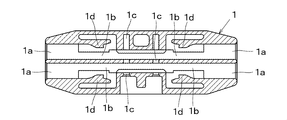
- connection member of the embodiment is a substantially rectangular holder 1 having a plurality of wire terminal insertion holes 1 a, receiving connection end holding holes 1 b, and through pin insertion holes 1 c, and receiving connection at the front end.
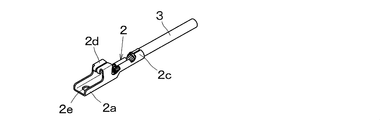
- a plurality of electric wire terminals 2 having a conductor crimping portion 2c having a cylindrical contact 2b at the end 2a and an electric wire 3 connected at the rear end, and a conductive connection portion 4b made of a rigid body having two through pins 4a. It is comprised by the insertion conduction
- the holder 1 is formed with wire terminal insertion openings 1 a that are arranged, for example, two in the vertical direction from the left and right sides.
- Each of the wire terminal insertion openings 1a communicates with a receiving connection end holding hole 1b for holding the receiving connection end 2a of the electric wire terminal 2 in the holder 1, and each receiving connection end holding hole 1b has flexibility.
- a locking lance 1d having a claw portion is formed.
- one through pin insertion hole 1c is formed penetrating in the vertical direction.
- thermoplastic synthetic resin is applied to the material of the holder 1.
- PBT polybutylene terephthalate
- PP polypropylene
- the vertical and horizontal sizes may be appropriately determined depending on the number and diameter of the electric wires 3 to be used, but the length is usually about 20 to 150 mm.
- the holder 1 is manufactured by injection molding a thermoplastic resin in a predetermined mold.
- the window is provided to mold the inside.
- it can be divided into a plurality of parts in a longitudinal section or a transverse section, and can be adhered or fitted together when used.
- the electric wire terminal 2 is formed by punching one conductive metal plate, and a front end tongue-like receiving connection end 2a is provided with a cylindrical contact 2b drawn into a short cylindrical shape in the vertical direction.
- a conductor crimping portion 2c is provided at the end, and the conductor of the electric wire 3 is crimped and connected by the conductor crimping portion 2c.
- a stabilizer 2d is formed at the rear part of the receiving connection end 2a so as to protrude as an upper portion of the receiving connection end holding hole 1b, and also serves as a locked portion that is locked to the locking lance 1d. ing.
- the wire terminal 2 may be formed by punching a copper plate or a copper alloy plate into a predetermined shape, using a Sn plating, or by punching and forming a Sn plated copper plate or copper alloy plate into a predetermined shape.
- the material is preferably brass in terms of strength and conductivity, and is further preferable in that the corrosion resistance is improved by Sn plating and the conductivity with the insertion conductive member 4 is easily obtained.
- the cylindrical contact 2b only needs to have a shape that conducts when it comes into contact with the insertion conducting member 4, so that the insertion conducting member 4 can be inserted from any of the upper and lower sides at the base and tip of the cylindrical contact 2b. It is desirable to provide a tapered guide. Further, even if it is not cylindrical, it may be a circular hole 2e or a polygonal hole as shown in FIG. 3, or a semicircular, U-shaped, V-shaped or concave cutout 2f as shown in FIG. Good.
- the insulated wire in which the outer periphery of the conductor is covered with an insulating layer is applied to the wire 3, and a wire having a known wire diameter can be applied.
- Conventional conductors are stranded copper or hard copper wires used in automotive harness circuits, or stranded wires or single wires of copper alloy wires such as Cu-Sn alloy wires that maintain tensile strength and have a small wire diameter. Is possible.
- conventionally known insulating materials are applied to the insulating layer, and among them, it is preferable to apply a non-halogen insulating material to the insulating layer as an environmental measure.
- connection between the conductor of the electric wire 3 and the electric wire terminal 2 is performed by known caulking, welding, soldering, crimping, etc., but in terms of the time required for connection and the connection strength obtained,
- the crimping connection by the conductor crimping part 2c is suitable.
- the insertion conductive member 4 is formed by connecting two conductive through pins 4a by a conductive connecting portion 4b made of a conductive rigid body.
- the through pin 4a and the conductive connecting portion 4b are integrally formed by one conductive plate. It is desirable to manufacture.
- jig holes 4c are provided on both sides of the conductive connecting portion 4b for hooking the operation jig.
- the through pin 4a is a rod-shaped member made of conductive metal for conducting the receiving and connecting ends 2a of the plurality of electric wire terminals 2, and the cross-sectional shape includes a circle, a triangle, a rectangle, a polygon, and the like.
- the contact shape of the electric wire terminal 2 is A cylindrical shape or a circular hole shape is preferable.
- the wire pin 2 while deforming the receiving / connecting end 2a side of the wire terminal 2 by making the through pin 4a harder than the receiving / connecting end 2a.
- the hardness of the through pin 4a and the receiving connection end 2a can be appropriately adjusted by processing, heat treatment, and selection of materials.
- the tip is a conical trapezoidal shape such as a conical shape, a pyramid shape, a truncated cone shape, a truncated pyramid shape or the like in order to be surely inserted into the cylindrical contact 2b.
- the through pin 4a is obtained by bending and folding a conductive metal plate, a substantially square cross section as shown in FIG. 5 can be obtained, and thereafter the tip can be formed into a cone shape by pressing or cutting. By producing by such a method, even the through pin 4a having a small cross-sectional area is less likely to be bent or broken.
- the contact point of the receiving connection end 2a is cylindrical or circular, the inner diameter is d1, the cross-sectional shape of the through pin 4a is substantially square, and the length of the diagonal line is x, d1 ⁇ x. preferable.
- the through pin 4a may have a circular cross section, and the contact of the receiving connection end 2a may be a hole having a square side of d1 in length. In this case, when the circular outer diameter of the through pin 4a is d2, it is preferable that d1 ⁇ d2.
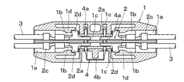
- FIG. 6 is a perspective view of the connecting member in an assembled state
- FIG. 7 is a sectional view thereof.
- the stabilizer 2d When the receiving connection end 2a of the electric wire terminal 2 reaches a predetermined position, the stabilizer 2d is pulled out of the locking lance 1d, so that the locking lance 1d is restored and the rear portion of the stabilizer 2d is locked by the claw portion. Thereby, the electric wire terminal 2 is latched in the holder 1, and coming out is prevented. At this time, the centers of the cylindrical contacts 2b of the receiving connection ends 2a on both sides coincide with the central axis of the through pin insertion hole 1c.
- the two through pins 4a of the insertion conducting member 4 are inserted into the through pin insertion holes 1c of the holder 1, respectively.
- This insertion requires a certain amount of force, but it can be easily done by hooking the jig into the jig hole 4c provided in the conductive connecting portion 4b, and gripping and pushing in the integrated insertion conducting member 4. Can be inserted.
- connection member By attaching an insulating cover on the outside or winding an insulating tape on the connection member assembled in this way, there is no risk of each electrical conductive member short-circuiting with an external conductive member. It becomes possible.
- two electric wire terminals 2 are laminated on each side, and a total of four electric wire terminals 2 are used.
- the present invention can be carried out even if one piece from both sides or the number of both sides is not the same.
Abstract
Description
実施例の接続部材は図1の分解斜視図に示すように、複数の電線端子挿入口1a、受接続端保持孔1b、スルーピン挿入孔1cを有する略長方形状のホルダ1と、前端の受接続端2aに筒状接点2bを設け、後端に電線3を接続した導体圧着部2cを有する複数の電線端子2と、2本のスルーピン4aを備え剛体から成る導電連結部4bを介してコ字型に連結した挿込導通部材4とにより構成されている。 The present invention will be described in detail based on the embodiments shown in the drawings.
As shown in the exploded perspective view of FIG. 1, the connection member of the embodiment is a substantially
1a 電線端子挿入口
1b 受接続端保持孔
1c スルーピン挿入孔
1d 係止ランス
2 電線端子
2a 受接続端
2b 筒状接点
2c 導体圧着部
2d スタビライザ
3 電線
4 挿込導通部材
4a スルーピン
4b 導通連結部
4c 治具孔 DESCRIPTION OF
Claims (6)
- 両端に設けた電線端子挿入口とそれぞれ連通する受接続端保持孔を内部に直列的に配すると共に、前記受接続端保持孔は2個のスルーピン挿入孔の1個とそれぞれ交叉するようにしたホルダと、一端に受接続端を有し他端に電線を接続し前記受接続端を両側の前記電線端子挿入口を経て前記受接続端保持孔にそれぞれ挿入する少なくとも2個の電線端子と、平行な2本のスルーピンを平行に配置すると共にこれらのスルーピン同士を剛体から成る導電連結部によりコ字型に連結した挿込導通部材とから成り、前記電線端子の受接続端を前記ホルダの両側の前記電線端子挿入口を経てそれぞれ前記受接続端保持孔に挿入し、前記挿込導通部材のスルーピンを前記ホルダのスルーピン挿入孔にそれぞれ挿入することにより、前記ホルダ内の前記電線端子の受接続端の接点と接触し、両側からそれぞれ挿入した前記電線端子同士を短絡することによって電気接続することを特徴とする接続部材。 The receiving connection end holding holes respectively communicating with the wire terminal insertion ports provided at both ends are arranged in series inside, and the receiving connection end holding holes intersect with one of the two through pin insertion holes, respectively. A holder, at least two wire terminals having a receiving connection end at one end, connecting an electric wire to the other end, and inserting the receiving connection end into the receiving connection end holding holes through the wire terminal insertion holes on both sides; It comprises an insertion conducting member in which two parallel through pins are arranged in parallel and these through pins are connected in a U-shape by a conductive connecting portion made of a rigid body, and the receiving end of the wire terminal is connected to both sides of the holder Are inserted into the receiving connection end holding holes respectively through the wire terminal insertion holes, and the through pins of the insertion conducting members are respectively inserted into the through pin insertion holes of the holder, thereby Connecting member, characterized in that the electrical connection by contact with the contacts of the receiving connecting end of the line terminal, to short-circuit the electric wire terminals are inserted respectively from both sides.
- 前記電線端子は前記スルーピンの挿入方向においても積層したことを特徴とする請求項1に記載の接続部材。 The connection member according to claim 1, wherein the electric wire terminals are laminated also in the insertion direction of the through pins.
- 前記受接続端の接点は、前記スルーピンを挿通する筒形としたことを特徴とする請求項1に記載の接続部材。 The connection member according to claim 1, wherein the contact point of the receiving connection end has a cylindrical shape through which the through pin is inserted.
- 前記スルーピンの横断面は略四角形としたことを特徴とする請求項3に記載の接続部材。 4. The connecting member according to claim 3, wherein the through pin has a substantially rectangular cross section.
- 前記受接続端保持孔内には前記電線端子を係止する係止ランスを設けたことを特徴とする請求項1に記載の接続部材。 The connection member according to claim 1, wherein a locking lance for locking the electric wire terminal is provided in the receiving connection end holding hole.
- 請求項1~5の何れか1つの請求項に記載の接続部材を使用したことを特徴とする自動車用ハーネス回路。 An automotive harness circuit using the connection member according to any one of claims 1 to 5.
Priority Applications (2)
| Application Number | Priority Date | Filing Date | Title |
|---|---|---|---|
| CN200980118855.1A CN102037621B (en) | 2008-05-23 | 2009-05-21 | Connecting member |
| KR1020107023523A KR20110013369A (en) | 2008-05-23 | 2009-05-21 | Connecting member |
Applications Claiming Priority (2)
| Application Number | Priority Date | Filing Date | Title |
|---|---|---|---|
| JP2008-135104 | 2008-05-23 | ||
| JP2008135104A JP5390792B2 (en) | 2008-05-23 | 2008-05-23 | Connecting member |
Publications (1)
| Publication Number | Publication Date |
|---|---|
| WO2009142273A1 true WO2009142273A1 (en) | 2009-11-26 |
Family
ID=41340200
Family Applications (1)
| Application Number | Title | Priority Date | Filing Date |
|---|---|---|---|
| PCT/JP2009/059376 WO2009142273A1 (en) | 2008-05-23 | 2009-05-21 | Connecting member |
Country Status (4)
| Country | Link |
|---|---|
| JP (1) | JP5390792B2 (en) |
| KR (1) | KR20110013369A (en) |
| CN (1) | CN102037621B (en) |
| WO (1) | WO2009142273A1 (en) |
Cited By (2)
| Publication number | Priority date | Publication date | Assignee | Title |
|---|---|---|---|---|
| WO2017045769A1 (en) * | 2015-09-17 | 2017-03-23 | Sew-Eurodrive Gmbh & Co. Kg | Arrangement for connecting the lines of an electric cable, and electric device having such an arrangement |
| CN109541971A (en) * | 2018-11-22 | 2019-03-29 | 许汉平 | A kind of control method of high stability socket |
Families Citing this family (2)
| Publication number | Priority date | Publication date | Assignee | Title |
|---|---|---|---|---|
| US9869403B2 (en) | 2011-05-09 | 2018-01-16 | Hamilton Sundstrand Corporation | Valve having pressure-relieving vent passage |
| CN104810647B (en) * | 2015-05-06 | 2017-06-16 | 宁波博禄德电子有限公司 | Connector PIN short circuits attachment structure, Male head connector and its processing method |
Citations (5)
| Publication number | Priority date | Publication date | Assignee | Title |
|---|---|---|---|---|
| JP2000323196A (en) * | 1999-05-12 | 2000-11-24 | Omron Corp | Connector for branching cabtire cable and connector holder thereof |
| JP2001023743A (en) * | 1999-06-28 | 2001-01-26 | Stocko Contact Gmbh & Co Kg | Plug connector of electric cable having short circuit bridge |
| JP2003223944A (en) * | 2002-01-30 | 2003-08-08 | Furukawa Electric Co Ltd:The | Electrical connection equipment |
| JP2004095246A (en) * | 2002-08-30 | 2004-03-25 | Furukawa Electric Co Ltd:The | Connector for flat cable |
| JP2007317434A (en) * | 2006-05-24 | 2007-12-06 | Mitsubishi Cable Ind Ltd | Connection member |
Family Cites Families (4)
| Publication number | Priority date | Publication date | Assignee | Title |
|---|---|---|---|---|
| JP3387233B2 (en) * | 1994-08-30 | 2003-03-17 | 住友電装株式会社 | Joint connector |
| JP2004311269A (en) * | 2003-04-09 | 2004-11-04 | Auto Network Gijutsu Kenkyusho:Kk | Joint connector |
| JP4519539B2 (en) * | 2003-07-17 | 2010-08-04 | 株式会社オートネットワーク技術研究所 | Joint connector for wire harness |
| ITMI20041463A1 (en) * | 2004-07-20 | 2004-10-20 | Vincenzo Corradi | DEVICE FOR THE ELECTRICAL CONNECTION OF DISCONTINUOUS CONDUCTORS |
-
2008
- 2008-05-23 JP JP2008135104A patent/JP5390792B2/en active Active
-
2009
- 2009-05-21 WO PCT/JP2009/059376 patent/WO2009142273A1/en active Application Filing
- 2009-05-21 KR KR1020107023523A patent/KR20110013369A/en not_active Application Discontinuation
- 2009-05-21 CN CN200980118855.1A patent/CN102037621B/en not_active Expired - Fee Related
Patent Citations (5)
| Publication number | Priority date | Publication date | Assignee | Title |
|---|---|---|---|---|
| JP2000323196A (en) * | 1999-05-12 | 2000-11-24 | Omron Corp | Connector for branching cabtire cable and connector holder thereof |
| JP2001023743A (en) * | 1999-06-28 | 2001-01-26 | Stocko Contact Gmbh & Co Kg | Plug connector of electric cable having short circuit bridge |
| JP2003223944A (en) * | 2002-01-30 | 2003-08-08 | Furukawa Electric Co Ltd:The | Electrical connection equipment |
| JP2004095246A (en) * | 2002-08-30 | 2004-03-25 | Furukawa Electric Co Ltd:The | Connector for flat cable |
| JP2007317434A (en) * | 2006-05-24 | 2007-12-06 | Mitsubishi Cable Ind Ltd | Connection member |
Cited By (2)
| Publication number | Priority date | Publication date | Assignee | Title |
|---|---|---|---|---|
| WO2017045769A1 (en) * | 2015-09-17 | 2017-03-23 | Sew-Eurodrive Gmbh & Co. Kg | Arrangement for connecting the lines of an electric cable, and electric device having such an arrangement |
| CN109541971A (en) * | 2018-11-22 | 2019-03-29 | 许汉平 | A kind of control method of high stability socket |
Also Published As
| Publication number | Publication date |
|---|---|
| CN102037621B (en) | 2014-03-19 |
| CN102037621A (en) | 2011-04-27 |
| JP5390792B2 (en) | 2014-01-15 |
| JP2009283330A (en) | 2009-12-03 |
| KR20110013369A (en) | 2011-02-09 |
Similar Documents
| Publication | Publication Date | Title |
|---|---|---|
| JP4898296B2 (en) | Connecting member | |
| EP2101376B1 (en) | Connection member and harness connector | |
| EP2083480B1 (en) | Connector terminal having electrical wire and connector receiving the same | |
| JP5244427B2 (en) | Electronic component mounting / insulator-integrated inner conductor terminals and coaxial connectors | |
| US7883361B2 (en) | Connection member and harness connection body using the connection member | |
| EP2117080A1 (en) | Harness connection member | |
| JP4833826B2 (en) | Connection member and harness connection body using the member | |
| WO2009142273A1 (en) | Connecting member | |
| JP4495066B2 (en) | Joint connector | |
| JP2014075245A (en) | Electric wire, and connection structure of the same | |
| JP4800066B2 (en) | Connecting member | |
| JP4885704B2 (en) | Harness connector | |
| JP4813973B2 (en) | Connecting member | |
| JP4695013B2 (en) | Waterproof joint connector | |
| JP4898295B2 (en) | Connecting member | |
| JP4885705B2 (en) | Harness connector | |
| JP4933246B2 (en) | Connection member and harness connection body using the connection member | |
| JP7431091B2 (en) | Connecting terminal | |
| JP4988481B2 (en) | Harness connecting member | |
| JP2024049620A (en) | TERMINAL-WIRED ASSEMBLY AND TERMINAL CONNECTION STRUCTURE | |
| KR20010083699A (en) | Manufacturing Method of Ribbon Cable |
Legal Events
| Date | Code | Title | Description |
|---|---|---|---|
| WWE | Wipo information: entry into national phase |
Ref document number: 200980118855.1 Country of ref document: CN |
|
| 121 | Ep: the epo has been informed by wipo that ep was designated in this application |
Ref document number: 09750635 Country of ref document: EP Kind code of ref document: A1 |
|
| ENP | Entry into the national phase |
Ref document number: 20107023523 Country of ref document: KR Kind code of ref document: A |
|
| NENP | Non-entry into the national phase |
Ref country code: DE |
|
| 122 | Ep: pct application non-entry in european phase |
Ref document number: 09750635 Country of ref document: EP Kind code of ref document: A1 |